RANIMELAHDAB InPartialFulfillment oftheRequirements …docs.neu.edu.tr/library/6367834284.pdf ·...
86
IMPRINTIN' OF NANOTEXTURED POROUS POLYMER USIN' POROUS SILICON SCAFFOLD A THESIS SUBMITTED TO THE 'RADUATE SCHOOL OF APPLIED SCIENCES OF NEAR EAST UNIVERSITY By RANIM EL AHDAB In Partial Fulfillment of the Requirements for the Degree of Master ofScience in Biomedical Engineering NICOSIA, 2015
Transcript of RANIMELAHDAB InPartialFulfillment oftheRequirements …docs.neu.edu.tr/library/6367834284.pdf ·...
IMPRINTING OF NANOTEXTURED POROUS POLYMER USING
POROUS SILICON SCAFFOLD
A THESIS SUBMITTED TO THEGRADUATE SCHOOL OF APPLIED SCIENCES
OFNEAR EAST UNIVERSITY
By
RANIM EL AHDAB
In Partial Fulfillment of the Requirements for the Degree ofMaster of Science
in
Biomedical Engineering
NICOSIA, 2015

Ranim El Ahdab: Imprinting of Nanotextured Porous PolymerUsing Porous Silicon Scaffold
We certify this thesis is satisfactory for the award of the degreeof Masters of Science in Biomedical Engineering
Examining Committee in Charge:
Assoc. Prof. Dr. Dudu Özkum,
ifk_ Faculty of Pharmacy, NEU
in Adalı, Biomedical EngineeringDepartment, NEU
Assoc. Prof. Dr. Fa'eq Radwan, Supervisor, BiomedicalEngineering Department,NEU

I hereby declare that all information in this document has been obtained and presented in
accordance with academic rules and ethical conduct. I also declare that, as required by these rules
and conduct, I have fully cited and referenced all material and results that are not original to this
work.
Name, last name: Ranim El Ahdab
Signature:~
Date: :2.9/o4/ ..2o)5 •

ACKNOWLEDGMENT
I primarily and chiefly, I would like to express my great appreciation and indebtedness to my
advisor Assistant Prof Dr. Mohamad Hajj-Hassan on behalf of his provision, up keeping,
support, words, assistance along with the freedom throughout the progress of my Master thesis
research. He was constantly helpful and over welcoming to share his acquaintance and rich
knowledge and experience regarding exploratory along to personal issues. I am utterly blessed
and grateful for his presence in my academic and private daily life. He guided to the word of
curiosity to science and to the road of research. All along he offered me "a constant faith in my
capabilities" and a "strong beliefs in achieving my dreams". He helped me to develop my
confident not only to grow as scientist but also as a professor and an independent researcher.
Moreover, I would like to declare the enormous support from NEU Grand library administration
members for the appropriate environment they provided for conducting my research and writing
my thesis.
Additionally, I am very grateful for my family, in particular my father who sacrificed his life to
offer me a life. He was always there for me to support me and guide me in any decision I took
il

ll 1
ABSTRACT
Porous polymers are invading ubiquitously the engineering markets as well as other fields.
They are constantly earning attention and scientist's curiosity owing this to their inimitable
chemical, physiochemical, optical, mechanical and surface area properties and morphology.
Polymers whether natural, polymerized, modified or synthesized; they are manufactured based
on the background of their particular chemical arrangement. In this research, an all-purpose
manufacturing progression desired to work out with all liquid or powder polymers cross linked to
a flexible phase to imprint their surface with any desired porosity.
The work is founded into two micro-casting phases. The project can be described as stamping.
The basic stamp is a microchip made of porous silicon (PS) template prepared based on xenon
difluoride (XeF2) dry etching technique. The former "stage l" forms a layer of polymer
complement to the silicone sample where this latter layer is complemented to get a final version
cloning the pores of the silicon porous sample. The last version is just "dressmaking fashioned
polymer" that is identical to the texture of the silicon pores. A laidback, bendable scheme that
permits to manufacture porous polymer textured with the intended pores using a sought after
pore size and configuration porous silicon prototypes.
This work offers a future hope and ambitions that are extended to the solicitation of stamped Poly
ethyl hydrosiloxane (PMHS), Poly-Dimethylsiloxane (PDMS) using porous silicon and Poly
methyl methacrylate (PMMA) scaffolds or any silicon-polymer combination to reach the final"
porous polymer suitable to the desired biomedical application.
Keywords: Polymer, porous silicon, PMMA, PDMS, PMHS, micro-molding

ÖZET
Gözenekli polimer mühendislik piyasasini ve diğer alanları tumuyle yanı sıra işgal vardır istila
ediyor.
Onlar sürekli dikkat ve bilim adamının merak bu onların eşsiz kimyasal, physiochemical, optik,
mekanik ve yüzey alanı özelliklerini ve Morfoloji nedeniyle kazanç vardır. Polimerler olsun
doğal, polimerli, değiştirilmiş veya sentez; Onlar kendi belirli kimyasal düzenleme arka plan
üzerinde göre üretilmektedir. Bu araştırmada, tüm sıvı ile çalışacak bir çok amaçlı üretim
ilerlemesi istenen veya onların yüzey ile istediğiniz herhangi bir gözeneklilik Künye için esnek
bir aşaması için toz polimerler çapraz bağlanmış.
Çalışma iki mikro-döküm aşamalar halinde kuruldu. Proje damgalama olarak tanımlanabilir.
Hazırlanan gözenekli Silisyum (PS) şablon I yapılan bir mikroçip xenon difluoride üzerinde
(XeF2) tekniği aşındırma kuru dayalı temel damgasıdır. Eski "1. aşama" formları polimer bir
katman nerede bu ikinci katman silikon gözenekli örnek gözeneklerin klonlama a sonda gelen
yorum almak için tamamlanmaktadır silikon örnek tamamlıyor. Sadece "terzilik moda polimer"
en son sürüm olan silikon gözenekleri doku için aynı. Bir aranan sonra gözenek büyüklüğü ve
yapılandırmasını gözenekli Silisyum prototip kullanarak hedeflenen gözenekli bir laidback,
gözenekli polimer üretim izni bükülebilir düzeni dokulu.
Bu eser gelecek umut ve damgalı Poly-etil hydrosiloxane (PMHS), Poli-Dimethylsiloxane
"(PDMS) son gözenekli polimer istediöiniz Biyomedikal uygulamaya uygun ulaşmak için
gözenekli Silisyum ve Poly-metil metakrilat (PMMA) İskele veya silikon polimer bunlarınbir
kullanımı talep için genişletilmiş emelleri sunmaktadır.
Anahtar Kelimeler: Polimer, Gözenekli polimer, PMMA, PDMS,
IV

TABLE OF CONTENTS
ACKNOWLEDGMENT..................................................................................................... 11
ABSTRACT.......................................................................................................................... 111
ÖZET.................................................................................................................................... IV
TABLE OF CONTENTS....................................................................................... V
LIST OF TABLES.................................................................................... Vlll
LIST OF FIGURES............................................................................................................. IX
LIST OF ABBREVIATION........................................................................ XU
CHAPTER 1: INTRODUCTION
1. 1 Introduction .
1 .2 Literature Review of Polymers........................................................................................ 4
1.3 Contributions of the Proposed Work............................................................................... 5
1.4 Aim of Thesis................................................................................................................... 5
1.5 Thesis Overview.............................................................................................................................6
CHAPTER 2: POROUS POLYMERS AND POROUS SILICON CHIP:TYPICAL APPLIED METHODS AND APPLICATIONS
2.1 Polymers Vital Applications........................................................................................... 8
2.2 Modification of Polymers Surfaces Properties for Improving their Functionality......... 1 O
2.3 Fabrication of Porous Polymer....................................................................................... 12
2.3 .1 Applied Methods for Porous Polymer Development........................................ 13
2.4 Porous Silicon: Definition and Background'..................................................................... 15
2.4. 1 Causes for the Limitation of Porous Silicon Biological Applications............... 16
2.5 Porous Silicon Manufacturing Techniques :..... 16
2.5. 1 Porous Silicon Manufacturing Using Wet Etching............................................ 17
2.5.1. 1 Advantages and Draw Back of Porous Silicon Manufacturing UsingWet Etching.............................................................................. 19
2.5.2 Porous Silicon Manufacturing Using Dry Etching............................................ 19
V

2.5.2. 1 Dry Etch Fabrication of Porous Silicon Using Xenon difluoride 20
(XeF2) .
2.5.2.2 Advantages and Disadvantages of Dry Etching Method.................... 21
2.6 Proposed Generic Recipe.................................................................................................. 21
CHAPTER 3: GENERIC FABRICATION PROCESS: POROUS POLYMERIMPRINTING STAGES
3.1 Curing Polyıners Process................................................................................................ 23
3 .2 Proposed Generic Recipe Methodology . . . . . . . . . . . . . . . . . . . . . . . . . . . . . . . . . . . . . . . . . . . . . . . . . . . . . . . . .. . . . . . . . . . . . . . . . 23
3.3 Porous Silicon Scaffold................................................................................................... 25
3 .3 .1 Porous Silicon Scaffold Manufacturing Technique........................................... 26
3 .4 Porous Polyıner Development . . . .. . . .. . . . . . . . . . . . . . . . . . . . . . . . . . . . . . . . . . . . .. . . . . . . .. . . . . . . . . . . . . . . . . . . . . . . . . . . . . . . . . . . 28
3 .4. 1 Porous PMMA Polyıner Development Phase.................................................... 29
3.4.1.1 PMMA Chemical Characteristics............................................ 29
3.4.1.2 PMMA Cross-Linking Reagent: Dichloromethane.... 30
3.4.1.3 PMMA Curing Recipe Parameters........................................... 30
3 .4. 1 .4 Cured PMMA Experiments Efficiency Testing............................. 31
3 .4. 1.5 Porous PMMA Development . . . .. . . . . . . . . . . . . . . . . . . . . . . . . . . . . . . . . . . . . . . . . . . . . 32
3 .4. 1.6 Characterization of Porous Cured Polyıner................................. 34
3.4.2 Porous PDMS Polyıner Development Phase..................................................... 34
3.4.2.1 PDMS Chemical Characteristics............................................. 34
3.4.2.1 PDMS Cross-Linking Reagent: Glutaraldehyde.. ... . . . .. . . . . . . . . . . . . .. .... 35
3.4.2.3 PDMS Curing Recipe Parameters............................................ 36
3.4.2.4 Cured PMMA Experiments Efficiency Testing............................. 37
3.4.2.5 Porous PMMA Development................................................. 37
3.4.2.6 Characterization of Porous Cured Polyıner. '..... .. 37
CHAPTER 4: POROUS POLYMER MIMICKING SILICON SCAFFOLDDEVELOPMENTAL STAGES
4.1 PMMA Polyıner Curing Process.................................................................................... 38
4. 1. 1 Characterization of Porous Cured Polyıner..................................... 38
4. 1.2 PMMA Curing Experiment Efficiency Evaluation............................................ 41
VI

Vil
4. 1.2.1 PMMA Transparency Test Analysis and Evaluation.......................... 41
4. 1.2.2 PMMA Mechanical Performance PMMA Cured Polymers............... 45
4.1.2.3 PMMA Curing Polymer Experiment Selected................................... 47
4.1.3 Development of Porous PMMA by Application of Selected Experiment......... 47
4.2 PDMS Polymer Curing Process........................................................................................ 48
4.2.1 PDMS Curing Experiments and Resulting Polymers........................................ 48
4.2.2 PDMS Curing Experiment Efficiency Evaluation............................................. 50
4.2.2. 1 PDMS Transparency Test Analysis and Evaluation........................... 50
4.2.2.2 Mechanical Performance of PDMS Cured Polymer..................... 51
4.2.3 Development of Porous PDMS by Application of Selected Experiment.......... 51
CHAPTER 5: RESULTS AND DISCUSSION
5.1 Development of Porous PMMA 53
5. 1.1 PMMA Morphology and Microstructure Properties Analysis 55
5.2 Development of Porous PDMS......................................................................................... 58
5 .2. 1 PDMS Morphology and Microstructure Properties Analysis............................ 59
5.3 Novelty of the Generic Recipe: Results of Comparison with Typical Applied Porous
Polymer Fabrication........................................................................................................ 61
CHAPTER 6: CONCLUSION
6.1 Conclusion . . . .. . . .. . . . . . . . . . . . . . . . . .. . . . . .. . . . . . . . . . . . . . . . . . . . . . . . . . . . . . . . . . . . . . . . . . . . . . . .. . . . . . . . . . . . . . . . . . . . . . . . . . . . . . . . . . . . . ... 63
6.2 Recommendation and Future Work.................................................................................. 64
REFERENCES 67

LIST OF TABLES
Table 4.1: Table showing the conditions (temperature and r (mPMMA: VDichloromethane))
used for each experiment........................................................... 38
Table 4.2: Table depicting the calculated average % efficiency of each recipe applied fora developed polymer based on the light reflection basis......................... 44
Table 4.3: Table showing the% Average deformation ensued for several trials for eachdeveloped polymer........................................................................ 46
Table 5.1: Table showing the compared factors of the generic recipe proposed andtypical methods.............................................................................. 62
V111
---

30
List of Figures
Figure 1.1: Picture depicting the clinical applications and types of polymers used inmedicine...................................................................................................... 2
Figure 2.1: Cross sectional SEM image of porous silicon material undergoing XeF2etching................................................................................... 20
Figure 2.2: Schematic representation of the proposed generic fabrication process ofporous polymer. . . . . . . . . . . . . . . . . . . . . . . . . . . . . . . . . . . . . . . . . . . . . . . . . . . . . . . . . . . . . . . . . . . . . . . . . . . . .. . 22
Figure 3.1: Figure displaying the basic of the project the silicon chip.............................. 25
Figure 3.2: Illustration displaying the pores on the silicon chip and its according step inthe generic recipe applied........................................................................... 25
Figure 3.3: An illustration showing the porous part on two silicon samples....................... 26
Figure 3.4: Picture depicting the dry etching of bulk silicon and creation of pores27
Figure 3.5: Porous silicon template on the top and in the bottom Scanning electronmicrograph of a porous silicon template textured with XeF2 . 28
Figure 3.6: Picture denoting the polymerization of methylmethacrylate to Poly(methylmethacrylate) . 29
Figure 3.7: Figure displaying the chemical structural formula of dichloromethane
Figure 3.8: Network analyzer (Agilent HP 80350A 8756A-10 MHz to 40 GHz)............. 32
Figure 3.9: An illustration depicting the addition of PMMA on the top of silicontemplate before curing process ·ı.··........................................ 33
Figure 3.10: an illustration representing the critical step in the proposed generic recipe;PMMA complementing the pores of silicon template throughout curingprocess................................................................................... 33
Figure 3.11: Figure displaying the chemical structural formula of Poly-(dimethylsiloxane ),bis-(3-aminopropyl)terminate... . . . . . . . . . . . . . . . . . . . . . . . . . . . . 35
Figure 3.12: Figure displaying the chemical structural formula of Glutaraldehyde......... .. 36
Figure 3.13: An illustration showing the last step resulting with the development of finalporous PDMS identical to silicon scaffold........................................ 37
IX

Figure 4.10: The transmission percentage of the cured polymer by experiment 5 upon anemitted UV wave length............................................................ 44
Figure 4.1: Two similar samples of PMMA cured with experiment 1 parameters.... 39
Figure 4.2: Two PMMA samples cured at room temperature with experiment 2parameters.............................................................................. 39
Figure 4.3: Pictures of two samples obtained after being cured with experiment............ 40
Figure 4.4: Pictures of cross-linked PMMA in the oven at 126°C for 2 minutes......... 40
Figure 4.5: Three different samples resulting from experiment 5 prepared at 126°C for 2minutes................................................................................... 41
Figure 4.6: The transmission percentage of the cured polymer by experiment 1 by UVvisible spectrophotometer............................................................ 42
Figure 4.7: The transmission percentage of the cured polymer by experiment 2 upon anemitted UV wave length............................................................. 42
Figure 4.8: The transmission percentage of the cured polymer by experiment 3 upon anemitted UV wave length.............................................................. 43
Figure 4.9: The transmission percentage of the cured polymer by experiment 4 upon anemitted UV wave length.............................................................. 43
Figure 4.11: The transmıssıon percentage of the cured polymer via the 5 differentexperiments performed upon an emitted UV wave length................... 44
Figure 4.12: Chart depicting the amelioration of efficiency throughout experiment'sratio experimental realm............................................................ 45
Figure 4.13: Picture showing the measurements of the diameter of the polymer afterdeformation realized. . . . . . . . . . . . . . . . . . . . . . . . . . . . . . . . . . . . . . . . . . . . . . . . . . . . . . . . . . . . . . . . . . . 46
••Figure 4.14: A graph depicting the % average deformation taking place in the polymer
after the deformation.................................................................. 46
Figure 4.15: Assessment for the most efficient curing experiment to be applied tocomplement pores on the silicon chip............................................. 47
Figure 4.16: Figures depicting silicon chip covered with 25 mg of PMMA afterbeing weighted on an electronic scale on the left side while on the rightside 75 ml immersed PMMA and Dichloromethane just before curingprocess................................................................................. 48
X

Figure 4.17: Pictures depicting experiment 1 that failed to give the desired results forcuring PDMS........................................................................... 49
Figure 4.18: Pictures depicting the cured polymer with the experiment of ratio(VPDMS: VGluteraldehyde): (1 :9) .. · · · · · · · · · .. · .. · · .. · .. · · · .. · 49
Figure 4.19: Pictures depicting the cured polymer with the experiment of (vrDMS:VGluteraldehyde) ratio equal (1 :10).............................................................. 49
Figure 4.20: PDMS cured at room temperature for (VPDMS:VGluteraldehyde):(1: 11)ratio application... . . . . . . . . . . . . . . . . . . . . . . . . . . . . . . .. .. .. .. .. .. .. .. .. .. .. .. . .. .. .. .. .. .. .. .. .. .. .. .. .. 50
Figure 4.21: The transmission percentage of the cured PDMS upon an emitted UV wavelength 680 nm................................................................................................... 51
Figure 4.22: An illustration clarifying the step of generating porous PDMS step on thegeneric experiment diagram.......................................................... 52
Figure 5.1: Illustration clarifying the resulting porous PMMA on the genericexperiment diagram.................................................................... 54
Figure 5.2: An illustration depicting the porous polymer PMMA............................. .. 54
Figure 5.3: Picture showing the true scale of porous PMMA compared to a pen............. 55
Figure 5.4: Picture taken by the SEM for porous PMMA......... .. . . . . . . . . . . . . . . . . ... . . . . . . . . .. 56
Figure 5.5: Picture taken by the SEM for porous PMMA from different angles.............. 56
Figure 5.6: SEM Image of porous PMMA at 50µm............................................... 57
Figure 5.7: SEM Image of porous PMMA at 50µm............................................... 57
Figure 5.8: On the left the mold PMMA, on the right the complementing porous curedPDMS similar to silicon................................................................ 58
Figure 5.9: PDMS sample size compared to the top of the pen :·..... 59
Figure 5.10: PDMS SEM images at 5 Kv............................................................ 60
Figure 5.11: PDMS SEM images at 3 Kv........... .... . .. .. .. .. . .. .. . .. . .. . .. . . .. .. .. .. .. .. . . .. .... 60
Figure 6.1: Anatomical representation of the uterus...... .. .. .. .. .. .. .. .. .. .. .. . .. .. .. .. .. .. .. .. .. . 65
XI

List of Abbreviations
PMMA: Poly (methymethacrylate)
PDMS: Poly (dimethylsiloxane), bis (3-aminopropyl) terminate
PMHS: Poly (methylhydrosiloxane)
PDS: Photo-detection coordination
SE: Spectroscopic ellipsometrical
SEM: Scanning electron microscope
XeF2: Xenon difluoride
Si: Silicon
SiF4:Tetrafluorosilane
Xe: Xenon
~02: Nitrogen dioxide
H20: Water
02: Oxygen
HN03: Nitric acid
HN02: Nitrous acid.
NO: Nitric oxide.
Si02: Silicon dioxide.
HF: Hydrogen fluoride.
SOI: silicon-on-insulator.
PS: Porous silicon.
H202: Hydrogen peroxide (H202).
He-Ne: Helium-Neon.
WE: Working electrode.
(MWE): Metal working electrode.
(SCE): Standard calomel electrode.
(PtE): Point counter electrode.
(Tc): Critical temperature.
Xll
1
CHAPTER 1INTRODUCTION
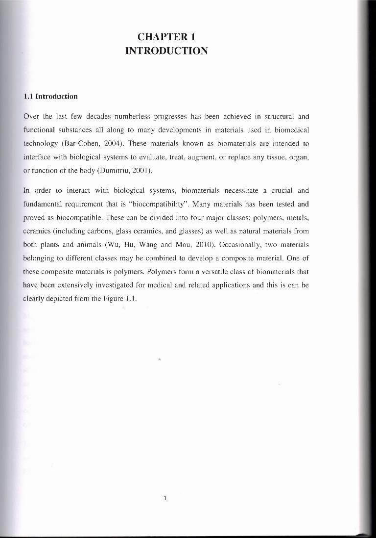
1.1 Introduction
Over the last few decades numberless progresses has been achieved in structural and
functional substances all along to many developments in materials used in biomedical
technology (Bar-Cohen, 2004). These materials known as biomaterials are intended to
interface with biological systems to evaluate, treat, augment, or replace any tissue, organ,
or function of the body (Dumitriu, 2001).
In order to interact with biological systems, biomaterials necessitate a crucial and
fundamental requirement that is "biocompatibility". Many materials has been tested and
proved as biocompatible. These can be divided into four major classes: polymers, metals,
ceramics (including carbons, glass ceramics, and glasses) as well as natural materials from
both plants and animals (Wu, Hu, Wang and Mou, 2010). Occasionally, two materials
belonging to different classes may be combined to develop a composite material. One of
these composite materials is polymers. Polymers form a versatile class of biomaterials that
have been extensively investigated for medical and related applications and this is can be
clearly depicted from the Figure 1. 1.
••

Finger ıoınıs
Eaı & eaı partsFacialp.rostııesis ~ Dentures
Esophagus , Tracheal tubesLung, kiaıey & Hea~ & heart
ı,ver parts compoııentsHeart pacemaker
Gastrointestinalsegments
Biodegradablesutures
Bones 4 joints
Ear & eır partA: acrylic, polyethylene. şiliçone, polY<ııinyt chlorldıı) (PVC)Qentına: ııcryNc, ultrahigh molecular weight polyethylene (UHMWPE), epoxyF..,Jal PfD1lhe9lı: acrylic, PVC, polyurethane (PUA)T..ıı.t tutıea: ac:ryic. s!iconı, nylonHMıt & heert componıntı: polyester, sllicoııe, PVCHeett ıı-cımalıet: polyethylene, ac:eıaıLIHl9, lıklney l liver parts: polyester, polyaklehyde, PVCEıoplııguı ııgmenıs: polyethylene, polypropylene (PP). PVCBlood --.ls: PVC, polyest9fBloclıgnıdablt ıuıu'": PUAGestrcilntıııllnıl ıegınentı: silicones. PVC. nylonFltıger joint,: şilİQJOe, UHMWPEBoneı l jolntı: acrylic, nytoo, s~icone. PUA, PP. UHMWPEKMe Jointı: polyethylene
Figure 1.1: Picture depicting the clinical applications and types of polymers used inmedicine (Shtilman, 2003)
The main difference between polymers and metals or ceramics is that these former
materials are made up of repeated units called "mers" that are characteristically grouped
together under the structure of chains or macromolecules rather than lattice structures
(Ravichandran, 2010).
Materials made of polymers set up their final structure based on covalent bonds and
secondary interactions (Bar-Cohen, 2004). Their fundamental structure is composed of a
backbone along to side or pendant groups (Mathew and Alocilja, 2005). The backbone is
made up of atoms connected by covalent bçnd extending from one side to another closing
stage part. The backbone is often not only carbon but rather may contain other atoms such
as N, O, or Si. The ramified parts are the hydrogen atoms in organic and inorganic groups
connected to the backbone. Covalent bonds are utilized along the backbone of the chain but
only weak secondary forces such as hydrogen bonds or van der Waals forces are used for
cohesion between chains (Mavromatidis, Mankibi, Michel, and Santamouris, 2012).
These polymeric biomaterials account as a crucial for several biomedical applications that
assist to improve the human life or compensate the malfunction in human organ or
function. Some of these applications are orthopedic such as bone Cements, joint
2

3
Prostheses; cardiovascular applications such as heart valve, vascular graft, stents,
pacemakers and blood oxygenators; Ophthalmic Applications like contact Lenses, suture
Materials and tissue Engineering.
Porous polymers are polymers having an amorphous surface with various pore size and
shape. These porous materials are invading the world and grabbing wide interest due to
their large quiet field of applications. They are capturing augmented interest in quite few
field and applications due to their large surface area and unique physiochemical properties
(Murugan and Ramakrishna, 2007). They are characterized by special physiochemical
properties and can account for wide range of application flourishing from the human body
to controlled drug delivery along with electrically activated tissues such as brain, heart and
muscles given that it can be coupled with animals or computer/machine's interface opening
the door of developmental innovation in nanotechnology (Murugan and Ramakrishna,
2007).
Their exceptional properties expand to cover the following characteristics: lightweight,
fracture tolerant, bendable, compromises the possibility of being contemplated to almost
any feasible form to fit the intended application. All along some features may be settled,
controlled and customized as the desired features to accomplish and perform any task
beyond the human expectations (Bar-Cohen, 2004). Nowadays, they are invading a great
range of applications as biomaterials and catching the spot of huge adaptability and multi
purpose usage for a mass of biomedical solicitations (Bhatti, Chaudhary, Pandya, and
Kashyap, 2008).
These materials are being embraced in almost each discipline in medicine scanning
extracorporeal device to implants integrated into the human body where each application••
demands special criteria different manufacturing processes to provide special chemical and
physiochemical are in need (Dumitriu, 2001). Some of which may stay as long as it can
retain while others must be degradable as fast by means of potential to make available
space for tissue to replace it. By mean of both intentions the results from the usage of these
polymers concluded in more preferable results than the applications of biological objects
(Shtilman, 2003). From here the innate needs initiated to shift from the realm of
transplantation and application to the empire of fabrication to decrease the complications
for any application.

Porous polymers are conventionally manufactured using specific processes related to the
hernical structure of each polymer. Each liquid polymer needs a specific fabrication
process that includes the variation in pressure, temperature, and the cross-linking reagent
used to solidify the polymer. Accordingly, there is a range of methods that can be utilized
to prepare porous polymers. These methods include gas foaming, phase separation, small
liquid drops templating, colloid crystal templating, templating via self-assembly, molecular
imprinting, and bio-templating using natural biological templates. The dimension and
characteristics of the porous phase required differs according to the application of the
porous structural polymer that is to be produced and the manufacturing technique
employed.
The methods applied for pores formation necessitate a time all along to a very complicated
processes. The new approach related to the formation of porous polymers is to use a
generic recipe that forms a porous surface in regards to the type of polymer used. A
template of porous silicon will be used to form a scaffold of the polymer upon the usage of
different cross-linking reagents to solidify the liquid polymer.
1.2 Literature Review of Polymers
Introduction of degradable polymers in biomedical application was established in the 1960
when the idea of employing them as a resorbable matrices (Folkman and Long, 1966). The
start was with a drug delivery_system diffusing small molecules from one side to another
side of a silicon rubber tubing wall.
Then polymers were started to be used in temporary surgical implant and repair for1'
damaged tissue (Kulkarni, Pani, Neuman, and Leonard, 1966; Schmitt and Polistina, 1969).
After the success that has encountered with these polymers once interfered with human
body; biodegradable polymers and aliphatic polyesters were proved to be useful various
applications in medical field such as prosthetics, vascular graft, artificial skin implant,
screws and stents as well as plates for implant and short-term inner fixation of the bone,
pins, resorbable sutures for surgeries and so on.
4

Exploration on polymers and their wide applications has been dramatically increased over
last few decades due to the successful results resulting from any application using
polymers. Researchers were able to prove that some of these polymers are biocompatible,
may be sterilized, and stable for storage. Some of these polymers are Poly (methy
methacrylate) (PMMA), PDMS or Poly (dimethylsiloxane), bis (3-aminopropyl) terminate
and PMHS or simply Poly (methylhydrosiloxane).
With all the critical improvement that accompanied any application using polymer; these
polymers turn out from being barely a point of interest to researcher to become a crucial
material employed in biomedical applications.
1.3 Contributions of the Proposed Work
This thesis is a contribution to the nano-technology and MEMS market. This thesis is a
part of the continuing research of nanotechnology innovations that are day by day invading
our daily life to exist in numerous materials and applications all along to invade human
body to help for recovery or compensation of any malfunction. Nevertheless, this research
offers a new approach that may be applied to develop porous polymer in a chemistry lab
without necessitation of any high level technology or equipments. The procedure is a
simple straight forward procedure comprised of two micro-molding steps and a template
scaffold that is a porous silicon chip.
1.4 Aim of Thesis
Porous polymers are of huge interest in ı-human life since they account for billions of
revenue for the international market and they help to improve or recover the human quality
of life. Therefore, this project aims to develop a generic recipe that may be applied to
develop porous polymers in regards to the type of the polymer used. The intentions are to
use a porous template that is the scaffold a porous silicon chip previously manufactured
using XeF2 etching method. The polymers that are intended to be employed will be linked
using a corresponding cross-linker at the consequent temperature.
5

All along the polymers must be biocompatible since this is the major necessary factor that
must be present when working within the human body. Any debris or residual resulting
from the materials used throughout the fabrication process may affect the biocompatibility
properties of the polymer surface membrane. The generic recipe intends to use only liquid
polymers in the formation of the porous polymers, eliminating the probability of forming
any residuals which could affect the compatibility of the polymer surface membrane within
the human body.
Another aim is to develop porous polymer having good optical and mechanical
characteristics that's why these two factors were tested and accounted. Also, the other
target was to neglect the pressure factor while developing the porous polymer where no
need for complicated calculations in order to achieve a pressure to volume ratio within the
surface of the structure.
The overall aim was to develop a porous polymer having important optical, biocompatible
and mechanical properties using a generic recipe. This recipe is applicable to any liquid
polymer regardless of the pressure and just by acquainting the corresponding cross-linker
and temperature of the cross-linking procedure while using a template that is a porous
silicon chip.
1.5 Thesis Overview
The developed thesis is divided into 6 chapters that are structured as following:
Chapter 1: It introduces and defines polymers and shows its field of applications. It
discusses the aims settled all along to the contributions, and motivations. Additionally, it
highlights and shows the structure of the thesis.
Chapter 2: It provides an introduction about the polymers and porous polymers
applications and manufacturing processes. All along, it discusses an introduction about
porous silicon and porous silicon manufacturing technique. This chapter describes and
explains briefly the proposed generic recipe.
Chapter 3: It shows a thorough clarification about the proposed generic recipe beside the
materials and chemicals used. This chapter presents a clear explanation about the polymers
6

chieving the most optically and mechanically efficient curing formula to un
surface modification. Also, it explains the tests used to assess the efficiency of the recipe
pplied.
employed that are PMMA and PDMS all along to their correspondi
Additionally this chapter explains briefly the experimental procedures applie~~~ aim of("\"'.J,'t(*u~ -LEf~
Chapter 4: It discusses the different obtained sample polymer resulting from the different
xperiments for both PMMA and PDMS. It shows the elected experiment parameters based
on the Ol)Ü.cal and mechanical tests eiiıcıeccies; those that will be emplo-yeci when \)Outing
them on top of the corresponding scaffold. It also shows the optical and mechanical
efficiency of the samples experiments through tables and charts.
Chapter 5: It shows morphology, microstructure and Reflection properties analysis of the
porous polymer samples developed using SEM. All along it presents the pictures of the
obtained porous polymers. Moreover this chapter highlights the comparison phases that
show the novelty of the proposed generic recipe
Chapter 6: It shows the final conclusion and recommendations for further work in this
research.
7

CHAPTER2POROUS POLYMERS AND POROUS SILICON CHIP:TYPICAL APPLIED METHODS AND APPLICATIONS
This chapter provides a review background about the critical applications of polymers in
general and porous polymers in particular. The techniques used to make porous polymers
from bulk polymers will be explained. Discussion about silicon material and porous silicon
manufacturing techniques will be explained in general and the employed scaffold
manufacturing technique in detailed. All along a brief explanation of the proposed generic
recipe will be presented.
2.1 Polymers Vital Applications
Polymers play a vital role in human life since they may be employed in several
applications in biomedical field as well as any other field. These materials help to improve
the quality of human life since they made up a significant number of machine and medical
instruments. All along; they may replace or compensate a failure or malfunction of any
function in the human body.
The chief characteristic that sets polymers apart from metals and ceramics is that polymers
are made up of repeated units called "mers". These subunits are typically grouped together
in the form of chains or macromolecules rather than lattice structure which is the case of
ceramics. Polymeric materials employ covalent bonds all along to secondary interactions to
establish their basic structures.
They have been proven to be an appropriate environment for molecules proliferation and
contact. All along they provide an improvement of the steadiness, sensitivity and speed of
diverse biomedical devices and equipment (Jian et al., 2012). They have unique properties
of their surface area, special physiochemical properties (Wu, Hu, Wang, and Mou, 2010)
inexpensive and ease of manufacturing and multipurpose usage. Some of these polymers
are conducting materials with electronic and ionic conductivity. They can open wide range
of promising applications that help improving the human quality of life. These applications
8

Biopolymers have resulted with more satisfying results in any intended application and
function rather than any biological objects (Gad-el-Hak, 2005). Also these materials have
lessened the complications encountered with any contact in human body that use to be
depicted with old biological systems. From here the innate needs initiated to shift from the
realm of transplantation and application t~ the empire of fabrication to decrease the
complications for any application.
range from appliances implanted in the human body to controlled drug delivery. Polymers
may interfere and work in parallel with electrically activated tissues in the human body
such as brain, heart and muscles. They also can be coupled with animals or
computer/machine interface opening the door of developmental innovation ın
nanotechnology and back propagation neural network applications (Ravichandran, 2010).
Their exceptional and very important properties are countless. They have lightweight,
fracture tolerant, bendable, compromises the possibility of being mulled over to almost any
feasible form to fit the intended application along with customized features to acquaint
results that are beyond of desires (Bar-Cohen, 2004). Nowadays, polymers are invading a
great range of applications as biomaterials and are catching the spot of enormous flexibility
and multi-purpose usage for numerous targets in biomedical field (Bhatti et al., 2008).
These biomaterials are being employed in almost each discipline in medicine. They are
parts of extracorporeal device; implants integrated into the human body as well as other
many other applications. Each of these applications demands special criteria and different
manufacturing processes to provide polymers with special chemical and physiochemical
properties corresponding to the function they are intended to perform (Dumitriu, 2001).
Some of them may stay as long as it can retain in the human body. Others must be
degradable after a certain period in order to allow the cells to regenerate to its original
shape.
There are two types of polymers human made polymers or synthetic polymers and natural
or biopolymers that exist naturally in the environment. Each of these consists comprise a
broad range properties that plays an important and ubiquitous role in everyday life.
Synthetic and natural polymers were employed independently or combined to fit the need
of several biomedical applications.
9

10
Based on the advantages and improvement in the quality of functions and successful results
of any application with polymers over other materials; many researchers invested them in
biomedical field. These polymeric biomaterials have extensively revolutionized
orthopedics field. They have proved to be serviceable in two main applications in this area.
In the first application, polymers are employed for the purpose of fixation such as PMMA;
they act as a structural interface between the implant component and the bone tissue. In the
other application, polymers are used for one of the articulating surface components in a
joint prosthesis where Polyethylenes are widely used (Gad-el-Hak, 2005). They have also
played a crucial role in cardiovascular applications including mechanical heart valves,
vascular grafts, stents, pacemakers, and blood oxygenators. Earlier in old mechanical
valves design silicone rubber ball contained within a cage made up of Lucite also known as
poly-methyl methacrylate Where new ones employ only polymers. Moreover, these
polymers have improved the function of ophthalmic applications including in contact and
intraocular lenses, as well as intra-corneal implants (Kumari, Bugaut, Huppert, and
Balasubramanian, 2007).
Polymers both synthetic and natural have been an innovation in biomedical field that
helped to assist the human quality of life all along to compensate any failure of
malfunction. Polymers are offered the resemblance of many parts in the human body or
application that is intended to deal with the human body. There is countless of research
taking place on both tried and the new showing potential both natural and synthetic
polymers mutually with their relevance as implantable materials, controlled-release
carriers, scaffolds for tissue engineering or any other biomedical applications based on
polymer-composite materials.
2.2 Modification of Polymers Surfaces Properties for Improving their Functionality
Polymer surface is the outside layer of the polymeric material. The bulk polymer defines
its characteristics; material stability, its good performance and proper function over a long
time. The surface of the material will define the face of interaction with the surrounding, its
acceptance or rejection in cell society from the early stage of contact. Since it is very hard
to achieve these both characters at the same time good performance versus reliable
interaction phase; a new approach was admitted by researcher. The new procedure was

Porous materials are usually characterized by their size distribution, shape, pore size,
extent of interconnectivity and total amount of porosity. Depending on the application of
the porous material that is to be produced, the dimensions and characteristics of the pores~
are alternated (Müller et al., 2013). Pores have been classified, according to the
International Union of Pure and Applied Chemistry (IUPAC) they are defined as micro
pores, meso-pores (widths ranges from 2 to 50 nm) and macropores (pores width
dimensions are larger than 50 nm) (Sammak, Azimi, Mohajerzadeh, Khadem-Hosseini, and
Fallah-Azad, 2007). "Nano" is a concept representing a size from 1 to 100 nm; therefore all
of the above discussed three kinds of porous materials can be designated as nano-porous
materials.
manufacturing of polymeric materials with tolerable bulk characteristics followed by
surface modification to improve its properties (Kumari et al., 2007).
Porous polymers are bulk polymers that have undergone surface treatments. Their surface
is sculptured with different architectural morphology based on the fabrication and
polymerization process. Their success in performing successful outcome in numerous
applications invested in many fields turned into making them the center of interest for
scientist and a gambling machine that won the lottery and accounts for billions of dollars in
revenue every year (Aad et al., 2014).
These porous structures have exceptional physiochemical properties (Lin & Hollister,
2009), great surface extent, interrelated pores (Kumari et al., 2007), small pores size
(Nischang, 2013), insulating properties (Solomos, Kallas, Mavromatidis, and Kushta,
2012), ionic exchanging competencies (Nischang, 2013). Based on these features porous
polymers have been engaged s in several applications ranging from insulating systems and
membranes (Solomos et al., 2012), ion exchange polymers (Nischang, 2013), filters and
refinement structures (Mavromatidis et al., 2012), bone crafting implant (Jiang et al.,
2002), catalytic substances (Schmalz et al., 2011), restriction of proliferation and active
species for several intended applications (Jiang et al., 2002), in medicine field and
applications (Schmalz and Galler, 2011), sensors (Müller, Anders, Titus, and Enke, 2013)
and the myth never ends to include many other applications.
11

12
The revelatory innovation of nanotechnology and its crucial success in many applications
led to the endorsement of nano-porous polymers in numerous biomedical applications
(Karasinski, Tyszkiewicz, Rogozinski, Jaglarz, and Mazur, 2011). Nano-porous polymers
are being used in numerous applications coming up with satisfactory results and
performance. Still the unique characteristic and pores morphology and size of each porous
polymer necessitates specific fabrication procedure. The fabrication methods develop pores
on the surface of the bulk polymers based on the need of the application (Khaira et al.,
2009).
As the demand for porous polymers with more complex structures and functions has
elevated, so has the capability to manufacture such polymers with tunable properties and a
diversity of pore characteristics. Accordingly, there is a range of methods that can be
utilized to prepare porous polymers. Each technique necessitates special equipments,
environments, time and costs. All along each technique results with a different pores
morphology.
2.3 Fabrication of Porous Polymer
Each liquid or powder polymer requires a specialized fabrication technique that affects its
last morphology. These factors are pressure, temperature, and the cross-linking reagent
utilized to solidify the polymer. In equivalence, a broad range of methods may be applied
for texturing polymer with intended pores (Aubert et al., 2002). These approaches consist
of gas foaming, phase separation, small liquid drops prototyping, colloid crystal
prototyping, fashioning template via self-assembly, molecular imprinting, and bio-template
by means of natural biological templates (Silverstein, Webster, Kiemle, and Bryce, 2014).
Porous polymers are created by means of a product of "porogen" into the polymer and then
removing it. Where porogen is a substance that may serve as a template that will be
removed later to spawn pores (Fujiwara, Okada, Takeda, and Matsumoto, 2014). An
important issue that the porogen might have innumerable morphology presents in the liquid
or gaseous state (Jacobs, Lamson, George, and Walsh, 2013).
All along there are few factors that affect the polymers fabrication that are the temperature,
pressure and the cross-linking reagent used. Temperature a crucial factor to be engaged

into consideration; based on the fact that cross-linking reagents must workout at a low
temperature approximately at room temperature to dodge any mutilation to the pores
located in the surface of the structure (Barillaro, Nannini, and Piotto, 2002). Pressure is the
other factor to be looked after keen on deliberation throughout the fabrication realm of the
porous polymer where different values are indulged.
2.3.1 Applied Methods for Porous Polymer Development
As mentioned earlier several may be applied in the aim of pores formation on the surface
of bulk polymers, these methods will be explained briefly to show how complicated,
costing, and time demanding they are.
Gas Foaming is a technique can be described as multi-phase materials characterized by a
solid continuous matrix surrounding a gaseous phase (Salemo, Zeppetelli, Di Maio,
Iannace, and Netti, 2011). As a restatement, polymer foams stands for porous polymers
chock full by means of a very great volume portion of gas-filled pores. During the course
of time flow, foams were consuming much interest to gain the battle to be integrated in
many numerous applications such as thermal insulation, tissue engineering (TE) scaffolds
along with acoustic isolation (Salemo et al., 2011).
Main stream of polymer foams are created via gaseous media. Foaming of polymers with
gases or supercritical fluids allowed the successful production of microcellular polymers.
However, supercritical fluids may be described as the fact that fluid's temperature must1'exceed the critical temperature (Tc), regardless of the pressure or any material that have the
temperature and pressure higher than their critical values along to a density close to or
higher than its critical density. The employed substance or gas; once they turned into gas
phase, acts as a porogen to generate pores within a polymer (Dong et al., 2012). Porogen is
a substance that can be used as a template and then removed to generate pores and may be
presented in various forms either liquid or gas.
The second method is Phase Separation where this technique involves an initial phase
separation followed by a solidification to fix the morphology and finally the removal of the
13

versatile method for the preparation of highly porous organic polymers, inorganic
mınor separated phase (Ismail et al., 2000). Phase separation can be triggered during
polymerization and cross-linking in several ways including includes adding a non-solvent
to a polymer-solvent mixture, addition of chemical or thermal induction.
Small Liquid Drops Templating (Soft Templating) is another method that is used as a
materials, and inorganic-organic composites (Tsivintzelis, Muska, Baiker, Grunwaldt, and
Kontogeorgis, 2013). In this strategy, preformed domains of a liquid component are
stabilized by a surfactant or a stabilizer in order to prevent macroscopic phase separation.
In addition, soft colloidal templates (emulsion, micro-emulsion, breath figures), hard
particles may be also employed for the production of porous polymers (Xing et al., 2013).
Colloidal crystal templating is a hard templating approach in which porosity is directly
modeled by the colloid crystal, which is the periodic array of uniform colloidal particles.
Molecular imprinting is another approach through which highly selective recognition sites
can be generated in a synthetic polymer. Molecular imprinting mainly revolves around the
assembly of a cross-linked polymer matrix around templating structure. As a consequence
of removing the templates, cavities or recognition sites are established which are
complementary both in terms of shape and functionality to the original template present in
the sites. In other words, this synthesis technique is usually executed by copolymerization
of functional and cross-linking monomers in the presence of a molecular template (imprint
molecule). The functional monomer and template molecules will then have to interact
either by covalent or non-covalent bonding (Sacchetin, Morales, Moraes, and e Rosa,
2013). This is followed by the removal of the molecule template after polymerization. The••
removal is done via extraction or chemical cleavage leaving behind molecular imprinted
cavities which are compatible with the imprint molecules.
Biological structures having complex morphology and of diverse shapes and types have
been immeasurably employed as templates to prepare porous materials with customized
structures (Fetter and Walecka, 2003). The superstructure used may be used as a bio
template to produce ordered macro-porous fibers. As a result, the cell wall and inter-
14

Porous silicon Porous silicon is simply a silicon wafer mined with wholes where their size
and morphology highly rely on the manufacturing techniques and the application. High
accessibility and efficiency of pores size and morphology may be achieved at the surface
of the bulk silicon. It's a nanostructure mass similar to a sponge with contracting pores of
wavering morphology and shape reliant on request (Moreno et al., 2009). This porous
material grants several intriguing characteristics converging from large surface area,
chemistry surface, luminescence properties (Shtil'man, 2003), in vivo biocompatibility
(Aad et al., 2012), easy surface chemical modification, stress-free regulation over porous
arrangement (Santiago-Moreno et al., 2009), operation mode similar to chemical sensor,
electrical and/or optical signal, quantum confinement, Surface to volume ratio (S/V) along
to particular surface termination (Aad et al., 2012), controllable pores size, efficient
emission of visible light overcoming the problems of chemical stabilities accompanied
with the maturing of the material chemistry (Santiago-Moreno et al., 2009), allowance of
current flow when being under voltage indulged in few application as sensors, efficient
room temperature photoluminescence optics and electronics applications. All the
mentioned stormy innovations vacant by porous silicon material a flood fountain of
researches poured down on wandering their concern from silicon-based optoelectronics to
silicon micro fabrication technologies with application outside the range of optoelectronics
and invading the world of biomedical (Pavesi, Dal Negro, Mazzoleni, Franzo, and Priolo,
2000), The enhancement was manifesting as biomedical sensors, manipulating detection of
the confined glucose oxidase (GOX) at low concentration-glucose recognition, DNA
(Sailor and Park, 2012) along to protein (Palestino, Legros, Agarwal, Perez, and Gergely,
2008). Moreover this porous innovation is capable of bio-categorization, bio-sensing,
immune-isolating and liberating biological molecules (drug delivery); Used in smart drug
delivery system, artificial organs (Mathew and Alocilja, 2005). The surface pore
morphology enable it with high absorption assets that make them a magnet enticing
molecules while assisting binding sites to provide the foundation of detecting mechanism.
filament spaces will be mineralized and the final porous structure will be resulting after the
removal of the bio-templates by subsequent heat treatment.
2.4 Porous Silicon: Definition and Background
15

Interest in this accidental discovery at Bell Laboratories of porous silicon arose in the
prompt 1950s. Couple working on electrochemical research on silicon wafer for
microelectronic circuits tumbles with fine wholes instead of uniform dissolution. Followed
by altered fluctuations of dedicated interest, this discovery starts gaining lights in the early
1970s and later, gains the battle to overcome and become the pioneers for medical market
and applications (Chinwalla et al., 2002).
2.4.1 Causes for the Limitation of Porous Silicon Biological Applications
Silicon enlarged realms have found limitations due to its failure to pass every bio
qualification tests (Chinwalla et al., 2002), as well as summiting longstanding- span
physical and chemical stability requests for confrontation with host tissue without
rejection (Mathew and Alocilja, 2005). The focus is getting converge toward micro
reactors due to their ability to decrease costs along to ecological properties, absorbing
organıc species such as toxic chemicals and turning them into harmless substances
(Adiga, Jin, Curtiss, Monteiro-Riviere, and Narayan, 2009) while this fail for silicon
application in biological field.
2.5 Porous Silicon Manufacturing Techniques
Different conventional methods may be used to prepare porous silicon templates. These
methods may be either wet etch also known as liquid-phase technique or dry etching~
technique also known as plasma-phase. Each of these phases exists in several varieties. In
wet etching process, the material is dissolved at the time of immersion in a chemical
solution while dry etching technique consists of sputtering or dissolving the silicon chip
through usage of reactive ions or a vapor phase etchant.
16

2.5.1 Porous Silicon Manufacturing Using Wet Etching
Wet etching techniques are commonly achieved by applying nano-crystalline silicon wafer
to electrochemical oxidations in ethanol diluted hydrofluoric acidic solution. Pores
morphology highly relies on the current or potential applied as well as on the time of
preparation or the solution composition. These techniques are arranged under the branch of
galvanostatic methods. There are several methods that will be highlighted briefly in the
following paragraphs.
Gas-etching method is one of the wet-etching techniques used to make porous silicon.
Throughout this process a mixture of oxygen (02) and nitrogen dioxide (N02) gases will be
combined with hydrogen fluoride (HF) and water vapors to produce photo-luminescent
porous silicon layers. The process of pore formation is achieved through several steps.
Combination of the following chemical reactions will lead the porous silicon. The start is
the formation of nitric acid followed by oxidation of silicon then etching of silicon dioxide.
The gas etching technique consists of exposing silicon samples to a mixture of 02 and N02
gases in addition to HF and water vapors. The pores size and density resulting from this
method were found to be strongly dependent on the 02: N02 flow rate ratio (Boughaba and
Wang, 2006).
Strain etching is another technique of liquid-phase technique. This method is conducted on
p-type and n-type silicon wafers having different doping concentrations. Different porosity
gradients may be conducted to overcome the pore wall. Doping materials used may be
boron or phosphorus. The solutions for strain etching may contain concentrated
hydrofluoric acid and nitric acid with ratios between: (50: 1) and (500: 1). The formation
process of strain-etched Porous silicon layer is defined by the gravimetrical and the"spectroscopic ellipsometrical measurements. These parameters will reveal constant
dissolution of the top surface of the layer and synchronized shaping of pores on the surface
of the crystalline silicon. This technique has self-limiting thickness when either n-type
substrates or low doped p-type substrates are employed (Lehmann and Föll, 1990).
Photo-chemical Etching Method is another method of galvanostatic wet etching process
(Ozaki-Kuroda et al., 2001). Usually these methods necessitate anodization process that is
difficult to apply for porous silicon development on a silicon-on-insulator (SOI) structure
or on multilayered integrated circuit. Scientists have developed a technique that employs
17

18
an o-type silicon wafer that will be located at the base of a vessel filled with an etchant.
The etchant may be mixture of hydrogen fluoride acid solution (HF) and hydrogen
peroxide (H202). The concentration of the etchant is a variable factor relying on HF: H202
volume ratio. For the formation of photochemically etched silicon; the silicon chip will be
irritated by He-Ne laser under the form of a visible laser for 5 to 45 minutes. Through the
process a silicon atom will be etched from the wafer where the H202 oxidant will remove
the electrons left in the substrate all along molecular H202 and H+ ions will turn into water
molecules.
Other technique that may be applied to form porous silicon using wet etching is chemical
fabrication. Usually porous silicon is fabricated under anodic polarization in an
electrochemical cell. This technique is introduced to form porous silicon without the use of
any external source. Etching will occur by the formation of a galvanic cell, with the silicon
acting as local anode and the metal as local cathode. An n-type or p-type silicon with a
resistivity ranging from 2 to 5 Q may be employed, this one will be etched with a diluted
solution of HF. Ethanol may be added in the aim of prevention of hydrogen bubbles
formation and Oxygen will be employed as an oxidizing agent for the galvanic cell. There
are two types of this technique that are type l chemical fabrication and type 2 chemical
fabrications. The main advantage of the galvanic porous formation technique is that a
special sample holder to contact the Si is not required. This makes the technique suitable
for batch fabrication of porous silicon devices. The contact between the silicon sample and
a layer of noble metal is mandatory. The etching rate may be controlled by the metal/Si
area ratio and the concentration of oxidizing agent in the solution.
Pulsed Current Etching is another liquid- phase technique. This technique for porous
silicon formation is based on pulsed current anodic etching. The technique offers the
possibility of fabricating luminescence material with selective wavelength emission
depending on cycle time (T) and pause time (Toff) of pulsed current during the etching
process (Ashruf, French, Bressers and Kelly, 1999). Pulse current anodization of porous
silicon is applied by a sequence of current pulses. During the pause period of anodic
current, H2 bubbles will desorbs. Desorption of the H2 bubbles allows fresh HF species
inside the pores to react with a silicon wall that sustains the etching process at an
appreciable rate. This process will increase the thickness of the porous silicon layer thus
enhancing the porous layer intensity. The PS formation sequence according to the current

The advantages of liquid phase etching processes may be summarized in the following
factors: the simplicity of the equipment employed in the etching process and the easiness to
implant, the high etching rate throughout the etching course, and high selectivity for the
majority materials.
burst model will firstly be a direct dissolution of silicon pursued by oxidization of silicon
that will be dissolved after a slow surface passivation by H2 that will start to occur at the
clean surface. This process allows the manufacturer to free access of choice available in
peak spontaneous emission wavelength.
2.5.1.1 Advantages and Draw Back of Porous Silicon Manufacturing Using Wet
Etching
The disadvantages are however much more than the advantages. This procedure is
commonly isotropic that produce substrate matter beneath the masking material after the
removal of the etchant chemical. It is insufficient to identify features sizes that are less than
lµm. All along, there is a big probability of chemical handling hazards or the
contamination possibility of wafer contamination concerns. Due to the use conventional
integrated circuit technology, the wet etching methods are not compatible with the
widespread use of gas cluster tools. All along this process necessitate big amount of
chemical etchant that results in large quantities of dangerous waste in the manufacturing
environment (Syverson and Novak, 1990).
The drawbacks of this phase are much more than the advantages this is why a substitution
technique was needed to replace it.
2.5.2 Porous Silicon Manufacturing Using Dry Etching
Dry etching techniques or plasma-phase is a process applied to develop porous silicon. The
procedure methodology is based on ion Bombardment or chemical reactive applied in the
presence of a vacuum chamber. It is based on accelerated ions from plasma (Syverson and
Novak, 1990).
19

••
2.5.2.1 Dry Etch Fabrication of Porous Silicon Using Xenon difluoride (XeF2)
There are several methods of dry etching that are sputter etch ion milling, HDPE RIE
milling, plasma etch, Barrel etcher and XeF2 dry etching. The most important and preferred
over any method is the XeF2 dry etching method.
Silicon micromachining for the development of complex three dimensional microstructures
typically use xenon difluoride (XeF2). XeF2 plasma-less etching technique roots an
augmentation in the silicon surface roughness in the course of the etching development
(figure 2. 1). XeF2 is based on the reaction of fluorine ions, which is the main etchant, with
the bulk silicon to produce volatile gas SiF4 at room temperature.
Figure 2.1: Cross sectional SEM image of porous silicon material undergoing XeF2etching (Kronfeld et al., 2013)
The XeF2 etching pattern demands a source bottle of XeF2. Xenon difluoride is a dense
white crystalline solid with a vapor pressure of roughly 4 Torre at room temperature
grasped by a vacuum pump, an expansion and etching chambers.
The stages of fabrication would initiates through provision of the etching chamber by dint
of XeF2 throughout a series of small periods of time separated by evacuations. A cubed or
full silicon wafer burdened within the etching chamber. The wafer placed horizontally with
side textured by XeF2 fronting up. The etching chamber located beneath vacuum. Etching
process launched at a pressure of 0.03 mbar. Flow of XeF2 from the source bottle into
20

expansion chamber to etching chamber specifies the cycles of the etching development.
Completion occurs at expulsion of etching chamber with no need for drying.
Silicon etching mechanism via XeF2 tracks throughout an arrangement of steps. The
exposed area of bulk silicon will absorb dissociated gaseous XeF2. This absorbed gas will
dissociate into xenon and fluorine. Fluorine ions will act in response with silicon in order
to yield SiF4. This latter will dissociate in turn into a gas at room temperature. The out
coming result from these steps is the harvesting of a porous silicon surface achieved via
chemical reaction of etching of silicon by XeF2 abridged through the subsequent equation:
Si+ 2XeF2 - SiF4 + 2Xe (2. 1)
2.5.2.2 Advantages and Disadvantages of Dry Etching Method
Dry etching techniques present lots of advantages; the main important one is its ability to
automate and reduces the consumption of materials. It may be employed when removal in
vertical direction and high anisotropy is vital. All along it offers accessibility for physical
removal or a combination of physical removal and chemical and selective reactions as the
application demands. This technique is apt to define small pore sizes that are less than 100
nm.
However; this technique is not perfect it is also encountered with lots of drawbacks. They
lack high anisotropy, it accounts for higher costs since it needs more specific equipments
that are hard to implant and products than wet etching (Syverson and Novak, 1990).
2.6 Proposed Generic Recipe
The generic recipe proposed in the thesis for the fabrication of nano-textured porous
polymers using porous silicon scaffolds is represented via a diagram that will show the
different steps applied. The generic recipe projected will use a silicon chip manufactured
using XeF2 dry etching technique as a scaffold. This scaffold will be used as a template for
the intended porous polymer to be fabricated.
21

-siliconPMMAPhotoreslst
- PDMS/PHM:S
--~~1-
:rı
Figure 2.2: Schematic representation of the proposed generic fabrication process ofporous polymer (El Ahdab, 2015)
Figure 2.2 represents the proposed generic fabrication process that can be applied to all
types of liquid polymers in order to give their surfaces a texture that has a desired porosity
for a specific application. The process consists of two micro molding-based steps. The
first step which determines the final porosity of the polymer, starts with a piece of silicon
substrate that will be spin coated with a layer of photoresist and photolithographical
pattern to expose a specific and well determined pattern in the silicon wafer bulk achieved
via Xef', etching technique. The second step is pouring Poly-methyl methacrylate
(PMMA) on the silicon surface. Once the PMMA is cured, it is gently peeled off. The
PMMA thusly represents the second mold for the final polymer. Then PDMS will be
poured on the top of this mold; once cured it will textured with the same porosity of
silicon scaffold.
22

CHAPTER3GENERIC FABRICATION PROCESS: POROUS POLYMER
IMPRINTING STAGES
This chapter discusses briefly the first phase of the proposed recipe that is the technique of
manufacturing the porous silicon scaffold. Then a clear and detailed explanation about the
second phase of the thesis that is the manufacturing of the porous polymer that have exact
pores morphology as the silicon template will be presented. All along a general
information and description about the different polymers employed will be represented.
3.1 Curing Polymers Process
Polymer curing also called polymer hardening is a chemical reaction denoting the
toughening or hardening of a polymer substance via a specific cross-linking reagent. The
process decoded is the hardening of polymer chain of the polymer chain achieved through
addition of an organic compound: chemical or electron beam alteration as well as heat
factor modification (Carroll, Turro and Koberstein, 2010). Moreover, another additive
may be applied by means of ultraviolet where the process is referred to as UV cure
(Osswald and Menges, 2003). It is artistic exclusive work that may be portrayed as an
added agent that will react with polymer's constituents, by adding bounds to them
throughout founding inter-molecular and intra-molecular cross-links all over foaming
progression experiencing hardening. The chemical structure of the polymer will undergo
reduced density, cumulated thermal and acoustic insulation, along with comparative
stiffness (Redenbach et al., 1996). "
3.2 Proposed Generic Recipe Methodology
In the thesis a generic recipe will be applied for the fabrication of nano-textured porous
polymers using porous silicon scaffolds. The proposed design was shown in the previous
chapter in Figure 2.2.
23

However Figure 2.2 illustrates the suggested standard production course that can be
applied to all types of solidified liquid polymers in the aim of texturing their surfaces with
a desired porosity for a particular application. The course consists of two micromolding
based steps. The first step determines and specifies the final desired porosity because
silicon chip is the porous template. Then PMMA will be cured on the surface of this
porous chip so that the pores formed will be a complement of the pores existing on the
silicon chip. After having a porous PMMA, this one will serve as a template for PDMS.
PDMS will be cured on the surface of porous PMMA so that it will complement the pores
existing on the template. After is being cured; PDMS will become porous polymer similar
to the porous silicon chip.
The procedure starts with a piece of silicon chip substrate spin coated with a layer of
photoresist. This chip will be patterned photo lithographically intending to expose a
definite and well determined hole-in-the-wall of the silicon wafer slice.
The imprinting steps may be illustrated as first the cleaning of the silicon chip with
acetone; Poly-methyl methacrylate (PMMA) powder is then poured on the silicon surface.
As soon as the PMMA is cured by the mean of the considerable reagent, this layer is
peeled off gently. This developed PMMA layer symbolizes the second mold for the final
polymer.
In the last step, Poly-methyl hydrosiloxane (PDMS) will then be poured on the PMMA
surface. As the before step this polymer after undergoing curing will be removed from the
PMMA surface. Complementing the pores, this final PMHS polymer will be identical to
the porous silicon template.
il
One crucial point to be held in consideration, Poly-dimethyl siloxane (PDMS) might be
replaced in the second molding step by Poly-methyl hydrosiloxane (PMHS). However,•,
PDMS was employed based on the fact that this latter provides a wider range of usable
applications than PMHS (Luo, Meng and Francis, 2006).
24

_,ıııco,Pı\lMA Aclıltl'td ıarough dı,·
dclılag mtllıod u.ılagıoo• dlflııoNdt (Xd:)
3.3 Porous Silicon Scaff old
The first step determines and specifies the final desired porosity. The procedure flinches
with a piece of silicon chip substrate spin coated with a layer of photoresist. This chip will
be patterned photo lithographically intending to expose definite and well determined pores
on the silicon wafer slice.
Figure 3.1: Figure displaying the basic of the project the silicon chip
In the Figure below the illustration displays the first step in the procedure; the silicon chip
is modeled by the stage A. The silicon chip or template is the phase A described and
illustrated in reality as to be the silicon wafer used manufactured and prepared at McGill
owing a pores morphology that will be prototyped by the cured polymer after fusion of the
photoresist around the pores.
rııoıorr.ıbı-POMSIPUMS
I'. il
Figure 3.2: Illustration displaying the pores on the silicon chip and its according step in thegeneric recipe applied
25

the photoresist gluedat the borders of thepores carvedthroughou the wafer
Figure 3.3: An illustration showing the porous part on two silicon samples
3.3.1 Porous Silicon Scaffold Manufacturing Technique
As mentioned previously the applied method for porous silicon manufacturing was dry
etch Fabrication using xenon difluoride (XeF2). This method was applied because the pores
size intended were in nano-scale and cutting off the chemical hazardous was the second
aım.
Xenon difluride (XeF2) is an applied gas employed in silicon micromachining in the aim of
developing a multifaceted three dimensional microstructures. This technique may be
described as plasma-less etching scheme rooting an increment in the surface roughness of
the silicon all over the etching course (Figure 3.4). XeF2; is mainly based on the main
etchant, the fluorine ions acting in response along with the bulk silicon in the intention of
producing at room temperature, volatile gas SiF4 (Bassiri-Gharb, 2008).
Xef'ş-based etching final product is a hard-baked layer of photoresist serving as a masking
deposit. This method is employed in the manifestation of CMOS-integrated circuits based
on the fact that the latter is rather inert to photoresist, silicon dioxide, silicon nitride and
aluminum.
26

27
Figure 3.4: Picture depicting the dry etching of bulk silicon and creation of pores(Kronf eld et al., 2013)
XeF2 etching arrangement comprises a source bottle of XeF2; a dense white crystalline
solid devouring a vapor pressure of approximate 4 tor extended by a vacuum pump at
room temperature along with an expansion chamber and an etching chamber.
The employed silicon chips used as a template in this work were fabricated through the
following procedure. The start was a provision of the etching chamber by XeF2 all
through an array of short epochs of time alienated by evacuations. The next step included
a stacking of a diced or full silicon wafer in the etching chamber followed by a horizontal
deposition of the wafer with a facing up of the side to be textured by XeF2. The etching
chamber is under vacuum. The launching of etching process is initiated at a pressure of
0.03 mbar.
Cycles of the etching process are signposted by the Flow of XeF2 from the source bottle
into the expansion chamber and then to the etching chamber. By the time the etching
process is complete, the etching chamber is found to be vented and that there is no need
for drying.
Silicon etching mechanism surveys a sequence of steps. The beginning is a dissociated
gaseous XeF2 absorbed by the exposed area of bulk silicon. The dissociation of into
absorbed gas xenon and fluorine were the next achieved act. The latter act may be
described as the reaction of fluorine ions with silicon in the aim of producing SiF4 that
will dissociate into gas at room temperature (Lehmann and Föll, 1990). The left behind is
a porous silicon surface used in this research. The chemical reaction of silicon etching
may be described by the chemical equation: Si+ 2XeF2 - SiF4 + 2Xe

~/ <./ ~·. , . /'\'..f.~~-'4ı·· ...••~·
Figure 3.5: Porous silicon template on the top and in the bottom Scanning electronmicrograph of a porous silicon template textured with XeF2
3.4 Porous Polymer Development
In order to prepare a porous polymer having porosity similar to the silicon scaffold a
porous polymer having a complement pores of those presented on the silicon chip must be
prepared first followed by a preparation of porous polymer that will have a porous
morphology complement to the developed "complement polymer of the silicon". The
complement of the complement is just a copy from the original.
In order to fashion the surface of any polymer with a desired porosity, this polymer must
be liquid polymer. The polymers available in the market are raw polymers. In order to have
liquid form, raw polymers must be cured.
As mentioned earlier, curing may take place via several techniques. The method applied in
this research is the addition of corresponding cross-linking reagent. Mixing the polymer
with its corresponding cross-linker is not the whole process. The aim is to find the"
consequent ratio showing the quantity of raw polymer vs. amount of added cross-linker
that result with the most efficient cured polymer. Once this ratio is settled the curing
process have to take place on the surface of the scaffold intended to complement.
28

\CH:ı
3.4.1 Porous PMMA Polymer Development Phase
3.4.1.1 PMMA Chemical Characteristics
Poly (methyl methacrylate); generallyrepresented by PMMA. This polymer is a synthetic
resin deducted from the polymerization of methyl methacrylate as shown in the Figure
below.
H CH\. ! :)
('.=CI \
H C=Olo\Clfı
fH!e radi.calvin:r) po)ynıern<it!Otı
m.ethyl mathacrylats poly(methyl merhacrylars)
Figure 3.6: Picture denoting thepolymerization of methyl methacrylate toPoly (methylmethacrylate) (Lee and Jang, 1996)
Polymethyl methacrylate or (PMMA) involved under the form of powder, having an auto
ignition temperature set at 580°F, molecular weight average Mn -39,500 by GPC average
and M; -101,000 by GPC, composition of « 5 wt. % of ethyl acrylate along with a
transition temperature Tg (DSC) 104°C (onset) (" Sigma Aldrich Product Catalog." Sigma
Aldrich. N.p., 2009, Web.16 Mar. 2015).
This polymer is a transparent, offers a great light transmission that permit its usage in
many optical applications, rigid plastic (Anseth, Bowman and Brannon-Peppas, 1996),
PMMA is elected among any other polymer since it's an economical substitute for
polycarbonate (PC), where the former even-it does not offer great strength but lack the
existence of harmful bisphenol-A. It is also easy for handling and processing, and low cost
can attain high scratch and impact resistance (Konaganti and Madras, 2010). Other
advantages stands for tremendously long service life, high resistance to Ultra Violet light,
enduring, unlimited coloring, perfectly crystal clear options along with the greatest surface
hardness of all thermoplastics well as 100% recyclable and most important feature
biocompatibility.
29

HI...c
Cl''''/"-...Cl H
When using PMMA some safety procedure must be considered. It is of acute toxicity (oral,
dermal, inhalation), may cause Skin and eyes irritation and sensitization.
3.4.1.2 PMMA Cross-Linking Reagent: Dichloromethane
In this research dichloromethane was used as a cross-linking reagent for curing PMMA.
This: chemical organic compound known as methylene chloride or abbreviated as DCM.
It has the molecular formula CH2Cb shown below. DCM was used under colorless liquid,
as a volatile liquid with a soberly sweet aroma in a 1, 4, and 4x4 Lin aluminum bottles.
This liquid has a density of 1 .325 g/ml at room temperature and it is used as a solvent. It
has a molar mass equal to 84.93 g/mol. DCM contains amylin as a stabilizer with a boiling
point 39.8-40.0°C and melting point of -97°C. It is Non-immiscible with water and used as
a blowing agent in biomedical application.
Figure 3.7: Figure displaying the chemical structural formula of dichloromethane(Portals.ki, 1963)
3.4.1.3 PMMA Curing Recipe Parameters
Setting the parameters; the ratio defining the quantity of polymer mixed with the
corresponding quantity of cross-linker and the temperature, is the basic step to geta clear
and flexible polymer that will undergo surface treatment. Since Sigma Aldrich doesn't
provide consistent curing parameters; developing a clear and flexible polymer through
cross-linking needed a corresponding recipe to discover. Few experiments were held to
develop the clearest possible polymer before complementing the pores of the silicon chip
and later the developed polymer stamping silicon pores.
30
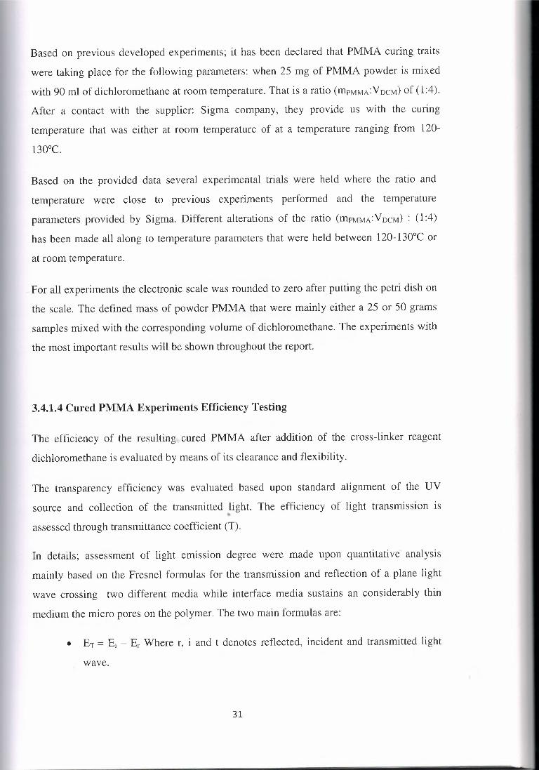
Based on previous developed experiments; it has been declared that PMMA curing traits
were taking place for the following parameters: when 25 mg of PMMA powder is mixed
with 90 ml of dichloromethane at room temperature. That is a ratio (mrMMA:VocM) of (1:4).
After a contact with the supplier: Sigma company, they provide us with the curing
temperature that was either at room temperature of at a temperature ranging from 120-
130°c.
Based on the provided data several experimental trials were held where the ratio and
temperature were close to previous experiments performed and the temperature
parameters provided by Sigma. Different alterations of the ratio (mrMMA: VDCM) : (1 :4)
has been made all along to temperature parameters that were held between 120-130°C or
at room temperature.
For all experiments the electronic scale was rounded to zero after putting the petri dish on
the scale. The defined mass of powder PMMA that were mainly either a 25 or 50 grams
samples mixed with the corresponding volume of dichloromethane. The experiments with
the most important results will be shown throughout the report.
3.4.1.4 Cured PMMA Experiments Efficiency Testing
The efficiency of the resulting cured PMMA after addition of the cross-linker reagent
dichloromethane is evaluated by means of its clearance and flexibility.
The transparency efficiency was evaluated based upon standard alignment of the UV
source and collection of the transmitted light. The efficiency of light transmission is"'
assessed through transmittance coefficient (T).
In details; assessment of light emıssıon degree were made upon quantitative analysis
mainly based on the Fresnel formulas for the transmission and reflection of a plane light
wave crossing two different media while interface media sustains an considerably thin
medium the micro pores on the polymer. The two main formulas are:
• ET= Ei - Er Where r, i and t denotes reflected, incident and transmitted light
wave.
31

32
• A = 1 - T - R where A is negligible; T refers to transmission coefficient and R
for reflection coefficient
The measurements were made using a scalar network analyzer (Agilent HP 80350A
8756A-10 MHz to 40 GHz) shown in the figure below. The arrangement comprises a
sweep generator, an indicator unit and a waveguide reflectometer. The European standards
specifying the measurement methods for the reflectivity of electromagnetic wave (EMA)
absorbers for the normal incident wave were smeared. The ratios of transmitted light /input
source light and reflected beam /input beam from source light were ensued at 35 GHz. The
consequential results are shown in the graphs below.
Figure 3.8: Network analyzer (Agilent HP 80350A 8756A-10 MHz to 40 GHz).
The mechanical performance is evaluated established upon 40 cycles of concaving and
conveying the curvature of the polymer and assessing the elongation through measuring !ıl
by a ruler. Based on the greatness of !ıl 's value the flexibility of the sample is assessed.
The applied formula is:
[rn=40 ı';l]Y = Li - n: Where y refers to average deformation occurred, n: the number of
curvatures performed and m: the total rounds that is to be 40.
3.4.1.5 Porous PMMA Development
In this part, the best recipe resulting with the best cured polymer will be applied all over
again but this time on top of the silicon chip template. Once curing process is

accomplished, the polymer will be peeled out of the silicon and the results is going to be a
porous polymer. The porous PMMA will have pores structure complements
ilicon ship
PMMApowdercovering it andready forDichloromethaneaddition (curingPMMA)
Figure 3.9: an illustration depicting the addition of PMMA on the top of silicon templatebefore curing process
By performing this procedure this may be illustrated as stage G on the developed diagram
of the proposed generic recipe.
-~.•..-~
Figure 3.10: An illustration representing the critical step in the proposed generic recipe;PMMA complementing the pores of silicon template throughout curing process
33

34
3.4.1.6 Characterization of Porous Cured Polymer
The pores morphology of cured porous PMMA polymers will be assessed in details via the
use of Low-End Compact Mini SEM: Scanning electron microscopy (SEM).SEM images
were recorded using AIS 1800C SEI archetypal. The images registered were aimed to
disclose the external surface as well as to show the highly porous morphology of the
developed polymers. PMMA samples were metalized with copper before being introduced
into the microscope; where copper was evaporated from an overhead electrode and
smeared to PMMA sample's then bathed in an acidic solution.
The picture's setup parameters were made under different scales, magnification,
acceleration and working distance (WD) (the distance between the sample and electron
source).
3.4.2 Porous PDMS Polymer Development Phase
3.4.2.1 PDMS Chemical Characteristics
Poly(dimethylsiloxane)bis(3-aminopropyl) or simply PDMS. This polymer chemical
formulation: [H2N (CH2)3Si (CH3)20 [Si (CH3)20]nSi(CH3)2(CH2)3NH2].
Polydimethylsiloxane is industrial manufactured through mixing dimethyldichlorosilane
with water H20 based on this reaction: n Si(CH3)2Ch + n+1 H20 --+ HO[-Si (CH3)20-] n
H + 2nHCl (Jo, Van Lerberghe, Motsegood and Beebe, 2000).However for medical
solicitations; in order to reduce toxicity of the polymerization reaction, chlorine atoms in
the silane precursor may be substituted wish acetate groups. In this way, hydrogen
chloride is avoided and replaced by acetic acid that is less toxic. The resulting polymer
from polymerization process is the one employed in this research. It is known as, H2N
(CH2)3Si (CH3)20 [Si (CH3)20]nSi(CH3)2(CH2) and have the structural formula below:

35
Figure 3.11: Figure displaying the chemical structural formula of Poly (dimethylsiloxane),bis (3-aminopropyl) terminate ("Sigma Aldrich Product Catalog." Sigma Aldrich. N.p.,
2009, Web. 16 Mar. 2015)
PDMS belongs to polymeric organa-silicon's group. It is recognized for its uncommon
rheological (or flow) assets. This latter is optically clear polymer, inert, non-toxic as well
as non-flammable; that make it an appropriate polymer for biological and medical
applications ranging from contact lenses and medical devices to elastomers.
This polymer is employed under the form of viscous liquid (viscoelastic), acts as rubber at
low temperature; having density of 0.98 g/ml at room temperature. After polymerization it
presents a hydrophobic surface (Armani, Liu and Alum, 1999). It has an average molecular
weight M0 -2,500, a viscosity of 50 cSt (lit.), stocked in 50 ml poly bottle. PDMS has a
Flash Point (F) > 234.5°Fand must be employed with personal protecting equipment.
3.4.2.2 PDMS Cross-Linking Reagent: Glutaraldehyde
Glutaraldehyde, a chemical organic compound expressing the molecular formula CH2
(CH2CH0)2 or simply: C5H802and structural molecular formula displayed on figure 3. 12.
This organic is also denoted as glutaral, 1 ,5-P,.entanedione, potentiated acid glutaraldehyde,
sonacide and glutardialdehyde. This item is stored at a temperature 0°C, a molecular
weight of 100.lg/mol., a density 1.016 g/ml and supplied as 0.5% (w/w) solution in water
of grade 1, 25% in H20. This compound is used in sterilization, fixation, cross-linking
processes, as a component of hydraulic fracturing "fracking" fluid as well as other
applications. It is toxic and a sturdy nuisance.

H
o oH
Figure 3.12: Figure displaying the chemical structural formula of Glutaraldehyde ("SigmaAldrich Product Catalog." Sigma Aldrich, N.p., 2009, Web. 16 Mar. 2015)
In this research Glutaraldehyde was used as a cross-linking reagent for curing PDMS.
3.4.2.3 PDMS Curing Recipe Parameters
As in the case of PMMA the same procedure must be applied in PDMS curing procedure.
Lots of papers mentioned different curing methods using catalysis. However, the main
intention was to find a corresponding cross-linker. The first one proposed was poly (£
caprolactone) (PCL), but this one failed to cure PDMS. In the realm of experimental flow;
another basic was applied, the beaker containing liquid PDMS was placed into the oven for
1 hour at 70 °C. But this method failed to cure PDMS.
Gluteraldehyde was a corresponding cross-linker that was able to cure PDMS .
Experiments were held to come out with the best recipe of PDMS curing generating the
clearest and most flexible polymer. In Both cases, heat through usage of a digital oven and
at room temperature; along with alternative values of added cross-linker (glutaraldehyde)
sets of experiments were held.
ı,.Several experiments were held to obtain the targeted results. First of all, a small amount of
sample of PDMS liquid polymer was tested with different amounts of glutaraldehyde to
ensure the formation of the polymer surface and test the degree of solidification of each
volume of cross-linking reagent added.
In the first step in the realm of experimental procedure, the primarily ratio that lunched the
trials for the corresponding recipe initiated from (1: 1). Then, the quantity of PDMS was
increased by adding 1 to the ratio applied.
36

PHOOOll>lST
- PDMSIP1'ffiS
identical sculptured
with identical pores as
the silicon ship.
3.4.2.4 Cured PDMS Experiments Efficiency Testing
The efficiency of the resulting cured PDMS after addition of the cross-linker reagent was
evaluated by the same procedure applied to those of PMMA. The transparency efficiency
using scalar network analyzer and mechanical performance based on tıl evaluation.
3.4.2.5 Porous PDMS Development
In this part, the best recipe resulting with the best cured polymer will be applied all over
again but this time on top of the developed porous PMMA. Poly-dimethyl siloxane
(PDMS) will then be poured on the PMMA surface. And throughput the curing course this
polymer will complement the pores existing on the surface of porous PMMA. This final
resulting porous polymer will be the complement of the complement which is identical to
the porous silicon template.
-=> c::O>,\ u 11i'e final •.pc5lymer
developed from
PDMS or PMHS
Figure 3.13: An illustration showing the last step resulting with the development uf finalporous PDMS identical to silicon scaffold
3.4.2.6 Characterization of Porous Cured Polymer
The same methodology applied for PMMA pores morphology study mentioned earlier will
be applied for the developed porous PDMS.
37

38
CHAPTER4POROUS POLYMER MIMICKING SILICON SCAFFOLD
DEVELOPMENTAL STAGES
This chapter will discuss the different curing experiments held for both PDMS and
PMMA. All along it will show the results from transparency and mechanical efficiency
tests made for each sample developed. The reason we relied on for selecting the
experiment parameters for curing PMMA and PDMS once poured on the top of the defined
scaffold will be highlighted and shown via pictures and graphs. The samples obtained will
be shown. Analysis of the resulting samples from different experiment parameters will be
also revealed. All the experiments held and their results will be shown in graphs and charts.
4.1 PMMA Polymer Curing Process
4.1.1 PMMA Curing Experiments and Resulting Polymers
The table below displays the ratio of mass vs. volume (mPMMA : VDichloromethane)applied in
the experiments performed. Many sets of ratio have been applied in the aim of getting the
clearest cured polymer.
Table 4.1: Table showing the conditions (temperature and r (mPMMA:Voichloromethaııe)) usedfor each experiment
Experiment Sample Temperature (mPMMA:
VDichloromethane)
Experiment 1 Sample 1 "Room temperature (1:6)
Experiment 2 Sample 2 Room temperature (1 :8)
Experiment 3 Sample 3 Room temperature (1 :4) ~
Experiment 4 Sample 4 126°C for 2 min (1 :6)
Experiment 5 Sample 5 Room temperature (1:6)
In the flow Realm the following experiments the following alternatives were made for
experiment 1 :0.25g of PMMA cured with 1.5 ml of Dichloromethane where ratio
(mPMMA: VDichloromethane) is (1 :6) at room temperature; the obtained resulting polymer after
two trials is shown in Figure 4. 1.

c.\l5:}ıı_.,,,ı.
'Rao"" l(..m~• r~
Figure 4.1: Two similar samples of PMMA cured with experiment 1 parameters
The second experiment with the ratio (mPMMA:Voichloromethane) (1:8). 0.25g of PMMA was
cured with 2 ml of cross-linking Dichloromethane at room temperature; the resulting
sample 2 shown in the Figure 4.2.
Figure 4.2: Two PMMA samples cured at room temperature with experiment 2 parameters
The third set of values for experiment 3 claimed and experienced in the aim of a clear
cured polymer were 0.25 g of polymer and 1 ml of Dichloromethane. The ratio
(mPMMA:Voichloromethane) is (1:4).The resulting sample 3 polymer is displayed in the. Figure
4.3.
39

;ıı;.,.,~\.~-L~:ı,•c oı,qo.
(>,'iı.'>3, ...•Rı,o,n~m~•fC.
Figure 4.3: Pictures of two samples obtained after being cured with experiment 3
The intentions of the outcome were aiming for curing polymers at room temperature based
on the fact of avoiding the use of oven and accessibility along to the complications and
drawbacks when dealing with the oven.
The use of the oven was a must to come up with the most efficient curing reaction where
experiment4 was driven using 25 mg and 1.5 ml as a ratio (mPMMA:Voichloromethane) of (1:6)
at 126°C for 2 minutes. The resulting liquid polymers are revealed in the following
pictures.
~-.,.,~ı.S..,..L.{:t(,OC,o~
Figure 4.4: Pictures of cross-linked PMMA in the oven at 126°C for 2 minutes
!l
For experiment 5; 25 mg cured based on ratio (mPMMA:Voichloromethane) = (1:3) with 0.7 ml
of cross-linking DCM at 126°C for 2 minutes. The results of sample 5 are displayed in the
Figure 4.5.
40

,h ••J. _, ....•.• \a"<-~1,-;.."""
I
Figure 4.5: Three different samples resulting from experiment 5 prepared at 126°C for 2minutes
The experiment 5 was repeated for 3 times. The obtained resulting samples shown in the
figure 4.5 gave almost same polymer. The obtained similar results show that this
experiment didn't happen by coincident but rather it is a credible experiment where the
parameters applied are consistent.
After trials, the best sample developed and admitted was sample 5 resulting from
experiment 5. The ratio (mPMMA:Voichloromethane) was (1:3) and 25 mg of PMMA mixed
with 0.7 ml of Dichloromethane at 126 °C for 2 minutes in the oven. The choice was
based on the fact that this recipe generated a clear flexible polymer. Bubbles within the
polymer were a result of the air. Getting rid of these bubbles is achieved throughout the
use of vacuum machine throughout the curing process.
4.1.2 PMMA Curing Experiment Efficiency Evaluation
4.1.2.1 PMMA Transparency Test Analysis and Evaluation
Assessment of light emission degree made upon quantitative analysis based on theil
formulas: E, + Er = Ee and T = 1- R where A to be the absorption coefficient has come up
with the following results.
For sample 1: The ratio (mPMMA:Voichloromethane) applied was (1:6). The obtained resulting
graph of the transmission % of light in terms of incident light is shown in the graph below
41

42
90
100
~~ 1----------------------300 400 soo 600 700 800 900
w4vç lenath ofU(ııml
Figure 4.6: The transmission percentage of the cured polymer by experiment 1 by UVvisible spectrophotometer
For sample 2: with the ratio (mPMMA:VDichloromethane): (1:8). The gotten consequential
diagram of the o/o light transmission in terms of incident light is revealed in the diagram 4.7
100
9S
90
asıol:,-300 400 !JOO 600 700 100 900
wave kııılh9fUl!!!_•l
Figure 4.7: The transmission percentage of the cured polymer by experiment 2 upon anemitted UV wave length
For sample 3: resulting from experiment 3 applying ratio (mrMMA:VDichloromethane) = (1:4).ı,,.
Diagram 4.8 screens the collected the reflected beam results rendered in the drawing of the
o/o light transmission in terms of incident light.

transmıttance %
100
95
90
85sol .ı ,,.,...-ı ,./----.,,.. -,,........_ ...•.•.. ~ ...•
300 400 500 600 700 800 900
ı...~~~~~~~dw~a~v~cMlcnm&!!uıfJ/.(!!!!!lı~~~~~~~~
Figure 4.8: The transmission percentage of the cured polymer by experiment 3 upon anemitted UV wave length
For sample 4: The ratio (mPMMA:Vnichloromethane) applied is (1:6). Diagram below reveals the
coming out far-reached results rendered in the drawing of the% light transmission in terms
of incident light.
9S
90
85
30
.300 400 SOO 600 700 800 900
wave~ oflJ(nııı]
Figure 4.9: The transmission percentage of the cured polymer by experiment 4 upon anemitted UV wave length
For sample 5: The ratio (mPMMA:Vnichloromethane) applied is (1:3). The chart of figure 4.101'
tells the coming the outcome results gotten in the sketch of the % light transmission in
terms of incident light.
43

transmittance %
100
90
8580
9S
300 400 soo 600 700 800 900
wave length ofU(.nnıl
Figure 4.10: The transmission percentage of the cured polymer by experiments 5 upon anemitted UV wave length
In the chart below the% efficiency of the five applied recipe are all depicted in one chart in
the aim of comparison for the best efficient recipe. These results were inserted in the table
below.
9S
Experiment 5tranmıittance %
100
Experiment 4
BS~&O,~
300~ 400 soo 600 700 800 900
__.- wave length ofU(nm]
Experiment 2
Experiment 3
Figure 4.11: The transmission percentage of the cured polymer via the 5 differentexperiments performed upon an emitted UV wave length.
The obtained cured polymer from different experiment ratio (amount of PMMA: Volume
of Dichloromethane) and their average percentage of the efficiency success of obtaining a
clear and transparent polymer are drawn in the table 2 and graph of Figure 4.12.
44

Table 4.2: Table depicting the calculated average o/o efficiency of each recipe applied for adeveloped polymer based on the light reflection basis
Experiment Sample Temperature (mPMMA: VDichloromethaııe) Average o/o of
Efficiency of the
experiment
Experiment 1 Sample 1 Room temperature (1 :6) 92%
Experiment 2 Sample 2 Room temperature (1 :8) 86%
Experiment 3 Sample 3 Room temperature (1 :4) 68%
Experiment 4 Sample 4 126°C for 2 min (1 :6) 81%
Experiment 5 Sample 5 Room temperature (1 :6) 96%
Figure 4.12: Chart depicting the amelioration of efficiency throughout experiment's ratioexperimental realm
4.1.2.2 PMMA Mechanical Performance PMMA Cured Polymers
As described in chapter 2, for testing the mechanical performance is assessed based on the
elongation caused within the polymer without the occurrence of a breakage in the samples.
The applied formula:
Y ['\'n-40
= Li - L..n~ ill Where Li denotes the diameter measured by a ruler between the
extremities of the samples developed. And lıl=Lf - Li where lıl is the elongation that
resulted after 40 sets of concaving and conveying deformation. The diameter of each cured
PMMA sample will be measured before and after the 40 deformation cycle. The
45

measuring the
diameter of the
polymer after
deformation
executed.
subsequent results after being replaced in the formula and averaged are listed in the table
below.
Ruler used for
Figure 4.13: Picture showing the measurements of the diameter of the polymer afterdeformation realized
Table 4.3: Table showing the % Average deformation ensued for several trials for eachdeveloped polymer
Polymers cured % Average deformation occurred
Sample 1 78 % with no cracking
Sample 2 33% numerousbristles of crakes
Sample 3 3 % sample cracks at ıo" trial
Sample 4 55% some bristles of crakes
Sample 5 88% with no cracking
Figure 4.14: A graph depicting the% average deformation taking place in the polymerafter deformation
46

(18) 86%
4.1.2.3 PMMA Curing Polymer Experiment Selected
fapcrinmıt I Sanıpk l
E~iment2 Samplc2
Experiment J Sarop!e3
Expcriment4 Sanıple4
=ı,mruııır, ·~tt':i
L,,_. - .. ,j_ . '.=J!.ra~;
(16) 92%
(1:4) 68%
. '(I'SJ •. T ..=• .... ı .. ı
Sample 5 presents thebestresults for both lighttransmission efficiencyand thebest capability to afforddeformation.
Figure 4.15: Assessment for the most efficient curing experiment to be applied tocomplement pores on the silicon chip
From the obtained results from the test applied and through comparison; the carefully
selected recipe to be applied when curing the polymer on top of the silicon chip is
experiment 5 where the ratio (mPMMA: Vctichloromethane) is (1 :3) at the experiment must be
held at 126°Celsius for 2 minutes.
4.1.3 Development of Porous PMMA by Application of Selected Experiment
Once it was agreed on the corresponding, most accurate and efficient curing recipe for
powder PMMA; experiment 5 with ratio (J :3), it was time for applying the experiment on
top of the silicon chip template.
In this part, the approved experiment 5 is applied. The silicon template chip was covered
with 25 mg of PMMA and then dropped into a beaker containing 75 ml of
Dichloromethane. This mixture was whisked vigorously with a spatula for almost 4
minutes till the dichloromethane was uniformly distributed throughout PMMA powder.
The uniformed mixture was inserted in the oven prepared and settled at 126° C. The
mixture is left for 2 minutes in the oven before being removed and left for cooling.
47
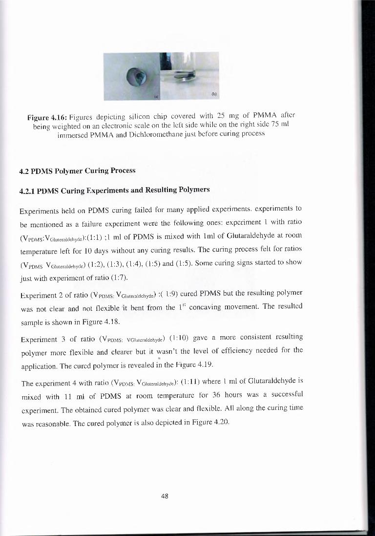
(I)(b)
Figure 4.16: Figures depicting silicon chip covered with 25 mg of PMMA afterbeing weighted on an electronic scale on the left side while on the right side 75 ml
immersed PMMA and Dichloromethane just before curing process
4.2 PDMS Polymer Curing Process
4.2.1 PDMS Curing Experiments and Resulting Polymers
Experiments held on PDMS curing failed for many applied experiments. experiments to
be mentioned as a failure experiment were the following ones: experiment 1 with ratio
(VPDMs:VGıuteraldehyde):(1:1) ;1 ml of PDMS is mixed with 1ml of Glutaraldehyde at room
temperature left for 10 days without any curing results. The curing process felt for ratios
(VPDMS VGıuıeraldehyde) (1:2), (1:3), (1:4), (1:5) and (1:5). Some curing signs started to show
just with experiment of ratio (1 :7).
Experiment 2 of ratio (VPDMS: VGluteraldehycte) :( 1:9) cured PDMS but the resulting polymer
was not clear and not flexible it bent from the I" concaving movement. The resulted
sample is shown in Figure 4.18.
Experiment 3 of ratio (VPDMS: VGluteraıcıehycte) (1: 10) gave a more consistent resulting
polymer more flexible and clearer but it wasn't the level of efficiency needed for theil
application. The cured polymer is revealed in the Figure 4. 19.
The experiment 4 with ratio (VPDMS VGluteraldehyde): (1: 11) where 1 ml of Glutaraldehyde is
mixed with 11 ml of PDMS at room temperature for 36 hours was a successful
experiment. The obtained cured polymer was clear and flexible. All along the curing time
was reasonable. The cured polymer is also depicted in Figure 4.20.
48

Figure 4.17: Pictures depicting experiment 1 that failed to give the desired results forcuring PDMS
Figure 4.18: Pictures depicting the cured polymer with the experiment of ratio (VPDMSVGluteraldehyde): (1:9)
Figure 4.19: Pictures depicting the cured polymer with the experiment of (VpoMs:VGluteraldehyde) ratio equal (1: 10)
49
Figure 4.20: PDMS cured at room temperature for (VrDMs: Yrnuteraldehycte): (1:11) ratioapplication
The best experiment obtained and elected for application to complement the PMMA pores
was the one with ratio ( 1: 11) where 1 ml of PDMS is cured with 11 ml of
Dichloromethane at room temperature for 36 hours. The optimal was grounded on the
detail that this experiment produced a reasonable clear flexible polymer corresponding for
an application. Bubbles within the polymer were eliminated through whisking for 20 min
the polymer and curing agent once mixed.
4.2.2 PDMS Curing Experiment Efficiency Evaluation
4.2.2.1 PDMS Transparency Test Analysis and Evaluation
For experiment agreed at where ratio (VPDMs: VGluteralctehycte) applied is (1: 11), the results
gotten after transparency test were depicted in the graph below. The results of the
transmission % of light in terms of incident light are shown in the following graph.
50

ıoo9S
9()
••
,lOO ,MıO ,oo 600 100 IIOO l>CIO••••..• ıcııım cı(U(ıııııl
Figure 4.21: The transmission percentage of the cured PDMS upon an emitted UV wavelength 680 nm
The graph strained upward clearly highlights the resulting efficiency for light transmission
to be about 93% efficiently transparent cured polymer. The results of the transmission % of
light in terms of incident light are satisfactory.
4.2.2.2 Mechanical Performance of PDMS Cured Polymers
The 40 sets of 20 concaving bending followed by other 20 conveying movements of
PDMS cured monitored by elongation measurements gave the following results. The
obtained results made throughout numerical analysis were 79 % with no cracking which is
somehow a satisfying result.
Based on the efficiency test results; the judgment to apply the selected experiment with
ratio (VPDMs: VGluteraıctehycte): (1: 11) for curing PDMS is going to be applied on the top of the
PMMA cured porous polymer.
4.2.3 Development of Porous PSMS by Application of Selected Experiment
In this fragment of the research PDMS and Gluteraldehyde were mixed based on the ratio
(VPDMs: Vrnuteraldehycte):(1:11) where 2 ml of PDMS were cured with 22 ml of the curing
reagent and whisked for 25 minutes. Just after the start of air bubbles evaporation the
porous PMMA was dropped on the mixture experiment and left for 36 hours at room
temperature. Once cured the two polymers were peeled out from each other. The taken off
PDMS has the same texture as the silicon sample.
51

-~.,D
.-ı,. Silicon•••••••.• PMMA.- .• Ohotorcsist-fDMS/PHMS
-PD1'.1S cured on top ofthe porous PM:MA tocomplement its pores
Figure 4.22: An illustration clarifying the step of generating porous PDMS step on thegeneric experiment diagram
52

CHAPTERSRESULTS AND DISCUSSION
This chapter will present the development of porous PMMA complementing silicon
template and porous PDMS complementing PMMA while being cured with the
experimental parameters settled in chapter four. The resulting polymers sample will be
shown through pictures and compared to top of pen or a coin to show their true scale. The
microstructure assessment of porous PMMA and PDMS will be presented. At the end a
comparison between typical porous polymer fabrication method and the proposed
technique applied in the thesis will be highlighted.
5.1 Development of Porous PMMA
As mentioned in chapter four the selected experiment parameters are the one applied in
experiment five. The silicon template chip was covered with 25 mg of PMMA and then
dropped into a beaker containing 75 ml of Dichloromethane. This mixture was whisked
vigorously with a spatula for almost 4 minutes till the dichloromethane was uniformly
distributed throughout PMMA powder. The uniformed mixture was inserted in the oven
prepared and settled at 126° C. This step may be illustrated as stage E from the diagram of
the proposed generic recipe. The mixture was left for 2 minutes in the oven before being
removed and left for cooling.
53

F#C
Figure 5.1: Illustration clarifying the resulting porous PMMA on the generic experimentdiagram
After cooling the PMMA sample is peeled off the silicon scaffold. This step is stage F of
the diagram of the proposed recipe. The developed porous PMMA is shown in figure 5.2.
This sample will be compared to the top of a pen in order to show and approximate its true
scale.
Figure 5.2: An illustration depicting the porous polymer PMMA
54

Figure 5.3: Picture showing the true scale of porous PMMA compared to a pen
Compared to a pen the true scale of the resulting polymer can be averaged to be A = rrr2.
Where r is 1.8 cm and A= rr(l.8)2 = 10.2 cm".
5.1.1 PMMA Morphology and Microstructure Properties Analysis
After peeling the PMMA from the top of the silicon, cooling and undergoing treatment
with copper; the sample were examined via SEM where the pores were assessed. The
pictures were registered under different dimensions. Where figure 5.4 depicts the pores of
the PMMA sample at the scale of 5 µm, magnification of 6KV, an acceleration of 20KV
and a working distance (WD) sets at 25,2mm. Figure 5.6 shows other images taken at
different angels to show the aspects of the pores was achieved throughout increasing the
scale up to lOµm and dropping the magnification to 3KV. The last registered image 5.7
was obtained by enlarging the scale up to 50µm for extra details and decrementing the
magnification up to lKV. Other sets of pictures were also taken from different angle to
show different parts of the porous site of PMMA sample.
55

Figure 5.4: Picture taken by the SEM for porous PMMA
Figure 5.5: Picture taken by the SEM for porous PMMA from different angles
56

57
Figure 5.6: SEM image of porous PMMA at 50µm
Figure 5.7: SEM image of porous PMMA at lüµm
The size of the pores showed in the Figur•.e 3.21 ranges among nm and 2,5µm which is
analogous with the size of the pores of the silicon chip that it was intended to complement
it. All along; in the Figure 3.22 the distance measured amongst the pores of PMMA was
2,5µm over and above 20,8µm that is again approving the morphology of silicon pores. In
the after scanned presented image, the pores were not arranged in a coordinated manner
and not uniform; they were pores of diverse size guaranteeing again that these pores are
the complement of the silicon template.

In this part of the research PDMS and Gluteraldehyde were mixed based on the ratio
(VPoMs: Vrnuteraldehyde) that is (1:11) where 2 ml of PDMS were cured with 22 ml of the
curing reagent and whisked for 25 minutes. Just after air bubbles starts evaporation the
porous PMMA developed earlier was dropped on the mixture experiment and left for 36
hours at room temperature. This is considered to be stage G on the diagram of the generic
recipe. Once cured the two polymers were peeled out from each other. The taken off
PDMS has the same texture as the silicon sample. A picture of the developed PDMS
sample after being peeled from the surface of porous PMMA is shown in figure 4.8.
Figure 5.8: On the left the mold PMMA, on the right the completing porous cured PDMSsimilar to silicon
58

Figure 5.9: PDMS sample size compared with the top of the pen
5.2.1 PDMS Morphology and Microstructure Properties Analysis
After detaching the PDMS from the top of the PMMA after 3 days, the sample was treated
with copper. Then, the sample's pores were inspected by means of SEM. The PDMS
porosity was measured at the same scale 1 Oµm but with different magnifications value; one
is set at 5kV, one at 3kV and one at 20kV. The pores sizes altered between few nm all
along to 2µm. The remarkable point to be taken into consideration is that the sample under
study has the same texture as well as the porosity of that of the silicon sample. The below
figures show a non-uniform and non-coordinated repartition of the pores morphology that
again the case of the silicon chip.
59

Figure 5.10: PDMS SEM images at 5 KV
Figure 5.11: PDMS SEM images at 3 KV
60

61
5.3 Novelty of the Generic Recipe: Results of Comparison with Typical Applied
Porous Polymer Fabrication
Previous curing official process for PMMA and PDMS polymers supplied by Sigma
Aldrich were lacking existence. The experimental procedures for curing them were
prepared using the Sylgard 184 Silicone Elastomer Kit that is a ready package with a clear
instruction for curing parameters. In this research we were able to develop the curing
parameters for both polymers PMMA and PDMS that may be applied for polymers
obtained from any supplier.
The other novelty of this work was the easiness in the procedure and the accessibility to
pores morphology. Previously each porous manufacturing technique use to necessitate a
special manufacturing process. The old applied manufacturing were either gas foaming,
phase separation including immersion precipitation, chemically and thermally induced
phase separation, small liquid drops templating, bio-continuous micro-emulsion
templating, colloid crystal templating, templating via self-assembled structures or
molecular imprinting. Each of these methods necessitates a special temperature, pressure,
equipments all along to cross-linker. The costs encountered with these techniques are very
high. While the proposed generic recipe coast are very low since no equipments and
special machine are needed.
The process is just straight forward consisting of two micro-molding steps while other
techniques necessitate many phase for developing the porous polymer.
This technique offers accessibility to the pores morphology and size which is in nano
scale.

Table 5.1: Table showing the compared factors of the generic recipe proposed and typicalmethods
~
fac9n Otnffk Redpr Olber TttlıntqaH Applled
ıoCom LOW COST IDGH COST/EXPENSIVE
E41mpmniı "°'9v.l Sil«ıa, dı.lp IJ'Kd II I E4dı OIi~ ıı«aıiweı ~ıcıfruld ı:aıdıiK 111.ıl eqıı.lpııımıı
Ttı:ac-or ıııa•• raeturtııı Twııı to 11ırtt d.ı.r, IAııg timeof ınmuf-.mıg
Enftnnmcııt CJ,mıiıtry lab Sp«ially eqııipped labQııııori.n
Type- •I polymers lıay ıypc oC pıl,oıas Specu1 l)JIC ıırpıı1yıııcn
Maauraıen rtııı PNı,(!tlıt. Vı:sy ~. ~ torwırd Vı:r,~'4lıeKd QII two-miaomıoldiııı..--
Poreıau Nıao-ıcı1e Dq,mdı oıı ıht.mldı.od applied
Pnsıun fHtor Noc ma imo coıuidmıiaa An iıııp,cımDI facı« dll1 ddiımÜlt pgnniıy ıııaqılı,oloır
Pressure is another factor to be taken into consideration during the fabrication of the
porous polymer. Each of the processes used for fabrication of porous polymer are
conducted at a different pressure in order to obtain the required porosity. For the generic
recipe, the pressure factor will be neglected; the pores within the surface of the polymer
could be formed at a specific pressure. Hence, no need for complicated calculations in
order to achieve a pressure to volume ratio within the surface of the structure
Previous methods intend to develop porous polymers with a porosity size and shape
depends on the application and manufacturing technique. In the proposed novel generic••
recipe the porosity morphology depends on one factor: the porosity morphology of the
porous silicon scaffold. The generic recipe is just a straight forward method composed of
two micro molding steps that does not necessitate a special environment nor expensive
equipments.
62
CHAPTER6CONCLUSION
6.1 Conclusion
In this thesis it was aimed to develop a method or more critically a generic recipe that can
be applied to specific polymers to texture their surface with any intended porous structure.
This porous structure is achieved by two processes the first one when complementing the
pores of silicon chip that worked out as a template and that the final polymer will have the
same identical pores. The second step is to complement the obtained polymer.
This method helps to dispense the usage of the methods widely used to develop pores
structure on any polymer's surface. Another advantage is that this procedure costs are less
than any of the typical applied method. Also it does not need any electrolyte or machine
just the silicon template.
The curing recipes were under construction and trials, experiments done and applied
proved that the best recipe for curing PMMA was the usage of 25 mg of PMMA under
powder form and 7 ml of Dichloromethane at 126°C for 2 min in the oven. This recipe has
resulted usage and applications.
The curing of PDMS was achieved via application of the recipe with a ratio (VPDMs:
VGluteralctehycte) (1: 11) at room temperature for three days where the curing reagent was
Glutaraldehyde. The resulting cured polymer was on the level of the expectations from
both clearance (transparency) and flexibility characteristics. This cured polymer on top of
porous PMMA resulted with a conventional porous PDMS stamped with similar pores to
those of the silicon template.
The aim and intentions that enthusiast toward the thought of this procedure is that silicon
when implanted into the human body may present some compatibility issue while the
three mentioned polymers has been proved to be compatible. And lots of newly diverging
applications in biomedical are inducing the use of PDMS.
The applied process was a simple, direct forward and flexible based on the fact that
developed porous polymers may owe several pores morphology and the morphology may
63

be changed as the application demands. This porosity alteration may be achieved simply
by changing the matrix of porous silicon chip. These samples may be used in all
biomedical domains and applications related to biomedical field; from contact lenses
against UV lights to polymeric uterus and many other applications that will help to
improve the human life.
As a conclusion; PDMS, PMMA and PDMS are good candidates for several biomedical
application and porous structure of these polymers will make an innovation in the
biomedical world. This proposed generic method is very easy to be applied and very less
costing compared to other applied methods.
6.2 Recommendation and Future Work
Infertility is fundamentally the inability to conceive offspring. The causes of infertility
either sex refer to some DNA damage, hypothalamic-pituitary factors, environmental
factors, and other general factors such as diabetes mellitus, thyroid disorders, and adrenal
disease. In vitro fertilization (Lopez-Saucedo et al., 2014) provides a solution for the
formation of a zygote where an egg is fertilized by sperm outside of the body.
Microporous polymers will serve as a substrate for in vitro fertilization providing a large
surface for multiple trials due to the large number of pores within the polymer surface.
Each microporous polymer will reflect a culture medium that consists of carbohydrates,
macromolecules, amino acids, vitamins, and antibiotics. The sperm and the ovum may be
placed selectively in the same pore. Upon fertilization the early embryos (zygote) have a
simple physiology and maintain low levels of oxidative metabolism. Amino acids are
important regulators of mammalian pre-implantation development. Carboxylic acids and
amino acids are used as energy sources prior to the embryonic genome. Moreover,
macromolecules like proteins maintain the stability of the cell membrane while vitamins
play a role as antioxidants. The pores within the polymer are regularly supplemented with
antibiotics to prevent bacterial contamination. The osmotic pressure of the medium should
resemble the osmotic pressure of the oviduct fluid. Similarly, the PH must be between 7.2
and 7.4. Under these conditions, the zygote will then be transferred to the mother's uterus
(Lebrun, Camargo, and Correa, 1988).
64

Other application may be the polymeric uterus. Female infertility problems that a good
number of woman face every single year around the world, is frequently associated with
complications occurring in the ovaries, fallopian tubes all along with uterus. Once
fertilization takes place and zygote develops; the latter will be pushed along the Fallopian
tube up until attaining the uterine lining where it will find a place in the uterine wall to
implant itself. This place will stands as nourishment place throughout the whole period of
pregnancy. In case of any problems falling in this uterus section due to any factor
associated to the uterine tissue, the pregnancy will be threatened. The developed recipe of
porous polymer will solve the problem where it's going to be used a nourishment source
for the damaged cellular parts of the uterus.
minus
Figure 6.1: Anatomical representation of the uterus (Elias, Markovits, Reshef, van derZee, and Cohen, 1990)
Subsequent to any accident at the cellular level, a sample of the uterus may be prepared by
means of the liquid polymers; an entire polymeric uterus surface may be fabricated
duplicating the normal female uterus throughout the application of the generic recipe
developed throughout this work. Applying the upper steps of the previous general recipe
synchronically, the first step considers curing the liquid polymer over a biopsy of the
patient uterus treated in a specific container respecting all hygiene, purity, temperature
among other factors confirming the expanse of the natural human uterus. Once cured, the
65

polymeric surface will be peeled off gently to form the uterus complementing template.
This latter sample will be complemented in turns by curing the chosen polymer on its
surface. Once cured, the obtained polymer is just a copy sample textured with the female
cells porosity ready to be implanted in the mother female. Knowing that each polymer has
a specific period of degradation, the choice of the implanted polymer must be very critic
to exceed the ten months in the aim of covering the whole period of pregnancy.
66

67
REFERENCES
Aad, G., Abajyan, T., Abbott, B., Abdallah, J., Khalek, S. A., Abdelalim, A., Abdinov, O.,
Aben, R., Abi, B., and Abolins, M. (2012). Observation of a new particle in the search for
the Standard Model Higgs boson with the ATLAS detector at the LHC. Physics Letters B,
716(1), 1-29.
Aad, G., Abbott, B., Abdallah, J., Khalek, S. A., Abdinov, O., Aben, R., Abi, B., Abolins,
M., AbouZeid, O., and Abramowicz, H. (2014). Search for squarks and gluinos with the
ATLAS detector in final states with jets and missing transverse momentum using s= 8 TeV
proton-proton collision data. Journal of high energy physics, (9), 1-52.
Adiga, S. P., Jin, C., Curtiss, L. A.. Monteiro-Riviere, N. A., and Narayan, R. J. (2009).
Nanoporous membranes for medical and biological applications. Wiley Interdisciplinary
Reviews: Nanomedicine and Nanobiotechnology, 1 (5), 568-581.
Ashruf, C., French, P., Bressers, P., and Kelly, J. (1999). Galvanic porous silicon formation
without external contacts. Sensors and Actuators A: Physical, 74(1), 118-122.
Aubert, B., Boutigny, D., Gaillard, J.-M., Hicheur, A., Karyotakis, Y., Lees, J., Robbe, P.,
Tisserand, V., Palano A., and Pompili, A. (2002). Study of time-dependent CP-violating
asymmetries and flavor oscillations in neutral B decays at the Y (4 S). Physical Review D,
66(3), 032003.
Bar-Cohen, Y. (2004). Electroactive polymers (EAP) as actuators for potential future
planetary mechanisms. Paper presented at Jhe Evolvable Hardware, 2004. Proceedings.
2004 NASA/DoD Conference on.
Barillaro, G., Nannini, A., and Piotto, M. (2002). Electrochemical etching in HF solution
for silicon micromachining. Sensors and Actuators A: Physical, 102(1), 195-201.
Bassiri-Gharb, N. (2008). Piezoelectric MEMS: materials and devices Piezoelectric and
Acoustic Materials for Transducer Applications (pp. 413-430): Springer.

Benowitz, N., Blum, A., Braithwaite, R., and Castro, F. (2014). Tobacco use among US
racial/ethnic minority groups-African Americans, American indians and Alaska natives,
Asian Americans and Pacific islanders, and Hispanics: a report of the surgeon general.
Bhatti, K. P., Chaudhary, S., Pandya, D. K., and Kashyap, S. C. (2008). Is Transition Metal
Incorporated ZnO an Intrinsic Ferromagnetic Semiconductor? Paper presented at the MRS
Proceedings.
Boughaba, S., and Wang, K. (2006). Fabrication of porous silicon using a gas etching
method. Thin Solid Films, 497(1), 83-89.
Carroll, G. T., Turro, N. J.and Koberstein, J. T. (2010). Patterning dewetting in thin
polymer films by spatially directed photocrosslinking. Journal of colloid and interface
science, 351 (2), 556-560.
Chinwalla, A. T., Cook, L. L., Delehaunty, K. D., Fewell, G. A., Fulton, L. A., Fulton, R.
S., Graves, T. A., Hillier, L. W., Mardis, E. R., and McPherson, J. D. (2002). Initial
sequencing and comparative analysis of the mouse genome. Nature, 420(6915), 520-562.
Dong, X., J. Chen, Y. Ma., Wang, J., Chan-Park, M. B., Liu, X., Wang, L., Huang, W.,
and Chen, P. (2012). Superhydrophobic and superoleophilic hybrid foam of graphene and
carbon nanotube for selective removal of oils or organic solvents from the surface of water.
Chemical Communications, 48(86), 10660-10662.
Durnitriu, S. (2001). Polymeric biomaterials, revised and expanded: CRC Press.
Elias, D., Markovits, D., Reshef, T., van der Zee, R., and Cohen, I. R. (1990). Induction
and therapy of autoimmune diabetes in the non-obese diabetic (NOD/Lt) mouse by a 65-ııı
kDa heat shock protein. Proceedings of the National Academy of Sciences, 87(4), 1576-
1580.
Fetter, A. L., and Walecka, J. D. (2003). Quantum theory of many-particle systems:
Courier Corporation.
Fujiwara, K., Okada, M., Takeda, S., and Matsumoto, N. (2014). A novel strategy for
preparing nanoporous biphasic calcium phosphate of controlled composition via a
modified nanoparticle-assembly method. Materials Science and Engineering: C, 35, 259-
266.
68

Gad-el-Hak, M. (2005). MEMS: introduction and fundamentals: CRC press.
Ismail, R. S., Baldwin, R. L., Fang, J., Browning, D., Karlan, B. Y., Gasson, J. C., and
Chang, D.D. (2000). Differential gene expression between normal and tumor-derived
ovarian epithelial cells. Cancer research, 60(23), 6744-6749.
Jacobs, S. E., Lamson, D. M., George, K. S., and Walsh, T. J. (2013). Human rhinoviruses.
Clinical microbiology reviews, 26(1), 135-162.
Jian, F., Zhang, Y., Wang, J., Ba, K., Mao, R., Lai, W., and Lin, Y. (2012). Toxicity of
biodegradable nanoscale preparations. Current drug metabolism, 13(4), 440-446.
Jiang, Y., Jahagirdar, B. N., Reinhardt, R. L., Schwartz, R. E., Keene, C. D., Ortiz
Gonzalez, X. R., Reyes, M., Lenvik, T. , Lund, T., and Blackstad, M. (2002). Pluripotency
of mesenchymal stem cells derived from adult marrow. Nature, 418(6893), 41-49.
Karasiııski, P., Tyszkiewicz, C., Rogozinski, R. , Jaglarz, J., and Mazur, J. (2011). Optical
rib waveguides based on sol-gel derived silica-titania films. Thin Solid Films, 519(16),
5544-5551.
Khaira, A., Gupta, A., Rana, D. S., Gupta, A., Bhalla, A., and Khullar, D. (2009).
Retrospective analysis of clinical profile prognostic factors and outcomes of 19 patients of
emphysematous pyelonephritis. International urology and nephrology, 41(4), 959-966.
Konaganti, V. K., and Madras, G. (2010). Ultrasonic degradation of poly (methyl
methacrylate-co-alkyl acrylate) copolymers. Ultrasonics sonochemistry, 17(2), 403-408.
Kronfeld, A. S., Tschirhart, R. S., Al-Binni, U., Altmannshofer, W., Ankenbrandt, C.,
Babu, K., Banerjee, S., Bass, M., Batell, B., and Baxter, D. V. (2013). Project X: physics
opportunities. arXiv preprint arXiv: 1306.5009.
Kulkarni, R., Pani, K., Neuman, C., and Leonard, F. (1966). Polylactic acid for surgical
implants. Archives of Surgery, 93(5), 839-843.
Kumari, S., Bugaut, A., Huppert, J. L., and Balasubramanian, S. (2007). An RNA G
quadruplex in the 5' UTR of the NRAS proto-oncogerıe modulates translation. Nature
chemical biology, 3(4), 218-221.
69

Lee, D. C., and Jang, L. W. (1996). Preparation and characterization of PMMA-clay
hybrid composite by emulsion polymerization. Journal of Applied Polymer Science, 61 (7),
1117-1122.
Lehmann, V., and Föll, H. (1990). Formation mechanism and properties of
electrochemically etched trenches in n-type Silicon. Journal of the Electrochemical
Society, 137(2), 653-659.
Luo, C., Meng, F., and Francis, A. (2006). Fabrication and application of silicon-reinforced
PDMS masters. Microelectronics journal, 37(10), 1036-1046.
Mathew, F. P., and Alocilja, E. C. (2005). Porous silicon-based biosensor for pathogen
detection. Biosensors and bioelectronics, 20(8), 1656-1661.
Mavromatidis, L. E., Mankibi, M. E., Michel, P., and Santamouris, M. (2012). Numerical
estimation of time lags and decrement factors for wall complexes including Multilayer
Thermal Insulation, in two different climatic zones. Applied Energy, 92, 480-491.
Moreno, S. G., Sutton, A. J., Ades, A., Stanley, T. D., Abrams, K. R., Peters, J. L., and
Cooper, N. J. (2009). Assessment of regression-based methods to adjust for publication
bias through a comprehensive simulation study. BMC medical research methodology, 9(1),
2.
Müller, R., Anders, N., Titus, J., and Enke, D. (2013). Ultra-thin porous glass
membranes-An innovative material for the immobilization of active species for optical
chemosensors. Talanta, 107, 255-262.
Murugan, R., and Ramakrishna, S. (2007). Design strategies of tissue engineering scaffoldsil
with controlled fiber orientation. Tissue engineering, 13(8), 1845-1866.
Nischang, I. (2013). Porous polymer monoliths: morphology, porous properties, polymer
nanoscale gel structure and their impact on chromatographic performance. Journal of
Chromatography A, 1287, 39-58.
Ozaki-Kuroda, K., Yamamoto, Y., Nohara, H., Kinoshita, M., Fujiwara, T., Irie K., and
Takai, Y. (2001). Dynamic localization and function of Bnilp at the sites of directed
growth in Saccharomyces cerevisiae. Molecular and Cellular Biology, 21(3), 827-839.
70

Palestino, G., Legros, R., Agarwal, V., Perez, E., and Gergely, C. (2008). Functionalization
of nanostructured porous silicon microcavities for glucose oxidase detection. Sensors and
Actuators B: Chemical, 135(1), 27-34.
Pavesi, L., Dal Negro, L., Mazzoleni, C., Franza, G., and Priolo, F. (2000). Optical gain in
silicon nanocrystals. Nature, 408(6811), 440-444.
Portalski, S. (1963). Studies of falling liquid film flow film thickness on a smooth vertical
plate. Chemical engineering science, 18(12), 787-804.
Ravichandran, K. S. (2010). Find-me and eat-me signals in apoptotic cell clearance:
progress and conundrums. The Journal of experimental medicine, 207(9), 1807-1817.
Redenbach, M., Kieser, H. M., Denapaite, D., Eichner, A., Cullum, J., Kinashi H., and
Hopwood, D. (1996). A set of ordered cosmids and a detailed genetic and physical map for
the 8 Mb Streptomyces coelicolor A3 (2) chromosome. Molecular microbiology, 21(1), 77-
96.
Sacchetin, P. S. C., Morales, A. R., Moraes, A. M., and e Rosa, P. d. T. V. (2013).
Formation of PLA particles incorporating l 7a-methyltestosterone by supercritical fluid
technology. The Journal of Supercritical Fluids, 77, 52-62.
Sailor, M. J., and Park, J. H. (2012). Hybrid nanoparticles for detection and treatment of
cancer. Advanced materials, 24(28), 3779-3802.
Salemo, A., Zeppetelli, S., Di Maio, E., Iannace, S., and Netti, P. (2011).
Processing/structure/property relationship of multi-scaled PCL and PCL-HA composite
scaffolds prepared via gas foaming and ,NaCl reverse templating. Biotechnology and
bioengineering, 108(4), 963-976.
Sammak, A., Azimi, S., Mohajerzadeh, S., Khadem-Hosseini, B., and Fallah-Azad, B.
(2007). Silicon nanowire fabrication using novel hydrogenation-assisted deep reactive ion
etching. Paper presented at the Semiconductor Device Research Symposium, 2007
International.
Schmalz, G., and Galler, K. (2011). Tissue injury and pulp regeneration. Journal of dental
research, 90(7), 828-829.
71

Schmitt, E. E., and Polistina, R. A. (1969). Polyglycolic acid prosthetic devices: Google
Patents.
Shtil'man, M. I. (2003). Polymeric biomaterials (Vol. 15): VSP.
Silverstein, R. M., Webster, F. X., Kiemle, D. and Bryce, D. L. (2014). Spectrometric
identification of organic compounds: John Wiley & Sons.
Sigma Aldrich Product Catalog. (2009). Sigma Aldrich, N.p..Retrieved March 16 2014,
from www.http://www.sigmaaldrich.com/catalog/papers/23930412.
Solomos, S., Kallos, G., Mavromatidis, E., and Kushta, J. (2012). Density currents as a
desert dust mobilization mechanism. Atmospheric Chemistry and Physics, 12(22), 11199-
11211.
Syverson, D. J., and Novak, R. E. (1990). HF gas etching of wafers in an acid processor.Springer-Verlag Heidelberg.
Tsivintzelis, I., Musko, N. E., Baiker, A., Grunwaldt, J. D., and Kontogeorgis, G. M.
(2013). Experimental determination and modeling of the phase behavior for the direct
synthesis of dimethyl carbonate from methanol and carbon dioxide. The Journal of
Supercritical Fluids, 84, 155-163.
Wang, F., Zhou, D., Ma, S., Yu, H., Li, P., and Yang, Z. (2011). Preparation and
luminescent properties of Eu 2+ doped Sr 3 La (PO 4) 3 phosphor. Journal of Alloys and
Compounds, 509(14), 4824-4827.
Wu, H., Hu, Y., Wang, Y., and Mou, Z. (2010). Influence on the long afterglow properties
by the environmental temperature. Journal of Luminescence, 130(1), 127-130.
Xing, G., Mathews, N., Sun, S., Lim, S. S., Lam, Y. M., Gratzel, M., Mhaisalkar S., and
Sum, T. C. (2013). Long-range balanced electron-and hole-transport lengths in organic
inorganic CH3NH3PbI3. Science, 342(6156), 344-347.
72