Range of Coriolis Mass Flow Meters - Rheonik
7
The World's Most Versale Range of Coriolis Flowmeters
-
Upload
hile-controls-of-alabama-inc -
Category
Engineering
-
view
161 -
download
7
Transcript of Range of Coriolis Mass Flow Meters - Rheonik

The World's Most Versatile Range of
Coriolis Flowmeters

T H E C O R I O L I S E X P E R T SC o n t a c t u s : w w w . r h e o n i k . c o m
T H E C O R I O L I S E X P E R T SC o n t a c t u s : w w w . r h e o n i k . c o m
5. Fuel OilRheonik Coriolis mass flow meters are utilized as both transfer meters and check meters for fuel oil deliveries
6. Process FeedRheonik Mass flow meters are perfect for batching and continuous feed processes
7. Hydrogen FuelingRheonik are the world leader in high pressure meters for Hydrogen dispensing
3. Custody TransferInherent high accuracy is a key requirement for CT
4. Embedded SystemsThe small footprint of Rheonik embedded rail mount transmitters and in line sensors are a favourite solution for OEM’s
1. AdhesivesNo moving parts to be plugged or fouled
2. BitumenRheonik meters operate at continuous high temperature while providing high accuracy measurement
1
2
3
8
9
4
5
7
6 RHEONIK IN GLOBAL INDUSTRYOn this page are just a few examples of Rheonik meter installations from around the world. Rheonik meters are used every day in just about every industry globally, providing real time input into process and measurement systems.
Reliability is key – Rheonik Coriolis meters have no moving parts to wear or plug and are suited to both gas and liquid streams. The ability to work across a wide range of flow rates and process conditions dramatically lowers installation and operation costs.
Safety is built in to all systems. Low power usage makes all Rheonik meters intrinsically safe and all meters are proof tested
to 1.5x their maximum operating pressure before shipment.
With highly accurate measurement performance and high pressure capabilities, Rheonik meters are a natural choice for so many applications and quickly provide payback through improved product quality and greatly reduced maintenance.
Whether used for transfer, batching, process feed or control, Rheonik meters can provide online flow and density measurement. Like all of our customers, you can be assured of a value-for-money flow measurement solution from Rheonik for every application.
13. Oilfield ServicesRheonik high pressure meters provide close-to-the-well flow measurement with high turndown capability and fluid independence for the utmost in deployment flexibility
14. Fuel FeedRheonik meters are found in ships, turbine sets, jet engine test stands, internal combustion engine test cells and dynamometers worldwide
8. Leak DetectionMission critical systems like LD count upon the reliability of Rheonik Coriolis meters
9. TerminalingThe dependable flow measurement from Rheonik flow meters leads to successful and reliable product movements in terminal complexes
10. OffshoreRheonik meters are rugged and built with materials necessary for offshore use
12. Onshore Oil ProductionCoriolis meters are ideal for measuring well production flows and oil and water streams from test separators in the field
10
12
11
13
14 1515. Polyurethane ProductionAccurate measurement performance and high pressure capability of Rheonik meters make them a natural choice for any polyurethane production application
11. PipelineRHM series meters are used globally in pipeline systems for transfer, balance and leak detection purposes
T H E C O R I O L I S E X P E R T SC o n t a c t u s : w w w . r h e o n i k . c o m
T H E C O R I O L I S E X P E R T SC o n t a c t u s : w w w . r h e o n i k . c o m
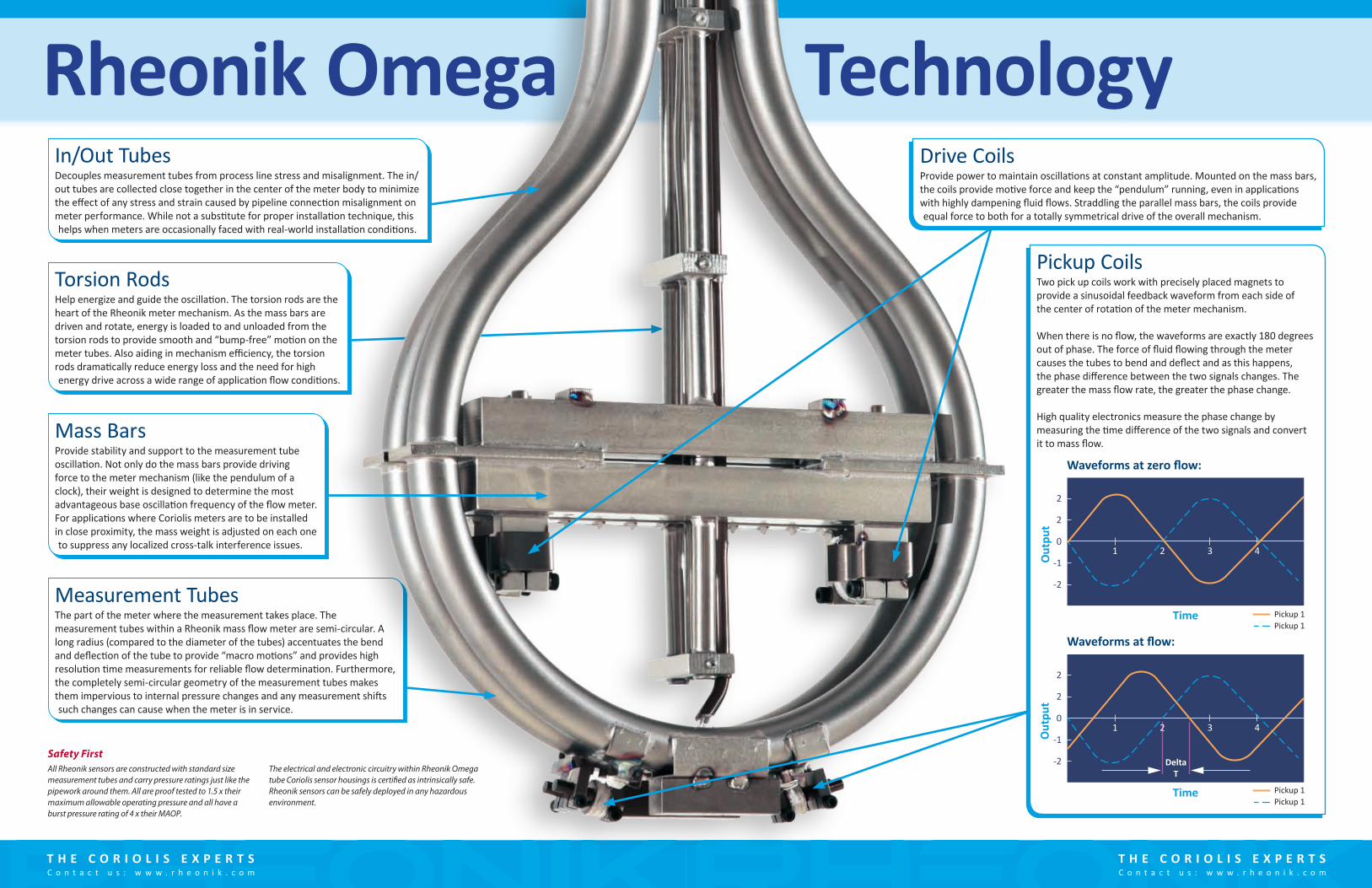
Drive CoilsProvide power to maintain oscillations at constant amplitude. Mounted on the mass bars, the coils provide motive force and keep the “pendulum” running, even in applications with highly dampening fluid flows. Straddling the parallel mass bars, the coils provide equal force to both for a totally symmetrical drive of the overall mechanism.
Measurement TubesThe part of the meter where the measurement takes place. The measurement tubes within a Rheonik mass flow meter are semi-circular. A long radius (compared to the diameter of the tubes) accentuates the bend and deflection of the tube to provide “macro motions” and provides high resolution time measurements for reliable flow determination. Furthermore, the completely semi-circular geometry of the measurement tubes makes them impervious to internal pressure changes and any measurement shifts such changes can cause when the meter is in service.
Torsion RodsHelp energize and guide the oscillation. The torsion rods are the heart of the Rheonik meter mechanism. As the mass bars are driven and rotate, energy is loaded to and unloaded from the torsion rods to provide smooth and “bump-free” motion on the meter tubes. Also aiding in mechanism efficiency, the torsion rods dramatically reduce energy loss and the need for high energy drive across a wide range of application flow conditions.
Rheonik Omega
Mass BarsProvide stability and support to the measurement tube oscillation. Not only do the mass bars provide driving force to the meter mechanism (like the pendulum of a clock), their weight is designed to determine the most advantageous base oscillation frequency of the flow meter. For applications where Coriolis meters are to be installed in close proximity, the mass weight is adjusted on each one to suppress any localized cross-talk interference issues.
In/Out TubesDecouples measurement tubes from process line stress and misalignment. The in/out tubes are collected close together in the center of the meter body to minimize the effect of any stress and strain caused by pipeline connection misalignment on meter performance. While not a substitute for proper installation technique, this helps when meters are occasionally faced with real-world installation conditions.
All Rheonik sensors are constructed with standard size measurement tubes and carry pressure ratings just like the pipework around them. All are proof tested to 1.5 x their maximum allowable operating pressure and all have a burst pressure rating of 4 x their MAOP.
The electrical and electronic circuitry within Rheonik Omega tube Coriolis sensor housings is certified as intrinsically safe. Rheonik sensors can be safely deployed in any hazardous environment.
Safety First
Technology
Pickup CoilsTwo pick up coils work with precisely placed magnets to provide a sinusoidal feedback waveform from each side of the center of rotation of the meter mechanism.
When there is no flow, the waveforms are exactly 180 degrees out of phase. The force of fluid flowing through the meter causes the tubes to bend and deflect and as this happens, the phase difference between the two signals changes. The greater the mass flow rate, the greater the phase change.
High quality electronics measure the phase change by measuring the time difference of the two signals and convert it to mass flow.
2
2
1 2 3 40
Out
put
Time
-1
-2
2
2
1 3 40
Out
put
Time
DeltaT
-1
-2
2
Pickup 1Pickup 1
Pickup 1Pickup 1
Waveforms at zero flow:
Waveforms at flow:

T H E C O R I O L I S E X P E R T SC o n t a c t u s : w w w . r h e o n i k . c o m
T H E C O R I O L I S E X P E R T SC o n t a c t u s : w w w . r h e o n i k . c o m
Meter Range Overview
Small sizes up to 50 kg/min (110 lbs/min)RHM015 to RHM08— ¼” to 1” line sizes— Small footprint – ideal for embedded systems and precise small flow applications
Mid range meters up to 1500 kg/min (3400 lbs/min)RHM12 to RHM40— 1” to 3” line sizes— Suited to industrial and process flow control and monitoring
Full Scale Meters up to 30000 kg/min (66140 lbs/min)RHM60 to RHM160— 4” to 12” line sizes— Perfect for material movements in small and wide scale operations
1000001000010001001010.10.010.001
RHM03RHM03
RHM04RHM04
RHM06RHM06
RHM08RHM08
RHM12RHM12
RHM15RHM15
RHM20RHM20
RHM30RHM30
RHM40RHM40
RHM60RHM60
RHM80RHM80
RHM100RHM100
RHM160RHM160
RHM015RHM015
Mass flow (kg/min)
Flow RangeThe Rheonik Omega tube Coriolis sensor range is carefully designed to provide complete coverage of mass flow rates from a few grams up to 30 tonnes per minute. Whatever the required flow range, Rheonik can cover it.
Flow rate chart depicts flow ranges for liquid applications at typical/common process pressure ratings. Flow ranges for meters with higher pressure ratings may vary. Gas flow ranges will depend upon pressure.
T H E C O R I O L I S E X P E R T SC o n t a c t u s : w w w . r h e o n i k . c o m
T H E C O R I O L I S E X P E R T SC o n t a c t u s : w w w . r h e o n i k . c o m
10
0.6
75:1
20:1
10:1
1:20
1:1
(Qm
ax)
50:1
(Qm
in)
0.5
0.4
0.3
0.2
0.1
0
-0.1
-0.2
-0.3
-0.4
-0.5
-0.6
20 30 40 50
Percentage of Qmax
Perc
enta
ge U
ncer
tain
ty(o
f mas
s flow
rate
)
60 70 80 90 100
P G B 1 C A
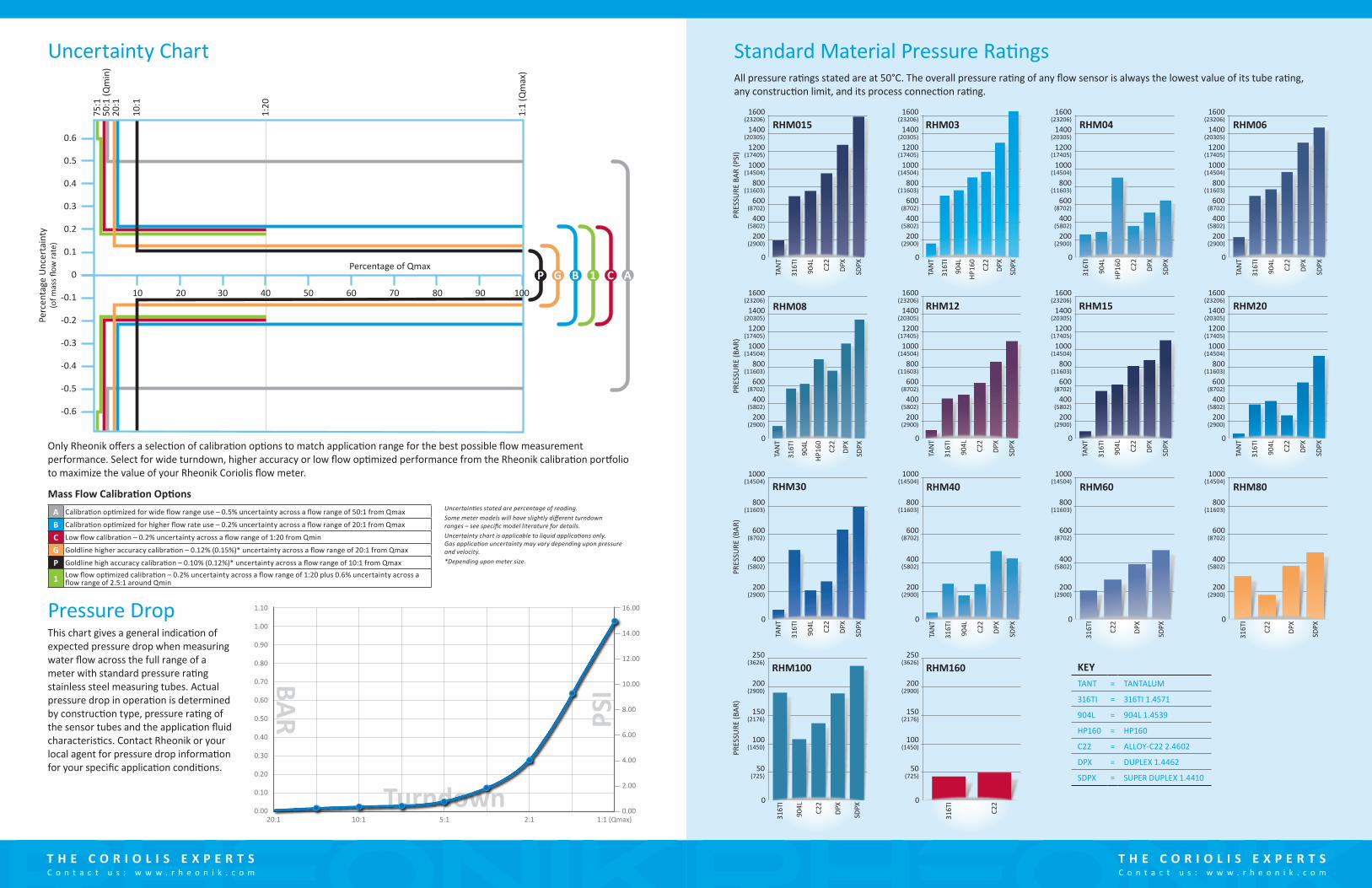
A Calibration optimized for wide flow range use – 0.5% uncertainty across a flow range of 50:1 from Qmax
B Calibration optimized for higher flow rate use – 0.2% uncertainty across a flow range of 20:1 from Qmax
C Low flow calibration – 0.2% uncertainty across a flow range of 1:20 from Qmin
G Goldline higher accuracy calibration – 0.12% (0.15%)* uncertainty across a flow range of 20:1 from Qmax
P Goldline high accuracy calibration – 0.10% (0.12%)* uncertainty across a flow range of 10:1 from Qmax
1 Low flow optimized calibration – 0.2% uncertainty across a flow range of 1:20 plus 0.6% uncertainty across a flow range of 2.5:1 around Qmin
Uncertainties stated are percentage of reading.Some meter models will have slightly different turndown ranges – see specific model literature for details.Uncertainty chart is applicable to liquid applications only. Gas application uncertainty may vary depending upon pressure and velocity.*Depending upon meter size.
Mass Flow Calibration Options
Uncertainty Chart
20:10.00
0.10
0.20
0.30
0.40
0.50
0.60
0.70
0.80
0.90
1.00
1.10 16.00
14.00
12.00
10.00
8.00
6.00
4.00
2.00
0.0010:1 5:1
Turndown
PSIBAR
2:1 1:1 (Qmax)
Pressure DropThis chart gives a general indication of expected pressure drop when measuring water flow across the full range of a meter with standard pressure rating stainless steel measuring tubes. Actual pressure drop in operation is determined by construction type, pressure rating of the sensor tubes and the application fluid characteristics. Contact Rheonik or your local agent for pressure drop information for your specific application conditions.
Only Rheonik offers a selection of calibration options to match application range for the best possible flow measurement performance. Select for wide turndown, higher accuracy or low flow optimized performance from the Rheonik calibration portfolio to maximize the value of your Rheonik Coriolis flow meter.
0
PRES
SURE
BAR
(PSI
)PR
ESSU
RE (B
AR)
PRES
SURE
(BAR
)PR
ESSU
RE (B
AR)
1600(23206)
200(2900)
400(5802)
600(8702)
800(11603)
1000(14504)
1200(17405)
1400(20305)
1600(23206)
200(2900)
400(5802)
600(8702)
800(11603)
1000(14504)
1200(17405)
1400(20305)
1600(23206)
200(2900)
400(5802)
600(8702)
800(11603)
1000(14504)
1200(17405)
1400(20305)
1600(23206)
200(2900)
400(5802)
600(8702)
800(11603)
1000(14504)
1200(17405)
1400(20305)
1600(23206)
200(2900)
400(5802)
600(8702)
800(11603)
1000(14504)
1200(17405)
1400(20305)
1600(23206)
200(2900)
400(5802)
600(8702)
800(11603)
1000(14504)
1200(17405)
1400(20305)
1600(23206)
200(2900)
400(5802)
600(8702)
800(11603)
1000(14504)
1200(17405)
1400(20305)
1600(23206)
200(2900)
400(5802)
600(8702)
800(11603)
1000(14504)
1200(17405)
1400(20305)
200(2900)
400(5802)
600(8702)
800(11603)
1000(14504)
200(2900)
400(5802)
600(8702)
800(11603)
1000(14504)
100(1450)
50(725)
150(2176)
200(2900)
250(3626)
100(1450)
50(725)
150(2176)
200(2900)
250(3626)
200(2900)
400(5802)
600(8702)
800(11603)
1000(14504)
200(2900)
400(5802)
600(8702)
800(11603)
1000(14504)
0 0 0
0 0 0 0
0 0 0 0
0 0
TAN
T
316T
I
904L
HP16
0
C22
DPX
SDPX
TAN
T
316T
I
904L
HP16
0
C22
DPX
SDPX
TAN
T
316T
I
904L C22
DPX
SDPX
TAN
T
316T
I
904L C22
DPX
SDPX
TAN
T
316T
I
904L C22
DPX
SDPX
TAN
T
316T
I
904L C22
DPX
SDPX
TAN
T
316T
I
904L C22
DPX
SDPX
316T
I
C22
DPX
SDPX
316T
I
C22
DPX
SDPX
HP16
0
316T
I
904L C22
DPX
SDPX
TAN
T
316T
I
904L C22
DPX
SDPX
316T
I
904L C22
DPX
SDPX
316T
I
C22
TAN
T
316T
I
904L C22
DPX
SDPX
RHM03 RHM06RHM015
RHM08 RHM15
RHM30
RHM12 RHM20
RHM80
RHM04
RHM40 RHM60
RHM100 RHM160
All pressure ratings stated are at 50°C. The overall pressure rating of any flow sensor is always the lowest value of its tube rating, any construction limit, and its process connection rating.
Standard Material Pressure Ratings
KEYTANT = TANTALUM
316TI = 316TI 1.4571
904L = 904L 1.4539
HP160 = HP160
C22 = ALLOY-C22 2.4602
DPX = DUPLEX 1.4462
SDPX = SUPER DUPLEX 1.4410
T H E C O R I O L I S E X P E R T SC o n t a c t u s : w w w . r h e o n i k . c o m
T H E C O R I O L I S E X P E R T SC o n t a c t u s : w w w . r h e o n i k . c o m
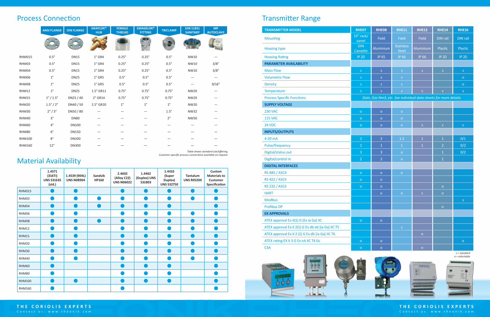
Process Connection
Material Availability
ANSI FLANGE DIN FLANGE GRAYLOK® HUB
FEMALE THREAD
SWAGELOK® FITTING TRICLAMP DIN 11851
SANITARYMP
AUTOCLAVE
RHM015 0.5" DN15 1" GR4 0.25" 0.25" 0.5" NW10 —
RHM03 0.5" DN15 1" GR4 0.25" 0.25" 0.5" NW10 3/8"
RHM04 0.5" DN15 1" GR4 0.25" 0.25" 0.5" NW10 3/8"
RHM06 1" DN25 1" GR5 0.5" 0.5" 0.5" — —
RHM08 1" DN25 1" GR5 0.5" 0.5" 0.5" — 9/16"
RHM12 1" DN25 1.5" GR11 0.75" 0.75" 0.75" NW20 —
RHM15 1" / 1.5" DN25 / 40 2" GR14 0.75" 0.75" 0.75" NW20 —
RHM20 1.5" / 2" DN40 / 50 2.5" GR20 1" 1" 1" NW20 —
RHM30 2" / 3" DN50 / 80 — — — 1.5" NW32 —
RHM40 3" DN80 — — — 2" NW50 —
RHM60 4" DN100 — — — — — —
RHM80 6" DN150 — — — — — —
RHM100 8" DN200 — — — — — —
RHM160 12" DN300 — — — — — —
1.4571 (316Ti)
UNS S31635 (std.)
1.4539 (904L) UNS N08904
Sandvik HP160
2.4602 (Alloy C22)
UNS N06022
1.4462 (Duplex) UNS
S31803
1.4410 (Super
Duplex) UNS S32750
Tantalum UNS R05200
Custom Materials to
Customer Specification
RHM015
RHM03
RHM04
RHM06
RHM08
RHM12
RHM15
RHM20
RHM30
RHM40
RHM60
RHM80
RHM100
RHM160
Table shows standard size/offering. Customer specific process connections available on request.
Transmitter RangeTRANSMITTER MODEL RHE07 RHE08 RHE11 RHE12 RHE14 RHE16
Mounting 19" rack/panel Field Field Field DIN rail DIN rail
Housing type DIN Cassette Aluminium Stainless
Steel Aluminium Plastic Plastic
Housing Rating IP 20 IP 65 IP 66 IP 66 IP 20 IP 20
PARAMETER AVAILABILITY
Mass Flow s s s s s s
Volumetric Flow s s s o
Density s s s o
Temperature s s s s s s
Process Specific Functions Gain, Gas Nm3, etc. See individual data sheets for more details.
SUPPLY VOLTAGE
230 VAC o o o
115 VAC o o o
24 VDC o o o s s s
INPUTS/OUTPUTS
4-20 mA 2 2 1-2 1 1 0/1
Pulse/frequency 1 1 1 1 2 0/2
Digital/status out 3 3 o 1 0/2
Digital/control in 2 2 o 1
DIGITAL INTERFACES
RS 485 / ASCII o o o
RS 422 / ASCII o o
RS 232 / ASCII o o o
HART o o s o
Modbus s
Profibus DP o
EX APPROVALS
ATEX approval Ex II(1) G [Ex ia Ga] IIC o o
ATEX approval Ex II 2(1) G Ex db eb [ia Ga] IIC T5 s
ATEX approval Ex II 2 (1) G Ex db [ia Ga] IIC T6 o
ATEX rating EX II 3 G Ex nA IIC T4 Gc o o o
CSA o o os = standard
o = selectable

Unlike many other flow meter manufacturers, Rheonik only make Coriolis meters – we are The Coriolis Experts – and your purchase of a Rheonik Mass Flow solution is supported globally by engineering professionals with many years of experience in metering and measurement instrumentation.
Rheonik has been manufacturing high quality, high specification Coriolis mass flow meters for over 30 years. Contact us today to discover more about Rheonik Coriolis technology and become one of the many satisfied users around the world who rely on Rheonik for critical flow measurement in their applications.
T H E C O R I O L I S E X P E R T SC o n t a c t u s : w w w . r h e o n i k . c o m
Your local agent: