Ramsey Winch Company OWNER’S MANUAL · Ramsey Winch Company OWNER’S MANUAL MODEL 800 / H-800...
36
1 CAUTION : READ AND UNDERSTAND THIS MANUAL BEFORE INSTALLATION AND OPERATION OF WINCH. SEE WARNINGS! Ramsey Winch Company OWNER’S MANUAL MODEL 800 / H-800 SERIES DOW-LOK® EQUIPPED INDUSTRIAL LOW-MOUNT WINCHES Rated Line Pull (lbs.) 20,000 (kg) 9,060 Gear Reduction 40:1 800 Y-800 H-800 HY-800 Shipping Weight: 315 lbs. (143 Kg) 290 lbs (132 Kg) 330 lbs. (150 Kg) 325 lbs. (148 Kg) Layer of Cable 1 2 3 4 5** (lbs.) 20,000 16,600 14,200 12,400 11,000 (kg) 9,060 7,510 6,430 5,610 4,980 *Cable Capacity (ft)* 35 75 125 180 240 800 / H-800 (m)* 10 22 38 54 72 *Cable Capacity (ft)* 20 45 75 110 150 Y-800 / HY-800 (m)* 6 13 22 33 45 *Line speed Worm RPM FPM 22 27 32 35 40 MPM 6.6 8.1 9.7 10.9 12.3 FPM 18 22 26 29 33 460 MPM 5.4 6.6 7.9 8.8 10.0 30 GPM ** Fifth layer does not conform to SAE J706 Note: The rated line pulls shown are for the winch only. Consult wire rope manufacturer for wire rope ratings *Rated line pull per layer 570 * These specifications are based on recommended wire rope of .63 inch (16mm) diameter 6x19 extra improved plow steel cable 800 H-800 Congratulations Ramsey Winches are designed and built to exacting specifications. Great care and skill go into every winch we make. If the need should arise, warranty procedure is outlined on the back of your self-addressed postage paid warranty card. Please read and fill out the enclosed warranty card and send it to Ramsey Winch Company. If you have any problems with your winch, please follow instructions for prompt service on all warranty claims. Refer to back page for limited warranty.
Transcript of Ramsey Winch Company OWNER’S MANUAL · Ramsey Winch Company OWNER’S MANUAL MODEL 800 / H-800...

1
CAUTION: READ AND UNDERSTAND THIS MANUAL BEFORE INSTALLATION AND OPERATION OF WINCH. SEE WARNINGS!
Ramsey Winch Company OWNER’S MANUAL
MODEL 800 / H-800 SERIES DOW-LOK® EQUIPPED
INDUSTRIAL LOW-MOUNT WINCHES
Rated Line Pull (lbs.) 20,000 (kg) 9,060Gear Reduction 40:1
800 Y-800 H-800 HY-800
Shipping Weight: 315 lbs. (143 Kg)
290 lbs (132 Kg)
330 lbs. (150 Kg)
325 lbs. (148 Kg)
Layer of Cable 1 2 3 4 5**(lbs.) 20,000 16,600 14,200 12,400 11,000(kg) 9,060 7,510 6,430 5,610 4,980
*Cable Capacity (ft)* 35 75 125 180 240 800 / H-800 (m)* 10 22 38 54 72*Cable Capacity (ft)* 20 45 75 110 150 Y-800 / HY-800 (m)* 6 13 22 33 45
*Line speedWorm RPM
FPM 22 27 32 35 40MPM 6.6 8.1 9.7 10.9 12.3FPM 18 22 26 29 33 460MPM 5.4 6.6 7.9 8.8 10.0 30 GPM
** Fifth layer does not conform to SAE J706
Note: The rated line pulls shown are for the winch only. Consult wire ropemanufacturer for wire rope ratings
*Rated line pull per layer
570
* These specifications are based on recommended wire rope of .63 inch (16mm) diameter 6x19 extra improved plow steel cable
800
H-800
Congratulations Ramsey Winches are designed and built to exacting specifications. Great care and skill go into every winch we make. If the need should arise, warranty procedure is outlined on the back of your self-addressed postage paid warranty card. Please read and fill out the enclosed warranty card and send it to Ramsey Winch Company. If you have any problems with your winch, please follow instructions for prompt service on all warranty claims. Refer to back page for limited warranty.

1
Performance Specifications ...............................COVER Safety Precautions......................................................1 Techniques of Operation ..........................................2-3 Winch Maintenance ....................................................3 Winch Mounting .........................................................4 Cable Installation ........................................................4 Adjusting the Oil Cooled Worm Brake ...............................................................4 Servicing the Oil Cooled Worm Brake ...............................................................5 Re-assembling and Checking the Brake.....................................................5 Test for Proper Brake Assembly ..................................6 Instructions for Checking Assembly Arrangement and Setting of Worm Brake ........................................6 Adjustment of Clutch Air Shifter ..................................7 Hydraulic System Requirements .................................8
Trouble Shooting Guide...............................................9 Instructions for Overhaul ..................................... 10-16 Disassembly....................................................... 10-13 Re-assembly ...................................................... 13-16 Dimensional Drawings Model 800 / Y-800................................................17 Model H-800 / HY-800..........................................18 H-800 / HY-800 Short Coupling.............................19 H-800 / HY-800 Air Shifter ....................................20 HY-800 Short Coupling/Low Profile Shifter ............21 Parts List and Parts Drawing Model 800 / Y-800.......................................... 22-23 Model H-800 / HY-800.................................... 24-25 H-800 / HY-800 SC......................................... 26-27 H-800 / HY-800 Air Shifter .............................. 38-29 Hy-800 Short Coupling/Low Profile Shifter....... 30-31 Warranty .................................................BACK COVER
Contents
Safety Precautions To Guard Against Possible Injury A. Clutch must be totally engaged before starting the winch operation.
B. Do not disengage clutch under load.
C. Stay out from under and away from raised loads.
D. Stand clear of cable while pulling. Do not try to guide cable.
E. Do not exceed maximum line pull ratings shown in specifications.
F. Do not use winch to lift, support, or otherwise transport people.
G. A minimum of 5 wraps of cable around the drum barrel is necessary to hold load. Cable set screw is not designed to hold load.

2
Techniques of Operation The best way to get acquainted with how your winch operates is to make test runs before you actually use it. Plan your test in advance. Remember, you hear your winch, as well as see it operate. Get to recognize the sounds of a light steady pull, a heavy pull, and sounds caused by load jerking or shifting. Gain confidence in operating your winch and its use will be-come second nature with you.
The uneven spooling of cable, while pulling a load, is not a problem, unless there is a cable pileup on one end of drum. If this happens reverse the winch to relieve the load and move your anchor point further to the center of the vehicle. After the job is done you can unspool and rewind for a neat lay of the cable.
The Dow-Lok® clutch provides free spooling and clutch engagement with the cable drum. With the clutch disengaged, the cable can be freespooled off the drum. For winching in the load the clutch must be fully engaged with the drum.
The Dow-Lok® clutch is latched into either the engaged, “IN” position, or the disengaged “OUT” position, by a pin at the bottom of the shifter handle which fits into latching slots.
TO UNLATCH CLUTCH
Run winch in the reverse (reel out) direction until the load is off the cable, Grasp handle firmly and while pushing on the top of the handle with the thumb for leverage, lift until pin clears latching slots.
TO ENGAGE CLUTCH
Unlatch and pull handle toward “IN” position as far as it will go. In order to attain full engagement, internal elements of the clutch must be aligned. This alignment will take place when the cable drum or cable drum shaft turns a maximum of 1/4 revolution. The clutch will automatically spring into engagement and pin will drop into “IN” slots when this alignment takes place. Do not attempt to lift a load unless pin is fully into “IN” slots. Keep clear of spring-loaded handle during automatic engagement.
TO DISENGAGE CLUTCH
Unlatch and push handle to “OUT” position and fully insert pin into latching slots. Do not disengage the clutch under load.
The Dow-Lok® air-shifter clutch provides free spooling and clutch engagement with the cable drum. With the clutch disengaged, the cable can be freespooled off the drum. For winching in the load the clutch must be fully engaged with the drum.
TO ENGAGE CLUTCH
There must be a minimum of 1 foot of slack in the cable before attempting to engage the clutch. This will allow the drum to rotate a minimum of 1/4 turn allowing engagement of the clutch before picking up the load. With this slack in the cable, exhaust air pressure from the air shift cylinder. Run the winch in the “IN” direction until the clutch starts to turn. Clutch must be fully engaged before starting the winch operation.
TO DISENGAGE CLUTCH
Run winch in the “OUT” direction until there is no load on the cable. Apply 70-90 psi to the air shift cylinder to dis-engage the clutch. Do not disengage the clutch under load.

3
The Dow-Lok® low-profile shifter clutch provides free spooling and clutch engagement with the cable drum. With the clutch disengaged, the cable can be freespooled off the drum. For winching in the load the clutch must be fully engaged with the drum.
TO ENGAGE CLUTCH
Raise the handle so the notch clears the bracket, and pull handle out as far as it will go. The clutch will automati-cally spring into engagement and latch when the clutch aligns with the drum shaft. In order to attain full engage-ment, internal elements of the clutch MUST be aligned. This alignment will take place when cable drum or cable drum shaft turns a maximum of 1/4 revolution. Do not attempt to lift a load unless notch in shifter shaft is se-curely latched. Keep clear of spring-loaded handle during automatic engagement.
TO DISENGAGE CLUTCH
Raise handle so notch clears bracket. Push handle in and latch the shaft notch onto bracket. Do not disengage the clutch under load.
WINCH MAINTENANCE Adhering to the following maintenance schedule will keep your winch in top condition and performing as it should with a minimum of repair.
A. WEEKLY 1. Check the oil level and maintain it to the oil level plug. If oil is leaking out, determine location and repair.
2. Check the pressure relief plug in top of the gear housing. Be sure that it is in good operating condition so that hot oil gasses may escape.
3. Lubricate cable with light oil.
B. MONTHLY 1. Lubricate the various grease fittings located in the ends of cable drum shaft, end bearing, clutch housing or clutch op-
erating linkage. Any good grade of grease containing moly-disulfide is acceptable.
2. In the case of jaw clutch winches, check the action of the sliding clutch, making sure it is fully engaging and disengag-ing with the cable drum. Observe the jaws on both the clutch and cable drum, checking for rounding of the driving faces. If rounding has occurred they should be replaced immediately.
3. In the case of Dow-Lok® clutches, check the action of the locking ring. Make sure it is spring loaded and free to move fully against the cable drum in the engaged position and that it is pulled fully away from the cable drum and latched when disengaged.
4. Check the winch mounting bolts. If any are missing, replace them and securely tighten any that are loose. Make sure to use only grade 5 bolts or better.
5. Check the torque setting of the oil cooled worm brake. Make any adjustments required, following the procedure de-scribed in ADJUSTING THE OIL COOLED WORM BRAKE in the Owner's Manual.
6. Check alignment of chain and sprockets and adjust as required to minimize wear.
7. Inspect the cable. If the cable has become frayed with broken strands, replace immediately.
C. ANNUALLY 1. Drain the oil from the winch annually or more often if winch is used frequently.
2. Fill the winch to the oil level plug with clean kerosene. Run the winch a few minutes with no load in the reel in direc-tion. Drain the kerosene from the winch.
3. Refill the winch to the oil level plug with all purpose E.P. 140 gear oil.
4. Inspect frame and surrounding structure for cracks or deformation.
5. Gear wear can be estimated by rocking the drum back and forth and if necessary drain oil and remove cover for closer inspection.
4
WINCH MOUNTING It is most important that this winch be mounted securely so that the three major sections (the clutch housing end, the cable drum and the gear-housing end) are properly aligned.
All standard H-800 Dow-Lok® series winches are furnished with recommended mounting angles. Angle size is 1/2 x 3 x 4 high strength steel angle.
CABLE INSTALLATION The Ramsey Model H-800 "Dow-Lok"® winch has two tapered pockets cast into the drum. One pocket is for installations with the wire rope wound over the drum. The other pocket is for an underwound wire rope.
1. Slide the wire rope through narrow end of the pocket against the drum flange.
2. Wrap the wire rope around the anchor "puck" and pull the wire rope and anchor back into the wide end of the pocket.
3. Use a soft hammer to drive the back side of the wire rope, firmly seating the wire rope and anchor, into the pocket.
The wire rope can easily be removed from the drum by driving the anchor out the wide end of the pocket.
The Ramsey Model Y-800/HY-800 ("Y" drum) "Dow-Lok"® winch has a setscrew to secure cable to drum.
Insert the end of cable, opposite hook end, into the 11/16" dia. hole in drum barrel. Secure cable to drum barrel, using set-screw furnished with winch. TIGHTEN SETSCREW SECURELY.
Carefully run the winch in the "reel-in" direction, keeping tension on end of cable, spool all the cable onto the cable drum, taking care to form neatly wrapped layers.
ADJUSTING THE OIL COOLED WORM BRAKE The oil cooled, fully adjustable, automatic worm brake operates in the worm housing lubricant, all parts being submerged in oil. When the brake wears to the point that the load begins to drift, the brake can be adjusted as follows:
1. Loosen the adjusting screw lock nut.
2. Tighten the brake by turning the adjusting screw clockwise. CAUTION: Only 1/4 turn is usually required to adjust the brake. Over-tightening can cause over-heating, and damage to the brake parts. Tighten the lock nut after adjustment is completed.
If the brake does not respond to adjustment then a new leaf spring and brake disc is needed.
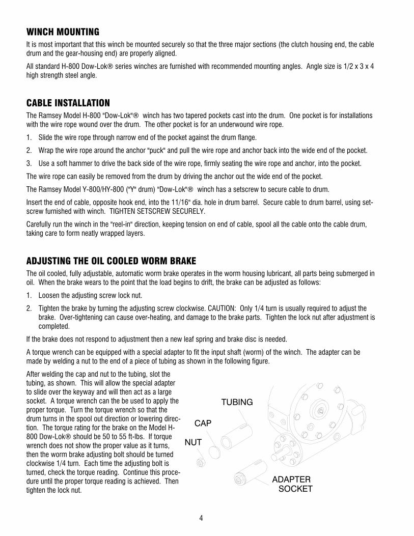
A torque wrench can be equipped with a special adapter to fit the input shaft (worm) of the winch. The adapter can be made by welding a nut to the end of a piece of tubing as shown in the following figure.
After welding the cap and nut to the tubing, slot the tubing, as shown. This will allow the special adapter to slide over the keyway and will then act as a large socket. A torque wrench can the be used to apply the proper torque. Turn the torque wrench so that the drum turns in the spool out direction or lowering direc-tion. The torque rating for the brake on the Model H-800 Dow-Lok® should be 50 to 55 ft-lbs. If torque wrench does not show the proper value as it turns, then the worm brake adjusting bolt should be turned clockwise 1/4 turn. Each time the adjusting bolt is turned, check the torque reading. Continue this proce-dure until the proper torque reading is achieved. Then tighten the lock nut.
ADAPTER
CAP
NUT
TUBING
SOCKET

5
SERVICING OF THE OIL COOLED SAFETY BRAKE 1. Remove the drain plug and drain the worm gear oil from the worm housing.
2. Back off the lock nut, then the adjusting screw, both two turns or more by turning them counter-clockwise.
3. Remove the cover mounting screws.
4. Remove the cover along with coil spring and leaf spring.
5. Remove the retainer plate, composition brake disc, cam plate and balls. Note which slots balls are in.
6. Inspect parts as follows:
a) Composition brake discs are 1/4" thick when new. Replace if thinner than 3/16 or if surfaces are glazed or burnt.
b) Inspect the flat, ground surface of the cam plate and retainer plate for glazing, warpage, or other damage. Glazing can be removed by scraping carefully.
c) Inspect the leaf spring. It should be bowed 1/8".
RE-ASSEMBLING AND CHECKING THE BRAKE 1. Press brake hub into place over worm shaft and key.
2. Assemble balls in appropriate slots of cam. Use stiff grease to hold balls into place and slide cam over end of worm. Be sure that balls are secure, between cam slots and hub slots. See instructions at right to determine proper ball slot setting. Install brake disc.
3. Install retainer plate, smooth side toward brake disc.
4. Install the gasket on the cover with a small amount of grease or sealer.
5. The coil spring goes over the adjusting screw on the inside of the cover.
6. Install the notches of the leaf spring on the pins protruding through the cover. The hollow side of the leaf spring goes toward the brake.
7. Install brake housing cover, making sure the protruding pins go through the leaf spring and into the holes in the retainer plate.
8. Bolt cover into place with the mounting screws. Install drain plug and add 3-3/4 pints all purpose E.P. 140 oil.
9. Turn winch in the hoisting direction at least one turn of the input shaft.
10. Turn the adjusting screw in until it is finger tight.
BALL
HUBA
BRAKE DISC
(LOOKING AT CAMPLATE FROM WINCH)
VIEW A-A
121
2
COMPOSITION
A
WORM BRAKE
LEAF SPRINGCOIL SPRING
BRAKE HOUSING
COVERMOUNTING
SCREW
ADJUSTINGSCREW
DIAGRAM 1
BRAKE COVER
THREAD SEAL
JAM NUT
RETAINER PLATE
CAM PLATE
GASKET
PIN

6
TEST FOR PROPER BRAKE ASSEMBLY After the brake has been adjusted to the proper torque setting disengage clutch. Start vehicle engine and run winch in the reel in (hoisting direction). Allow winch to run in this direction for one minute.
Place your hand on the safety brake housing. If housing is not hot to the touch then run winch in the reverse direction (cable out) for one minute. Brake housing should begin to heat.
When these conditions exist, proper installation has been made. If heating becomes noticeable when running the winch in forward rotation (hoisting direction), the brake should be again disassembled. When disassembled, place the brake balls in the alternate set of slots in the cam plates, then carefully follow the instructions for re-assembling and checking the brake.
INSTRUCTIONS FOR CHECKING ASSEMBLY ARRANGEMENT AND SETTING OF WORM BRAKE When the worm brake is assembled the brake must be set with the balls in the #1 or the #2 set of cam slots. (See View A-A, page 6). It is indicated on the name plate whether the balls were installed in the #1 or the #2 slots at the factory.
Three factors determine which slots the balls should be in:
1. Direction cable winds on the drum. It normally winds over the top of the drum barrel.
2. The cut of the gear set, right or left gear. The last letter in the model number of the winch, either R or L, designates right or left gear set. Example: R-20AR, R-30L, 700R, 800L.
3. The side of the winch that the input shaft is on. The Input Shaft is normally toward the cab. Whether the winch has a gear box on the right or the left side of the winch does not affect the brake setting.
When cable winds over the top of the drum, winch has a right cut gear and input shaft is toward the cab, then the balls need to be in the #2 cam slots.
If any one of these three factors differ from those stated above, the balls need to be in the #1 slots in the cam. A second change in these factors requires the original arrangement, and if all three factors are different, the balls need to be in the #1 slots.

7
ADJUSTMENT OF CLUTCH AIR SHIFTER 1. Place winch assembly back into mounting frame and
reattach using (8) mounting bolts and lockwashers. Torque mounting hardware to 290 ft. lbs. each. Make sure that gear housing and clutch housing are not rub-bing against drum flanges.
2. Place air shifter assembly #5 over shifter shaft aligning clevis over flats of shaft. Secure clevis to shaft using clevis pin #76 and cotter pin #75. Place shifter shaft in the "ENGAGED" position. With the air cylinder shaft fully retracted, push shifter assembly toward the drum until all play is taken out of the shifter shaft. Secure shifter assembly to clutch housing using (4) capscrews #46 (flanged hx. hd. serrated). Tighten securely, but do not torque.
3. Hook up air (70 to 90 psi) to inlet port of air cylinder and disengage clutch. Look into the opening in the clutch housing and verify that the locking ring and retainer plate are not making contact. Locking ring and retainer plate must not make contact. There must be a clearance (gap) of .09 inch (max.) between the locking ring and retainer plate when the winch is fully disengaged. If there is contact, the (4) capscrews #46 should be loos-ened and the plate pulled away from the drum approxi-mately .06 inch. Tighten screws securely and check action to assure needed clearance. Repeat adjustment procedure as needed to acquire needed gap. Shift clutch 2 or 3 times to verify proper shifting of clutch. After final adjustment, torque (4) capscrews #46 to 18 ft. lbs. each. Attach cover #43 using (4) capscrews #61.
76
1
53
PLATERETAINER LOCKING
RING
21
.09 MAX.
37
34
43
WINCH ASSEMBLY
39
61
61
8
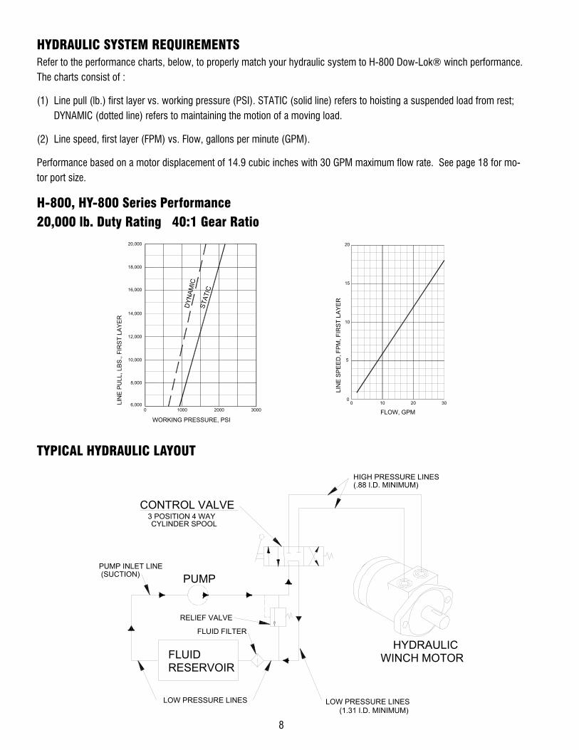
HYDRAULIC SYSTEM REQUIREMENTS Refer to the performance charts, below, to properly match your hydraulic system to H-800 Dow-Lok® winch performance. The charts consist of :
(1) Line pull (lb.) first layer vs. working pressure (PSI). STATIC (solid line) refers to hoisting a suspended load from rest; DYNAMIC (dotted line) refers to maintaining the motion of a moving load.
(2) Line speed, first layer (FPM) vs. Flow, gallons per minute (GPM).
Performance based on a motor displacement of 14.9 cubic inches with 30 GPM maximum flow rate. See page 18 for mo-tor port size.
H-800, HY-800 Series Performance 20,000 lb. Duty Rating 40:1 Gear Ratio
TYPICAL HYDRAULIC LAYOUT
LIN
E PU
LL, L
BS.
, FIR
ST
LAY
ER
WORKING PRESSURE, PSI
06,000
30001000 2000
LIN
E SP
EED
, FPM
, FIR
ST L
AYER
FLOW, GPM
5
00
10 20 30
16,000
8,000
18,000
10,000
20,000
12,000
14,000
STAT
IC
DYN
AMIC
10
15
20
PUMP INLET LINE
3 POSITION 4 WAY
PUMP
CYLINDER SPOOL
(1.31 I.D. MINIMUM)LOW PRESSURE LINES
HIGH PRESSURE LINES(.88 I.D. MINIMUM)
WINCH MOTORHYDRAULIC
LOW PRESSURE LINES
CONTROL VALVE
RESERVOIRFLUID
FLUID FILTER
RELIEF VALVE

9
TROUBLESHOOTING GUIDE
CONDITIONS POSSIBLE CAUSE CORRECTION
CLUTCH INOPERATIVE OR BINDS UP 1. Dry or rusted shaft. 1. Clean and Lubricate.
2. Bent yoke or linkage 2. Replace yoke or shaft assembly.
CLUTCH HANDLE WON’T LATCH 1. Debris in clutch. 1. Clean and lube per page 15.
OIL LEAKS FROM HOUSING 1. Seal damaged or worn. 1. Replace seal.
2. Too much oil. 2. Drain excess oil. Refer to Tech-
niques of Operation.
3. Damaged gasket. 3. Replace gasket.
LOAD DRIFTS DOWN 1. Worm brake has become worn. 1. Replace brake disc. (See page 6)
2. Worm brake out of adjustment. 2. Turn adjusting bolt clockwise 1/4
turn or until load does not drift.
WINCH RUNS TOO SLOW 1. Hydraulic motor worn out. 1. Replace motor.
2. Low flow rate. 2. Check flow rate. Refer to Hydraulic
Systems flow chart, page 8.
CABLE DRUM WILL NOT FREESPOOL 1. Winch not mounted squarely, caus-
ing end bearings to bind drum. 1. Check mounting. Refer to Winch
Mounting, page 5.
CABLE BIRDNESTS WHEN CLUTCH IS DISENGAGED
1. Drag brake disc worn. 1. Replace discs.
HYDRAULIC FLUID LEAKS FROM HOLE IN ADAPTER
1. Damaged motor shaft seal. 1. Replace seal.
10
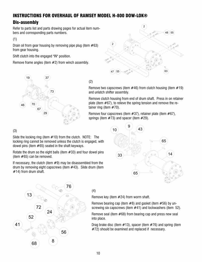
INSTRUCTIONS FOR OVERHAUL OF RAMSEY MODEL H-800 DOW-LOK® Dis-assembly Refer to parts list and parts drawing pages for actual item num-bers and corresponding parts numbers.
(1)
Drain oil from gear housing by removing pipe plug (item #63) from gear housing.
Shift clutch into the engaged "IN" position.
Remove frame angles (item #2) from winch assembly.
(2)
Remove two capscrews (item #46) from clutch housing (item #19) and unlatch shifter assembly.
Remove clutch housing from end of drum shaft. Press in on retainer plate (item #67), to relieve the spring tension and remove the re-tainer ring (item #70).
Remove four capscrews (item #37), retainer plate (item #67), springs (item #73) and spacer (item #29).
(3)
Slide the locking ring (item #10) from the clutch. NOTE: The locking ring cannot be removed unless the clutch is engaged, with dowel pins (item #65) seated in the shaft keyways.
Rotate the drum so the eight balls (item #33) and four dowel pins (item #65) can be removed.
If necessary, the clutch (item #9) may be disassembled from the drum by removing eight capscrews (item #43). Slide drum (item #14) from drum shaft.
(4)
Remove key (item #24) from worm shaft.
Remove bearing cap (item #8) and gasket (item #56) by un-screwing six capscrews (item #41) and lockwashers (item 52).
Remove seal (item #68) from bearing cap and press new seal into place.
Drag brake disc (item #13), spacer (item #76) and spring (item #72) should be examined and replaced if necessary.
48 55
47 55
2
2
63
19 37
73
4667
70
29
43
14
910
65
33
65
76
56
13
2472
68
5241
8

11
(5)
Remove motor (item #62) from adapter plate (item #26) by removing capscrews (item #51). Remove adapter plate and coupling (item #2) from adapter (item #3) by unscrewing eight capscrews (item #48).
Remove key (item #24) from worm shaft. Unscrew six cap-screws (item #50) and remove adapter from gear housing. Replace adapter seal (item #70) and gasket (item #57).
(5a)
Remove motor (item #59) from adapter (item #2) by removing two capscrews and lockwashers (item #48 & #52). Remove adapter (item #2) from gear housing by removing six (item #47) capscrews. Replace pilot seal (item #68) and gasket (item #54). Remove thrust bearing (item #32) and thrust washers (item #74).
(6)
Refer to page 5, SERVICING OIL COOLED SAFETY BRAKE. Re-move brake housing (item #18) from gear housing by unscrew-ing six (item #49) capscrews. Remove key (item #23) from worm. Remove worm (item #30) and bearings (item #34) from gear housing. Use a soft hammer to gently tap input end of worm and drive worm and bearing from gear housing. Once worm has been removed from housing, bearing can be pressed from end of worm.
Check for signs of wear or damage to worm (item #30) and bearings (item #34). Replace if necessary.
(7)
Remove gear housing cover (item #12) from gear housing (item #20) by unscrewing eight capscrews (item #40). Thread two of the capscrews into the two tapped holes of cover and tighten. This will pull the cover loose from gear housing.
Remove cover gasket (item #58) and pull shaft (item #27), with gear (item #17) and spacer (item #74) attached, from gear housing.
3
50
62
51
2
48
2670
24
3457
54
4847
59
68
74
2
28
32
34
49
18
3456
2330
4012
74
17
58
27
20

12
(8)
Check for signs of wear on gear teeth. If necessary, replace gear.
Check lube fittings (item #78) for damage and replace if nec-essary. Remove lube fittings (item #78) and reducers (item #62) from ends of shaft, if following Step 9, and reinstall after Step 9.
(9)
If shaft and/or gear hub is damaged, replace as follows:
a. Tap keys (item #25) into short keyways of drum shaft (item #27).
b. Press shaft (item #27) and keys through gear hub (item #17) until end of keys on long end of shaft are flush with hub.
(10)
Check gear housing bushing (item #5) and o-ring (item #63) for signs of wear. Replace if necessary by pressing old bushing from gear housing (item #20). Press new bushing into place and insert new o-ring (item #61) into groove inside of bushing.
(11)
Check drum bushings (items #35 & #36) for signs of wear. Replace if necessary by pressing old bushings from drum (item #14). Press bushing (item #35) into bore in drum until it's flange is seated against bottom of counter-bore. Press bushing (item #36) into opposite bore on drum until end of bushing extends .50" from end of drum.
62
62
78
78
27
541745
22
25
27
25
17
20 61
5
36
35
14
13
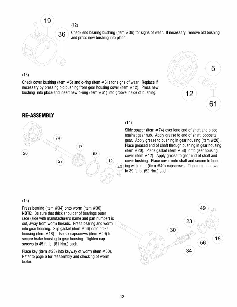
(12)
Check end bearing bushing (item #36) for signs of wear. If necessary, remove old bushing and press new bushing into place.
(13)
Check cover bushing (item #5) and o-ring (item #61) for signs of wear. Replace if necessary by pressing old bushing from gear housing cover (item #12). Press new bushing into place and insert new o-ring (item #61) into groove inside of bushing.
RE-ASSEMBLY (14)
Slide spacer (item #74) over long end of shaft and place against gear hub. Apply grease to end of shaft, opposite gear. Apply grease to bushing in gear housing (item #20). Place greased end of shaft through bushing in gear housing (item #20). Place gasket (item #58) onto gear housing cover (item #12). Apply grease to gear end of shaft and cover bushing. Place cover onto shaft and secure to hous-ing with eight (item #40) capscrews. Tighten capscrews to 39 ft. lb. (52 Nm.) each.
(15)
Press bearing (item #34) onto worm (item #30). NOTE: Be sure that thick shoulder of bearings outer race (side with manufacturer's name and part number) is out, away from worm threads. Press bearing and worm into gear housing. Slip gasket (item #56) onto brake housing (item #18). Use six capscrews (item #49) to secure brake housing to gear housing. Tighten cap-screws to 45 ft. lb. (61 Nm.) each.
Place key (item #23) into keyway of worm (item #30). Refer to page 6 for reassembly and checking of worm brake.
19
36
6112
5
74
20
27 12
58
17
40
5618
23
49
30
34

14
(16)
Press bearing (item #34) onto worm and into housing. NOTE: Be sure that thick shoulder of bearings outer race (side with manufacturer's name and part number) is out, away from worm threads. Attach bearing cap (item #8) to gear housing using six capscrews (item #41) with lockwashers (item #52). Tighten capscrews to 39 ft. lb. (52 Nm.) each. Insert key (item #24) into keyway of worm shaft.
(17)
Press bearing (item #34) onto worm and into housing. NOTE: Be sure that thick shoulder of bearings outer race (side with manufacturer's name and part number) is out, away from worm threads. Attach adapter (item #3) to gear housing using six capscrews (item #50). Tighten capscrews to 45 ft. lb. (61 Nm.) each. Insert key (item #24) into keyway of worm shaft. Slide coupling (item #2) over end of worm shaft. Attach adapter plate (item #26) to adapter using eight capscrews (item #48). Tighten capscrews to 21 ft. lb. (28 Nm.) each.
Place motor shaft, with key in keyway, into coupling. Secure motor (item #62) to adapter, using two capscrews (item #51). Tighten capscrews to 102 ft. lb. (138 Nm.) each.
(17a)
Place thrust washers (item #74) and thrust bearing (item #32) over end of worm (item #28) and into housing. Attach adapter (item #2) with gasket (item #54) to hous-ing, using six (item #47) capscrews. Tighten capscrews to 45 ft.lb. (61Nm.) each.
Insert pilot seal (item #68) into adapter and carefully place motor shaft, with key in keyway, through seal, so as not to damage seal. Insert motor shaft into end of worm (item #28). Secure motor (item #59) to coupling using two (item #48) capscrews with lockwashers (item #52). Tighten capscrews to 102 ft.lbs. (138 Nm.) each.
8
24
3456
5241
2
48
3
26
51
62
50
24
3457
59
4847
274
68
5432
28

15
(18)
Place winch with gear housing cover down on work bench. Drum shaft should be in vertical po-sition. Set springs (item #72) into pockets of gear housing with drag brakes (item #13) on top of disc (item #76) and springs. Slide drum assembly (item #14) onto drum shaft as shown.
(19)
Place clutch (item #9) over end of drum shaft. Align the clutch over the pilot bushing in drum. Install the eight cap-screws (item #43) and torque the cap-screws to 103 ft. lb. (139 Nm.) to securely seat the clutch to the drum.
Rotate the drum to align the clutch slots with the shaft keyways. Lightly grease four dowel pins (item #65) and eight balls (item #33). Use molybdenum disulfide or graphite bearing grease. In-sert the four dowel pins (item #65) and eight balls (item #33). In the engaged position the balls are nearly flush with the clutch.
Lightly grease the internal and external groove and bore in locking ring (item #10) and clutch (item #9).
Slide locking ring onto the clutch. When fully engaged, the locking ring touches the clutch flange and there is .71 to .73 inches between the end of the locking ring and the end of the clutch.
(20)
Place four springs (item #73) over four roll pins on retainer plate (item #67). Install spacer (item #29) and retainer plate and secure to clutch using four cap-screws (item #37). Tighten capscrews to 9.7 ft. lb. (13 Nm.) each. Firmly seat the retainer ring (item #70) into drum shaft groove.
Set the shifter assembly so that the screw heads en-gage the external groove in the locking ring (item #10). Push the clutch housing (item #19) onto the drum shaft and latch the shifter assembly in the engaged "IN" position. Insert the two capscrews (item #46).
43
14
910
65
33
65
13
72 76
14
11
37
73
70
2967
1946
39

16
(21)
Attach mounting angles (item #2) to winch assembly. Use capscrews (item #47 & #48) and lockwashers (item #55). Tighten capscrews to 290 ft. lb. (393 Nm) each. Insert plug (item #63) into hole in bottom of gear housing. Remove plugs (items #59 & 62) from top of housing. Pour 3 -3/4 pints of E.P. 140 oil into hole and replace plugs.
Check the action of the clutch by shifting and freespooling the winch drum several times.
The shift pattern plate on top of the clutch housing is adjusted at the factory to provide reliable shifting of the Dow-Lok® clutch. If the plate should loosen or be removed, you must readjust the plate. Shift the handle to disengage the clutch and hold against the internal stop. With the latching pin in the "OUT" slots, push the shift pattern plate toward the cable drum. Unsnap plastic lever cover from pattern plate. Tighten the four capscrews which hold the plate to housing. Snap lever cover back into place around the pattern plate.
6259
47 55
2
2
48 55
63

17
WIN
CH
MO
DE
L
800
Y-8
00
AB
CD
EF
10.6
226
9,7
196,
87.
7523
9,8
9.44
381,
015
.00
273,
010
.75
347,
413
.68
346,
213
.63
492,
219
.38
53,0
2.09
50,8
2.00
139,
75.
50
144,
55.
69
INC
HE
SM
MIN
CH
ESM
MIN
CH
ESM
MIN
CH
ES
MM
INC
HE
SM
MIN
CH
ESM
M
DIA
.
CLU
TCH
HO
US
ING
CA
N B
ER
OTA
TED
180
° FO
RC
US
TOM
ER IN
STA
LLAT
ION
DIM
EN
SIO
NS
SH
OW
N A
RE
INC
HES
OV
ER
MIL
LIM
ETE
RS
.31
x .1
5 x
2.0
LG.
KEY
WA
YDIA
.1.
2531
,7
A
B
1.25
31,7
7.75
196,
8
6.87
174,
6
F
Ø12
.13
308,
0
2.40
61,0
46.0
011
66,4
2.50
63,5
2.50
63,5
D
2.84
72,1
C10
.38
263,
68.
4321
4,3
1.87
47,5
.50
12,714
.00
355,
6
9.18
233,
16.
1815
6,9
3.50
88,9
E5.
1513
0,8
3.00
76,2
EN
GA
GE
DC
LUTC
HD
IS-E
NG
AG
ED
CLU
TCH
IN T
HIS
DIR
EC
TIO
NH
AN
DLE
SP
RIN
G L
OA
DE
D
Mod
el 8
00 D
ow-l
ok®
800
/ Y-8
00

18
WIN
CH
MO
DEL
H-8
00
HY
-800
AB
CD
EF
10.6
226
9,7
196,
87.
7523
9,8
9.44
381,
015
.00
350,
713
.81
347,
413
.68
346,
213
.63
492,
219
.38
1320
,852
.00
1168
,446
.00
139,
75.
50
144,
55.
69
INC
HES
MM
INC
HES
MM
INC
HES
MM
INC
HES
MM
INC
HE
SM
MIN
CH
ES
MM
DIM
ENSI
ON
S S
HO
WN
AR
E IN
CH
ES O
VER
MIL
LIM
ETE
RS
EN
GA
GE
DC
LUTC
HD
IS-E
NG
AG
EDC
LUTC
H
IN T
HIS
DIR
EC
TIO
NH
AN
DLE
SP
RIN
G L
OA
DE
D
1.25
31,7
7.75
196,
8
6.87
174,
6
F
Ø12
.13
308,
0
B
2.40
61,0
E
2.50
63,5
2.50
63,5
D
A2.
8472
,1
8.40
213,
3
C
5.15
130,
8
2.25
57,1
2.25
57,1
.50
12,7
3.00
76,2
14.0
035
5,6
9.18
233,
16.
1815
6,9
2.13
54,0
4.00
101,
6
10.3
826
3,6
.94
23,8
11.2
028
4,4
6.54
166,
1 8.36
212,
3
DIA
.
CLU
TCH
HO
US
ING
CA
N B
ER
OTA
TED
180
° FO
RC
US
TOM
ER
INST
ALL
ATI
ON
1-1/
16-2
0 O
-RIN
G P
OR
T2-
PLA
CE
S 1
80°
AP
AR
T
Mod
el 8
00 D
ow-l
ok®
H-8
00 /
HY-
800

19
CLU
TCH
HO
US
ING
CA
N B
ER
OTA
TED
180
° FO
RC
UST
OM
ER
INS
TALL
ATI
OND
IA.
HA
ND
LE S
PR
ING
LO
ADE
DIN
TH
IS D
IREC
TIO
N
CLU
TCH
DIS
-EN
GAG
EDC
LUTC
HEN
GAG
ED
DIM
ENSI
ON
S SH
OW
N A
RE
INC
HES
OVE
R M
ILLI
MET
ER
S
MM
INC
HES
MM
INC
HE
SM
MIN
CH
ES
MM
INC
HE
SM
MIN
CH
ESM
MIN
CH
ES
5.69
144,
5
5.50
139,
746
.00
1168
,4
52.0
013
20,8
19.3
849
2,2
13.6
334
6,2
13.6
834
7,4
13.8
135
0,7
15.0
038
1,0
9.44
239,
87.
7519
6,8
269,
710
.62
FE
DC
BA
HY
-800
H-8
00
MO
DEL
WIN
CH
1-1/
16-2
0 O
-RIN
G P
OR
T2-
PLA
CE
S 18
0° A
PAR
TC
2.84
72,1
A
D2.
5063
,52.
5063
,5
E
2.40
61,0
B
Ø12
.13
308,
0
F
6.87
174,
6
7.75
196,
8
1.25
31,7
10.3
826
3,6
6.18
156,
99.
1823
3,1
14.0
035
5,6
3.00
76,2
5.15
130,
8
6.41
162,
86.
5416
6,1
.94
23,8
.50
12,7
2.13
54,0
4.00
101,
6
8.36
212,
3
2.25
57,1
2.25
57,1
Mod
el 8
00 D
ow-l
ok®
H-8
00 /
HY-
800
SHOR
T CO
UPLI
NG

20
MM
INC
HES
MM
INC
HES
MM
INC
HES
MM
INC
HES
MM
INC
HES
MM
INC
HES
5.69
144,
5
5.50
139,
746
.00
1168
,4
52.0
013
20,8
19.3
849
2,2
13.6
334
6,2
13.6
834
7,4
13.8
135
0,7
15.0
038
1,0
9.44
239,
87.
7519
6,8
269,
710
.62
FE
DC
BA
HY-
800
H-8
00
MO
DE
LW
INC
H
8.36
212,
3
6.54
166,
111
.20
284,
4
.94
23,8
1-1/
16-2
0 O
-RIN
G P
OR
T2-
PLAC
ES 1
80°
APA
RT
10.3
826
3,6
4.00
101,
6
2.13
54,0
6.18
156,
99.
1823
3,1
8.91
226,
0
3.00
76,2
.50
12,7
2.25
57,1
2.25
57,1
5.15
130,
8
C
8.40
213,
3
2.84
72,1
A
DIA
.
D2.
5063
,52.
5063
,5
E
2.40
61,0
B
Ø12
.13
308,
0
F
6.87
174,
6
7.75
196,
8
1.25
31,7
DIM
ENSI
ON
S SH
OW
N A
RE
INC
HES
OVE
R M
ILLI
MET
ERS
1/8-
27N
PT P
OR
T(7
0 P
SI M
IN. P
RES
SUR
E)(9
0 PS
I MAX
. PR
ESSU
RE)
FOR
DIS
EN
GA
GIN
G C
LUTC
HC
LUTC
H IS
SPR
ING
EN
GAG
ED
3.13
79,3
Mod
el 8
00 D
ow-l
ok®
H-8
00 /
HY-
800
AIR
SHIF
TER

21
DIM
ENSI
ON
S SH
OW
N A
RE
INC
HES
OVE
R M
ILLI
MET
ERS
1-1/
16-2
0 O
-RIN
G P
OR
T2-
PLA
CE
S 18
0° A
PAR
T
EN
GA
GED
DIS
EN
GAG
ED
1.25
31,7
7.75
196,
8
6.87
174,
6
Ø5.5
013
9,7
Ø12.
1330
8,0
2.40
61,0
2.50
63,5
2.50
63,5
2.84
72,1
10.3
826
3,6
9.18
233,
26.
1815
6,9
3.50
88,9
5.15
130,
8
3.00
76,2
1.82
46,2
2.25
57,1
2.25
57,1
.94
23,8
6.54
166,
1 8.36
212,
3
8.13
206,
5
7.81
198,
4
9.41
239,
0
10.6
527
0,5
12.9
332
8,4
23.5
859
8,9
13.8
235
1,0
46.0
011
68,4
6.47
164,
3
8.13
206,
5
.50
12,7
Mod
el 8
00 D
ow-l
ok®
H-8
00 /
HY-
800
SHOR
T CO
UPLI
NG L
OW-P
ROFI
LE S
HIF
TER

22

23
Item
No.
Qty.
Part
s No
.De
scri
ptio
nIt
em N
o.Qt
y.Pa
rts
No.
Desc
ript
ion
11
2760
33SH
IFTE
R AS
SEM
BLY
408
4142
77CA
PSCR
EW 3
/8-1
6NC
X 1
LG H
X HD
GR5
NYL
OK H
VY P
22
3020
93AN
GLE
- Y80
041
641
4282
CAPS
CREW
3/8
-16N
C X
1-1/
4 LG
HX
HD D
R53
230
2111
ANGL
E - S
TD.
422
4143
99CA
PSCR
EW 3
/8-2
4NF
X 1-
1/4
LG A
LL-T
HRD
GR5
41
3060
35SP
RING
- FL
AT43
841
4571
CAPS
CREW
1/2
-20N
F X
1 LG
HX
HD G
R55
230
8083
BUSH
ING
441
4146
03CA
PSCR
EW 1
/2-2
0NF
X 1-
3/4
LG A
LL-T
HRD
GR5
61
3140
07CA
M P
LATE
71
3140
10CA
BLE
ANCH
OR ("
STD.
" DRU
M O
NLY
462
4146
19CA
PSCR
EW 1
/2-1
3NC
X 2-
1/2
LG H
X HD
ALL
-THR
D ZP
81
3160
06CA
P BE
ARIN
G47
441
4751
CAPS
CREW
3/4
-10N
C X
1-3/
4 GR
5 NY
LOK
HVY
PATC
H9
132
4151
CLUT
CH48
441
4777
CAPS
CREW
3/4
-10N
C X
1-3/
4 GR
510
132
4318
LOCK
ING
RING
496
4148
97CA
PSCR
EW 3
/8-1
6NC
X 1
LG S
OC H
D11
132
8027
COVE
R - B
RAKE
501
4180
67NU
T 1/
2-20
NF H
X JA
M12
132
8122
COVE
R - G
EAR
HOUS
ING
514
4181
63LO
CKW
ASHE
R 5/
16 M
ED S
ECT
PLTD
132
3300
10SH
OE -
DRAG
BRA
KE52
641
8177
LOCK
WAS
HER
3/8
MED
SEC
T PL
TD14
133
2167
DRUM
(STA
NDAR
D)53
441
8184
WAS
HER
- FLA
T 3/
8 AL
UM15
133
2172
DRUM
("Y"
800
)16
133
4189
GEAR
- L.
H.55
841
8249
LOCK
WAS
HER
3/4
MED
SEC
T17
133
4188
GEAR
- R.
H.56
244
2192
GASK
ET18
133
8221
HOUS
ING
- BRA
KE57
144
2194
GASK
ET19
133
8235
HOUS
ING
- CLU
TCH
581
4421
95GA
SKET
201
3382
42HO
USIN
G - G
EAR
591
4560
08FI
TTIN
G - R
ELIE
F21
134
0011
HUB
- BRA
KE60
145
6031
FITT
ING
- LUB
E61
246
2013
QUAD
-RIN
G23
134
2053
KEY
623
4680
02RE
DUCE
R24
134
2092
KEY
632
4680
11PI
PE P
LUG
252
3421
53KE
Y64
447
0042
PIN
- ROL
L26
135
2021
PLAT
E - R
ETAI
NER
654
4700
44PI
N - D
OWEL
271
3574
98SH
AFT
- DRU
M (S
TD.)
664
4700
56PI
N - R
OLL
281
3575
02SH
AFT
- DRU
M (Y
800)
671
4740
30PL
ATE
- RET
AINE
R29
136
2224
SPAC
ER68
148
6068
SEAL
- OI
L30
136
8082
WOR
M R
.H.
691
4860
76TH
READ
SEA
L31
136
8084
WOR
M L
.H.
701
4900
25RI
NG -
RETA
INER
322
4000
07BA
LL -
BRAK
E71
149
4010
SPRI
NG33
840
0011
BALL
- CL
UTCH
722
4940
22SP
RING
- DI
SC34
240
2045
BEAR
ING
- BAL
L73
449
4069
SPRI
NG35
141
2051
BUSH
ING
741
5180
16TH
RUST
WAS
HER
362
4120
52BU
SHIN
G75
153
0007
DISC
- BR
AKE
374
4140
38CA
PSCR
EW 1
/4-2
0NC
X 3/
4 LG
HX
HD G
R576
253
0094
SPAC
ER -
BRAK
E38
441
4069
CAPS
CREW
5/1
6-18
NC X
3/4
LG
HX H
D77
141
6059
SETS
CREW
("Y"
DRU
M O
NLY)
394
4141
11CA
PSCR
EW 5
/15-
18NC
X 1
LG
HX H
D GR
578
245
6039
LUBE
FIT
TING
PART
S LI
ST M
ODEL
800
DOW
-LO
K®

24

25
Item
No.
Qty.
Part
s No
.De
scri
ptio
nIt
em N
o.Qt
y.Pa
rts
No.
Desc
ript
ion
11
2760
33SH
IFTE
R AS
SEM
BLY
408
4142
77CA
PSCR
EW 3
/8-1
6NC
X 1
LG H
X HD
GR5
NYL
OK H
VY P
21
2997
33CO
UPLI
NG A
SSEM
BLY
412
4143
99CA
PSCR
EW 3
/8-2
4NF
X 1-
1/4
LG A
LL-T
HRD
GR5
31
3000
48AD
APTE
R42
841
4571
CAPS
CREW
1/2
-20N
F X
1 LG
HX
HD G
R54
230
2710
ANGL
E - Y
800
431
4146
03CA
PSCR
EW 1
/2-2
0NF
X 1-
3/4
LG A
LL-T
HRD
GR5
52
3027
11AN
GLE
- STD
.6
130
6035
SPRI
NG -
FLAT
452
4146
19CA
PSCR
EW 1
/2-1
3NC
X 2-
1/2
LG H
X HD
ALL
-THR
D ZP
72
3080
83BU
SHIN
G46
441
4751
CAPS
CREW
3/4
-10N
C X
1-3/
4 GR
5 NY
LOK
HVY
PATC
H8
131
4007
CAM
PLA
TE47
441
4777
CAPS
CREW
3/4
-10N
C X
1-3/
4 GR
59
131
4010
CABL
E AN
CHOR
("ST
D." D
RUM
ONL
Y)48
841
4871
CAPS
CREW
5/1
6-18
NC X
1-1
/4 L
G SO
C HD
LOK
-WEL
101
3241
51CL
UTCH
496
4148
97CA
PSCR
EW 3
/8-1
6NC
X 1
LG S
OC H
D11
132
4318
LOCK
ING
RING
506
4149
09CA
PSCR
EW 3
/8-1
6NC
X 1-
3/4
LG S
OC H
D LO
K-W
EL12
132
8027
COVE
R - B
RAKE
512
4149
50CA
PSCR
EW 1
/2-1
3NC
X 1-
3/4
LG S
OC H
D LO
K-W
EL13
132
8122
COVE
R - G
EAR
HOUS
ING
521
4180
67NU
T 1/
2-20
NF H
X JA
M14
233
0010
SHOE
- DR
AG B
RAKE
534
4181
63LO
CKW
ASHE
R 5/
16 M
ED S
ECT
PLTD
151
3321
67DR
UM (S
TAND
ARD)
544
4181
84W
ASHE
R - F
LAT
3/8
ALUM
161
3321
72DR
UM ("
Y" 8
00)
568
4182
49LO
CKW
ASHE
R 3/
4 M
ED S
ECT
171
3341
88GE
AR -
R.H.
572
4421
92GA
SKET
181
3382
21HO
USIN
G - B
RAKE
581
4421
94GA
SKET
191
3382
35HO
USIN
G - C
LUTC
H59
144
2195
GASK
ET20
133
8242
HOUS
ING
- GEA
R60
145
6008
FITT
ING
- REL
IEF
211
3400
11HU
B - B
RAKE
611
4560
31FI
TTIN
G - L
UBE
621
4580
48M
OTOR
- HY
D23
134
2053
KEY
632
4620
13QU
AD-R
ING
241
3420
92KE
Y64
346
8002
REDU
CER
252
3421
53KE
Y65
246
8011
PIPE
PLU
G26
135
0535
PLAT
E - H
YD. A
DAPT
ER66
447
0042
PIN
- ROL
L27
135
2021
PLAT
E - R
ETAI
NER
674
4700
44PI
N - D
OWEL
281
3574
98SH
AFT
- DRU
M (S
TD.)
684
4700
56PI
N - R
OLL
291
3575
02SH
AFT
- DRU
M (Y
800)
691
4740
30PL
ATE
- RET
AINE
R30
136
2224
SPAC
ER70
148
6068
SEAL
- OI
L31
136
8082
WOR
M R
.H.
711
4860
76TH
READ
SEA
L32
240
0007
BALL
- BR
AKE
721
4900
25RI
NG -
RETA
INER
338
4000
11BA
LL -
CLUT
CH73
149
4010
SPRI
NG34
240
2045
BEAR
ING
- BAL
L74
249
4022
SPRI
NG -
DISC
351
4120
51BU
SHIN
G75
449
4069
SPRI
NG36
241
2052
BUSH
ING
761
5180
16TH
RUST
WAS
HER
374
4140
38CA
PSCR
EW 1
/4-2
0NC
X 3/
4 LG
HX
HD G
R577
153
0007
DISC
- BR
AKE
384
4140
69CA
PSCR
EW 5
/16-
18NC
X 3
/4 L
G HX
HD
782
5300
94SP
ACER
- BR
AKE
394
4141
11CA
PSCR
EW 5
/16-
18NC
X 1
LG
HX H
D GR
579
141
6059
SETS
CREW
("Y"
DRU
M O
NLY)
802
4560
39LU
BE F
ITTI
NG
PART
S LI
ST M
ODEL
H-8
00 D
OW-L
OK®

26

27
Item
No.
Qty.
Part
No.
Desc
ript
ion
Item
No.
Qty.
Part
No.
Desc
ript
ion
11
2760
33SH
IFTE
R AS
SEM
BLY
408
4145
71CA
PSCR
EW 1
/2-2
0NF
X 1
LG H
X HD
GR5
21
3000
63AD
APTE
R41
141
4603
CAPS
CREW
1/2
-20N
F X
1-3/
4 LG
ALL
-THR
D GR
53
230
2710
ANGL
E - Y
800
42
3027
11AN
GLE
- STD
.43
241
4619
CAPS
CREW
1/2
-13N
C X
2-1/
2 LG
HX
HD A
LL-T
HRD
ZP5
130
6035
SPRI
NG -
FLAT
444
4147
51CA
PSCR
EW 3
/4-1
0NC
X 1-
3/4
GR5
NYLO
K HV
Y PA
TCH
62
3080
83BU
SHIN
G45
441
4777
CAPS
CREW
3/4
-10N
C X
1-3/
4 GR
57
131
4007
CAM
PLA
TE46
641
4897
CAPS
CREW
3/8
-16N
C X
1 LG
SOC
HD
81
3140
10CA
BLE
ANCH
OR (S
TD. D
RUM
ONL
Y)47
641
4913
CAPS
CREW
3/8
-16N
C X
1-1/
4 LG
SOC
HD
LOK-
WEL
91
3241
51CL
UTCH
482
4149
52CA
PSCR
EW 1
/2-1
3NC
X 1-
1/2
LG S
OC H
D LO
K-W
EL10
132
4318
LOCK
ING
RING
491
4180
67NU
T 1/
2-20
NF H
X JA
M11
132
8027
COVE
R - B
RAKE
504
4181
63LO
CKW
ASHE
R 5/
16 M
ED S
ECT
PLTD
121
3281
22CO
VER
- GEA
R HO
USIN
G51
441
8184
WAS
HER
- FLA
T 3/
8 AL
UM13
233
0010
SHOE
- DR
AG B
RAKE
141
3321
67DR
UM (S
TAND
ARD)
538
4182
49LO
CKW
ASHE
R 3/
4 M
ED S
ECT
151
3321
72DR
UM ("
Y" 8
00)
542
4421
92GA
SKET
161
3341
88GE
AR -
R.H.
551
4421
94GA
SKET
171
3382
21HO
USIN
G - B
RAKE
561
4421
95GA
SKET
181
3382
35HO
USIN
G - C
LUTC
H57
145
6008
FITT
ING
- REL
IEF
191
3382
42HO
USIN
G - G
EAR
581
4560
31FI
TTIN
G - L
UBE
201
3400
11HU
B - B
RAKE
591
4580
48M
OTOR
- HY
D60
246
2013
QUAD
-RIN
G22
134
2053
KEY
613
4680
02RE
DUCE
R23
234
2153
KEY
622
4680
11PI
PE P
LUG
241
3520
21PL
ATE
- RET
AINE
R63
447
0042
PIN
- ROL
L25
135
7498
SHAF
T - D
RUM
(STD
.)64
447
0044
PIN
- DOW
EL26
135
7502
SHAF
T - D
RUM
(Y80
0)65
447
0056
PIN
- ROL
L27
136
2224
SPAC
ER66
147
4030
PLAT
E - R
ETAI
NER
281
3681
96W
ORM
R.H
.67
148
6076
THRE
AD S
EAL
292
4000
07BA
LL -
BRAK
E68
148
6079
SEAL
- PI
LOT
308
4000
11BA
LL -
CLUT
CH69
149
0025
RING
- RE
TAIN
ER31
140
2045
BEAR
ING
- BAL
L70
249
4010
SPRI
NG32
140
2109
BEAR
ING
- THR
UST
712
4940
22SP
RING
- DI
SC33
141
2051
BUSH
ING
724
4940
69SP
RING
342
4120
52BU
SHIN
G73
151
8016
THRU
ST W
ASHE
R35
441
4038
CAPS
CREW
1/4
-20N
C X
3/4
LG H
X HD
GR5
742
5180
36TH
RUST
WAS
HER
364
4140
69CA
PSCR
EW 5
/16-
18NC
X 3
/4 L
G HX
HD
751
5300
07DI
SC -
BRAK
E37
441
4111
CAPS
CREW
5/1
6-18
NC X
1 L
G HX
HD
GR5
762
5300
94SP
ACER
- BR
AKE
388
4142
77CA
PSCR
EW 3
/8-1
6NC
X 1
LG H
X HD
GR5
N H
VY P
771
4160
59SE
TSCR
EW ("
Y" D
RUM
ONL
Y)39
241
4571
CAPS
CREW
3/8
-24N
F X
1-1/
4 LG
ALL
-THR
D GR
578
245
6039
LUBE
FIT
TING
PART
S LI
ST M
ODE
L H
-800
SC D
OW-L
OK®
(sho
rt c
oupl
ing)
28
45
37
4660
6460
79
29
1032
35
434
8
9
80
3
33
30
4560
5941
8131 17
6488
84
6748
21
33
1314
13
8884
22
71
4924
50
2
47
86
5825565
87
11
7419
6
76
72
23
26
23
43
12
6615
72
6
40
73
70
56
8338
207
76
36
28
61
62
48 8578
16
7542
4660
4
71
80
8235
69
63
57
55
27
53
39
68
4418
177
52 54
70
73
51

29
Item
No.
Qty.
Part
No.
Desc
ript
ion
Item
No.
Qty.
Part
No.
Desc
ript
ion
11
2996
95AI
R SH
IFTE
R BR
ACKE
T AS
SEM
BLY
431
4146
03CA
PSCR
EW 1
/2-2
0NF
X 1-
3/4
LG A
LL-T
HRD
GR5
21
2997
33CO
UPLI
NG A
SSEM
BLY
442
4146
19CA
PSCR
EW 1
/2-1
3NC
X 2-
1/2
LG H
X HD
ALL
-THR
D ZP
31
3000
48AD
APTE
R45
441
4751
CAPS
CREW
3/4
-10N
C X
1-3/
4 GR
5 NY
LOK
HVY
PATC
H4
230
2710
ANGL
E - "
Y" D
RUM
464
4147
77CA
PSCR
EW 3
/4-1
0NC
X 1-
3/4
GR5
230
2711
ANGL
E - S
TD.
478
4148
71CA
PSCR
EW 5
/16-
18NC
X 1
-1/4
LG
SOC
HD L
OK-W
EL5
130
6035
SPRI
NG -
FLAT
488
4148
97CA
PSCR
EW 3
/8-1
6NC
X 1
LG S
OC H
D6
230
8083
BUSH
ING
496
4149
09CA
PSCR
EW 3
/8-1
6NC
X 1-
3/4
LG S
OC H
D LO
K-W
EL7
131
4007
CAM
PLA
TE50
241
4950
CAPS
CREW
1/2
-13N
C X
1-3/
4 LG
SOC
HD
LOK-
WEL
81
3140
10CA
BLE
ANCH
OR ("
STD.
" DRU
M O
NLY)
511
4160
61SE
TSCR
EW 3
/8-2
4NF
X 1-
1/4
LG1
4160
59SE
TSCR
EW ("
Y" D
RUM
ONL
Y)52
441
6214
SCRE
W #
10-3
2NF
X 1/
4 LG
RD
HD Z
/P9
132
4151
CLUT
CH53
441
6262
SCRE
W #
10-3
2NF
X 3/
4 LG
HX
SOC
Z/P
101
3243
18LO
CKIN
G RI
NG54
241
8035
NUT
3/8-
16NC
HX
REG
Z/P
111
3280
27CO
VER
- BRA
KE55
141
8041
NUT
3/8-
24NF
HX
JAM
121
3281
22CO
VER
- GEA
R HO
USIN
G56
141
8067
NUT
1/2-
20NF
HX
JAM
132
3300
10SH
OE -
DRAG
BRA
KE57
441
8141
LOCK
WAS
HER
#10
MED
SEC
T Z/
P14
133
2167
DRUM
(STA
NDAR
D)58
441
8163
LOCK
WAS
HER
5/16
MED
SEC
T PL
TD1
3321
72DR
UM ("
Y")
594
4181
84W
ASHE
R - F
LAT
3/8
ALUM
151
3341
88GE
AR -
R.H.
608
4182
49LO
CKW
ASHE
R 3/
4 M
ED S
ECT
161
3700
47YO
KE61
142
4005
COTT
ER P
IN17
133
8221
HOUS
ING
- BRA
KE62
142
4029
CLEV
IS P
IN18
133
8235
HOUS
ING
- CLU
TCH
631
4330
16AI
R CY
LIND
ER19
133
8242
HOUS
ING
- GEA
R64
244
2192
GASK
ET20
134
0011
HUB
- BRA
KE65
144
2194
GASK
ET21
134
2053
KEY
661
4421
95GA
SKET
221
3420
92KE
Y67
145
6008
FITT
ING
- REL
IEF
232
3421
53KE
Y68
145
6031
FITT
ING
- LUB
E24
135
0535
PLAT
E - H
YD. A
DAPT
ER69
145
6038
BREA
THER
VEN
T25
135
2021
PLAT
E - R
ETAI
NER
702
4560
39LU
BE F
ITTI
NG26
135
7498
SHAF
T - D
RUM
(STD
.)71
145
8048
MOT
OR -
HYD
135
7502
SHAF
T - D
RUM
("Y"
)72
246
2013
QUAD
-RIN
G27
135
8067
CLEV
IS73
346
8002
REDU
CER
281
3580
69SH
IFTE
R SH
AFT
742
4680
11PI
PE P
LUG
291
3622
24SP
ACER
754
4700
42PI
N - R
OLL
301
3680
82W
ORM
R.H
.76
447
0044
PIN
- DOW
EL31
240
0007
BALL
- BR
AKE
771
4700
45PI
N - R
OLL
328
4000
11BA
LL -
CLUT
CH78
447
0056
PIN
- ROL
L33
240
2045
BEAR
ING
- BAL
L79
147
4030
PLAT
E - R
ETAI
NER
341
4120
51BU
SHIN
G80
148
6068
SEAL
- OI
L35
241
2052
BUSH
ING
811
4860
76TH
READ
SEA
L36
141
3074
COVE
R - A
IR S
HIFT
821
4900
25RI
NG -
RETA
INER
374
4140
38CA
PSCR
EW 1
/4-2
0NC
X 3/
4 LG
HX
HD G
R583
149
4010
SPRI
NG38
441
4111
CAPS
CREW
5/1
6-18
NC X
1 L
G HX
HD
GR5
842
4940
22SP
RING
- DI
SC39
441
4126
CAPS
CREW
5/1
6-18
NC X
3/4
LG
HX H
D85
449
4069
SPRI
NG40
841
4277
CAPS
CREW
3/8
-16N
C X
1 LG
HX
HD G
R5 N
YLOK
HVY
P86
151
8016
THRU
ST W
ASHE
R41
241
4399
CAPS
CREW
3/8
-24N
F X
1-1/
4 LG
ALL
-THR
D GR
587
153
0007
DISC
- BR
AKE
428
4145
71CA
PSCR
EW 1
/2-2
0NF
X 1
LG H
X HD
GR5
882
5300
94SP
ACER
- BR
AKE
PART
S LI
ST M
ODEL
H-8
00 D
OW-L
OK®
WIT
H A
IR S
HIF
TER

30

31
Item
No.
Qty.
Part
No.
Desc
ript
ion
Item
No.
Qty.
Part
No.
Desc
ript
ion
11
2760
61SH
IFTE
R LE
VER
ASSE
MBL
Y41
441
4751
CAPS
CREW
-3/4
-10N
C X
1.75
HEX
HEAD
, G-5
, NYL
OK2
130
0063
ADAP
TER
424
4147
77CA
PSCR
EW-3
/4-1
0NC
X 1
3/4
HEXH
EAD,
GR-
53
230
2093
ANGL
E43
841
4897
CAPS
CREW
-3/8
-16N
C X
1 SO
CKET
HEA
D4
130
6035
SPRI
NG-F
LAT
446
4149
13CA
PSCR
EW-3
/8-1
6NC
X 1-
1/4
SOCK
ET H
EAD
52
3080
83BU
SHIN
G45
241
4952
CAPS
CREW
-1/2
-13N
C X
1 1/
2 SO
CKET
HEA
D, Z
INC
61
3140
07CA
M P
LATE
461
4160
59SE
TSCR
EW 3
/8-1
6NC
X 1/
27
132
4151
CLUT
CH47
241
6236
SCRE
W-#
10-2
4NC
X 1/
2 SL
OT H
EXHE
AD, Z
INC
81
3243
18LO
CKIN
G RI
NG48
241
8004
NUT-
#10
-24N
C RE
G., Z
INC
91
3280
27CO
VER-
BRAK
E49
241
8035
NUT-
3/8-
16NC
REG
., ZI
NC10
132
8122
COVE
R-GE
AR H
OUSI
NG50
141
8067
NUT-
1/2-
20NF
JAM
111
3321
72DR
UM-C
ABLE
512
4181
41LO
CKW
ASHE
R-#
10 M
ED S
ECTI
ON, Z
INC
121
3341
88GE
AR, W
ORM
- R.
H.52
441
8163
LOCK
WAS
HER-
5/16
MED
SEC
T, Z
INC
131
3382
21HO
USIN
G-BR
AKE
534
4181
84W
ASHE
R-FL
AT 3
/814
133
8242
HOUS
ING-
GEAR
548
4182
49LO
CKW
ASHE
R-3/
4 ID
MED
SEC
T,ZI
NC15
133
8371
HOUS
ING-
CLUT
CH55
142
4005
COTT
ER P
IN16
134
0011
HUB-
BRAK
E56
142
4205
CLEV
IS P
IN17
134
2053
KEY
572
4421
92GA
SKET
182
3421
53KE
Y58
144
2194
GASK
ET19
135
2021
RETA
INER
PLA
TE59
144
2195
GASK
ET20
135
7502
SHAF
T-OU
TPUT
601
4560
08RE
LIEF
FIT
TING
211
3580
75SH
AFT-
SHIF
TER
612
4560
31LU
BE F
ITTI
NG22
136
2224
SPAC
ER62
245
6039
LUBE
FIT
TING
231
3681
96W
ORM
-R.H
.63
145
8048
MOT
OR24
137
0047
YOKE
-SHI
FTER
642
4620
13QU
AD-R
ING
252
4000
07BA
LL B
RAKE
651
4860
79PI
LOT
SEAL
268
4000
11BA
LL C
LUTC
H66
346
8002
REDU
CER
271
4020
45BE
ARIN
G-BA
LL67
246
8011
PIPE
PLU
G28
140
2109
BEAR
ING-
THRU
ST68
447
0042
ROLL
PIN
291
4081
12BR
ACKE
T CL
UTCH
SHI
FTER
694
4700
44DO
WEL
PIN
301
4120
51BU
SHIN
G-GE
AR H
OUSI
NG70
147
0045
ROLL
PIN
312
4120
52BU
SHIN
G-EN
D BE
ARIN
G71
447
0056
ROLL
PIN
321
4130
28CO
VER-
CLUT
CH S
HIFT
ER72
147
4030
RETA
INER
PLA
TE33
441
4038
CAPS
CREW
-1/4
-20N
C X
3/4
HEXH
EAD,
GR-
5, Z
INC
731
4860
76SE
AL34
441
4111
CAPS
CREW
-5/1
6-18
NC X
1 H
EXHE
AD, G
R-5
741
4900
25SN
AP R
ING
354
4141
42CA
PSCR
EW-5
/16-
18NC
X 3
/4 H
EXHE
AD G
R-5
751
4940
10SP
RING
368
4142
77CA
PSCR
EW-3
/8-1
6NC
X 1
HEXH
EAD,
GR-
5, N
YLOK
764
4940
69SP
RING
372
4143
99CA
PSCR
EW-3
/8-2
4NF
X 1.
25, H
X,GR
-5, A
LL-T
HREA
D77
149
4078
SPRI
NG-R
ETAI
NER
388
4145
71CA
PSCR
EW-1
/2-2
0NF
X 1
HEXH
EAD
GR-5
781
5180
16TH
RUST
WAS
HER
391
4146
03CA
PSCR
EW-1
/2-2
0NF
X 1
3/4
ALL-
THRE
AD, G
R-5
792
5180
36TH
RUST
WAS
HER
402
4146
19CA
PSCR
EW-1
/2-1
3NC
X 2.
5, H
EXHE
AD, A
LL-T
HREA
D, G
R-5
801
5300
07DI
SC-B
RAKE
PART
S LI
ST M
ODE
L H
800
DOW
-LO
K® S
HOR
T C
OUPL
ING
& L
OW
-PRO
FILE
SH
IFTE
R

32

33

34
RAMSEY WINCH COMPANY P.O. BOX 581510 • Tulsa, OK 74158-1510 • http://www.ramsey.com Telephone: (918) 438-2760 • FAX: (918) 438-6688
OM-912415-0307-T
Warranty Information Ramsey Winches are designed and built to exacting specifications. Care and skill go into every winch we make. If the need should arise, warranty procedure is outlined on the back of your self-addressed, postage paid warranty card. Please read and fill out the enclosed warranty card and send it to Ramsey Winch Company. If you have any problems with your winch, please follow instructions for prompt service on all warranty claims.
Limited Lifetime Warranty RAMSEY WINCH warrants each new RAMSEY Winch to be free from defects in material and workmanship for a period of one (1) year from date of purchase.
The obligation under this warranty, statutory or otherwise, is limited to the replacement or repair at the Manufac-turer's factory, or at a point designated by the Manufacturer, of such part that shall appear to the Manufacturer, upon inspection of such part, to have been defective in material or workmanship.
This warranty does not obligate RAMSEY WINCH to bear the cost of labor or transportation charges in connection with the replacement or repair of defective parts, nor shall it apply to a product upon which repair or alterations have been made, unless authorized by Manufacturer, or for equipment misused, neglected or which has not been installed correctly.
RAMSEY WINCH shall in no event be liable for special or consequential damages. RAMSEY WINCH makes no warranty in respect to accessories such as being subject to the warranties of their respective manufacturers.
RAMSEY WINCH, whose policy is one of continuous improvement, reserves the right to improve its products through changes in design or materials as it may deem desirable without being obligated to incorporate such changes in products of prior manufacture.
If field service at the request of the Buyer is rendered and the fault is found not to be with RAMSEY WINCH's product, the Buyer shall pay the time and expense to the field representative. Bills for service, labor or other ex-penses that have been incurred by the Buyer without approval or authorization by RAMSEY WINCH will not be accepted
See warranty card for details.