
R&S NGP800 Power Supply Series Getting Started
32
R&S ® NGP800 Power Supply Series Getting Started 5601560302 Version 07 (Æ1Æ32)
Transcript of R&S NGP800 Power Supply Series Getting Started

R&S®NGP800Power Supply SeriesGetting Started
5601560302Version 07
(Æ1Æ32)

This manual describes the following R&S®NGP800 models:● R&S®NGP802 Two-channel 32V/20A Power Supply 400 W (5601.4007.05)● R&S®NGP822 Two-channel 64V/10A Power Supply 400 W (5601.4007.06)● R&S®NGP804 Four-channel 32V/20A Power Supply 800 W (5601.4007.02)● R&S®NGP824 Four-channel 64V/10A Power Supply 800 W (5601.4007.03)● R&S®NGP814 Four-channel 32V/20A & 64V/10A Power Supply 800 W
(5601.4007.04)
© 2020 Rohde & Schwarz GmbH & Co. KGMühldorfstr. 15, 81671 München, GermanyPhone: +49 89 41 29 - 0Email: [email protected]: www.rohde-schwarz.comSubject to change – data without tolerance limits is not binding.
R&S® is a registered trademark of Rohde & Schwarz GmbH & Co. KG.Trade names are trademarks of the owners.
5601.5603.02 | Version 07 | R&S®NGP800
Throughout this manual, products from Rohde & Schwarz are indicated without the ® symbol, e.g.R&S®NGP800 is indicated as R&S NGP800.
1171.1307.52 - 05 1
Safety Instructions
Instrucciones de seguridad
Sicherheitshinweise
Consignes de sécurité
Risk of injury and instrument damage
The instrument must be used in an appropriate manner to prevent electric shock, fire,
personal injury or instrument damage.
● Do not open the instrument casing.
● Read and observe the "Basic Safety Instructions" delivered as printed brochure with the instrument.
● Read and observe the safety instructions in the following sections. Note that the data sheet may specify additional operating conditions.
● Keep the "Basic Safety Instructions" and the product documentation in a safe place and pass them on to the subsequent users.
Riesgo de lesiones y daños en el instrumento
El instrumento se debe usar de manera adecuada para prevenir descargas eléctricas,
incendios, lesiones o daños materiales.
● No abrir la carcasa del instrumento.
● Lea y cumpla las "Instrucciones de seguridad elementales" suministradas con el instrumento como folleto impreso.
● Lea y cumpla las instrucciones de seguridad incluidas en las siguientes secciones. Se debe tener en cuenta que las especificaciones técnicas pueden contener condiciones adicionales para su uso.
● Guarde bien las instrucciones de seguridad elementales, así como la documentación del producto, y entréguelas a usuarios posteriores.
1171.1307.52 - 05 2
Gefahr von Verletzungen und Schäden am Gerät
Betreiben Sie das Gerät immer ordnungsgemäß, um elektrischen Schlag, Brand,
Verletzungen von Personen oder Geräteschäden zu verhindern.
● Öffnen Sie das Gerätegehäuse nicht.
● Lesen und beachten Sie die "Grundlegenden Sicherheitshinweise", die als gedruckte Broschüre dem Gerät beiliegen.
● Lesen und beachten Sie die Sicherheitshinweise in den folgenden Abschnitten; möglicherweise enthält das Datenblatt weitere Hinweise zu speziellen Betriebsbedingungen.
● Bewahren Sie die "Grundlegenden Sicherheitshinweise" und die Produktdokumentation gut auf und geben Sie diese an weitere Benutzer des Produkts weiter.
Risque de blessures et d'endommagement de l'appareil
L'appareil doit être utilisé conformément aux prescriptions afin d'éviter les
électrocutions, incendies, dommages corporels et matériels.
● N'ouvrez pas le boîtier de l'appareil.
● Lisez et respectez les "consignes de sécurité fondamentales" fournies avec l’appareil sous forme de brochure imprimée.
● Lisez et respectez les instructions de sécurité dans les sections suivantes. Il ne faut pas oublier que la fiche technique peut indiquer des conditions d’exploitation supplémentaires.
● Gardez les consignes de sécurité fondamentales et la documentation produit dans un lieu sûr et transmettez ces documents aux autres utilisateurs.
ContentsR&S®NGP800
3Getting Started 5601.5603.02 ─ 07
Contents1 Documentation Overview......................................................5
1.1 Manuals..................................................................................................5
1.2 Data Sheet............................................................................................. 6
1.3 Calibration Certificate...........................................................................6
1.4 Release Notes, Open Source Acknowledgment................................ 6
2 Welcome to R&S NGP800..................................................... 7
3 Putting into Operation...........................................................93.1 Safety................................................................................................... 11
3.2 Intended Operation............................................................................. 12
3.3 Unpacking and Checking the Instrument......................................... 14
3.4 Setting Up the Instrument.................................................................. 15
3.4.1 Bench Operation................................................................................... 16
3.4.2 Rack Mounting...................................................................................... 17
4 Instrument Tour................................................................... 184.1 Overview of Controls..........................................................................18
4.1.1 Front Panel........................................................................................... 18
4.1.2 Rear Panel............................................................................................ 20
4.2 Switching On the Instrument............................................................. 23
5 Trying Out the Instrument...................................................255.1 Setting the Output Voltage and Current Limit..................................25
5.2 Activating the Channels Output........................................................ 26
6 Maintenance and Support...................................................28

ContentsR&S®NGP800
4Getting Started 5601.5603.02 ─ 07
6.1 Maintenance........................................................................................ 28
6.2 Contacting Customer Support...........................................................29
Index..................................................................................... 30
Documentation OverviewR&S®NGP800
5Getting Started 5601.5603.02 ─ 07
1 Documentation OverviewThis section provides an overview of the R&S NGP800 user documentation.
1.1 Manuals
You find the documents on the R&S NGP800 product page at:
www.rohde-schwarz.com/product/ngp800
Getting Started
Introduces the R&S NGP800 power supply series and describes how to set upand start working with the instrument. The printed document is delivered with theinstrument.
User manual
Contains the description of all instrument modes and functions. It also providesan introduction to remote control, a complete description of the remote controlcommands with programming examples, and information on maintenance andinstrument interfaces. Includes the contents of the getting started manual.
The online version of the user manual provides the complete contents for immedi-ate display on the internet.
Basic safety instructions
Contains safety instructions, operating conditions and further important informa-tion. The printed document is delivered with the instrument.
Instrument security procedures manual
Deals with security issues when working with the R&S NGP800 in secure areas.
Service manual
Describes the performance test for checking the rated specifications, modulereplacement and repair, firmware update, troubleshooting and fault elimination,and contains mechanical drawings and spare part lists. The service manual is
Manuals

Documentation OverviewR&S®NGP800
6Getting Started 5601.5603.02 ─ 07
available for registered users on the global Rohde & Schwarz information system(GLORIS, https://gloris.rohde-schwarz.com).
1.2 Data Sheet
The datasheet contains the technical specifications of the R&S NGP800 powersupply series. It also lists all options with their order numbers and accessories.
See www.rohde-schwarz.com/brochure-datasheet/ngp800
1.3 Calibration Certificate
The document is available on https://gloris.rohde-schwarz.com/calcert. You needthe device ID of your instrument, which you can find on a label on the rear panel.
1.4 Release Notes, Open Source Acknowledgment
The release notes list new features, improvements and known issues of the cur-rent firmware version, and describe the firmware installation. The open sourceacknowledgment document provides verbatim license texts of the used opensource software. It can also be read directly on the instrument.
See www.rohde-schwarz.com/firmware/ngp800.
Release Notes, Open Source Acknowledgment
Welcome to R&S NGP800R&S®NGP800
7Getting Started 5601.5603.02 ─ 07
2 Welcome to R&S NGP800The two or four-channel power supply series are based on a primary switched-mode regulator with power factor correction. This concept allows the instrumentto achieve highest accuracy and lowest residual ripple.
The R&S NGP800 power supply series feature galvanically isolated, overload andshort-circuit proof outputs. The outputs can be connected in parallel and serial toachieve higher currents or voltages.
Multi-purpose protection functions, such as overcurrent protection (OCP), over-voltage protection (OVP) and overpower protection (OPP) can be set separatelyfor each channel. If the set limit is reached, the affected output channel is auto-matically turned off and an indicator icon ( , , ) flashes on the display. Theovercurrent protection can also be linked to the other channels. If the currentexceeds the limit on the affected channel, all linked channels will be switched off.
The R&S NGP800 power supply series are also protected from overheating. Eachchannel is equipped with a temperature sensor that monitors the channel operat-ing temperature for controlling the fan speed and overtemperature protection. Ifthe safe limit is exceeded, the output of the affected channel is switched off. Thechannel must cool down to a defined threshold before the output can be switchedon again. Operations of the other channels are not affected. Also, the actual oper-ating speed of the fans is monitored. If a fan is not running, e.g. rotor locked con-dition, all the outputs will be switched off to prevent overheating.
The R&S QuickArb function allows freely definable voltage and current sequen-ces with a timeframe as short as 1 ms, e.g. to simulate different charging condi-tions of a battery. The voltage and current points can also be grouped in differentblocks which can be sequenced and repeated independently to achieve a flexiblearbitrary function generation.
With the R&S EasyRamp function, the R&S NGP800 power supply provides theoperating condition to ramp up the supply voltage within a defined timeframe upto 10 s with 1 ms step size and it can be set independently for each channel. Fur-thermore, the channels can be sequenced to ramp up the voltage output appliedat different times. With different slew rates and delays between channel outputs, itis easy to test multi-voltage systems reliability. For the four-channel power sup-plies, the outputs can also be arranged into two independent subgroups.
The analog input and digital I/O interfaces at the rear panel can be activated withan option key. The analog input allows you to control the output directly using
Welcome to R&S NGP800R&S®NGP800
8Getting Started 5601.5603.02 ─ 07
voltage signals (0 V to 5 V analog input corresponds to 0 to Vmax or Imax) andcan be set independently for each channel. The analog inputs are galvanicallyisolated from the channel outputs, making the connection simpler. The digital I/Oprovides an 8-bit control port for various control functions. Each pin can be config-ured as input or output port, to control any output channel, trigger an event, e.g.start arbitrary or to indicate various conditions, e.g. over current protections.
The R&S NGP800 power supplies are equipped with a color 800 x 480 5 " TFTLCD touch screen and a USB and LAN interfaces to control the instrumentremotely. With wireless LAN (WLAN) option, network connection can also beestablished wirelessly. The R&S NGP800 power supplies can also be remotecontrolled using the GPIB option.
The user manual describes all instrument functionalities. The latest version isavailable for download from the product homepage (http://www.rohde-schwarz.com/product/ngp800).

Putting into OperationR&S®NGP800
9Getting Started 5601.5603.02 ─ 07
3 Putting into OperationThis chapter describes how to set up the R&S NGP800 power supply series forthe first time.
Risk of injury due to disregarding safety informationObserve the information on appropriate operating conditions provided in thedata sheet to prevent personal injury or damage to the instrument. Readand observe the basic safety instructions provided with the instrument, inaddition to the safety instructions in the following sections. In particular:● Do not open the instrument casing.
Risk of instrument damage due to inappropriate operating conditionsSpecific operating conditions are required to ensure accurate measure-ments and to avoid damage to the instrument. Observe the information onappropriate operating conditions provided in the basic safety instructionsand the instrument's data sheet.
Instrument damage caused by electrostatic dischargeElectrostatic discharge (ESD) can damage the electronic components of theinstrument and the device under test (DUT). Electrostatic discharge is mostlikely to occur when you connect or disconnect a DUT or test fixture to theinstrument's test ports. To prevent electrostatic discharge, use a wrist strapand cord and connect yourself to the ground, or use a conductive floor matand heel strap combination.

Putting into OperationR&S®NGP800
10Getting Started 5601.5603.02 ─ 07
Risk of radio interferenceThis instrument is compliant with Class A of CISPR 32. In a residential envi-ronment, this instrument may cause radio interference.
Risk of instrument damage during operationAn unsuitable operating site or test setup can cause damage to the instru-ment and the connected devices. Ensure the following operating conditionsbefore you switch on the instrument:● The instrument is dry and shows no sign of condensation● The instrument is positioned as described in Chapter 3.4.1, "Bench
Operation", on page 16● The ambient temperature does not exceed the range specified in the
data sheet● Signal levels at the input connectors are all within the specified ranges● Signal outputs are correctly connected and not overloaded
EMI impact on measurement resultsElectromagnetic interference (EMI) may affect the measurement results.To suppress generated electromagnetic interference (EMI):● Use suitable shielded cables of high quality. For example, use double-
shielded RF and LAN cables.● Always terminate open cable ends.● Note the EMC classification in the data sheet.

Putting into OperationR&S®NGP800
11Getting Started 5601.5603.02 ─ 07
3.1 Safety
Recommendations on secure operationThe R&S NGP800 is designed to operate at local workplaces or in securednetworks (LAN). It should not be accessible from the internet, because of apotential security risk, e.g. attackers could misuse or damage your device.Please always install the latest firmware.It is highly recommended that you work closely with your IT department orsystem administrator to ensure compliance with your company policieswhen connecting devices to your company's network.
This instrument was built in compliance with DIN EN 61010-1 (VDE 0411 part 1),safety regulations for electrical instruments, control units and Iaboratory equip-ment.
It has been tested and shipped from the plant in safe condition. It is also in com-pliance with the regulations of the European standard EN 61010-1 and the inter-national standard IEC 61010-1.
To maintain this condition and ensure safe operation, you must observe allinstructions and warnings given in this user manual. Casing, chassis and all mea-suring ports are connected to a protective earth conductor. The instrument isdesigned in compliance with the regulations of protection class I.
For safety reasons, the instrument may only be operated with authorized safetysockets. The power cable must be plugged in before signal circuits may be con-nected.
Never use the product if the power cable is damaged. Check regularly if thepower cables are in perfect condition. Choose suitable protective measures andinstallation types to ensure that the power cable cannot be damaged and that noharm is caused by tripping hazards or from electric shock, for instance.
Safety
Putting into OperationR&S®NGP800
12Getting Started 5601.5603.02 ─ 07
Risk of electric shockIt is prohibited to disconnect the earthed protective connection inside or out-side of the instrument!
If it is assumed that a safe operation is no longer possible, the instrument must beshut down and secured against any unintended operation.
Safe operation can no longer be assumed when:● Instrument shows visible damage● Instrument includes loose parts● Instrument no longer functions properly
– After an extended period of storage under unfavorable conditions (e.g. out-doors or in damp rooms)
– After rough handling during transport (e.g. packaging that does not meetthe minimum requirements by post office, railway or forwarding agency)
Exceeding the low voltage protectionUse insulated wires and not bare wires for the terminal connection.It is assumed that only qualified and trained personnel service the powersupplies and the connected loads.
The universal AC input at the rear of the instrument accepts nominal line voltagesin the range of 100 VAC to 250 VAC. Line frequency can be either 50 Hz or 60Hz.
Fuses
The instrument contains internal fuses, which are not user accessible.
3.2 Intended Operation
The instrument is intended only for use by personnel familiar with the potentialrisks of measuring electrical quantities.
Intended Operation
Putting into OperationR&S®NGP800
13Getting Started 5601.5603.02 ─ 07
For safety reasons, the instrument may only be connected to properly installedwall outlets. Separating the ground is prohibited.
The power cable must be inserted before signal circuits may be connected.
Use only the power cable included in the delivery package. See "Deliverypackage" on page 15.Before each measurement, measuring cables must be inspected for dam-age and replaced if necessary. Damaged or worn components can damagethe instrument or cause injury.
The instrument may be operated only under the operating conditions and in thepositions specified by the manufacturer, without the product's ventilation beingobstructed. If the manufacturer’s specifications are not observed, this can resultin electric shock, fire and/or serious personal injury, and in some cases, death.
Provide adequate airflow
Do not block the air intake at the front and side of the instrument or the exhaust atthe rear. Install the instrument on a location that allows sufficient space for air cir-culation at the air intake and exhaust. Recommended spacing to non-heat pro-ducing surface is at least 2.5 inches (63.5 mm) from the ventilation holes.
Applicable local or national safety regulations and rules for the prevention of acci-dents must be observed in all work performed.
The instrument is designed for use in the following sectors: Industrial, residential,business and commercial areas and small businesses.
The instrument is designed for indoor use only. Before each measurement, youneed to verify at a known source if the instrument functions properly.
To disconnect from the mains, unplug the IEC socket on the back panel.
See Table 3-1 for the general data on the instrument specification. For more infor-mation, see the instrument datasheet (P/N: 3609.1927.32).
Intended Operation
Putting into OperationR&S®NGP800
14Getting Started 5601.5603.02 ─ 07
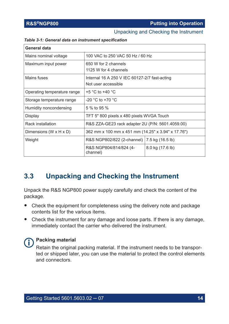
Table 3-1: General data on instrument specification
General data
Mains nominal voltage 100 VAC to 250 VAC 50 Hz / 60 Hz
Maximum input power 650 W for 2 channels1125 W for 4 channels
Mains fuses Internal 16 A 250 V IEC 60127-2/7 fast-actingNot user accessible
Operating temperature range +5 °C to +40 °C
Storage temperature range -20 °C to +70 °C
Humidity noncondensing 5 % to 95 %
Display TFT 5" 800 pixels x 480 pixels WVGA Touch
Rack installation R&S ZZA-GE23 rack adapter 2U (P/N: 5601.4059.00)
Dimensions (W x H x D) 362 mm x 100 mm x 451 mm (14.25" x 3.94" x 17.76")
Weight R&S NGP802/822 (2-channel) 7.5 kg (16.5 lb)
R&S NGP804/814/824 (4-channel)
8.0 kg (17.6 lb)
3.3 Unpacking and Checking the Instrument
Unpack the R&S NGP800 power supply carefully and check the content of thepackage.
● Check the equipment for completeness using the delivery note and packagecontents list for the various items.
● Check the instrument for any damage and loose parts. If there is any damage,immediately contact the carrier who delivered the instrument.
Packing materialRetain the original packing material. If the instrument needs to be transpor-ted or shipped later, you can use the material to protect the control elementsand connectors.
Unpacking and Checking the Instrument
Putting into OperationR&S®NGP800
15Getting Started 5601.5603.02 ─ 07
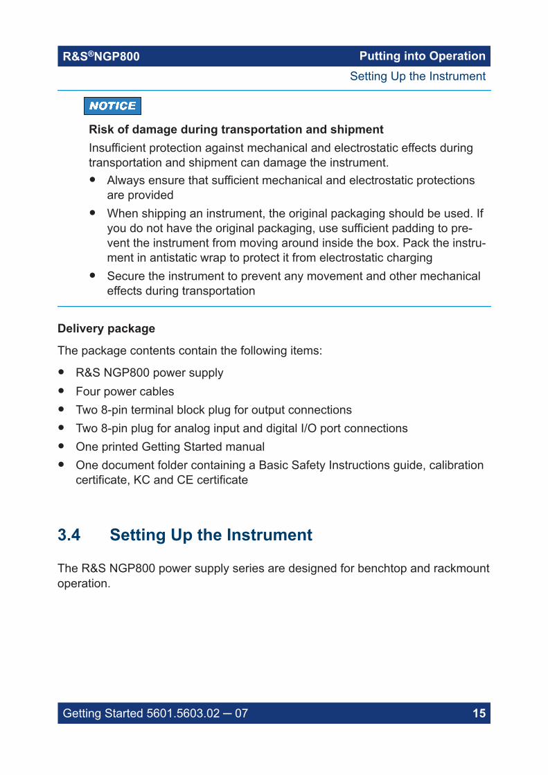
Risk of damage during transportation and shipmentInsufficient protection against mechanical and electrostatic effects duringtransportation and shipment can damage the instrument.● Always ensure that sufficient mechanical and electrostatic protections
are provided● When shipping an instrument, the original packaging should be used. If
you do not have the original packaging, use sufficient padding to pre-vent the instrument from moving around inside the box. Pack the instru-ment in antistatic wrap to protect it from electrostatic charging
● Secure the instrument to prevent any movement and other mechanicaleffects during transportation
Delivery package
The package contents contain the following items:
● R&S NGP800 power supply● Four power cables● Two 8-pin terminal block plug for output connections● Two 8-pin plug for analog input and digital I/O port connections● One printed Getting Started manual● One document folder containing a Basic Safety Instructions guide, calibration
certificate, KC and CE certificate
3.4 Setting Up the Instrument
The R&S NGP800 power supply series are designed for benchtop and rackmountoperation.
Setting Up the Instrument

Putting into OperationR&S®NGP800
16Getting Started 5601.5603.02 ─ 07
Risk of instrument damage due to high temperatureOperate R&S NGP800 power supply in an area where the ambient temper-ature is within +5 °C to +40 °C.The R&S NGP800 power supply is fan-cooled and must be installed withsufficient space on the sides to allow proper air circulation. Ensure that fanopenings are unobstructed and airflow vents are unimpeded.Operating the instrument with insufficient airflow or outside the allowableambient temperature can disrupt the operation and even cause damage.
3.4.1 Bench Operation
On a benchtop, the R&S NGP800 power supply can either lie flat or stand on itsfeet. As shown in Figure 3-1, feet on the bottom can be folded out to set theinstrument in an inclined position.
Figure 3-1: Inclined position
Positioning of instrumentThe instrument must be positioned in a manner that allows you to discon-nect the unit from the mains at any time and without restrictions.
Setting Up the Instrument
Putting into OperationR&S®NGP800
17Getting Started 5601.5603.02 ─ 07
Risk of injury if feet are folded outThe feet can fold in if they are not folded out completely or if the instrumentis shifted. Collapsing feet can cause injury or damage the instrument.● Fold the feet completely in or out to ensure stability of the instrument.
Never shift the instrument when the feet are folded out.● When the feet are folded out, do not work under the instrument or place
anything underneath.● The feet can break if they are overloaded. The overall load on the fol-
ded-out feet must not exceed 250 N.
3.4.2 Rack Mounting
The instrument can be installed in 19" rack using the rack adapter R&S ZZA-GE23 (P/N 5601.4059.00). Proceed according to the installation instructions sup-plied with the rack adapter.
Setting Up the Instrument

Instrument TourR&S®NGP800
18Getting Started 5601.5603.02 ─ 07
4 Instrument TourThis chapter provides an overview of all the controls available in theR&S NGP800 power supply series and steps to switch on the instrument for thefirst time.
● Overview of Controls.......................................................................................18● Switching On the Instrument........................................................................... 23
4.1 Overview of Controls
4.1.1 Front Panel
The front panel of the R&S NGP800 power supply is shown in Figure 4-1. Thefunction keys and navigation controls are located beside the display. The variousconnectors are located at the right of the display.
The following power supply models are available:
Table 4-1: Power supply models
Models Number of output channels
NGP802, NGP822 2
NGP804, NGP814, NGP824 4
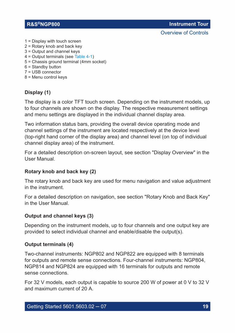
Figure 4-1: Front panel of R&S NGP800 power supply
Overview of Controls
Instrument TourR&S®NGP800
19Getting Started 5601.5603.02 ─ 07
1 = Display with touch screen2 = Rotary knob and back key3 = Output and channel keys4 = Output terminals (see Table 4-1)5 = Chassis ground terminal (4mm socket)6 = Standby button7 = USB connector8 = Menu control keys
Display (1)
The display is a color TFT touch screen. Depending on the instrument models, upto four channels are shown on the display. The respective measurement settingsand menu settings are displayed in the individual channel display area.
Two information status bars, providing the overall device operating mode andchannel settings of the instrument are located respectively at the device level(top-right hand corner of the display area) and channel level (on top of individualchannel display area) of the instrument.
For a detailed description on-screen layout, see section "Display Overview" in theUser Manual.
Rotary knob and back key (2)
The rotary knob and back key are used for menu navigation and value adjustmentin the instrument.
For a detailed description on navigation, see section "Rotary Knob and Back Key"in the User Manual.
Output and channel keys (3)
Depending on the instrument models, up to four channels and one output key areprovided to select individual channel and enable/disable the output(s).
Output terminals (4)
Two-channel instruments: NGP802 and NGP822 are equipped with 8 terminalsfor outputs and remote sense connections. Four-channel instruments: NGP804,NGP814 and NGP824 are equipped with 16 terminals for outputs and remotesense connections.
For 32 V models, each output is capable to source 200 W of power at 0 V to 32 Vand maximum current of 20 A.
Overview of Controls
Instrument TourR&S®NGP800
20Getting Started 5601.5603.02 ─ 07
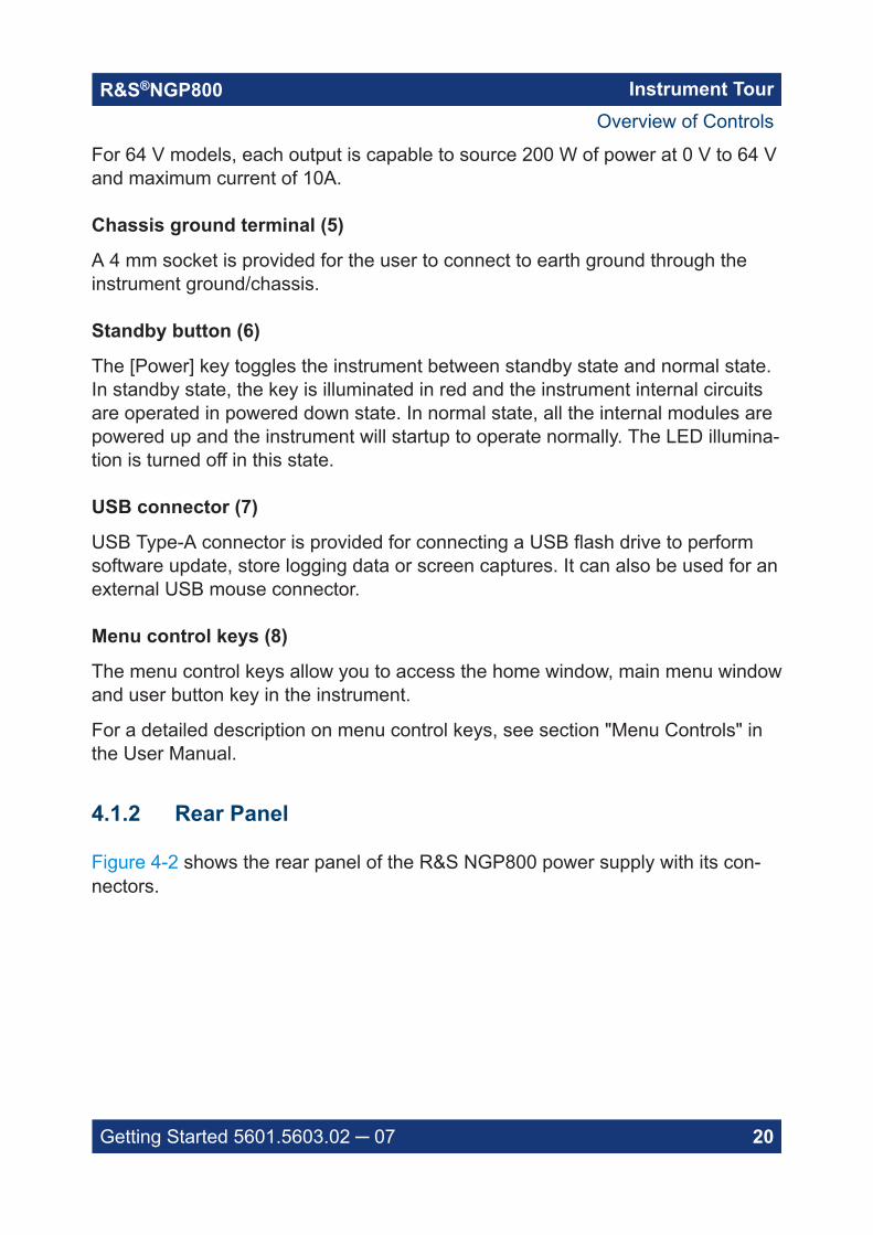
For 64 V models, each output is capable to source 200 W of power at 0 V to 64 Vand maximum current of 10A.
Chassis ground terminal (5)
A 4 mm socket is provided for the user to connect to earth ground through theinstrument ground/chassis.
Standby button (6)
The [Power] key toggles the instrument between standby state and normal state.In standby state, the key is illuminated in red and the instrument internal circuitsare operated in powered down state. In normal state, all the internal modules arepowered up and the instrument will startup to operate normally. The LED illumina-tion is turned off in this state.
USB connector (7)
USB Type-A connector is provided for connecting a USB flash drive to performsoftware update, store logging data or screen captures. It can also be used for anexternal USB mouse connector.
Menu control keys (8)
The menu control keys allow you to access the home window, main menu windowand user button key in the instrument.
For a detailed description on menu control keys, see section "Menu Controls" inthe User Manual.
4.1.2 Rear Panel
Figure 4-2 shows the rear panel of the R&S NGP800 power supply with its con-nectors.
Overview of Controls

Instrument TourR&S®NGP800
21Getting Started 5601.5603.02 ─ 07
Figure 4-2: Rear panel of R&S NGP800 power supply
9 = AC inlet with integrated 2-pole rocker switch10 = Optional IEEE-488 (GPIB) interface11 = Ground terminal12 = Kensington lock13 = Channel 3 and 4 rear panel connector (for NGP804, NGP814 and NGP824 models only)14 = Channel 1 and 2 rear panel connector15 = Analog input and digital I/O connector16 = USB-B connector (device)17 = Ethernet (LAN) connector
AC inlet with integrated 2-pole rocker switch (9)
Main supply cableUse only the power cable that was supplied with the instrument. Using othertypes, which might have inadequate rating can cause overheating of thepower cable, resulting in fire.The power cable provides the earth ground connection through the thirdground conductor. Operate the instrument only on authorized safety socketswhich provide earth connection.
The power cable must be plugged in before signal circuits can be connected.Never use the product if the power cable is damaged.
The built-in 2-pole rocker switch is the main power switch of the instrument whichconnects/disconnects it from the AC supply.
Overview of Controls
Instrument TourR&S®NGP800
22Getting Started 5601.5603.02 ─ 07
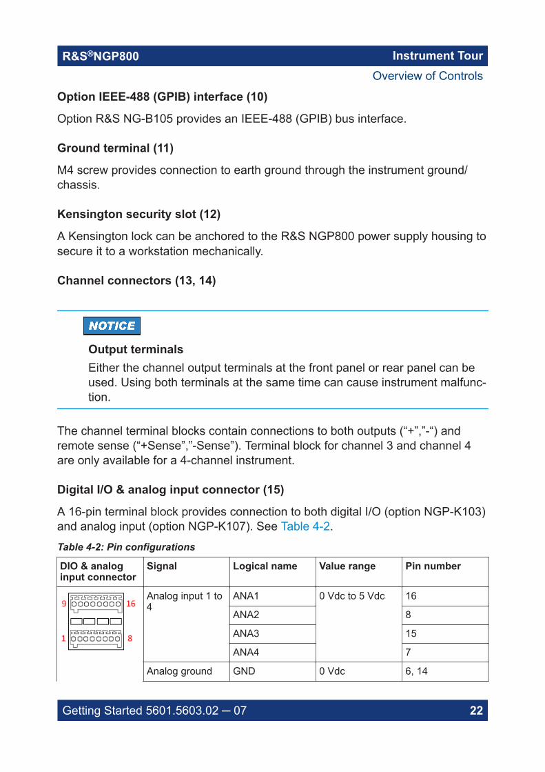
Option IEEE-488 (GPIB) interface (10)
Option R&S NG-B105 provides an IEEE-488 (GPIB) bus interface.
Ground terminal (11)
M4 screw provides connection to earth ground through the instrument ground/chassis.
Kensington security slot (12)
A Kensington lock can be anchored to the R&S NGP800 power supply housing tosecure it to a workstation mechanically.
Channel connectors (13, 14)
Output terminalsEither the channel output terminals at the front panel or rear panel can beused. Using both terminals at the same time can cause instrument malfunc-tion.
The channel terminal blocks contain connections to both outputs (“+”,”-“) andremote sense (“+Sense”,”-Sense”). Terminal block for channel 3 and channel 4are only available for a 4-channel instrument.
Digital I/O & analog input connector (15)
A 16-pin terminal block provides connection to both digital I/O (option NGP-K103)and analog input (option NGP-K107). See Table 4-2.
Table 4-2: Pin configurations
DIO & analoginput connector
Signal Logical name Value range Pin number
Analog input 1 to4
ANA1 0 Vdc to 5 Vdc 16
ANA2 8
ANA3 15
ANA4 7
Analog ground GND 0 Vdc 6, 14
Overview of Controls

Instrument TourR&S®NGP800
23Getting Started 5601.5603.02 ─ 07
DIO & analoginput connector
Signal Logical name Value range Pin number
Digital ground GND 0 Vdc 5, 13
Digital trigger 1 to8
DIO1 TTL 12
DIO2 4
DIO3 11
DIO4 3
DIO5 10
DIO6 2
DIO7 9
DIO8 1
USB connector (16)
USB Type-B connector provides remote control operation via USB.
Ethernet connector (17)
10/100 Ethernet port for remote control operation via the local area network.
4.2 Switching On the Instrument
Before switching on the instrument, check that all the instructions in the “BasicSafety Instruction” brochure and safety measures in previous sections areobserved.
To switch on instrument:
1. Connect the power cable to the AC power connector at the rear panel of theR&S NGP800 power supply.
2. Connect the power cable to the socket outlet.
3. Toggle the power rocker switch at the rear panel to turn on the instrument.The instrument performs a system check, boots the operating system, andstarts the R&S NGP800 power supply firmware.
Switching On the Instrument
Instrument TourR&S®NGP800
24Getting Started 5601.5603.02 ─ 07
It takes a few seconds for the power supply to complete the initialization before itis ready for use. If the instrument does not turn on, verify that the power cord issecurely plugged-in and power is available at the outlet. Check if the standbypower is lit at the [Power] key on the front panel. If the standby power is lit, pressthe [Power] key to initiate the start-up sequence.
To switch off instrument:
1. Press the [Power] key.The R&S NGP800 power supply initializes the power down sequence andenters into standby mode. The R&S NGP800 operates at low power.
2. Toggle the rocker switch at the rear panel to turn off the instrument completely.
3. Disconnect the AC power cable from the socket outlet.
Switching On the Instrument

Trying Out the InstrumentR&S®NGP800
25Getting Started 5601.5603.02 ─ 07
5 Trying Out the InstrumentThis chapter describes some basic functions that you can perform with theR&S NGP800 power supply series.
5.1 Setting the Output Voltage and Current Limit
1. Press [Home] key.The R&S NGP800 power supply displays the home window.
2. Select voltage or current parameter of the desired channel.The R&S NGP800 power supply displays an on-screen keypad to set thevalue.
Setting the Output Voltage and Current Limit

Trying Out the InstrumentR&S®NGP800
26Getting Started 5601.5603.02 ─ 07
3. Enter the required value.
4. Confirm value with either a unit key or enter key .The home window shows the updated voltage and current settings (Seechanges of voltage and current values in channel 1).
5. Repeat for other channel if desired.
5.2 Activating the Channels Output
The output voltages can be switched on or off regardless of the instrument's oper-ating mode.
Activating the Channels Output
Trying Out the InstrumentR&S®NGP800
27Getting Started 5601.5603.02 ─ 07
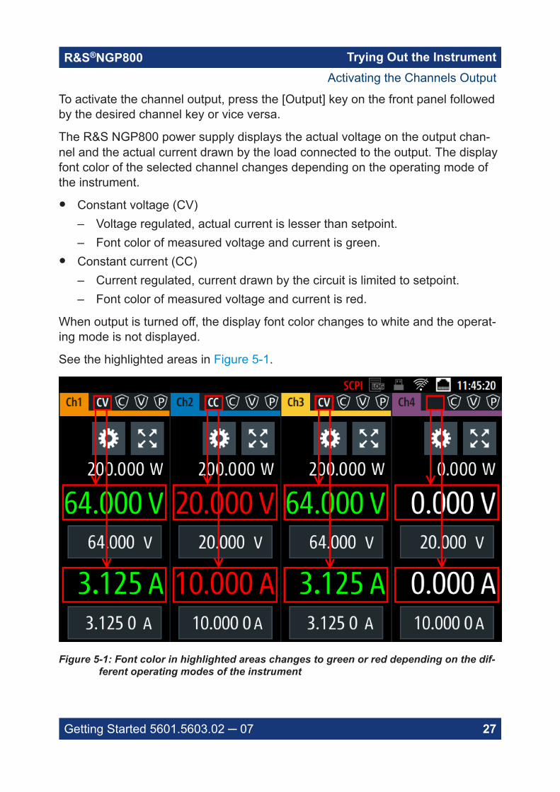
To activate the channel output, press the [Output] key on the front panel followedby the desired channel key or vice versa.
The R&S NGP800 power supply displays the actual voltage on the output chan-nel and the actual current drawn by the load connected to the output. The displayfont color of the selected channel changes depending on the operating mode ofthe instrument.
● Constant voltage (CV)– Voltage regulated, actual current is lesser than setpoint.– Font color of measured voltage and current is green.
● Constant current (CC)– Current regulated, current drawn by the circuit is limited to setpoint.– Font color of measured voltage and current is red.
When output is turned off, the display font color changes to white and the operat-ing mode is not displayed.
See the highlighted areas in Figure 5-1.
Figure 5-1: Font color in highlighted areas changes to green or red depending on the dif-ferent operating modes of the instrument
Activating the Channels Output

Maintenance and SupportR&S®NGP800
28Getting Started 5601.5603.02 ─ 07
6 Maintenance and Support
6.1 Maintenance
Regular maintenance improves the life span of the instrument, the following chap-ter provides information on instrument maintenance.
Cleaning
Before cleaning the instrument, ensure that it has been switched off and thepower cable is disconnected.
Clean the outer case of the instrument at regular intervals, using a soft, lint-freedust cloth.
Instrument damage caused by cleaning agentsUse a dry, lint-free cloth to clean the product. When cleaning, keep in mindthat the casing is not waterproof. Do not use any liquids for cleaning.Cleaning agents, solvents (thinners, acetone), acids and bases can dam-age the front panel labeling, plastic parts and display.
The display may only be cleaned with an appropriate glass cleaner. Rub the dis-play with a dry, clean and lint-free cloth. Do not allow cleaning fluid to enter theinstrument.
Internal battery replacement
An internal CR2032 coin cell battery powers the real-time clock circuit which pro-vides continuous time stamp for the instrument. If the battery fails, the systemclock and time stamp for the logging function are not available but other instru-ment functions are not affected.
Under normal usage at room temperature, the battery is expected to last up to 10years. However, the battery life expectancy is reduced if the device is stored attemperature above 40°C for an extended period of time.
Maintenance
Maintenance and SupportR&S®NGP800
29Getting Started 5601.5603.02 ─ 07
If the instrument cannot retain the date and time settings after turning off theAC input, the battery is discharged.Contact your local service partner for battery replacement.
6.2 Contacting Customer Support
Technical support – where and when you need it
For quick, expert help with any Rohde & Schwarz product, contact our customersupport center. A team of highly qualified engineers provides support and workswith you to find a solution to your query on any aspect of the operation, program-ming or applications of Rohde & Schwarz products.
Contact information
Contact our customer support center at www.rohde-schwarz.com/support, or fol-low this QR code:
Figure 6-1: QR code to the Rohde & Schwarz support page
Contacting Customer Support

IndexR&S®NGP800
30Getting Started 5601.5603.02 ─ 07
Index
C
Calibration certificate ................................. 6Controls ................................................... 18Customer support .................................... 29
D
Delivery package contents ...................... 15Documentation overview ........................... 5
E
Electrostatic discharge .............................. 9ESD ........................................................... 9
F
Front panelBack key ............................................. 19Chassis ground terminal ..................... 20Display ................................................ 19Menu control keys ...............................20Output and channel keys .................... 19Output terminals ................................. 19Power key ........................................... 20Rotary knob ........................................ 19USB connector ....................................20
G
Getting Started .......................................... 5
I
Instrument tour ........................................ 18Overview controls ............................... 18Switching NGP on off ..........................23
Intended operation .................................. 12
M
MaintenanceCleaning ..............................................28Internal battery replacement ............... 28
O
Open source acknowledgment (OSA) ....... 6Overview controls
Front panel ..........................................18Rear panel .......................................... 20
P
Putting into operation ............................... 9Intended operation ..............................12Safety .................................................. 11Unpacking and checking the instrument............................................................14
R
Rear panelAC inlet with integrated 2-pole rockerswitch ..................................................21Analog input connector ....................... 22Channel connectors ............................22Digital I/O connector ........................... 22Ethernet connector ............................. 23Ground terminal .................................. 22IEEE-488 (GPIB) interface ..................22Kensington security slot .....................22USB connectors ..................................23
Release notes ........................................... 6
S
Safety ...................................................... 11Safety instructions ..................................... 5Setting up the instrument ........................ 15
Bench operation ..................................16Rack mounting ....................................17
Switching off the instrument .................... 24Switching on the instrument .................... 23
T
Trying out the instrumentActivating the channels output ............26Selecting the channels ........................25Setting the output voltage and currentlimit ..................................................... 25
U
Unpacking and checking the instrument . 14User manual .............................................. 5
W
Welcome to R&S NGP800 ........................ 7