Rama Doss 2015
6
A Simple Microcontroller Based Digitizer for Differential Inductive Sensors Nandagopal Ramadoss, Student Member, IEEE and Boby George, Member, IEEE Department of Electrical Engineering, Indian Institute of technology Madras, India. e-mail : [email protected] Abstract—This paper presents a simple digitizer suitable for differential variable inductive/reluctance sensors. The proposed scheme uses two digital I/O pins, a counter and a comparator of a microcontroller and obtains a digital output directly proportional to the measurand which is sensed using a differential variable inductive/reluctance sensor possessing either a linear or an inverse transfer characteristic. The scheme uses a ratio-metric approach in the computation and hence the output is less sensitive to variation in the parameters such as excitation voltage, reference voltage, offset of the comparator, etc. A prototype of the proposed system has been built and tested using standard variable inductors that emulated a differential inductive sensor following an inverse characteristic. The output recorded was linear across the full range and worst-case error noted was less than 0.3 %. For the prototype developed, the time taken to complete a measurement was 200 s. The prototype digitizer has been interfaced with a commercially available LVDT and tested. The worst-case error observed in this test was 0.77%. Also, the same digitizer has been employed to get a digital readout from a differential variable reluctance based displacement sensor. The worst-case error was less than 0.83%. The test results establish the efficacy of, the simple and cost effective, scheme developed. Keywords—Differential inductive sensor; Digitizer; microcontroller interface; linearization; timer-counter; DVRT; LVDT I. INTRODUCTION Inductive sensors are widely used in various industrial applications for sensing the displacement [1], proximity [2], pressure [3], position [4], etc. There are inductive/variable reluctance/eddy current based sensors that use a single coil [1], [3] for sensing. There are also differential inductive sensors with two coils where the inductances change in a push-pull/differential manner, with respect to the measurand [2], [4], [5]. Sensors with multiple coils/loops [6] are also in use. Some of the inductive sensors possess a linear relationship between the quantity being measured [4] and the inductance, for a limited range, while inductive/reluctance sensors that possess an inverse characteristic [7], [8] are also available in the market. Differential variable reluctance/inductive sensors with linear characteristic can be represented as in (1) and that with inverse characteristic [8] can be represented as in (2). In (1) and (2) k indicates the transformation constant of the sensor while x is the measurand. L 0 is the nominal value of the inductance at x = 0. kx L L 1 0 1 and kx L L 1 0 2 (1) kx L L 1 0 1 and kx L L 1 0 2 (2) Conventional methods of measurement of inductance of sensors rely on, tedious, bridge balancing. Later, with the help of electronic systems, the inductance measurement became less cumbersome. The quazi-balanced [9] and modified Maxwell-Wien bridge [10] schemes are examples of such improvements. The wide spread use of digital systems for storage and processing enforced the conventional measurement circuits to employ an Analog to Digital Converter (ADC) to enable the transfer of data to the digital systems. A DSP [6] based scheme reported for differential variable reluctance transducers is such an example. This type of requirement lead to the development of signal conditioning units that provide direct digital output proportional to the measurand, e. g., the inductance-to-digital converter based on dual-slope principle, presented in [8], which is well suitable for low speed applications. Direct interface circuits (direct microcontroller to sensor) suitable for resistive and capacitive sensors have been reported [11]. These circuits make use of the change in R-C time constant of R-C series circuit, i.e., when one of the elements changes (either R or C) with respect to the measurand while the other element is kept constant. A time period which is a function of the time constant of the circuit is measured using a counter module in the microcontroller [11]. A similar approach can be used for measurement of inductance. The principle behind measurement of the time constant of an R-L circuit has been presented in [12] while a basic idea of a microcontroller interface for measurement of an unknown inductance, in terms of a reference inductor, has been reported in [13]. Among the methods listed above, the DSP [6] and dual-slope [8] based schemes can be used to obtain a direct digital output from a differential reluctance/inductive sensor but they are complex and expensive. A new simple direct interface scheme, suitable for obtaining a digital output proportional to the quantity being sensed by a differential inductive/reluctance based sensor is presented in this paper. The scheme is suitable for differential type inductive sensors following either linear, as in (1), or inverse, as in (2), characteristic. It employs a ratio-metric approach [8], hence the effect of variation in various circuit parameters in the final output is negligible. The operation of the scheme, details of the prototype developed and test results after interfacing it with an LVDT and a Differential Variable Reluctance Transducer (DVRT) are presented in the sections below. This full text paper was peer-reviewed at the direction of IEEE Instrumentation and Measurement Society prior to the acceptance and publication. 978-1-4799-6144-6/15/$31.00 ©2015 IEEE
-
Upload
ubaidulla-rasheed -
Category
Documents
-
view
224 -
download
1
description
rama
Transcript of Rama Doss 2015

A Simple Microcontroller Based Digitizer for
Differential Inductive Sensors
Nandagopal Ramadoss, Student Member, IEEE and Boby George, Member, IEEE
Department of Electrical Engineering, Indian Institute of technology Madras, India. e-mail : [email protected]
Abstract—This paper presents a simple digitizer suitable for
differential variable inductive/reluctance sensors. The proposed
scheme uses two digital I/O pins, a counter and a comparator of a
microcontroller and obtains a digital output directly proportional
to the measurand which is sensed using a differential variable
inductive/reluctance sensor possessing either a linear or an
inverse transfer characteristic. The scheme uses a ratio-metric
approach in the computation and hence the output is less
sensitive to variation in the parameters such as excitation voltage,
reference voltage, offset of the comparator, etc. A prototype of
the proposed system has been built and tested using standard
variable inductors that emulated a differential inductive sensor
following an inverse characteristic. The output recorded was
linear across the full range and worst-case error noted was less
than 0.3 %. For the prototype developed, the time taken to
complete a measurement was 200 s. The prototype digitizer has
been interfaced with a commercially available LVDT and tested.
The worst-case error observed in this test was 0.77%. Also, the
same digitizer has been employed to get a digital readout from a
differential variable reluctance based displacement sensor. The
worst-case error was less than 0.83%. The test results establish
the efficacy of, the simple and cost effective, scheme developed.
Keywords—Differential inductive sensor; Digitizer;
microcontroller interface; linearization; timer-counter; DVRT;
LVDT
I. INTRODUCTION
Inductive sensors are widely used in various industrial applications for sensing the displacement [1], proximity [2], pressure [3], position [4], etc. There are inductive/variable reluctance/eddy current based sensors that use a single coil [1], [3] for sensing. There are also differential inductive sensors with two coils where the inductances change in a push-pull/differential manner, with respect to the measurand [2], [4], [5]. Sensors with multiple coils/loops [6] are also in use. Some of the inductive sensors possess a linear relationship between the quantity being measured [4] and the inductance, for a limited range, while inductive/reluctance sensors that possess an inverse characteristic [7], [8] are also available in the market. Differential variable reluctance/inductive sensors with linear characteristic can be represented as in (1) and that with inverse characteristic [8] can be represented as in (2). In (1) and (2) k indicates the transformation constant of the sensor while x is the measurand. L0 is the nominal value of the inductance at x = 0.
kxLL 101 and kxLL 102 (1)
kx
LL
1
01 and
kx
LL
1
02 (2)
Conventional methods of measurement of inductance of sensors rely on, tedious, bridge balancing. Later, with the help of electronic systems, the inductance measurement became less cumbersome. The quazi-balanced [9] and modified Maxwell-Wien bridge [10] schemes are examples of such improvements. The wide spread use of digital systems for storage and processing enforced the conventional measurement circuits to employ an Analog to Digital Converter (ADC) to enable the transfer of data to the digital systems. A DSP [6] based scheme reported for differential variable reluctance transducers is such an example. This type of requirement lead to the development of signal conditioning units that provide direct digital output proportional to the measurand, e. g., the inductance-to-digital converter based on dual-slope principle, presented in [8], which is well suitable for low speed applications. Direct interface circuits (direct microcontroller to sensor) suitable for resistive and capacitive sensors have been reported [11]. These circuits make use of the change in R-C time constant of R-C series circuit, i.e., when one of the elements changes (either R or C) with respect to the measurand while the other element is kept constant. A time period which is a function of the time constant of the circuit is measured using a counter module in the microcontroller [11]. A similar approach can be used for measurement of inductance. The principle behind measurement of the time constant of an R-L circuit has been presented in [12] while a basic idea of a microcontroller interface for measurement of an unknown inductance, in terms of a reference inductor, has been reported in [13]. Among the methods listed above, the DSP [6] and dual-slope [8] based schemes can be used to obtain a direct digital output from a differential reluctance/inductive sensor but they are complex and expensive.
A new simple direct interface scheme, suitable for obtaining a digital output proportional to the quantity being sensed by a differential inductive/reluctance based sensor is presented in this paper. The scheme is suitable for differential type inductive sensors following either linear, as in (1), or inverse, as in (2), characteristic. It employs a ratio-metric approach [8], hence the effect of variation in various circuit parameters in the final output is negligible. The operation of the scheme, details of the prototype developed and test results after interfacing it with an LVDT and a Differential Variable Reluctance Transducer (DVRT) are presented in the sections below.
This full text paper was peer-reviewed at the direction of IEEE Instrumentation and Measurement Society prior to the acceptance and publication.
978-1-4799-6144-6/15/$31.00 ©2015 IEEE
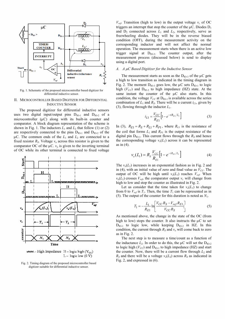
Fig. 1. Schematic of the proposed microcontroller based digitizer for
differential inductive sensor.
Fig. 2. Timing diagram of the proposed microcontroller based
digitizer suitable for differential inductive sensor.
II. MICROCONTROLLER BASED DIGITIZER FOR DIFFERENTIAL
INDUCTIVE SENSOR
The proposed digitizer for differential inductive sensors
uses two digital input/output pins DIO-1 and DIO-2 of a
microcontroller (C) along with its built-in counter and
comparator. A block diagram representation of the scheme is
shown in Fig. 1. The inductors L1 and L2 that follow (1) or (2)
are respectively connected to the pins DIO-1 and DIO-2 of the
C. The common ends of the L1 and L2 are connected to a
fixed resistor RS. Voltage vo across this resistor is given to the
comparator OC of the C. vo is given to the inverting terminal
of OC while its other terminal is connected to fixed voltage
Vref. Transition (high to low) in the output voltage vc of OC
triggers an interrupt that stop the counter of the C. Diodes D1
and D2 connected across L1 and L2, respectively, serve as
freewheeling diodes. They will be in the reverse biased
condition (OFF), during the measurement activity on the
corresponding inductor and will not affect the normal
operation. The measurement starts when there is an active low
trigger signal at DIO-3. The counter output, after the
measurement process (discussed below) is send to display
using a digital port.
A. A C Based Digitizer for the Inductive Sensor
The measurement starts as soon as the DIO-3 of the C gets
a high to low transition as indicated in the timing diagram in
Fig. 2. The moment DIO-3 goes low, the C sets DIO-1 to logic
high (VCC) and DIO-2 to high impedance (HZ) state. At the
same instant the counter of the C also starts. In this
condition, the voltage VCC at DIO-1 is available across the series
combination of L1 and RS. There will be a current iL1, given by
(3), flowing through the inductor L1.
1111
1LRt
E
CCL
EeR
Vi
(3)
In (3), 111 PLSE RRRR , where RL1 is the resistance of
the coil that forms L1 and RP1 is the output resistance of the
digital pin DIO-1. This current flows through the RS and hence
the corresponding voltage vo(L1) across it can be represented
as in (4).
111)(1
1
LRt
E
CCSo
EeR
VRLv
(4)
The vo(L1) increases in an exponential fashion as in Fig. 2 and
in (4), with an initial value of zero and final value as VCC. The
output of OC will be high until vo(L1) reaches Vref. When
vo(L1) crosses Vref, the comparator output vc will change from
high to low and stop the counter as illustrated in Fig. 2.
Let us consider that the time taken for vo(L1) to change
from 0 to Vref is T1. Then, the time T1 can be represented as in
(5). The output of the counter for this duration is noted as N1.
SCC
ErefSCC
E RV
RVRV
R
LT
1
1
11 ln (5)
As mentioned above, the change in the state of the OC (from
high to low) stops the counter. It also instructs the C to set
DIO-1 to logic low, while keeping DIO-2 in HZ. In this
condition, the current through RS and vo will come back to zero
as in Fig. 2.
The next step is to measure a time/count as a function of
the inductance L2. In order to do this, the C will set the DIO-2
to logic high (VCC) and DIO-1 to high impedance (HZ) and start
the counter. Now, there will be a current flow through L2 and
RS and there will be a voltage vo(L2) across RS as indicated in
Fig. 2, and expressed in (6).

Fig. 3. Flowchart of the sequence of operations during a measurement
cycle.
221)(2
2LRt
E
CCSo
EeR
VRLv
(6)
In equation (6), 222 PLSE RRRR , where RL2 is the coil
resistance of inductor L2 and RP2 is the output resistance of the
pin DIO-2. As in the case of vo(L1), the voltage vo(L2) will also
increase with time and reach Vref, say at time T2, as illustrated
in Fig. 2. At this instant, vc will change from high to low, and
generate an interrupt to stop the counter and set DIO-2 to low
and keep DIO-1 in HZ. This will bring the vo(L2) to zero. The
time T2 can be expressed as in (7). The corresponding output
from the counter is noted as N2 as illustrated in Fig. 2.
SCC
ErefSCC
E RV
RVRV
R
LT
2
2
22 ln (7)
Now, if we consider that RE1 = RE2 and perform a ratio-
metric operation as in (8), we can observe that the outcome is
independent of VCC, Vref, RS and RE. The resistances of the
coils of differential inductive sensors usually have very small
mismatch , similarly, the output resistances of the digital pins
(DIO-1 and DIO-2) employed are also considered to have very
small mismatch (less than 0.5 ). If there is a small mismatch
in the resistance values of the coils, it can be corrected by
introducing an additional resistance in the lowest resistance
path.
21
21
21
21
21
21
LL
LL
NN
NN
TT
TT
(8)
If we substitute for L1 and L2 in (8) as given in (1), the linear
characteristic, we get the measurand kx as
21
21
NN
NNkx
. (9)
The expression (9) for output will remain same even if we use
the inductive sensor that follows the inverse characteristic as
in (2). Thus, the digital ratio-metric output, of the counter
outputs N1 and N2, is directly proportional to the measurand.
Details of the prototype developed and test results are given in
the section below.
III. EXPERIMENTAL SETUP AND RESULTS
A prototype of the proposed scheme has been realized
using off-the-shelf items to evaluate the practicability of the
digitizer for differential inductive sensor. The entire prototype
system was built using a single microcontroller and a few
additional components. The microcontroller employed was IC
ATSAM3x8E [14] from ATMEL Corporation. The
Timer/Counter module of the microcontroller was used to
implement the counters that count and provide N1 and N2. This
counter module can measure time with a resolution of 23.8 ns.
The comparator was realized using a high speed comparator
IC LM311P [15]. This generates the interrupt to stop the
counter, whenever vo crosses Vref. The microcontroller DIO’s
are used for realizing start trigger input, counter interrupt input
(vC) and excitation outputs (DIO-1 and DIO-2). To achieve
precise execution control and timing; PORT - D (<D1:2> and
<D9:10>) and Timer/Counter-1 module was used to
implement the measurement scheme as they are not
multiplexed with any other functionality.
The value of resistor RS used was 150 Ω; this was fixed as
a better tradeoff between time constant of the R-L circuit and
output current sourcing capacity (< 25 mA) of the digital I/O
pin of the microcontroller. The non-inverting input of the
comparator OC was connected to a reference voltage
Vref = 1.65 V. This reference value was finalized based on the
SPICE simulation studies conducted to understand the best
value of Vref to obtain the best change in voltage of vo to noise
ratio for a range of values of inductances (10 mH to 60 mH)
used to test the prototype in the first stage of testing. The
inverting input of the OC was connected to the voltage vo
across RS. The output of OC was connected to the interrupt
input pin of the microcontroller. The freewheeling diodes D1
and D2 were implemented using IN4148. A suitable program
as per the flow chart given in Fig. 3. was developed and
loaded into the microcontroller using Ardunio IDE with DUE
hardware. Outputs of the counters were transferred and
displayed in a computer through serial communication.
In order to test the prototype developed, two standard
variable inductors, manufactured by General Radio Company,
Massachusetts, were used whose values can be set as per (1)
or (2) to emulate the differential inductive sensor. The variable
inductors were realized using two mutually coupled inductors
having self-inductance value of 19.90 mH. The effective
inductance of each unit can be varied from 6.00 mH to
50.00 mH by varying the mutual coupling between the
inductors. To emulate the differential sensor as in (2), the
above-mentioned standard inductors were set initially at
12 mH. This was taken as the nominal inductance L0. Then,
the required inductance values, as per (2), for every step of
increase in kx equal to 0.05 were computed. The standard
inductors were set to those values computed and
corresponding N1 and N2 values were recorded. The
measurement was repeated for 10 times for every set of kx and
the average value was displayed in the computer. To complete
one cycle of measurement the developed system took less than

Fig. 4. A photograph of the experimental set-up. The microcontroller and
a small PCB with the comparator IC and terminals to connect the
inductors and probes are visible. The standard inductor boxes used, for the initial tests, and oscilloscope that indicate the important waveforms
are also visible in the picture.
Fig. 5. Snap-shot of the waveforms observed in an oscilloscope during the
experiment.
Fig. 6. The counts N1 and N2 noted from the microcontroller
corresponding to the values of L1 and L2 [set as per equation (2)]. L0
was set as 12 mH, in this experimental study. The value of kx computed using N1 and N2 as per (9) and the error in each
measurement are indicated.
Fig. 7. Experimental set-up developed to test the microcontroller based
interface with a commercially available LVDT.
200 s.
A photograph of the experimental set-up is given in Fig. 4.
The important waveforms from the prototype were observed
in a mixed signal oscilloscope MSO6034A from Agilent
Technologies. A snap-shot of the waveforms recorded is
shown in Fig. 5. The time durations T1 and T2 were measured
in the oscilloscope and count values N1 and N2 from the
microcontroller were compared. These values were found to
be matched with the theoretical values computed using SPICE
tools. Fig. 6 shows a plot of values N1 and N2 measured using
the counter of the microcontroller when L1 and L2 were varied
as per (2), i.e., inverse characteristic. It also shows the ratio-
metric output computed, as per (9), using the counter outputs
and the error in each reading. The worst-case error in the
output for the range tested was found to be less than 0.3 %.
The sources of the error include mismatch between RL1 and
RL2, RP1 and RP2 [11], noise, etc. The results show that the
proposed scheme is a promising, simple and low cost, method
for obtaining a direct digital output from the differential
reluctance/inductive sensors.
A. Testing with an LVDT
In order to assess the performance of the scheme in
practical applications, a few more tests were conducted. In one
of the tests, the prototype measurement unit developed was
interfaced with a commercially available a.c. type LVDT
(range of 0-25 mm), manufactured by Spranktronics,
Bangalore and experiments were conducted. A photograph of
the experimental set-up is shown in Fig. 7. The two secondary
coils of the LVDT were connected to the measurement unit as
illustrated (L1 and L2) in Fig. 1. The primary of the LVDT was
not used. Resistance RL1 of the coil with inductance L1 was
68.8 , while that of L2 was RL2 = 68.5 . In the test set-up,
the plunger rod of the LVDT was connected to a precision
displacement unit based on a screw gauge arrangement which
has a resolution of 10 m. The inductance values (L1 and L2)
of the secondary coils were measured using the prototype unit
developed, for a range of displacement of 15 mm in every
steps of 1 mm. Value of kx was then calculated as in (9) and
the displacement measured was computed. The counter
outputs N1 and N2, measured output x (displacement),
percentage error observed in each measurement are plotted
and given in Fig. 8. The results show that the proposed simple
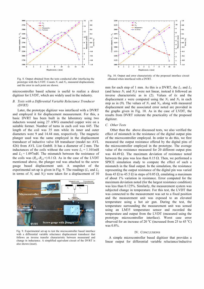
Fig. 10. Output and error characteristic of the proposed interface circuit
obtained when interfaced with a DVRT.
Fig. 8. Output obtained from the tests conducted after interfacing the
prototype with the LVDT. Counts N1 and N2, measured displacement,
and the error in each point are shown.
Fig. 9. Experimental set-up to test the microcontroller based interface
with a differential variable reluctance displacement transducer that
follows an inverse transfer characteristic between measurand and change in inductance. A simplified equivalent circuit of the DVRT is
also shown (inset).
microcontroller based scheme is useful to realize a direct
digitizer for LVDT, which are widely used in the industry.
B. Tests with a Differential Variable Reluctance Trsnducer
(DVRT)
Later, the prototype digitizer was interfaced with a DVRT
and employed it for displacement measurement. For this, a
basic DVRT has been built in the laboratory using two
inductors wound using 27 AWG enameled copper wire on a
suitable former. Number of turns in each coil was 645. The
length of the coil was 35 mm while its inner and outer
diameters were 9 and 14.44 mm, respectively. The magnetic
plunger used was the same employed in the displacement
transducer of inductive valve lift transducer (model no: AVL
426) from AVL List GmbH. It has a diameter of 2 mm. The
inductances of the coils without the core were L1 = 1.101mH
and L2 = 1.097mH. The mismatch between the resistance of
the coils was (RL1-RL2 =) 0.1 . As in the case of the LVDT
mentioned above, the plunger rod was attached to the screw
gauge based displacement unit. A snapshot of the
experimental set-up is given in Fig. 9. The readings (L1 and L2
in terms of N1 and N2) were taken for a displacement of 10
mm for each step of 1 mm. As this is a DVRT, the L1 and L2
(and hence N1 and N2) were not linear, instead it followed an
inverse characteristic as in (2). Values of kx and the
displacement x were computed using the N1 and N2 in each
step as in (9). The values of N1 and N2, along with measured
displacement and the associated error noted are provided in
the graphs given in Fig. 10. As in the case of LVDT, the
results from DVRT reiterate the practicality of the proposed
digitizer.
C. Other Tests
Other than the above discussed tests, we also verified the
effect of mismatch in the resistance of the digital output pins
of the microcontroller employed. In order to do this, we first
measured the output resistance offered by the digital pins of
the microcontroller employed in the prototype. The average
value of the resistance measured for 20 different output pins
was 44.49 . The maximum deviation of resistance noted
between the pins was less than 0.15 . Then, we performed a
SPICE simulation study to compute the effect of such a
mismatch in the final output. In the simulation, the resistance
representing the output resistance of the digital pin was varied
from 45 to 45.5 in steps of 0.05 , emulating a maximum
of about 1% variation in resistance. Error computed for the
maximum deviation noted (for the largest resistance condition)
was less than 0.125%. Similarly, the measurement system was
subjected change in temperature. For this test, the LVDT that
was connected to the measurement was set to a fixed position
and the measurement unit was exposed to an elevated
temperature using a hot air gun. During the test, the
temperature surrounding the measurement unit was sensed
using an LM35 temperature sensor and recorded the
temperature and output from the LVDT (measured using the
prototype microcontroller interface). Worst case error
observed for an increase of 20 oC (increased from 25 to 45
oC)
was 0.8%.
IV. CONCLUSIONS
A simple microcontroller based digitizer that provides a
linear output for differential variable reluctance/inductive

sensor possessing either a linear or an inverse characteristic
has been developed and the technical details are presented in
this paper. The presented scheme uses the digital input/output
pins, comparator and counter of a microcontroller system, to
realize the digitizer. It does not require an ADC hence a basic
microcontroller with sufficiently high clock frequency will be
enough to realize the proposed scheme. A prototype of the
scheme has been developed and tested using standard
inductance boxes, emulating the differential sensor with
inverse characteristic. The output from the prototype unit was
linear for the entire range tested, with a worst-case error less
than 0.3 %. The developed digitizer is useful for differential
variable reluctance transducers for displacement measurement
[6], [16], inductive differential pressure transducers [8], etc.
As the measurement unit is very compact, it can be easily
integrated within the sensor housing itself. The measurement
system developed has also been employed to obtain a digital
output from a commercially available LVDT and a DVRT.
The test results using these sensors show the practical use of
the proposed scheme.
REFERENCES
[1] D. Vyroubal, “Eddy-current displacement transducer with extended linear range and automatic tuning,” IEEE Trans. Instrum. Meas., vol. 58, no. 9, pp. 3221-3231, Sep. 2009.
[2] B. George, H. Zangl, T. Bretterklieber, and G. Brasseur, “A combined inductive–capacitive proximity sensor for seat occupancy detection,” IEEE Trans. Instrum. Meas., vol. 59, no. 5, pp. 1463-1470, May 2010.
[3] E. G. Bakhoum and M. H. M. Cheng, “High-sensitivity inductive pressure sensor,” IEEE Trans. Instrum. Meas., vol. 60, no. 8, pp. 2960-2966, Aug. 2011.
[4] A. Masi, A. Danisi, R.Losito, M. Martino and G. Spiezia, “Study of magnetic interference on a LVDT prototype,” in Proc. IEEE I2MTC, Austin, Texas, May 2010, pp. 219-223,.
[5] A. Flammini, D. Marioli, E. Sisinni and A. Taroni, “A multichannel DSP-based instrument for displacement measurement using differential variable reluctance transducer,” IEEE Trans. Instrum. Meas., vol. 54, no. 1, pp. 178-183, Feb. 2005.
[6] S. S. M. Ali, B. George, and L. Vanajakshi, “An Efficient Multiple-Loop Sensor Configuration Applicable for Undisciplined Traffic,” IEEE Trans. Intel. Trans. Sys., vol. 14, no. 3, pp. 1151-1161, Sept. 2013.
[7] M. R. Nabavi and S. Nihtianov, “A novel interface for eddy current displacement sensors,” IEEE Trans. Instrum. Meas., vol. 58, no. 5, pp. 1623-1632, May 2009.
[8] V. N. Philip and B. George, “Design and Analysis of a Dual-Slope Inductance-to-Digital Converter for Differential Reluctance Sensors,” IEEE Trans. Instrum. Meas., vol. 63, no. 5, pp. 1364-1371, May 2014.
[9] M. A. Atmanand, V. J. Kumar, and V. Murti, “A microcontroller-based quasi-balanced bridge for the measurement of L, C and R,” IEEE Trans. Instrum. Meas., vol. 45, no. 3, pp. 757-761, Jun. 1996.
[10] S. Chattopadhyay and S. C. Bera, “Modification of the Maxwell–Wien bridge for accurate measurement of a process variable by an inductive transducer,” IEEE Trans. Instrum. Meas., vol. 59, no. 9, pp. 2445-2449, Sep. 2010.
[11] F. Reverter, “Power consumption in direct interface circuits,” IEEE Trans. Instrum. Meas., vol. 62, no. 2, pp. 503-509, Feb. 2013.
[12] Application Note, AN1375, “See What You Can Do with the CTMU, Microchip Technology Inc.”, Feb. 1999.
[13] Kokolanski, Zivko, Josep Jordana, Manel Gasulla, Vladimir Dimcev, and Ferran Reverter. "Microcontroller-based Interface Circuit for Inductive Sensors." Procedia Engineering 87, pp. 1251-1254, 2014.
[14] Data Sheet: 11057BS–ATARM, 2012 Atmel Corporation, “AT91SAM ARM-based Flash MCU - SAM3X & SAM3A Series”.
[15] Data Sheet: SLCS007H, 2003 Texas Instruments Incorporated, “LM111, LM211, LM311 Differential comparators with strobes ”.
[16] Datasheet: Version 8400-0005 rev.001, Lord Microstrain, NC-DVRT, 2013, “Non-Contact displacement sensor”. [Online]. Available: http://files.microstrain.com/Non-Contact-DVRT-Data-Sheet.pdf


![DWARAKA DOSS GOVERDHAN DOSS VAISHNAV ... - dgvc physicsdgvcphysics.yolasite.com/resources/II M.Sc.Syllabus.pdf · VAISHNAV COLLEGE (Linguistic Minority Institution) [AUTONOMOUS] ...](https://static.fdocuments.in/doc/165x107/5a97f3897f8b9a8b5d8dbed3/dwaraka-doss-goverdhan-doss-vaishnav-dgvc-mscsyllabuspdfvaishnav-college.jpg)