RAISED ACCESS FLOORS AND OFFICE ACOUSTICS - Tate...
17
Raised Access Floors and Office Acoustics May 12, 2000 This paper addresses the most frequently asked acoustics questions pertaining to raised Flooring. The overriding question is whether unwanted sounds will be transmitted throughout an office environment due to the presence of a raised floor system. Laboratory and field tests conducted by Tate and many other organizations show that when using typical interior con- struction of either drywall partitions or demountable partitions with conventional suspended lay-in ceilings, the use of a Tate raised floor will not result in a perceptible loss of sound isolation from office to office. A Tate raised floor provides far greater sound isolation than is possible with standard wall systems and/or ceiling systems. The acoustical “weak link” within standard interior constructions will always be the walls and ceilings, due to their pen- etrations and or lower sound transmission performances.
Transcript of RAISED ACCESS FLOORS AND OFFICE ACOUSTICS - Tate...
Raised Access Floors and Office Acoustics
May 12, 2000
This paper addresses the most frequently asked acoustics questions pertaining to raised
Flooring. The overriding question is whether unwanted sounds will be transmitted throughout
an office environment due to the presence of a raised floor system. Laboratory and field tests
conducted by Tate and many other organizations show that when using typical interior con-
struction of either drywall partitions or demountable partitions with conventional suspended
lay-in ceilings, the use of a Tate raised floor will not result in a perceptible loss of sound
isolation from office to office. A Tate raised floor provides far greater sound isolation than is
possible with standard wall systems and/or ceiling systems. The acoustical “weak link”
within standard interior constructions will always be the walls and ceilings, due to their pen-
etrations and or lower sound transmission performances.

Technical Bulletin #235
RAISED ACCESS FLOORS AND OFFICE ACOUSTICS
The Bottom Line\ This paper addresses the most frequently asked acoustics questions pertaining to raised Flooring. The overriding question is whether unwanted sounds will be transmitted throughout an office environment due to the presence of a raised floor system. Laboratory and field tests conducted by Tate and many other organizations show that when using typical interior construction of either drywall partitions or demountable partitions with conventional suspended lay-in ceilings, the use of a Tate raised floor will not result in a perceptible loss of sound isolation from office to office. A Tate raised floor provides far greater sound isolation than is possible with standard wall systems and/or ceiling systems. The acoustical “weak link” within standard interior constructions will always be the walls and ceilings, due to their penetrations and or lower sound transmission performances. Acoustical Performance Considerations and Measurements Room-to-Room Sound Transmission Tate Access Floors has conducted extensive testing at Geiger and Hamme acoustical laboratories to determine the impact that a raised floor system would have on sound Transmission between enclosed rooms separated by standard drywall partitions. Tate’s alliance partner, York International Inc., conducted similar sound transmission tests at Geiger and Hamme’s acoustical laboratories with their air supply diffusers installed in raised floor panels. Their purpose was to determine what affect would be had on sound transmission between enclosed rooms on an access floor with air supply diffusers installed on either side of a drywall partition. Footfall Noise Tate conducted additional tests at Geiger and Hamme laboratories to evaluate the access floor response to direct impact by a live walker. This method for evaluating the impact response of an access floor was based upon using footsteps as the impacting source and measuring the resulting sound pressure levels at typical listener locations in an open-office environment. Sound Transmission Ratings: NNIC vs. STC To assess room-to-room sound transmission performance for a raised floor system, the raised floor is actually tested as part of a raised floor & partition assembly. The assembly receives a Normalized Noise Isolation Class (NNIC) rating, rather than a Sound Transmission Class (STC) rating, since STC is a measurement of noise reduction of only a single building element (such a partition or door). NNIC is a measurement of noise reduction of an entire building construction (in this case -- two rooms divided by a partition on a common raised floor). STC and NNIC are comparable ratings – the same procedures are used in the measurement and calculation of the ratings, and both ratings approximate the performance of a test subject in reducing the transmission of intelligible speech sounds. Significance of the NNIC Rating: An NNIC rating is a single number value that quantifies the ability of a construction assembly to resist the transmission of speech sounds. The single number actually refers to the entire frequency profile of the human voice, just as with STC. Single numbers are used, rather than entire ranges of frequencies, to make it easier to compare building assemblies. The higher the rating, the more able the construction is to resist the transmission of sound.
terri.davis
Placed Image
Room-to-Room Sound Transmission without Floor Air Diffusers Test Procedure and Floor Design The room-to-room noise reductions measured to derive the NNIC rating were determined in accordance with ASTM test Procedure E336-77. ASTM E336-77 Test Procedure: A partition is placed between two reverberation chambers identified as the “source” and “receiving” rooms. Sound at various frequencies is generated in the source room and the sound level in both rooms is measured. The difference in the levels between the source and the receiving rooms is used to calculate the airborne sound transmission loss (or TL) of the construction. The calculations are taken at the sixteen specified frequencies extending from 125 to 4000 Hz. In the test chamber, a 6-inch high ConCore 1000 / PosiLock access floor system was erected on a concrete floor, which was divided into two equal-size rooms by a [5-1/2”-thick] STC-54 rated drywall partition installed on top of the access floor. The access floor on both sides of the partition was covered with unadhered commercial carpet tiles. There was a continuous open plenum below the raised floor. Test Results Two sound transmission tests were conducted to derive the NNIC rating for the access floor: Test (A) measured transmission through the partition only. The access floor in the receiving room was shielded from the sound source to isolate the performance of the partition (the STC-54 partition actually performed better than its design rating). Test (A) result -- for partition alone: NNIC 55* Test (B) measured transmission through the entire partition & raised floor construction (the shielding on the access floor in the receiving room was removed). Test (B) result -- for entire construction: NNIC-53** The 2-point NNIC difference between tests (A) and (B) accounts for transmission through the access floor. * Full Geiger and Hamme test report can be found on pages 8 - 9. See Test No. TA – 1AFT. ** Full Geiger and Hamme test report can be found on pages 10 -11. See Test No. TA – 2FT. Conclusions The results show that there was only a 2-point reduction of sound isolation performance below that of the NNIC-55 partition rating when using a ConCore system with a continuous plenum beneath the floor. Industry tests conducted to approximate human sensitivity to changes in sound levels have determined that a change of one NNIC point is imperceptible to the human ear, and a change of three points is just barely perceptible. Using standard office construction practices with typical fixed drywall walls rated STC-55 or lower, there would not be a detectable increase in sound transmission between private offices due to the use of a raised floor. The raised floor & partition construction actually provided greater sound isolation than would be possible with standard ceiling & wall constructions. Typical drywall partitions are rated STC-36 (non insulated drywall) or 42 (insulated drywall). The acoustical “weak link” in standard interior construction will always be the walls and ceilings – due to their penetrations and/or inherently lower sound isolation performances. Looking at the standard suspended lay-in ceiling laboratory tests of sound transmission, we find Ceiling Attenuation Class ratings of 35 or 40, which does not include the normal “as built” sound leaks associated with return air grills, light fixtures, etc., that usually subtract several points. A ConCore floor & partition assembly, at NNIC of 53, would provide sound isolation that is superior to “as built” conventional partition systems stopping at the ceiling line or continued 6” above. Room-to-Room Sound Transmission through Concrete Slab Floors People have asked if there would be additional room-to-room sound transmission between rooms on a raised floor that would not occur between rooms on a concrete slab. In both cases, some sound (or vibration) will travel from one room to another along the floor and under the partition. Sound that enters a partition in a common partition-floor assembly is also entering the floor, traveling through the floor (as
structure-borne vibration), and breaking out in the adjoining room, thus by-passing the partition. This is known as flanking transmission. In conventional construction, concrete slabs and wall/floor intersections are flanking paths for unwanted sound transmission. Over the years hundreds of sound tests have been performed with framed gypsum board partitions, by, and on behalf of United States Gypsum Co. One experiment was conducted to demonstrate the flanking sound effect of a continuous 6-inch concrete floor on a high-performance wall structure. In it, a wall built to have an STC-60+ rating was erected in a test room on the 6-inch concrete floor slab. When the assembly was tested, the result was STC-52, indicating that significant sound energy was bypassing the test wall. Steps were then taken to minimize (or eliminate) the flanking transmission to the receiving room by constructing a “floating floor” on top of the concrete slab. This would prevent the flanking transmission traveling through the concrete slab from breaking out in the sound receiving room. The floating floor consisted of 1-inch deep steel Z furring channels installed on the concrete slab, covered with a layer of ¾-inch tongue & groove plywood, with an additional layer of qypsum board on top of the plywood. The addition of the floating floor brought the apparent performance of the wall up to STC-60, confirming for the testing organization that the concrete slab was a primary flanking path for sound and that a bare 6-inch concrete slab would not support a partition rating much in excess of STC-50. It is not valid to make a direct comparison between the numerical reductions of sound isolation performance between the Geiger and Hamme raised floor test and the U.S. Gypsum concrete slab test because the partition STC ratings were not the same in the tests and variations in test methods and facilities cannot be accounted for. But it is clear from the U.S. Gypsum experiment that there was reduction of sound isolation performance below that of the STC-60 wall due to flanking transmission that is Attributable solely to the 6-inch concrete slab. From this, one should be aware that sound will travel under a rated partition whether the partition is on a raised floor or a concrete slab. Note: The sound transmission data from the of United States Gypsum Co. test results were extracted from an article titled, 20+ Years of Sound Rated Partition Design, by Keith W. Walker, USG Corporation, Libertyville, Illinois, published in Sound and Vibration/July 1993. Room-to-Room Sound Transmission with Floor Air Diffusers Test Procedure and Floor Design The access floor system in this test was constructed with 1-1/16” thick exposed-concrete panels at a height of 12 inches above the chamber floor. The access floor on both sides of the partition was covered with unadhered commercial carpet tiles. There was a continuous open plenum below the raised floor. An initial test was conducted without diffusers in the floor to derive an NNIC for comparison to the results that would be derived later with diffusers in the floor. For the second test, the floor system was penetrated by one York Type MIT-C diffuser unit on each side of the partition, centered and located approximately two feet from the partition, resulting in a five-foot separation between the units. Both MIT units were set with the dampers fully open. The second test was conducted with the air input openings of the diffusers facing away from each other. For the third test the MIT units were turned around so that the air input openings of the diffusers were directly facing each other. Test Results* The following NNIC ratings were achieved for each setup: Test (A) - Raised floor without diffusers installed: NNIC 52. Test (B) - Raised floor with diffuser air input openings facing away from each other: NNIC 51. Test (C) - Raised floor with diffuser air input openings facing each other: NNIC 44. Note: In tests (A) and (B) diffusers were spaced 5 feet apart. * Full Geiger and Hamme test report can be found on pages 12 - 15. See Test No. YRKl – 1FT. Conclusions As stated earlier, a change of one NNIC point is imperceptible to the human ear and a change of three points is just barely perceptible. As tests (A) and (B) demonstrate, a perceptible reduction of NNIC due to the introduction of diffusers was avoided by orienting the diffuser’s underfloor air inputs away from one

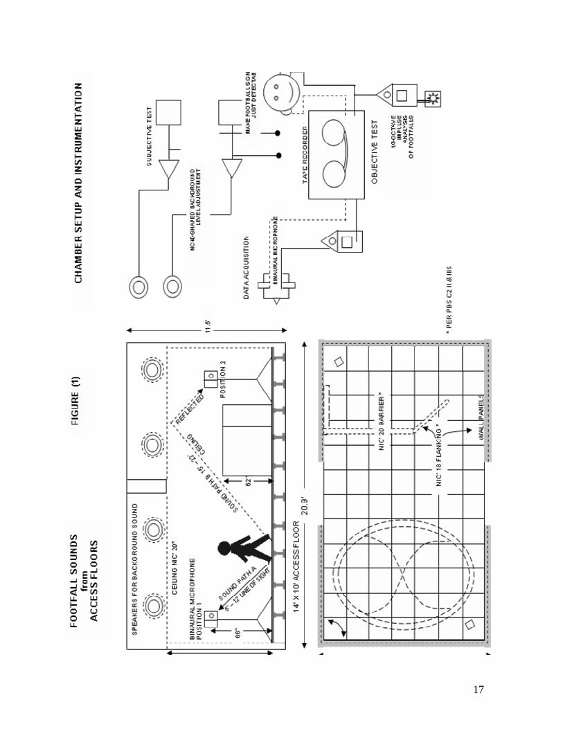
another. The design of the diffuser is also critical to minimizing transmission. The portion of the York MIT diffuser that is suspended below the raised floor is sealed on three sides, so that there is no direct path for sound to travel through one diffuser to another when the air input openings are facing opposite one another. Whenever possible, the diffuser’s air input openings should be facing away from each other in applications where room-to-room privacy is required. In test (C), with the diffuser air inputs facing towards each other, an NNIC rating of 44 was achieved for the system. This represents a “worst case” acoustical scenario for private offices that is probably avoidable in most cases. However, the NNIC 44 rating is still above the sound transmission performance of typical walls and suspended ceilings – STC-36 for non insulated drywall and STC-42 for insulated drywall and CAC of 35 to 40 for standard suspended lay-in ceilings. The positioning of diffuser air inputs in strictly open office applications is not an acoustical concern. In open office environments the amount of speech transmission through air diffusers would be miniscule compared to the speech diffraction over the furniture divider panels. Impact of Footfall Noise on Raised Floors: Preface We do not consider footfall noise with raised floors to be a significant interiors issue. The reality is that with todays high density of workstations (average 6’ x 8’ cubicles) there is ample speech noise in most facilities which pushes the building background sound level to the point where the presence of some footfall noise should not be problematic. Test Procedure and Floor Design The purpose of the test is to assess the acoustical intrusion of the sound of footfalls upon occupants of an open-office environment. It was conducted with female walkers in hard-heeled shoes. To simulate a raised floor system in an open-office environment, the sidewalls and suspended acoustical ceiling of the test chamber were treated with highly absorptive materials. A continuous six-inch high ConCore 1000 / PosiLock access floor system was erected on the chamber floor. The floor surface was covered with unadhered Interface Style 2400 18 x 18 carpet tiles. A background sound system was installed in the plenum space above the acoustical ceiling. To assess the acoustical intrusion of the sound of footfalls on office occupants, the level of impact noise was measured at two occupant locations relative to the source of the footfall sounds. The direct line of sight path was measured where the direct sound path between the listener (a microphone) and the walker’s shoes varied between 6 and 12 feet. The ceiling reflected path was measured where the sound path between the listener (again, a microphone) and the walker’s shoes varied between 15 and 22 feet – by way of a reflection from the acoustical ceiling. For this test, there was a 62-inch high barrier on the raised floor separating the walker from the microphone, which prevented direct passage of sound from the walker’s shoes to the microphone. In each case, the tester adjusted the level of background noise in the chamber as necessary to make the footfall sounds just detectable and noted the sound level. All adjustments in the background noise level masked the sounds of footfalls on the test floor. Test Results* The following background noise levels were required to mask the footfall sounds for the listener: Test (A) - Direct line of sight path: The level of background noise required to make the average footfall signal just detectable was NC-43. Test (B) - Ceiling reflected path: The level of background noise required to make the average footfall signal just detectable was NC-34. * Full Geiger and Hamme test report can be found on pages 16 - 18. See Test No. TA- 4MT. Conclusions It must first be noted that recommended NC ranges for open-office environments, reception areas, and cafeterias during working hours are typically within the range of NC-35 to NC-40; recommended ranges for
corridors and lobbies are typically from NC-40 to NC-45. Regarding the direct line of sight path test (Test A), where an NC-Level of 43 was required to mask the footfall sounds, keep in mind that the listening device was between 6 and 12 feet from the walker at all times. Footfall sounds generated at such a short distance from a listener will easily be detectable on any type of carpet covered floor in an office environment. In the case of the ceiling reflected path, (Test B), the NC-34 background noise level required to mask the footfall noise was just below the typical NC-35 to 40 range recommended for open-office environments. Significance of the NC-Level: Noise Criteria (NC) level is a standard that describes the constant, continuous background noise perceived inside of a space, examining a range of frequencies (rather than simply recording the decibel level). This level illustrates the extent to which noise interferes with speech intelligibility. NC is often considered for projects where excessive noise would be irritating to the users, especially where speech intelligibility is important.
7
GEIGER & HAMME, INC. Acoustical Testing
POST OFFICE BOX 1345 ANN ARBOR, MICHIGAN 48106
LABORATORIES: 3250 E. MORGAN RD.
REPORT
MOCK-UP TEST For
AIRBORNE SOUND TRANSMISSION
TO: TATE ACCESS FLOORS, INC. (formerly Tate Architectural Products, Inc.)
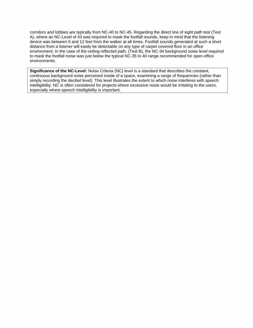
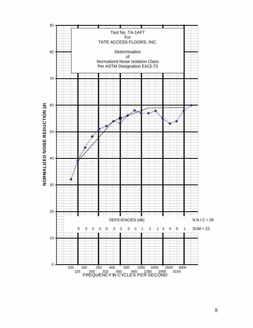
Jessup, Maryland Test No. TA-1AFT on samples received February 25, 1985 Specimen: One continuous 20’0” x 14’0” raised access floor system erected 6” above base concrete floor of 21’0” x 15’5” x 11’6” test chamber, with ancillary seals to chamber sidewalls. Floor comprised of seventy TATE Mod 924 ConCore G.C.S. panel units, each 24” x 24” x 1 ¼” – thick concrete filled steel panel corner-supported and bolted to a pedestal head of the TATE Understructure Cornerlock System Mod 912. Test chamber divided into two equal-size rooms by a 14’0” x 8’6” x 5 ½” – thick STC-54 partition installed in partition test opening with centerline over a line of floor panel joints, with a metal plenum divider installed in void space below floor specimen. Floor surface of both rooms covered with unadhered INTERFACE Style 2400 18” x 18” carpet tile. Floor plenum sidewalls lined with 4”-thick fiberglass to simulate conditions for a centrally-located expanse of floor. Weight of each floor panel with carpet tile: 38 lbs (9.5 psf). Floor of receiving room shielded with extra 5.5 psf floor covering verify flanking transmission of partition.
Octave-Interval Normalized Mid-Frequency Noise Reduction
(Hz) (dB)* fo .794fo fo 1.26fo
125 32. 39. 44. 250 48. 51. 52. 500 54. 53. 56. 1000 58. 57. 57. 2000 58. 55. 53. 4000 54. 58. 60.
Normalized Noise Isolation Class (NNIC)=55 per ASTM Designation E413-73
* Determined in accordance with ASTM Designation E336-77 as a mock-up measurement of
room-to-room noise reduction of a field condition wherein the transmission via paths other than the floor system is rendered negligible. Noise reductions are normalized to a receiving-room absorption condition of 0.5-second reverberation time.
For GEIGER & HAMME, INC. March 13, 1985
8
0
10
20
30
40
50
60
70
80
90
FREQUENCY IN CYCLES PER SECOND
NO
RM
ALI
ZED
NO
ISE
RE
DU
CTI
ON
(dB
Test No. TA-1AFT For
TATE ACCESS FLOORS, INC.
Determination of
Normalized Noise Isolation Class Per ASTM Designation E413-73
DEFICIENCIES (dB)
0 0 0 0 0 0 2 0 0 1 2 1 4 6 5 1
N N I C = 55 SUM = 22
100 160 250 400 630 1000 1600 2500 4000 125 200 315 500 800 1250 2000 3150
9
GEIGER & HAMME, INC. Acoustical Testing
POST OFFICE BOX 1345 ANN ARBOR, MICHIGAN 48106
LABORATORIES: 3250 E. MORGAN RD.
REPORT
MOCK-UP TEST For
AIRBORNE SOUND TRANSMISSION
TO: TATE ACCESS FLOORS, INC. (formerly Tate Architectural Products, Inc.)
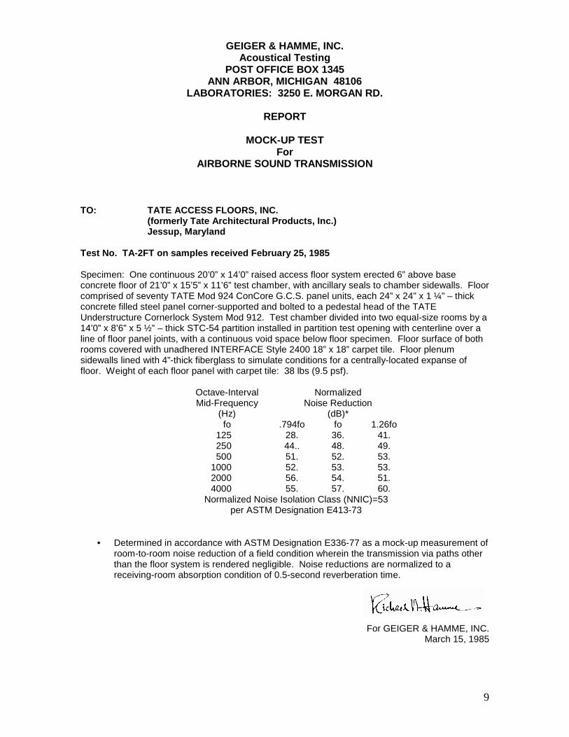
Jessup, Maryland Test No. TA-2FT on samples received February 25, 1985 Specimen: One continuous 20’0” x 14’0” raised access floor system erected 6” above base concrete floor of 21’0” x 15’5” x 11’6” test chamber, with ancillary seals to chamber sidewalls. Floor comprised of seventy TATE Mod 924 ConCore G.C.S. panel units, each 24” x 24” x 1 ¼” – thick concrete filled steel panel corner-supported and bolted to a pedestal head of the TATE Understructure Cornerlock System Mod 912. Test chamber divided into two equal-size rooms by a 14’0” x 8’6” x 5 ½” – thick STC-54 partition installed in partition test opening with centerline over a line of floor panel joints, with a continuous void space below floor specimen. Floor surface of both rooms covered with unadhered INTERFACE Style 2400 18” x 18” carpet tile. Floor plenum sidewalls lined with 4”-thick fiberglass to simulate conditions for a centrally-located expanse of floor. Weight of each floor panel with carpet tile: 38 lbs (9.5 psf).
Octave-Interval Normalized Mid-Frequency Noise Reduction
(Hz) (dB)* fo .794fo fo 1.26fo
125 28. 36. 41. 250 44.. 48. 49. 500 51. 52. 53. 1000 52. 53. 53. 2000 56. 54. 51. 4000 55. 57. 60.
Normalized Noise Isolation Class (NNIC)=53 per ASTM Designation E413-73
• Determined in accordance with ASTM Designation E336-77 as a mock-up measurement of room-to-room noise reduction of a field condition wherein the transmission via paths other than the floor system is rendered negligible. Noise reductions are normalized to a receiving-room absorption condition of 0.5-second reverberation time.
For GEIGER & HAMME, INC. March 15, 1985
10
0
10
20
30
40
50
60
70
80
90
FREQUENCY IN CYCLES PER SECOND
NO
RM
ALI
ZED
NO
ISE
RED
UC
TIO
N (d
B)
100 160 250 400 630 1000 1600 2500 4000 125 200 315 500 800 1250 2000 3150
Test No. TA-2FT For
TATE ACCESS FLOORS, INC.
Determination of
Normalized Noise Isolation Class Per ASTM Designation E413-73
DEFICIENCIES (dB)
1 0 0 0 0 1 1 1 3 3 4 1 3 6 2 0
N N I C = 53 SUM = 26

11
GEIGER & HAMME, INC. Acoustical Testing
POST OFFICE BOX 1345 ANN ARBOR, MICHIGAN 48106
LABORATORIES: 3250 E. MORGAN RD.
REPORT
MOCK-UP TEST For
AIRBORNE SOUND TRANSMISSION
TO: YORK INTERNATIONAL CORPORATION York, Pennsylvania Test No. YRKI-1FT on sample received May 5, 2000 Specimen: One continuous 20’0” x 14’0” raised access floor system erected 12” above base concrete floor of 21’0” x 15’5” x 11’6” test chamber, with ancillary seals to chamber sidewalls and floor. Floor system comprised of Interface 50cm x 50cm Carpet Tile with composition backing laid over 24” x 24” x 1 1/16” – thick concrete InterfaceAR Tec-Crete I Access Floor Panels supported engaged and bolted on embossed steel top plates on threaded post and jam nut pedestal assemblies. Test chamber divided into two equal-size rooms by a 14’ run of 6”-thick STC-58 partition installed in the partition test opening with the floor track sealed to the concrete surface of the floor panels bridging the partition, with a continuous void space below the floor specimen. Floor system penetrated by one York International Type MIT-C Diffuser Unit in each room located centered approximately 2’ from the partition on the chamber centerline. Diffuser units set with dampers fully open, with open sides oriented away from the partition with a 5’ separation. Floor erected with panel edges abutting without ancillary seals, with the floor plenum sidewalls lined with 4”-thick fiberglass to simulate conditions for a centrally-located expanse of floor. Weight of each floor panel: 41 lbs (10.25 PSF); of each carpet tile: 2.79 lbs (1.04 PSF).
Octave-Interval Normalized Mid-Frequency Noise Reduction
(Hz) (dB)* fo 2 -1/3fo fo 2 +1/3fo
125 24. 35. 39. 250 44.. 46. 43. 500 49. 50. 50. 1000 50. 48. 49. 2000 51. 55. 56. 4000 55. 58. 61.
Normalized Noise Isolation Class (NNIC)=51 per ASTM Designation E413-87
* Determined in accordance with ASTM Designation E336-77 as a mock-up measurement of
room-to-room noise reduction of a field condition wherein the transmission via paths other than the floor system is rendered negligible. Noise reductions are normalized to a receiving-room absorption condition of 0.5-second reverberation time.
* Normalized Noise Reduction and NNIC are to be identified with the corresponding quantities,
Normalized Ceiling Attenuation and CAC determined by ASTM Designation E1414.
for GEIGER & HAMME, L.L.C.
May 11, 2000

12
York International Corp. ASTM-E336 YRKI-1FT One York Diffuser Unit MIT-C in each of two rooms in carpeted Interface floor with 6” STC 58 wall.
DETERMINATION OF NNIC BY ASTM E413-87
05/12/2000 Geiger & Hamme L.L.C.
20
30
40
50
60
70
100 125 160 200 250 315 400 500 630 800 1000 1250 1600 2000 2500 3150 4000 5000
1/3 OCTAVE FREQUENCY (Hz)
TRA
NS
MIS
SIO
N LO
SS
(dB
)
Normalized Noise Reduction Between Rooms - NNICWithout Diffusers NNIC 52

13
NNIC=51
SUM=270 0 0 0 4 1 1 2 3 6 6 4 0 0 0 0
York International Corp. ASTM-E336 YRKI-1FT One York Diffuser Unit MIT-C in each of two rooms in carpeted Interface floor with 6” STC 58 wall.
DETERMINATION OF NNIC BY ASTM E413-87
05/12/2000 Geiger & Hamme L.L.C.
20
30
40
50
60
70
100 125 160 200 250 315 400 500 630 800 1000 1250 1600 2000 2500 3150 4000 5000
1/3 OCTAVE FREQUENCY (Hz)
TRA
NSM
ISSI
ON
LO
SS (d
B)
Normalized Noise Reduction Between Rooms - NNIC

14
Mark E. Schaffer ASTM-E336 FLOOR TESTS One York Diffuser Unit MIT-C in each of two rooms in carpeted Interface floor with 6” STC 58 wall.
DETERMINATION OF NNIC BY ASTM E413-87
05/12/2000 Geiger & Hamme L.L.C.
20
30
40
50
60
70
100 125 160 200 250 315 400 500 630 800 1000 1250 1600 2000 2500 3150 4000 5000
1/3 OCTAVE FREQUENCY (Hz)
TRA
NSM
ISSI
ON
LO
SS (d
B)
B-Diffuser input facing NNIC44 A-Diffuser input looking away NNIC51Without Diffusers NNIC 52
A
38”
B
B
A
15
GEIGER & HAMME, INC. Acoustical Testing
POST OFFICE BOX 1345 ANN ARBOR, MICHIGAN 48106
LABORATORIES: 3250 E. MORGAN RD.
REPORT
FOOTFALL SOUNDS from
ACCESS FLOORS
TO: TATE ACCESS FLOORS, INC. (formerly Tate Architectural Products, Inc.)
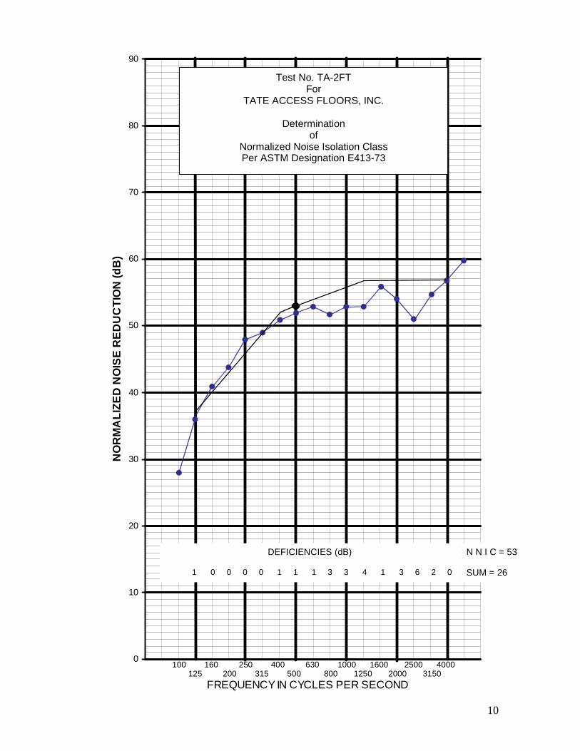
Jessup, Maryland Test No. TA-4MT on samples received February 25, 1985 Specimen: One continuous 20’0” x 14’0” raised access floor system erected 6” above base concrete floor of 21’0” x 15’5” x 11’6” test chamber, with ancillary seals to chamber sidewalls. Floor comprised of seventy TATE Mod 924 ConCore G.C.S. panel units, each 24” x 24” x 1 ¼” – thick concrete filled steel panel corner-supported and bolted to a pedestal head of the TATE Understructure Cornerlock System Mod 912 after pedestals were releveled. A 15’ x 20’ suspended acoustical ceiling (NIC’>20) is installed 8’6” above the floor surface which is covered with unadhered INTERFACE Style 2400 18” x 18” carpet tile. Floor plenum sidewalls lined with 4”-thick fiberglass to simulate conditions for a centrally-located expanse of floor. Weight of each floor panel with carpet tile: 38 lbs (0.5 psf).
Octave-Interval 1/3 Octave Footfall Level (dB)* Mid-Frequency Sound Path A Sound Path B
(Hz) Direct Line of Sight Ceiling Reflected 6’-12’ 15’-22’
fo .794fo Fo 1.26fo .794fo fo 1.26fo
125 53. 42. 36. 45. 33. 31. 250 36. 33. 31. 31. 28. 26. 500 30. 31. 29. 23. 22. 20.
1000 32. 33. 34. 21. 23. 23. 2000 34. 33. 30. 24. 22. 19. 4000 27. 25. 23. 19. 18. 19.
NC40 Masking Level** +3 = NC43 -6 = NC34 * Determined in accordance with Insulation Board Institute Test IBI-1-I 1965 and ASTM
STANDARDS Part 18 pg. 1172-1179 1978 for measurement of sound produced by female walkers wearing hard-heeled shoes and traversing a prescribed path at her normal walking gait. Test method modified to measure re-radiated footfall sounds from the impacted surface of floor system as averaged for two walkers.
* Level of NC40-shaped background noise required to make average footfall signal just
detectable.
For GEIGER & HAMME, INC. April 4, 1985

16
17