
RAIO-01 Analogue I/O Extension User's Manual ... - ABB Ltd · the RAIO-01 Analogue I/O Extension...
28
ABB Drives Analogue I/O Extension Module RAIO-01 User’s Manual
Transcript of RAIO-01 Analogue I/O Extension User's Manual ... - ABB Ltd · the RAIO-01 Analogue I/O Extension...
ABB Drives
Analogue I/O Extension ModuleRAIO-01
User’s Manual

©
Analogue I/O Extension ModuleRAIO-01
User’s Manual
3AFE64484567 REV B EN
EFFECTIVE: 2009-04-21
2009 ABB Oy. All Rights Reserved.


Safety instructions
Overview This chapter states the general safety instructions that must be followed when installing and operating the RAIO-01 Analogue I/O Extension module.
The material in this chapter must be studied before attempting any work on, or with, the unit.
In addition to the safety instructions given below, read the complete safety instructions of the specific drive you are working on.
General safety instructions
WARNING! All electrical installation and maintenance work on the drive should be carried out by qualified electricians only.
The drive and adjoining equipment must be properly earthed.
Do not attempt any work on a powered drive. After switching off the mains, always allow the intermediate circuit capacitors 5 minutes to discharge before working on the frequency converter, the motor or the motor cable. It is good practice to check (with a voltage indicating instrument) that the drive is in fact discharged before beginning work.
The motor cable terminals of the drive are at a dangerously high voltage when mains power is applied, regardless of motor operation.
There can be dangerous voltages inside the drive from external control circuits even when the drive mains power is shut off. Exercise appropriate care when working on the unit. Neglecting these instructions can cause physical injury or death.
RAIO-01 User’s manual 5
Safety instructions
6 RAIO-01 User’s manual
Table of contents
Safety instructionsOverview . . . . . . . . . . . . . . . . . . . . . . . . . . . . . . . . . . . . . . . . . . . . . . . . . . . . . 5General safety instructions. . . . . . . . . . . . . . . . . . . . . . . . . . . . . . . . . . . . . . . . 5
Table of contents
Chapter 1 – IntroductionIntended audience . . . . . . . . . . . . . . . . . . . . . . . . . . . . . . . . . . . . . . . . . . . . . . 9Before you start . . . . . . . . . . . . . . . . . . . . . . . . . . . . . . . . . . . . . . . . . . . . . . . . 9What this manual contains . . . . . . . . . . . . . . . . . . . . . . . . . . . . . . . . . . . . . . . 10
Chapter 2 – OverviewOverview . . . . . . . . . . . . . . . . . . . . . . . . . . . . . . . . . . . . . . . . . . . . . . . . . . . . 11The RAIO-01 module . . . . . . . . . . . . . . . . . . . . . . . . . . . . . . . . . . . . . . . . . . . 11
Module layout . . . . . . . . . . . . . . . . . . . . . . . . . . . . . . . . . . . . . . . . . . . . . . . 11Delivery check . . . . . . . . . . . . . . . . . . . . . . . . . . . . . . . . . . . . . . . . . . . . . . 12Compatibility . . . . . . . . . . . . . . . . . . . . . . . . . . . . . . . . . . . . . . . . . . . . . . . . 12Warranty and liability information . . . . . . . . . . . . . . . . . . . . . . . . . . . . . . . . 12
Chapter 3 – InstallationMounting . . . . . . . . . . . . . . . . . . . . . . . . . . . . . . . . . . . . . . . . . . . . . . . . . . . . 13
Mounting onto RMIO board . . . . . . . . . . . . . . . . . . . . . . . . . . . . . . . . . . . . 13Mounting onto AIMA adapter . . . . . . . . . . . . . . . . . . . . . . . . . . . . . . . . . . . 14
Removing and refitting the cover of the enclosure . . . . . . . . . . . . . . . . . . . . . 15Switches. . . . . . . . . . . . . . . . . . . . . . . . . . . . . . . . . . . . . . . . . . . . . . . . . . . . . 15Input mode selection . . . . . . . . . . . . . . . . . . . . . . . . . . . . . . . . . . . . . . . . . . . 16Input signal type selection . . . . . . . . . . . . . . . . . . . . . . . . . . . . . . . . . . . . . . . 17Terminal designations . . . . . . . . . . . . . . . . . . . . . . . . . . . . . . . . . . . . . . . . . . 18Wiring . . . . . . . . . . . . . . . . . . . . . . . . . . . . . . . . . . . . . . . . . . . . . . . . . . . . . . . 19Node ID selection. . . . . . . . . . . . . . . . . . . . . . . . . . . . . . . . . . . . . . . . . . . . . . 20Programming . . . . . . . . . . . . . . . . . . . . . . . . . . . . . . . . . . . . . . . . . . . . . . . . . 20
RAIO-01 User’s manual 7

Table of contents
Chapter 4 – Fault tracingStatus LED . . . . . . . . . . . . . . . . . . . . . . . . . . . . . . . . . . . . . . . . . . . . . . . . . . .21
Option slot installation . . . . . . . . . . . . . . . . . . . . . . . . . . . . . . . . . . . . . . .21AIMA-01 I/O Module Adapter installation . . . . . . . . . . . . . . . . . . . . . . . .21
Appendix A – Technical data
8 RAIO-01 User’s manual

Chapter 1 – Introduction
Intended audience
The manual is intended for the people who are responsible for commissioning and using an RAIO-01 Analogue I/O Extension module with the ACS800 drive. The reader is expected to have a basic knowledge of electrical fundamentals, electrical wiring practices and how to operate the drive.
Before you start It is assumed that the drive is installed and ready to operate before starting the installation of the extension module.
In addition to conventional installation tools, have the drive manuals available during the installation as they contain important information not included in this manual. The drive manuals are referred to at various points of this document.
RAIO-01 User’s manual 9
Chapter 1 – Introduction
What this manual contains
This manual contains information on the wiring, configuration and use of the RAIO-01 module.
Safety instructions are featured in the first few pages of this manual.
Chapter 2 – Overview contains a short description of the RAIO-01 Analogue I/O Extension module, a delivery checklist and warranty information.
Chapter 3 – Installation contains instructions for module hardware settings, mounting and cabling.
Chapter 4 – Fault tracing explains fault tracing and the LED indications of the RAIO-01 module.
Appendix A contains technical data.
10 RAIO-01 User’s manual
Chapter 2 – Overview
Overview This chapter contains a short description of the Analogue I/O Extension module, a delivery checklist and warranty information.
The RAIO-01 module
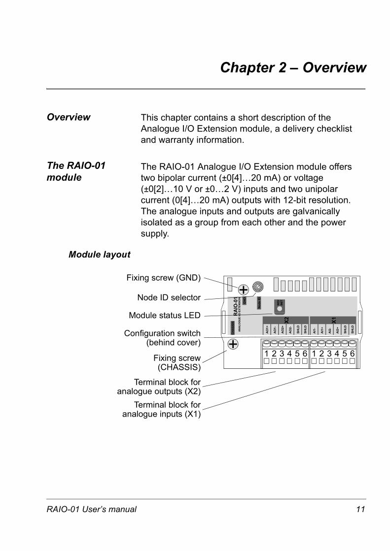
The RAIO-01 Analogue I/O Extension module offers two bipolar current (±0[4]…20 mA) or voltage (±0[2]…10 V or ±0…2 V) inputs and two unipolar current (0[4]…20 mA) outputs with 12-bit resolution. The analogue inputs and outputs are galvanically isolated as a group from each other and the power supply.
Module layout
1 2 3 4 5 6 1 2 3 4 5 6
Fixing screw (GND)
Node ID selector
Module status LED
Fixing screw (CHASSIS)
Configuration switch (behind cover)
0 8
4
C
2 6
AE
1
3 5
79
BD
F
CH
ASS
IS
GN
D
Nod
e ID
AO
1+
SHLD
SHLD
AO
1-
AO
2+
AO
2-
AI1
-
SHLD
SHLD
AI1
+
AI2
-
AI2
+
WD
/IN
IT
RAIO
-01
ANAL
OG
UE
I/O E
XTEN
SIO
N
X2 X1
Terminal block for analogue outputs (X2)
Terminal block for analogue inputs (X1)
RAIO-01 User’s manual 11
Chapter 2 – Overview
Delivery check The option package contains:
• RAIO-01 module
• Two screws
• This manual.
Compatibility The RAIO-01 is compatible with the ACS800 Standard Application Program version ASXR7000 or later.
Warranty and liability
information
The warranty for your ABB drive and options covers manufacturing defects. The manufacturer carries no responsibility for damage due to transport or unpacking.
In no event and under no circumstances shall the manufacturer be liable for damages and failures due to misuse, abuse, improper installation, or abnormal conditions of temperature, dust, or corrosives, or failures due to operation above rated capacities. Nor shall the manufacturer ever be liable for consequential and incidental damages.
The period of manufacturer's warranty is 12 months, and not more than 18 months, from the date of delivery. Extended warranty may be available with certified start-up. Contact your local distributor for details.
Your local ABB Drives company or distributor may have a different warranty period, which is specified in their sales terms, conditions, and warranty terms.
If you have any questions concerning your ABB drive, contact your local distributor or ABB Drives office.
The technical data and specifications are valid at the time of printing. ABB reserves the right to subsequent alterations.
12 RAIO-01 User’s manual
Chapter 3 – Installation
WARNING! Follow the safety instructions given in this guide and in the Hardware Manual of the drive.
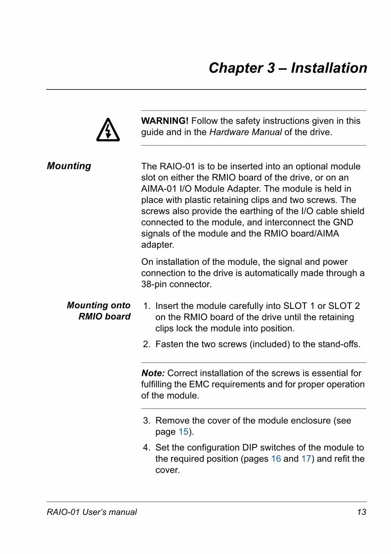
Mounting The RAIO-01 is to be inserted into an optional module slot on either the RMIO board of the drive, or on an AIMA-01 I/O Module Adapter. The module is held in place with plastic retaining clips and two screws. The screws also provide the earthing of the I/O cable shield connected to the module, and interconnect the GND signals of the module and the RMIO board/AIMA adapter.
On installation of the module, the signal and power connection to the drive is automatically made through a 38-pin connector.
Mounting onto RMIO board
1. Insert the module carefully into SLOT 1 or SLOT 2 on the RMIO board of the drive until the retaining clips lock the module into position.
2. Fasten the two screws (included) to the stand-offs.
Note: Correct installation of the screws is essential for fulfilling the EMC requirements and for proper operation of the module.
3. Remove the cover of the module enclosure (see page 15).
4. Set the configuration DIP switches of the module to the required position (pages 16 and 17) and refit the cover.
RAIO-01 User’s manual 13
Chapter 3 – Installation
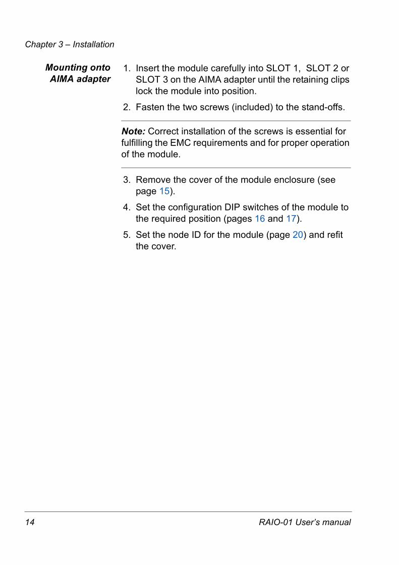
Mounting onto AIMA adapter
1. Insert the module carefully into SLOT 1, SLOT 2 or SLOT 3 on the AIMA adapter until the retaining clips lock the module into position.
2. Fasten the two screws (included) to the stand-offs.
Note: Correct installation of the screws is essential for fulfilling the EMC requirements and for proper operation of the module.
3. Remove the cover of the module enclosure (see page 15).
4. Set the configuration DIP switches of the module to the required position (pages 16 and 17).
5. Set the node ID for the module (page 20) and refit the cover.
14 RAIO-01 User’s manual
Chapter 3 – Installation
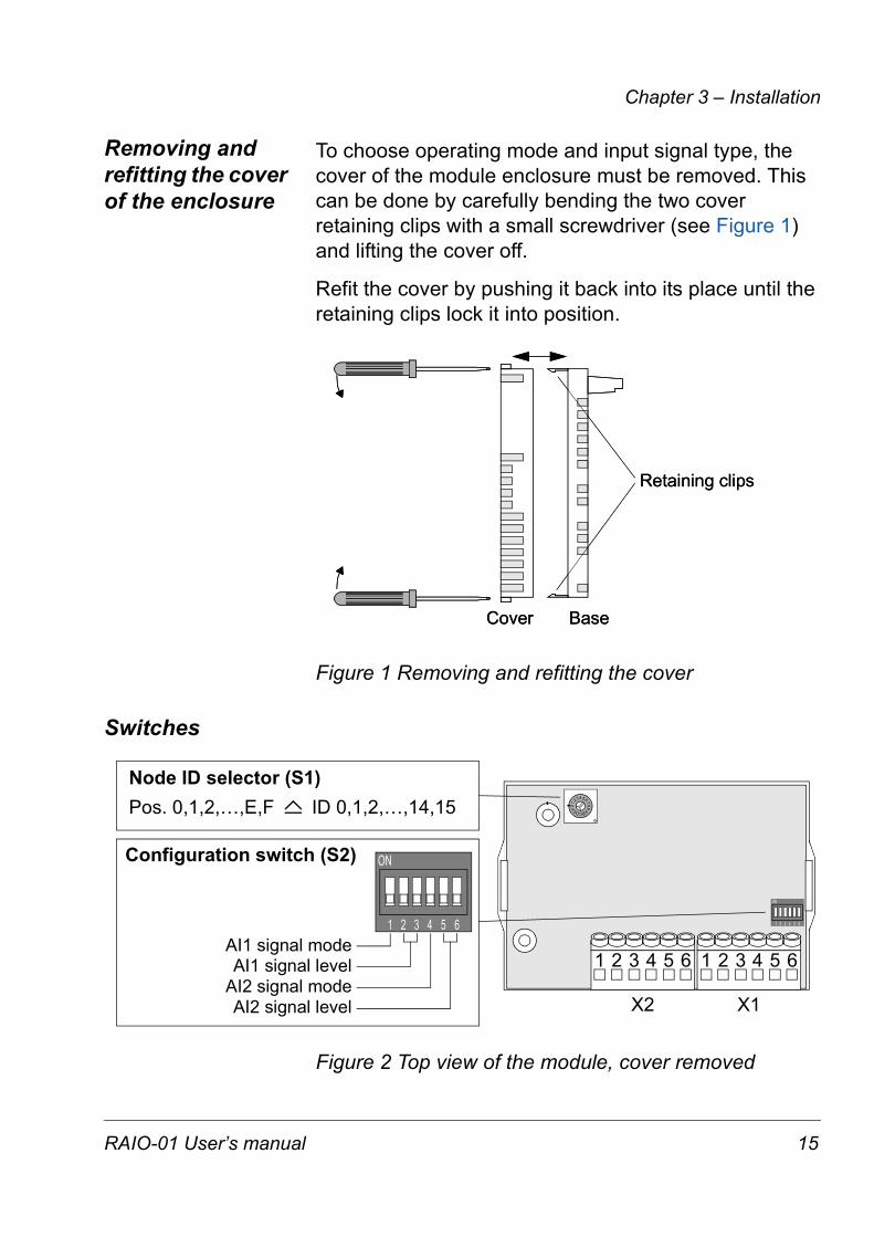
Removing and refitting the cover of the enclosure
To choose operating mode and input signal type, the cover of the module enclosure must be removed. This can be done by carefully bending the two cover retaining clips with a small screwdriver (see Figure 1) and lifting the cover off.
Refit the cover by pushing it back into its place until the retaining clips lock it into position.
Figure 1 Removing and refitting the cover
Switches
Figure 2 Top view of the module, cover removed
Cover
Retaining clips
BaseCover
Retaining clips
Base
X2 X1
1 2 3 4 5 6 1 2 3 4 5 6
0 8
4
C
2 6
AE
1
3 5
79
BD
F
ON
1 2 3 4 5 6
ON
1 2 3 4 5 6AI1 signal modeAI1 signal level
AI2 signal modeAI2 signal level
Node ID selector (S1)Pos. 0,1,2,…,E,F ID 0,1,2,…,14,15
Configuration switch (S2)
RAIO-01 User’s manual 15

Chapter 3 – Installation
Input mode selection
The operating mode of the analogue inputs can be selected using the configuration DIP switch (S2) on the circuit board of the module. The drive parameters must be set accordingly.
In bipolar mode, the analogue inputs can handle positive and negative signals. The resolution of the A/D conversion is 11 data bits (+ 1 sign bit). The way the drive interprets the negative range of the inputs depends on the settings of the drive. See the Firmware Manual of the drive.
In unipolar mode (default), the analogue inputs can handle positive signals only. The resolution of the A/D conversion is 12 data bits.
DIP switch settingInput signal type
Analogue input AI1 Analogue input AI2
±0(4)…20 mA±0(2)…10 V
±0…2 V
0(4)…20 mA0(2)…10 V
0…2 V(Default)
ON
1 2 3 4 5 6
ON
1 2 3 4 5 6
ON
1 2 3 4 5 6
ON
1 2 3 4 5 6
16 RAIO-01 User’s manual
Chapter 3 – Installation
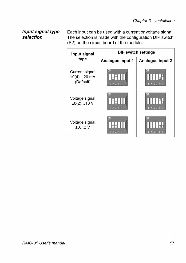
Input signal type selection
Each input can be used with a current or voltage signal. The selection is made with the configuration DIP switch (S2) on the circuit board of the module.
Input signal type
DIP switch settings
Analogue input 1 Analogue input 2
Current signal±0(4)…20 mA
(Default)
Voltage signal±0(2)…10 V
Voltage signal±0…2 V
ON
1 2 3 4 5 6
ON
1 2 3 4 5 6
ON
1 2 3 4 5 6
ON
1 2 3 4 5 6
ON
1 2 3 4 5 6
ON
1 2 3 4 5 6
RAIO-01 User’s manual 17
Chapter 3 – Installation
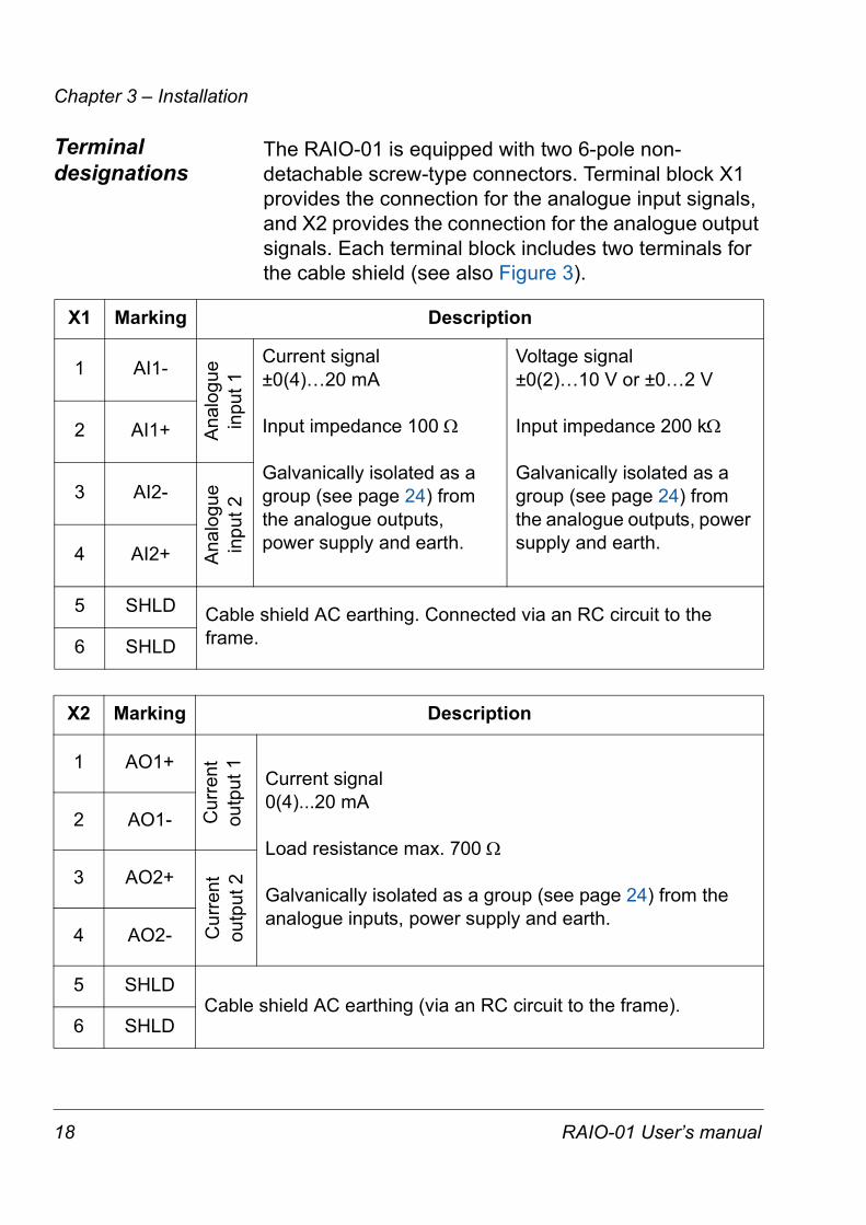
Terminal designations
The RAIO-01 is equipped with two 6-pole non-detachable screw-type connectors. Terminal block X1 provides the connection for the analogue input signals, and X2 provides the connection for the analogue output signals. Each terminal block includes two terminals for the cable shield (see also Figure 3).
X1 Marking Description
1 AI1-
Ana
logu
ein
put 1
Current signal±0(4)…20 mA
Input impedance 100 Ω
Galvanically isolated as a group (see page 24) from the analogue outputs, power supply and earth.
Voltage signal±0(2)…10 V or ±0…2 V
Input impedance 200 kΩ
Galvanically isolated as a group (see page 24) from the analogue outputs, power supply and earth.
2 AI1+
3 AI2-
Ana
logu
ein
put 2
4 AI2+
5 SHLD Cable shield AC earthing. Connected via an RC circuit to the frame.6 SHLD
X2 Marking Description
1 AO1+
Cur
rent
outp
ut 1 Current signal
0(4)...20 mA
Load resistance max. 700 Ω
Galvanically isolated as a group (see page 24) from the analogue inputs, power supply and earth.
2 AO1-
3 AO2+
Cur
rent
outp
ut 2
4 AO2-
5 SHLDCable shield AC earthing (via an RC circuit to the frame).
6 SHLD
18 RAIO-01 User’s manual
Chapter 3 – Installation
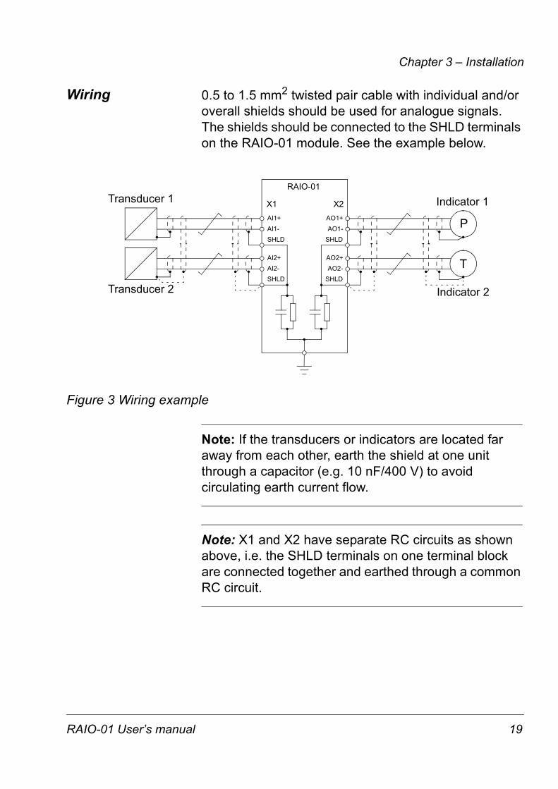
Wiring 0.5 to 1.5 mm2 twisted pair cable with individual and/or overall shields should be used for analogue signals. The shields should be connected to the SHLD terminals on the RAIO-01 module. See the example below.
Figure 3 Wiring example
Note: If the transducers or indicators are located far away from each other, earth the shield at one unit through a capacitor (e.g. 10 nF/400 V) to avoid circulating earth current flow.
Note: X1 and X2 have separate RC circuits as shown above, i.e. the SHLD terminals on one terminal block are connected together and earthed through a common RC circuit.
AI1+AI1-SHLD
Transducer 1
AI2+AI2-SHLD
Transducer 2
Indicator 1
Indicator 2
TSHLDAO2-AO2+
SHLDAO1-AO1+
RAIO-01
P
X2X1
RAIO-01 User’s manual 19

Chapter 3 – Installation
Node ID selection If the RAIO-01 module is mounted onto an external AIMA-01 I/O Module Adapter, choose the proper node ID for the module using the node ID selector (S1, range 1…15). Setting the node ID is not required when the module is mounted into SLOT 1 or SLOT 2 on the drive.
The default setting of selector S1 is 5.
Programming The communication between the module and the drive is activated by a drive parameter. (Ensure that the parameter settings correspond to the mode switch setting of the module.) The RAIO-01 can replace and/or extend certain standard inputs and outputs. See the drive Firmware Manual, Parameter Group 98.
Note: The new settings take effect only when the module is powered up.
20 RAIO-01 User’s manual

Chapter 4 – Fault tracing
Status LED There is one status LED (WD/INIT, yellow) on the RAIO-01 module. The LED is lit when the drive is configuring the module at power-up.
Option slot installation
In case the LED does not go out after one second:
• The configuration has failed.
- Cycle the power supply of the drive.
• The module has a hardware failure.
- Ensure the 38-pin connector is properly inserted.
- Contact an ABB service representative.
AIMA-01 I/O Module Adapter installation
• There is no communication with the drive.
- Check that the drive is powered.
- Check the module node ID.
- Check that the fibre optic cables are connected correctly (transmitters to receivers) and the connectors properly inserted.
- Check the fibre optic cables visually for dirt or flaws.
- Ensure the 38-pin connector is properly inserted.
- Try new fibre optic cables.
- Contact an ABB service representative.
RAIO-01 User’s manual 21
Chapter 4 – Fault tracing
22 RAIO-01 User’s manual
Appendix A – Technical data
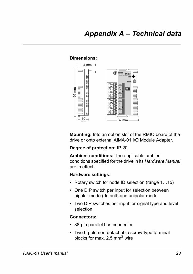
Dimensions:
Mounting: Into an option slot of the RMIO board of the drive or onto external AIMA-01 I/O Module Adapter.
Degree of protection: IP 20
Ambient conditions: The applicable ambient conditions specified for the drive in its Hardware Manual are in effect.
Hardware settings: • Rotary switch for node ID selection (range 1…15)
• One DIP switch per input for selection between bipolar mode (default) and unipolar mode
• Two DIP switches per input for signal type and level selection
Connectors:• 38-pin parallel bus connector
• Two 6-pole non-detachable screw-type terminal blocks for max. 2.5 mm2 wire
95 m
m
34 mm
20mm 62 mm
S2
12
34
56
12
34
56
0
8
4C
2
6A
E 1 35
79BD
F
CHASSIS
GND
Node ID
AO1+
SHLD
SHLD
AO1-
AO2+
AO2-
AI1-
SHLD
SHLD
AI1+
AI2-
AI2+
WD/INIT
RAIO-01ANALOGUE I/O EXTENSION
X2
X1
RAIO-01 User’s manual 23
Appendix A – Technical data
Analogue inputs:
• Signal types: ±(0)4…20 mA, ±(0)2…10 V, ±0…2 V
• Input impedance: 100 Ω (current), 200 kΩ (voltage)
• Resolution in unipolar mode: 0.024% (12 data bits)
• Resolution in bipolar mode: 0.048% (11 data bits + sign)
• Inaccuracy: ±0.5% (Full Scale Range) at 25 °C Temperature coefficient: ±100 ppm/°C max.
• Isolated from the analogue outputs and the module carrier board. The maximum continuous isolation voltage is 48 V rms; the maximum peak value is 100 V. The isolation towards the chassis potential (e.g. GND and +24 VDC of the module carrier board) has been tested at 1.5 kV AC for 1 s.
• Common mode voltage: ±15 V max.
• HW filtering: 2 ms approx.
Analogue outputs:
• Signal type: 0(4)...20 mA
• Load resistance max.: 700 Ω
• Resolution: 0.024% (12 bits)
• Inaccuracy: ±0.5% (Full Scale Range) at 25 °C Temperature coefficient: ±100 ppm/°C max.
• Isolated from the analogue inputs and the module carrier board. The maximum continuous isolation voltage is 48 V rms; the maximum peak value is 100 V. The isolation towards the chassis potential (e.g. GND and +24 VDC of the module carrier board) has been tested at 1.5 kV AC for 1 s.
24 RAIO-01 User’s manual
Appendix A – Technical data
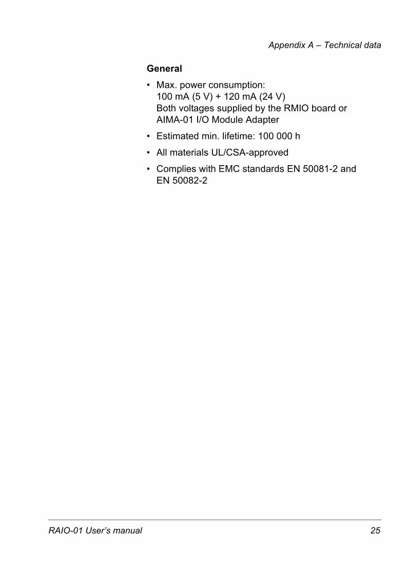
General• Max. power consumption:
100 mA (5 V) + 120 mA (24 V) Both voltages supplied by the RMIO board or AIMA-01 I/O Module Adapter
• Estimated min. lifetime: 100 000 h
• All materials UL/CSA-approved
• Complies with EMC standards EN 50081-2 and EN 50082-2
RAIO-01 User’s manual 25

Appendix A – Technical data
26 RAIO-01 User’s manual

ABB Oy AC Drives P.O. Box 184 FIN-00381 Helsinki FINLAND Telephone:+358 10 22 11
RA
IO-0
1 3A
FE64
4845
67 R
EV
B E
N
EFFE
CTI
VE:
200
9-04
-21
ABB Inc. Drives & Power Products 16250 West Glendale Drive New Berlin, WI 53151 USA Telephone:262 785-8378
Fax: +358 10 222 2681 Internet: www.abb.com
800 243-4384 Fax: 262 780-5135