Raindrops push and splash flying insects - UCF...
16
PHYSICS OF FLUIDS 26, 027104 (2014) Raindrops push and splash flying insects Andrew K. Dickerson, 1 Peter G. Shankles, 1 and David L. Hu 2, a) 1 School of Mechanical Engineering, Georgia Institute of Technology, Atlanta, Georgia 30332, USA 2 Schools of Mechanical Engineering, Biology, and Physics, Georgia Institute of Technology, Atlanta, Georgia 30332, USA (Received 3 May 2013; accepted 13 January 2014; published online 21 February 2014) In their daily lives, flying insects face a gauntlet of environmental challenges, from wind gusts to raindrop impacts. In this combined experimental and theoretical study, we use high-speed videography to film raindrop collisions upon both flying insects and dynamically scaled spherical mimics. We identify three outcomes of the collision based upon the insect’s mass and characteristic size: drops push the insect while remaining intact, coat the insect, and splash. We present a mathematical model that predicts impact force and outcome consistent with those found in experiments. Small insects such as gnats and flies are pushed by raindrops that remain intact upon impact; conversely, large flyers such as locusts and micro-aerial vehicles cause drops to splash. We identify a critical mass of 0.3 g for which flyers achieve both peak acceleration (100 g) and applied force (10 4 dyn) from incoming raindrops; designs of similarly massed flying robots should be avoided. C 2014 AIP Publishing LLC. [http://dx.doi.org/10.1063/1.4865819] I. INTRODUCTION New manufacturing techniques have unleashed an array of insect-sized flying robots, also known as micro-aerial vehicles (MAVs), envisioned for use in surveillance and reconnaissance. 1–4 Although MAVs are to be deployed outdoors, studies are generally conducted in still air rather than the complex conditions presented in nature. How can MAVs be designed to withstand in-flight perturbations from wind gusts and rain? Answering this question will help us design more robust flying robots. Inspiration for robust and efficient flight is readily found in nature. For millions of years, flying insects have been challenged by in-flight collision with falling drops (Fig. 1). Rain of various intensity, dripping from overhanging leaves, and splashes from cascades all generate drops that may strike an insect mid-flight. 5, 6 A raindrop, 7 like that depicted in Fig. 2, can have a mass m 1 = 4−100 mg, radius R 1 = 1−4 mm, and speed u 1 up to 10 m/s. Their shapes can vary from a sphere for small drops, to flattened shapes for large drops. Previous studies of flight in rain focus on vertebrate flyers such as bats and birds, whose mass is much larger than raindrops. Flying bats exhibit higher metabolic consumption when flying in rain, mainly due to their additional wet mass. 8 Hummingbirds fly in rain to feed, and can shake off accumulated water mid-flight to reduce the cost of carrying wet feathers. 9 These animals are so large they suffer multiple raindrops in a single wingbeat. Such studies are likely not applicable to understanding how an insect flies in the rain because of the insect’s much smaller size compared to vertebrate flyers. Most flying insects are so small that falling rain appears as discrete in-flight perturbations. The mechanics of this impact is complex, and has only been studied in detail in the limit of small insect size. In 2012, Dickerson et al. 10 showed a mosquito can survive impact with a raindrop of 50 times greater mass. The mosquito’s low mass decreases its impact force by a factor of 10 2 relative to a) Author to whom correspondence should be addressed. Electronic mail: [email protected] 1070-6631/2014/26(2)/027104/16/$30.00 C 2014 AIP Publishing LLC 26, 027104-1
Transcript of Raindrops push and splash flying insects - UCF...
PHYSICS OF FLUIDS 26, 027104 (2014)
Raindrops push and splash flying insectsAndrew K. Dickerson,1 Peter G. Shankles,1 and David L. Hu2,a)
1School of Mechanical Engineering, Georgia Institute of Technology, Atlanta, Georgia30332, USA2Schools of Mechanical Engineering, Biology, and Physics, Georgia Instituteof Technology, Atlanta, Georgia 30332, USA
(Received 3 May 2013; accepted 13 January 2014; published online 21 February 2014)
In their daily lives, flying insects face a gauntlet of environmental challenges, fromwind gusts to raindrop impacts. In this combined experimental and theoretical study,we use high-speed videography to film raindrop collisions upon both flying insectsand dynamically scaled spherical mimics. We identify three outcomes of the collisionbased upon the insect’s mass and characteristic size: drops push the insect whileremaining intact, coat the insect, and splash. We present a mathematical model thatpredicts impact force and outcome consistent with those found in experiments. Smallinsects such as gnats and flies are pushed by raindrops that remain intact uponimpact; conversely, large flyers such as locusts and micro-aerial vehicles cause dropsto splash. We identify a critical mass of 0.3 g for which flyers achieve both peakacceleration (100 g) and applied force (104 dyn) from incoming raindrops; designsof similarly massed flying robots should be avoided. C© 2014 AIP Publishing LLC.[http://dx.doi.org/10.1063/1.4865819]
I. INTRODUCTION
New manufacturing techniques have unleashed an array of insect-sized flying robots, also knownas micro-aerial vehicles (MAVs), envisioned for use in surveillance and reconnaissance.1–4 AlthoughMAVs are to be deployed outdoors, studies are generally conducted in still air rather than the complexconditions presented in nature. How can MAVs be designed to withstand in-flight perturbations fromwind gusts and rain? Answering this question will help us design more robust flying robots.
Inspiration for robust and efficient flight is readily found in nature. For millions of years,flying insects have been challenged by in-flight collision with falling drops (Fig. 1). Rain of variousintensity, dripping from overhanging leaves, and splashes from cascades all generate drops that maystrike an insect mid-flight.5, 6 A raindrop,7 like that depicted in Fig. 2, can have a mass m1 = 4−100mg, radius R1 = 1−4 mm, and speed u1 up to 10 m/s. Their shapes can vary from a sphere for smalldrops, to flattened shapes for large drops.
Previous studies of flight in rain focus on vertebrate flyers such as bats and birds, whose massis much larger than raindrops. Flying bats exhibit higher metabolic consumption when flying inrain, mainly due to their additional wet mass.8 Hummingbirds fly in rain to feed, and can shakeoff accumulated water mid-flight to reduce the cost of carrying wet feathers.9 These animals are solarge they suffer multiple raindrops in a single wingbeat. Such studies are likely not applicable tounderstanding how an insect flies in the rain because of the insect’s much smaller size compared tovertebrate flyers.
Most flying insects are so small that falling rain appears as discrete in-flight perturbations. Themechanics of this impact is complex, and has only been studied in detail in the limit of small insectsize. In 2012, Dickerson et al.10 showed a mosquito can survive impact with a raindrop of 50 timesgreater mass. The mosquito’s low mass decreases its impact force by a factor of 102 relative to
a)Author to whom correspondence should be addressed. Electronic mail: [email protected]
1070-6631/2014/26(2)/027104/16/$30.00 C©2014 AIP Publishing LLC26, 027104-1
027104-2 Dickerson, Shankles, and Hu Phys. Fluids 26, 027104 (2014)
(a)
(b)
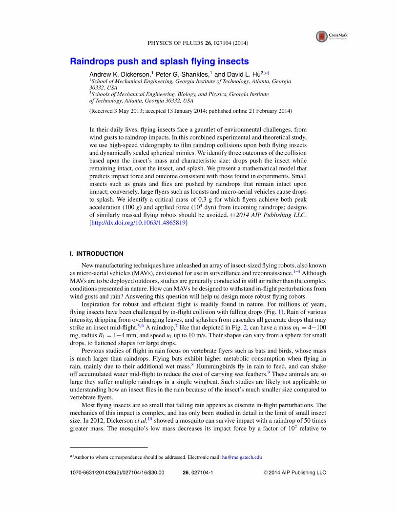
FIG. 1. Raindrop impacts upon (a) a house fly, recently deceased and standing on the ground, and (b) a live mosquito fixedto the ground.
impact on a mosquito resting on a branch.10 This study investigates how more massive insects, froma 1 mg mosquito to a 1 g dragonfly, survive impact.
Fig. 3 shows the relation between non-dimensional mass m2/m1 and effective radius R2/R1,where R2 is taken to be half the wingspan, of 21 insects from literature.11–21 We find insect wingspanscales with mass as W ∼ m0.44
2 (R2 = 0.91), where mass spans 1–1200 mg and wingspan W spans2–50 mm. In this study, we build insect mimics within this range to investigate how the size ofinsects affects drop collisions.
Nearly all flying insects are adapted for contact with water. Insect wings are covered with micro-and nano-scale structures which enhance hydrophobicity, enabling the wings to be cleaned moreeasily.22 Butterfly wings, in particular, have directional adhesion which aids in shedding drops.23
The adaptations of these animals suggest a primal relationship between insects and rainfall.
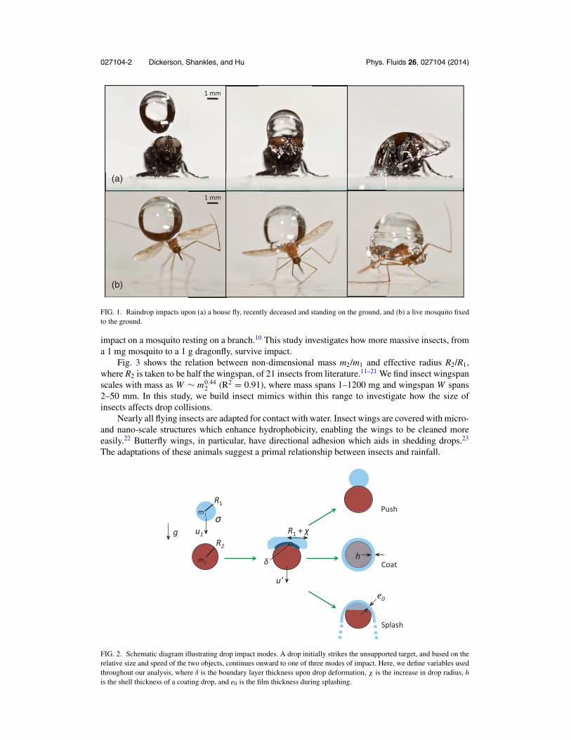
FIG. 2. Schematic diagram illustrating drop impact modes. A drop initially strikes the unsupported target, and based on therelative size and speed of the two objects, continues onward to one of three modes of impact. Here, we define variables usedthroughout our analysis, where δ is the boundary layer thickness upon drop deformation, χ is the increase in drop radius, his the shell thickness of a coating drop, and e0 is the film thickness during splashing.

027104-3 Dickerson, Shankles, and Hu Phys. Fluids 26, 027104 (2014)
FIG. 3. The relation between radius ration R2/R1 and mass ratio m2/m1 of insects11–21 and flying robots.1–4 Boundariesbetween impact modes are drawn from theory. Insects and robots are listed in order of increasing mass.
Although drop impact has been studied for decades,24, 25 little is known regarding impact upona small free body such as a flying insect. The closest situations to the one of interest are impactbetween two drops and impact between a drop and an immovable solid. In the first, several outcomesare possible, including bouncing, coalescence, disruption, and fragmentation. The resulting outcomedepends exclusively on drop size, their relative velocity, and degree of offset at collision.26 Otherstudies focus on collision of two drops of differing size, viscosity, and surface tension.27 The topicof this study, the impact of a drop upon a small free body, may be considered as the impact betweentwo drops of vastly different viscosity.
Drop impact upon an immoveable solid surface may be considered as a limiting case of dropimpact on a free body. As the free body grows in size to that of a large bird or aircraft, it is clearraindrops will splash upon collision. It is not yet clear, however, where the splashing thresholdlies in terms of free body properties such as density, curvature, and impact speed. Drops strikingsolid surfaces experience one of multiple modes of impact: deposition, splashing, receding breakup,partial rebound, or complete rebound.25, 28 Mode selection depends upon drop size, speed, impactorientation, as well as properties of the solid such as surface texture and curvature.29–34 Here, weclarify the onset of splashing in terms of free body properties such as density, curvature, and impactspeed.
In this combined theoretical and experimental study, we investigate drop impact onto free bodiesof varying mass and size. In Sec. II, we begin with our experimental methods for creating suchimpacts. In Sec. III, we present the observed impact outcomes and corresponding acceleration andforces applied. In Sec. IV, we proceed with a mathematical model for predicting impact outcomes.We compare these theoretical predictions to our experimental measurements in Sec. V, payingparticular attention to the prediction of the impact mode outcome and impact force on biologicaland synthetic flyers. We discuss our theoretical simplifications and avenues for future research inSec. VI, and summarize our conclusions in Sec. VII.
II. EXPERIMENTAL METHODS
We build 18 spherical and 10 cylindrical mimics, whose masses of 1–1000 mg and radii of1–10 mm, are shown in Fig. 4. The mimics span the range of most flying insects (Fig. 3). Indesigning mimics, we neglect insect legs, wings, and wetting properties. Spherical mimics consist ofan assortment of materials, including steel ball bearings, wooden beads, clay balls formed by hand,and styrofoam pellets. Additional mimics of cylindrical shape increase the mass range achievable

027104-4 Dickerson, Shankles, and Hu Phys. Fluids 26, 027104 (2014)
FIG. 4. The relation between radius ratio R2/R1 and mass ratio m2/m1 of insect mimics used in our experiments. Colors ofdata points, as listed in the legend, represent experimental observations of impact mode. Experiments are performed using adrop of radius R1 = 1.1 mm depicted by the cross. Boundaries between regions are calculated using theory. Black outlinessurrounding data points indicate a cylindrical mimic was used, while the data points without borders indicate a sphere wasused (Multimedia view). [URL: http://dx.doi.org/10.1063/1.4865819.1]
by spherical mimics. Cylinder mass is easily varied by the insertion of steel or wooden cores andwrapping the outer layer of styrofoam with scotch tape. To ensure at least some similarity to filmingof the spherical mimics, cylinders are filmed so that their circular cross-section faces the camera.
To mimic flight, we freely suspend mimics in the air. A drop falling from a nozzle breaks aninfrared beam, causing a high-speed solenoid to retract, leaving the mimic momentarily unsupported,and poised to be struck by a drop. Details of this method are given in Dickerson et al.10 Mimicimpacts are filmed at 1950 fps with a Phantom Miro 4C. We estimate acceleration of the mimicusing the change in velocity over one video frame (513 μs). Acceleration measurements of mimicsare performed at two incoming drop speeds, 2.2 m/s and 5 m/s. We combine both data sets in thisstudy. We do not expect this variation in drop speed to substantially affect acceleration of the mimics,which varies by several orders of magnitude over the masses considered.
III. EXPERIMENTAL RESULTS
We perform a series of drop impact experiments, filmed using a high speed camera (see sup-plementary video multimedia view in Fig. 4 caption). Drops strike three species of live insects,mosquitoes, fruitflies, and houseflies. In addition, we film the drop impact of 28 insect spherical andcylindrical insect mimics. We categorize the impacts into three distinct modes, pushing, splashing,and coating. Fig. 4 shows the observed modes of impact, based upon the mass and size of the mimic.In this section, we introduce each of the modes and provide measurements of the impact force. Forthe discussion henceforth, we consider an incoming drop of mass m1 = 5 mg, radius R1 = 1.1 mm,and speed u1. Our choice of raindrop size corresponds to an average raindrop in nature.7, 35, 36 Thedrop collides with a spherical insect of mass m2 and radius R2 hovering in mid-air.
A. Pushing
Mimics of mass less than 3 mg represent the smallest insects, such as mosquitoes, blackflies,and fruit flies, which account for 20% of the mimics considered. These mimics are shown by the

027104-5 Dickerson, Shankles, and Hu Phys. Fluids 26, 027104 (2014)
TABLE I. Impact mode requirements and characteristics in relation to drop mass m1 and radius R1, and target mass m2 andradius R2.
Impact Definition Conditions Acceleration Targetsmode of mode for mode of target Insects Mimics
Push Drop remains intact m2/m1 � 1 R2/R1 ≤ 1 High Mosquitoes, gnats StyrofoamCoat Drop surrounds object m2/m1 ≥ 1 R2/R1 ≤ 1 Medium - low Tethered fruit flies MetalsSplash Drop fragments upon
impactm2/m1 > 1 R2/R1 � 1 Negligible Bees, cicadas,
dragonfliesWoods, metals
seven blue points in Fig. 4, and the insects they represent by the four leftmost symbols in Fig. 3.Such insects have less mass than raindrops, but comparable wingspan to a raindrop (Table I).Experiments in this mass range reveal that drops, surprisingly, remain intact during impact. Fig. 5(a)shows a pushing impact with a 1 mg mosquito; Fig. 5(b) shows a qualitatively similar impact witha styrofoam sphere of mass 0.6 mg.
During impact, the drop is deformed, increasing in radius as much as 80%, but still insufficientto cause breakup, which requires a radius increase37 of more than 300%. The contact region ofthe impact remains small, constrained to the top hemisphere of the mimic. After impact, the mimicremains trapped under the drop, and relative motion ceases between the two. Neglecting aerodynamicdrag, conservation of linear momentum yields the final velocity u′ of the combined mass system is
u′
u1=
(1 + m2
m1
)−1
. (1)
Thus, the new falling speed of the combined drop-mimic is determined by the ratio of the insectmass to raindrop mass. For the smallest insects, this falling speed is often quite close to the initialraindrop speed. In this regime, fruit flies fall the fastest with 95% of the raindrop speed; mosquitoesand black flies the slowest with 80%–90% the speed. We will apply the model of inelastic impact,given in Eq. (1), as an estimate of other drop-mimic speeds in our modeling in Sec. IV.
B. Splashing
The vast majority of insects in Fig. 3 have mass 10 mg–1 g and wingspans ranging from 2 mmto 50 mm. Examples include the plume moth, crane-fly, and bumblebee. These insects are generallyheavier than raindrops and have wingspans much larger than a raindrop diameter (Table I). Fig. 6(a)shows a tethered housefly which causes an impacting drop to shatter. Fig. 6(b) shows splashing ona wooden sphere, where the drop begins to break apart prior to the entire drop making contact. This
(a)
(b)
FIG. 5. Pushing: (a) A mosquito and (b) a styrofoam mimic pushed downward by a falling drop. The graphs show the timecourse of position of the targets (closed symbols) struck by a drop (open symbols). The shaded area denotes the duration ofcontact with the drop.

027104-6 Dickerson, Shankles, and Hu Phys. Fluids 26, 027104 (2014)
(a)
(b)
FIG. 6. Splashing: (a) A tethered housefly and (b) wooden sphere experiencing a splashing impact. Graphs (a) and (b) showthe position (open symbols) of the bottom edge of a raindrop. The dashed lines show the position of mimic if no impactoccurred. The pink shaded area denotes the duration of contact with the drop.
mimic is accelerated only slightly on impact. Mimics which are splashed are denoted by the greenpoints in Fig. 4.
The largest and most massive flying creatures (m2/m1 � 1, R2/R1 � 1) will create promptsplashing producing coronas.25 These include birds with masses greater than 10 g and with nearlyflat surfaces (whose radii of curvature exceed 100 cm). Such impacts mimic those on unyieldingsurfaces and will produce impact forces greater than 50 000 dyn.10
C. Coating
Since flying insects are less dense than water, insects of comparable size to a raindrop, butheavier in mass, do not exist. For the sake of completeness, we investigated the impact of raindropson objects of mass 1 mg–1 g but of comparable size to a raindrop (Table I). Such objects correspondto an insect standing atop a hard unyielding surface such as a branch.
One example is shown by the fruit fly tethered to a thin wire in Fig. 7(a). If the insect wereuntethered, a pushing impact would occur. However, the wire resists the motion of the insect, causingit to be coated by the drop. As shown by Fig. 3, most insects are too large and lightweight to becoated. Coating impacts would be maladaptive to insects because they increase the surface area incontact with the fluid.
(a)
(b)
FIG. 7. Coating: (a) A fruitfly and (b) steel sphere mimic coated upon impact. Graphs (a) and (b) show the vertical positionof the bottom edge of a raindrop (open symbols). Closed points show the vertical position of the mimic. The dashed linesshow the position of mimic if no impact occurred.

027104-7 Dickerson, Shankles, and Hu Phys. Fluids 26, 027104 (2014)
Fig. 7(b) shows an untethered steel sphere coated by a raindrop. The drop flows around themimic, covering its entire surface before continuing onward. During this process, the 2.2 m/s dropaccelerates the mimic only slightly, increasing its velocity from 0.26 to 0.58 m/s. Most of themomentum of the drop is not transferred to the mimic, but instead flows around the target. Afterstriking the object, the fluid re-forms into a drop, momentarily encapsulating the mimic beforedraining. Mimics which were coated are denoted by the red points in Fig. 4.
We further recognize a mode of impact which is a combination of splashing and coating, shownby the turquoise points in Fig. 4. In this mode, part of the drop coats the insect while part splashes,and we denote such impacts as a coating-splashing transition.
Rain is known to capture airborne particles, such as pollen and dust, as it falls.38 Based on ourobservations, small particles impacted dead-on by raindrops will be encapsulated by a drop untilcollision with the ground. One of the very smallest insects, the parasitic wasp with a mass of about0.03 mg,11 would likely succumb to the same fate.
D. Impact acceleration
We rate impacts based on acceleration and impact force, which we discuss in turn. Fig. 8 showsthe mimic’s acceleration in terms of number of gravitational accelerations, g = 9.81 m/s2. Pushingand coating accelerates impacts by 100–400 g. The splashing region has much lower acceleration(20–50 g). This lower effectiveness of momentum transfer can be observed in the fragmenteddroplets, continuing downward or radially from the mimic. To give perspective on the magnitudeof these accelerations, we note the human39 limits for acceleration are about 50 g, the limits forfleas40 jumping are 135 g. In comparison, impact by a falling raindrop can generate even higheraccelerations.
The clear trend in Fig. 8 suggests that a scaling is possible. For impact of a drop of constantsize and drop speed, we expect the acceleration aimpact to scale as the ratio of object’s final speed u′
to the impact time τ ,
aimpact = u′/τ. (2)
FIG. 8. The relation between acceleration in number of gravities aimpact/g and mass ratio m2/m1, for mimics struck by dropsfalling at 2.2–5 m/s. The line of best fit has R2 = 0.45. Delineated regions denote impact outcome, based on experimentalobservation.
027104-8 Dickerson, Shankles, and Hu Phys. Fluids 26, 027104 (2014)
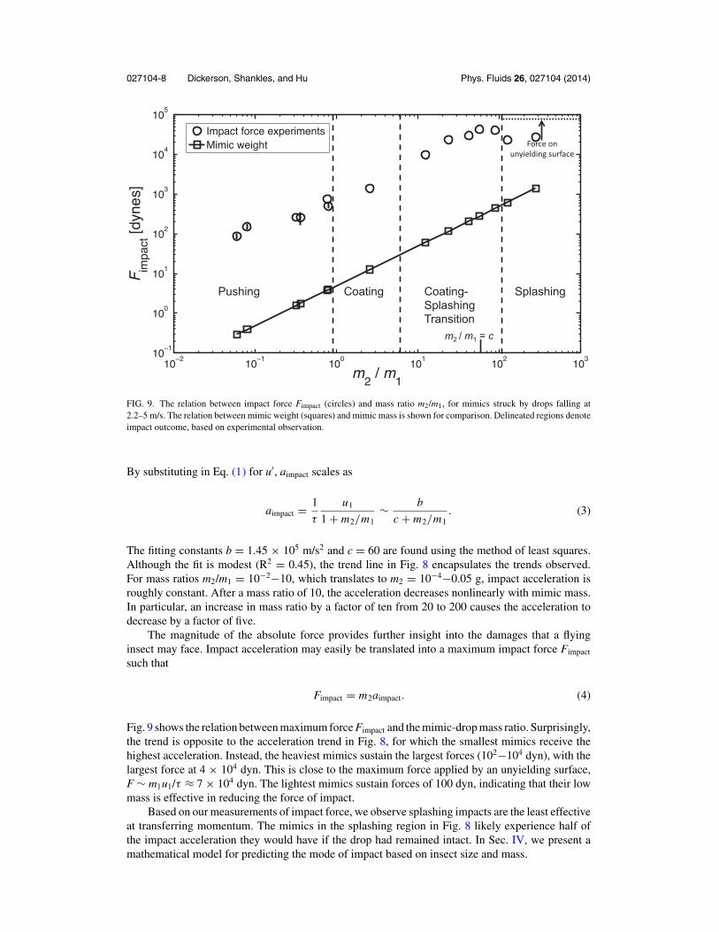
FIG. 9. The relation between impact force Fimpact (circles) and mass ratio m2/m1, for mimics struck by drops falling at2.2–5 m/s. The relation between mimic weight (squares) and mimic mass is shown for comparison. Delineated regions denoteimpact outcome, based on experimental observation.
By substituting in Eq. (1) for u′, aimpact scales as
aimpact = 1
τ
u1
1 + m2/m1∼ b
c + m2/m1. (3)
The fitting constants b = 1.45 × 10⁵ m/s2 and c = 60 are found using the method of least squares.Although the fit is modest (R2 = 0.45), the trend line in Fig. 8 encapsulates the trends observed.For mass ratios m2/m1 = 10−2−10, which translates to m2 = 10−4−0.05 g, impact acceleration isroughly constant. After a mass ratio of 10, the acceleration decreases nonlinearly with mimic mass.In particular, an increase in mass ratio by a factor of ten from 20 to 200 causes the acceleration todecrease by a factor of five.
The magnitude of the absolute force provides further insight into the damages that a flyinginsect may face. Impact acceleration may easily be translated into a maximum impact force Fimpact
such that
Fimpact = m2aimpact. (4)
Fig. 9 shows the relation between maximum force Fimpact and the mimic-drop mass ratio. Surprisingly,the trend is opposite to the acceleration trend in Fig. 8, for which the smallest mimics receive thehighest acceleration. Instead, the heaviest mimics sustain the largest forces (102−104 dyn), with thelargest force at 4 × 10⁴ dyn. This is close to the maximum force applied by an unyielding surface,F ∼ m1u1/τ ≈ 7 × 10⁴ dyn. The lightest mimics sustain forces of 100 dyn, indicating that their lowmass is effective in reducing the force of impact.
Based on our measurements of impact force, we observe splashing impacts are the least effectiveat transferring momentum. The mimics in the splashing region in Fig. 8 likely experience half ofthe impact acceleration they would have if the drop had remained intact. In Sec. IV, we present amathematical model for predicting the mode of impact based on insect size and mass.

027104-9 Dickerson, Shankles, and Hu Phys. Fluids 26, 027104 (2014)
IV. MODEL
In this section, we present a theory for the mass and size range for the three distinct modesof impact, shown graphically in Fig. 2. In the push regime, the impact is inelastic, and so thekinetic energy may be easily calculated using Eq. (1). We will use this relation to calculate theconditions for the push-coat and push-splash thresholds. We seek a relation between the object massand radius that yields an impact that is just on the border of pushing and coating. Our strategy is touse conservation of energy to yield a relation between two regimes. We use a similar method forcalculating the conditions distinguishing a push from a splash impact. Finally, we consider a forcebalance to investigate the threshold between coating and splashing. In the theory below, this insectis assumed to spherical for simplicity, but modifications can be made for other insect shapes.
A. Dimensionless parameters
In the following analysis of raindrop impact onto a free-flying insect, a number of dimensionlessgroups arise upon non-dimensionalization of our governing equations. The groups are typical of bothtwo-body impact problems, e.g., Eq. (1), and in studies of drop impact. The groups include
α = m2
m1 + m2= mimic mass
combined massβ = R1
R2= drop radius
mimic radius
Re1 = R1u1
ν= drop inertia
drop viscosityWe1 = ρu2
1 R1
σ= drop inertia
drop surface tension. (5)
The first two groups describe relative masses and sizes of the two bodies. The group α relates theinertia of the insect to the combined inertia of the drop-cum-insect, and emerges upon considerationof the kinetic energy before and after impact. The group β relates the relative sizes of the two objects,which is important in considering surface energy involved. Specifically, β2 relates the surface areasof the drop to the mimic. The next two dimensionless groups are quite common in drop impactproblems. Reynolds and Weber numbers for the drop size and speed considered in our model areRe1 = 5300 and We1 = 365, respectively, where the properties of the drop include water density ρ =1000 kg/m3, kinematic viscosity ν = 10−6 m2/s, and surface tension σ = 72.8 dyn/cm. The Reynoldsnumber is used in calculation of dissipated energy within the boundary layer within the drop as itstrikes the mimic. The Weber number indicates the importance of the drop’s inertia to capillarity.In studies of impact on unyielding surfaces, large Weber number typically indicates splashing.25
However, in the case of impact on a free target of variable mass, the outcome depends on the massand size of the object as we determine in the analysis below.
B. Push-coat threshold
We employ an energy balance on the drop before and after impact41, 42 to predict the transitionfrom a drop’s pushing its target downward to the drop coating its target. Denoting the post-impactenergy using primed notation, conservation of energy states
Ek + E p + Es︸ ︷︷ ︸before impact
= Ek′ + E p
′ + Es′ + Ed
′︸ ︷︷ ︸after impact
, (6)
where Ek, Ep, Es, and Ed are kinetic, potential, surface, and dissipative energies, respectively. Massconservation dictates the mass of the drop remains unchanged throughout the impact: namely,m1 = m ′
1. We take E p = E p′ by assuming the drop does not substantially change in elevation with
respect to the target just prior to and after the collision.At the border of coating and pushing, the impact is inelastic and the drop surrounds a spherical
target and remains adhered as in Fig. 2. Initial kinetic and surface energies, Ek and Es, remainunchanged for all impacts. We calculate E ′
s and E ′d based upon the lowest-energy coating scenario,
considering the flows that occur as the drop deforms from a sphere to a spherical shell coatingthe mimic. At conditions away from this threshold, the assumptions we have made about drop

027104-10 Dickerson, Shankles, and Hu Phys. Fluids 26, 027104 (2014)
deformation and impact kinetics become inaccurate. We therefore define a term which captures theerror in our calculation of the energy balance in Eq. (6), given by
E = Ek + Es − E ′k − E ′
s − E ′d . (7)
The sign of E determines which impact mode will be witnessed. During pushing, the drop doesnot form a complete spherical shell around the mimic, and so our method overestimates the surfaceE ′
s , and dissipative E ′d , energies. Thus, we expect the error E to be negative if the impact is a push.
Conversely, a faster incoming drop would flow around the target and continue past it as in Fig. 7.This would lead to more residual kinetic energy E ′
k than that calculated using an inelastic impact,and so an underestimated E ′
k . Thus, we expect the error E to be positive if the impact is a coat.Together, our relation for distinguishing pushing from coating is
E
{< 0 push
> 0 coat.(8)
To complete this analysis, we now write relations for all the terms in Eq. (7). The initial kinetic andsurface energies of the system may be written as that of a spherical drop,
Ek = 1
2m1u2
1, (9)
Es = 4πσ R21 . (10)
These energies are converted into several terms throughout the impact process, including the finalkinetic and surface energies of the drop-cum-mimic, and the irrecoverable dissipation during impact.We now estimate these final energies of the system post-impact.
The final kinetic energy is estimated as that for inelastic impact,
E ′k = Ek,inelastic = 1
2(m1 + m2) (u′)2, (11)
where we use Eq. (1) to substitute for u′. This equation represents the greatest possible kineticenergy change for the system, as inelastic impact slows the drop more than other impact types. Thisestimate will be accurate for pushing, but will be an underestimate for high-speed coating flows inwhich the fluid continues flowing past the mimic.
We write the final surface energy as that associated with a spherical shell surrounding its targetas illustrated by Fig. 2. This surface energy is comprised of the energy in the solid-liquid surfaceand the air-liquid surface,
E ′s = 4πσ R2
2 (1 − cos θ )︸ ︷︷ ︸solid-liquid surface
+ 4πσ(R3
1 + R32
) 23︸ ︷︷ ︸
air-liquid surface
, (12)
where θ is the contact angle of water on the target.Viscous dissipation arises from the drop’s deformation upon impact. The time-scale of defor-
mation is τ ≈ 2R1/(u1 − u′). To calculate dissipation, we apply a method, by Pasandideh-Fard41 andMundo,42 for estimating dissipation during impact of drops onto flat surfaces. Dissipation occurs asthe fluid undergoes shear within the boundary layer. Using stagnation point flow, this layer can beestimated to be of thickness41 δ = 4R1/
√Re, where the Reynolds number Re =R1(u1 − u′)/ν. The
viscous dissipation per unit mass34 is = μ(
∂vi∂x j
+ ∂v j
∂xi
)∂vi∂x j
≈ ρν(u1 − u′)2/δ2.
The volume of the boundary layer is approximated by considering the deformation of a drop intoa spherical shell that encapsulates the impacted object. At the end of the impact, the drop assumes aspherical shell of thickness h = (R3
1 + R32)
13 − R2. We model this process as the flattening of a drop
of radius R1 to Rmax =√
4R32/3h, where Rmax is the effective radius of a disc of height h and the
original volume of the drop. The volume of fluid over which dissipation takes place is approximated

027104-11 Dickerson, Shankles, and Hu Phys. Fluids 26, 027104 (2014)
by � ≈ π R2maxδ. The total dissipation, E ′
d , within the drop is
E ′d =
∫ τ
0
∫�
d� dt ≈ �τ. (13)
The energy lost due to viscous dissipation may be approximated by substituting , �, and τ intoEq. (13), yielding
E ′d = 1
2ρνπ R2
max(u1 − u′)√
Re. (14)
By substituting Eqs. (9)–(12) and (14) into Eq. (6) and rearranging, we arrive at
E = 1
2
[m1u2
1 − (m1 + m2) (u′)2] + 4πσ
[R2
1 − R22 (1 − cos θ ) − (
R31 + R3
2
) 23
]−1
2ρνπ R2
max
(u1 − u′)√
Re,
(15)
where m2 and R2 are the only non-constant terms.We may non-dimensionalize Eq. (15) by dividing by ρπu2
1 R31, yielding a dimensionless energy
E∗ = α
[1 − (Re1)−
12
β(β3 + 1)13 − β
]+ 6
We1
[cos θ − (1 + β)
23
], (16)
where α and β are defined in Eq (5) and our push-coat criterion is
E∗{
< 0 push
> 0 coat.(17)
Equations (16) and (17) are physically consistent in light of limits of dimensionless groupsinvolved. Note the second term in Eq. (16) is negative because 0◦ < θ < 180◦. Thus, for very lowinertia or very high surface tension, We1 → 0, E* decreases, indicating that pushing the target isnow favorable. In the limits of either high viscosity, Re1 → 0, or for superhydrophobic targets, cos θ
→ −1, the dimensionless energy E* decreases, promoting pushing. We plot the curve given byEq. (16) in Fig. 4 to predict the threshold between pushing and coating, by specifying values of m2/m1
and plotting values of R2/R1 for which E* = 0. No free parameters are employed in computing thepush-coat transition Eq. (15).
C. Push-splash threshold
In Sec. IV B, we determine the threshold between the push and coat modes. In coating, weassume the drop completely coats its spherical target. In this section, we use observations fromour experiments to make several modifications to this physical picture to consider splashing. First,more residual kinetic energy remains in splashing than in coating at the end of the impact. Second,splashing coats the target less than a coating impact.
In this section, we calculate the final kinetic energy E ′k using an inelastic impact model, and
the final surface E ′s and dissipative E ′
d energies using a model for drop deformation, or flattening,upon impact. If the drop’s initial kinetic Ek and surface Es energies are too high to be absorbed intosurface energy and dissipation, the drop will splash. Our model for E ′
k , E ′s , and E ′
d becomes invalidif the drop breaks apart, but remains valid if the drop stays intact.
We begin with Eq. (13) as before, but consider instead the boundary layer volume � ≈ π
(R1 + χ )2δ occupied by a disk of radius R1 + χ and height δ. We apply a method we previously usedto model the deformation of a drop upon a sphere.10 Impact increases the radius R1 by an amount χ ,
χ
R1∼
√We1
(m1
m2+ 1
)−1
. (18)
027104-12 Dickerson, Shankles, and Hu Phys. Fluids 26, 027104 (2014)
A more detailed derivation of Eq. (18) may be found in Dickerson et al.10 For the remainder ofthis section, we use a scaling factor of unity in Eq. (18); this scaling factor will be used as a freeparameter when when we compare our theory to experiment in Section V. Combining Eq. (18) withEq. (13), and now using R1 + χ in place of Rmax to determine the volume of dissipating fluid �, wearrive at the dissipation
E ′d ≈ �τ ∼ 1
2ρνπ (R1 + χ )2 (u1 − u′)
√Re. (19)
Assuming the drop flattens into a disc upon impact, we estimate the final surface energy as thesum of the solid-liquid energy and the air-liquid energy,
E ′s = πσ (R1 + χ )2 (2 − cos θ ) . (20)
Combining Eqs. (9)–(11) and (18)–(20) for the push-splash threshold, we may rewrite Eq. (7)as
E = 1
2
[m1u2
1 − (m1 + m2) (u′)2] + πσ
[4R2
1 − (R1 + χ )2 (2 − cos θ )]
−1
2ρνπ (R1 + χ )2 (u1 − u′)
√Re,
(21)
where m2 is the only non-constant term.We may non-dimensionalize Eq. (15) by dividing by ρπu2
1 R31, yielding a dimensionless energy
E∗ = 2
3α + 4
We1−
(1 + 2α
√We1 + α2We1
) [2 − cos θ
We1+ α
32
2√
Re1
], (22)
and our push-splash criteria as
E∗{
< 0 splash
> 0 push.(23)
In Eq. (22), we can reason that as m1 increases, the corresponding decrease in the combined massratio α will increase E*, promoting pushing. This is consistent with our experiments, in whichdecreasing m2/m1 produces smaller drop deformations and subsequently, pushing.10 Similarly, as thetarget becomes more hydrophobic, cos θ → −1, E* will decrease, promoting splashing. We plotthe vertical line given by Eq. (22) in Fig. 4 to predict the threshold between pushing and splashing,by specifying values of m2/m1 for which E* = 0. Unlike Sec. IV B, the energy balance givenin Eqs. (21) and (22) has no dependence on R2/R1. Such a result occurs because we assume dropdeformation is unaffected by mimic size in Eq. (18). We justify this approximation in the regime inwhich mimic radius exceeds drop radius (R2/R1 > 2), which is the region of interest, as shown inFig. 4.
D. Coat-splash threshold
At the threshold of coating and splashing, the drop deforms beyond a point where pushing ispossible. The drop flattens sufficiently that it forms a thin film on the top of the target, after whichtwo outcomes can occur: it can remain adhered, creating a coat, or shed off in a ligament or drops,creating a splash. Consideration of attachment or separation from the target’s curved surface is asolved problem called the teapot effect.43 To determine the conditions for distinguishing a coat froma splash, we consider a force balance between inertial and adhesive forces for the flow around acurved surface.44
Duez et al.44 report a critical Weber scaling that characterizes the transition between fluidattachment and separation. We apply their theory using the relative velocity between drop andmimic, u1 − u′, and the length scale given by the film thickness e0 R2
1/2R2, estimated from the

027104-13 Dickerson, Shankles, and Hu Phys. Fluids 26, 027104 (2014)
Bernoulli equation, to define a Weber number,
We∗ = ρ(u1 − u′)2e0
σ. (24)
A radial force balance equates centrifugal forces with the adhesion forces of the fluid to thesphere. This force balance can be written in non-dimensionalized form
We∗ ∝ R22
e20
(1 + cos θ ) . (25)
During splashing, inertial forces dominate and so Weber number is above the critical value above.Thus,
We∗{
< R22 (1 + cos θ ) /e2
0 coat
> R22 (1 + cos θ ) /e2
0 splash.(26)
By equating expressions for We∗ given by Eqs. (24)–(26), we write the condition for splashing,
R2 <
[ρR6
1(u1 − u′)2
σ (1 + cos θ )
] 15
. (27)
We may non-dimensionalize Eq. (27) by dividing by ρπu21 R3
1, yielding a radius ratio
R2
R1<
[α2We1
(1 + cos θ )
] 15
. (28)
A drop with a very high initial velocity, producing a large We1, and a target with a hydrophobicsurface such that cos θ → −1, promotes splashing by increasing the right-hand-side of Eq. (28).We plot the curve specified by the threshold given in Eq. (28) by specifying values of m2/m1 andplotting values of R2/R1, which satisfy the equality. No scaling coefficient was required to shift thecurve to the intersection of the curves plotted by Eqs. (16) and (22).
V. COMPARISON OF THEORY TO EXPERIMENT
Previously, we presented implicit equations, Eqs. (16), (22), and (28), for the mass-radiuscoordinates of each impact mode. We use Mathematica to numerically solve these equations byinputing a mass ratio m2/m1 and calculating a corresponding radius ratio R2/R1 which solves theequations. Although insects are hydrophobic, we perform experiments with hydrophilic mimics.Thus, we assume in our calculations that the contact angle of water on the mimics is θ = 80◦.
We have freedom to choose where to terminate each curve, and so we terminate curves givenby Eqs. (16) and (22) at their point of intersection. For the push-splash transition, in Eq. (18), weuse a free parameter of 0.7 to shift the curve given by Eq. (22), such that the curve segregates ourexperimental data points appropriately. As shown in Fig. 4, our theoretical predictions for impactmode match well our experimental observations. Only a few points stray from their predicted zones.We proceed to use our findings to predict impact phenomenon on organisms.
A. Predictions for insects and flying robots
Fig. 3 shows the predicted impact modes for various insects. The model predicts that insectsabove 100 mg will splash, which seems quite feasible. Inaccuracies are due to our modeling theinsect wing, which is flat, as a curved surface. Consequently, the smallest insects lie at the coating-pushing border rather than within the push regime. Mosquitoes in particular are known to be pushedby raindrops.10 Another inaccuracy is in the coat regime: four insects lie just within the coat regimerather than within the push regime.
We apply our model to predict the effects of raindrop impact on flying robots. We consider fourrobots, including Harvard’s Microrobotic Fly, Cornell’s Micro-Air Vehicles I-II, and the Delfly,1–4
whose mass and half their wingspan is given in Fig. 3. All robots are within the splashing zones.
027104-14 Dickerson, Shankles, and Hu Phys. Fluids 26, 027104 (2014)
Pushing is not possible, as the robots are 2−4 orders of magnitude too heavy, and 1–2 orders ofmagnitude too large. Most would need radii two orders of magnitude less than their current values tobe in danger of coating. The Harvard microrobotic fly is most in danger of coating: if its wingspanwere 3 mm rather than 1 cm, its wings would be coated by the drop. In fact, it is likely that parts ofthe body which are more slender than the wings will be coated if they are struck by a drop.
B. Acceleration and force resistance for small and large insects
We now consider the effects of scaling on raindrop impact. Scaling is particularly useful asflying insect masses range over 6 orders of magnitude, and synthetic flyers span an additional orderof magnitude.
We consider two regimes, the limit of very lightweight and very heavy insects. Small insectshave an impressive ability to survive very large accelerations. For example, fleas can survive 135g during jumping, and a mosquito 300 g during raindrop impact.10 This increasing tolerance toacceleration at small sizes can be explained using scaling.
Fig. 3 shows that impact accelerations aimpact/g asymptote to a constant value of 250 for smallsizes. This value arises from consideration of Eq. (3), for which the acceleration due to dropimpact, aimpact ≈ b
c+m2/m1= b/c
1+m2/cm1. For small insects, which have a mass m2 � cm1 = 0.3 g,
the acceleration due to drop impact approaches a constant, b/cg ≈ 250. Although this accelerationis high, smaller insects, are relatively more capable of surviving accelerations. This increasingstrength at small sizes is due to the strength scaling of materials, observed first by Leonardo daVinci, and reported by McMahon45 and Schmidt-Nielson.46 Materials of the same composition havea constant yield stress, and so the maximum force Fmaterial a material can withstand scales as itscross-sectional area, Fmaterial ∼ m2/3
2 . Using Newton’s second law, Fmaterial = m2amaterial, the impactacceleration a material can withstand scales as amaterial ∼ m−1/3
2 . As insects become smaller, themaximum acceleration a material can withstand will exceed that provided by a raindrop: amaterial >
aimpact. Thus, smaller insects are invincible with respect to acceleration caused by drop.As insects increase in size, the force of raindrop impact becomes small compared to both the
insect weight and the force their materials can withstand. Fig. 9 shows that as an insect grows larger,the force from a raindrop asymptotes to a constant value of 104 dyn. This results from considerationof Eq. (4), for which the force due to drop impact, Fimpact ≈ bm2
c+m2/m1= bm2m1
cm1+m2. For large insects,
which have a mass m2 � cm1 = 0.3 g, the force due to drop impact Fdrop approaches a constant, bm1
≈ 7 × 10⁴ dyn. This scaling is adaptive for larger insects, which become relatively more capable ofsurviving force. The force of raindrop impact will be exceeded by both an insect’s weight, scalingas m2, and the force its materials can withstand, which scale as m2/3
2 . A small bird with mass m2
= bm1/g = 74 g receives an impact force equal to its weight. A Ladybird of mass 2 g receives animpact force 1/10 of its weight.
VI. DISCUSSION
Our experiments involve several assumptions and simplifications which we review here. Sincefast drops cannot be easily aimed at our mimics, we employ drops of speed u1 = 2.2−5 m/s, which is45%–75% slower than a terminal-velocity raindrop. Experiments conducted with terminal raindropswould produce modifications to regimes in Fig. 4. Specifically, coating and splashing would occurfor lower radius R2 and mass m2 values. In addition, the acceleration and force on an insect willincrease (Fig. 9), as a greater amount of momentum is available for transfer to the object. Finally,we assume only spherical drops of fixed size. However, as discussed by Reyssat,7 raindrops have arange of size and shape. In particular, our transition lines in Fig. 4 may not be robust to changes indrop shape.
Wings and legs increase the force of raindrop impact by increasing the insect’s aerodynamicresistance. During the high accelerations applied, these structures provide added mass to the insectand shift points to the right in Figs. 3 and 4. Insects with the largest wings for their size such asbutterflies will experience the greatest deviation from the predicted trends. Wings induce splashingat mass values smaller than predicted in Fig. 3.

027104-15 Dickerson, Shankles, and Hu Phys. Fluids 26, 027104 (2014)
Behavior of the insect will not likely influence impact force. The maximum speeds of mostinsects is less than 10 m/s, the terminal speed of a falling raindrop.47 Even at slow flight speeds,however, the formation of a boundary layer as a result of wing motion may help to dispel the smallestdrops. For instance, it is known the boundary layers formed on discs spinning at exceedingly highspeed may prevent drops from impacting the surface.48
In this study, we consider the impact outcome of a raindrop striking an insect. Conversely, onemight consider the fate of the insect during impact: does it fragment or splash upon striking anincoming object? From our experiments and theoretical analysis in Sec. V B, we conclude that aninsect will not break apart from the force of a raindrop impact. However, as we know from commonexperience, insect splashing does occur upon impact with automobiles. This splashing is due tothe high impact force imparted by the high momentum of the automobile. For example, if a 2-mgmosquito is struck by an automobile traveling at 15 mph = 6.7 m/s, it will experience an impact forceof 9000 dyn, which is comparable to the force required to kill a mosquito. Larger insects may evensplash. If that same car strikes a 1-cm long 0.3 g insect, which is 150 times heavier than a mosquito,the insect will experience an impact force of 240 000 dyn. A car traveling at higher speeds wouldgenerate even higher impact forces, which explains why a car driving at 50 mph is often coveredwith dead splattered insects.
VII. CONCLUSION
We perform raindrop impact experiments on free-falling insects and their mimics. By systemati-cally varying the size and mass of the mimics, we observe three distinct impact modes which we referto as pushing, splashing, and coating. In our supporting theoretical study, we derive mathematicalrelations for the regime of object mass and size associated with each impact mode. These regimesare consistent with our experimental observations. The push-coat and push-splash transitions aredetermined from consideration of energetics, whereas the coat-splash transition is determined fromthe balance of centrifugal and adhesive forces.
Our study shows how flying in the rain is strongly affected by body size. Our lightest mimicsexperience the highest impact accelerations of 300 g, but the lowest absolute forces of 100 dyn.Conversely, the heaviest mimics experience the lowest accelerations of 20 g, but the highest impactforces of 4 × 10⁴ dyn. Based on our experiments with both mimics and insects, we predict insectssmaller than 2 mg are pushed by raindrops, whereas larger insects cause raindrops to splash.Consequently, a modern MAV causes raindrops to splash, and should be designed to withstand thisforce and to contend with splashes shed on its body.
We also identify a sub-optimal size for which objects are most poorly suited for dealing withrain. Objects experience both peak acceleration and peak force at a critical mass of 0.3 g, about theweight of a bumblebee. Biological organisms and synthetic flyers should avoid this mass if they areto minimize acceleration and force due to rain.
ACKNOWLEDGMENTS
We thank Nihar Madhavan for his early experimental contributions and National Science Foun-dation (NSF) CAREER (PHY-1255127) for financial support.
1 R. Wood, “The first takeoff of a biologically inspired at-scale robotic insect,” IEEE Trans. Robotics 24, 341–347 (2008).2 G. De Croon, K. De Clercq, R. Ruijsink, B. Remes, and C. De Wagter, “Design, aerodynamics, and vision-based control
of the DelFly,” Int. J. Micro Air Vehicles 1, 71–97 (2009).3 C. Richter and H. Lipson, “Untethered hovering flapping flight of a 3D-printed mechanical insect,” Artif. Life 17, 73–86
(2011).4 F. Van Breugel, Z. Teoh, and H. Lipson, “A passively stable hovering flapping micro-air vehicle,” Flying Insects and
Robots (Springer, 2010), pp. 171–184.5 G. J. Amador, Y. Yamada, M. McCurley, and D. L. Hu, “Splash-cup plants accelerate raindrops to disperse seeds,” J. R.
Soc. Interface 10, 0880 (2013).6 D. Attenborough, Life in the Undergrowth (BBC One, 2005).7 E. Reyssat, F. Chevy, A.-L. Biance, L. Petitjean, and D. Quere, “Shape and instability of free-falling liquid globules,”
Europhys. Lett. 80, 34005 (2007).

027104-16 Dickerson, Shankles, and Hu Phys. Fluids 26, 027104 (2014)
8 C. Voigt, K. Schneeberger, S. Voigt-Heucke, and D. Lewanzik, “Rain increases the energy cost of bat flight,” Biol. Lett. 7,793–795 (2011).
9 V. Ortega-Jimenez and R. Dudley, “Aerial shaking performance of wet Anna’s hummingbirds,” J. R. Soc. Interface 9,1093–1099 (2011).
10 A. K. Dickerson, P. G. Shankles, N. M. Madhavan, and D. L. Hu, “Mosquitoes survive raindrop collisions by virtue oftheir low mass,” Proc. Natl. Acad. Sci. U.S.A. 109, 9822–9827 (2012).
11 T. Weis-Fogh, “Quick estimates of flight fitness in hovering animals, including novel mechanisms for lift production,” J.Exp. Biol. 59, 169–230 (1973).
12 A. R. Ennos, “The kinematics and aerodynamics of the free flight of some Diptera,” J. Exp. Biol. 142, 49–85 (1989).13 S. N. Fry, R. Sayaman, and M. H. Dickinson, “The aerodynamics of hovering flight in Drosophila,” J. Exp. Biol. 208,
2303–2318 (2005).14 C. Ellington, “The aerodynamics of hovering insect flight. III. Kinematics,” Philos. Trans. R. Soc. London, Ser. B 305,
41–78 (1984).15 C. Ellington, “The aerodynamics of hovering insect flight. II. Morphological parameters,” Philos. Trans. R. Soc. London,
Ser. B 305, 17–40 (1984).16 Y. Liu and M. Sun, “Wing kinematics measurement and aerodynamics of hovering droneflies,” J. Exp. Biol. 211, 2014–2025
(2008).17 R. Dudley, “Extraordinary flight performance of orchid bees (Apidae: Euglossini) hovering in heliox (80% He/20% O2),”
J. Exp. Biol. 198, 1065–1070 (1995).18 R. Dudley and C. Ellington, “Mechanics of forward flight in bumblebees: I. Kinematics and morphology,” J. Exp. Biol.
148, 19–52 (1990).19 A. P. Willmott and C. P. Ellington, “The mechanics of flight in the hawkmoth manduca sexta. II. Aerodynamic consequences
of kinematic and morphological variation,” J. Exp. Biol. 200, 2723–2745 (1997).20 A. P. Willmott and C. P. Ellington, “The mechanics of flight in the hawkmoth Manduca sexta. I. Kinematics of hovering
and forward flight,” J. Exp. Biol. 200, 2705–2722 (1997).21 P. Chai and D. Millard, “Flight and size constraints: Hovering performance of large hummingbirds under maximal loading,”
J. Exp. Biol. 200, 2757–2763 (1997).22 D. Byun et al., “Wetting characteristics of insect wing surfaces,” J. Bionic Eng. 6, 63–70 (2009).23 Y. Zheng, X. Gao, and L. Jiang, “Directional adhesion of superhydrophobic butterfly wings,” Soft Matter 3, 178–182
(2007).24 E. Villermaux, B. Bossa et al., “Drop fragmentation on impact,” J. Fluid Mech. 668, 412–435 (2011).25 A. Yarin, “Drop impact dynamics: Splashing, spreading, receding, bouncing . . . ,” Annu. Rev. Fluid Mech. 38, 159–192
(2006).26 Y. Jiang, A. Umemura, and C. Law, “An experimental investigation on the collision behaviour of hydrocarbon droplets,”
J. Fluid Mech. 234, 171–190 (1992).27 M. Orme, “Experiments on droplet collisions, bounce, coalescence and disruption,” Prog. Energy Combust. Sci. 23, 65–79
(1997).28 M. Rein, “Phenomena of liquid drop impact on solid and liquid surfaces,” Fluid Dyn. Res. 12, 61–93 (1993).29 J. Field, J. Dear, and J. Ogren, “The effects of target compliance on liquid drop impact,” J. Appl. Phys. 65, 533–540 (1989).30 S. Bakshi, I. Roisman, and C. Tropea, “Investigations on the impact of a drop onto a small spherical target,” Phys. Fluids
19, 032102 (2007).31 A. Rozhkov, B. Prunet-Foch, and M. Vignes-Adler, “Dynamics of a liquid lamella resulting from the impact of a water
drop on a small target,” Proc. R. Soc. London, Ser. A 460, 2681 (2004).32 A. Rozhkov, B. Prunet-Foch, and M. Vignes-Adler, “Impact of water drops on small targets,” Phys. Fluids 14, 3485 (2002).33 M. Bussmann, J. Mostaghimi, and S. Chandra, “On a three-dimensional volume tracking model of droplet impact,” Phys.
Fluids 11, 1406 (1999).34 S. Chandra and C. Avedisian, “On the collision of a droplet with a solid surface,” Proc. Math. Phys. Sci. 432, 13–41 (1991).35 D. Hauser, P. Amayenc, B. Nutten, and P. Waldteufel, “A new optical instrument for simultaneous measurement of raindrop
diameter and fall speed distributions,” J. Atmos. Oceanic Technol. 1, 256–269 (1984).36 R. Gunn and G. Kinzer, “The terminal velocity of fall for water droplets in stagnant air,” J. Meteorol. 6, 243–248 (1949).37 C. Clanet, C. Beguin, D. Richard, and D. Quere, “Maximal deformation of an impacting drop,” J. Fluid Mech. 517, 199–208
(2004).38 J. E. McDonald, “Collection and washout of airborne pollens and spores by raindrops,” Science 135, 435–437 (1962).39 J. P. Stapp, “Effects of mechanical force on living tissues,” J. Aviation Med. 26, 268 (1955).40 H. Bennet-Clark and E. Lucey, “The jump of the flea: A study of the energetics and a model of the mechanism,” J. Exp.
Biol. 47, 59–76 (1967).41 M. Pasandideh-Fard, Y. Qiao, S. Chandra, and J. Mostaghimi, “Capillary effects during droplet impact on a solid surface,”
Phys. Fluids 8, 650 (1996).42 C. Mundo, M. Sommerfeld, and C. Tropea, “Droplet-wall collisions: Experimental studies of the deformation and breakup
process,” Int. J. Multiphase Flow 21, 151–173 (1995).43 J. Keller, “Teapot effect,” J. Appl. Phys. 28, 859–864 (1957).44 C. Duez, C. Ybert, C. Clanet, and L. Bocquet, “Wetting controls separation of inertial flows from solid surfaces,” Phys.
Rev. Lett. 104, 084503 (2010).45 T. A. McMahon and J. T. Bonner, On Size and Life (Scientific American Books, New York, NY, 1983).46 K. Schmidt-Nielson, Scaling (Cambridge University Press, New York, NY, 1984).47 C. Ellington, “Limitations on animal flight performance,” J. Exp. Biol. 160, 71–91 (1991).48 O. Povarov, O. Nazarov, L. Ignat’evskaya, and A. Nikol’skii, “Interaction of drops with boundary layer on rotating surface,”
J. Eng. Phys. Thermophys. 31, 1453–1456 (1976).