Railway Corrosion and Stray Currents TTGN3
16
DESIGN STANDARDS STRAY CURRENT MANAGEMENT Tramway Technical Guidance Note 3
Transcript of Railway Corrosion and Stray Currents TTGN3

7/25/2019 Railway Corrosion and Stray Currents TTGN3
http://slidepdf.com/reader/full/railway-corrosion-and-stray-currents-ttgn3 1/16
DESIGN STANDARDS STRAY CURRENTMANAGEMENT
Tramway Technical Guidance Note 3
7/25/2019 Railway Corrosion and Stray Currents TTGN3
http://slidepdf.com/reader/full/railway-corrosion-and-stray-currents-ttgn3 2/16
Contents
Introduction 3
1. Stray current management 4
2. The legal posi tion 5
3. Overall stray current management policy 5
4. Information exchange and co-operation 5
5. Stray current working party (SCWP) 6
6. Appropriate standards 6
7. Electrical design of the system 7
7a. Fundamental principle of stray current design and management 7
7b. Designing to keep stray current low 7
7c. Designing so that rail to local earth voltage remains low 8
7d. Designing so that rail to local earth resistance remains high 9
8. Safety cons iderations 11
8a. Permissible accessible voltages 11
8b. Voltage limiting devices 12
9. Addi tional or special measures 12
9a. Negative earthing and drainage diodes 12
9b. Structures adjacent to the tramway 13
9c. Special arrangements for the depot 13
9d. Other railway traction systems 13
9e. Cathodic protection measures 14
10. Ongoing monitoring and control of stray currents 14
10a. Tests and measurements 14
10b. Construction phase 14
10c. Maintenance during the operational period 15
10d. Renewals of equipment 15
11. Heritage and museum tramways 16
Page 2 of 16
7/25/2019 Railway Corrosion and Stray Currents TTGN3
http://slidepdf.com/reader/full/railway-corrosion-and-stray-currents-ttgn3 3/16
Introduction
This guidance is issued by the Office of Rail Regulation. Following the guidance is notcompulsory and you are free to take other action. If you do follow the guidance you willnormally be doing enough to comply with the law. Railway inspectors seek to secure
compliance with the law and may refer to this guidance as illustrating good practice.
Author
Andy Steel, B Sc, M Sc, C Eng, M I Mech E
At the request of HM Railway Inspectorate and with the assistance of the members of -
• The Light Rail Engineer’s Group
• The ORR Tramway Standards Group
• HM Railway Inspectorate.
Page 3 of 16
7/25/2019 Railway Corrosion and Stray Currents TTGN3
http://slidepdf.com/reader/full/railway-corrosion-and-stray-currents-ttgn3 4/16
1. Stray current management
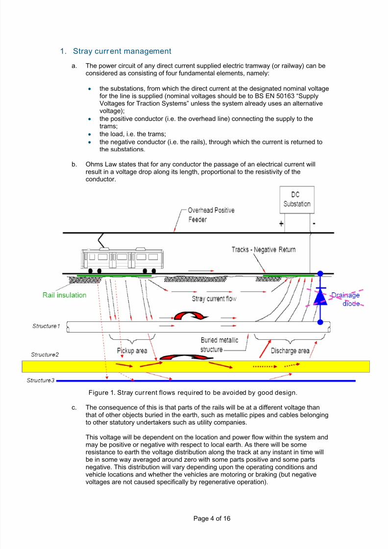
a. The power circuit of any direct current supplied electric tramway (or railway) can beconsidered as consisting of four fundamental elements, namely:
• the substations, from which the direct current at the designated nominal voltage
for the line is supplied (nominal voltages should be to BS EN 50163 “SupplyVoltages for Traction Systems” unless the system already uses an alternativevoltage);
• the positive conductor (i.e. the overhead line) connecting the supply to thetrams;
• the load, i.e. the trams;
• the negative conductor (i.e. the rails), through which the current is returned tothe substations.
b. Ohms Law states that for any conductor the passage of an electrical current willresult in a voltage drop along its length, proportional to the resistivity of theconductor.
Figure 1. Stray cur rent flows required to be avoided by good design.
c. The consequence of this is that parts of the rails will be at a different voltage thanthat of other objects buried in the earth, such as metallic pipes and cables belongingto other statutory undertakers such as utility companies.
This voltage will be dependent on the location and power flow within the system andmay be positive or negative with respect to local earth. As there will be someresistance to earth the voltage distribution along the track at any instant in time willbe in some way averaged around zero with some parts positive and some partsnegative. This distribution will vary depending upon the operating conditions andvehicle locations and whether the vehicles are motoring or braking (but negative
voltages are not caused specifically by regenerative operation).
Page 4 of 16
7/25/2019 Railway Corrosion and Stray Currents TTGN3
http://slidepdf.com/reader/full/railway-corrosion-and-stray-currents-ttgn3 5/16
d. Because the earth is a less than perfect insulator, the potential difference betweenthe rails and nearby buried conductors will result in some of the traction returncurrent “leaking” to earth and some of this total leakage returning to the substation,in part, via those buried pipes. The extent to which this will occur depends upon therelative total resistance of the many possible return paths, via the rails and via otherpipes and the ground.
e. The consequence of stray current is that where it leaves a buried metal object,electrolytic corrosion will occur, frequently in highly localised areas and potentiallyleading to loss of material. However for any significant loss of material to occurneeds current to flow over time. Short duration peaks should not be an issue.
This is clearly undesirable in the case of metallic pipes carrying gas and water, asleakage and/or rupture has obvious safety and/or operational risks to both thetramway and the general public. In the case of cables, particularly the older leadsheathed types, such loss occurs even more rapidly and can lead to breakdown ofthe (now) unprotected inner insulation of the cable. However see Section 5 (2
nd
bullet point) below regarding campaign replacement of such equipment by the utilitycompanies.
2. The legal posi tion
In the early days of tramway electrification, damage to apparatus was a significantissue to the various statutory undertakers who sought to prevent the tramwayoperators from allowing any current to return via the earth. This resulted in a court judgment (National Telephone Company versus Graff-Baker, 1893) which ruled thatthe earth was not exclusively for the use of the statutory undertakers, and that thetramway companies were as entitled to use it as much as they were, providing thatthey did not exceed reasonable limits. These were expressed in terms of maximumvoltage drop in the running rails and promulgated via a series of recommendationspublished over time by the Board of Trade and the Ministry of Transport.
Importantly, it established the principle that some leakage current is inevitable, andthat provided measures are taken to maintain it within reasonable limits, itsexistence has to be accepted by the utility companies and others who elect to burytheir apparatus in the ground.
Such recommendations are now in the form of European Standards which arereferenced below at Section 6.
3. Overall stray current management pol icy
Stray current management has to form an integral part of an overall EMC Policy fora tramway. It must therefore be compatible with the design of the tramway forearthing, bonding and lightning protection.
The electrical design of tramways must, as far as practicable and consistent withoverall safety, be optimised in order that the potential to generate stray currents willbe kept to the minimum practical throughout the life of the system.
This stray current management strategy sets out to assist a tramway todemonstrate, mitigate and manage the stray current risk where this is stillconsidered to be potentially significant during electrical design optimisation.
4. Information exchange and co-operation
It is in the interest of the tramway promoter (this may be the operator or themaintainer) that this will be best achieved by co-operation and information exchangebetween all of the parties involved leading to agreement.
Page 5 of 16

7/25/2019 Railway Corrosion and Stray Currents TTGN3
http://slidepdf.com/reader/full/railway-corrosion-and-stray-currents-ttgn3 6/16
Information exchange and co-operation with all potential stakeholders should becarried out during the planning, design and construction stages. This can continuethroughout the operation of the system when significant changes to the tramway areplanned. In this way, possible effects, suitable precautions and remedies can beassessed. It is also important that the existence of stray currents from other non-tramway sources, (not restricted to other electric railways), is identified.
5. Stray current working party (SCWP)
It is recommended that tramways set up a stray current working party (SCWP) foreach project. It is hoped that all statutory undertakers, particularly the utilitycompanies who have any concerns that their apparatus may be affected by straycurrents, would wish to be involved and contribute to this working party. Thetramway should determine the membership and propose a terms of reference/constitution for the SCWP. It would be hoped that this can be agreed by themembers on a simple majority basis. However the outline issues to be consideredshould include the following:
• to agree the establishment of a schedule of susceptible assets. It should beboth understood that such assets must both be metallic and close to the
tramway rails, and capable of forming an effective path between different partsof the tramway. Continental experience is that provided the measuresdescribed in the sections below are achieved, then buried metallic apparatusover 1metre away from the rails in any direction will not be susceptible to straycurrents;
• cognisance must also be taken of any ongoing programmes to which the utilitycompanies are committed to replacement of apparatus currently metallic withplastic or similar thus reducing the range and extent of susceptible apparatus;
• to scrutinise the project for the electrical system design and stray currentmanagement of the system;
• to agree the level of testing of measures to mitigate stray current during theconstruction phase of the system;
• to agree the level monitoring of change in these measures during the operationphase of the system. This is returned to at Section 10 below;
• to review results of testing during construction;
• to review issues as they arise during the operation phase of the system;
• the frequency of meetings should be by agreement. It will be expected that theneed will vary throughout the life of the project. However once tramwayoperations are established it would be expected that meetings will only berequired where specific issues require to be reported or discussed.
It would be expected that, where appropriate, other statutory undertakers such asNetwork Rail and London Underground may wish to deal with individual tramway
projects in a broader forum which considers other interface issues (such as EMC) aswell as stray currents. The tramway should accommodate this approach.
6. Appropriate standards
The base standard is BS EN 50122-2 (Protective provisions against the effects ofstray currents caused by direct current (DC) traction systems)
1. This applies to all
electrifications of a DC railway or tramway system. The principles may also beapplied to existing electrified systems where it is necessary to consider the effects ofstray currents.
1 It should be noted that as at September 2008, this standard was in the latter stages of revision with a
view to publication in 2009. Cognisance has been taken of this prEN 50122-2 in the preparation of thisGuidance Note. Tramway projects in preparation, or where the design of the electrical system is notcomplete, should be aware of this revised standard and adopt its recommendations where appropriate.
Page 6 of 16

7/25/2019 Railway Corrosion and Stray Currents TTGN3
http://slidepdf.com/reader/full/railway-corrosion-and-stray-currents-ttgn3 7/16
This standard gives comprehensive advice on the design of systems as well asrecommended requirements. The design and management of tramways must meetthe requirements of this European standard.
Inextricably linked with this standard is BS EN 50122-1 (protective provisionsrelating to electrical safety and earthing).
It should always be remembered that the protective provisions against electric shockin this second standard will take precedence over provisions against the effects ofstray currents where safety of staff, or protection of the public, are concerned(Clause 4.1 of BS EN 50122-2 refers). This aspect is returned to later at Section 8.
The following European standard will also be considered during the design process:BS EN 50162 (protection against corrosion by stray current from direct currentsystems). This standard assists with the identification and measurement of potentialcorrosion from stray currents should they still be considered a risk. The straycurrent design and management of the tramway should take account of thisstandard where it is appropriate and following consultation with the SCWP. It shouldbe noted that prEN 50122-2 referred to above has full compatibility with this
standard.
Other standards may be referred to as appropriate. Overall the tramway will bedesigned, constructed and operated to comply with appropriate legislation in force atthe time.
7. Electrical design of the system
a. Fundamental princip le of stray current design and managementIt is not possible to obtain infinite resistance between the tracks and surroundingearth for the full length of the alignment, and certainly not for the life of the tramwayand under varying weather conditions.
Therefore it is possible to limit the risk of stray current, but not to remove it entirely.The design and ongoing management strategy will be to ensure that as far as isreasonably practicable, the level of stray current is minimised.
This principle is in accordance with the standards listed above at Section 6.
b. Designing to keep stray current low For reasons based upon sound experience with early tramway electrificationschemes it is the established convention to determine the insulated overheadconductor as the positive pole of the supply, with the running rails as the negativereturn.
From any point in the system the return current has the possibility of returning to thenegative busbar of the substation by:
• the designated return path (primarily the rails but may include cables as well);or
• via the earth (i.e. as stray current)
The extent to which each path is chosen is governed by Ohm’s Law. This states:
• current = voltage difference / electrical resistance in circuit.
Therefore to keep stray current to a minimum a primary design objective of theelectrical power supply system must be to:
• keep the rail to local earth voltage low; and
• keep the rail to local earth resistance high.
Page 7 of 16

7/25/2019 Railway Corrosion and Stray Currents TTGN3
http://slidepdf.com/reader/full/railway-corrosion-and-stray-currents-ttgn3 8/16
c. Designing so that rail to local earth voltage remains low The tramway will be supplied with electricity suitably transformed and rectified fromthe local electricity network supplier through substations located along the route.The local rail to local earth voltage at any point depends on the overall electricalresistance between that point and the sub-station. Tramways should achieve a lowvalue of resistance in the following manner.
• Frequent feeding points from the traction supply along the alignment thusreducing the distance that return current has to travel. For each feeder point:
o a robust incoming supply at each feeder point must be provided to theextent that this can be arranged with the local electricity networksupplier. Ideally this should be from a ring main rather than a spurconnection. This will keep emergency feeding due to the outage of afeeder point to a minimum;
o in general dual end feeding to each electrical section on the tramwaymust be specified; i.e. each section will be fed from the two adjacent sub-stations. This will reduce the effective distance return current has totravel even further. However care must be taken to ensure that the opencircuit voltages of the two feeding transformers are as equal as possible
(by use of the secondary tapping adjustment) in order to ensure that thetraction load is indeed shared;
o it is also acceptable, but not common practice within Great Britain, toprovide single feeding points at the midpoint of each section, withcoupling switches as necessary to allow for a loss of local supply;
o at the extremities of the line the final section may be single end fed, butthe overall length of the electrical section must be lower to compensate.
• The system must be designed such that the permitted accessible voltage isachieved with any one feeder point out of service. This is defined for GreatBritain at Section 8 below.
• Welding by an approved process of all continuous lengths of rails in order thatthe electrical resistance of the rail is not increased by more than the level
specified in BS EN 50122-2.• Where welding of adjacent rail lengths is not possible then the rails will be
connected by low resistance track bonds. Incorporating sufficient redundancyin bonding must be considered.
• A similar arrangement shall apply at special track installations such as points,crossings, and breather switches/expansion joints. It may be desirable forparallel return conductors to be installed across the length of special work tofacilitate maintenance of the return path during maintenance operations.
• Frequent cross bonding between rails must be provided. In particular this is togive several parallel paths for return current all at equal potential, makingmaximum availability of return conductor capacity and additionally giving a levelof redundancy in event of a failed bond, or rail discontinuity. The bonding shall
encompass:o between both rails of each individual track. Experience has shown that a
bond separation of around 200m is appropriate;
o all four rails on double track. Experience has shown that a bondseparation of around 400m is appropriate for these bonds;
o the actual appropriate intervals for each type of bond must beestablished at the design phase of the tramway.
• The majority of tram projects are “drive on sight” tramways. It should thereforenot be necessary to employ traditional heavy rail signalling track circuitsrequiring impedance bonds or insulated joints unless there are particular site oralignment conditions which require it.
•
Rail sections should be chosen to give the maximum cross sectional area inorder to minimise electrical resistance. Cognisance must be taken of the factthat wear to the rail will cause an increase in resistance over time up to the
Page 8 of 16

7/25/2019 Railway Corrosion and Stray Currents TTGN3
http://slidepdf.com/reader/full/railway-corrosion-and-stray-currents-ttgn3 9/16
point that the rail is renewed. The calculations that determine the maximumaccessible voltage should take into account the renewal limit of wear defined inthe maintenance manual. See also the later reference at Section 7d below tothe ORR technical note “Design Requirements for Street Track”.
• Consideration will be given to providing parallel negative low resistance returncables should the project specific power supply studies show them to be
required at any point of the alignment (see below at Section 8), where it is notpractical for other reasons to use a larger rail section or for example an isolatedsection of single track within a feeder section.
d. Designing so that rail to local earth resistance remains high Tramways should seek to achieve this by ensuring a high level of insulation fromearth of the running rails and the whole return circuit. The design and method ofconstruction should be such that the overall conductance per unit length throughoutthe system must not exceed the values recommended in Table 1 of BS EN 50122-2during routine operations throughout the life of the tramway.
It would be expected that the tramway as initially constructed will have conductancevalues several times better than the values given in the above standard. The
inspection and maintenance regime adopted by the tramway should haveintervention thresholds such that the track conductance values should never reachthe values in the standard during normal operations at any time in the life of thetramway.
The tramway promoter and designer must make absolutely clear and tabulate theconductance values for all track forms at all points of the route to which the systemis being designed, and will be achieved immediately after construction. Theintervention (and eventually renewal) thresholds to which the maintainer of thesystem will be required to achieve throughout, must also be clearly stated in asimilar manner.
The methods of achieving high levels of track insulation will vary according to thetrack form adopted. The following therefore covers the basic principles for theprincipal track forms.
• On open formation where the running rails are laid above ground level as wouldbe expected on a traditional railway formation.
o Sleepers typically of concrete.
o Insulated type rail pads between the rail-foot, the fastener and thesleeper which also meet the required rail toe loads and vibration/frettingperformance.
o Ensure the ballast is:
i. not in contact with the rail as far as possible;
ii. clean;
iii. well drained.
o If grass or similar aesthetic feature is proposed it should be absolutelyclear how contact between the medium proposed and the rails is to beprevented. This may include for the medium to be contained in separatecontainers located around the rails.
o In certain areas it will be expected that the trams will regularly use sandto assist with adhesion. Build up of sand deposits providing any directpath between rail and ballast must be routinely dealt with.
o At points and crossings ensure that there are no direct electrical pathsbetween the rails and any electrical apparatus in the point machine,particularly the neutral and earth connections.
o All other rail-mounted conductive equipment will be insulated from earth.In particular the use of non-metallic connections to drain boxes isrecommended.
Page 9 of 16

7/25/2019 Railway Corrosion and Stray Currents TTGN3
http://slidepdf.com/reader/full/railway-corrosion-and-stray-currents-ttgn3 10/16
o The exposed metal parts of all bonds or other connections to the railmust be kept as short as possible and clear of fasteners, sleepers orballast or any other conductive structure connected to earth.
• On slab track with rails proud of surface.
o For rail pads, bonds and switches, essentially the same issues as forballasted track.
o Run-off and drainage must avoid standing water.
o Prevention of build-up of sand deposits is equally important.
o Measures to be taken with any reinforcement material within the slab aredealt with below at Section 9a.
• On closed formation where the top of the running rail is level with thesurrounding surface. Typical examples will be the highway and pedestrianareas. Guidance as to the physical characteristics of embedded track are givenin the tramway technical guidance note1 (TTGN1) “Design Requirements forStreet Track” (http://www.rail-reg.gov.uk/upload/pdf/ttgn1-StreetTrack.pdf ). Thepoints below relate only to electrical considerations.
• An insulating layer must be interposed between the rails and the surrounding
structure. This can be achieved by the following means:o using a rail coated with insulating material; or
o surrounding the rail with a form of insulated “boot”, or
o embedding the rail in an insulating medium, or
o the use of insulating filler blocks on either side of the rail web;
o it may be acceptable to encapsulate the rail directly in concrete.However in this case the thickness of the concrete and its compositionmust be carefully considered. A minimum thickness of 100mm isrecommended;
o if grass or similar aesthetic feature is proposed it should be absolutelyclear how contact between the medium proposed and the rails is to be
prevented.• The choice and design of the insulating system must be consistent with:
o noise and vibration attenuation policy, but must not compromise theinsulation level. In considering the appropriate solution for a particulararea there must be a clear understanding between the differingrequirements for electrical insulation (essentially a thin layer) and noiseand vibration (which would normally require a thicker layer whichcoincidentally provides electrical insulation);
o all proposed processes which require access to the rail to attend todefects or make new connections, and to undertake routine welding ofrails in order to make good side and head wear.
• Particular attention must be paid to sealing the joint between the rail and the
surface of the surrounding surface to minimise water penetration down the sideof the rail. The method and materials chosen must take account of the extentto which the alignment at any point is shared or crossed by other forms of roadtraffic.
• Particular attention must be paid to local insulation of the rail.
o At all rail welds, particularly if these are carried out after track installation.
o Where rail bonds or negative return cables are attached to the rails.There should be no exposed metal on either the rail, bonds or cablesboth at first installation and after maintenance.
o Attachment and insulation of tie-bars connecting both running rails ifused.
o At any rail joints not capable of being welded. Continuity bonds should
be provided at all such joints.
Page 10 of 16
7/25/2019 Railway Corrosion and Stray Currents TTGN3
http://slidepdf.com/reader/full/railway-corrosion-and-stray-currents-ttgn3 11/16
• Adequate drainage must be provided such that water runs off quickly and doesnot remain in the vicinity of the rails. Drainage must be cleaned regularly sothat ponding does not occur except briefly under the most extreme conditions.
• Standing water must be avoided.
• Rail grooves must be kept clean of debris (including sand deposited from the
tramcars).• At points and crossings ensure that there are no direct electrical paths between
the rails and any electrical apparatus in the point machine.
• Any other rail-mounted equipment must be insulated from earth. Thisparticularly relates to drain boxes and point machines.
• Measures to be taken with any reinforcement material within the slab belowand/or around the track are dealt with below at Section 9a.
8. Safety considerations
a. Permissible accessib le voltages As described above, high levels of insulation between rails and earth means that in
general whilst the tram is operating there will be a potential difference between therails and surrounding earth. Under fault conditions this potential difference can risesignificantly to the extent that it could cause a danger.
There are limits to the permissible accessible voltages due to the traction returncurrent and touch voltages due to currents under fault conditions set by BS EN50122-1 at Clause 7.3. In brief these are:
• accessible voltage for Permanent Conditions will not exceed 120V (except inworkshops where it will be 60V). Clause 7.3.3 refers. However see below forthe particular requirement of HMRI in Great Britain;
• table 4 at Clause 7.3.1 of the above standard for Short-time Conditions (asdefined in the standard);
•
table 5 at Clause 7.3.2 of the above standard for Temporary Conditions (asdefined in the standard).
All tramway projects must meet these limits throughout the life of the system.
It should also be noted that there are specific requirements of HMRI in Great Britainfor tramways. These are currently given in the document Railway Safety Publication2, published by the Office of the Rail Regulator at Page 31, Clause 183. Thisrequires that accessible voltages do not exceed 60V at any point in the system.
As the electrical system design is progressed and tram performance and servicelevels confirmed, each project must conduct a series of computer based powersupply simulations. These will investigate inter-alia accessible and touch voltages at
representative points along the system under normal and emergency (i.e. with thedesigned level of feeder point outage) feeding, and under fault conditions. This willassist in determining whether or not additional measures are required to keep withinthe required limits. A reassessment should always be made when there is anysignificant increase in the level of service proposed or the introduction of newtramcars.
In general any additional measures will relate to reducing further the return circuitresistance by for example the provision of additional return conductors. It will beappreciated that low accessible voltages under permanent conditions will also assistwith the minimising of stray current.
Under fault conditions it may be necessary to connect the return circuit temporarily to
earth until other protection measures (such as tripping to interrupt a short circuitcurrent) become operative. This will be achieved by the provision of voltage limitingdevices. Whilst this gives the risk of a short term increase in the local level of stray
Page 11 of 16
7/25/2019 Railway Corrosion and Stray Currents TTGN3
http://slidepdf.com/reader/full/railway-corrosion-and-stray-currents-ttgn3 12/16
current, safety considerations dictate that this approach is taken. Such events shouldbe both rare and of practically no consequence for third party apparatus.
b. Voltage limiting devices All voltage limiting devices used shall meet the requirements of Clause 7.4 of prEN50122-2 in terms of reset after operation. Ideally this should have the facility to be
monitored through the SCADA system.
Experience has shown that there is a particular failure mode with some types ofvoltage limiting devices. If they experience a high fault current or a large number ofoperational duty cycles due to short-term impermissible accessible voltages thenthey may fail in the short circuit mode. This then creates a direct path to earth forthe traction return which could if undetected for some time lead to corrosion on othernearby metallic structures. Testing and maintenance procedures must take accountof this failure mode.
For this reason hybrid switching types composing of a solid state control andseparate DC contactor are preferred.
9. Addi tional or special measures
a. Negative earthing and drainage diodes On first generation tramway systems, it was accepted practice to connect thenegative pole of the supply, usually a dynamo, to earth, and similarly, to connect allexternal ironwork, such as the traction poles to the running rails. It was alsoaccepted practice to connect buried pipes, etc, to each other and to the runningrails, with the intention that such stray current as did leak out of the rails would bereturned via a solid electrical connection, obviating the risk of electrolytic corrosion.
Whilst having some apparent advantages, this method can result in increasedcurrent leakage simply by increasing the number of potential current paths from therail to the surrounding earth and is therefore flawed in practice because the voltages
that drive stray currents go both positive and negative in normal tram operation.
Initial practice with Great Britain’s second generation tramways was to electricallyconnect all of the steel reinforcement in the track slab and connect this to thenegative terminal of the DC rectifier via a diode. Although this was seen to offer atheoretical advantage by ensuring that the reinforcement should act as a collectormat such that any stray current can only return directly to the substation, it is alsoflawed in practice because the voltages that drive stray currents go both positive andnegative in normal tram operation.
Therefore, current practice, as exemplified by the more recent systems is not toprovide any permanent connections between the negative bus-bar and earth,leaving the rails “floating” relative to earth. As the resistance between the rails and
the earth is not infinite, the rails will adopt an average potential close to that of theearth.
It should be noted that the diodes have been removed in some of the earliertramways with demonstrable improvement in stray current performance.
BS EN 50122-2 is written around this “floating” system. For the avoidance of doubtHMRI require this approach on all new systems.
Where steel meshes or similar reinforcement are used as part of the track form forstructural reasons or as a crack control measure then the tramway must reviewwhether they should continue to be electrically connected. However in that casethey must not be connected to the traction return circuit. Detailed specifications and
design for this should be developed during the design of the track forms.
Page 12 of 16
7/25/2019 Railway Corrosion and Stray Currents TTGN3
http://slidepdf.com/reader/full/railway-corrosion-and-stray-currents-ttgn3 13/16
In general provided that proper attention is paid to the return circuit resistance andinsulation the special provision of a stray current mat should not be required. Itshould be noted that it is common practice amongst established tramway systems inmainland Europe to employ an un-reinforced concrete track slab.
Special requirements may apply to tunnels as described in BS EN 50122-2. Early
consultation with HMRI is recommended.
b. Structures adjacent to the tramwayCare must be taken that the resistance between conductive structures adjacent tothe tramway, which are not insulated from earth, and the track return system, arehigh. The only exception will be at depots which are dealt with below.
Where such structures fall within the zone that it would be possible for a person tobe in contact, directly or indirectly, with both the structure and any conductivematerial connected to the track return then the requirements for accessible andtouch voltages of BS EN 50122-1 must be met.
This will normally involve the use of voltage limiting devices as described above in
Section 8.
c. Special arrangements for the depotFor reasons of the safety of personnel working in the depot the traction return withinthe depot must be directly connected to earth. The depot must be fed from its ownseparate rectifier or power supply. The running rails within the depot must beseparated from the main line by means of insulated rail joints. The layout of thedepot should be planned to avoid any necessity for a tram to be stationary such thatit will bridge these insulated rail joints. Operational procedures should support this.
All of the above will be in accordance with BS EN 50122-1 Clause 9.2.3.4 and prEN50122-2 Clause 9.
It should be noted that a depot site will normally comprise of an area within whichmaintenance activities will be undertaken normally within an enclosed structure,together with stabling areas. The tramway must consider whether the whole site ormerely the maintenance area is to be subject to the above feeding arrangements.The decision will depend upon:
• the overall maintenance philosophy of the tramway; i.e. the extent to whichmaintenance is restricted to one particular area;
• the location of the depot site. Where for example it is contained entirely in an“all enclosed” urban development then it is likely the whole site will require to beconsidered;
• the effect of the current draw when the fleet is stabled but with much of theauxiliary load enabled. This will determine the maximum voltage drop along the
tracks and thus determine whether a direct connection between structural earthand the return circuit is tolerable.
d. Other railway traction systemsCare must be taken to ensure that there will be no direct conductive connection totrack sections of other railway traction systems.
Special arrangements must be taken where conductive structures are adjacent toboth systems (and in the case of alternating current (AC) traction systems arebonded directly to the tracks of the AC system). These arrangements will be agreedwith the owners of each system and must take account of the particular earthing andbonding arrangements on both systems. They must not compromise stray currentlevels on the tramway, except for extremely short periods under fault conditions as
described above in Section 6.
Page 13 of 16
7/25/2019 Railway Corrosion and Stray Currents TTGN3
http://slidepdf.com/reader/full/railway-corrosion-and-stray-currents-ttgn3 14/16
e. Cathodic protection measuresThe overall design including the methods described in this section should ensurethat there will be no consequences due to stray current for third party apparatus.However owners of third party apparatus may still wish to install specific cathodicprotection measures on particular apparatus, as for example described in BS EN12954. The tramway should not be expected to bear the costs of such work or take
any consequences for the performance or monitoring of that apparatus in the future.
10. Ongoing monitoring and control of stray currents
a. Tests and measurementsIt is not practical to directly measure stray currents. The only practical measurementis a local potential difference between the traction return and “mother” earth.
It is sensible to take measurements of this potential difference in order to confirmthat rail potentials stay within a consistent range relative to the design values andthose measured at first installation. This information can then be used to calculatethe track conductance along the route at any point in time thus allowing changes ortrends to be identified and where necessary additional inspection and remedial
actions instigated.
These measurements may be taken on a continuous or discontinuous basis. One ofthe procedures described at Section 10 of prEN 50122-1 and its associated annexesshould be adopted by all new tramway systems. Existing tramways should considerchanging their present arrangements to those described in this standard.
The infrastructure maintainer must use this information continuously, particularly thatof any adverse trends to programme early inspection and remedial action.Intervention thresholds must be clearly defined and acted upon. The methodsoutlined in Section 10c below are a guide to appropriate actions.
By such approach the tramway must demonstrate that it is maintaining its return
circuit insulation at the levels specified in their maintenance instructions. These inturn must be higher than those in the standard BS EN 50122-2.
Provided this is achieved and demonstrated then no other testing regime should berequired.
It is for the utility companies to carry out any additional monitoring of their ownapparatus as a part of their internal inspection and maintenance procedures. Anymeasurement and criteria for intervention due to measured stray-currentinterference for apparatus without cathodic protection must be in accordance withthe procedures given in BS EN 50162. Acceptable positive potential shifts shouldbe as given in Table 1 of the same specification. Notes 1 and 2 to the table shouldbe considered in determining whether the thresholds in Columns 3 or 4 are
appropriate.
In particular it should be noted that as return circuit insulation levels will always behigh compared with soil resistivity changes in the latter locally over time will haveinsignificant effect.
The above should only apply to utility apparatus installed before the granting of theTransport & Works Act Order or equivalent legislation for any tramway project. Itshall be the responsibility of the owner/installer of any new or modified apparatus totake full cognisance of the presence of the tramway and to design and install suchthat the apparatus is not susceptible to corrosion from stray current.
b. Construction phase
The tramway must recognise that the achievement of the agreed design standardsfor track insulation and bonding (see Section 7 above) will require continuous
Page 14 of 16
7/25/2019 Railway Corrosion and Stray Currents TTGN3
http://slidepdf.com/reader/full/railway-corrosion-and-stray-currents-ttgn3 15/16
attention to detail throughout the construction phase of the project. Thereforeprocedures must be documented and in place which:
• continuously review the practicality of the design for construction;
• provide rigorous quality control at all stages;
• carry out formal testing and recording at appropriate stages.
The detail of the above must be developed as the design and procurement proceedsand must be incorporated into the overall project quality and test and commissioningdocumentation.
The above should be shared with the SCWP during the design and constructionphase.
c. Maintenance during the operational periodThe tramway must ensure that a regime of preventative and corrective maintenanceof the system is in place throughout the operating period. Maintenance of returncircuit insulation levels will form a key part of this. The majority of these actions areessentially good house-keeping activities such as:
• monitoring of return circuit potentials, with reaction to changes (see Section 10a
above);
• keeping ballast clean and free of vegetation;
• on grass tracks applying regular vegetation management to ensure no directcontact between the rail and the growing medium;
• keeping drains clear;
• cleaning sand deposits away from rails;
• addressing highway surface failures promptly;
• checking bonds for soundness and that they are still in place (i.e. they have notbeen stolen);
• checking cables for insulation damage; and
• checking protection devices for functionality.
d. Renewals of equipmentOver the operating life of the system equipment of both the tramway and thirdparties will require renewal. This may arise for several reasons:
• life expiry;
• obsolescence;
• damage.
For all renewals it will be appropriate to consider the stray current implications of;
• the point at which renewal is judged necessary. For example the remainingcross sectional area of a rail may be considered more important than the
physical state of the rail head;
• service experience;
• changes in technology or materials.
The quality of renewals, upgrades etc must be, as a minimum, consistent with theoriginal construction. It would also be expected to take account of any changes inlegislation or any appropriate European standards that may have been introduced ormodified since the original construction.
In particular third parties should note that any renewal of their apparatus must takefull cognisance of the presence of the tramway.
Page 15 of 16
7/25/2019 Railway Corrosion and Stray Currents TTGN3
http://slidepdf.com/reader/full/railway-corrosion-and-stray-currents-ttgn3 16/16
11. Heritage and museum tramways
It is accepted that most current heritage and museum tramways will have beenconstructed to meet rules issued many years ago by the Ministry of Transport (seeSection 2).
However all tramway installations have a duty to consider stray current implications.In doing so it should be remembered that for corrosion due to stray current to be anissue significant current must flow for some time.
Therefore such tramways should consider;
• the length of the return path to their feeding point(s) and its specific resistance;
• the maximum current draw to be expected from the tramcars to be operated onthe line, taking into account operating speeds and likely loading;
• the operational periods of the line;
• the level of service to be provided during these operating periods.
They should also consider the likelihood of significant underground metallic services
in close proximity to the alignment of the tramway.
Careful consideration of these points will allow a judgement to be taken as towhether any additional insulation of the traction return would be advisable at times ofrenewal or extension to the existing systems. Consultation with HMRI isrecommended.
All future new museum lines will be expected to follow the main sections of thisguidance note.
Page 16 of 16