Rail Track Corridor Modeling - Bentley Userbentleyuser.se/2015_BUSdagar/Presentationer/Rail Track...
43
Practice Workbook This workbook is designed for use in Live instructor-led training and for OnDemand self study. The explanations and demonstrations are provided by the instructor in the classroom, or in the OnDemand videos for this course available on the Bentley LEARN Server (learn.bentley.com). This practice workbook is formatted for on-screen viewing using a PDF reader. It is also available as a PDF document in the dataset for this course. DO NOT DISTRIBUTE - Printing for student use is permitted TRNC01970-1/0001 Rail Track Corridor Modeling SELECTseries 4 (08.11.09.845) or newer About this Practice Workbook... This PDF file includes bookmarks providing an overview of the document. Click on the bookmark to quickly jump to any section in the file. You may have to turn on the bookmark function in your PDF viewer. Only Metric files are currently included in the dataset. Throughout this practice workbook metric values enclosed in square brackets. For example: [3.4m] Having an appropriate workspace is very important when using the OpenRoads technology. The workspace contains the standards and other design specifications needed to complete your work. This training uses the Bentley-Civil workshop delivered with the software. It is very important that you select the Bentley-Civil workspace when working the exercises in this course.
Transcript of Rail Track Corridor Modeling - Bentley Userbentleyuser.se/2015_BUSdagar/Presentationer/Rail Track...

Practice WorkbookThis workbook is designed for use in Live instructor-led training and for OnDemand self study. The explanations and demonstrations are provided by the instructor in the classroom, or in the OnDemand videos for this course available on the Bentley LEARN Server (learn.bentley.com).
This practice workbook is formatted for on-screen viewing using a PDF reader. It is also available as a PDF document in the dataset for this course.
DO NOT DISTRIBUTE - Printing for student use is permitted
TRNC01970-1/0001
Rail Track Corridor Modeling
SELECTseries 4 (08.11.09.845) or newerAbout this Practice Workbook...
This PDF file includes bookmarks providing an overview of the document. Click on the bookmark to quickly jump to any section in the file. You may have to turn on the bookmark function in your PDF viewer.
Only Metric files are currently included in the dataset. Throughout this practice workbook metric values enclosed in square brackets. For example: [3.4m]
Having an appropriate workspace is very important when using the OpenRoads technology. The workspace contains the standards and other design specifications needed to complete your work.
This training uses the Bentley-Civil workshop delivered with the software. It is very important that you select the Bentley-Civil workspace when working the exercises in this course.

Copyright © 2015 Bentley Systems, Incorporated 2DO NOT DISTRIBUTE - Printing for student use is permitted
Exercise 1: Import Existing Geometry
DescriptionIn this exercise you will select the proper workspace to use the OpenRoads Technology software and import geometry from an ALG to a DGN base geometry file.
Skills Taught Select proper workspace
Define cant alignment in the ALG
Import Geometry from Memory
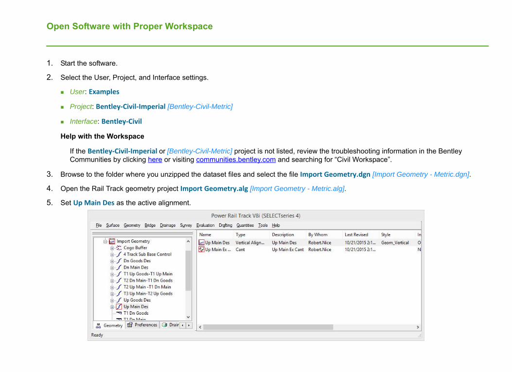
Open Software with Proper Workspace
1. Start the software.
2. Select the User, Project, and Interface settings.
User: Examples
Project: Bentley‐Civil‐Imperial [Bentley-Civil-Metric]
Interface: Bentley‐Civil
Help with the Workspace
If the Bentley‐Civil‐Imperial or [Bentley-Civil-Metric] project is not listed, review the troubleshooting information in the Bentley Communities by clicking here or visiting communities.bentley.com and searching for “Civil Workspace”.
3. Browse to the folder where you unzipped the dataset files and select the file Import Geometry.dgn [Import Geometry - Metric.dgn].
4. Open the Rail Track geometry project Import Geometry.alg [Import Geometry - Metric.alg].
5. Set Up Main Des as the active alignment.

Copyright © 2015 Bentley Systems, Incorporated 4DO NOT DISTRIBUTE - Printing for student use is permitted
Create New Cant Geometry
1. Create new cant geometry in the ALG file.
a. In the Power Rail Track Explorer window, right click on Up Main Des and select New.
b. Set the Type to Cant.
c. Type Des Cant in the Name field.
d. Click Apply.
e. Close the dialog box.
2. Edit cant geometry in the ALG file.
a. In the Power Rail Track Explorer window, right mouse click on Des Cant horizontal geometry and select Edit.
The Cant Alignment Editor appears.
b. Click the Define All button.
c. Set Cant Method to Use Equilibrium Equations.
d. Set the Design Speed to 55 [90].
e. Disable all other check boxes.
f. Click OK to define the cant and close the dialog box.
g. Click Apply to save the new cant geometry.
h. Close the Cant Alignment Editor dialog box.
3. Save the ALG file with the new cant geometry by selecting File > Save > Geometry Project.

Copyright © 2015 Bentley Systems, Incorporated 5DO NOT DISTRIBUTE - Printing for student use is permitted
Import ALG Geometry into OpenRoads Technology Geometry
1. Select Import InRoads from Memory tool from the Civil Tools > General Geometry task menu.
Hint: If the task menus are not displayed, select Tools > Tasks.
2. Import geometry objects from the ALG to OpenRoads Technology geometry.
a. Expand and select the check box next to Alignment.
All of the geometry objects (horizontal, vertical, and cant) are selected.
b. Disable the check box next to Point List.
c. Disable the Create Civil Rules check box.
There is no need for ruled geometry in the rail workflow because the source of all geometry needs to remain in the ALG file. The geometry should not be edited in the OpenRoads Technology environment.
d. Click the Import button.
The Geometry is imported from the ALG to the DGN and is displayed.
3. Review the imported geometry in the view.
The red lines are the rail geometry. The dashed green line is the outer boundary of the terrain data. The terrain was already referenced to this drawing.
Copyright © 2015 Bentley Systems, Incorporated 6DO NOT DISTRIBUTE - Printing for student use is permitted
Exercise 2: Model Rail Corridor
DescriptionIn this exercise you will create multiple corridors for a single track rail and view the results in 3D and cross sections views. Cant geometry from the ALG will also be applied to the corridors.
Skills Taught Create a corridor
Learn to select a corridor
Learn to use corridor design stages
View dynamic cross sections
Create a point control for cant

Copyright © 2015 Bentley Systems, Incorporated 7DO NOT DISTRIBUTE - Printing for student use is permitted
Create Corridor Model Southern Portion of Northbound Track
A recommended practice is to create corridor models, geometry, and terrain in separate files and use referencing to bring them together. In this exercise a corridor is modeled along the southern portion of the Up Main Des geometry. Following recommended practice the corridor is created in a different file than the geometry.
1. Open the file Create Corridor.dgn [Create Corridor - Metric.dgn].
This is a blank file that the corridor will be created in. The Import Geometry.dgn [Import Geometry - Metric.dgn] file is already referenced into this file which is why the geometry that was imported from the ALG is visible. Sharing OpenRoads Technology geometry and terrain is as easy as referencing a file.
2. Select the Element Selection tool.
3. In view 1 select (left mouse click) the Up Main Des geometry.
Hint: Hover the cursor over the graphic to display an information window that includes the geometry (Complex Element) name.
The context tool menu will also appear after selecting the graphic with a left mouse click.
4. When the context menu appears select Create Corridor.
A heads up prompt reading Locate Profile-Reset for Active Profile appears.
5. Reset (right mouse click) to accept the active vertical profile.
6. Type in Up Main Des South for the Corridor Name and press Enter.
7. At the Template prompt, hold down the Alt key and press the Down Arrow key to open the Pick Template dialog.
8. Select Templates > Rail > Single Track ‐ Concrete Sleepers and click OK.
The selected template is added to the heads up prompt field.
9. Data (left mouse click) to accept the template in the heads up prompt field.

Copyright © 2015 Bentley Systems, Incorporated 8DO NOT DISTRIBUTE - Printing for student use is permitted
10. Set the Start Station to 642+55 [19+585] and press Enter key.
11. Data to accept the start station.
12. Set the End Station to 657+80 [20+050] and press Enter key.
13. Data to accept the end station.
14. Set the Drop Interval to 30 [10], press the Enter key, and Data to accept.
15. Set the Minimum Transition Before Drop to 0.
16. Set the Minimum Transition After Drop to 0.
17. Set the Description to Up Main Des South.
18. Reset to exit the corridor tool.
The corridor is created with a single template drop at the beginning. The result is graphic elements visible in view 1.Many of the graphics such as the blue, green, and gray lines running parallel to the alignment at the linear features created from each point in the template.
Other graphic lines represent the corridor itself. All along the length of the corridor are handles that are used for selecting the corridor for editing and other functions such as running dynamic cross sections. These handles are yellow in this file as shown in the image to the right.
Clicking on one of these handles selects the corridor and open a context sensitive menu that contains tools for editing and further processing the corridor as shown below.

Copyright © 2015 Bentley Systems, Incorporated 9DO NOT DISTRIBUTE - Printing for student use is permitted
The template drop is also represented by the graphics with a single handle to the left (looking up station) at the beginning of the template drop.
It is important to understand that these graphics are the corridor. All of the data is stored in the DGN file, there is no longer an external ird file. Changing, or deleting, the graphics changes or deletes the corridor.
Copyright © 2015 Bentley Systems, Incorporated 10DO NOT DISTRIBUTE - Printing for student use is permitted
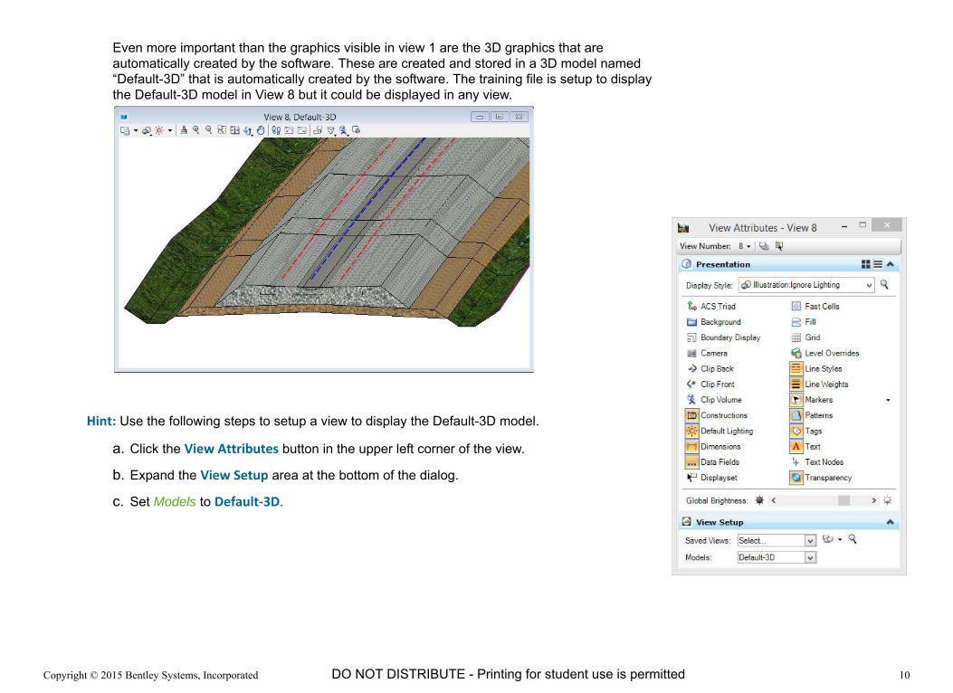
Even more important than the graphics visible in view 1 are the 3D graphics that are automatically created by the software. These are created and stored in a 3D model named “Default-3D” that is automatically created by the software. The training file is setup to display the Default-3D model in View 8 but it could be displayed in any view.
Hint: Use the following steps to setup a view to display the Default-3D model.
a. Click the View Attributes button in the upper left corner of the view.
b. Expand the View Setup area at the bottom of the dialog.
c. Set Models to Default‐3D.

Copyright © 2015 Bentley Systems, Incorporated 11DO NOT DISTRIBUTE - Printing for student use is permitted
Set Corridor Design Stage
Corridor Models have a Design Stage property that affects how the corridor is modeled. The interval specified when the corridor is created defines the distance between drop points where the corridor is modeled. The Design Stage property applies a multiplier to the interval.
For example, a Preliminary design stage has a multiplier of 10. So instead of our model being processed every 10’ [3m] as we specified, it is modeled every 100’ [30m].This is what causes the chording.
The Design Stage also defines when critical sections like horizontal and vertical cardinal points are modeled, and what output is created including top and bottom meshes, linear components and null point lines.
Early in a project using the Preliminary design stage causes the corridor to process faster and typically provides sufficient detail. As the project progresses changing to the design or final design stage results in a more accurate model.
1. Select the Element Selection tool.
2. Select the Up Main Des South corridor handle and from the context sensitive menu select the Properties button on the context menu.
3. Change the Design Stage to 3 ‐ Final.

Copyright © 2015 Bentley Systems, Incorporated 12DO NOT DISTRIBUTE - Printing for student use is permitted
Create Corridor Model for Northern portion of Northbound Track
Create another corridor along the northern portion of the Up Main Des geometry. The two corridors on this project will be connected by a bridge in a latter exercise.
1. Zoom View 1 to the area just north of the corridor created in the previous exercise.
2. Create a new corridor along the norther portion of the Up Main Des geometry using the following parameters.
Refer back to the detailed steps to create a corridor in the previous exercise for assistance if necessary.
* The Start or End station can be locked to the begin or end station by pressing the Alt key. Pressing the Alt key again unlocks the station and allows a station value to be keyed in.
3. Change the corridor Design Stage to 3 ‐ Final.
Profile: Active Profile
Corridor Name: Up Main Des North
Template: Single Track ‐ Concrete Sleepers
Start: 659+45 [20+100]
End: Press Alt key to lock to end station *see below for help
Drop Interval: 30 [10]
Minimum Transition Before Drop: 0
Minimum Transition After Drop: 0
Description: Up Main Des North

Copyright © 2015 Bentley Systems, Incorporated 13DO NOT DISTRIBUTE - Printing for student use is permitted
View Dynamic Cross Sections of the Corridor
1. Select the Up Main Des South corridor handle and from the context sensitive menu select the Open Cross Section Model tool.
2. When prompted to Select or Open View, click in View 5 to display the cross sections.
3. Click the Next Station and Previous Station arrows to browse through the cross sections.
4. Change scale of cross section.
Zoom - Scroll mouse wheel
Vertical Exaggeration - Hold Shift key and scroll mouse wheel
Horizontal Exaggeration - Hold Ctrl key and scroll mouse wheel

Copyright © 2015 Bentley Systems, Incorporated 14DO NOT DISTRIBUTE - Printing for student use is permitted
5. View a dynamic cross section by picking location in plan view.
a. Press and hold the right mouse button in the cross section view until the pop up menu appears.
b. Select Location Station Via Datapoint.
c. Data in the plan view (view 1 in the training file).
A dynamic line appears in the plan view showing the location where the cross section will be cut.
d. Position the cursor and Data to create the cross section.
6. View cross section at 649+00 [19+800].
a. Select the down arrow next to the station number at the top v
b. Type 649+00 [19+800] in the field.
c. Press Enter key.

Copyright © 2015 Bentley Systems, Incorporated 15DO NOT DISTRIBUTE - Printing for student use is permitted
Add Cant to the Southern Corridor
The cant geometry has already been created in the ALG file. In this exercise the cant geometry will be applied to the Up Main Des South corridor.
1. In View 1 zoom to view the southern corridor. Zoom close enough to easily select one of the corridor handles.
2. Select the Up Main Des South corridor handle and from the context sensitive menu select the Corridor Objects tool.
The Corridor Objects tool is an interface to several objects that affect a corridor such as Template Drops and Point Controls. These corridor objects can also be defined and edited using tools that go directly to one specific object. Using the Corridor Objects tool where the object definitions are more visible in a dialog is often helpful as you first learn the software and interface.
3. In the Corridor Objects dialog, select Point Control.

Copyright © 2015 Bentley Systems, Incorporated 16DO NOT DISTRIBUTE - Printing for student use is permitted
4. Create a new point control for the cant.
a. Select the Add New icon at the top of the dialog to add a new point control.
b. Following the heads up prompts create a point control with the following parameters.
Notice that the rail centerline geometry is selected for this point control, not the cant geometry. This is because the cant geometry does not actually exist in this file, it is stored in the ALG file.
The active cant geometry in the ALG for the selected alignment is used by the point control definition. If the active cant geometry in the ALG is changed, the cant in the corridor will update.
Because the cant geometry is read from the ALG it is also critical that the proper ALG file be loaded at all times.
Start: 642+55 [19+585]
End: 657+80 [20+050]
Control Description: Up Main Des South Cant
Mode: Vertical
Control Type: Cant Hint: Press up and down arrows on keyboard to scroll through pick list in heads up interface. Also, press the first letter of the word you are looking for to jump to that part of the list. For example, press c for cant.
Cant Centre Point: C cant
Cant Left Point: L cant
Cant Right Point: R cant
Locate Plan or Profile Element Select the Up Main Des geometry Hint: Use the pop up information when the cursor is hovering over a graphic to verify it is the correct geometry.
Priority: 1

Copyright © 2015 Bentley Systems, Incorporated 17DO NOT DISTRIBUTE - Printing for student use is permitted
5. Review the cross section at 649+20 [19+800] which should now have cant applied to the corridor.

Copyright © 2015 Bentley Systems, Incorporated 18DO NOT DISTRIBUTE - Printing for student use is permitted
Exercise 3: Updating Corridor with Edited Geometry
DescriptionIn this exercise you will learn how to update corridor models with geometry such as cant and vertical alignments edited in the ALG file.
Skills Taught Process Corridor
Import Geometry from Memory
Geometry Reports

Copyright © 2015 Bentley Systems, Incorporated 19DO NOT DISTRIBUTE - Printing for student use is permitted
Define and Apply New Cant Geometry
In this section a second cant definition for a different design speed is created and the corridor model is updated to use this new cant geometry.
1. Create a second cant geometry option for a different design speed in the ALG file.
a. In the Power Rail Track Explorer window, right click on Up Main Des horizontal geometry and select New.
b. Set the Type to Cant.
c. Type Des Cant 2 in the Name field.
d. Click Apply.
e. Close the dialog box.
2. Edit cant geometry in the ALG file.
a. In the Power Rail Track Explorer window, right mouse click on Des Cant 2 and select Edit.
The Cant Alignment Editor appears.
b. Click the Define All button.
c. Set Cant Method to Use Equilibrium Equations.
d. Set the Design Speed to 100 [160].
e. Disable all other check boxes.
f. Click OK to define the cant and close the dialog box.
g. Click Apply to save the new cant geometry.
h. Close the Cant Alignment Editor dialog box.
3. Save the ALG file with the new cant geometry by selecting File > Save > Geometry Project.

Copyright © 2015 Bentley Systems, Incorporated 20DO NOT DISTRIBUTE - Printing for student use is permitted
4. Process corridor with new cant applied.
a. Verify that Des Cant 2 is the active cant alignment in the ALG.
b. Review a cross section that currently has cant applied. Remember how the cant appears so you can compare after the new cant geometry is applied.
c. Select the Up Main Des South corridor handle and from the context sensitive menu select the Process Corridor tool.
Hint: To select the corridor handle the Element Selection tool must be active.
d. Review the same cross section and observe how the cant has updated.

Copyright © 2015 Bentley Systems, Incorporated 21DO NOT DISTRIBUTE - Printing for student use is permitted
Edit Vertical Alignment and Update Corridor Model
All of the geometry for rail projects will be created and edited in the ALG. That geometry is imported into the OpenRoads Technology geometry environment and used in the corridor. In this exercise the vertical geometry is edited to raise the track to the bridge elevation and the corridor reprocessed with the updated vertical geometry.
1. Update vertical geometry in the ALG file.
a. In the Power Rail Track Explorer window, right click on Up Main Des vertical geometry and select Edit.
b. Change the following values for the first curve set.
c. Click Apply to save the changes.
d. Click Next.
e. Change the following values for the second curve set.
f. Click Apply to save the changes.
g. Close the Define Vertical Curve Set dialog.
h. Save the ALG file with the new cant geometry by selecting File > Save > Geometry Project.
Station: 656+15 [20+000]
Elevation: 420 [128.00]
Length: 100 [30]
Station: 662+75 [20+200]
Elevation: 420 [128.00]
Length: 100 [30]

Copyright © 2015 Bentley Systems, Incorporated 22DO NOT DISTRIBUTE - Printing for student use is permitted
Before the updated vertical alignment can be used by the corridor model it must be imported into the DGN file where the OpenRoads Technology geometry is stored.
2. Open the Import Geometry.dgn [Import Geometry - Metric.dgn] file.
3. Review existing geometry in DGN.
a. Select the Element Selection tool.
b. Data on the Up Main Des horizontal alignment in the graphics and select Horizontal Geometry Report from the context sensitive menu.
The Civil Report Browser window appears.
c. Select the VerticalAlignmentReview.xsl report from the left column.
d. Review the first curve. Notice that the PVI is at 663+46.85 [20+222.52] and elevation 409.8 [124.9].
These are the old alignment values, not the updates that were just made to the alignment.
e. Close the Civil Report Browser.
4. Select Import InRoads from Memory from the General Geometry task menu.
The software understands what geometry has already been imported from the ALG and puts a check mark by each of those geometry objects. It is a best practice to not change what the software automatically selected when edits to existing geometry are imported. This ensures the ALG and DGN remain synchronized.
If new geometry has been created in the ALG and needs to be imported it would be necessary to enable the check box next to those new geometry objects.
a. Disable the Create Civil Rules check box.
b. Click the Import button.
The Geometry in the DGN is updated with the latest definitions from the ALG.

Copyright © 2015 Bentley Systems, Incorporated 23DO NOT DISTRIBUTE - Printing for student use is permitted
5. Review updated geometry in DGN.
a. Select the Element Selection tool.
b. Data on the Up Main Des horizontal alignment in the graphics and select Horizontal Geometry Report from the context sensitive menu.
c. Select the VerticalAlignmentReview.xsl report from the left column.
d. Verify that the PVI for the first curve is 656+15 [20+000] and the elevation is 420 [128]. This confirms the updated alignment has been imported.
e. Close the Civil Report Browser.
6. Update corridor model.
a. Open the Create Corridor.dgn [Create Corridor - Metric.dgn] file.
The file containing the geometry is referenced to this file and as will all references is automatically updated whenever a file is opened. Therefore, the updated geometry is immediately available.
b. Review the cross section at 656+15 [20+000] to verify the rail is now at elevation 420 [128.0].

Copyright © 2015 Bentley Systems, Incorporated 24DO NOT DISTRIBUTE - Printing for student use is permitted
Optional Exercise 4: Alternative Cant Method Using Elevation Difference Alignments
DescriptionAn alternate method to define cant is using elevation difference vertical alignments. These alignments define the delta elevation between the centerline profile and the rail profile.
The following exercise uses this alternate cant method for those that may require this workflow. However, unless there is a specific need for this workflow, such as the track geometry being defined outside of Power Rail Track, this workflow is not the recommended best practice. There are more details and less automated updating with this workflow than the workflow described in the previous exercises.
In this exercise you will create new elevation difference vertical alignments in the ALG file, import those into OpenRoads Technology geometry, and create new point controls to use the elevation differences alignments for the rail cant.
Skills Taught Import Geometry from Memory
Set Active Profile
Create Elevation Difference Point Control

Copyright © 2015 Bentley Systems, Incorporated 25DO NOT DISTRIBUTE - Printing for student use is permitted
Alternative Cant Method Using Elevation Difference Alignments
1. Open the Import Geometry.dgn [Import Geometry - Metric.dgn] file.
This file stores all of the DGN based geometry. After the elevation difference vertical alignments are created in the ALG they must be imported to this file before they can be used by the corridor.
2. Create the elevation difference vertical alignments.
a. In the Power Rail Track Explorer window, right click on Des Cant 2 cant geometry and select Edit.
b. Click the Create Rail Diffs button.
Two new vertical alignments named Left Rail and Right Rail are created.
c. Close the Cant Alignment Editor dialog box.
d. Save the geometry project.

Copyright © 2015 Bentley Systems, Incorporated 26DO NOT DISTRIBUTE - Printing for student use is permitted
3. Import the new rail alignments into the DGN.
a. Select Import InRoads from Memory from the General Geometry task menu.
b. Expand the geometry tree to view the new Left Rail and Right Rail alignments.
Notice that these two alignments are not selected. Remember, the software automatically checks all alignments that have already been imported. These two have not been previously imported so they are not selected.
c. Enable the check box next to the Left Rail and Right Rail alignments.
d. Disable the Create Civil Rules check box.
e. Click the Import button.
The Geometry in the DGN is updated with the latest definitions from the ALG including these two new vertical alignments.
The last alignment imported (Right Rail in this example) becomes the “active” profile. This is a problem because both of the corridors are setup to use the active profile for their elevation control.
4. Set the active profile back to the design profile.
a. Open View 2.
b. Select the Element Selection tool.
c. Data on the Up Main Des horizontal alignment in the graphics and select Open Profile Model from the context sensitive menu.
d. When prompted to Select or Open View, click in View 2.
The view shows all three of the profiles associated with the Up Main Des horizontal alignment. The three profiles are the design profile named Up Main Des near elevation 400 [120] and the Left Rail and Right Rail profiles near elevation zero.
e. Zoom to the Up Main Des profile near elevation 400 [120].
f. Data on the Up Main Des profile in the graphics and select Set as Active Profile from the context sensitive menu.

Copyright © 2015 Bentley Systems, Incorporated 27DO NOT DISTRIBUTE - Printing for student use is permitted
5. Disable the existing cant in the Up Main Des South corridor.
a. Open the Create Corridor.dgn [Create Corridor - Metric.dgn] file.
b. In View 1 zoom to view the southern corridor. Zoom close enough to easily select one of the corridor handles.
c. Select the Up Main Des South corridor handle and from the context sensitive menu select the Corridor Objects tool.
d. In the Corridor Objects dialog, select Point Control.
e. Set the Enabled column for the Up Main Des South Cant control to False.
6. Add a new Point Control for the left rail cant.
a. Select the Add New icon at the top of the dialog to add a new point control.
b. Following the heads up prompts create a point control with the following parameters.
The Point Control is created using the active profile which is currently the design profile. The active profile could be changed before defining each Point Control but an easier way is to just adjust the Point Control after it is created.
c. Select the Up Main Des South Cant LHR in the Corridor Objects dialog.
d. Change the Profile Element to Left Rail.
Start: 642+55 [19+585]
End: 657+80 [20+050]
Control Description: Up Main Des South Cant LHR
Mode: Vertical
Control Type: Elevation Difference
Point: L cant
Locate Plan or Profile Element Select the Up Main Des geometry
When prompted, Data to accept the active profile.
Priority: 1
Vertical Offsets Start: 0
Vertical Offsets Stop: 0

Copyright © 2015 Bentley Systems, Incorporated 28DO NOT DISTRIBUTE - Printing for student use is permitted
7. Add a new Point Control for the right rail cant.
a. Select the Add New icon at the top of the dialog to add a new point control.
b. Following the heads up prompts create a point control with the following parameters.
The Point Control is created using the active profile which is currently the design profile. The active profile could be changed before defining each Point Control but an easier way is to just adjust the Point Control after it is created.
c. Select the Up Main Des South Cant RHR in the Corridor Objects dialog.
d. Change the Profile Element to Right Rail.
8. Close the Control Objects dialog.
Start: 642+55 [19+585]
End: 657+80 [20+050]
Control Description: Up Main Des South Cant RHR
Mode: Vertical
Control Type: Elevation Difference
Point: R cant
Locate Plan or Profile Element Select the Up Main Des geometry
When prompted, Data to accept the active profile.
Priority: 1
Vertical Offsets Start: 0
Vertical Offsets Stop: 0

Copyright © 2015 Bentley Systems, Incorporated 29DO NOT DISTRIBUTE - Printing for student use is permitted
Exercise 5: Model Bridge
DescriptionIn this exercise a bridge is modeled using the corridor design tools. This technique is useful for a primarily bridge design or when a bridge model is not available for visualization. Once a final structural model is available this bridge corridor can be deleted (or detached if referenced) and the replaced by the final structural model.
Skills Taught Create Corridor
Add Template Drop
Place Civil Cell
Edit Civil Cell

Copyright © 2015 Bentley Systems, Incorporated 30DO NOT DISTRIBUTE - Printing for student use is permitted
Create New Bridge Corridor
Model a simulated bridge using the Single Track - Platform Edge Elevated template. This bridge is modeled in its own corridor so that it can easily be replaced by the final structural model at a later time.
1. Zoom View 1 to the area between the two corridors created in the previous exercises.
2. Create a new corridor along the Up Main Design geometry for the bridge using the following parameters.
Profile: Active Profile
Corridor Name: New Bridge
Template: Single Track ‐ Platform Edge Elevatedfrom the Rail > Tunnels, Platforms,& Misc folder
Start: 657+80 [20+050]
End: 659+45 [20+100]
Drop Interval: 30 [10]
Minimum Transition Before Drop: 0
Minimum Transition After Drop: 0
Description: New Bridge

Copyright © 2015 Bentley Systems, Incorporated 31DO NOT DISTRIBUTE - Printing for student use is permitted
3. Zoom and rotate the 3D model in View 8 to see the bridge.

Copyright © 2015 Bentley Systems, Incorporated 32DO NOT DISTRIBUTE - Printing for student use is permitted
Model Bridge Approaches
The approaches to the bridge requires a different template that includes retaining walls instead of the embankment slopes connecting to the existing terrain. A second template drop will be added to the North and South corridors for the bridge approaches.
1. In View 1 zoom to view the southern corridor. Zoom close enough to easily select one of the corridor handles.
2. Select the Up Main Des South corridor handle and from the context sensitive menu select the Corridor Objects tool.
3. In the Corridor Objects dialog, select Template Drop.
4. Create a new template drop for the southern bridge approach.
a. Select the Add New icon at the top of the dialog.
b. Following the heads up prompts create a point control with the following parameters.
5. Close the Corridor Objects dialog.
Template: Single Track ‐ Platform Edge
Start: 656+30 [20+000]
End: 657+80 [20+050]
Drop Interval: 30 [10]
Minimum Transition BeforeDrop:
0
Minimum Transition After Drop: 0
Description: New Bridge Approach

Copyright © 2015 Bentley Systems, Incorporated 33DO NOT DISTRIBUTE - Printing for student use is permitted
6. Review the model in the 3D view.
7. In View 1 zoom to view the northern corridor. Zoom close enough to easily select one of the corridor handles.
8. Select the Up Main Des North corridor handle and from the context sensitive menu select the Corridor Objects tool.
9. In the Corridor Objects dialog, select Template Drop.
Copyright © 2015 Bentley Systems, Incorporated 34DO NOT DISTRIBUTE - Printing for student use is permitted
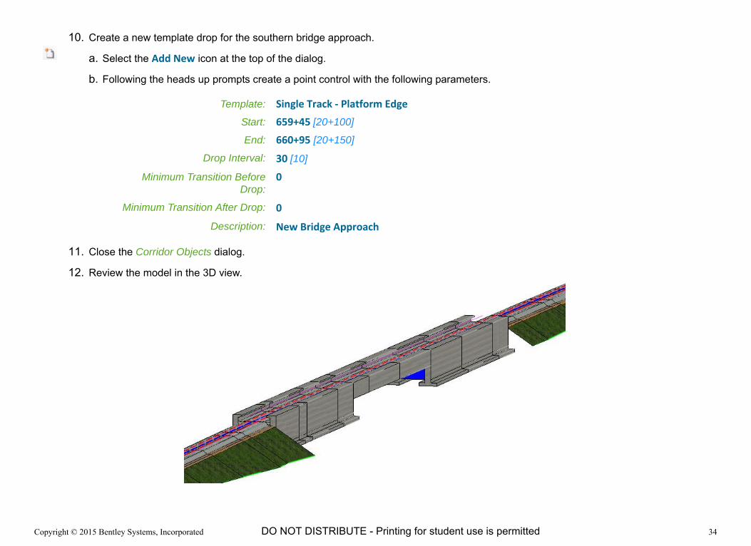
10. Create a new template drop for the southern bridge approach.
a. Select the Add New icon at the top of the dialog.
b. Following the heads up prompts create a point control with the following parameters.
11. Close the Corridor Objects dialog.
12. Review the model in the 3D view.
Template: Single Track ‐ Platform Edge
Start: 659+45 [20+100]
End: 660+95 [20+150]
Drop Interval: 30 [10]
Minimum Transition BeforeDrop:
0
Minimum Transition After Drop: 0
Description: New Bridge Approach

Copyright © 2015 Bentley Systems, Incorporated 35DO NOT DISTRIBUTE - Printing for student use is permitted
Model South Bridge Abutment
IMPORTANT: The remaining exercises in this training use two civil cells. These civil cells are stored in dgnlib file. This file must be copied to the proper folder in the workspace before using the civil cells. Copy the file Rail Training Pier and Abutment.dgnlib to the folder below. These are the default locations where the software is installed. Your software may have been installed to a different folder.
Imperial Workspace - C:\ProgramData\Bentley\PowerRailTrack V8i (SELECTseries 4)\WorkSpace\Projects\Examples\Bentley-Civil-Imperial\dgnlib\Civil_Cells
Metric Workspace - C:\ProgramData\Bentley\PowerRailTrack V8i (SELECTseries 4)\WorkSpace\Projects\Examples\Bentley-Civil-Metric\dgnlib\Civil_Cells
After copying the dgnlib file to the workspace, the Rail Track software must be exited and restarted. Remember to reload the ALG when the software is restarted.
1. Zoom View 1 and View 8 to station 657+80 [20+050] where the template transitions between the bridge approach and the south end of the bridge.

Copyright © 2015 Bentley Systems, Incorporated 36DO NOT DISTRIBUTE - Printing for student use is permitted
2. Place horizontal geometry to locate the abutment.
a. Select the Line Between Points tool from the Horizontal Geometry task menu.
b. Set the Feature Definition to Struc_Wall in the Linear > Structural folder.
c. Type South Abutment for the Name.
d. Click in View 8 to make it active.
e. Snap to the Platform Left Top feature at the end of the bridge approach.
Make sure the line is snapped to the Platform Left Top feature by ensuring the line highlights and the pop up appears as shown in the image.
f. Snap to the Platform Right Top feature at the end of the bridge approach.
Again, make sure the line is snapped to the Platform Left Top feature by ensuring the line highlights and the pop up appears as shown in the image.
The new horizontal geometry will NOT be visible in view 8 even though it was created there. View 8 is a 3D view and at this time the geometry only has a horizontal definition. If a profile is added to the geometry it would become visible in view 8.
The geometry is visible in view 1 but it may be difficult to see because of all the other graphics already located at station 657+80 [20+050].

Copyright © 2015 Bentley Systems, Incorporated 37DO NOT DISTRIBUTE - Printing for student use is permitted
3. Place abutment civil cell
a. Select the Place Civil Cell tool from the Civil Cells task menu.
b. Click the ellipsis in the tool settings window to open the Pick Civil Cell dialog.
c. Select the abutment/pier cell from the Rail Training Pier and Abutment library.
d. Click OK.
e. At the Locate Reference Element: abutment/pier (1/2) prompt, in View 1 select the South Abutment geometry created in the previous steps.
The geometry may not be easily visible but clicking at station 657+80 [20+050] in view 1 will select the horizontal geometry.

Copyright © 2015 Bentley Systems, Incorporated 38DO NOT DISTRIBUTE - Printing for student use is permitted
f. At the Locate Reference Element: Centerline (2/2) prompt select the Up Main Des geometry.
g. At the Select Elements to View Alternatives (Reset to Skip) prompt Reset (right mouse click).
h. At the Accept Civil cell Placement prompt Data to accept and create the civil cell.
4. Zoom and rotate View 8 to view the abutment civil cell.
Notice that the abutment wall is shorter than necessary to come up to the bottom of the bridge. This civil cell places the top of the wall at a fixed distance below the centerline (reference element 2) elevation.

Copyright © 2015 Bentley Systems, Incorporated 39DO NOT DISTRIBUTE - Printing for student use is permitted
5. Adjust height of abutment wall.
a. Zoom View 1 in close to the abutment civil cell.
b. Select the Element Selection tool.
c. Data on the wall control geometry (solid light purple line) in the civil cell and select Open Profile Model from the context sensitive menu.
d. When prompted to Select or Open View, click in View 5.
e. Zoom out in View 5 until you see two purple lines.
The upper purple line with the solid dot is the control and is at the elevation of the Up Main Des centerline. The lower purple line is top of the wall.
f. Select the lower purple line.
Rules appear that define the relationship between the two lines.
g. Click the ‐6.562 [-2.0] text in the middle. This is the vertical offset between the two lines.
h. Type ‐5.64 [-1.72] and press Enter.
The wall elevation is adjusted and immediately updated in the model. This should be visible in view 8.

Copyright © 2015 Bentley Systems, Incorporated 40DO NOT DISTRIBUTE - Printing for student use is permitted
Model Rails
For a more realistic visualization the rails can be added to the model.
1. Create a new corridor along the Up Main Design geometry for the rails using the following parameters.
Profile: Active Profile
Corridor Name: Rails
Template: Rails for Visualizationfrom the Rail > Tunnels, Platforms,& Misc folder
Start: 642+55 [19+585]
End: Press Alt key to lock to end station
Drop Interval: 30 [10]
Minimum Transition Before Drop: 0
Minimum Transition After Drop: 0
Description: Rails

Copyright © 2015 Bentley Systems, Incorporated 41DO NOT DISTRIBUTE - Printing for student use is permitted
2. Create a new point control to add cant to the rails.
a. In View 1 zoom to view the corridors. Zoom close enough to easily select the rail corridor.
b. Select the Rail corridor and from the context sensitive menu select the Corridor Objects tool.
c. In the Corridor Objects dialog, select Point Control.
d. Select the Add New icon at the top of the dialog to add a new point control.
e. Following the heads up prompts create a point control with the following parameters.
Start: 642+55 [19+585]
End: Press Alt key to lock to end station
Control Description: Rail Cant
Mode: Vertical
Control Type: Cant
Cant Centre Point: C cant
Cant Left Point: L cant
Cant Right Point: R cant
Locate Plan or Profile Element Select the Up Main Des geometry Hint: Use the pop up information when the cursor is hovering over a graphic to verify it is the correct geometry.
Priority: 1

Copyright © 2015 Bentley Systems, Incorporated 42DO NOT DISTRIBUTE - Printing for student use is permitted
3. Review the final model.
Note: The Rail_Center, Rail_Cant, and z - Construction levels have been turned off in this final view so the geometry lines are not visible.

Copyright © 2015 Bentley Systems, Incorporated 43DO NOT DISTRIBUTE - Printing for student use is permitted
Optional - Model North Bridge Abutment
1. Model the north bridge abutment using the same methods as the south abutment.
Can you model and abutment with wing walls? Instead of a single linear geometry element create three elements in the shape of the wing wall and complex them together.
2. Abutments could also be modeled where the rail corridor and bridge approach meet. This image shows a simple constant height abutment all perpendicular to the rail. The abutment could also have a sloped or stepped top or instead of the wing walls being perpendicular to the rail, they could sweep back at a 45 degree angle.