RAIL DRILL TYPE LD-1PY-ECO
18
This manual is the property of Cembre. Any reproduction (in full or in part) is forbidden without the prior written permission of Cembre. Cembre reserve the right to modify the specifications in this manual without prior notice. Cembre Ltd. Dunton Park Kingsbury Road, Curdworth - Sutton Coldfield West Midlands B76 9EB (Great Britain) Tel.: 01675 470440 - Fax: 01675 470220 E-mail: [email protected] www.cembre.co.uk Cembre S.p.A. Via Serenissima, 9 25135 Brescia (Italia) Telefono: 030 36921 Telefax: 030 3365766 E-mail: [email protected] www.cembre.it Cembre S.a.r.l. 22 Avenue Ferdinand de Lesseps 91420 Morangis (France) Tél.: 01 60 49 11 90 - Fax: 01 60 49 29 10 B.P. 37 - 91421 Morangis Cédex E-mail: [email protected] www.cembre.fr Cembre España S.L. Calle Verano, 6 y 8 - P.I. Las Monjas 28850 Torrejón de Ardoz - Madrid (España) Teléfono: 91 4852580 Telefax: 91 4852581 E-mail: [email protected] www.cembre.es Cembre AS Fossnes Senter N-3160 Stokke (Norway) Phone: (47) 33361765 Telefax: (47) 33361766 E-mail: [email protected] www.cembre.no Cembre GmbH Heidemannstraße 166 80939 München (Deutschland) Telefon: 089/3580676 Telefax: 089/35806777 E-mail: [email protected] www.cembre.de Cembre Inc. Raritan Center Business Park 181 Fieldcrest Avenue Edison, New Jersey 08837 (USA) Tel.: (732) 225-7415 - Fax: (732) 225-7414 E-mail: [email protected] www.cembreinc.com www.cembre.com 12 M 007 U cod. 6261140 ENGLISH OPERATION AND MAINTENANCE MANUAL RAIL DRILL TYPE LD-1PY-ECO PATENTED Certified Environmental Management System Certified Quality Management System
Transcript of RAIL DRILL TYPE LD-1PY-ECO

Thi
s m
anua
l is
the
prop
erty
of
Cem
bre
.A
ny r
epro
duct
ion
(in fu
ll or
in p
art)
is fo
rbid
den
with
out t
he p
rior
writ
ten
perm
issi
on o
f C
emb
re.
Cem
bre
res
erve
the
right
to m
odify
the
spec
ifi ca
tions
in th
is m
anua
l with
out p
rior
notic
e.
Cembre Ltd.Dunton ParkKingsbury Road, Curdworth - Sutton ColdfieldWest Midlands B76 9EB (Great Britain)Tel.: 01675 470440 - Fax: 01675 470220E-mail: [email protected]
Cembre S.p.A. Via Serenissima, 9 25135 Brescia (Italia) Telefono: 030 36921Telefax: 030 3365766E-mail: [email protected]
Cembre S.a.r.l.22 Avenue Ferdinand de Lesseps91420 Morangis (France)Tél.: 01 60 49 11 90 - Fax: 01 60 49 29 10B.P. 37 - 91421 Morangis CédexE-mail: [email protected]
Cembre España S.L.Calle Verano, 6 y 8 - P.I. Las Monjas28850 Torrejón de Ardoz - Madrid (España)Teléfono: 91 4852580Telefax: 91 4852581E-mail: [email protected]
Cembre ASFossnes SenterN-3160 Stokke (Norway)Phone: (47) 33361765Telefax: (47) 33361766E-mail: [email protected]
Cembre GmbHHeidemannstraße 16680939 München (Deutschland)Telefon: 089/3580676Telefax: 089/35806777E-mail: [email protected]
Cembre Inc.Raritan Center Business Park181 Fieldcrest AvenueEdison, New Jersey 08837 (USA)Tel.: (732) 225-7415 - Fax: (732) 225-7414E-mail: [email protected]
www.cembre.com
12 M 007 U
cod.
626
1140
ENGLISH
OPERATION AND MAINTENANCE MANUAL
RAIL DRILL
TYPE LD-1PY-ECO
PATENTED
Certified EnvironmentalManagement System
Certified QualityManagement System

16. RETURN TO Cembre FOR OVERHAUL
INDEX page
Type LD-1PNY-ECO rail drill ................................................................................. 2
1. General characteristics ..................................................................................... 2
2. Accessories supplied with the LD-1PNY-ECO drill ........................................... 3
3. Accessories to be ordered separately .............................................................. 4
4. Type SR5000 cooling unit .................................................................................10
5. Spindle advancing lever ....................................................................................12
6. Preparing the drill ..............................................................................................13
7. Drill type LD-1PY-ECO ....................................................................................15
8. Drilling ...............................................................................................................19
9. Example of other rail drilling machine applications ............................................21
10. Special applications for Cembre rail drills . ......................................................21
11. Starting the engine .............................................................................................22
12. Fuel preparation ................................................................................................23
13. Storage the drill .................................................................................................24
14. Maintenance ...................................................................................................... 25
15. Warnings ...........................................................................................................29
16. Return to Cembre for overhaul ......................................................................34
Appendix “A” ............................................................................................................29
Appendix “B” ............................................................................................................30
1 34
In the case of a breakdown contact our Area Agent who will advise you on the problem and give you the necessary instructions on how to dispatch the drill to our nearest service Centre; if possible, attach a copy of the Test Certifi cate supplied by Cembre together with the drill or, if no other references are available, indicate the approximate purchase date and the drill serial number.
Ref. LD-1PNY-ECO: basic drill without clamping device (Fig. 1).
Ref. LD-1PY-ECO:(LD-1PNY-ECO + DBG-Y)basic drill complete withrailweb clamping device type DBG-Y (Fig. 2).
� WARNINGS– Before using the drill, carefully read the instructions contained in this manual. SAVE THESE INSTRUCTIONS: this manual contains important safety and operating instructions for the drill.
– STOP THE ENGINE when servicing the drill: before removing the broach cutters, spiral bits, positioning templates etc.
– During operation keep hands away from the danger zone.
– Always wear protective glasses and work gloves.
– Avoid wearing clothes which may present a risk to personal safety.
FIG. 1
FIG. 2

6001
154
6700
524
6040
421
6001
155
6001
156
6760
378
6340
612
6900
314
6650
144
6900
348
6760
222
6140
082
6001
775
6001
751
6001
756
6001
754
6340
160
6380
310
6001
150
6001
658
6001
659
6001
152
6520
422
6140
085
6001
145
6001
281
1 1 1 1 1 2 2 4 4 2 1 1 1 2 1 1 1 2 1 1 1 1 1 1 1 1
30 29 28 27 26 25 24 23 22 21 20 17 16 13 12 11 10 09 08 07 06 05 04 03 02 01
Code
N°
Item
Desc
riptio
nQt
y
171211 13 16
04050809 07
25 2026 23 212224293010
06
2728
010203
1. GENERAL CHARACTERISTICS
– Drilling capacity: ..............................................................................∅ 9/32" to 1 9/16" (with special twist drill bits: hole diameters of 9/32" to 1-1/8" on rails up to 3 1/2" thick) (with broach cutters: hole diameters of 3/4" to 1-9/16" on rails up to 2 3/4" thick)
– Speed without load: ....................................................................................n° 270 rpm
– Combustion engine:Type: ...................................... Forced air cooled, 2 cycle, horizontal shaft, single cylinderModel: ...................................................................................................KAWASAKI TJ45EDisplacement: .......................................................................................................45.4 cm3
Power (SAE J1349): ................................................................1.4 kW (1.9 hp) / 7500 rpmFuel tank capacity:..........................................................................0.24 US gal (0.9 litres)Clutch: ................................................................... centrifugal with automatic interventionStarter: ........................................................................... recoil sarter (with spring damper)Ignition: ..............................................................................solid state ignition (C.D.I. type)Spark plug: ..........................................................................NGK BPMR7A or equivalentsFuel:...................................................................2% (1:50) oil/gasoline mixture (see § 12)Fuel consumption: ................................................................... 470 g/kW.hr / 350 g/hp.hrEmissions: ........................... according to "Phase 2" EPA regulation engines class V and European Directives 97/68/EC, 2001/63/EC and 2002/88/EC
– Weight: ..............................................................................................................34.5 lbs
– Weight: with “DBG-Y” clamping device ...........................................................41.5 lbs
– Gear sump: Recommended oil: .................. MOBIL SUPER MULTIGRADE 10-30-SAE or ESSO UNIFARM 10 W 30 or equivalent
– Acoustic noise (Directive 2006/42/EC, annexe 1, point 1.7.4.2 letter u)– The weighted continuous acoustic pressure level equivalent A at the work place LpA is equal to ................................................................99.5 dB (A) – The maximum value of the weighted acoustic displacement pressure C at the work place LpCPeak is equal to .........................................116.3 dB (C) – The acoustic power level emitted by the machine LWA is equal to .............................................................................................107.6 dB (A)
– Risks due to vibration (Directive 2006/42/EC, annexe 1, point 2.2.1.1)Tests carried out in compliance with the indications contained in UNI ENV 25349 and UNI EN 28662 part 1st Standards and under operating conditions much more severe than those normally found, certify that the weighted root mean square in frequency of the acceleration the upper limbs are exposed is 4.36 m/sec2 max.F
IG. 2
8 –
“DB
G-Y
” R
AIL
WE
B C
LA
MP
ING
DE
VIC
E
33 2
Thre
aded
bus
hø
14 C
irclip
ø 10
Circ
lipSp
acer
Pin
ø 8
x 50
pin
M5
ball d
owel
M 6
x 1
8 sc
rew
Sprin
g wa
sher
M 8
x 2
5 sc
rew
ø 4
x 10
pin
ø 1,
8x35
Spl
it pi
nTD
B 6 c
lampin
g end
piec
eBl
ockin
g sid
eCl
ampin
g sup
port l
eft sh
oulde
rCl
ampin
g sup
port r
ight s
hould
erM
8 x
10
grub
scr
ewCl
ampi
ng h
andl
e kn
obBl
ockin
g le
ver
Com
pl. b
lock
ing
scre
wTh
ickne
ss
Adju
stin
g bu
shCu
p s
prin
gø
2,5
x 16
Spl
it pi
nCl
ampi
ng s
uppo
rtDr
illing
refe
renc
e pi
n

3 32
2. ACCESSORIES SUPPLIED WITH THE DRILL
13
16
17
23
21
22
24
12
11
14
15
18
19
20
242322212019181716151413
121111211111
600375360037526380330600361260030346001166649005060019416360480600117660014286001950
Item QtyDescriptionCode N°
121110090807060504030201
Air cleaner element Spark plug Handle Complete handgrip Cap Accelerator lever Carriage handle Complete spindle lever O-ring Lever release pawl Complete cooling connection Body
111111111111
Item QtyDescriptionCode N°
600120969000606001731600119828702616001146634016060013976001195600375460037556003613
Magnetic cap Screw M 4x8 Guard Lubricator Front plate Drilling spindle M8x10 grub screw Complete air valve Level gauge Reservoir+valve cap Starting handgrip Engine
2.1) Pilot bits for controlling the cooling system:for use with short broach cutters (7/8 " depth of cut)– 1 pc PPC 2 for use with long broach cutters (2 " depth of cut)– 1 pc PPL 2
2.2) Spacer, type DPE, for use with spiral bits and APE adaptor for controlling the cooling system.
2.3) Adaptor, type ARE, for external cooling, to be used with theSR5000 cooling unit.
2.4) Grub screw, M8x10 – 4 pcs for clamping cutters or bits onto spindle shaft.
2.5) Socket head cap screws, M6x16 – 4 pcs for securing positioning shoes to front plate.
2.6) Socket head cap screws, M6x25 – 4 pcs for securing special positioning shoes to front plate.
2.7) Range of tools:– 1 pc 5 mm allen key– 1 pc 6 mm allen key– 1 pc 4 mm allen key with handle– 1 pc spark plug key– 1 pc brush
2.8) 3.4 fl oz (100 ml) oil bottlefor gear sump.
(Accessories from pos. 2.1 to pos. 2.8 are included in the “Kit of accessories” havingthe code 6001904)
2.9) Type SR5000 cooling unit
31 4
3. OPTIONAL ACCESSORIES (to be ordered separately)
3.1.1) "DBG-LY" device specifi c for clamping the drill to the girder rails (for example 128 GR or GGR 118, Ri60).With the specifi c shoes allows the positioning on both sides of the rails, complete with the TDB 3 termination.
3.1) "DBG-Y" device with moving arm for clamping the drill to the rail web and track fi ttings, complete with the TDB 6 termination.This device is supplied with the drill type LD-1PY-ECO
3.1.2) "DBG-GR" device for clamping the drill in correspondance of guard rail, complete with the TDB 1 termination.This device is supplied with the drill type LD-1PYGR-ECO.
3.1.3) DBSN device for clamping the drill to fl ange rails, for use in conjunction with the MPAF rail shoes. Using this device the rail drill can remain clamped in the drilling position even when trains pass over it. The guarantee is void if parts used are not Cembre original spares.
When ordering spare parts always give the following information:- spare part code- spare part description- drilling machine model- drilling machine serial number
FIG. 27 – DRILL ASSEMBLY
10
09
08
07
06
05
04
03
02
01
TDB 6
TDB 3
TDB 1

5 30
3.3) “VAL LD” steel carrying case for accommodating the complete drill with the clamping device.22 1/2" (L) x 13 1/2" (W) x 17 1/2" (H)
3.5) "MPAU" UNIVERSAL RAIL SHOE for rail or for special applications such as drilling #20 high speed switch points (positioning not automatic).
3.5.1) "MPAU-10" UNIVERSAL SHORT RAIL SHOEfor rail or for special applications (positioning not auto-matic).
3.2) "TST 50" two stage template (to be used with specifi c DBG-AY clamp)This device enables the drilling of 150 lb and al-uminium composite contact rails from one side.Restart of work stroke: 1,97”Typical application:– Aluminium composite rail.– 150 lbs contact rail.
3.4) “VAL MPA” suitable for storage of rail shoes, cutters and accessories• 15 1/2” (L) x 13 3/4” (W) x 2 1/4” (H)
15.1) Regularly check for correct tightening (torque) of the fi xing screws of the drilling tools and positioning shoes.
15.2) Avoid pressure jolts on the advancing lever during drilling.
15.3) Always make sure that the drilling swarf is properly removed before starting to drill a new hole.
15.4) Incomplete clamping of the drill on the rail to be drilled may lead to the breakage or accelerated wear of the drilling tool and damage to the spindle shaft bearings.
15.5) If it is necessary to operate the drill without the cutter inserted, remove the locking grub screws from the spindle shaft.
15.6) Avoid leaving the SR5000 tank under pressure and exposed to sunlight for long periods of time.
15.7) Should the DBG-Y clamping device be removed, make sure that by reassembling it, the two locking screws are fi rmily fastened.
APPENDIX “A”
Factors which infl uence the number of holes that can be made according to the tool used:
– Hardness of the element to be drilled.– Thickness to be drilled.– Stability of the drill clamping and correct assembly of the drilling tool.– Suitable lubrocooling (lubrication/cooling) to keep the temperature of the tool low so as not to compromise the effi ciency of the cutting edges, whilst at the same time facilitating the removal of the swarf.– Contact time of the cutting edges of the tool with the material to be drilled; bearin mind that the faster the hole is made the greater the effi ciency.– Observance of these basic rules: 1) Commence drilling by exerting light pressure on the advancing lever, progres- sively increasing and then relaxing it when the tool is in the exit phase. 2) Avoid pressure surges and advance according to the diameter of the drilling diameter, to avoid scratching the material or damaging the cutting edges of the tool. 3) Remember that a tool with effi cient cutting edges requires a lower application pressure than one that has already made a certain number of holes. 4) When holes are made close to raised lettering on the rails, commence drilling with very light pressure until the lettering disappears, to avoid possible breakage of the tool. 5) Bear in mind that when operating on very hard rails, as in the case of quality 1100 steel, it is advisable to increase the lubrocoolant fl ow rate.
15. WARNINGS

29 6
3.5.2) "MPAF..." SPECIFIC RAIL SHOESSuitable for positioning the drill on running and guard railsEnable the automatic position of the machine onthe drilling axis (H) of each specifi c rail.
• Note: Please contact Cembre for other types of rail.
RAIL SHOES DRILLING ON GUARD RAILS
RAIL SHOES DRILLING ON RUNNING RAILS
RAIL SHOES DRILLING ON GIRDER RAILS
H
H
(*) to be used with PFA 1 arbour extension and PPL5 Pilot Bit.
100 LB ARA-B 2 1/4”112/115/119 LB RE 2 5/8”115 LB-RE-3132 3 1/32”132 LB RE 3 9/32”136 LB RE 3 1/4”
MPAF 100 LB ARA-B GRMPAF 115/119 LB RE GRMPAF 115 LB-RE-3132MPAF 132 LB-RE-3932MPAF 136 LB-RE-314
RAIL SHOE(Using DBG-GR clamp)
TYPE OF RAIL
H(inches)
128/149 LB 3”128/149 LB 2 3/4”149 LB 2 3/4”GGR 118 2 3/8”RI60/RI60N 2.87”NP4A/NP4AM 2.87”180-105 LB 2.87”
MPAF 128/149 LB GRMPAF 128/149 LB GR 234MPAF 149 LB GR 234MPAF GGR 118MPAF RI 60 NMPAF NP4AMMPAF BA9101
TYPE OF RAIL
H(inches)
RAIL SHOE(Using DBG-LY clamp and 2” depth cutters)
40 LB ASCE 3 1/16" 60 LB ASCE 3 1/16" 80 LB ASCE 2 3/16”85 LB ASCE 2 17/64”85 LB PRR 2 1/16”85 LB PS 2 15/64”90 LB ARA-A 2 9/16”90 LB ASCE 2 45/128”100 LB ARA-A 2 3/4”100 LB ARA-B 2 65/128”100 LB ASCE 2 65/128”100 LB DY 2 5/8”100 LB NYNH&H 2 39/64”100 LB RE 2 45/64”100 LB RE-HF 2 45/64”100 LB PRR 2 9/32”100 LB PS 2 31/64”105 LB DY/110 LB RE 2 43/64”112/115/119 LB RE 2 7/8”122 CB 2 7/8”127 LB DY 3 1/8”130 LB RE/HF-A 2 3/4”130 LB RE-HF 3 1/16"130 LB HF-B 3 3/8”130 LB PS 2 3/4”131 LB RE 3 1/2”132 LB RE 3 3/32”133 LB RE 3”136 LB RE 3 3/32”136 LB LE VAL 3 1/16”140 LB RE/140 PS 3”141 LB AB/ 141 LB RE 3 3/32”152 LB PS 3 3/4”155 LB PS rail 3 3/8”
MPAF 40 LB ASCEMPAF 60 LB ASCE MPAF 80 LB ASCEMPAF 85 LB ASCEMPAF 85 LB PRRMPAF 85 LB PSMPAF 90 LB ARA-AMPAF 90 LB ASCEMPAF 100 LB ARA-AMPAF 100 LB ARA-BMPAF 100 LB ASCEMPAF 100 LB DYMPAF 100 LB NHMPAF 100 LB REMPAF 100 LB RE-HFMPAF 100 LB PRRMPAF 100 LB PSMPAF 105 LB DYMPAF 115/119 LB REMPAF 122 CBMPAF 127 LB DYMMPAF 130 LB REMPAF 130 LB RE-HFMPAF 130 LB HF-BMPAF 130 LB PSMPAF 131 LB REMPAF 132 LB REMPAF 133 LB REMPAF 136 LB REMPAF 136 LB LVMMPAF 140 LB REMPAF 141 LB ABMPAF 152 LB PS *MPAF 155 LB PS *
TYPE OF RAIL
H(inches)
RAIL SHOE
13.2.6) Checking of screws– Check and re-tighten all screws where necessary.
13.3) SPECIAL MAINTENANCE OF THE DRILLThe special maintenance operations require the intervention of qualifi ed personnel only, please contact Cembre (See § 16).
13.4) STORING THE DRILL FOR LONG PERIODS– Completely empty the fuel tank.– Start the engine and let it run until it stops, so that all fuel is exhausted from the machine.– Remove the spark plug.– Pour 3-5 cm3 of oil into the cylinder.– Repeatedly pull gently on the starting rope so that the dispersion of the oil in the cylinder is achieved reinstall the spark plug.– With a clean cloth wetted with engine oil, than clean all metal parts of the machine.– Store the drilling machine in its appropriate case or in a dry environment, protecting it against accidental damage and dust.
7 28
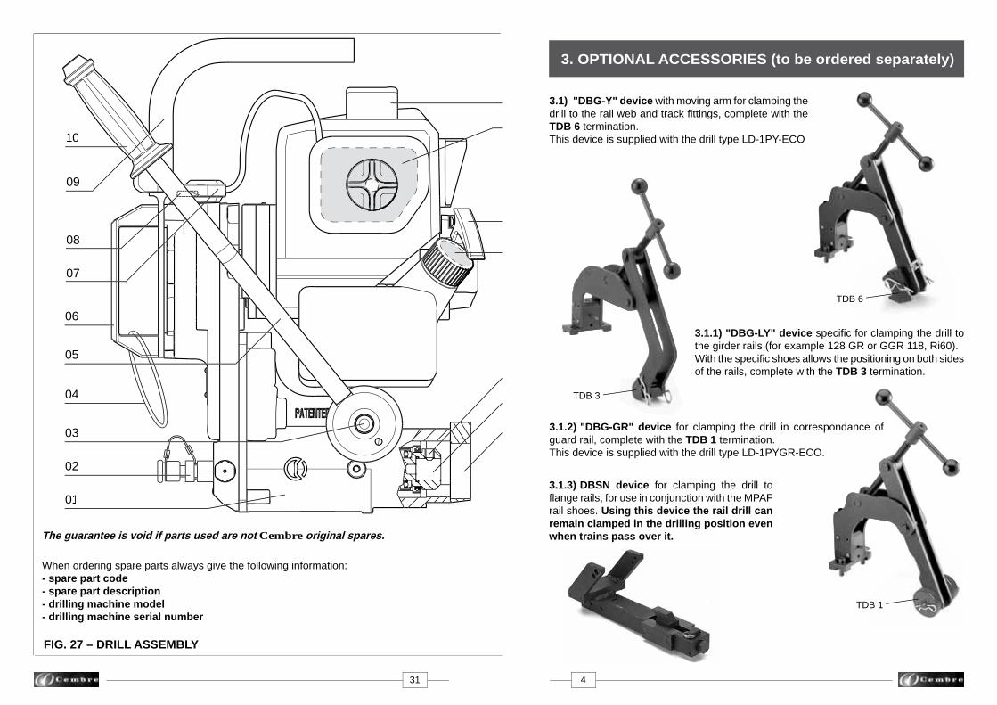
3.6) .JOINT BAR POSITIONING GAUGESPositioning gauges MRF-Y... for drilling joint bar holes at pre-defi ned distances between rail end and holes center lines.
POSITIONING GAUGE A B C
MRF Y10
MRF Y11
MRF Y12
MRF Y13
MRF Y14
MRF Y15
MRF Y16C
MRF Y10: suitable for drilling the following rails 100 ARA-B, 115 and 119 LB REMRF Y11: suitable for drilling the following rails 100 ARA-B, 105 DL&WMRF Y12: suitable for drilling the following rails 115, 119, 132, 136, 140 LB RE, 130 and 155 PSMRF Y13: suitable for drilling the following rails 80, 90 LB ASCE and 100 ARA-AMRF Y14: suitable for drilling the 85 LB ASCE railMRF Y15: suitable for drilling the 130 LB RE and 136 LE.VAL rails MRF Y: universal positioning gauge for all rail sizes
• Note: other positioning gauge sizes available upon request.
HOLES DISTANCES
A C
R
B
2 21/32" 7 1/4" 5 1/2" 3 1/2" 6" 6"
2 21/32" 7 1/4" 5 1/2"
3 1/2" 4 3/4" 4 3/4"
2 23/32" 6" 7"
3 1/2" 6" 6"
3" 6" -
2 7/16" 5" - 2 7/16" 7" - 2 3/8" 7" - 2 3/4" 6 3/4" 6 3/4"
2 11/16" 5 1/2" 5 1/2"
3 1/2" 6" 6"
FIG. 26 – SPARK PLUG CLEANING
Every 50 hours of operating
14.2.4) Spark plug cleaning (Ref. to Fig. 26)– Disconnect the spark plug lead and with a spark plug key remove the spark plug.– Clean the electrode, taking care not to damage the insulation.– Check and adjust if necessary the electrode gap (0.023 ÷ 0.027 in.).– Install and tighten the spark plug to 9 ÷ 12.5 lbf.ft, then connect the spark plug lead.– In case of plug replacement, use type NGK BPMR7A or equivalent: BOSCH WSR5F / DENSO W22MPR-U / CHAMPION RCJ6Y.
FIG. 26a – SPARK ARRESTER CLEANING
14.2.5) Spark arrester cleaning (Ref. to Fig. 26a)– Remove the spark arrester from the exhaust opening.– Clean deposits from the spark arrester screen by brushing it.– Relocate the spark arrester.
Spark arrester
Grw
R
GAUGESrilling joint bar ween rail end
RAIL END

27 8
All the broach cutters allow automatic cooling by means of the SR5000 unit supplied with the drills.
3.7) BROACH CUTTERSThese cutters rapidly produce high quality, accurate holes in a single pass. The automatic lubrocooling system reduces friction and eliminates heat build up during the drilling operation. Under standard conditions a broach cutter can drill 40-50 holes, depending on the hardness of the rail.
15128151301513215234TSC 1 1/8"15138TSC 1 1/4"TSC 1 5/16"1514415146TSC 1 1/2"TSC 3/4"0135401355013560135701358013590136001361013620136301364122183-122243-122263-122283-122303-122323-12236
BROACH CUTTER
PILOT BIT
HOLEDIAMETER
(inches)
7/8"15/16"
1"1 1/16"1 1/8" 1 3/16"1 1/4" 1 5/16"1 3/8"1 7/16"1 1/2" 3/4"7/8"
15/16“ 1“
1 1/16"1 1/8"
1 3/16“1 1/4"
1 5/16“1 3/8" 1 7/16"1 1/2" 9/16" 3/4"
13/16"7/8"
15/16"1"
1 1/8"
MAX. DEPTH OF CUT
(inches)
Ref. PPC 2
Ref. PPL 2
3-10528
2 "
7/8 "
3 "
FIG. 25 – AIR FILTER CLEANING
FIG. 24 – FUEL FILTER CLEANING
14.2.3) Air fi lter cleaning (Ref. to Fig. 25)– Manually remove the holding screws of the air cleaner cup.– Remove the fi lter element.– Wash the fi lter element in detergent and water and dry it thoroughly.– Reassemble all parts.
Operating in dusty condition may require more frequent maintenance than above.Do not operate the engine with air fi lter removed.
14.2) ROUTINE ENGINE MAINTENANCE
14.2.1) Fuel tank capA breather passage is incorporated in the tank cap. If this passage is clogged, the fuel will not fl ow into the carburetor, causing problems with starting or running the engine. At the same time, make sure that the base of the breather assembly is fi tted fi rmly into the groove inside the tank cap, as shown.
Every 20 hours of operating
14.2.2) Fuel fi lter cleaning (Ref. to Fig. 24)– Pick the grommet out of the fuel tank and remove the fuel fi lter assembly from the fuel tank together with the grommet and the fuel tube to keep dust, entering from the fuel fi lter.– Clean the fuel fi lter assembly in a bath of high fl ash-point solvent.– Dry the fuel fi lter assembly before reassemble. Improper use of solvents can result in fi re or explosion.
Tube
Grommet
Filter
Fuel tank
Transparentoverfl ow tube
Sfiato
Tappo
Serbatoio
Gancio
Membrana
Tank cap
Breather assembly
Fuel tankBreather
Breather passage

14.1.2) Removal of metal residues from the crankcase– When the drill is positioned as shown in Fig. 22c unscrew the cap with magnetic insert (24) on which any metal residues present in the oil will have collected. Carefully clean the magnetic insert with a clean cloth and screw
it back into the appropriate housing.
14.1.3) Checking of screws– Check and re-tighten all screws where necessary.
14.1.4) Lubrication (Ref. to Figs. 27 and 28)– Lubricate the spindle support housing by means of the appropriate lubricator (20), the screw of the DBG-Y clamping device.
14.1.5) Refrigeration fi lter cleaning (Ref. to Fig. 23)The refrigeration circuit of the drill is provided with anti-impurity fi lter; should an evident decrease of the fl ow of refrigeration be verifi ed, it could be necessary to clean it in the following way:– Using a14 mm key, unscrew the refrigeration coupling (02).– Extract the fi lter and clean it carefully.– Reasemble the fi lter into the coupling (02) as shown in the fi gure 23, fully tighten the coupling.
FIG. 22C – REMOVAL OF THE METALLIC WASTE
refrigeration fi lter
02
FIG. 23 – REFRIGERATION FILTER CLEANING
9 26
with adapter
3.8) SPECIAL SPIRAL TWIST BITSUsing these bits guarantees optimum performance during the drilling operations. As a rule, under normal conditions, a spiral bit can drill 70-100 holes, depending on the hard-ness of the rail.
For tools of other types, check the dimensional compatibility (particularly the size of the attachment and the length).
APED...
Diam
.
3.9) "LR 2" LUBROCOOLER CONCENTRATE, 1 or 5 gallons for optimum operation of both the broach cutters and the spiral bits.This product of vegetable origin, to be watered down in the percentage 95% water, 5% oil, will provide a white colour mixture very effective for the drilling operations resulting in no heating at the rail or the drilling machines.
3.10) "LR 3" ANTIFREEZE CONCENTRATE of 1 or 5 gallons added to the lubrocooling mixture with the right percentage will maintain the lubrocooling mixture fl uid in negative temperature consitions.
LR 3
LR 2
PE70PE95 CPE130PE160PE190PE220PE130L-ARPE3/4”-L1-ARPE7/8”-L1-ARPE1”-L1-ARPE1-1/8”-L1-ARPE1-1/4”-L1-AR
SPIRALBIT ADAPTER
HOLEDIAMETER
(inches)
9/32”3/8”1/2”5/8”3/4”7/8”1/2”3/4”7/8”1”
1 1/8”1 1/4”
SPACER
APED70APED 3/8 YAPED 130
APED135/165without adapterwithout adapter
APED 130without adapterwithout adapterwithout adapterwithout adapterwithout adapter
included in the APED 70included in the APED 3/8 Yincluded in the APED 130
included in the APED 135/165DPEDPE
included in the APED 130DPEDPEDPEDPEDPE
not requirednot requirednot requirednot requirednot requirednot required
TST50 + DBG-AYTST50 + DBG-AYTST50 + DBG-AYTST50 + DBG-AYTST50 + DBG-AYTST50 + DBG-AY
ADDITIONAL ACCESSORIES
without adapter
Diam
.
Every 50 hours of operation
24

FIG. 3 – COOLING UNIT
Detail of the max pressure valve
17 – Vent valve35 – Attachment01 – Tank complete with tube and max. pressure valve02 – Tap03 – Quick-coupling
01
14. MAINTENANCE
02
1735
03
25 10
The type SR5000 coolant unit consists of a tank complete with tube and maximum pressure valve (01), fi tted with a pump device for pressurisation, which must be connected to the attachment (35) on the drill by means of its quick-coupling (03).The delivery and shut-off of the lubrocoolant are controlled automatically, when drilling with a broach cutter, by the guide bit; when drilling with a spiral bit, delivery and shut-off of the fl uid must be effected manually by operating the tap (02). The use of the lubrocoolant supplied by Cembre, in the recommended concentrations, guaranteesoptimum use of the drilling tools.Consumption of the lubrocoolant depends both on the variable degree of opening of the tap (02) and the inner pressure of the tank: it is therefore advisable to open the tap a little when the tank is at maximum pressure, while it must be fully openedwhen the pressure in the tank is low.When using the coolant system, pay careful attention to the instructions on the tank label.
Warning:
● When the tank is not under pressure, check that the bush on the maximum pres- sure valve is screwed right down.
● To fi ll tank with lubrocoolant, turn handle anticlockwise approximately 2 turns to release handle locking mechanism. Remove handle/piston assembly from tank.
Before you service or remove parts, stop the engine and allow it to cool. Always remove the spark plug cap from spark plug when servicing the engine to prevent accidental starting.
After the fi rst 10 operating hours, proceed with oil sump change, as follows(Ref. to Fig. 22a and 22b):
– Remove the cap with the magnetic insert (24).
– Remove the oil fi ller cap (08).
– Make sure that all the oil comes out by slightly tilting
the drilling machine in order to make the operation
easier.
– Clean the cap (24) (see § 14.1.2).
– Reassemble the cap .
– Fill up the oil sump to the level indicator (see § 14.1.1)
using the oil supplied with the drilling machine; it will
be necessary to use about 100 ml.
– Replace the oil fi ller cap (08).
Ensure that disposal of used oil is in accordance with current legislation.
14.1) ORDINARY MAINTENANCE OF THE MACHINE
14.1.1) Topping up oil (Ref. to Fig. 22a and 22b)With the drill switched off and placed on a fl at surface, check the oil level in the crankcase by looking through the transparent inspection cover (16).The level must be approximately half way up the cover; if the level is low, top up the oil by unscrewing the cap (08) at the top of the crankcase and adding the quantity of oil required.
Only use the oil grade recommended in § 1.Never use regenerated or used oil.The oil must be clean.
08
16
24
FIG. 22a
FIG. 22b
�
Every 20 hours of operation
4. TYPE SR5000 COOLANT UNIT (Ref. to Fig. 3)

ARE adaptor
FIG. 5 – ARE ADAPTOR
FIG. 4
When work has been completed, put away the drill by proceeding as follows:
13.1) Depressurise the tank of the SR5000 cooling unit (see § 4), close the tap (02) on the tube from the tank, and disconnect the quick-coupling (03).
13.2) Carefully clean the drill, particularly in the spindle area, removing machining waste (swarf, etc.) and any deposits of lubricating coolant.
13.3) Fully withdraw the spindle.
13.4) Place the drill and the SR5000 cooling unit in a sealed place free from dust, moisture and the risk of accidental impact.
For better protection Cembre recommends the use of the VAL LD metal case designed for this purpose (see § 3.5). The DBG-Y moving arm device allows the drill to be housed and locked in the case. A suitable housing is also provided in this VAL LD for the VAL MPA box containing the most commonly used accessories.
13. STORAGE THE DRILL
FIG. 21STORAGE CASE
11 24
● The drill is equipped with a coolant attachment valve (35) and a vent valve (17) which are located as shown (Fig. 3). If under certain operating circumstances they need to be interchanged, proceed as follows: – Using a 17 mm hexagonal spanner unscrew the vent valve from its seat. – Using the 4 mm allen key provided with the drill, remove the appropriate coolant valve from its seat and fi t into the vent valve seat. – Fit the vent valve into the into the vacant coolant valve seat.
● When temperatures fall below 32° F (0° C) the lubrocoolant may freeze which could cause damage to the seals contained in the drill coolant system. It is therefore advisable, when storing the drilling machine, to empty the lubrocoolant system completely. Proceed as follows (Fig. 4): – Disconnect the quick coupling (03) from the coolant attachment (35) on the drilling machine. – Tilt the machine so that the coolant attachment is at its lowest point - allowing for natural drainage. – Operate the advancing lever (36) to advance and retract the drilling spindle. – Gently shake the machine to expel all fl uid.
4.1) ARE adaptorFor use with type SR5000 coolant unit. The ARE adaptor is inserted in the quick-coupling of the tank tube (ref. to Fig. 5), it may be used to provide manual external cooling when cutters are used to enlarge existing holes, or when using spiral bits not designed for automatic cooling.If necessary the ARE adaptor can also be used to clean various parts of the drill, by means of the lubrocoolant pressure jet, e.g. parts such as the tool clamping seat in the spindle shaft, seats for the fi xing screws, etc.
DRILL
VAL MPA
VAL LD
DBSN
protecpose (see § 3.5). The
d in the case. A suitable housing is acontaining the most commonly used accessories.
DRILL
VAL MPA
VAL LD
DBSN
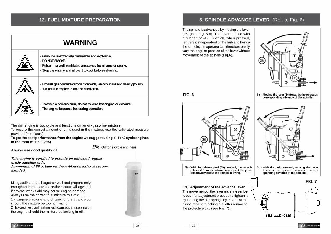
5. SPINDLE ADVANCE LEVER (Ref. to Fig. 6)
FIG. 6
The spindle is advanced by moving the lever (36) (See Fig. 6 a). The lever is fi tted with a release pawl (39) which, when pressed, renders it independent of the hub and hence the spindle; the operator can therefore easily vary the angular position of the lever without movement of the spindle (Fig.6).
FIG. 75.1) Adjustment of the advance leverThe movement of the lever must never be loose, for adjustment proceed to tighten it by loading the cup springs by means of the associated self-locking nut, after removing the protective cap (see Fig. 7).
23 12
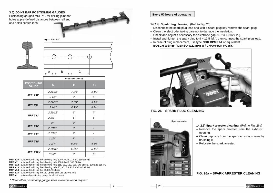
12. FUEL MIXTURE PREPARATION
6b - With the release pawl (39) pressed, the lever is released from its hub and can repeat the previ- ous travel without the spindle moving.
6c - With the hub released, moving the lever towards the operator causes a corre- sponding advance of the spindle.
6a - Moving the lever (36) towards the operator; corresponding advance of the spindle.
WARNING
- Gasoline is extremely fl ammable and explosive. - DO NOT SMOKE. - Refuel in a well ventilated area away from fl ame or sparks.- Stop the engine and allow it to cool before refueling.
- Exhaust gas contains carbon monoxide, an odourless and deadly poison. - Do not run engine in an enclosed area.
- To avoid a serious burn, do not touch a hot engine or exhaust.- The engine becomes hot during operation.
The drill engine is two cycle and functions on an oil-gasoline mixture.To ensure the correct amount of oil is used in the mixture, use the calibrated measure provided (see fi gure). To get the best performance from the engine we suggest using oil for 2 cycle engines in the ratio of 1:50 (2 %).
Always use good quality oil.
This engine is certifi ed to operate on unleaded regular grade gasoline only.A minimum of 89 octane on the antiknock index is recom-mended.
Mix gasoline and oil together well and prepare only enough for immediate use as the mixture will age and if several weeks old may cause engine damage. Always use the correct fuel mixture to avoid:1 - Engine smoking and dirtying of the spark plug should the mixture be too rich with oil.2 - Excessive overheating with consequent seizing of the engine should the mixture be lacking in oil.
2%
2% (Oil for 2 cycle engines)
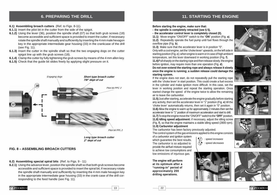
6.1) Assembling broach cutters (Ref. to Figs. 8-11).6.1.1) Insert the pilot bit in the cutter from the side of the spigot.6.1.2) Using the lever (36), position the spindle shaft (07) so that both grub screws (18) become accessible and suffi cient space is provided to insert the cutter; if necessary rotate the spindle shaft manually and suffi ciently by inserting the 4 mm male hexagon key in the appropriate intermediate gear housing (33) in the crankcase of the drill (see Fig. 11).6.1.3) Insert the cutter in the spindle shaft so that the two engaging dogs on the cutter spigot line up with the grub screws (18).6.1.4) Clamp the cutter by fully tightening the grub screws by means of the 4 mm allen key.6.1.5) Check that the guide bit slides freely by applying slight pressure on it.
FIG. 8 – ASSEMBLING BROACH CUTTERS
6.2) Assembling special spiral bits (Ref. to Figs. 9 - 11)6.2.1) Using the advance lever, position the spindle shaft so that both grub screws become accessible and suffi cient space is provided to insert the spiral bit; if necessary rotate the spindle shaft manually and suffi ciently by inserting the 4 mm male hexagon key in the appropriate intermediate gear housing (33) in the crank-case of the drill cor- responding to the feed handle (see Fig. 11).
Short type broach cutter7/8" dept of cut
Pilot bit PPC 2
Long type broach cutter2" dept of cut
Pilot bit PPL 2
Engaging dogs
07
18
13 22
6. PREPARING THE DRILL
Before starting the engine, make sure that: - the spindle is completely retracted (see § 5).- the accelerator control lever is completely closed (0).11.1) Move engine "ON/OFF" switch to the “ON” position (Fig. a).11.2) Repeatedly operate the fuel pump until fuel fl ows through the overfl ow pipe (Fig. b).11.3) Make sure that the accelerator lever is in position "0".Only with a cool engine, set the ‘choke lever’ upwards, on the left side in starting position (Fig. c); when engine is warm or in case of high ambient temperature, set this lever downward in working position (Fig. f).11.4) Pull sharply on the starting rope and then release slowly; the engine before ignition, may require more than one operation (Fig. d).Do not over-extend the starting rope and always release it slowly once the engine is running; a sudden release could damage the starting system. If the engine does not start, do not repeatedly pull the starting rope with the ‘choke lever’ in start position. This could create a fuel excess in the cylinder and make ignition more diffi cult. In this case, set the lever in working position and repeat the starting operation. Once started change the speed of the engine twice to allow the remaining air to leave the carburettor.11.5) Just after starting, accelerate the engine gradually before starting any activity, then set the accelerator lever in "1" position (Fig. e) till the ‘choke lever’ automatically returns, then set it again in "0" position.11.6) Allow the engine to warm up for approximately 2 minutes then set the accelerator lever in "1" position of maximum acceleration and start to drill. 11.7) To stop the engine move the “ON/OFF” switch to the “OFF” position.11.8) Idling speed adjustment: if necessary, adjust the idling screw (Fig. f), so that the engine maintains a stable idling speed (2800 rpm). 11.9) Carburetor adjustment The carburetor has been factory previously adjusted.The control system of the gas emissions applied to this engine consists of a carburetor and ignition system which guarantee the best results.The carburetor is so adjusted to provide the air/fuel mixture required to achieve low consumptions and low emissions of injurious gas.
The engine will perform at its optimum after a “running-in” period of approximately 200 drilling operations.
e)
: speed increases
: speed decreases d)
c)
f)
b)b)
11. STARTING THE ENGINE
a)

07
18DPE *
DPE
Bits PE ... (e.g. PE 70)
Bits PE ... (e.g. PE 220)
FIG. 11 – MANUAL SPINDLE ROTATION
FIG. 9 – ASSEMBLING THE SPIRAL TWIST BITS
FIG.10 – ASSEMBLING THE BIT-SPACER UNIT
APE ...
* use only for APE..., do not required for APED...
33
71
10. SPECIAL APPLICATIONS FOR Cembre RAIL DRILLS
* = Application developed for narrow chairs1 = For drilling 56 lb aluminium bar manufactered by FOSTER 2 = For drilling 56 lb aluminium bar manufactered by PORTER 3 = For drilling 84 lb aluminium bar manufactered by PORTER
DBG-GR over rail clamp equipped with TDB 1 termination
– Use on girder rail (Ref. to Fig. 19 a-b, example for 128 GR or GGR 118)
– Use on running rails (Ref. to Fig. 20) (narrow passage of the articulated arm)
9. EXAMPLE OF OTHER RAIL DRILL APPLICATIONS
FIG. 20
FIG. 19b – Side 2 FIG. 19a – Side 1
21 14
6.2.2) Insert into the spindle shaft, the DPE spacer required to activate the coolant system. If it necessary to use an APE... adaptor, the bit must fi rst be fi tted into the corre- sponding APE adaptor and locked with the appropriate grub screw, then the DPE spacer inserted. Note: Adaptors type APED… (e.g. APED 3/8Y) do not require use of DPE spacer.6.2.3) Insert the bit-spacer unit in the spindle shaft so that the two engaging dogs on the bit spigot line up with the grub screws. Press the bit-spacer unit home against the inner seat of the spindle: this will enable the DPE spacer to open the coolant circuit (see Fig. 10).6.2.4) Clamp the bit by fully tightening the two grub screws (18) using the 4 mm male allen key.
DBG-LY over rail clamp and the specifi c shoes (combination) allows the positioning on both sides of the rails. Use of 2" depth of cut broach cutters.

7. DRILL TYPE LD-1PY-ECO
The reference LD-1PY-ECO relates to the entire LD-1PNY-ECO drill complete with the clamping device DBG-Y for clamping it to the rail web and the track fi ttings (Ref. to Fig. 12).
The DBG-Y device consists of:– Clamping unit.– Type TDB 6 termination.– Socket head cap screws M 8x25 (2 pcs).– Spring washers (4 pcs).– Reference pin.
FIG. 12 – DRILL LD-1PY-ECO FIG. 18 – DRILLING
15 20
11
02
35
39
36
referencepin
TDB 6
M 8x25 screwsand spring washers
8.1.4) Start the engine, following instructions on § 11. 8.1.5) Proceed to drill by initially applying light pressure on the lever (36), increasing the pressure progressively, avoiding jolts, and fi nally relieving the pressure in the exit phase. When drilling close to raised markings on the rail the initial pressure must be extremely light until the markings disappear, otherwise the cutter may be damaged.8.1.6) The pilot bit will enable the lubrocoolant to be discharged throughout the drilling process.8.1.7) When drilling has been completed, fully retract the spindle, stop the engine by pressing the switch to "OFF" position, and make sure that drilling swarf is re- moved before recommencing drilling.8.1.8) After drilling it is advisable to remove with the brush all swarf from the tool and spindle area.
8.2) Drill fi tted with “long” type broach cutter (for drilling thicknesses of up to 2"). Follow the sequence described in § 8.1, taking care to position the drill on the rail by keeping the spindle fully withdrawn.

7.2) Assembly of the DBG-Y clamping device on the drill
The DBG-Y clamping device is fi tted to the front plate of the drill, centred by means of
the reference pin supplied and secured with the two socket head cap screws M 8x25 (35)
also supplied. The assembly is illustrated in Fig. 14.
FIG. 13 – ASSEMBLY OF THE TERMINATION
7.1) Assembling of the termination of the DBG-Y device with moving arm for clamping
the drill to the rail web and track fi ttings.
The termination TDB 6 of the DBG-Y device, with moving arm, have been designed for
adaptation to the different operating conditions on the rails and track fi ttings; their assembly
is shown in Fig. 13.
• When disassembling the TD termination ensure that, after removing the pivot, the
complete assembly is slid away downward without acting on the holding plate.
holding plate
FIG. 17 – DRILLING
N.B.: switch on the cooling system before starting the drill (§ 4)
8.1) Drill fi tted with “short” type broach cutter (depth of cut 7/8").The drilling sequence may be started with the drill fi tted with the broach cutter (§ 6.1),positioning jig (§ 7.2), the drill being clamped to the rail (§ 7.3), as follows:
8.1.1) Connect the female quick-coupling of the SR5000 cooling system to male coupling (35) on the drill.8.1.2) Open the tap (02) fi tted on the tank tube.8.1.3) Using the lever (36) bring the guide bit almost in contact with the rail (Fig. 17a); keeping the release pawl (39) pressed, release the lever from its cup and return it to the initial position (Fig. 17b), which will enable the travel of the lever (36) to be used in the most advantageous way.
▲!
36
39
19 16
8. DRILLING (Ref. to Figs. 17-18)
Fig. 17b Fig. 17a
Fig. 17c
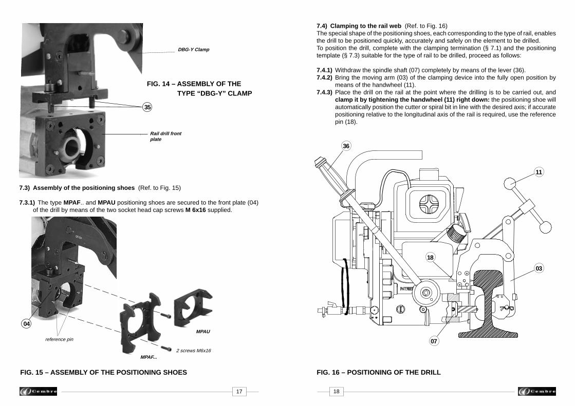
7.3) Assembly of the positioning shoes (Ref. to Fig. 15)
7.3.1) The type MPAF.. and MPAU positioning shoes are secured to the front plate (04) of the drill by means of the two socket head cap screws M 6x16 supplied.
FIG. 14 – ASSEMBLY OF THE TYPE “DBG-Y” CLAMP
DBG-Y Clamp
Rail drill front plate
35
reference pin
04
FIG. 15 – ASSEMBLY OF THE POSITIONING SHOES
2 screws M6x16MPAF...
MPAU
FIG. 16 – POSITIONING OF THE DRILL
7.4) Clamping to the rail web (Ref. to Fig. 16)The special shape of the positioning shoes, each corresponding to the type of rail, enables the drill to be positioned quickly, accurately and safely on the element to be drilled.To position the drill, complete with the clamping termination (§ 7.1) and the positioning template (§ 7.3) suitable for the type of rail to be drilled, proceed as follows:
7.4.1) Withdraw the spindle shaft (07) completely by means of the lever (36).7.4.2) Bring the moving arm (03) of the clamping device into the fully open position by means of the handwheel (11).7.4.3) Place the drill on the rail at the point where the drilling is to be carried out, and clamp it by tightening the handwheel (11) right down: the positioning shoe will automatically position the cutter or spiral bit in line with the desired axis; if accurate positioning relative to the longitudinal axis of the rail is required, use the reference pin (18).
17 18
36
11
03
07
18