Rail-DMX-DALI - Home - Artistic Licenceartisticlicence.com/WebSiteMaster/User Guides/rail-dmx...An...
24
Rail-DMX-DALI User Guide Artistic Licence Rail-DMX-DALI User Guide Version 1-7
Transcript of Rail-DMX-DALI - Home - Artistic Licenceartisticlicence.com/WebSiteMaster/User Guides/rail-dmx...An...

Rail-DMX-DALI User Guide
Artistic Licence
Rail-DMX-DALIUser Guide
Version 1-7

Page 2 Rail-DMX-DALI User Guide

Page 3 Rail-DMX-DALI User Guide
Please read these instructions before using the product.
This product has been designed & manufactured for professional use only. It should only be installed by a suitably qualified technician and in accordance with
electrical regulations in the country of use.
Unless directed in the instructions there are no user serviceable parts inside the outer case of this product.
Always disconnect from the power supply when not in use.
Any specific IP rating, where appropriate, is given in the instructions. Unless otherwise stated this product is designed for indoor use only. If used outdoors it
MUST be installed in an appropriate IP rated cabinet. Do not allow this product to be exposed to rain or moisture.
Please recycle all packaging.
Copyright © Artistic Licence Engineering Ltd. All rights reserved.
Download the user guide by scanning the following QR code:

Page 4 Rail-DMX-DALI User Guide
Reference Type Description1 LED DMX received2 LED Power3 Connection DMX Input4 Connection DMX Loop &
Termination**5 DIP Switch See table
below6 Power Input GND
Connection7 Power Input 9-24 VDC8 Connection DALI circuit
O/P 19 Connection DALI circuit
O/P 210 Connection DALI circuit
O/P 311 Connection DALI circuit
O/P 4
Dip Switch Function1 Not used2 Not used3 Mapping mode -See
Table 14 Mapping Mode - See
Table 15 Dimming curve6 Not usedMounting Diagram
Connections
** A passive loop-through connection allows onward connection to other DMX512 devices. If this feature is not required then the signal must be terminated. The product contains an internal termination resistor. This is enabled by fitting a wire link between Term and DAT+.

Page 5 Rail-DMX-DALI User Guide
DMX512, released in 1986, was created by the entertainment industry to control 512 channels of lighting fixtures per cable at near-video rates. Since then DMX has been used in the majority of lighting fixtures and, due to its qualities in fading RGB devices, has also migrated into architectural fixtures.
DALI is used mainly in commercial lighting to enable office lighting to be controlled in an intelligent and resourceful manner. It was developed to provide two-way communication between controller and ballast, providing both control and feedback of standard lighting products. The International Standard was released in 2002 and has been widely adopted.
The most common DALI device is a fluorescent ballast, around which most of its development has been concentrated. Speed has been sacrificed in favour of flexibility, ease of use and to facilitate two-way communication. This meant it has developed as a slow protocol when compared to DMX.
OverviewRail-DMX-DALI converts DMX values into DALI commands to allow integration between a DMX controller and DALI ballasts.
Up to four DALI circuits can be controlled via DMX allowing up to 256 ballasts to be connected. Simultaneous control over DALI channels, groups and scenes unlocks the flexibility of DALI.
To use Rail-DMX-DALI effectively a good understanding of both DMX and DALI is essential.
DMX512 - Digital Multiplex
DALI - Digital Addressable Lighting Interface
Converting DMX to DALIWith increasing crossover between the entertainment, architectural and commercial lighting sectors, it becomes desirable to integrate the two protocols to leverage the benefits of each. A common example is the wish to control DALI ballasts with a DMX controller that is simultaneously being used to control DMX fixtures.
Integration between DMX and DALI equipment requires careful planning as a number of issues must be considered to ensure a successful system. These include the speed
For more information about DALI, please refer to www.DALI-ag.org. A handy guide to DALI for those more familiar with DMX can be downloaded from www.ArtisticLicence.com.
Commissioning DALI ballastsUnlike DMX fixtures, DALI ballasts do not have a default start address. This is because they need unique addresses so that only one ballast replies to the controller at once. When new DALI ballasts are used they must be commissioned by being given a unique start address. This requires a DALI commissioning tool such as an Artistic Licence Dali-Scope, a hand held tool that is low cost and easy to use.
DALI Bus PSUFor DALI to transmit over a data cable there must be a separate DALI Bus PSU. This
provides a voltage on the data line which enables communication. Without this PSU the ballasts will go into a fail mode and switch on as this is considered
a fault condition. Artistic Licence offers Rail-PSU-D4, a four-bus PSU device designed to work alongside Rail-DMX-DALI, Rail-DALI-DMX and other DALI controllers.

Page 6 Rail-DMX-DALI User Guide
differences between the two protocols, the type of DALI control, dimming curves and the commissioning of fixtures.
While it is not possible to obtain cost-effectively the full sophistication of DMX-style control over a DALI ballast, with correct understanding and implementation good results can be achieved using a DALI ballast and a conversion product such as Rail-DMX-DALI.
Rail-DMX-DALI: Basics
DALI Control and SpeedThe DALI data packet comprises three parts: Address (ballast(s) being signalled), Command (what type of message is being sent) and Data (the value associated with the command). On any given circuit, DALI ballast intensity can be controlled in four ways:
1. Individual Channel level (up to 64 ballasts per circuit).
2. Group intensity (each ballast can be assigned to any of 16 groups, and can also belong to more than one group).
3. Scene selection (each ballast can store up to 16 scenes, each of which has an associated fade time).
4. Broadcast (all fixtures receive a command to respond to a given value - this is equivalent to Group when all fixtures belong to it).
DMX runs at a much higher speed than DALI and so it easily out-runs DALI. If this is not managed, a time lag appears and incoming data will start to be ignored, resulting in a step or ‘bump’ on the dimming curve. Best results are therefore achieved by sending the lowest number of commands.
Efficiency increases as one moves down the above list, so Individual Channel is the most bandwidth-hungry. Controlling individual channels can cause problems if a large number of ballasts are present due to the high number of commands that need to be sent. If this method is to be used, careful consideration should be given to the bandwidth management.
DMXTermination
Ballast 64
Ballast ...
Ballast 2
Ballast 1
Ballast ...
Ballast 2
Ballast 1
Circuit 4
Circ
uit 2
Circ
uit 3
Ballast 64
Ballast ...
Ballast 2
Ballast 1
Ballast 64
DMX Controller
Rail-DMX-DALI
Rail-PSU-D4 (DALI BUS PSU)
PSU
Circuit 1Ballast 1
Ballast 2
Ballast ...
Ballast 64
Fig. 1 - Electrical wiring diagram
Rail-DMX-DALI converts packets from a DMX controller to DALI commands, enabling control of up to four circuits of 64 DALI ballasts each.
Fig.1 below shows Rail-DMX-DALI being used to its full potential. Each of the four DALI outputs is connected to a DALI bus PSU (Rail-PSU-D4) to allow communications to the ballasts.

Page 7 Rail-DMX-DALI User Guide
DALI Routing MethodRail-DMX-DALI routes the DALI control signals via its four output circuits (Cir 1, Cir 2, Cir 3 and Cir 4) in two different ways:
y Wide (See Fig. 2 below) Each DALI circuit is controlled by a separate DMX channel (this leads to the largest DMX footprint).
y Narrow (See Fig. 3 overleaf) Equivalent entities from each circuit are controlled by a single DMX channel (this leads to the smallest DMX footprint).
In conjunction with the four basic DALI addressing modes (Channel, Group, Scene or Broadcast), this gives the user a high degree of flexibility in addressing the DALI ballasts (see Mapping Modes section).
Group 1Cir 2
DMXSlot X+16
DMXSlot X+17
DMXSlot X+63
...Group 2Cir 2
Group 16Cir 4
DALI Group Addressing in WIDE Mode
...
Group 2Cir 1
DMXSlot X+1
DMXSlot X+2
...Group 3Cir 1
...
Group 1Cir 1
DMXSlot X
DALI
DMX
Fig. 2 - DALI Routing (Wide)
An important part of DALI is discovery. This allows a controller to discover what is on a network so that only necessary commands are sent, preserving bandwidth. Rail-DMX-DALI implements this function 5 seconds after power-up and then every two minutes. If ballasts are not found on the individual channels, Rail-DMX-DALI ceases to transmit channel commands when the corresponding DMX channels change. This ensures that maximum conversion rates are achieved.
DALI Discovery Dimming CurvesThe majority of DMX devices operate using a linear dimming curve with the level selected by a decimal value between 0 and 255.
DALI works with a non-linear (exponential) curve. As the graph shows, each method produces a different output.
0
DMXDALI
0 255
100%
Ballast Power
Control Value
In its default mode of operation, Rail-DMX-DALI employs a one-to-one mapping between the DMX and DALI values, resulting in the native (exponential) dimming curve of the DALI fixture. However, Rail-DMX-DALI can also produce a linear dimming curve by setting DIP switch 5 to be ‘ON’. It should be noted that in this mode of operation, the DMX value corresponds to the percentage power level of the fixture. Therefore, any command value above 100 will simply result in 100% power level. Please refer to Dimming Curve Translation in the Appendix for more details.

Page 8 Rail-DMX-DALI User Guide
Mapping ModesAs explained previously, the DALI specification allows ballasts to be addressed as individual Channels or in Groups, Scenes or Broadcast modes. Rail-DMX-DALI provides even more control by allowing the user to connect single or multiple (up to 4) DALI circuits to the controller.
For ease of use, Rail-DMX-DALI offers four pre-programmed control modes (termed A, B, C and D), which encompass commonly encountered control scenarios. The control modes are selected using DIP switches 3 and 4 on the product, as shown in Table 1 below.
Tables 2, 3 and 4 collectively explain the relationships between the product control modes A-D, the type of DALI ballast addressing (Broadcast, Channel, Group or Scene), the implemented DALI routing method (Narrow or Wide), the slot count (in brackets) and the overall DMX footprint.
It should be noted that the DMX footprint (listed in Tables 3 and 4 under the ‘Slots’ heading’) varies between the different Modes. This is an important practical consideration as the user may need to find an acceptable compromise between control level and bandwidth.
Table 1 - DIP Switch Mode Settings
Table 2
Table 3 Broadcast Channel Group Scene
Modes Slots Modes Slots Modes Slots Modes Slots- 1 - 64 A,C 16 A,B,C,D 1
Broadcast Channel Group SceneModes Slots Modes Slots Modes Slots Modes Slots
A,B 4 C,D 256 B,D 64 A,B,C,D 4Table 4
Mode DIP Switch 3 DIP Switch 4A OFF OFFB OFF ONC ON OFFD ON ON
Mode Broadcast Channel Group Scene DMX Footprint
A W (4) - N (16) W/N (5) 25B W (4) - W (64) W/N (5) 73C - W (256) N (16) W/N (5) 277D - W (256) W (64) W/N (5) 325
Fig. 3 - DALI Routing (Narrow)
Group 1Cir 1
Group 1Cir 2
Group 1Cir 3
Group 1Cir 4
DMXSlot X
DMXSlot X+1
DMXSlot X+15
...
...
...
...
Group 2Cir 1
Group 2Cir 2
Group 2Cir 3
Group 2Cir 4
Group 16Cir 1
Group 16Cir 2
Group 16Cir 3
Group 16Cir 4
DALI
DMX
DALI Group Addressing in NARROW Mode
...
Detailed Mapping Tables for all Modes can be found in the
Appendix.

Page 9 Rail-DMX-DALI User Guide
Rail-DMX-DALI: AdvancedThe functionality of Rail-DMX-DALI can be enhanced using RDM (Remote Device Management).
In Rail-DMX-DALI there are two main uses for RDM:
y Remote Start Address Programming
y RDM Locate FunctionEach conversion channel is assigned an RDM sub-device. This allows the DMX-DALI patching to be changed. It also allows conversion options to be disabled to reduce the number of DMX channels.
There are numerous RDM programmers on the market, but generally there are two types: handheld and PC based applications.
y Handheld RDM Programmers
A good example of a handheld RDM programmer is Jump-Start. Jump-Start can be used to manually configure RDM devices and transmit DMX values. Start Address programming and RDM locate are both supported.
y Art-Net to DMX/RDM Converters
As Rail-DMX-DALI uses a high number of RDM Sub-Devices this type of control is recommended as it offers more flexibility and allows all of the data to be displayed at the same time.
A free application called DMX-Workshop can be used with this type of product. It will interrogate both an Art-Net and RDM network and display the results in a list table.
Examples of Art-Net to DMX/RDM converters available from Artistic Licence are versaSplit mini ethb-5 (desktop/truss mount) and artLynx quad (DIN rail format).
Start Address ProgrammingRail-DMX-DALI can use either 25 (Mode A), 73 (Mode B), 277 (Mode C) or 325 (Mode D) DMX channels (see Appendix).
Using an Art-Net to DMX/RDM converter and DMX-Workshop, all the sub-devices present for each conversion channel can be viewed. The screen shot below demonstrates this for Mode A.
Rail-DMX-DALI default values are set so that the conversion channels are mapped sequentially in the order of broadcast, channels, groups and scenes.
There are three types of Start Addressing:
1. Global - Sets the start address of the root device and all proceeding sub-devices are readdressed sequentially. This will override any previous changes.Right-click on the Rail-DMX-DALI main entry and select ‘Set DMX512 Start Address’.
2. Conversion Method - Sets the first start address of the control method (Channels, Group or Scenes) and readdresses all following channels sequentially. Right-click on the appropriate main sub-device for the conversion method and select ‘Set DMX512 Start Address.’ In this example,
1
2
3

Page 10 Rail-DMX-DALI User Guide
Sub-Device 1 controls Channels, Sub-Device 5 controls Groups and Sub-Device 21 controls Scenes.
To disable a conversion method, the main sub-device for that cluster of sub-devices must be set to 512. For example, to disable the Group conversions Sub-Device 5 should be given the start address of 512. The remaining start addresses of the sub-devices in that group will not change, however the conversion will be disabled.
3. Individual Control Channel - Each address can be changed independently of other channels. Right Click on any of the Sub-Devices and select ‘Set DMX512 Start Address.’
The Appendix Tables include a column entitled ‘RDM Sub-Device’ which details the above settings.
RDM locate allows a fixture to be identified, aiding remote configuration. It is often used when setting start addresses. When an RDM locate command is sent to Rail-DMX-DALI for a particular sub-device the corresponding DALI ballast will flash.
RDM Locate
Appendix
y Mode A has a DMX footprint of 25. It provides the most limited control over the DALI fixtures.
y Mode B has a DMX footprint of 73.
y Mode C has a DMX footprint of 277.
y Mode D has a DMX footprint of 325. It provides the maximum control over the DALI fixtures.
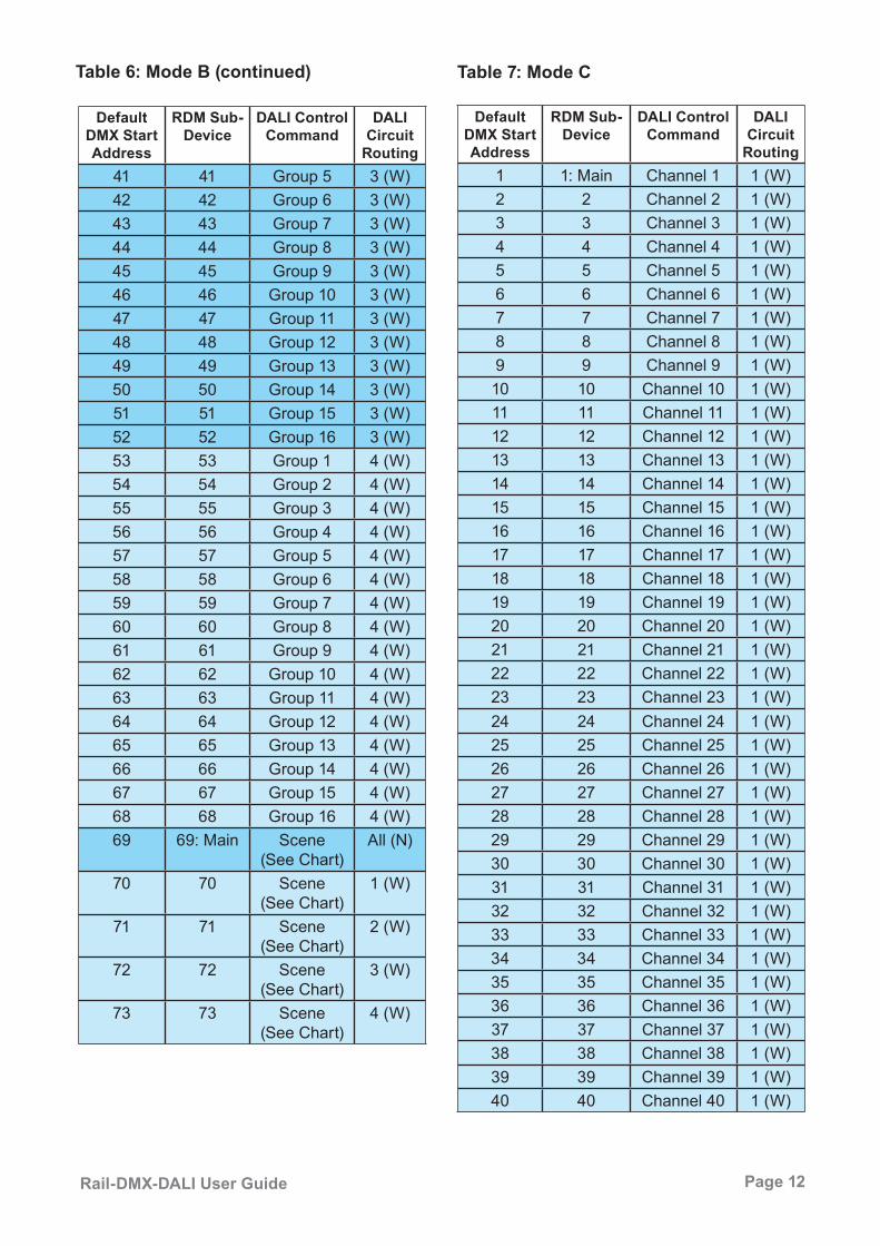
Mapping Tables (pages 11-19)To clarify the relationship between the DMX control channels and the DALI output circuits, the default assignments for each of the Modes A-D are listed in Tables 5-8 in the following pages.
The DALI Circuit Routing column gives the output circuit number and the Narrow or Wide classification (N or W) discussed earlier in ‘DALI Routing Method’.
The Appendix consists of 3 sections:
Scene Control (page 20)This section explains how Scenes are selected according to DMX value. It is referred to in the Mapping Tables.
Dimming Curve Translation (pages 20-21)This section details the function of DIP Switch 5.

Page 11 Rail-DMX-DALI User Guide
Default DMX Start Address
RDM Sub-Device
DALI Control Command
DALI Circuit
Routing1 1: Main Broadcast 1 (W)2 2 Broadcast 2 (W)3 3 Broadcast 3 (W)4 4 Broadcast 4 (W)5 5: Main Group 1 All (N)6 6 Group 2 All (N)7 7 Group 3 All (N)8 8 Group 4 All (N)9 9 Group 5 All (N)10 10 Group 6 All (N)11 11 Group 7 All (N)12 12 Group 8 All (N)13 13 Group 9 All (N)14 14 Group 10 All (N)15 15 Group 11 All (N)16 16 Group 12 All (N)17 17 Group 13 All (N)18 18 Group 14 All (N)19 19 Group 15 All (N)20 20 Group 16 All (N)21 21: Main Scene
(See Chart)All (N)
22 22 Scene (See Chart)
1 (W)
23 23 Scene (See Chart)
2 (W)
24 24 Scene (See Chart)
3 (W)
25 25 Scene (See Chart)
4 (W)
Mapping Tables
Table 5: Mode A Table 6: Mode B
Default DMX Start Address
RDM Sub-Device
DALI Control Command
DALI Circuit
Routing1 1: Main Broadcast 1 (W)2 2 Broadcast 2 (W)3 3 Broadcast 3 (W)4 4 Broadcast 4 (W)5 5: Main Group 1 1 (W)6 6 Group 2 1 (W)7 7 Group 3 1 (W)8 8 Group 4 1 (W)9 9 Group 5 1 (W)10 10 Group 6 1 (W)11 11 Group 7 1 (W)12 12 Group 8 1 (W)13 13 Group 9 1 (W)14 14 Group 10 1 (W)15 15 Group 11 1 (W)16 16 Group 12 1 (W)17 17 Group 13 1 (W)18 18 Group 14 1 (W)19 19 Group 15 1 (W)20 20 Group 16 1 (W)21 21 Group 1 2 (W)22 22 Group 2 2 (W)23 23 Group 3 2 (W)24 24 Group 4 2 (W)25 25 Group 5 2 (W)26 26 Group 6 2 (W)27 27 Group 7 2 (W)28 28 Group 8 2 (W)29 29 Group 9 2 (W)30 30 Group 10 2 (W)31 31 Group 11 2 (W)32 32 Group 12 2 (W)33 33 Group 13 2 (W)34 34 Group 14 2 (W)35 35 Group 15 2 (W)36 36 Group 16 2 (W)37 37 Group 1 3 (W)38 38 Group 2 3 (W)39 39 Group 3 3 (W)40 40 Group 4 3 (W)
Page 12 Rail-DMX-DALI User Guide
Default DMX Start Address
RDM Sub-Device
DALI Control Command
DALI Circuit
Routing41 41 Group 5 3 (W)42 42 Group 6 3 (W)43 43 Group 7 3 (W)44 44 Group 8 3 (W)45 45 Group 9 3 (W)46 46 Group 10 3 (W)47 47 Group 11 3 (W)48 48 Group 12 3 (W)49 49 Group 13 3 (W)50 50 Group 14 3 (W)51 51 Group 15 3 (W)52 52 Group 16 3 (W)53 53 Group 1 4 (W)54 54 Group 2 4 (W)55 55 Group 3 4 (W)56 56 Group 4 4 (W)57 57 Group 5 4 (W)58 58 Group 6 4 (W)59 59 Group 7 4 (W)60 60 Group 8 4 (W)61 61 Group 9 4 (W)62 62 Group 10 4 (W)63 63 Group 11 4 (W)64 64 Group 12 4 (W)65 65 Group 13 4 (W)66 66 Group 14 4 (W)67 67 Group 15 4 (W)68 68 Group 16 4 (W)69 69: Main Scene
(See Chart)All (N)
70 70 Scene (See Chart)
1 (W)
71 71 Scene (See Chart)
2 (W)
72 72 Scene (See Chart)
3 (W)
73 73 Scene (See Chart)
4 (W)
Table 6: Mode B (continued) Table 7: Mode C
Default DMX Start Address
RDM Sub-Device
DALI Control Command
DALI Circuit
Routing1 1: Main Channel 1 1 (W)2 2 Channel 2 1 (W)3 3 Channel 3 1 (W)4 4 Channel 4 1 (W)5 5 Channel 5 1 (W)6 6 Channel 6 1 (W)7 7 Channel 7 1 (W)8 8 Channel 8 1 (W)9 9 Channel 9 1 (W)10 10 Channel 10 1 (W)11 11 Channel 11 1 (W)12 12 Channel 12 1 (W)13 13 Channel 13 1 (W)14 14 Channel 14 1 (W)15 15 Channel 15 1 (W)16 16 Channel 16 1 (W)17 17 Channel 17 1 (W)18 18 Channel 18 1 (W)19 19 Channel 19 1 (W)20 20 Channel 20 1 (W)21 21 Channel 21 1 (W)22 22 Channel 22 1 (W)23 23 Channel 23 1 (W)24 24 Channel 24 1 (W)25 25 Channel 25 1 (W)26 26 Channel 26 1 (W)27 27 Channel 27 1 (W)28 28 Channel 28 1 (W)29 29 Channel 29 1 (W)30 30 Channel 30 1 (W)31 31 Channel 31 1 (W)32 32 Channel 32 1 (W)33 33 Channel 33 1 (W)34 34 Channel 34 1 (W)35 35 Channel 35 1 (W)36 36 Channel 36 1 (W)37 37 Channel 37 1 (W)38 38 Channel 38 1 (W)39 39 Channel 39 1 (W)40 40 Channel 40 1 (W)

Page 13 Rail-DMX-DALI User Guide
Default DMX Start Address
RDM Sub-Device
DALI Control Command
DALI Circuit
Routing41 41 Channel 41 1 (W)42 42 Channel 42 1 (W)43 43 Channel 43 1 (W)44 44 Channel 44 1 (W)45 45 Channel 45 1 (W)46 46 Channel 46 1 (W)47 47 Channel 47 1 (W)48 48 Channel 48 1 (W)49 49 Channel 49 1 (W)50 50 Channel 50 1 (W)51 51 Channel 51 1 (W)52 52 Channel 52 1 (W)53 53 Channel 53 1 (W)54 54 Channel 54 1 (W)55 55 Channel 55 1 (W)56 56 Channel 56 1 (W)57 57 Channel 57 1 (W)58 58 Channel 58 1 (W)59 59 Channel 59 1 (W)60 60 Channel 60 1 (W)61 61 Channel 61 1 (W)62 62 Channel 62 1 (W)63 63 Channel 63 1 (W)64 64 Channel 64 1 (W)65 65 Channel 1 2 (W)66 66 Channel 2 2 (W)67 67 Channel 3 2 (W)68 68 Channel 4 2 (W)69 69 Channel 5 2 (W)70 70 Channel 6 2 (W)71 71 Channel 7 2 (W)72 72 Channel 8 2 (W)73 73 Channel 9 2 (W)74 74 Channel 10 2 (W)75 75 Channel 11 2 (W)76 76 Channel 12 2 (W)77 77 Channel 13 2 (W)78 78 Channel 14 2 (W)79 79 Channel 15 2 (W)80 80 Channel 16 2 (W)81 81 Channel 17 2 (W)
101 101 Channel 37 2 (W)102 102 Channel 38 2 (W)103 103 Channel 39 2 (W)104 104 Channel 40 2 (W)105 105 Channel 41 2 (W)106 106 Channel 42 2 (W)107 107 Channel 43 2 (W)108 108 Channel 44 2 (W)109 109 Channel 45 2 (W)110 110 Channel 46 2 (W)111 111 Channel 47 2 (W)112 112 Channel 48 2 (W)113 113 Channel 49 2 (W)114 114 Channel 50 2 (W)115 115 Channel 51 2 (W)116 116 Channel 52 2 (W)117 117 Channel 53 2 (W)118 118 Channel 54 2 (W)119 119 Channel 55 2 (W)120 120 Channel 56 2 (W)121 121 Channel 57 2 (W)122 122 Channel 58 2 (W)
Table 7: Mode C (continued)
Default DMX Start Address
RDM Sub-Device
DALI Control Command
DALI Circuit
Routing82 82 Channel 18 2 (W)83 83 Channel 19 2 (W)84 84 Channel 20 2 (W)85 85 Channel 21 2 (W)86 86 Channel 22 2 (W)87 87 Channel 23 2 (W)88 88 Channel 24 2 (W)89 89 Channel 25 2 (W)90 90 Channel 26 2 (W)91 91 Channel 27 2 (W)92 92 Channel 28 2 (W)93 93 Channel 29 2 (W)94 94 Channel 30 2 (W)95 95 Channel 31 2 (W)96 96 Channel 32 2 (W)97 97 Channel 33 2 (W)98 98 Channel 34 2 (W)99 99 Channel 35 2 (W)100 100 Channel 36 2 (W)

Page 14 Rail-DMX-DALI User Guide
151 151 Channel 23 3 (W)152 152 Channel 24 3 (W)153 153 Channel 25 3 (W)154 154 Channel 26 3 (W)155 155 Channel 27 3 (W)156 156 Channel 28 3 (W)157 157 Channel 29 3 (W)158 158 Channel 30 3 (W)159 159 Channel 31 3 (W)160 160 Channel 32 3 (W)161 161 Channel 33 3 (W)162 162 Channel 34 3 (W)163 163 Channel 35 3 (W)
123 123 Channel 59 2 (W)124 124 Channel 60 2 (W)125 125 Channel 61 2 (W)126 126 Channel 62 2 (W)127 127 Channel 63 2 (W)128 128 Channel 64 2 (W)129 129 Channel 1 3 (W)130 130 Channel 2 3 (W)131 131 Channel 3 3 (W)132 132 Channel 4 3 (W)133 133 Channel 5 3 (W)134 134 Channel 6 3 (W)135 135 Channel 7 3 (W)136 136 Channel 8 3 (W)137 137 Channel 9 3 (W)138 138 Channel 10 3 (W)139 139 Channel 11 3 (W)140 140 Channel 12 3 (W)141 141 Channel 13 3 (W)142 142 Channel 14 3 (W)143 143 Channel 15 3 (W)144 144 Channel 16 3 (W)145 145 Channel 17 3 (W)146 146 Channel 18 3 (W)147 147 Channel 19 3 (W)148 148 Channel 20 3 (W)149 149 Channel 21 3 (W)150 150 Channel 22 3 (W)
Table 7: Mode C (continued)
Default DMX Start Address
RDM Sub-Device
DALI Control Command
DALI Circuit
Routing
Default DMX Start Address
RDM Sub-Device
DALI Control Command
DALI Circuit
Routing164 164 Channel 36 3 (W)165 165 Channel 37 3 (W)166 166 Channel 38 3 (W)167 167 Channel 39 3 (W)168 168 Channel 40 3 (W)169 169 Channel 41 3 (W)170 170 Channel 42 3 (W)171 171 Channel 43 3 (W)172 172 Channel 44 3 (W)173 173 Channel 45 3 (W)174 174 Channel 46 3 (W)175 175 Channel 47 3 (W)176 176 Channel 48 3 (W)177 177 Channel 49 3 (W)178 178 Channel 50 3 (W)179 179 Channel 51 3 (W)180 180 Channel 52 3 (W)181 181 Channel 53 3 (W)182 182 Channel 54 3 (W)183 183 Channel 55 3 (W)184 184 Channel 56 3 (W)185 185 Channel 57 3 (W)186 186 Channel 58 3 (W)187 187 Channel 59 3 (W)188 188 Channel 60 3 (W)189 189 Channel 61 3 (W)190 190 Channel 62 3 (W)191 191 Channel 63 3 (W)192 192 Channel 64 3 (W)193 193 Channel 1 4 (W)194 194 Channel 2 4 (W)195 195 Channel 3 4 (W)196 196 Channel 4 4 (W)197 197 Channel 5 4 (W)198 198 Channel 6 4 (W)199 199 Channel 7 4 (W)200 200 Channel 8 4 (W)201 201 Channel 9 4 (W)202 202 Channel 10 4 (W)203 203 Channel 11 4 (W)204 204 Channel 12 4 (W)

Page 15 Rail-DMX-DALI User Guide
205 205 Channel 13 4 (W)206 206 Channel 14 4 (W)207 207 Channel 15 4 (W)208 208 Channel 16 4 (W)209 209 Channel 17 4 (W)210 210 Channel 18 4 (W)211 211 Channel 19 4 (W)212 212 Channel 20 4 (W)213 213 Channel 21 4 (W)214 214 Channel 22 4 (W)215 215 Channel 23 4 (W)216 216 Channel 24 4 (W)217 217 Channel 25 4 (W)218 218 Channel 26 4 (W)219 219 Channel 27 4 (W)220 220 Channel 28 4 (W)221 221 Channel 29 4 (W)222 222 Channel 30 4 (W)223 223 Channel 31 4 (W)224 224 Channel 32 4 (W)225 225 Channel 33 4 (W)226 226 Channel 34 4 (W)227 227 Channel 35 4 (W)228 228 Channel 36 4 (W)229 229 Channel 37 4 (W)230 230 Channel 38 4 (W)231 231 Channel 39 4 (W)232 232 Channel 40 4 (W)233 233 Channel 41 4 (W)234 234 Channel 42 4 (W)235 235 Channel 43 4 (W)236 236 Channel 44 4 (W)237 237 Channel 45 4 (W)238 238 Channel 46 4 (W)239 239 Channel 47 4 (W)240 240 Channel 48 4 (W)241 241 Channel 49 4 (W)242 242 Channel 50 4 (W)243 243 Channel 51 4 (W)244 244 Channel 52 4 (W)245 245 Channel 53 4 (W)
Default DMX Start Address
RDM Sub-Device
DALI Control Command
DALI Circuit
Routing
Default DMX Start Address
RDM Sub-Device
DALI Control Command
DALI Circuit
Routing
Table 7: Mode C (continued)
251 251 Channel 59 4 (W)252 252 Channel 60 4 (W)253 253 Channel 61 4 (W)254 254 Channel 62 4 (W)255 255 Channel 63 4 (W)256 256 Channel 64 4 (W)257 257: Main Group 1 All (N)258 258 Group 2 All (N)259 259 Group 3 All (N)260 260 Group 4 All (N)261 261 Group 5 All (N)262 262 Group 6 All (N)263 263 Group 7 All (N)264 264 Group 8 All (N)265 265 Group 9 All (N)266 266 Group 10 All (N)267 267 Group 11 All (N)268 268 Group 12 All (N)269 269 Group 13 All (N)270 270 Group 14 All (N)271 271 Group 15 All (N)272 272 Group 16 All (N)273 273: Main Scene
(See Chart)All (N)
274 274 Scene(See Chart)
1 (W)
275 275 Scene(See Chart)
2 (W)
276 276 Scene(See Chart)
3 (W)
277 277 Scene(See Chart)
4 (W)
246 246 Channel 54 4 (W)247 247 Channel 55 4 (W)248 248 Channel 56 4 (W)249 249 Channel 57 4 (W)250 250 Channel 58 4 (W)

Page 16 Rail-DMX-DALI User Guide
Default DMX Start Address
RDM Sub-Device
DALI Control Command
DALI Circuit
1 1: Main Channel 1 1 (W)2 2 Channel 2 1 (W)3 3 Channel 3 1 (W)4 4 Channel 4 1 (W)5 5 Channel 5 1 (W)6 6 Channel 6 1 (W)7 7 Channel 7 1 (W)8 8 Channel 8 1 (W)9 9 Channel 9 1 (W)10 10 Channel 10 1 (W)11 11 Channel 11 1 (W)12 12 Channel 12 1 (W)13 13 Channel 13 1 (W)14 14 Channel 14 1 (W)15 15 Channel 15 1 (W)16 16 Channel 16 1 (W)17 17 Channel 17 1 (W)18 18 Channel 18 1 (W)19 19 Channel 19 1 (W)20 20 Channel 20 1 (W)21 21 Channel 21 1 (W)22 22 Channel 22 1 (W)23 23 Channel 23 1 (W)24 24 Channel 24 1 (W)25 25 Channel 25 1 (W)26 26 Channel 26 1 (W)27 27 Channel 27 1 (W)28 28 Channel 28 1 (W)29 29 Channel 29 1 (W)30 30 Channel 30 1 (W)31 31 Channel 31 1 (W)32 32 Channel 32 1 (W)33 33 Channel 33 1 (W)34 34 Channel 34 1 (W)35 35 Channel 35 1 (W)36 36 Channel 36 1 (W)37 37 Channel 37 1 (W)38 38 Channel 38 1 (W)39 39 Channel 39 1 (W)40 40 Channel 40 1 (W)41 41 Channel 41 1 (W)
Default DMX Start Address
RDM Sub-Device
DALI Control Command
DALI Circuit
Table 8: Mode D
56 56 Channel 56 1 (W)57 57 Channel 57 1 (W)58 58 Channel 58 1 (W)59 59 Channel 59 1 (W)60 60 Channel 60 1 (W)61 61 Channel 61 1 (W)62 62 Channel 62 1 (W)63 63 Channel 63 1 (W)64 64 Channel 64 1 (W)65 65 Channel 1 2 (W)66 66 Channel 2 2 (W)67 67 Channel 3 2 (W)68 68 Channel 4 2 (W)69 69 Channel 5 2 (W)70 70 Channel 6 2 (W)71 71 Channel 7 2 (W)72 72 Channel 8 2 (W)73 73 Channel 9 2 (W)74 74 Channel 10 2 (W)75 75 Channel 11 2 (W)76 76 Channel 12 2 (W)77 77 Channel 13 2 (W)78 78 Channel 14 2 (W)79 79 Channel 15 2 (W)80 80 Channel 16 2 (W)81 81 Channel 17 2 (W)82 82 Channel 18 2 (W)
42 42 Channel 42 1 (W)43 43 Channel 43 1 (W)44 44 Channel 44 1 (W)45 45 Channel 45 1 (W)46 46 Channel 46 1 (W)47 47 Channel 47 1 (W)48 48 Channel 48 1 (W)49 49 Channel 49 1 (W)50 50 Channel 50 1 (W)51 51 Channel 51 1 (W)52 52 Channel 52 1 (W)53 53 Channel 53 1 (W)54 54 Channel 54 1 (W)55 55 Channel 55 1 (W)

Page 17 Rail-DMX-DALI User Guide
Table 8: Mode D (continued)
Default DMX Start Address
RDM Sub-Device
DALI Control Command
DALI Circuit
Default DMX Start Address
RDM Sub-Device
DALI Control Command
DALI Circuit
83 83 Channel 19 2 (W)84 84 Channel 20 2 (W)85 85 Channel 21 2 (W)86 86 Channel 22 2 (W)87 87 Channel 23 2 (W)88 88 Channel 24 2 (W)89 89 Channel 25 2 (W)90 90 Channel 26 2 (W)91 91 Channel 27 2 (W)92 92 Channel 28 2 (W)93 93 Channel 29 2 (W)94 94 Channel 30 2 (W)95 95 Channel 31 2 (W)96 96 Channel 32 2 (W)97 97 Channel 33 2 (W)98 98 Channel 34 2 (W)99 99 Channel 35 2 (W)100 100 Channel 36 2 (W)101 101 Channel 37 2 (W)102 102 Channel 38 2 (W)103 103 Channel 39 2 (W)104 104 Channel 40 2 (W)105 105 Channel 41 2 (W)106 106 Channel 42 2 (W)107 107 Channel 43 2 (W)108 108 Channel 44 2 (W)109 109 Channel 45 2 (W)110 110 Channel 46 2 (W)111 111 Channel 47 2 (W)112 112 Channel 48 2 (W)113 113 Channel 49 2 (W)114 114 Channel 50 2 (W)115 115 Channel 51 2 (W)116 116 Channel 52 2 (W)117 117 Channel 53 2 (W)118 118 Channel 54 2 (W)119 119 Channel 55 2 (W)120 120 Channel 56 2 (W)121 121 Channel 57 2 (W)122 122 Channel 58 2 (W)123 123 Channel 59 2 (W)124 124 Channel 60 2 (W)
125 125 Channel 61 2 (W)126 126 Channel 62 2 (W)127 127 Channel 63 2 (W)128 128 Channel 64 2 (W)129 129 Channel 1 3 (W)130 130 Channel 2 3 (W)131 131 Channel 3 3 (W)132 132 Channel 4 3 (W)133 133 Channel 5 3 (W)134 134 Channel 6 3 (W)135 135 Channel 7 3 (W)136 136 Channel 8 3 (W)137 137 Channel 9 3 (W)138 138 Channel 10 3 (W)139 139 Channel 11 3 (W)140 140 Channel 12 3 (W)141 141 Channel 13 3 (W)142 142 Channel 14 3 (W)143 143 Channel 15 3 (W)144 144 Channel 16 3 (W)145 145 Channel 17 3 (W)146 146 Channel 18 3 (W)147 147 Channel 19 3 (W)148 148 Channel 20 3 (W)149 149 Channel 21 3 (W)150 150 Channel 22 3 (W)151 151 Channel 23 3 (W)152 152 Channel 24 3 (W)153 153 Channel 25 3 (W)154 154 Channel 26 3 (W)155 155 Channel 27 3 (W)156 156 Channel 28 3 (W)157 157 Channel 29 3 (W)158 158 Channel 30 3 (W)159 159 Channel 31 3 (W)160 160 Channel 32 3 (W)161 161 Channel 33 3 (W)162 162 Channel 34 3 (W)163 163 Channel 35 3 (W)164 164 Channel 36 3 (W)165 165 Channel 37 3 (W)166 166 Channel 38 3 (W)

Page 18 Rail-DMX-DALI User Guide
Table 8: Mode D (continued)
Default DMX Start Address
RDM Sub-Device
DALI Control Command
DALI Circuit
Default DMX Start Address
RDM Sub-Device
DALI Control Command
DALI Circuit
167 167 Channel 39 3 (W)168 168 Channel 40 3 (W)169 169 Channel 41 3 (W)170 170 Channel 42 3 (W)171 171 Channel 43 3 (W)172 172 Channel 44 3 (W)173 173 Channel 45 3 (W)174 174 Channel 46 3 (W)175 175 Channel 47 3 (W)176 176 Channel 48 3 (W)177 177 Channel 49 3 (W)178 178 Channel 50 3 (W)179 179 Channel 51 3 (W)180 180 Channel 52 3 (W)181 181 Channel 53 3 (W)182 182 Channel 54 3 (W)183 183 Channel 55 3 (W)184 184 Channel 56 3 (W)185 185 Channel 57 3 (W)186 186 Channel 58 3 (W)187 187 Channel 59 3 (W)188 188 Channel 60 3 (W)189 189 Channel 61 3 (W)190 190 Channel 62 3 (W)191 191 Channel 63 3 (W)192 192 Channel 64 3 (W)193 193 Channel 1 4 (W)194 194 Channel 2 4 (W)195 195 Channel 3 4 (W)196 196 Channel 4 4 (W)197 197 Channel 5 4 (W)198 198 Channel 6 4 (W)199 199 Channel 7 4 (W)200 200 Channel 8 4 (W)201 201 Channel 9 4 (W)202 202 Channel 10 4 (W)203 203 Channel 11 4 (W)204 204 Channel 12 4 (W)205 205 Channel 13 4 (W)206 206 Channel 14 4 (W)207 207 Channel 15 4 (W)208 208 Channel 16 4 (W)
209 209 Channel 17 4 (W)210 210 Channel 18 4 (W)211 211 Channel 19 4 (W)212 212 Channel 20 4 (W)213 213 Channel 21 4 (W)214 214 Channel 22 4 (W)215 215 Channel 23 4 (W)216 216 Channel 24 4 (W)217 217 Channel 25 4 (W)218 218 Channel 26 4 (W)219 219 Channel 27 4 (W)220 220 Channel 28 4 (W)221 221 Channel 29 4 (W)222 222 Channel 30 4 (W)223 223 Channel 31 4 (W)224 224 Channel 32 4 (W)225 225 Channel 33 4 (W)226 226 Channel 34 4 (W)227 227 Channel 35 4 (W)228 228 Channel 36 4 (W)229 229 Channel 37 4 (W)230 230 Channel 38 4 (W)231 231 Channel 39 4 (W)232 232 Channel 40 4 (W)233 233 Channel 41 4 (W)234 234 Channel 42 4 (W)235 235 Channel 43 4 (W)236 236 Channel 44 4 (W)237 237 Channel 45 4 (W)238 238 Channel 46 4 (W)239 239 Channel 47 4 (W)240 240 Channel 48 4 (W)241 241 Channel 49 4 (W)242 242 Channel 50 4 (W)243 243 Channel 51 4 (W)244 244 Channel 52 4 (W)245 245 Channel 53 4 (W)246 246 Channel 54 4 (W)247 247 Channel 55 4 (W)248 248 Channel 56 4 (W)249 249 Channel 57 4 (W)250 250 Channel 58 4 (W)

Page 19 Rail-DMX-DALI User Guide
Table 8: Mode D (continued)
Default DMX Start Address
RDM Sub-Device
DALI Control Command
DALI Circuit
Default DMX Start Address
RDM Sub-Device
DALI Control Command
DALI Circuit
251 251 Channel 59 4 (W)252 252 Channel 60 4 (W)253 253 Channel 61 4 (W)254 254 Channel 62 4 (W)255 255 Channel 63 4 (W)256 256 Channel 64 4 (W)257 257: Main Group 1 1 (W)258 258 Group 2 1 (W)259 259 Group 3 1 (W)260 260 Group 4 1 (W)261 261 Group 5 1 (W)262 262 Group 6 1 (W)263 263 Group 7 1 (W)264 264 Group 8 1 (W)265 265 Group 9 1 (W)266 266 Group 10 1 (W)267 267 Group 11 1 (W)268 268 Group 12 1 (W)269 269 Group 13 1 (W)270 270 Group 14 1 (W)271 271 Group 15 1 (W)272 272 Group 16 1 (W)273 273 Group 1 2 (W)274 274 Group 2 2 (W)275 275 Group 3 2 (W)276 276 Group 4 2 (W)277 277 Group 5 2 (W)278 278 Group 6 2 (W)279 279 Group 7 2 (W)280 280 Group 8 2 (W)281 281 Group 9 2 (W)282 282 Group 10 2 (W)283 283 Group 11 2 (W)284 284 Group 12 2 (W)285 285 Group 13 2 (W)286 286 Group 14 2 (W)287 287 Group 15 2 (W)288 288 Group 16 2 (W)289 289 Group 1 3 (W) 290 290 Group 2 3 (W) 291 291 Group 3 3 (W) 292 292 Group 4 3 (W)
293 293 Group 5 3 (W)294 294 Group 6 3 (W)295 295 Group 7 3 (W)296 296 Group 8 3 (W)297 297 Group 9 3 (W)298 298 Group 10 3 (W)299 299 Group 11 3 (W)300 300 Group 12 3 (W)301 301 Group 13 3 (W)302 302 Group 14 3 (W)303 303 Group 15 3 (W)304 304 Group 16 3 (W)305 305 Group 1 4 (W)306 306 Group 2 4 (W)307 307 Group 3 4 (W)308 308 Group 4 4 (W)309 309 Group 5 4 (W)310 310 Group 6 4 (W)311 311 Group 7 4 (W)312 312 Group 8 4 (W)313 313 Group 9 4 (W)314 314 Group 10 4 (W)315 315 Group 11 4 (W)316 316 Group 12 4 (W)317 317 Group 13 4 (W)318 318 Group 14 4 (W)319 319 Group 15 4 (W)320 320 Group 16 4 (W)321 321: Main Scene
(See Chart)All (N)
322 322 Scene (See Chart)
1 (W)
323 323 Scene (See Chart)
2 (W)
324 324 Scene (See Chart)
3 (W)
325 325 Scene (See Chart)
4 (W)
Page 20 Rail-DMX-DALI User Guide
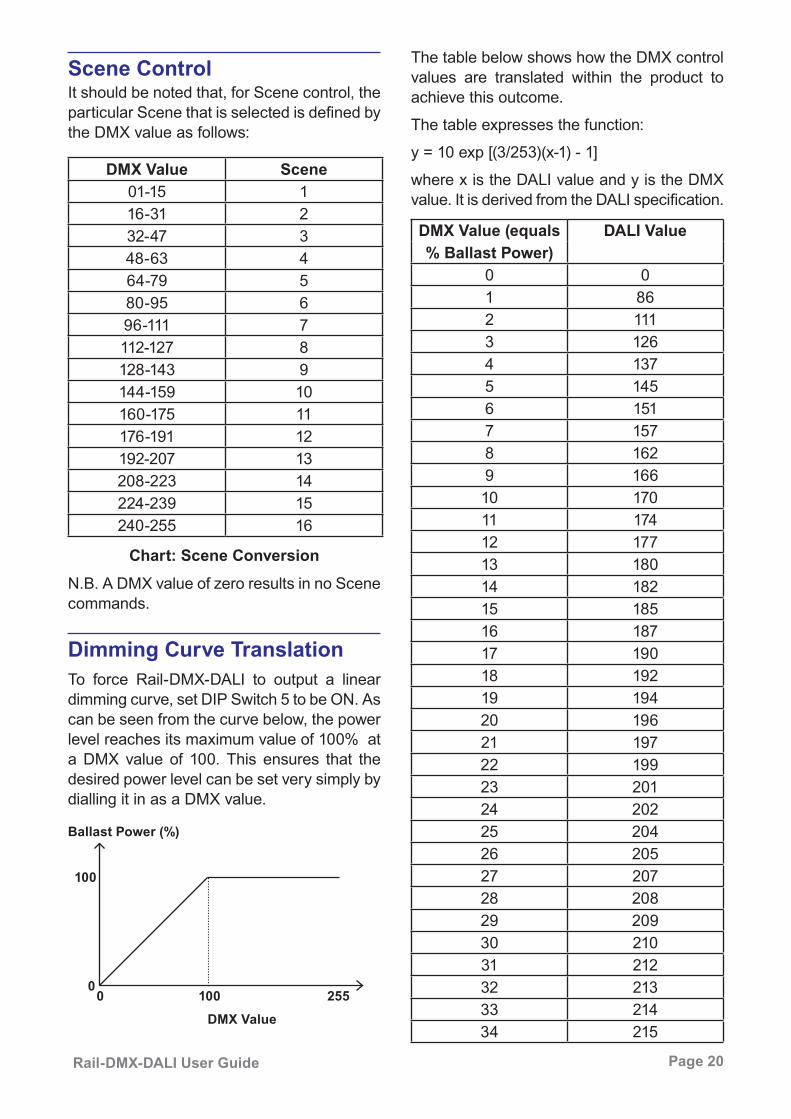
Scene ControlIt should be noted that, for Scene control, the particular Scene that is selected is defined by the DMX value as follows:
Chart: Scene ConversionN.B. A DMX value of zero results in no Scene commands.
DMX Value Scene01-15 116-31 232-47 348-63 464-79 580-95 696-111 7112-127 8128-143 9144-159 10160-175 11176-191 12192-207 13208-223 14224-239 15240-255 16
To force Rail-DMX-DALI to output a linear dimming curve, set DIP Switch 5 to be ON. As can be seen from the curve below, the power level reaches its maximum value of 100% at a DMX value of 100. This ensures that the desired power level can be set very simply by dialling it in as a DMX value.
DMX Value (equals DALI Value% Ballast Power)
0 01 862 1113 1264 1375 1456 1517 1578 1629 16610 17011 17412 17713 18014 18215 18516 18717 19018 19219 19420 19621 19722 19923 20124 20225 20426 20527 20728 20829 20930 21031 21232 21333 21434 215
Dimming Curve Translation
Ballast Power (%)
100
0100 255
DMX Value0
The table below shows how the DMX control values are translated within the product to achieve this outcome.
The table expresses the function:
y = 10 exp [(3/253)(x-1) - 1]
where x is the DALI value and y is the DMX value. It is derived from the DALI specification.

Page 21 Rail-DMX-DALI User Guide
DMX Value (equals DALI Value% Ballast Power)
35 21636 21737 21838 21939 22040 22141 22242 22343 22344 22445 22546 22647 22748 22749 22850 22951 23052 23053 23154 23255 23256 23357 23458 23459 23560 23561 23662 23763 23764 23865 23866 23967 23968 24069 24070 24171 24172 24273 24274 24375 24376 244
DMX Value (equals DALI Value% Ballast Power)
77 24478 24579 24580 24681 24682 24783 24784 24885 24886 24887 24988 24989 25090 25091 25192 25193 25194 25295 25296 25397 25398 25399 254100 254
When DIP Switch 5 is OFF, the actual DMX level number is sent to the DALI
ballast.
Page 22 Rail-DMX-DALI User Guide
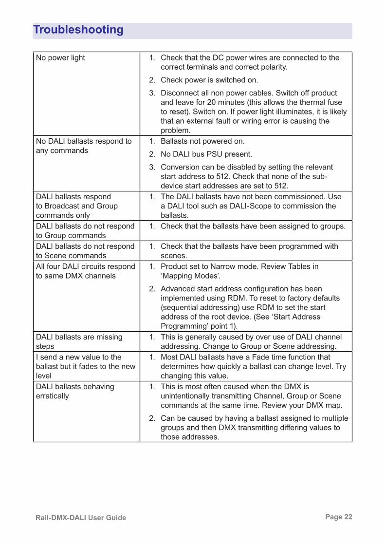
Troubleshooting
No power light 1. Check that the DC power wires are connected to the correct terminals and correct polarity.
2. Check power is switched on.3. Disconnect all non power cables. Switch off product
and leave for 20 minutes (this allows the thermal fuse to reset). Switch on. If power light illuminates, it is likely that an external fault or wiring error is causing the problem.
No DALI ballasts respond to any commands
1. Ballasts not powered on.2. No DALI bus PSU present.3. Conversion can be disabled by setting the relevant
start address to 512. Check that none of the sub-device start addresses are set to 512.
DALI ballasts respond to Broadcast and Group commands only
1. The DALI ballasts have not been commissioned. Use a DALI tool such as DALI-Scope to commission the ballasts.
DALI ballasts do not respond to Group commands
1. Check that the ballasts have been assigned to groups.
DALI ballasts do not respond to Scene commands
1. Check that the ballasts have been programmed with scenes.
All four DALI circuits respond to same DMX channels
1. Product set to Narrow mode. Review Tables in ‘Mapping Modes’.
2. Advanced start address configuration has been implemented using RDM. To reset to factory defaults (sequential addressing) use RDM to set the start address of the root device. (See ‘Start Address Programming’ point 1).
DALI ballasts are missing steps
1. This is generally caused by over use of DALI channel addressing. Change to Group or Scene addressing.
I send a new value to the ballast but it fades to the new level
1. Most DALI ballasts have a Fade time function that determines how quickly a ballast can change level. Try changing this value.
DALI ballasts behaving erratically
1. This is most often caused when the DMX is unintentionally transmitting Channel, Group or Scene commands at the same time. Review your DMX map.
2. Can be caused by having a ballast assigned to multiple groups and then DMX transmitting differing values to those addresses.

Page 23 Rail-DMX-DALI User Guide
Rail-DMX-DALI Specification
CE Compliance
Rail-DMX-DALI is CE compliant when installed in a shielded and earthed metal
case
Mechanical y Housing: DIN rail case
y Material: Lexan Plastic - UL94-V0 rated
y Overall dimensions: 90 mm (H) x 88 mm (W) x 58 mm (D)
y Weight: 0.2 kg
y Mounting: 35 mm DIN rail or surface mount
y Country of manufacture: UK Environmental
y Operating temperature: 0°C to 40°C
y Storage temperature: -10°C to +50°C
y Operating relative humidity (max): 80% non-condensing
y IP rating: IP20 indoor use only
y Certification: CE, WEEE, RoHS
y Warranty: 2-year (return to base)Power & Electrical
y Input voltage: 9-24 VDC
y Input connector: (1) 2-pin screw terminal
y Input power (max): 10 W
y Duty cycle: 80% @ 25°C
y DC fuse: internal resettable fuse for control electronics
DALI Outputs y Output mode: optically isolated
DMX512 Input y Input mode: non-isolated
y Input ESD protection: 12 kV
y Input voltage protection: +/- 80 VControl
y Input Protocols: DMX512, DMX512 (1990), DMX512-A, RDM V1.0 (E1.20 - 2006 ESTA Standard)
y Output Protocols: DALIConfiguration
y DIP Switch
y RDM configurationData Connections
y 3-pin Screw Terminal DMX Input (1 no.)
y 3-pin Screw Terminal DMX Loop (1 no.)
y 2-pin Screw Terminal DALI Outputs (4 no.)LED Indication
y Power / DMX inputPackage Contents
y Rail-DMX-DALI
y User guideOrdering Info
y Product code: Rail-DMX-DALIAccessories (not included)
y PSU-24-2-DR
y Rail-PSU-D4
y Jump-Start

WarrantyAll products are covered from date of purchase by a two year return to base warranty.
By return to base, we mean that the customer is responsible for all costs of transport to and from Artistic Licence.
Returns will not be accepted without prior authorisation. In order to discuss a request to return goods, please email:
[email protected] ComplianceAll Products manufactured or sold by Artistic Licence Engineering Ltd are fully compliant with the appropriate CE and RoHS regulations. Product specific information is available on request. Waste Electrical & Electronic Equipment (WEEE)Artistic Licence is a member of a WEEE compliance scheme and will happily recycle any of our products that you, at your expense, return to us.
Due to our policy of continuing product improvement specifications are subject to change without notice
Artistic Licence The Mould Making WorkshopSoby MewsBovey TraceyTQ13 9JGUnited Kingdom
Telephone +44 (0) 20 8863 4515
Email: [email protected]: www.ArtisticLicence.com