RADWIN 5000 HPMP - arkushplus.com.uaarkushplus.com.ua/wp-content/uploads/RW5000_UM_3-1-50.pdf ·...
278
RADWIN 5000 HPMP Point to Multipoint Broadband Wireless USER MANUAL RELEASE 3.1.50 UM 5000-3150/06.11
Transcript of RADWIN 5000 HPMP - arkushplus.com.uaarkushplus.com.ua/wp-content/uploads/RW5000_UM_3-1-50.pdf ·...

RADWIN 5000 HPMP
Point to Multipoint Broadband Wireless
USER MANUAL
RELEASE 3.1.50
UM 5000-3150/06.11
RADWIN 5000 HPMP User Manual Release 3.1.50 i
RADWIN 5000 HPMP
User Manual
Notice
This manual contains information that is proprietary to RADWIN Ltd. (RADWIN hereafter). No part of this publication may be reproduced in any form whatsoever without prior written approval by RADWIN.
Right, title and interest, all information, copyrights, patents, know-how, trade secrets and other intellectual property or other proprietary rights relating to this manual and to the RADWIN products and any software components contained therein are proprietary products of RADWIN protected under international copyright law and shall be and remain solely with RADWIN.
The RADWIN name is a registered trademark of RADWIN Ltd. No right, license, or interest to such trademark is granted hereunder, and you agree that no such right, license, or interest shall be asserted by you with respect to such trademark.
You shall not copy, reverse compile or reverse assemble all or any portion of the User Manual or any other RADWIN documentation or products. You are prohibited from, and shall not, directly or indirectly, develop, market, distribute, license, or sell any product that supports substantially similar functionality based or derived in any way from RADWIN products. Your undertaking in this paragraph shall survive the termination of this Agreement.
This Agreement is effective upon your opening of a RADWIN product package and shall continue until terminated. RADWIN may terminate this Agreement upon the breach by you of any term thereof. Upon such termination by RADWIN, you agree to return to RADWIN any RADWIN products and documentation and all copies and portions thereof.
For further information contact RADWIN at one of the addresses under Worldwide Contacts below or contact your local distributor.
Disclaimer
The parameters quoted in this document must be specifically confirmed in writing before they become applicable to any particular order or contract. RADWIN reserves the right to make alterations or amendments to the detail specification at its discretion. The publication of information in this document does not imply freedom from patent or other rights of RADWIN, or others.
Trademarks
WinLink 1000 and RADWIN 2000 are trademarks of RADWIN Ltd.
Windows 2000, XP Pro, Vista, Windows 7 and Internet Explorer are trademarks of Microsoft Inc.
Mozilla and Firefox are trademarks of the Mozilla Foundation.
Other product names are trademarks of their respective manufacturers.

RADWIN 5000 HPMP User Manual Release 3.1.50 ii
RADWIN Worldwide Offices
Corporate and EMEA Regional Headquarters
Corporate and EMEA Headquarters27 Habarzel StreetTel Aviv, 69710IsraelTel: +972.3.766.2900Fax: +972.3.766.2902Email: [email protected]
North America Regional Headquarters900 Corporate DriveMahwah, NJ, 07430USATel: +1-877-RADWIN US (+1-877 723-9468)Tel: +1-201-252-4224Fax: +1-201-621-8911Email: [email protected] Support - North America:Hours: 9 am - 6 pm EST (Mon - Fri)Email: [email protected]
APAC Regional Headquarters53A, Grange Road #15-02Spring Grove ,249566SingaporeTel: +65.6638.7864Email: [email protected]
RADWIN Regional Offices
RADWIN BrazilAv. Chucri Zaidan, 920 – 9ºSão Paulo, 04583-904BrazilTel: +55.11.3048-4110Email: [email protected]
RADWIN MexicoQuinto #20 Col El CentinelaMexico, DF, O4450MexicoTel: +52 (55) 5689 8970Email: [email protected]
RADWIN PeruAv. Antares 213Lima, 33PeruTel: +511.6285105Fax: +511-990304095Email: [email protected]
RADWIN IndiaE-13,B-1 Extn., Mohan Co-operative Industrial EstateNew Delhi, 110 044IndiaTel: +91-11-40539178Email: [email protected]
RADWIN Philippines5 Bur Bank St.Laguna, Belair, Santa RosaLaguna Philippines Tel: +63 928 7668230Email: [email protected]
RADWIN South AfricaP.O. Box 3554, Rivonia Johannesburg ,2128South AfricaTel: +27 (0)82 551 5600Email: [email protected]
RADWIN Italy and SpainPiazza Arenella 7/HNapoli ,80128Italy Tel:+390815564116Fax: +39335433620Email: [email protected]
RADWIN Central AmericaCalle La Cañada # 108-EJardines de la HaciendaCiudad Merliot El SalvadorTel: +503 2278-5628Email: [email protected]
RADWIN South East AsiaAll Season Mansion87/38 Wireless Road LumpineeBangkok ,10330ThailandTel: +66811707503Email: [email protected]

RADWIN 5000 HPMP User Manual Release 3.1.50 iii
Regulatory ComplianceGeneral NoteThis system has achieved Type Approval in various countries around the world. This means that the system has been tested against various local technical regulations and found to comply. The frequency bands in which the system operates may be “unlicensed” and in these bands, the system can be used provided it does not cause interference.
FCC - ComplianceThis equipment has been tested and found to comply with the limits for a Class B digital device, pursuant to Part 15 of the FCC Rules. These limits are designed to provide reasonable protection against harmful interference in a residential installation. This equipment generates, uses and can radiate radio frequency energy and, if not installed and used in accordance with the instructions, may cause harmful interference to radio communications. However, there is no guarantee that interference will not occur in a particular installation. If this equipment does cause harmful interference to radio or television reception, which can be determined by turning the equipment off and on, the user is encouraged to try to correct the interference by one or more of the following measures:
• Reorient or relocate the receiving antenna.
• Increase the separation between the equipment and receiver.• Connect the equipment into an outlet on a circuit different from that to which the
receiver is connected.
Consult the dealer or an experienced radio/TV technician for help.
Changes or modifications to this equipment not expressly approved by the party responsible for compliance could void the user's authority to operate the equipment.
Warning
It is the responsibility of the installer to ensure that when using the outdoor antenna kits in the United States (or where FCC rules apply), only those antennas certified with the product are used. The use of any antenna other than those certified with the product is expressly forbidden by FCC rules 47 CFR part 15.204.
Warning
It is the responsibility of the installer to ensure that when configuring the radio in the United States (or where FCC rules apply), the Tx power is set according to the values for which the product is certified. The use of Tx power values other than those, for which the product is certified, is expressly forbidden by FCC rules 47 CFR part 15.204.
Caution
Outdoor units and antennas should be installed ONLY by experienced installation professionals who are familiar with local building and safety codes and, wherever applicable, are licensed by the appropriate government regulatory authorities. Failure to do so may void the product warranty and may expose the end user or the service provider to legal and financial liabilities. Resellers or distributors of this equipment are not liable for injury, damage or violation of regulations associated with the installation of outdoor units or antennas. The installer should configure the output power level of antennas according to country regulations and antenna type.

RADWIN 5000 HPMP User Manual Release 3.1.50 iv
Indoor Units comply with part 15 of the FCC rules. Operation is subject to the following two conditions:
(1) These devices may not cause harmful interference.
(2) These devices must accept any interference received, including interference that may cause undesired operation.
Canadian Emission Requirements for Indoor UnitsThis Class B digital apparatus complies with Canadian ICES-003.
Cet appareil numẻrique de la classe B est conforme ả la norme NMB-003 du Canada.
China MIIOperation of the equipment is only allowed under China MII 5.8GHz band regulation configuration with EIRP limited to 33 dBm (2 Watt).
India WPCOperation of the equipment is only allowed under India WPC GSR-38 for 5.8GHz band regulation configuration.
UnregulatedIn countries where the radio is not regulated the equipment can be operated in any regulation configuration, best results will be obtained using Universal regulation configuration.
Safety PracticesApplicable requirements of National Electrical Code (NEC), NFPA 70; and the National Electrical Safety Code, ANSI/IEEE C2, must be considered during installation.
NOTES:
1. A Primary Protector is not required to protect the exposed wiring as long as the exposed wiring length is limited to less than or equal to 140 feet, and instructions are provided to avoid exposure of wiring to accidental contact with lightning and power conductors in accordance with NEC Sections 725-54 (c) and 800-30.
In all other cases, an appropriate Listed Primary Protector must be provided. Refer to Articles 800 and 810 of the NEC for details.
2. For protection of ODU against direct lightning strikes, appropriate requirements of NFPA 780 should be considered in addition to NEC.
3. For Canada, appropriate requirements of the CEC 22.1 including Section 60 and additional requirements of CAN/CSA-B72 must be considered as applicable.
Warning
• Where Outdoor units are configurable by software to Tx power values other than those for which the product is certified, it is the responsi-bility of the Professional Installer to restrict the Tx power to the certi-fied limits.
• This product was tested with special accessories - indoor unit (IDU or PoE), FTP CAT-5e shielded cable with sealing gasket, 12 AWG grounding cable - which must be used with the unit to insure compli-ance.

RADWIN 5000 HPMP User Manual Release 3.1.50 v
BriefTable of ContentsPart 1: Basic Installation
Chapter 1 IntroductionChapter 2 Site PreparationChapter 3 Hardware Installation
Part 2: Sector InstallationChapter 4 Getting Started with the RADWIN ManagerChapter 5 Installing the Sector
Part 3: Sector ManagementChapter 6 Managing the Sector from the HBSChapter 7 Direct HSU ConfigurationChapter 8 Monitoring and Diagnostics
Part 4: Site SynchronizationChapter 9 Hub Site SynchronizationChapter 10 Using the RADWIN GSU
Part 5: Advanced Installation TopicsChapter 11 Software UpgradeChapter 12 VLAN Functionality with RADWIN 5000 HPMPChapter 13 FCC/IC DFS Considerations
Part 6: Field Installation TopicsChapter 14 Pole and Wall InstallationChapter 15 Lightning Protection and Grounding GuidelinesChapter 16 Link Budget Calculator
Part 7: Product ReferenceAppendix A Technical SpecificationsAppendix B Wiring SpecificationsAppendix C MIB ReferenceAppendix D RF ExposureAppendix E Setting Antenna ParametersAppendix F Regional Notice: French Canadian
Index

RADWIN 5000 HPMP User Manual Release 3.1.50 vi
FullTable of ContentsPart 1: Basic Installation
Chapter 1 Introduction Welcome to RADWIN 5000 HPMP!...............................................................1-1RADWIN 5000 HPMP Highlights....................................................................1-1What’s New in Release 3.1.50 ......................................................................1-1Some Terminology ......................................................................................1-2
Key features of RADWIN 5000 HPMP ............................................................1-2RADWIN 5000 HPMP Components ...............................................................1-3
RADWIN 5000 HBS High Capacity Base Station ................................................1-3RADWIN 55xx HSU High Capacity Subscriber Units...........................................1-3
The RADWIN Manager.................................................................................1-4Conventions Used in this Manual ..................................................................1-4
Notifications ............................................................................................1-4Typographical conventions .........................................................................1-4
General .........................................................................................................1-4Software .......................................................................................................1-4
Viewing and Printing .................................................................................1-5Chapter 2 Site Preparation
Planning the Sector Site...............................................................................2-1Overview ................................................................................................2-1
The Site Survey...........................................................................................2-1Introduction ............................................................................................2-1Recommended Equipment ..........................................................................2-1
Stage 1: Preliminary Survey .........................................................................2-2Stage 2: Physical Survey..............................................................................2-3
Additional Outdoor Site Requirements ...........................................................2-3Additional Indoor Site Requirements .............................................................2-4
Stage 3: RF Survey......................................................................................2-4RF Planning for Dense Installations and Collocated Sites ................................2-4
Chapter 3 Hardware InstallationSafety Practices...........................................................................................3-1
Preventing overexposure to RF energy ..........................................................3-1Grounding ...............................................................................................3-1Protection against Lightning .......................................................................3-2General ..................................................................................................3-2
Package Contents........................................................................................3-2HBS and HSU ODU Package Contents ...........................................................3-2External Antenna Package Contents .............................................................3-4Power Over Ethernet (PoE) Devices ..............................................................3-5
GbE PoE........................................................................................................3-5Basic PoE Device............................................................................................3-5
Hub Site Synchronization (HSS) Unit ............................................................3-6GSU .......................................................................................................3-6
Additional Tools and Materials Required ........................................................3-7Tools and Materials ...................................................................................3-7Cables and connectors ...............................................................................3-7
Hardware Installation Sequence ...................................................................3-8Outdoor installation .....................................................................................3-9
Preparing the ODU before Deployment .........................................................3-9Mounting the ODU ....................................................................................3-9Mounting external antennas ..................................................................... 3-10

RADWIN 5000 HPMP User Manual Release 3.1.50 vii
Mounting the Lightning Protection Devices .................................................. 3-10Outdoor Connections ............................................................................... 3-10Installing a Sector using PoE Devices .......................................................... 3-11Connecting User Equipment ...................................................................... 3-11
Aligning HSUs to a HBS.............................................................................. 3-11Part 2: Sector Installation
Chapter 4 Getting Started with the RADWIN ManagerWhat we will do here...................................................................................4-1Installing the RADWIN Manager Application ..................................................4-1
Minimum System Requirements ...................................................................4-1Installing the Software ..............................................................................4-2
Getting Started with the RADWIN Manager ...................................................4-2The RADWIN Manager log-on Concept..........................................................4-4Log-on Errors and Cautions..........................................................................4-6
Unsupported Device ..................................................................................4-6Incorrect IP Address .................................................................................4-7Incorrect Password ...................................................................................4-7Invalid Read/Write Community String ...........................................................4-7
Exploring the RADWIN Manager Main Window - HBS .....................................4-7HBS Main Button Menu ..............................................................................4-8Sector Status Panel ...................................................................................4-8Base Station Panel ....................................................................................4-8HBS Events Log ..................................................................................... 4-10HBS Main Window - HSUs Panel ................................................................ 4-11
Exploring the RADWIN Manager Main Window - HSU ................................... 4-13Logging on to an HSU................................................................................ 4-14
HSU Main Button Menu ............................................................................ 4-16HSU Link Status ..................................................................................... 4-16HSU Events Log ..................................................................................... 4-17HSU Link Performance ............................................................................. 4-17
Setting RADWIN Manager Preferences ........................................................ 4-17Monitor ................................................................................................ 4-18Events .................................................................................................. 4-19Advanced .............................................................................................. 4-20
What Comes Next?.................................................................................... 4-20Chapter 5 Installing the Sector
Scope of this Chapter ..................................................................................5-1Concepts ....................................................................................................5-1Workflow....................................................................................................5-2Configuring the Sector out of the Box - IP Addresses .....................................5-2Activating the HBS.......................................................................................5-7Configuring the HSUs for Service ................................................................ 5-14Registering the HSUs for Service ................................................................ 5-17Choosing Diversity Antenna Mode During Registration.................................. 5-21Deactivating the HBS................................................................................. 5-22Deregistering a HSU .................................................................................. 5-22Where has my HSU gone?.......................................................................... 5-23
Part 3: Sector ManagementChapter 6 Managing the Sector from the HBS
Scope of this Chapter ..................................................................................6-1Configuring a HBS .......................................................................................6-1
Configuration Menu Buttons .......................................................................6-1System ...................................................................................................6-2Air Interface ............................................................................................6-3Tx and Antenna .......................................................................................6-3

RADWIN 5000 HPMP User Manual Release 3.1.50 viii
Hub Site Sync [HSS] .................................................................................6-5Management ...........................................................................................6-6
Trap Destinations...........................................................................................6-7VLAN for Management ...................................................................................6-7Supported Protocols .......................................................................................6-8
Inventory ................................................................................................6-8Security ..................................................................................................6-9
Changing the Link Password .........................................................................6-10RADWIN Manager Community Strings ...........................................................6-10Editing Community Strings............................................................................6-11Forgotten Community string .........................................................................6-12
Date and Time ....................................................................................... 6-13Setting the Date and Time............................................................................6-13
Ethernet ............................................................................................... 6-15Operations ............................................................................................ 6-15
Reverting to Factory Settings ........................................................................6-16License Activation ........................................................................................6-16
Advanced .............................................................................................. 6-17DFS and False Radar Mitigation.....................................................................6-18
HSU Connection Table ............................................................................... 6-19Configuring a HSU from the HBS Main Window............................................ 6-20
Configuration Menu Buttons ..................................................................... 6-20System ................................................................................................. 6-21Tx & Antenna ........................................................................................ 6-22Management ......................................................................................... 6-23Inventory .............................................................................................. 6-24Security ................................................................................................ 6-25Date & Time .......................................................................................... 6-26Ethernet ............................................................................................... 6-27Maximum Information Rate ...................................................................... 6-27VLAN Configuration ................................................................................. 6-28Operations ............................................................................................ 6-29Advanced .............................................................................................. 6-30
Replacing a HSU........................................................................................ 6-31Updating HSU Services .............................................................................. 6-34Suspending a HSU..................................................................................... 6-35Changing the Sector Band.......................................................................... 6-36Configuration with Telnet........................................................................... 6-40
HBS ..................................................................................................... 6-40HSU ..................................................................................................... 6-43
Chapter 7 Direct HSU ConfigurationScope of this Chapter ..................................................................................7-1Configuring a HSU.......................................................................................7-1
Configuration Menu Buttons .......................................................................7-2System ...................................................................................................7-3Air Interface ............................................................................................7-4
Where has my HSU gone? ..............................................................................7-4Tx & Antenna ..........................................................................................7-6Management ...........................................................................................7-7Inventory ................................................................................................7-8Security ..................................................................................................7-9Date & Time .......................................................................................... 7-10Operations ............................................................................................ 7-11Advanced .............................................................................................. 7-12
Chapter 8 Monitoring and DiagnosticsRetrieving Link Information (Get Diagnostics)................................................8-1Throughput Checking ..................................................................................8-3

RADWIN 5000 HPMP User Manual Release 3.1.50 ix
Recent Events .............................................................................................8-4Performance Monitoring...............................................................................8-6
HBS .......................................................................................................8-7HSU .......................................................................................................8-9
From the HBS ................................................................................................8-9Direct or Over the Air ...................................................................................8-10
More on the Thresholds ........................................................................... 8-12RADWIN Manager Traps ............................................................................ 8-12Active Alarms............................................................................................ 8-13Other Diagnostic Aids ................................................................................ 8-14
Link Budget Calculator ............................................................................. 8-14Online Help ........................................................................................... 8-14Customer Support .................................................................................. 8-14
Part 4: Site SynchronizationChapter 9 Hub Site Synchronization
Scope of this Chapter ..................................................................................9-1 What is Hub Site Synchronization?...............................................................9-1Hardware Installation ..................................................................................9-3
Connecting an HSS Unit .............................................................................9-3Using a Single HSS Unit .............................................................................9-4Using More than One HSS Unit ....................................................................9-4
Condition 1: Cabling Sequence........................................................................9-4Condition 2: Total HSS Cable Length ...............................................................9-6
ODU/HSS Unit Connection Pinout .................................................................9-6Radio Frame Pattern (RFP)...........................................................................9-6
Without HSS ............................................................................................9-7RFP and HSS ...........................................................................................9-7RFP: General Radio Frame Pattern ...............................................................9-8
Sector Configuration and HSS ......................................................................9-8Chapter 10 Using the RADWIN GSU
What is it for............................................................................................. 10-1GSU Functionality ...................................................................................... 10-1Typical GSU Scenarios ............................................................................... 10-1
Independent Distributed Sites ................................................................... 10-1Multiple Distributed Sites with Communication .............................................. 10-2Cascaded Sites using Shifted Phase Transmission ......................................... 10-3
GSU Redundancy ...................................................................................... 10-3GSU Kit Contents....................................................................................... 10-4GSU Installation ........................................................................................ 10-4
Overview .............................................................................................. 10-4Preparing the GSU for Use ........................................................................ 10-5Mounting the GSU .................................................................................. 10-5Configuring the GSU ............................................................................... 10-5
Getting Started ............................................................................................10-5Using Site Configuration for the GSU .............................................................10-7
GSU Preferences .................................................................................. 10-15GSU Monitoring and Diagnostics ............................................................... 10-15GSU Telnet Support................................................................................. 10-15Software Update for GSUs........................................................................ 10-16
Part 5: Advanced Installation TopicsChapter 11 Software Upgrade
What is the Software Upgrade Utility?......................................................... 11-1Upgrading an Installed Sector .................................................................... 11-2
Chapter 12 VLAN Functionality with RADWIN 5000 HPMPVLAN Tagging - Overview .......................................................................... 12-1

RADWIN 5000 HPMP User Manual Release 3.1.50 x
VLAN Terminology .................................................................................. 12-1VLAN Background Information on the WEB .................................................. 12-1
Scope of this Chapter ................................................................................ 12-1Requirements............................................................................................ 12-1VLAN Tagging ........................................................................................... 12-1
QinQ (Double Tagging) for Service Providers ............................................... 12-2VLAN Untagging ..................................................................................... 12-3Port Functionality ................................................................................... 12-3
Ingress Direction..........................................................................................12-4Egress Direction...........................................................................................12-5
VLAN Configuration Using the RADWIN Manager ......................................... 12-5Management Traffic and Ethernet Service Separation .................................... 12-5Managing the HBS over the Air from an HSU ................................................ 12-5Configuration of VLAN Tagging for Ethernet Service ...................................... 12-6
Chapter 13 FCC/IC DFS ConsiderationsFCC 5.4GHz Device Registration ................................................................. 13-1
Registering the Device ............................................................................. 13-1TDWR Table ............................................................................................. 13-5
Part 6: Field Installation TopicsChapter 14 Pole and Wall Installation
ODU Mounting Kit Contents........................................................................ 14-1Mounting an ODU on a Pole ....................................................................... 14-2Mounting an ODU on a Wall ....................................................................... 14-3Mounting an External Antenna ................................................................... 14-4Mounting a Connectorized ODU Horizontally................................................ 14-4
Chapter 15 Lightning Protection and Grounding GuidelinesGrounding for Antenna Cable ..................................................................... 15-1Grounding for Indoor/Outdoor Units ........................................................... 15-2
ODU Grounding ...................................................................................... 15-2IDU Grounding ....................................................................................... 15-3
The RADWIN Lightning Protection Kit ......................................................... 15-3Using Lightning Protectors and Grounding................................................... 15-3Mounting RADWIN Lighting Protection unit ................................................. 15-6Internal ESD Protection circuits .................................................................. 15-7
Chapter 16 Link Budget CalculatorOverview .................................................................................................. 16-1
User Input ............................................................................................ 16-1Link Budget Calculator Internal Data .......................................................... 16-1
Calculations .............................................................................................. 16-2EIRP .................................................................................................... 16-2Expected RSS and Fade Margin ................................................................. 16-2Min and Max Range ................................................................................ 16-2Service ................................................................................................. 16-2Availability ............................................................................................ 16-2Antenna Height ...................................................................................... 16-3
About the Fresnel Zone.............................................................................. 16-3 Running the Link Budget Calculator ........................................................... 16-5
Part 7: Product ReferenceAppendix A Technical Specifications
Scope of these Specifications .......................................................................A-1ODU - HBS and HSU....................................................................................A-1GbE PoE Device - Indoor, AC for HBS only ....................................................A-3PoE Device - Indoor, AC...............................................................................A-4PoE Device - Outdoor, DC ............................................................................A-5

RADWIN 5000 HPMP User Manual Release 3.1.50 xi
GSU ...........................................................................................................A-5Antenna Characteristics ...............................................................................A-6
Appendix B Wiring SpecificationsODU-PoE Cable (HBS and HSU)....................................................................B-1HBS/HSS Unit Connection Pinout ..................................................................B-1 User Port Connectors..................................................................................B-2
LAN Port .................................................................................................B-2DC Power Terminals ....................................................................................B-2
DC PoE ...................................................................................................B-2Appendix C MIB Reference
Introduction................................................................................................C-1About the MIB .........................................................................................C-1Terminology ............................................................................................C-1
Interface API ..............................................................................................C-1Control Method ........................................................................................C-1Community String .....................................................................................C-2
Private MIB Structure ..................................................................................C-2MIB Parameters ..........................................................................................C-3
Supported Variables from the RFC 1213 MIB ..................................................C-3Private MIB Parameters .............................................................................C-5MIB Traps .............................................................................................C-27General ................................................................................................C-27Trap Parameters ....................................................................................C-28
RADWIN Manager Traps ............................................................................C-32Appendix D RF ExposureAppendix E Setting Antenna Parameters
Antenna Issues ...........................................................................................E-1About Single and Dual Antennas...................................................................E-1
Dual Antennas at the HBS and a HSU ...........................................................E-1MIMO Mode...................................................................................................E-1Diversity Mode...............................................................................................E-2
Single Antennas at Both Sites .....................................................................E-2Single at One Site, Dual Antennas at the Other ..............................................E-2
Considerations for Changing Antenna Parameters ..........................................E-3Appendix F Regional Notice: French Canadian
Procédures de sécurité ................................................................................ F-1Généralités .............................................................................................. F-1Mise à la terre ......................................................................................... F-1Protection contre la foudre ......................................................................... F-1Précautions de sécurité pendant le montage de ODU .......................................F-2Connecter la terre à IDU-C ......................................................................... F-2
Installation sur pylône et mur....................................................................... F-2Contenu du kit de montage ODU ................................................................. F-3Montage sur un pylône .............................................................................. F-3Montage sur un mur ................................................................................. F-5Montage d'une antenne externe .................................................................. F-6Contenu du kit de montage d'une antenne externe ......................................... F-6
Index
RADWIN 5000 HPMP User Manual Release 3.1.50 xii
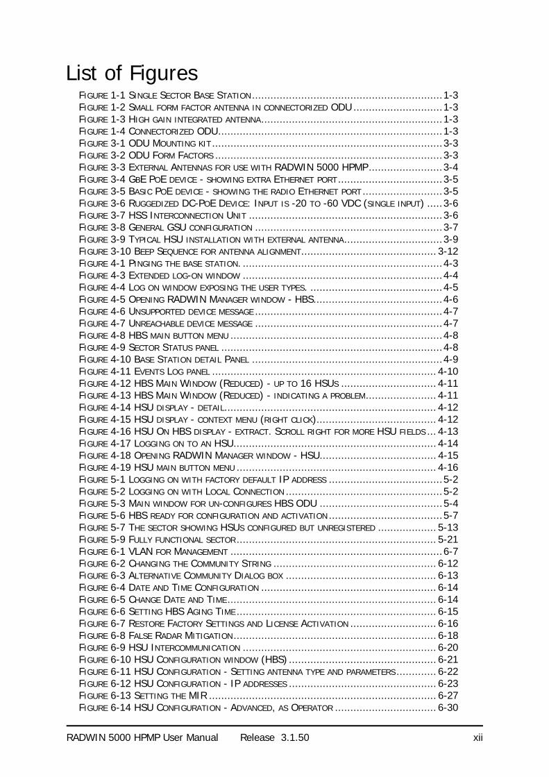
List of FiguresFIGURE 1-1 SINGLE SECTOR BASE STATION..............................................................1-3FIGURE 1-2 SMALL FORM FACTOR ANTENNA IN CONNECTORIZED ODU .............................1-3FIGURE 1-3 HIGH GAIN INTEGRATED ANTENNA...........................................................1-3FIGURE 1-4 CONNECTORIZED ODU.........................................................................1-3FIGURE 3-1 ODU MOUNTING KIT...........................................................................3-3FIGURE 3-2 ODU FORM FACTORS ..........................................................................3-3FIGURE 3-3 EXTERNAL ANTENNAS FOR USE WITH RADWIN 5000 HPMP........................3-4FIGURE 3-4 GBE POE DEVICE - SHOWING EXTRA ETHERNET PORT..................................3-5FIGURE 3-5 BASIC POE DEVICE - SHOWING THE RADIO ETHERNET PORT ..........................3-5FIGURE 3-6 RUGGEDIZED DC-POE DEVICE: INPUT IS -20 TO -60 VDC (SINGLE INPUT) .....3-6FIGURE 3-7 HSS INTERCONNECTION UNIT ...............................................................3-6FIGURE 3-8 GENERAL GSU CONFIGURATION .............................................................3-7FIGURE 3-9 TYPICAL HSU INSTALLATION WITH EXTERNAL ANTENNA................................3-9FIGURE 3-10 BEEP SEQUENCE FOR ANTENNA ALIGNMENT............................................ 3-12FIGURE 4-1 PINGING THE BASE STATION. .................................................................4-3FIGURE 4-3 EXTENDED LOG-ON WINDOW .................................................................4-4FIGURE 4-4 LOG ON WINDOW EXPOSING THE USER TYPES. ...........................................4-5FIGURE 4-5 OPENING RADWIN MANAGER WINDOW - HBS..........................................4-6FIGURE 4-6 UNSUPPORTED DEVICE MESSAGE .............................................................4-7FIGURE 4-7 UNREACHABLE DEVICE MESSAGE .............................................................4-7FIGURE 4-8 HBS MAIN BUTTON MENU .....................................................................4-8FIGURE 4-9 SECTOR STATUS PANEL ........................................................................4-8FIGURE 4-10 BASE STATION DETAIL PANEL ..............................................................4-9FIGURE 4-11 EVENTS LOG PANEL ......................................................................... 4-10FIGURE 4-12 HBS MAIN WINDOW (REDUCED) - UP TO 16 HSUS ............................... 4-11FIGURE 4-13 HBS MAIN WINDOW (REDUCED) - INDICATING A PROBLEM....................... 4-11FIGURE 4-14 HSU DISPLAY - DETAIL..................................................................... 4-12FIGURE 4-15 HSU DISPLAY - CONTEXT MENU (RIGHT CLICK)....................................... 4-12FIGURE 4-16 HSU ON HBS DISPLAY - EXTRACT. SCROLL RIGHT FOR MORE HSU FIELDS ... 4-13FIGURE 4-17 LOGGING ON TO AN HSU.................................................................. 4-14FIGURE 4-18 OPENING RADWIN MANAGER WINDOW - HSU...................................... 4-15FIGURE 4-19 HSU MAIN BUTTON MENU ................................................................. 4-16FIGURE 5-1 LOGGING ON WITH FACTORY DEFAULT IP ADDRESS .....................................5-2FIGURE 5-2 LOGGING ON WITH LOCAL CONNECTION ...................................................5-2FIGURE 5-3 MAIN WINDOW FOR UN-CONFIGURES HBS ODU ........................................5-4FIGURE 5-6 HBS READY FOR CONFIGURATION AND ACTIVATION .....................................5-7FIGURE 5-7 THE SECTOR SHOWING HSUS CONFIGURED BUT UNREGISTERED ................... 5-13FIGURE 5-9 FULLY FUNCTIONAL SECTOR................................................................. 5-21FIGURE 6-1 VLAN FOR MANAGEMENT .....................................................................6-7FIGURE 6-2 CHANGING THE COMMUNITY STRING ..................................................... 6-12FIGURE 6-3 ALTERNATIVE COMMUNITY DIALOG BOX ................................................. 6-13FIGURE 6-4 DATE AND TIME CONFIGURATION ......................................................... 6-14FIGURE 6-5 CHANGE DATE AND TIME.................................................................... 6-14FIGURE 6-6 SETTING HBS AGING TIME ................................................................. 6-15FIGURE 6-7 RESTORE FACTORY SETTINGS AND LICENSE ACTIVATION ............................ 6-16FIGURE 6-8 FALSE RADAR MITIGATION.................................................................. 6-18FIGURE 6-9 HSU INTERCOMMUNICATION ............................................................... 6-20FIGURE 6-10 HSU CONFIGURATION WINDOW (HBS) ................................................ 6-21FIGURE 6-11 HSU CONFIGURATION - SETTING ANTENNA TYPE AND PARAMETERS ............. 6-22FIGURE 6-12 HSU CONFIGURATION - IP ADDRESSES ................................................ 6-23FIGURE 6-13 SETTING THE MIR .......................................................................... 6-27FIGURE 6-14 HSU CONFIGURATION - ADVANCED, AS OPERATOR ................................. 6-30

RADWIN 5000 HPMP User Manual Release 3.1.50 xiii
FIGURE 6-15 CONFIGURATION - ADVANCED, AS INSTALLER......................................... 6-31FIGURE 6-16 UNIT 10.101 IS DOWN AND UNIT 10.102 IS AVAILABLE AND NOT REGISTERED6-31FIGURE 6-19 TELNET SESSION LOG ON TO THE HBS................................................. 6-40FIGURE 6-20 TELNET MANAGEMENT WINDOW - HBS ................................................ 6-42FIGURE 6-21 TELNET MANAGEMENT WINDOW - HSU ................................................ 6-44FIGURE 7-1 DIRECT OR OVER THE AIR CONNECTION TO A HSU .....................................7-2FIGURE 7-2 HSU CONFIGURATION WINDOW (DIRECT) ................................................7-3FIGURE 7-3 HSU CONFIGURATION - AIR INTERFACE REGISTERED HSU ...........................7-4FIGURE 7-4 HSU CONFIGURATION - AIR INTERFACE UNREGISTERED HSU .......................7-5FIGURE 7-5 HSU - ADVANCED: FALSE RADAR MITIGATION AVAILABLE FOR ETSI DFS BANDS ONLY7-
12FIGURE 8-1 GET DIAGNOSTICS DIALOG BOX - HBS....................................................8-2FIGURE 8-2 GET DIAGNOSTICS DIALOG BOX - HSU ...................................................8-2FIGURE 8-3 RECENT EVENTS: LEFT- HBS, CENTER HSU FROM HBS, RIGHT HSU DIRECT ...8-6FIGURE 8-4 PERFORMANCE MONITORING: LEFT- HBS, CENTER HSU FROM HBS, RIGHT HSU DIRECT
8-7FIGURE 8-5 SETTING THE UPPER TRAFFIC THRESHOLD .................................................8-8FIGURE 8-6 HBS - PERFORMANCE MONITORING REPORT - VALID DATA ...........................8-8FIGURE 8-7 HBS - PERFORMANCE MONITORING REPORT - SHOWING INVALID DATA ...........8-9FIGURE 8-8 HSU - PERFORMANCE MONITORING REPORT - BOTH VALID AND INVALID DATA (1 OF 3)8-
10FIGURE 8-9 HSU - PERFORMANCE MONITORING REPORT - BOTH VALID AND INVALID DATA (2 OF 3)8-
10FIGURE 8-10 HSU - PERFORMANCE MONITORING REPORT - BOTH VALID AND INVALID DATA (3 OF 3)
8-11FIGURE 9-1 INTERFERENCE CAUSED BY COLLOCATED UNITS ...........................................9-2FIGURE 9-2 COLLOCATED UNITS USING HUB SITE SYNCHRONIZATION (1) ........................9-2FIGURE 9-3 COLLOCATED UNITS USING HUB SITE SYNCHRONIZATION (2) ........................9-2FIGURE 9-4 HSS INTERCONNECTION UNIT ...............................................................9-3FIGURE 9-5 HSS WIRING SCHEMATIC......................................................................9-4FIGURE 9-6 HSS SYNC SIGNAL PATH WITH ODU 1 AS HSS MASTER ..............................9-4FIGURE 9-7 CASCADING TWO HSS UNITS.................................................................9-5FIGURE 9-8 CASCADING THREE HSS UNITS...............................................................9-5FIGURE 9-9 RADIO FRAME PATTERN .......................................................................9-7FIGURE 9-10 HSS SETTINGS WINDOW ....................................................................9-9FIGURE 9-11 SETTING HBS AS HSM OR HSC......................................................... 9-10FIGURE 9-12 HBS AS HSM ................................................................................ 9-10FIGURE 10-1 GSU SCENARIO - INDEPENDENT DISTRIBUTED SITES................................ 10-2FIGURE 10-2 GSU SCENARIO - COMMUNICATING DISTRIBUTED SITES ........................... 10-2FIGURE 10-3 PHASE SHIFTED TRANSMISSION - PHASE SHIFT IS 1/2 THE RFD ................. 10-3FIGURE 10-4 MAKE THE GSUS THE FIRST TWO COLLOCATED UNITS .............................. 10-4FIGURE 10-5 GENERAL GSU CONFIGURATION.......................................................... 10-5FIGURE 10-6 GSU MAIN WIDOW AT STARTUP ......................................................... 10-6FIGURE 10-7 SITE CONFIGURATION: SYSTEM .......................................................... 10-7FIGURE 10-8 SITE CONFIGURATION: GPS SYNC UNIT............................................... 10-8FIGURE 10-9 SITE CONFIGURATION: MANAGEMENT ................................................ 10-10FIGURE 10-10 SITE CONFIGURATION: INVENTORY.................................................. 10-11FIGURE 10-11 SITE CONFIGURATION: SECURITY.................................................... 10-12FIGURE 10-12 SETTING THE DATE AND TIME FOR TRAP REPORTING ............................ 10-13FIGURE 10-13 SITE CONFIGURATION: OPERATIONS ................................................ 10-14FIGURE 10-14 SITE CONFIGURATION: OPERATIONS ................................................ 10-15FIGURE 11-1 SOFTWARE UPGRADE UTILITY - MAIN WINDOW...................................... 11-2FIGURE 11-5 SOFTWARE UPGRADE IN PROGRESS - NOTE THE STOP BUTTON ................... 11-4FIGURE 11-6 SOFTWARE UPGRADE COMPLETED SUCCESSFULLY ..................................... 11-4

RADWIN 5000 HPMP User Manual Release 3.1.50 xiv
FIGURE 12-1 VLAN SCENARIOS HANDLE BY RADWIN 5000 HBS ............................... 12-2FIGURE 12-2 SEPARATING CLIENT DATA STREAMS USING DOUBLE TAGGING ..................... 12-2FIGURE 14-1 LARGE CLAMP ................................................................................ 14-1FIGURE 14-2 SMALL CLAMP ................................................................................ 14-1FIGURE 14-3 ARM ............................................................................................ 14-1FIGURE 14-4 MOUNTING ON A POLE ..................................................................... 14-2FIGURE 14-5 MOUNTING ON A WALL .................................................................... 14-3FIGURE 14-6 MOUNTED ODUS WITH CORRECT “WATER NOSE”.................................... 14-4FIGURE 14-7 INCORRECTLY MOUNTED ODU (NO “WATER NOSE”) ................................ 14-4FIGURE 15-1 GROUNDING ANTENNA CABLES............................................................ 15-2FIGURE 15-2 RADWIN LIGHTNING PROTECTION KIT................................................ 15-3FIGURE 15-3 GROUNDING A TYPICAL POLE INSTALLATION........................................... 15-4FIGURE 15-4 GROUNDING A TYPICAL WALL INSTALLATION .......................................... 15-5FIGURE 15-5 ODU LIGHTNING PROTECTOR AND GROUNDING...................................... 15-6FIGURE 15-6 LIGHTNING PROTECTOR AND GROUNDING AT BUILDING ENTRY POINT ........... 15-7FIGURE 16-1 FRESNEL ZONE ............................................................................... 16-4FIGURE 16-3 LINK BUDGET WINDOW - STARTUP ...................................................... 16-5FIGURE 16-4 RADWIN 5000 HPMP LBC MAIN WINDOW ........................................ 16-6FIGURE 16-5 BAND SELECTOR ............................................................................. 16-7FIGURE 16-6 CALCULATION OF DISTANCE FROM SITE COORDINATES ............................. 16-8FIGURE 16-7 CLIMACTIC C FACTORS..................................................................... 16-9FIGURE 16-8 CLIMACTIC C FACTOR DESCRIPTION................................................... 16-10FIGURE 16-9 WORLD MAP SHOWING C FACTOR CONTOURS....................................... 16-10FIGURE 16-10 LBC - RESULTS SECTION .............................................................. 16-11FIGURE C-1 TOP LEVEL SECTIONS OF THE PRIVATE MIB ..............................................C-2FIGURE C-2 PRODUCT MIB...................................................................................C-3FIGURE F-1 GRANDE CLAME................................................................................... F-3FIGURE F-2 PETITE CLAME .................................................................................... F-3FIGURE F-3 BRAS ............................................................................................... F-3FIGURE F-4 MONTAGE SUR UN PYLÔNE .................................................................... F-4FIGURE F-5 MONTAGE SUR UN MUR ........................................................................ F-5
RADWIN 5000 HPMP User Manual Release 3.1.50 xv
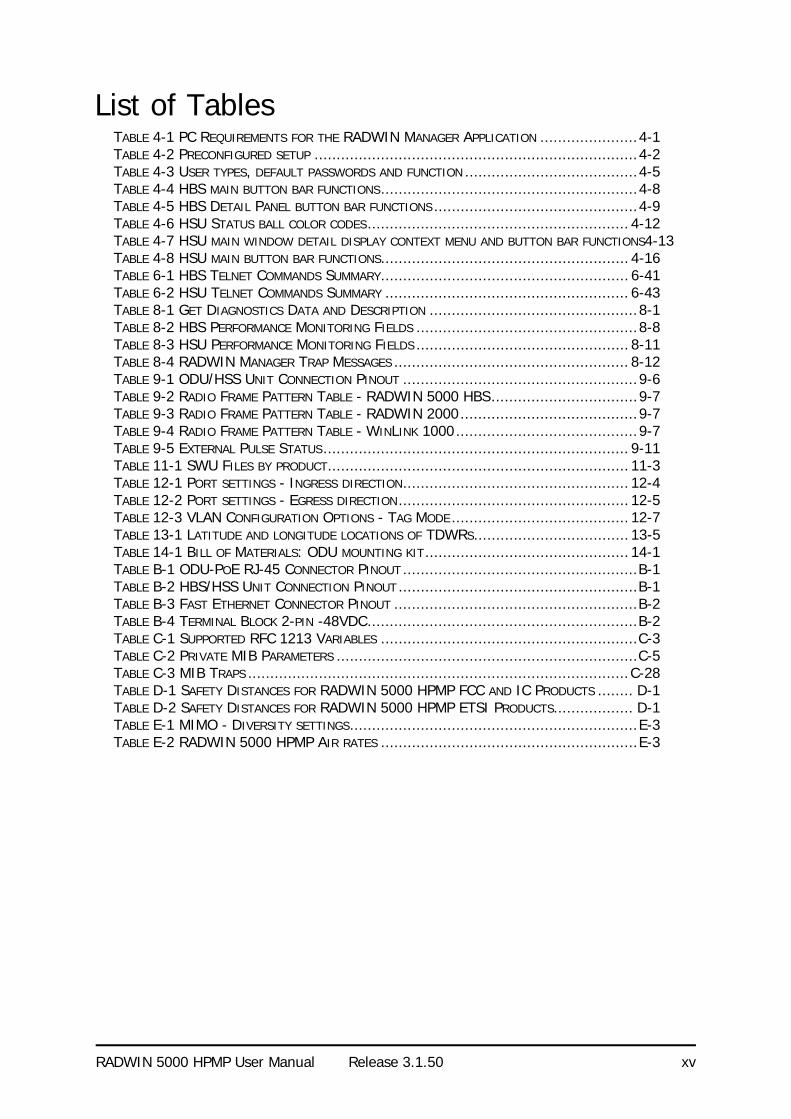
List of TablesTABLE 4-1 PC REQUIREMENTS FOR THE RADWIN MANAGER APPLICATION ......................4-1TABLE 4-2 PRECONFIGURED SETUP .........................................................................4-2TABLE 4-3 USER TYPES, DEFAULT PASSWORDS AND FUNCTION .......................................4-5TABLE 4-4 HBS MAIN BUTTON BAR FUNCTIONS..........................................................4-8TABLE 4-5 HBS DETAIL PANEL BUTTON BAR FUNCTIONS ..............................................4-9TABLE 4-6 HSU STATUS BALL COLOR CODES........................................................... 4-12TABLE 4-7 HSU MAIN WINDOW DETAIL DISPLAY CONTEXT MENU AND BUTTON BAR FUNCTIONS4-13TABLE 4-8 HSU MAIN BUTTON BAR FUNCTIONS........................................................ 4-16TABLE 6-1 HBS TELNET COMMANDS SUMMARY........................................................ 6-41TABLE 6-2 HSU TELNET COMMANDS SUMMARY ....................................................... 6-43TABLE 8-1 GET DIAGNOSTICS DATA AND DESCRIPTION ...............................................8-1TABLE 8-2 HBS PERFORMANCE MONITORING FIELDS ..................................................8-8TABLE 8-3 HSU PERFORMANCE MONITORING FIELDS ................................................ 8-11TABLE 8-4 RADWIN MANAGER TRAP MESSAGES ..................................................... 8-12TABLE 9-1 ODU/HSS UNIT CONNECTION PINOUT .....................................................9-6TABLE 9-2 RADIO FRAME PATTERN TABLE - RADWIN 5000 HBS.................................9-7TABLE 9-3 RADIO FRAME PATTERN TABLE - RADWIN 2000........................................9-7TABLE 9-4 RADIO FRAME PATTERN TABLE - WINLINK 1000.........................................9-7TABLE 9-5 EXTERNAL PULSE STATUS..................................................................... 9-11TABLE 11-1 SWU FILES BY PRODUCT.................................................................... 11-3TABLE 12-1 PORT SETTINGS - INGRESS DIRECTION................................................... 12-4TABLE 12-2 PORT SETTINGS - EGRESS DIRECTION.................................................... 12-5TABLE 12-3 VLAN CONFIGURATION OPTIONS - TAG MODE ........................................ 12-7TABLE 13-1 LATITUDE AND LONGITUDE LOCATIONS OF TDWRS................................... 13-5TABLE 14-1 BILL OF MATERIALS: ODU MOUNTING KIT.............................................. 14-1TABLE B-1 ODU-POE RJ-45 CONNECTOR PINOUT .....................................................B-1TABLE B-2 HBS/HSS UNIT CONNECTION PINOUT ......................................................B-1TABLE B-3 FAST ETHERNET CONNECTOR PINOUT .......................................................B-2TABLE B-4 TERMINAL BLOCK 2-PIN -48VDC.............................................................B-2TABLE C-1 SUPPORTED RFC 1213 VARIABLES ..........................................................C-3TABLE C-2 PRIVATE MIB PARAMETERS ....................................................................C-5TABLE C-3 MIB TRAPS ......................................................................................C-28TABLE D-1 SAFETY DISTANCES FOR RADWIN 5000 HPMP FCC AND IC PRODUCTS ........ D-1TABLE D-2 SAFETY DISTANCES FOR RADWIN 5000 HPMP ETSI PRODUCTS.................. D-1TABLE E-1 MIMO - DIVERSITY SETTINGS.................................................................E-3TABLE E-2 RADWIN 5000 HPMP AIR RATES ..........................................................E-3

RADWIN 5000 HPMP
Point to Multipoint Broadband Wireless
USER MANUAL
RELEASE 3.1.50
Part 1: Basic Installation
UM 5000-3150/06.11

RADWIN 5000 HPMP User Manual Release 3.1.50 1-1
Chapter 1
Introduction
Welcome to RADWIN 5000 HPMP!
RADWIN 5000 HPMP delivers up to 200Mbps and is the ideal choice for last mile enterprise connectivity and high-end applications that demand assured performance with guaranteed bandwidth per subscriber.
RADWIN 5000 HPMP sector base station delivers up to 200Mbps, providing the highest end user capacity in the market to best support data and high resolution video applications, today and tomorrow. By delivering high capacity over a single radio unit, RADWIN solution saves valuable tower space, eases maintenance efforts and reduces the total cost of ownership per megabit. Offering a variety of powerful SUs, RADWIN 5000 HPMP enables service capacity of up to 50Mbps for enterprise customers.
RADWIN 5000 HPMP Highlights
• High capacity Sector Base Station• 200 Mbps aggregate throughput• Ethernet connectivity
• High capacity end user equipment - 10, 20, 50Mbps• Up to 16 Subscriber Units per sector• Guaranteed SLA and capacity per Subscriber Unit
• Small and constant latency - 4 to 10msec typical under full sector load• Wide range of frequency bands - 4.9 to 6GHz
What’s New in Release 3.1.50
• VLAN support• VLAN support for Management• Active Alarms
• HSU replacement• Antenna Mode – Single/MIMO/Diversity• 10MHz channel BW support
• Telnet Interface support
Some Terminology Chapter 1
RADWIN 5000 HPMP User Manual Release 3.1.50 1-2
• False radar mitigation• Sector wise: License key, Band Activation• Sector wise: Change band
• Manager On-Line Help
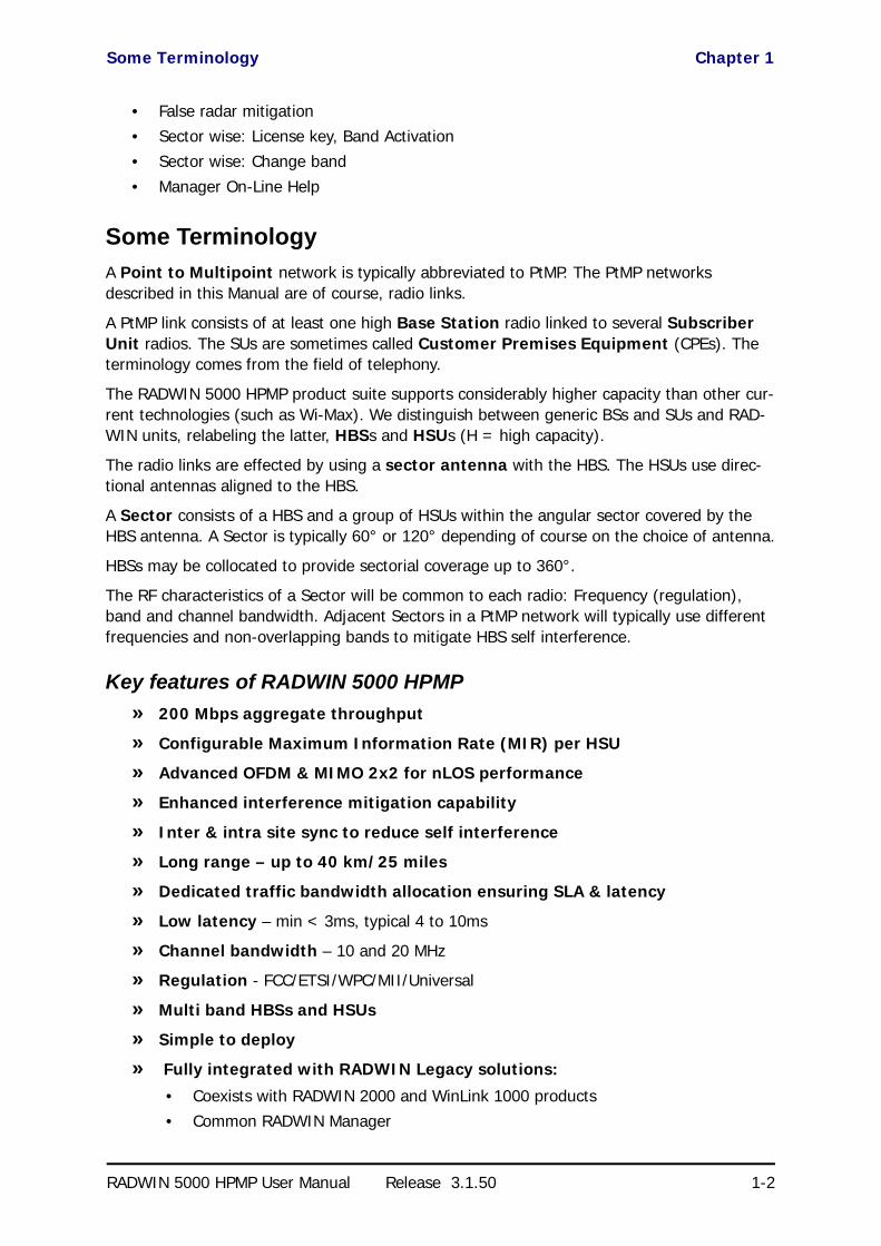
Some Terminology
A Point to Multipoint network is typically abbreviated to PtMP. The PtMP networks described in this Manual are of course, radio links.
A PtMP link consists of at least one high Base Station radio linked to several Subscriber Unit radios. The SUs are sometimes called Customer Premises Equipment (CPEs). The terminology comes from the field of telephony.
The RADWIN 5000 HPMP product suite supports considerably higher capacity than other cur-rent technologies (such as Wi-Max). We distinguish between generic BSs and SUs and RAD-WIN units, relabeling the latter, HBSs and HSUs (H = high capacity).
The radio links are effected by using a sector antenna with the HBS. The HSUs use direc-tional antennas aligned to the HBS.
A Sector consists of a HBS and a group of HSUs within the angular sector covered by the HBS antenna. A Sector is typically 60° or 120° depending of course on the choice of antenna.
HBSs may be collocated to provide sectorial coverage up to 360°.
The RF characteristics of a Sector will be common to each radio: Frequency (regulation), band and channel bandwidth. Adjacent Sectors in a PtMP network will typically use different frequencies and non-overlapping bands to mitigate HBS self interference.
Key features of RADWIN 5000 HPMP
» 200 Mbps aggregate throughput
» Configurable Maximum Information Rate (MIR) per HSU
» Advanced OFDM & MIMO 2x2 for nLOS performance
» Enhanced interference mitigation capability
» Inter & intra site sync to reduce self interference
» Long range – up to 40 km/25 miles
» Dedicated traffic bandwidth allocation ensuring SLA & latency
» Low latency – min < 3ms, typical 4 to 10ms
» Channel bandwidth – 10 and 20 MHz
» Regulation - FCC/ETSI/WPC/MII/Universal
» Multi band HBSs and HSUs
» Simple to deploy
» Fully integrated with RADWIN Legacy solutions:
• Coexists with RADWIN 2000 and WinLink 1000 products• Common RADWIN Manager

RADWIN 5000 HPMP Components Chapter 1
RADWIN 5000 HPMP User Manual Release 3.1.50 1-3
• Common RNMS
RADWIN 5000 HPMP ComponentsRADWIN 5000 HBS High Capacity Base Station
The HBS consists of RADWIN 5000 HBS HBS ODU, a sector dual-pole antenna and a PoE device, which provides a LAN interface to user equipment.
A single HBS supports up to 16 HSUs.
Figure 1-1: Single Sector Base Station
RADWIN 55xx HSU High Capacity Subscriber Units
An HSU consists of a RADWIN 55xx HSU ODU. It may be a small form factor (SFF) model with a built in antenna, or a regular integrated or connectorized unit. The latter should use a dual pole antenna for best performance.
Figure 1-2: Small form factor antenna in connectorized ODU
Figure 1-3: High gain integrated antenna
Figure 1-4: Connectorized ODU

The RADWIN Manager Chapter 1
RADWIN 5000 HPMP User Manual Release 3.1.50 1-4
The RADWIN Manager
The RADWIN Manager is an SNMP-based management application which manages a com-plete sector over a single IP address. It can also manage HSUs separately.
The intuitive, easy-to-use RADWIN Manager has a graphical Microsoft Windows interface.
Conventions Used in this Manual
Notifications
Notifications consist of Notes, Cautions and Warnings.
Typographical conventionsGeneral
Where a term is defined or introduced for the first time, it is shown in Boldface. You will have noticed this usage in the Terminology section above.
Software
The RADWIN Manager is a Microsoft Windows application following the user interface con-ventions of familiar Microsoft Windows programs.
Note
The purpose of a Note is to
• Draw your attention to something that may not be obvious or coun-ter-intuitive
• Emphasize a special feature or peculiarity of the RADWIN 5000 HPMP• Offer an external reference for additional information• Add a caveat that would not qualify as a full Caution or Warning (see
below)• Provide additional background to what follows• Offer a recommendation• Highlight an indication of something to watch out for• Advise you if an action has “side effects” i.e. it may disturb something
else that would be best left undisturbed• Remind you of something that should be kept in mind
Caution
A Caution is a notification of risk of damage to equipment or of service degradation
Warning
A Warning is a notification of risk of danger to persons operating near the equipment
Viewing and Printing Chapter 1
RADWIN 5000 HPMP User Manual Release 3.1.50 1-5
Viewing and Printing
This manual is optimized for viewing online as a PDF file. To this end it uses an 11 point Tahoma typeface for main text. Tables for most part, use 7 or 8 point fonts. Here are a few pointers for hard-copy printing:
• The text and table typefaces used are large enough to print the manual at two pages per sheet
• For good legibility, use a commercial grade laser printer. A color printer is of course best, however a monochrome printer set to use gray-scale gives acceptable results
• Better quality ink jet printers also give good output
RADWIN 5000 HPMP User Manual Release 3.1.50 2-1
Chapter 2
Site PreparationPlanning the Sector Site
Overview
Sector site planning consists of a set of surveys, which must be carried out before any equip-ment is deployed. If for some reason, the outcome of any of these surveys is negative, HBS or HSU re-location will need to be considered.
A Site Survey consists of three stages:
1. Preliminary survey - The proposed sector is analyzed in the office using a topographic map. You should use additional tools such as the Link Budget Calculator or the Radio Plan-ner.
2. Physical survey - The locations of the indoor and outdoor equipment are determined on-site.
3. Radio Frequency (RF) survey - It is recommended that the installation area be scanned with a spectrum analyzer, to identify RF interference so as to determine a clear channel for radio installation (on-site).
The Site Survey
Introduction
RADWIN wireless links must be planned before installation. The designated installation sites must be appraised to determine that the wireless system is able to operate efficiently and provide connectivity without signal degradation.
RADWIN 5000 HPMP offers a wide operating frequency range. A free frequency channel must be determined within the operating range, for optimum performance.
Recommended EquipmentStage 1: Preliminary Survey
• Topological map of the area• Urban map of the area• Compass

Stage 1: Preliminary Survey Chapter 2
RADWIN 5000 HPMP User Manual Release 3.1.50 2-2
• Link Budget Calculator and/or Radio PlannerStage 2: Physical Survey
• 100 meter tape measure• Ohmmeter, to check ground connection• Binoculars
• Map• Digital camera• Paper, pencil, and a clipboard
• GPS device (optional)• Compass (optional)
Stage 3: RF Survey• Spectrum Analyzer with Max Hold function and screen capture facility that can store
multiple images, for documentation purposes• RF accessories (connectors and cables)• Communication devices (for example, cellular phones, or a set of walkie-talkies)
Stage 1: Preliminary Survey
A preliminary survey is necessary before visiting potential installation sites. As much detail as possible should be obtained about the designated ODU installation sites and the area between them.
To perform a preliminary survey:
1. Mark the designated installation sites on a topographic map of the area.
2. Measure the distance between the sites; check that it is within the specified range of the equipment.
3. On the urban map, check for developed areas situated between the installation sites. Pay attention to these areas when performing the physical site survey; there may be tall buildings, RF towers, or transmitters, which could cause interference to a sector.
4. Check the area between the two sites for obstructions such as:
• High ground - hills or mountains• Lakes or large bodies of water. Water has a reflection effect on RF signals like a
building. This type of reflection causes the received amplitude to be reduced. As a rule of thumb, the presence of a large body of water between sector sites may double the required antenna height.
5. Determine and record the compass bearings between HBS and HSU ODUs, relative to north.
6. If there are obstructions between the two sites, calculate the Fresnel Zone (see Chapter 16 for details).
7. If the sites chosen do not meet requirements, consider alternative sites.
8. Use the Link Budget Calculator (on the CD supplied with the equipment or using the RADWIN Manager) to determine the expected performance.

Stage 2: Physical Survey Chapter 2
RADWIN 5000 HPMP User Manual Release 3.1.50 2-3
Stage 2: Physical Survey
The physical site survey reviews the environment of the proposed installation location, to ensure that the sector sites are suitable for the wireless network. The results of the physical site survey should be recorded.
To perform a physical survey:
1. From the compass readings taken in the preliminary survey, find the azimuth (hori-zontal position) that each HSU ODU should face towards the HBS ODU.
2. Using binoculars, locate any obstructions such as tall trees, high buildings, hills or mountains. Look for other RF towers between the two sites. Mark the locations of the obstructions on the map.
3. Determine the location for the ODU (having regard for existing rooftop installations and tower space). It should be above any obstructions, considering the Fresnel zone (see Chapter 16).
4. If you need to install an ODU on a tower, make sure that the tower is far enough from overhead electric power lines.
5. Determine a location for the indoor equipment; it should be as close as possible to the ODU. At an existing site, there is probably an equipment room with cable-routing channels.
6. Measure and record the path length of the cable from each ODU position to the indoor equipment room.
7. Determine the ground and lightning connection points of the installation. The ODU and PoE must both be grounded.
8. Using the Ohmmeter, measure and record the resistance of the required installation to the grounding point. The resistance must be less than 1O ohm.
9. Review the results of the physical site survey. Decide if the site is suitable for the wireless network installation.
• If the site is suitable, continue with stage 3, the RF survey• If the site is not suitable, survey another site
Additional Outdoor Site Requirements
The ambient outdoor operating temperature should be -35 to 60C (-31 to 140F).
Note
It is advisable to go on a clear day, so you can more easily see any obstructions between the two sites.
Note
Outdoor CAT-5e; Maximum cable length: 100m for 10/100BaseT and 75m for 1000BaseT (GbE PoEs)
Additional Indoor Site Requirements Chapter 2
RADWIN 5000 HPMP User Manual Release 3.1.50 2-4
Additional Indoor Site Requirements
The ambient operating temperature should be 0 to 50°C (32 to 122 °F) at a humidity of up to 90%, non condensing
Stage 3: RF Survey
The RF survey examines the wireless environment of the installation site, to determine whether there are available channels within the radio operating frequency band. An RF survey is performed using a spectrum analyzer.
It is advisable to familiarize yourself with the spectrum analyzer before going out on site, spe-cifically the Max Hold and Marker functions.
You should perform the RF survey at each of the proposed sector sites.
The survey should be carried out during a busy time of day, to best judge the worst-case radio interference. Allow 2-4 hours duration for a good RF survey.
RF Planning for Dense Installations and Collocated Sites
Interference may arise from
• Self-interference from collocated RADWIN radios• Other collocated radio devices installed on the same site.
To avoid or minimize interference, follow these recommendations:
• For collocated RADWIN units, use an HSS unit to synchronize between them. Select a different operating channels for each collocated RADWIN unit.
• If one or more collocated units are not RADWIN units, ensure that there is a physical separation of at least three meters between a RADWIN unit and any other collocated radio on the site.
• Use the largest possible frequency gap between these units
• Choose the best frequency channel (as clear as possible from interference). You may be able to change the band used for the sector - depending on HBS model and regu-lations.
• Decreasing the Tx Power of a sector will reduce collocation interference
Note
Use the Link Budget Calculator to determine the minimum Tx Power required to maintain sector stability.

RADWIN 5000 HPMP User Manual Release 3.1.50 3-1
Chapter 3
Hardware InstallationThis chapter sets out the requirements and procedures for the hardware installation and alignment of a RADWIN 5000 HPMP sector in accordance with the prior planning as set out in Chapter 2. It is intended to guide qualified field technicians.
Safety Practices
Preventing overexposure to RF energy
To protect against overexposure to RF energy, install the ODUs so as to provide and maintain minimal separation distances from all persons.
When the system is operational, avoid standing directly in front of the antenna. Strong RF fields are present when the transmitter is on. The ODU must not be deployed in a location where it is possible for people to stand or walk inadvertently in front of the antenna.
Grounding
All RADWIN products should be grounded during operation. In addition:
• The ODU should be earthed by a wire with diameter of at least 12AWG.RADWIN 5000 HPMP ODUs must be properly grounded to protect against lightning. It is the user's responsibility to install the equipment in accordance with Section 810 of the National Electric Code, ANSI/NFPA No.70-1984 or Section 54 of the Canadian Electrical Code. These codes describe correct installation procedures for grounding
Warning
Outdoor units and antennas should be installed ONLY by experienced installation professionals who are familiar with local building and safety codes and, wherever applicable, are licensed by the appropriate government regulatory authorities. Failure to do so may expose the end user or the service provider to legal and financial liabilities. RADWIN and its resellers or distributors are not liable for injury, damage or violation of regulations associated with the installation of outdoor units or antennas.
Note
The material in this chapter is generic to all RADWIN radio products unless stated otherwise.

Protection against Lightning Chapter 3
RADWIN 5000 HPMP User Manual Release 3.1.50 3-2
outdoor units, masts, lead-in wiring and discharge units. It also lays down the size of grounding conductors and connection requirements for grounding electrodes.RADWIN 5000 HPMP ODUs must be grounded to a Protective Earth as described in Chapter 15 and in accordance with the Local Electrical Regulations.
Further, you should -
• Always make the ground connection first and disconnect it last
• Never connect telecommunication cables to ungrounded equipment• Ensure that all other cables are disconnected before disconnecting the ground
More detailed guidelines are supplied in Chapter 15.
Protection against Lightning
The use of lightning protection is dependent on regulatory and end user requirements. All of RADWIN outdoor units are designed with surge limiting circuits to minimize the risk of dam-age due to lightning strikes. RADWIN recommends the use of additional surge arrestor devices to protect the equipment from nearby lightning strikes.
See Chapter 15 for detailed installation instructions of lightning protection devices.
General• It is recommended that installation of the outdoor unit be contracted to a professional
installer.
• Before working on equipment connected to power lines or telecommunication lines, you should remove jewelry or any other metallic object that may come into contact with energized parts.
• Use extreme care when installing antennas near power lines.• Use extreme care when working at heights.• When using an AC power source for RADWIN 5000 HPMP PoEs always use the AC
power adapter supplied by RADWIN.• Use the right tools. In addition to standard tools required for any kind of ODU or
antenna installation, RADWIN 5000 HPMP ODUs require additional specific tools detailed on page 3-7 below.
Package Contents
The RADWIN 5000 HPMP packages include the following items:
HBS and HSU ODU Package Contents
The ODU package contains:
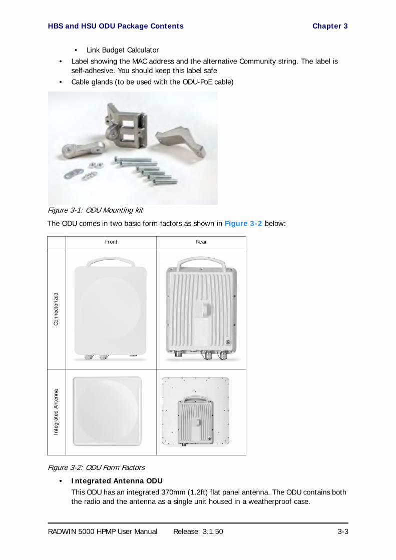
• One HBS or HSU ODU - see Figure 3-2 below for front and rear view• An ODU mounting kit - see Figure 3-1 below• A CD containing -
• the RADWIN Manager• Quick Start Guide
• User Manual - the document you are reading
HBS and HSU ODU Package Contents Chapter 3
RADWIN 5000 HPMP User Manual Release 3.1.50 3-3
• Link Budget Calculator• Label showing the MAC address and the alternative Community string. The label is
self-adhesive. You should keep this label safe
• Cable glands (to be used with the ODU-PoE cable)
Figure 3-1: ODU Mounting kit
The ODU comes in two basic form factors as shown in Figure 3-2 below:
Figure 3-2: ODU Form Factors
• Integrated Antenna ODUThis ODU has an integrated 370mm (1.2ft) flat panel antenna. The ODU contains both the radio and the antenna as a single unit housed in a weatherproof case.
Front Rear
Conn
ecto
rized
Inte
grat
ed A
nten
na

External Antenna Package Contents Chapter 3
RADWIN 5000 HPMP User Manual Release 3.1.50 3-4
• Connectorized ODUThis ODU has 2xN-type connectors for connecting an external antenna
• HSU only - SFF (Connectorized) ODUThe SFF ODU is slightly “fatter” and heavier than a regular connectorized ODU since it requires extra space for the built-in antenna.
External Antenna Package Contents
The HBS requires a dual pole sector antenna. HSUs may use any suitable dual pole directional antenna.
External antennas are available for the RADWIN 5000 HPMP radios, varying in operating fre-quencies, form factor, size and gain.
Figure 3-3: External Antennas for use with RADWIN 5000 HPMP
See the RADWIN products catalog for RADWIN offering of external antennas. External anten-nas are also available from third party antenna vendors.
Antenna kits contain -
• An antenna• Two RF cable 1m (3’) long
• Mounting kit
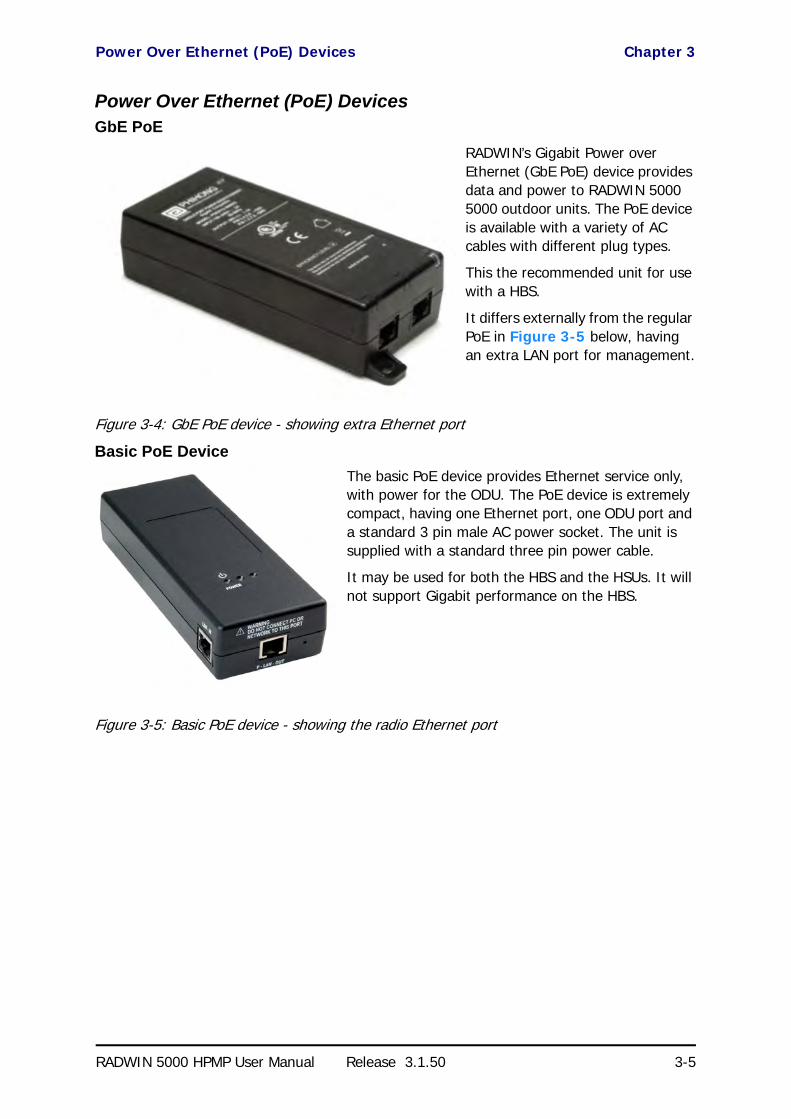
Power Over Ethernet (PoE) Devices Chapter 3
RADWIN 5000 HPMP User Manual Release 3.1.50 3-5
Power Over Ethernet (PoE) DevicesGbE PoE
RADWIN’s Gigabit Power over Ethernet (GbE PoE) device provides data and power to RADWIN 5000 5000 outdoor units. The PoE device is available with a variety of AC cables with different plug types.
This the recommended unit for use with a HBS.
It differs externally from the regular PoE in Figure 3-5 below, having an extra LAN port for management.
Figure 3-4: GbE PoE device - showing extra Ethernet port
Basic PoE Device
The basic PoE device provides Ethernet service only, with power for the ODU. The PoE device is extremely compact, having one Ethernet port, one ODU port and a standard 3 pin male AC power socket. The unit is supplied with a standard three pin power cable.
It may be used for both the HBS and the HSUs. It will not support Gigabit performance on the HBS.
Figure 3-5: Basic PoE device - showing the radio Ethernet port

Hub Site Synchronization (HSS) Unit Chapter 3
RADWIN 5000 HPMP User Manual Release 3.1.50 3-6
Outdoor (Ruggedized) DC PoE Device
This unit may be used or both the HBS and the HSUs. It will not support Gigabit performance on the HBS.
Figure 3-6: Ruggedized DC-PoE Device: Input is -20 to -60 VDC (single input)
Hub Site Synchronization (HSS) Unit
The HSS unit synchronizes collocated ODUs to prevent self interference. It is particularly use-ful at a multi-sector base station employing several HBSs.
A single HSS unit supports up to ten collocated ODUs. In addition to each unit being con-nected to its PoE device, the collocated unit has an additional cable that is connected to the HSS Unit. The HSS Unit is a compact, weatherproof (IP67) connector box that is installed on the same mast as the ODUs. All collocated units connect to this box using CAT-5e cable. Cables in prepared lengths are available for purchase.
The HSS unit is supplied with ten protective covers; any port not in use must be closed with a protective cover.
Figure 3-7: HSS Interconnection Unit
See Chapter 9 for further details about the use of HSS.
GSU
The GPS-based synchronization unit (GSU) is designed to handle inter-site interferences under large-scale deployment scenarios.
The GSU is an outdoor unit consisting of a standard WinLink 1000 enclosure, a GPS antenna and a PoE device.

Additional Tools and Materials Required Chapter 3
RADWIN 5000 HPMP User Manual Release 3.1.50 3-7
The GSU is connected to the HSS Unit using a standard HSS cable. It synchronizes the trans-mission timing of multiple Hub-Sites to the same clock source thus eliminating self interfer-ence (see Chapter 10).
Figure 3-8: General GSU configuration
See Chapter 10 for further details about the use of GSU.
Additional Tools and Materials Required
The following is a list of the equipment and materials required to install RADWIN 5000 HPMP hardware.
Tools and Materials• Crimping tool for RJ-45 (if the ODU-PoE cable is without connectors)• Spanner/wrench 13 mm (½”) • Drill (for wall mounting only)
• Cable ties• Sealing material
Cables and connectors• ODU grounding cable 12AWG

Hardware Installation Sequence Chapter 3
RADWIN 5000 HPMP User Manual Release 3.1.50 3-8
• ODU-PoE cable (outdoor class, CAT-5e, 4 twisted pairs, 24AWG), up to 100 m. for 100BaseT connection. For a 1000BaseT connection (HBS only) use an ODU-PoE cable no longer than 75m.
• A crossed Ethernet LAN cable is required if you set up ODUs using the “Local Connec-tion” method.
Hardware Installation Sequence
The following steps are required to install a RADWIN 5000 HPMP system:
1. Mounting the ODUs, page 3-9.
2. Mounting the external antennas (if used), page 3-10.
3. Mounting the Lightning Protection devices (if used), page 3-10.
4. Outdoor connections, page 3-10.
5. Connecting the PoEs, page 3-11.
6. Other Indoor connections, page 3-11.
7. Aligning the HSUs to the HBS, page 3-11.
See Figure 3-9 below, which illustrates a typical installation of a RADWIN 55xx HSU with an external antenna.
Note
For 1000BaseT, you should use RADWIN supplied ODU-PoE cables, which guarantee 1Gb performance. RADWIN cannot guarantee 1Gb performance if you use third party cables.
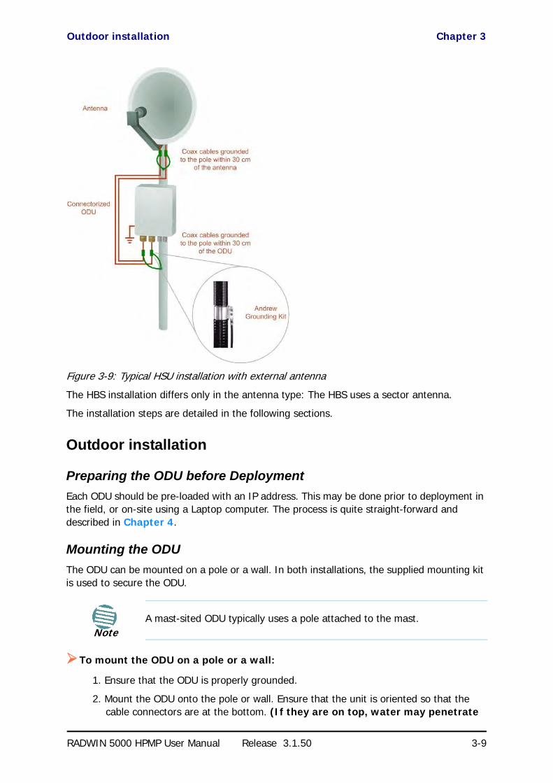
Outdoor installation Chapter 3
RADWIN 5000 HPMP User Manual Release 3.1.50 3-9
Figure 3-9: Typical HSU installation with external antenna
The HBS installation differs only in the antenna type: The HBS uses a sector antenna.
The installation steps are detailed in the following sections.
Outdoor installation
Preparing the ODU before Deployment
Each ODU should be pre-loaded with an IP address. This may be done prior to deployment in the field, or on-site using a Laptop computer. The process is quite straight-forward and described in Chapter 4.
Mounting the ODU
The ODU can be mounted on a pole or a wall. In both installations, the supplied mounting kit is used to secure the ODU.
To mount the ODU on a pole or a wall:
1. Ensure that the ODU is properly grounded.
2. Mount the ODU onto the pole or wall. Ensure that the unit is oriented so that the cable connectors are at the bottom. (If they are on top, water may penetrate
NoteA mast-sited ODU typically uses a pole attached to the mast.

Mounting external antennas Chapter 3
RADWIN 5000 HPMP User Manual Release 3.1.50 3-10
into the unit causing damage.) It is possible to mount an ODU horizontally. See Chapter 14 for details.
3. Refer also to Chapter 14 for detailed ODU mounting kit contents and schematics.
Mounting external antennas
If you are using ODU with an integrated antenna, skip to Mounting the Lightning Protec-tion Devices below.
The supplied mounting kit is used to mount the antenna onto a pole. The antennas must be aligned for maximum throughput.
To mount an external antenna:
1. To mount an external antenna, ensure that the antenna is properly grounded and then mount the antenna onto the pole. Refer to Chapter 14 for detailed antenna mounting instructions.
2. Follow the mounting instructions supplied with the antenna.
Mounting the Lightning Protection Devices
The use of lightning protection is dependent on regulatory and end user requirements. The RADWIN 5000 HPMP ODU is designed with surge limiting circuits to minimize the risk of dam-age due to lightning strikes. RADWIN recommends the use of additional surge arrestor devices to protect the equipment from nearby lightning strikes.
Refer to Chapter 15 for detailed installation instructions of lightning protection devices.
Outdoor Connections
To complete the outdoor connections:
1. Connect the ground cable to the ODU chassis as marked on the ODU.
Warning
Prior to connecting cables to the ODU, the protective earth terminal (screw) of the ODU must be connected to an external protective ground conductor or to a grounded pole.
• Only a qualified person using the proper safety equipment should climb the antenna mast
• Only qualified professional personnel should install or dismantle ODUs and masts
Note
• Do not tighten the ODU to its mounting brackets until the alignment process of the antenna is complete.
• Ensure that there are no direct obstructions in front of the ODU or interference from man-made obstacles.
WarningNever stand in front of a live antenna!

Installing a Sector using PoE Devices Chapter 3
RADWIN 5000 HPMP User Manual Release 3.1.50 3-11
2. Connect the lightning protection device to the ODU (see Chapter 15).
3. Attach the ODU-PoE cable to the ODU RJ-45 connector (see Appendix B for the connector pinout)
4. Screw in the cable glands to ensure hermetic sealing of the ODU.
5. Secure the cables to the pole, mast or brackets using UV-rated cable ties.
Installing a Sector using PoE Devices
A typical PoE device is a very simple unit having a power input connector and two Ethernet ports. It is AC powered, and has a power LED.
To prepare a sector using PoE devices:
1. To connect the ODU to the PoE device, route the cable from the ODU to the PoE device, secure the cable along its path and connect the cable to the LAN-OUT RJ-45 connector on the PoE device.
2. Connect it to AC power.
3. Repeat steps 1 to 2 for all ODUs in the sector.
Connecting User Equipment
To connect user equipment to a PoE device:
• Connect a user switch, router or any other compatible device to the PoE device RJ-45 port designated LAN-IN. Refer to Appendix B for connector pinouts.
Aligning HSUs to a HBS
You perform HSU antenna alignment to a HBS using the HSU ODU’s audible tone.
To align a HSU to its HBS:
1. Ensure that the sector antenna of the HBS is aligned precisely to the sector it is intended to cover. Use a compass and topographical maps to do this.
2. For both the HBS and HSUs: Using a coax cable with N-Type connectors, connect the vertical polarization connector of the antenna to the ANT 1 connector of the ODU. Then, using a second coax cable with N-Type connectors, connect the horizontal polarization connector of the antenna to the ANT 2 connector of the ODU.
3. Ensure that power is connected to the site PoEs across the sector.
4. Provided that an HSU detects the signal from the HBS, the ODU starts beeping 20 seconds after power up, and continues beeping until the HSU is aligned to the HBS, and the alignment is complete.
Note
There is no particular reason to use ANT 1 and ANT 2 in that order: They just have to be the same for each ODU in the sector. Further, adopting a convention like “ANT 1 is always vertical” avoids mistakes across a large sector.

Aligning HSUs to a HBS Chapter 3
RADWIN 5000 HPMP User Manual Release 3.1.50 3-12
The details are described in the next two steps. “Antenna” refers both to an external antenna and an integrated antenna. The two steps should be carried out for each HSU in the sector.
5. Make a horizontal sweep of 180 degrees with the HSU antenna so that the strongest signal from the HBS can be detected.
6. Slowly turn the HSU antenna back towards the position of the HBS, listening to the tone until the best signal is reached. See the following figure for audible signal varia-tions.
Figure 3-10: Beep Sequence for antenna alignment
7. Secure the HSU antenna to the pole/wall.
WarningNever stand in front of a live antenna!
Note
• Three beeps and a pause is 'best signal so far'• Two beeps and a pause is 'signal quality increased'• One beep and pause is 'no change in signal'• Long beep and short pause is 'signal quality decreased'• One beep and a long pause is 'no air link'• Any other signal does not relate to antenna alignment

RADWIN 5000 HPMP
Point to Multipoint Broadband Wireless
USER MANUAL
RELEASE 3.1.50
Part 2: Sector Installation
UM 5000-3150/06.11

RADWIN 5000 HPMP User Manual Release 3.1.50 4-1
Chapter 4
Getting Started with theRADWIN Manager
What we will do here
This chapter is a quick “hands-on” tour of a running sector. We show you how to install the RADWIN Manager software on your managing PC, connect it to an operating base station and then log on. We then explain the use of the various objects on the RADWIN Manager main window.
The background acquired here will enable you to understand the direction and purpose of the detailed procedures (described in later chapters) required to build a RADWIN 5000 HPMP sec-tor from the ground up.
Installing the RADWIN Manager Application
Minimum System Requirements
The RADWIN Manager application is distributed on a CD. Operating system specific PC resources required by the application are set out in Table 4-1 below:
Requirements common to all systems are:
• Hard disk: 1 GB free space• Network: 10/100BaseT NIC• Graphics: 1024x768 screen resolution with 16 bit color
Table 4-1: PC Requirements for the RADWIN Manager Application
Windows Version
XP ProVista/7t
32 bit 64 bit
Memory 512 Mb 1 Gb 2 Gb
Processor P IV P IV Dual Core

Installing the Software Chapter 4
RADWIN 5000 HPMP User Manual Release 3.1.50 4-2
• Any modern Web browser to view additional material or get help from the RADWIN Web site.
Installing the Software
Any PC running the RADWIN Manager application can be used to configure a RADWIN 5000 HPMP sector.
To install the RADWIN Manager application:
1. Insert the CD into the CD/DVD drive of your computer.
2. Choose Install RADWIN Manager and follow the on-screen instructions of the instal-lation wizard to complete the setup of the RADWIN Manager application.
If the installation program fails to start, browse to your CD/DVD drive, chose the setup.exe program and run it.
Getting Started with the RADWIN Manager
We will look at a preconfigured setup as follows:
Table 4-2: Preconfigured setup
Unit Location Attribute Value Remark
HBS HBS_10.200
IP Address 192.168.10.200
All communicating HSUs and HBS in the same subnet
Net Mask 255.255.255.0
Default Gateway 0.0.0.0
Sector ID EBG_20560334 Inherited by all communicating HSUs
Contact Bach Optional
Name Bach’s Office Location of Contact - optional
Band 5.730 - 5.845 GHz FCC/IC Inherited by all communicating HSUs
Channel Bandwidth 20MHz Inherited by all communicating HSUs
HSU
HSU_10.101
IP Address 192.168.10.101
All communicating HSUs and HBS in the same subnet
Net Mask 255.255.255.0
Default Gateway 0.0.0.0
Contact Haydn
Name Haydn’s Office
HSU_10.102
IP Address 10.103.15.8
All communicating HSUs and HBS in the same subnet
Net Mask 255.255.255.0
Default Gateway 0.0.0.0
Contact Mozart
Name Mozart’s Office

Getting Started with the RADWIN Manager Chapter 4
RADWIN 5000 HPMP User Manual Release 3.1.50 4-3
To start the RADWIN Manager:
1. Connect the managing computer to the HBS PoE LAN port.
2. Check that you have connectivity to the HBS ODU. You can do this by opening up a command line session (Start|Run and then type, cmd). At the command prompt, type
ping 192.168.10.200
You should see something like this:
Figure 4-1: Pinging the base station.
Any other response from ping means that the HBS ODU is not responding. Check your Ethernet connection and that both the PoE and ODU are switched on and then try again. If you do not succeed, seek assistance from RADWIN Customer Support.
Pinging the HSUs should yield similar responses.
3. Dismiss the command line session.
4. Open the RADWIN Manager from the desktop icon, or click Start|Programs|RAD-WIN Manager|RADWIN Manager.
The Log-on dialog box appears.
Tip
Choose your unit names carefully. For example, for three collocated HBSs each with 16 HSUs covering 360°, matters get out of hand very quickly if units are poorly named. They can always be identified by their IP addresses, but that is a poor substitute for effective naming. A URL-like naming pattern based on HBS_n.HSU_y is clear and familiar to all Internet users.
In a scenario like our example (one HBS, two HSUs) that would have been be unduly complicated and detracting.

The RADWIN Manager log-on Concept Chapter 4
RADWIN 5000 HPMP User Manual Release 3.1.50 4-4
Figure 4-2: Log-on window
The RADWIN Manager log-on Concept
The RADWIN Manager provides three levels of access in one of two entry modes. To see them, click Options at any time in the Log on window (Figure 4-2 above). You are offered an extended log-on window:
Figure 4-3: Extended log-on window
At the User Type field, click the list button:

The RADWIN Manager log-on Concept Chapter 4
RADWIN 5000 HPMP User Manual Release 3.1.50 4-5
Figure 4-4: Log on window exposing the user types.
There are three user types:
• An Observer has read-only access to the sector. An Observer can monitor the sector, generate reports, but may not change any sector parameters.
• An Operator can install and configure the sector.• An Installer can, in addition to functioning as an Operator, also change the operating
frequency band (or regulation). The latter function has legal ramifications, requiring familiarity with local regulations.
If you are connecting through the RNMS server check the RMNS connect button and enter your server IP address.
The following table summarizes these options:
The Network Manager should change the default passwords as soon as possible.
Continuing the log-on procedure:
5. If your User Type is not Operator, then choose it now.
6. Enter the password.
Table 4-3: User types, default passwords and function
User Type Default Password Function Community Community
String
Observer admin Monitoring Read-Only public
Operator admin Installation, configuration
Read-Write netman
Installer wireless Operator plus set band
Read-Write netman
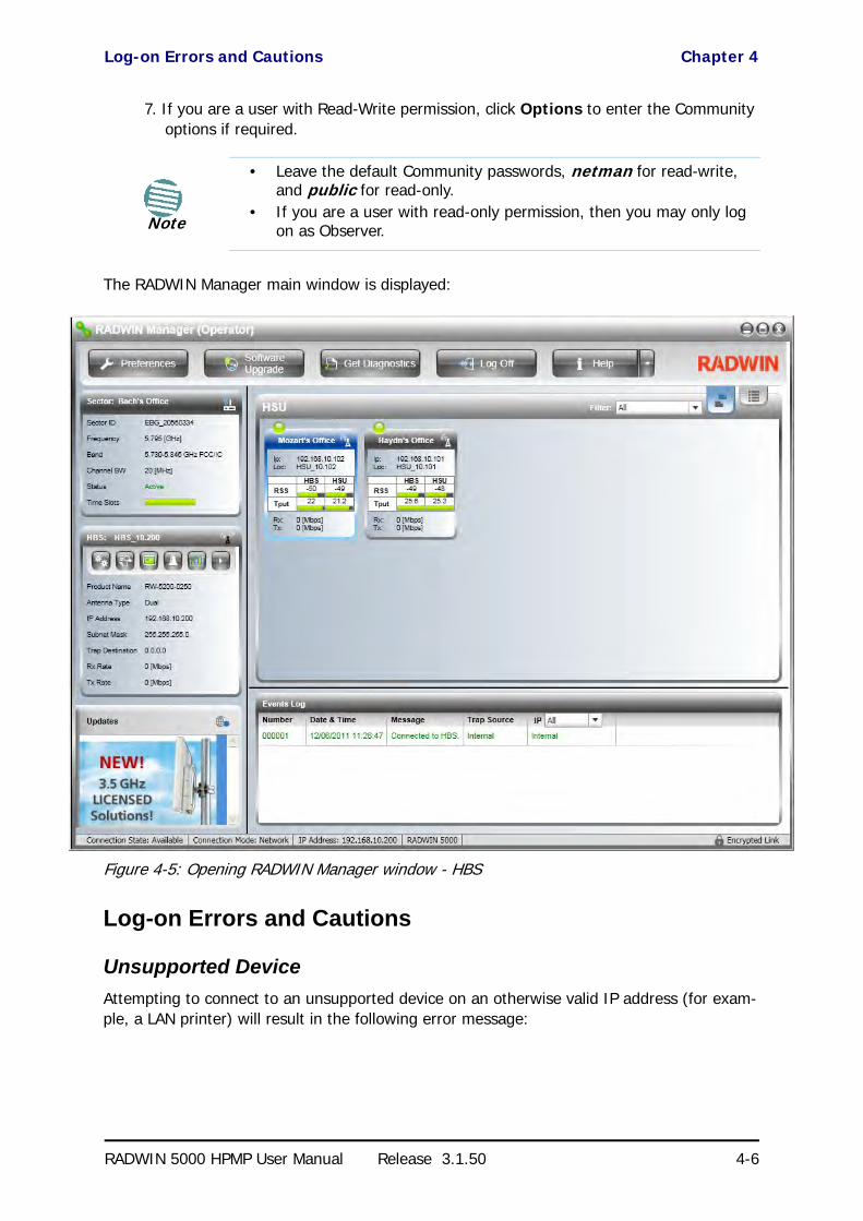
Log-on Errors and Cautions Chapter 4
RADWIN 5000 HPMP User Manual Release 3.1.50 4-6
7. If you are a user with Read-Write permission, click Options to enter the Community options if required.
The RADWIN Manager main window is displayed:
Figure 4-5: Opening RADWIN Manager window - HBS
Log-on Errors and Cautions
Unsupported Device
Attempting to connect to an unsupported device on an otherwise valid IP address (for exam-ple, a LAN printer) will result in the following error message:
Note
• Leave the default Community passwords, netman for read-write, and public for read-only.
• If you are a user with read-only permission, then you may only log on as Observer.

Incorrect IP Address Chapter 4
RADWIN 5000 HPMP User Manual Release 3.1.50 4-7
Figure 4-6: Unsupported device message
Incorrect IP Address
If the IP address chosen is invalid or the sector is unreachable, the following error message will be displayed:
Figure 4-7: Unreachable device message
In both of the above situations, if you click No, you will see a warning graphic alongside the IP Address field.
Incorrect Password
If you type an incorrect password in the Login window, you will see a warning graphic alongside the password field.
Invalid Read/Write Community String
This will result in the same message as shown in Figure 4-7.
Exploring the RADWIN Manager Main Window - HBS
The following sections describe the panels of main window shown in Figure 4-5.

HBS Main Button Menu Chapter 4
RADWIN 5000 HPMP User Manual Release 3.1.50 4-8
HBS Main Button Menu
Figure 4-8: HBS main button menu
Sector Status Panel
The sector level information is shown here. There is nothing that can be changed for an active sector. The parameters are set before the base station is activated and are duplicated for each HSU in the sector.
Figure 4-9: Sector Status panel
The last two items are of special interest: The Status (shown as Active) indicates whether the HBS has been activated or not. The Time Slots bar indicates how many out of 16 time slots, have been allocated to HSUs. Allocation of time slots between HSU provides a basic form of prioritization between them. Normally you would not leave unallocated time slots unless you intended to add more HSUs. Every HSU requires at least one time slot.
Base Station Panel
The displayed items in the Base Station panel are straight forward.
Table 4-4: HBS main button bar functions
Menu Item Purpose Reference
Preferences
Monitor - File location, interval and throughput units page 4-18
Events - Color coding for events log and events log file location page 4-19
Advanced - Enable/disable check for updates, monitoring interval and time-out page 4-20
Software Upgrade Perform software upgrade for a sector Chapter 11
Get Diagnostics Run and store diagnostics for all or some members of a sector Chapter 8
Log Off Return to log-on window
Help side arrow
Link Budget Calculator Chapter 16
Check Updates
About
Help Button View this User Manual
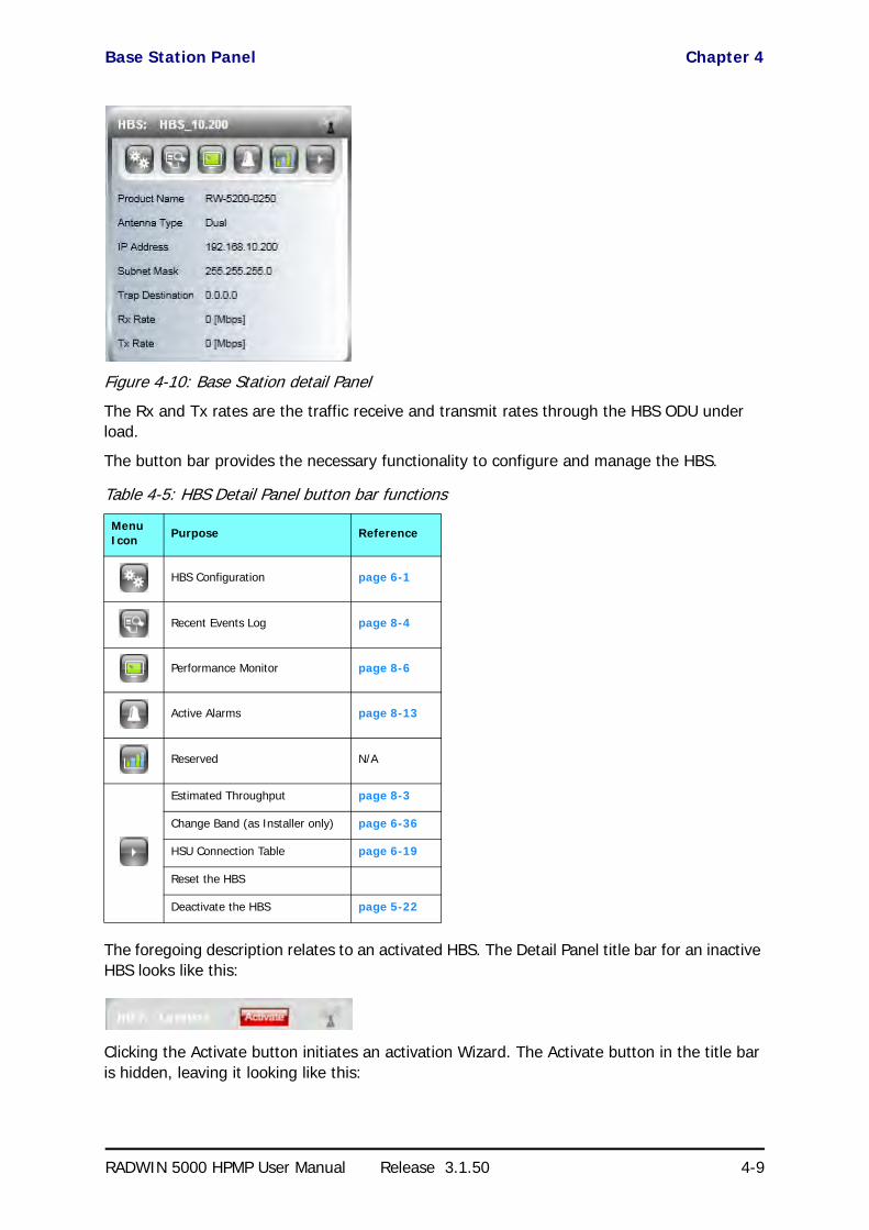
Base Station Panel Chapter 4
RADWIN 5000 HPMP User Manual Release 3.1.50 4-9
Figure 4-10: Base Station detail Panel
The Rx and Tx rates are the traffic receive and transmit rates through the HBS ODU under load.
The button bar provides the necessary functionality to configure and manage the HBS.
The foregoing description relates to an activated HBS. The Detail Panel title bar for an inactive HBS looks like this:
Clicking the Activate button initiates an activation Wizard. The Activate button in the title bar is hidden, leaving it looking like this:
Table 4-5: HBS Detail Panel button bar functions
Menu Icon Purpose Reference
HBS Configuration page 6-1
Recent Events Log page 8-4
Performance Monitor page 8-6
Active Alarms page 8-13
Reserved N/A
Estimated Throughput page 8-3
Change Band (as Installer only) page 6-36
HSU Connection Table page 6-19
Reset the HBS
Deactivate the HBS page 5-22
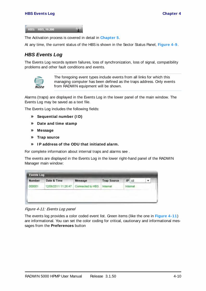
HBS Events Log Chapter 4
RADWIN 5000 HPMP User Manual Release 3.1.50 4-10
The Activation process is covered in detail in Chapter 5.
At any time, the current status of the HBS is shown in the Sector Status Panel, Figure 4-9.
HBS Events Log
The Events Log records system failures, loss of synchronization, loss of signal, compatibility problems and other fault conditions and events.
Alarms (traps) are displayed in the Events Log in the lower panel of the main window. The Events Log may be saved as a text file.
The Events Log includes the following fields:
» Sequential number (ID)
» Date and time stamp
» Message
» Trap source
» IP address of the ODU that initiated alarm.
For complete information about internal traps and alarms see .
The events are displayed in the Events Log in the lower right-hand panel of the RADWIN Manager main window:
Figure 4-11: Events Log panel
The events log provides a color coded event list. Green items (like the one in Figure 4-11) are informational. You can set the color coding for critical, cautionary and informational mes-sages from the Preferences button
Note
The foregoing event types include events from all links for which this managing computer has been defined as the traps address. Only events from RADWIN equipment will be shown.

HBS Main Window - HSUs Panel Chapter 4
RADWIN 5000 HPMP User Manual Release 3.1.50 4-11
HBS Main Window - HSUs Panel
Figure 4-12: HBS Main Window (Reduced) - up to 16 HSUs
The following case has colored fields indicating a problem requiring your attention:
Figure 4-13: HBS Main Window (Reduced) - indicating a problem
If you mouse-over the colored RSS area, you will receive a tool tip telling you that RSS for Radio 1 is higher than for Radio 2, or something similar.
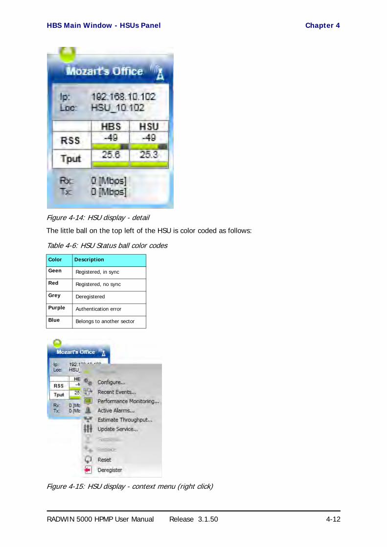
HBS Main Window - HSUs Panel Chapter 4
RADWIN 5000 HPMP User Manual Release 3.1.50 4-12
Figure 4-14: HSU display - detail
The little ball on the top left of the HSU is color coded as follows:
Figure 4-15: HSU display - context menu (right click)
Table 4-6: HSU Status ball color codes
Color Description
Geen Registered, in sync
Red Registered, no sync
Grey Deregistered
Purple Authentication error
Blue Belongs to another sector

Exploring the RADWIN Manager Main Window - HSU Chapter 4
RADWIN 5000 HPMP User Manual Release 3.1.50 4-13
Figure 4-16: HSU On HBS display - extract. Scroll right for more HSU fields
The button bar in Figure 4-16 follows the same pattern as the context menu in Figure 4-15.
Exploring the RADWIN Manager Main Window - HSU
You may log on to an HSU over the air from a HBS or by directly connecting a Managing Com-puter to the HSU PoE. You can log on over the air to any registered HSU. The HSU main win-dow is different from the HBS main window, however it uses the same GUI and the same names for common fields.
Table 4-7: HSU main window detail display context menu and button bar functions
Menu Item Menu Icon Purpose Reference
Register Register a HSU to a sector page 5-17
Configure Site configuration for the HSU page 6-20
Recent Events Recent events log per HSU page 8-4
Performance Monitoring
Performance Monitoring per HSU page 8-6
Active Alarms Display Active Alarms page 8-13
Estimate Throughput
Estimate throughput per HSU page 8-3
Update ServiceService evaluation and Time Slot allocation per HSU; also MIMO/Diversity selection
page 6-34
Suspend ... Suspend Service page 6-35
Replace Replace a HSU page 6-31
Reset Reset the HSU
Deregister Deregister the HSU page 5-22

Logging on to an HSU Chapter 4
RADWIN 5000 HPMP User Manual Release 3.1.50 4-14
Logging on to an HSU
You can log on to a HSU of an established sector. The log on procedure is the same as for a HBS. Suppose we log on to HSU with IP address 10.103.7.6: We initially receive the following caution:
Figure 4-17: Logging on to an HSU
Upon clicking OK to dismiss the caution, we get a variation of the previous main window:

Logging on to an HSU Chapter 4
RADWIN 5000 HPMP User Manual Release 3.1.50 4-15
Figure 4-18: Opening RADWIN Manager window - HSU
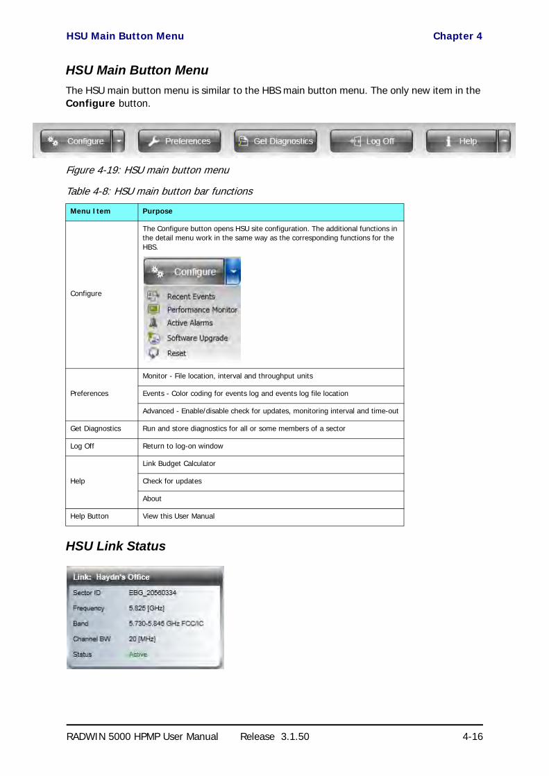
HSU Main Button Menu Chapter 4
RADWIN 5000 HPMP User Manual Release 3.1.50 4-16
HSU Main Button Menu
The HSU main button menu is similar to the HBS main button menu. The only new item in the Configure button.
Figure 4-19: HSU main button menu
HSU Link Status
Table 4-8: HSU main button bar functions
Menu Item Purpose
Configure
The Configure button opens HSU site configuration. The additional functions in the detail menu work in the same way as the corresponding functions for the HBS.
Preferences
Monitor - File location, interval and throughput units
Events - Color coding for events log and events log file location
Advanced - Enable/disable check for updates, monitoring interval and time-out
Get Diagnostics Run and store diagnostics for all or some members of a sector
Log Off Return to log-on window
Help
Link Budget Calculator
Check for updates
About
Help Button View this User Manual
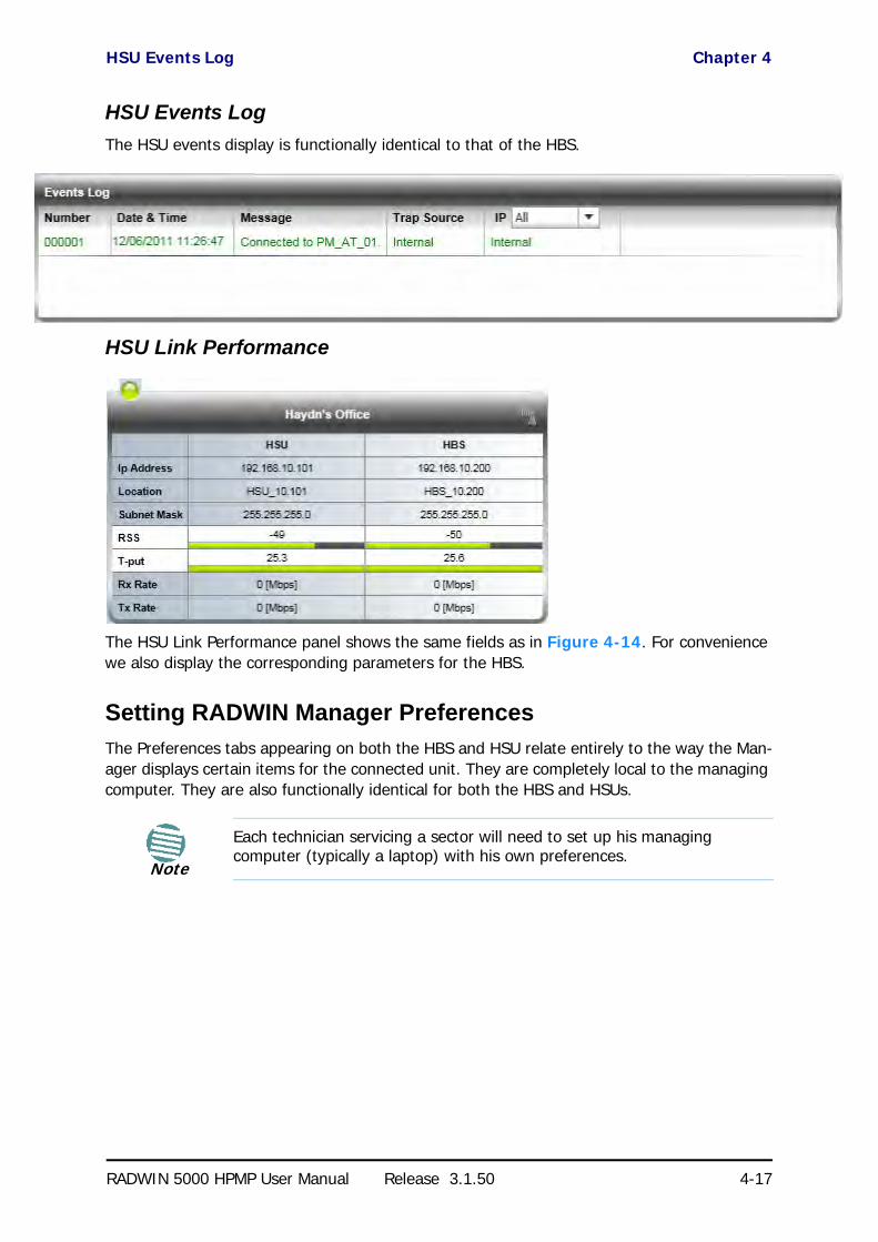
HSU Events Log Chapter 4
RADWIN 5000 HPMP User Manual Release 3.1.50 4-17
HSU Events Log
The HSU events display is functionally identical to that of the HBS.
HSU Link Performance
For convenience
The HSU Link Performance panel shows the same fields as in Figure 4-14. For convenience we also display the corresponding parameters for the HBS.
Setting RADWIN Manager Preferences
The Preferences tabs appearing on both the HBS and HSU relate entirely to the way the Man-ager displays certain items for the connected unit. They are completely local to the managing computer. They are also functionally identical for both the HBS and HSUs.
Note
Each technician servicing a sector will need to set up his managing computer (typically a laptop) with his own preferences.
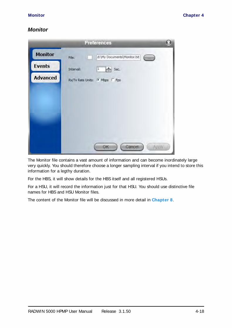
Monitor Chapter 4
RADWIN 5000 HPMP User Manual Release 3.1.50 4-18
Monitor
The Monitor file contains a vast amount of information and can become inordinately large very quickly. You should therefore choose a longer sampling interval if you intend to store this information for a legthy duration.
For the HBS, it will show details for the HBS itself and all registered HSUs.
For a HSU, it will record the information just for that HSU. You should use distinctive file names for HBS and HSU Monitor files.
The content of the Monitor file will be discussed in more detail in Chapter 8.

Events Chapter 4
RADWIN 5000 HPMP User Manual Release 3.1.50 4-19
Events
Here you may choose your own color coding for the Recent Event display (see Chapter 8).
You may also choose a location and file name for the events log for storage. These settings are again, per HBS or HSU. To avoid over-writing, you should use file names reflecting their source ODU.

Advanced Chapter 4
RADWIN 5000 HPMP User Manual Release 3.1.50 4-20
Advanced
Many alert messages in the RADWIN Manager have an option of the form “Do not show this message again”. These alert messages can be reverted to their default state (shown) by click-ing the Restore Alerts button. You will be asked to confirm:
If you are not connected to the Internet, disable the Check for updates check box. If you have a slow connection to the internet, you may wish to increase the monitoring and timeout intervals.
What Comes Next?
The purpose of this chapter was to offer an overview of a running RADWIN 5000 HPMP a sec-tor. The next three chapters will cover respectively, detailed sector setup considerations, sec-tor management and monitoring and diagnostics. The foregoing background should provide sufficient “signposts” to ensure that you do not become lost in the plethora of details required to commission and manage a fully operational sector.

RADWIN 5000 HPMP User Manual Release 3.1.50 5-1
Chapter 5
Installing the SectorScope of this Chapter
Chapter 4, offered an overview of a running Sector as motivation for the technical installa-tion details set out below.
Assuming that the Sector equipment is in place as described in earlier chapters, sector instal-lation has two phases:
• Configuring and activating the HBS
• Bringing up the HSUs - configuration and registration
The same RADWIN Manager program is used for both the HBS and the HSUs. Much of the process is common to both types of ODU. We will cover the HBS in detail; for the HSUs we will concentrate on those items which are different. In any event, where setup procedures are common we will point them out.
Concepts
A HBS out of the package, must be configured with
• Basic RF parameters such as frequency band, channel bandwidths and Sector ID• Networking parameters such as IP address, Subnet mask and default gateway
At this point, the HBS ODU is in an inactive state, powered up, configurable but not trans-mitting anything.
Upon activation, the HBS will commence transmitting and receiving packets related to sec-tor management only - that is no service. Activation and Deactivation are effected quite sim-ply by clicking a toggle button.
Assuming that the Sector HSUs are mounted aligned and powered up, the HSUs will dis-cover the HBS establishing links for management only. At this point the HSUs may be man-aged over the air.
As soon as the HSUs are configured to your satisfaction, you must register them on the HBS. Registration of an HSU enables service traffic between the HSU and the HBS.
During the registration process, you assign time slots to each HSU. A total of 16 time slots are available to each HBS to be distributed among the HSUs in the sector. The relative num-ber of time slots determines the relative amount of service each HSU will receive. Each HSU

Workflow Chapter 5
RADWIN 5000 HPMP User Manual Release 3.1.50 5-2
receives at least one time slot. To disable an HSU you must deregister it. (A suspend mech-anism is also available, to suspend service on an HSU for a limited period.)
For each registered HSU, you can set separately, the uplink and downlink Maximum Infor-mation Rate (MIR) in Mbps or leave it at Best Effort.
You may also manage an HSU Connection table to enable and disable connectivity between HSUs in a sector.
Workflow
In this chapter, we assume that you are familiar with the material of Chapter 4. We will con-centrate on setup workflow assuming that you are familiar with GUI.
Prior to commencing, you should have written sector plan along the lines of Table 4-2.
Configuring the Sector out of the Box - IP Addresses
The default log-on IP address for all ODUs in the sector is the same: 10.0.0.120, Subnet Mask 255.0.0.0 and default gateway 0.0.0.0. To get the process started, set up the IP address on the network card on the managing computer to something like 10.0.0.100, Subnet Mask 255.255.255.0 and Default Gateway 0.0.0.0.
Ensure that you have a direct LAN connection to the ODU, run the RADWIN Manager and log-on to it.
Figure 5-1: Logging on with factory default IP address
Alternatively, you can log on using Local Connection without need to change your Network Interface Card address:
Figure 5-2: Logging on with Local Connection

Configuring the Sector out of the Box - IP Addresses Chapter 5
RADWIN 5000 HPMP User Manual Release 3.1.50 5-3
Here is the main display:
Warning
• The Local Connection method uses broadcast packets to “discover” the attached ODU
• If you log on using Local Connection, but your physical connection is not local (i.e. anything other than a direct connection between the managing computer and the IDU), then any configuration you carry out may affect other links in the network. Do not do this!
• Do not carry out this procedure using a multi homed managing com-puter also connected to a network. It will flood the network with broadcast packets. Further, it will throw any other links on the net-work into Installation or Inactive mode.
• Network log on (IP address to the ODU) is recommended.

Configuring the Sector out of the Box - IP Addresses Chapter 5
RADWIN 5000 HPMP User Manual Release 3.1.50 5-4
Figure 5-3: Main window for un-configures HBS ODU
Notice the red icon on the top left corner of the window. It will change to green as soon as the HBS is configured and activated.
To pre-configure the HBS and HSUs prior to deployment in the field:
1. Click the configuration button . The Base Station site configuration widow opens:

Configuring the Sector out of the Box - IP Addresses Chapter 5
RADWIN 5000 HPMP User Manual Release 3.1.50 5-5
Figure 5-4: Site Configuration prior to definition
2. Enter the Name, Contact and Location field. For what follows we will use the values used in Chapter 4. To ensure that your data is captured use the Apply button after each step.
3. Click the Management tab.

Configuring the Sector out of the Box - IP Addresses Chapter 5
RADWIN 5000 HPMP User Manual Release 3.1.50 5-6
Figure 5-5: Definition of IP address done here
4. Enter the IP address, Subnet Mask and default Gateway and then click OK. You are offered a warning:
5. Click Yes. The dialog is dismissed and you are returned to the main window. The Sector Status panel indicated (as expected), Device unreachable.
6. Disconnect the HBS ODU and repeat steps 1 to 6 for each HSU in the sector. The opening windows will look different, but the HSU site configuration dialogs will be the same.

Activating the HBS Chapter 5
RADWIN 5000 HPMP User Manual Release 3.1.50 5-7
At this point you should field-install the units according to the guidelines in Chapter 3. You should now revert your network card to the Sector Subnet.
Activating the HBS
With all the units in place, log on to the HBS using the new IP address. The main window looks like this:
Figure 5-6: HBS ready for configuration and activation
Activating the HBS enables it to be discovered by the HSUs. An Activation Wizard will guide you through the process.
To activate an HBS:
1. Click the Activate button. The Activation Wizard opens.

Activating the HBS Chapter 5
RADWIN 5000 HPMP User Manual Release 3.1.50 5-8
2. Click Next:
Enter the Sector ID. Choose it carefully particularly if you are using collocated HBSs for extra coverage. The Sector Name and Location are convenience items but should be used to ensure that the sector is documented and easily identifiable in your RF planning. The Link Password may also be changed by clicking Change:
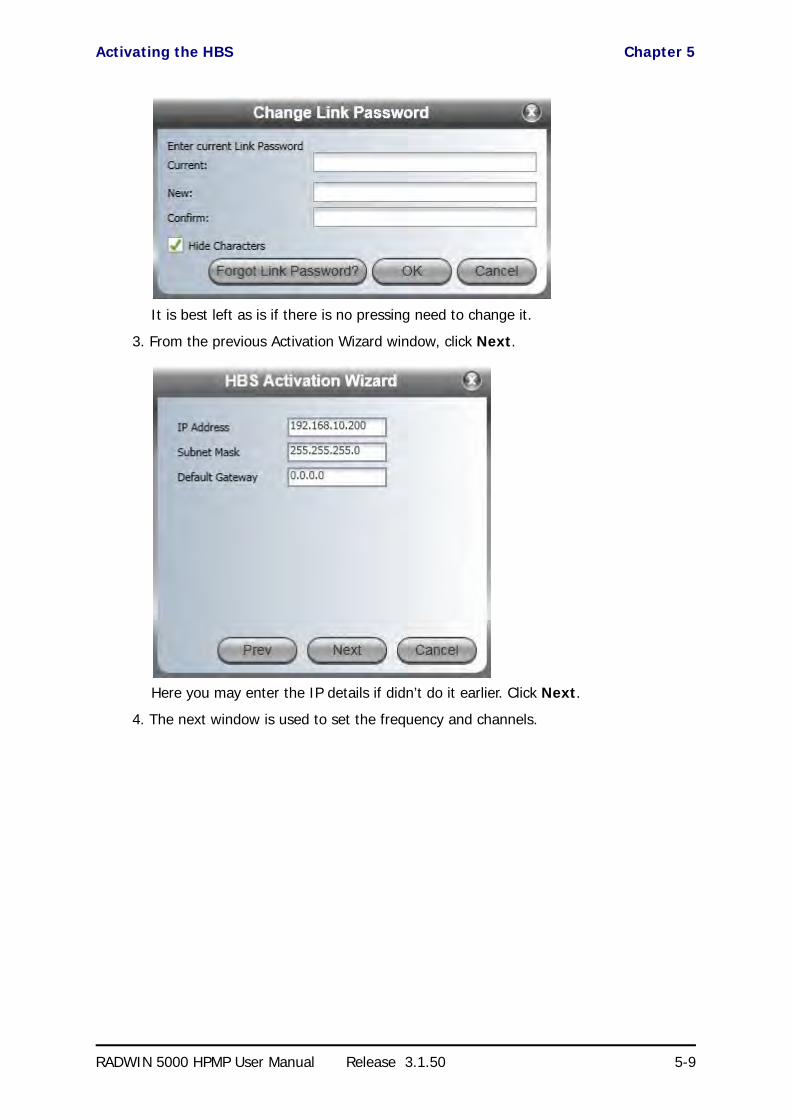
Activating the HBS Chapter 5
RADWIN 5000 HPMP User Manual Release 3.1.50 5-9
It is best left as is if there is no pressing need to change it.
3. From the previous Activation Wizard window, click Next.
Here you may enter the IP details if didn’t do it earlier. Click Next.
4. The next window is used to set the frequency and channels.

Activating the HBS Chapter 5
RADWIN 5000 HPMP User Manual Release 3.1.50 5-10
Choosing Other allows you to choose a frequency by hand. Otherwise, you may choose from a drop-down list of available frequencies:
5. Click the Automatic Channel Select box:

Activating the HBS Chapter 5
RADWIN 5000 HPMP User Manual Release 3.1.50 5-11
You can perform a customized channel selection or click Select All to check all the channel boxes as shown:”
6. Click Next. The Antenna type and Tx Power window is presented:

Activating the HBS Chapter 5
RADWIN 5000 HPMP User Manual Release 3.1.50 5-12
The choice of Tx Power, antenna gain and cable loss (between the radio and the antenna) determines the EIRP and is affected by such considerations as radio limita-tions and regulatory restrictions.
Before completing antenna installation, you might like to consider the background information about setting antenna parameters, in Appendix E:
Choose your Antenna Type, Required Tx Power, Antenna Gain and Cable Loss. We will set Required Tx Power to 6 dBm for our example. Click Next.
7. The Summary window of the Wizard is displayed.
Warning
When setting Required Tx Power, it is your responsibility to chose a value in compliance with your local regulations.
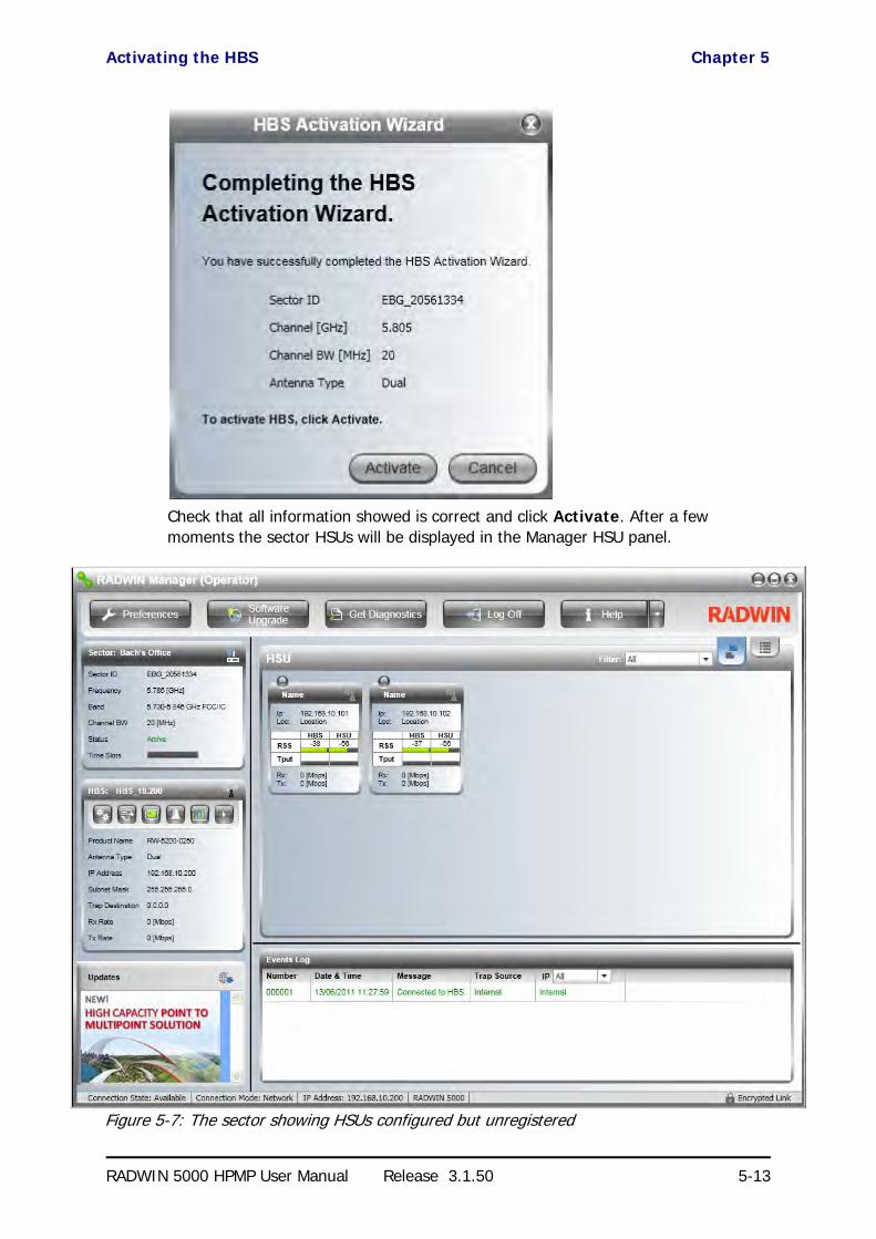
Activating the HBS Chapter 5
RADWIN 5000 HPMP User Manual Release 3.1.50 5-13
Check that all information showed is correct and click Activate. After a few moments the sector HSUs will be displayed in the Manager HSU panel.
Figure 5-7: The sector showing HSUs configured but unregistered

Configuring the HSUs for Service Chapter 5
RADWIN 5000 HPMP User Manual Release 3.1.50 5-14
At this point, the HSUs can communicate for management but not for service.
You may see that an HSUs has its RSS entry shaded yellow. Shading of this type indicates a problem. To see what it is, mouse-over the shaded area. A tool tip appears displaying a mes-sage:
You should correct the problem before proceeding.
Further, you may have observed that operating frequency 5.785 GHz shown, is not what we chose (5.805 GHz). The HBS tries to optimize the frequency to minimize the kind of problem displayed above.
Configuring the HSUs for Service
The HSU activities described in this section, may be carried out any time - regardless of whether or not the HSU is registered for service or not. These activities include among other things, setting the Location, Contact and Name. We have chosen to do them here since they reflect the workflow required to set up an operational sector.
To pre-configure a HSU for service:
1. Right click an HSU to get its context menu:
2. Click Configure. The Configuration dialog is displayed. Enter a Name Contact and Location:
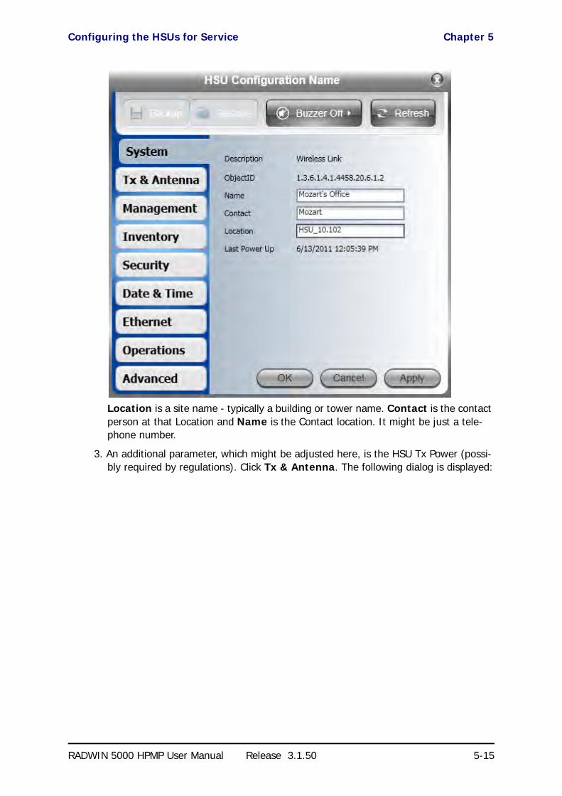
Configuring the HSUs for Service Chapter 5
RADWIN 5000 HPMP User Manual Release 3.1.50 5-15
Location is a site name - typically a building or tower name. Contact is the contact person at that Location and Name is the Contact location. It might be just a tele-phone number.
3. An additional parameter, which might be adjusted here, is the HSU Tx Power (possi-bly required by regulations). Click Tx & Antenna. The following dialog is displayed:

Configuring the HSUs for Service Chapter 5
RADWIN 5000 HPMP User Manual Release 3.1.50 5-16
4. Set the Antenna Type, Required Tx Power, Antenna Gain and Cable Loss as required. For our example, we set Tx Power to 5 dBm.
5. Click OK and repeat the last four steps for each HSU in the sector. Here is the out-come for our example:

Registering the HSUs for Service Chapter 5
RADWIN 5000 HPMP User Manual Release 3.1.50 5-17
As a partial alternative method, you may enter the Name and Location fields during Regis-tration.
Registering the HSUs for Service
We continue our illustration using HSU at HSU_10.102.
Note
If you do not see the changes as shown, a hard reset of the HSUs will cause them to appear.

Registering the HSUs for Service Chapter 5
RADWIN 5000 HPMP User Manual Release 3.1.50 5-18
To register an HSU for service:
1. Right click an HSU to get its context menu:
2. Click Register... The Registration window opens:
3. You may edit or add the site Name and Location.
4. If you are using Dual Antennas, you may check the MIMO or Diversity antenna mode. The choice is HSU specific. For further details about MIMO/Diversity antenna mode, see Appendix E.

Registering the HSUs for Service Chapter 5
RADWIN 5000 HPMP User Manual Release 3.1.50 5-19
5. Click the Evaluate button. Service evaluation takes a few seconds during which the window is darkened and inactive. Upon completion you may assign time slots to the HSU:
Figure 5-8: HSU Registration dialog
6. Click the number of time slots to be allocated to the HSU.
The Register button is now enabled.

Registering the HSUs for Service Chapter 5
RADWIN 5000 HPMP User Manual Release 3.1.50 5-20
7. Use the sliders to set uplink and downlink MIR. You may defer this and carry it out using the HSU Configure option. The MIR acts a s a “throttle”.
8. Click Register it to complete the process. Here is the result for our example”
Observe that the registered HSU LED is now green and that the Time Slots bar on the left reflects the proportion of time slots allocated.
9. Repeat steps 1 to 8 for other HSUs. Here is the result for our example:

Choosing Diversity Antenna Mode During Registration Chapter 5
RADWIN 5000 HPMP User Manual Release 3.1.50 5-21
Figure 5-9: Fully functional sector
Choosing Diversity Antenna Mode During Registration
Suppose that in Figure 5-8 for HSU_10.102 we had chosen Diversity mode, the outcome would look like this:
The throughput on this HSU has dropped to about half of its previous value. The other HSU is left unchanged.
This underlines the flexibility of the RADWIN 5000 HPMP system which enables HSUs to be independently configured depending on their particular location.

Deactivating the HBS Chapter 5
RADWIN 5000 HPMP User Manual Release 3.1.50 5-22
Deactivating the HBS
From the HBS button bar, click the right hand button followed by Deactivate.
You ware offered a cautionary message:
If you proceed, the HBS display will change to reflect the deactivated state:
Deregistering a HSU
A HSU may be deregistered by using the Deregister entry in a HSU context menu or using the
button from a HSU button bar.
Where has my HSU gone? Chapter 5
RADWIN 5000 HPMP User Manual Release 3.1.50 5-23
Where has my HSU gone?
Suppose that you installed two collocated HBSs with contiguous sectors. It is possible that an HSU located close to the common sector boundary may “discover” the wrong HBS. A HSU can be “forced” across to another HBS by changing its Sector ID to that of the required HBS. The method for doing this is covered in Chapter 7.

RADWIN 5000 HPMP
Point to Multipoint Broadband Wireless
USER MANUAL
RELEASE 3.1.50
Part 3: Sector Management
UM 5000-3150/06.11

RADWIN 5000 HPMP User Manual Release 3.1.50 6-1
Chapter 6
Managing the Sector fromthe HBS
Scope of this Chapter
This chapter deals with managing the sector from the HBS. It covers HBS Configuration and HSU Configuration from the HBS. HSU direct or over-the-air configuration is a little different and is covered in Chapter 7.
A Configuration window is available for both the HBS and the HSUs to change setting without necessarily dropping service. Nevertheless care must be exercised when changing them. By way of example, changing an IP address will possibly make a unit unreachable. It is neces-sary however to have this function in the Configuration window since it is required to initially set up the unit.
Configuring a HBS
Configuration Menu Buttons
Open the Configuration window.
The Backup and Restore buttons provide for backup and restore of the HBS software.
The Refresh button restores the current window to its previous state abandoning any changes you made, provided that you did not click Apply or OK.
We will work through each of the Configuration tabs in turn:
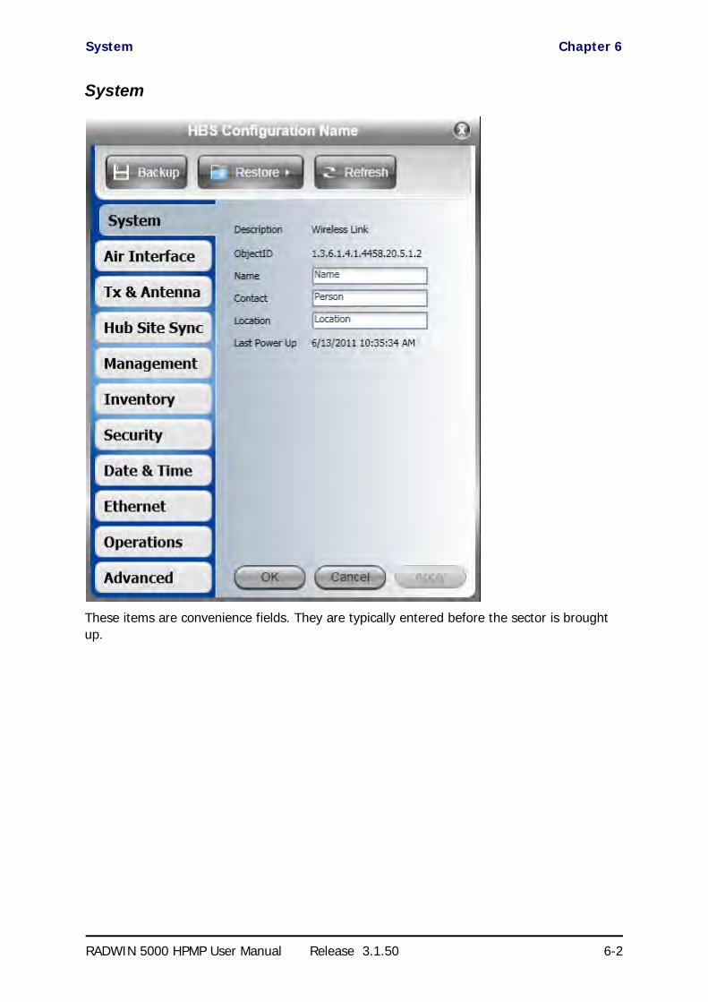
System Chapter 6
RADWIN 5000 HPMP User Manual Release 3.1.50 6-2
System
These items are convenience fields. They are typically entered before the sector is brought up.

Air Interface Chapter 6
RADWIN 5000 HPMP User Manual Release 3.1.50 6-3
Air Interface
This panel has the same functionality as the corresponding window in the Activation Wizard (see Chapter 5). Changing the Sector ID will “percolate” to all registered HSUs. It will of course, be “picked up” by newly installed and registered HSUs.
Channel Bandwidth and Channel Selection changes will all be sector-wide.
Tx and Antenna
This tab is available for both the HBS and HSUs. It has the same meaning in both cases.

Tx and Antenna Chapter 6
RADWIN 5000 HPMP User Manual Release 3.1.50 6-4
For the HBS, changes made here may affect link quality and in the case of antenna type, cause a sector re-sync.
Changing the antenna type for a HSU will cause a re-sync to that site only.

Hub Site Sync [HSS] Chapter 6
RADWIN 5000 HPMP User Manual Release 3.1.50 6-5
Hub Site Sync [HSS]
The External Pulses detected in this example, come from a collocated RADWIN 2000 ODU configured as Hub Sync Master. (A WinLink 1000 would have done just as well.) To enable HSS, check the Enabled check box.
Ensure that the correct Operational state is selected - in our example, Hub Site Client - Continue Tx. Click Apply or OK to enable HSS.
.See Chapter 9 for further detail about HSS.
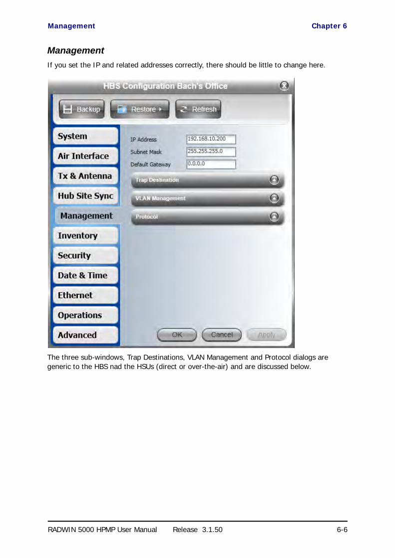
Management Chapter 6
RADWIN 5000 HPMP User Manual Release 3.1.50 6-6
Management
If you set the IP and related addresses correctly, there should be little to change here.
The three sub-windows, Trap Destinations, VLAN Management and Protocol dialogs are generic to the HBS nad the HSUs (direct or over-the-air) and are discussed below.
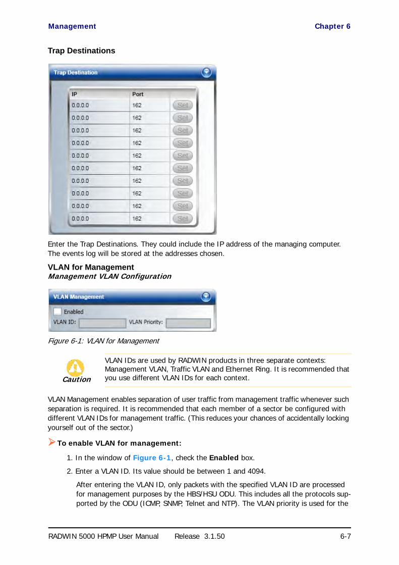
Management Chapter 6
RADWIN 5000 HPMP User Manual Release 3.1.50 6-7
Trap Destinations
Enter the Trap Destinations. They could include the IP address of the managing computer. The events log will be stored at the addresses chosen.
VLAN for ManagementManagement VLAN Configuration
Figure 6-1: VLAN for Management
VLAN Management enables separation of user traffic from management traffic whenever such separation is required. It is recommended that each member of a sector be configured with different VLAN IDs for management traffic. (This reduces your chances of accidentally locking yourself out of the sector.)
To enable VLAN for management:
1. In the window of Figure 6-1, check the Enabled box.
2. Enter a VLAN ID. Its value should be between 1 and 4094.
After entering the VLAN ID, only packets with the specified VLAN ID are processed for management purposes by the HBS/HSU ODU. This includes all the protocols sup-ported by the ODU (ICMP, SNMP, Telnet and NTP). The VLAN priority is used for the
Caution
VLAN IDs are used by RADWIN products in three separate contexts: Management VLAN, Traffic VLAN and Ethernet Ring. It is recommended that you use different VLAN IDs for each context.

Inventory Chapter 6
RADWIN 5000 HPMP User Manual Release 3.1.50 6-8
traffic sent from the ODU to the managing computer. Using VLAN for management traffic affects all types of management connections (local, network and over the air).
3. Enter a Priority number between 0 and 7.
4. Change the VLAN ID and Priority of the managing computer NIC to be the same as those of steps 2 and 3 respectively.
5. Click Apply or OK.
Lost or forgotten VLAN ID
If the VLAN ID is forgotten or there is no VLAN traffic connected to the ODU, then reset the relevant ODU.
During the first two minutes of connection, the ODU uses management packets both with and without VLAN. You may use this period to reconfigure the VLAN ID and priority.
Supported Protocols
For a sector managed as part of a network, direct access to a HBS/HSU using Telnet is consid-ered to be a security breach. Telnet access may be enabled or disabled by clicking the Proto-col tab and enabling/disabling Telnet access using the Telnet check-box:
For further details about Telnet access see page 6-40.
Telnet access mode when available, is site specific. If for example, you want Telnet access from specific sector members, you should enable it for these sites and disable it elsewhere.
Inventory
You might like to capture or copy the information here:
Caution
Changing this parameter causes the RADWIN Manager to immediately disconnect. To avoid inconvenience, you should verify the change by setting the VLAN only to one ODU, and only after verifying proper management operation, change the other ODU VLAN setting.
Note
SNMP access is on by default for RADWIN 5000 HPMP and cannot be disabled.
Note
If Telnet access mode poses a general security risk, you must disable it for each sector member separately.

Security Chapter 6
RADWIN 5000 HPMP User Manual Release 3.1.50 6-9
The Inventory information will be required by Customer Support should you require assis-tance.
Security
This section applies to both the HBS and HSUs unless stated otherwise.

Security Chapter 6
RADWIN 5000 HPMP User Manual Release 3.1.50 6-10
The Security dialog enables you to change the Link Password and the SNMP Community strings.
Changing the Link Password
This item is available as follows:
• Always at the HBS• Isolated HSU
• Never for an active HSU
Otherwise, it works the same way as the corresponding item on page 5-9.
RADWIN Manager Community Strings
The ODU communicates with the RADWIN Manager using SNMPv1 protocol. The protocol defines three types of communities:
• Read-Only for retrieving information from the ODU
n this section, ODU may be either a HBS or a HSU.

Security Chapter 6
RADWIN 5000 HPMP User Manual Release 3.1.50 6-11
• Read-Write to configure and control the ODU• Trap used by the ODU to issue traps.
The Community string must be entered at log on. You must know the password and the cor-rect Community string to gain access to the system. You may have read-only privileges. It is not possible to manage the ODU if the read-write or the read Community values are forgot-ten. A new Community value may be obtained from RADWIN Customer Support for the pur-pose of setting new Community. You must also have available the serial number or the MAC address of the ODU.
The read-write Community strings and read-only Community strings have a minimum of five alphanumeric characters. (bru1 and bru4097 are not permitted). Changing the trap Com-munity is optional and is done by clicking the check box.
Editing Community Strings
When editing these strings, both read-write and read-only communities must be defined.
Upon logging on for the first time, use the following as the current Community:
• For Read-Write Community, use netman. • For Read-Only Community, use public.• For Trap Community, use public
To change a Community string:
1. Type the current read-write Community (default is netman).
2. Choose the communities to be changed by clicking the check box.
3. Type the new Community string and re-type to confirm. A community string must contain at least five and no more than 32 characters excluding SPACE, TAB, and any of “>#@|*?;."
4. Click OK to save.

Security Chapter 6
RADWIN 5000 HPMP User Manual Release 3.1.50 6-12
Figure 6-2: Changing the Community String
Forgotten Community string
If the read-write Community string is unknown, an alternative Community key can be used. The alternative Community key is unique per ODU and can be used only to change the Com-munity strings. The alternative Community key is supplied with the product, and should be kept in a safe place.
If both the read-write Community and the alternative Community key are unavailable, then an alternative Community key can be obtained from RADWIN Customer Support using the ODU serial number or MAC address. The serial number is located on the product label. The serial number and the MAC address are displayed in the Site Configuration inventory tab.
When you have the alternative Community key, click the Forgot Community button and enter the Alternative Community key (Figure 6-3). Then change the read-write Community string.

Date and Time Chapter 6
RADWIN 5000 HPMP User Manual Release 3.1.50 6-13
Figure 6-3: Alternative Community Dialog box
Date and TimeSetting the Date and Time
The ODU maintains a date and time. The date and time should be synchronized with any Net-work Time Protocol (NTP) version 3 compatible server.
During power-up the ODU attempts to configure the initial date and time using an NTP Server. If the server IP address is not configured or is not reachable, a default time is set.
When configuring the NTP Server IP address, you should also configure the offset from the Universal Coordinated Time (UTC). If there is no server available, you can either set the date and time, or you can set it to use the date and time from the managing computer. Note that manual setting is not recommended since it will be overridden by a reset, power up, or syn-chronization with an NTP Server.
To set the date and time:
1. Determine the IP address of the NTP server to be used.
2. Test it for connectivity using the command (Windows XP), for example:
w32tm /stripchart /computer:216.218.192.202
Note
The NTP uses UDP port 123. If a fire wall is configured between the ODU and the NTP Server this port must be opened.
It can take up to 8 minutes for the NTP to synchronize the ODU date and time.
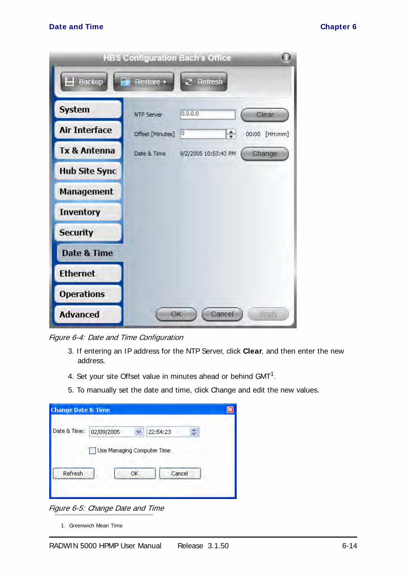
Date and Time Chapter 6
RADWIN 5000 HPMP User Manual Release 3.1.50 6-14
Figure 6-4: Date and Time Configuration
3. If entering an IP address for the NTP Server, click Clear, and then enter the new address.
4. Set your site Offset value in minutes ahead or behind GMT1.
5. To manually set the date and time, click Change and edit the new values.
Figure 6-5: Change Date and Time
1. Greenwich Mean Time

Ethernet Chapter 6
RADWIN 5000 HPMP User Manual Release 3.1.50 6-15
6. Click OK to return to the Configuration dialog.
Ethernet
The only field you may change here is the HBS aging time. The HBS works in Bridge Mode. In Bridge mode the ODU performs both learning and aging, forwarding only relevant packets over the sector. The aging time of the ODU is by default, 300 seconds.
Figure 6-6: Setting HBS Aging Time
Operations
This section applies to both HBSs and HSUs.
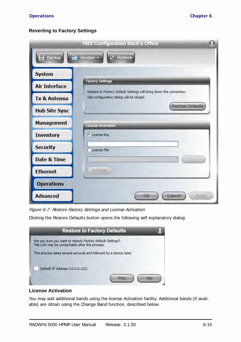
Operations Chapter 6
RADWIN 5000 HPMP User Manual Release 3.1.50 6-16
Reverting to Factory Settings
Figure 6-7: Restore Factory Settings and License Activation
Clicking the Restore Defaults button opens the following self explanatory dialog:
License Activation
You may add additional bands using the license Activation facility. Additional bands (if avail-able) are obtain using the Change Band function, described below.
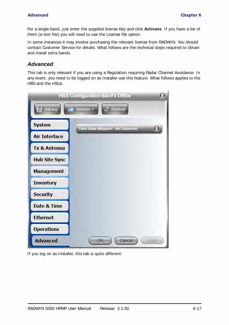
Advanced Chapter 6
RADWIN 5000 HPMP User Manual Release 3.1.50 6-17
For a single band, just enter the supplied license Key and click Activate. If you have a list of them (a text file) you will need to use the License file option.
In some instances it may involve purchasing the relevant license from RADWIN. You should contact Customer Service for details. What follows are the technical steps required to obtain and install extra bands.
Advanced
This tab is only relevant if you are using a Regulation requiring Radar Channel Avoidance. In any event, you need to be logged on as Installer use this feature. What follows applies to the HBS and the HSUs.
If you log on as Installer, this tab is quite different:

Advanced Chapter 6
RADWIN 5000 HPMP User Manual Release 3.1.50 6-18
Figure 6-8: False Radar Mitigation
DFS and False Radar MitigationAbout DFS
Under DFS frequency bands, it must be ensured that radio links do not interfere with certain radar systems in the 5 GHz band. If radar is detected, the radio link should move automati-cally to a frequency that does not interfere with the detected radar.
False Radar Mitigation
False Radar Mitigation capability is an advanced method to reduce or eliminate false radar detection and DFS triggering (“False positives”).
False radar detection can be caused by other radios transmissions or external interference that can be interpreted as true radar.
This option is active only in DFS frequency bands, 5.3/5.4 GHz FCC (HBS only) and 5.4/5.8GHz ETSI (HBS & HSU).
False Radar Mitigation is configured for:
• HBS (see Figure 6-8 above)
• HSU for ETSI bands only as in Figure 6-15 and Figure 7-5.
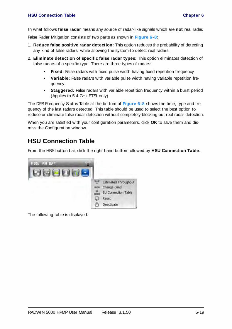
HSU Connection Table Chapter 6
RADWIN 5000 HPMP User Manual Release 3.1.50 6-19
In what follows false radar means any source of radar-like signals which are not real radar.
False Radar Mitigation consists of two parts as shown in Figure 6-8:
1. Reduce false positive radar detection: This option reduces the probability of detecting any kind of false radars, while allowing the system to detect real radars.
2. Eliminate detection of specific false radar types: This option eliminates detection of false radars of a specific type. There are three types of radars:
• Fixed: False radars with fixed pulse width having fixed repetition frequency• Variable: False radars with variable pulse width having variable repetition fre-
quency
• Staggered: False radars with variable repetition frequency within a burst period (Applies to 5.4 GHz ETSI only)
The DFS Frequency Status Table at the bottom of Figure 6-8 shows the time, type and fre-quency of the last radars detected. This table should be used to select the best option to reduce or eliminate false radar detection without completely blocking out real radar detection.
When you are satisfied with your configuration parameters, click OK to save them and dis-miss the Configuration window.
HSU Connection Table
From the HBS button bar, click the right hand button followed by HSU Connection Table.
The following table is displayed:

Configuring a HSU from the HBS Main Window Chapter 6
RADWIN 5000 HPMP User Manual Release 3.1.50 6-20
Figure 6-9: HSU Intercommunication
The green shaded squares show intercommunicating elements within the sector. MNG refers to management traffic which should always be open between HSUs and the HBS. LAN refers to service traffic between the HBS and the HSUs. As shown, the two HSUs may not communi-cate between themselves. Clicking the top white square would enable communication (via the HBS) between them.
You may in fact disable all traffic between the HBS and the HSUs and restore it using this device.
Configuring a HSU from the HBS Main Window
Right click a HSU for its context menu and click Configure to open the HSU Configuration window.
Configuration Menu Buttons
The Backup and Restore buttons have the same functionality as the corresponding buttons for the HBS. They provide for backup and restore of the HSU software.
The Buzzer button may set or mute the buzzer.
Recall that the buzzer tone is used for HSU antenna alignment.
The Refresh button restores the current window to its previous state abandoning any changes you made, provided that you did not click Apply or OK.

System Chapter 6
RADWIN 5000 HPMP User Manual Release 3.1.50 6-21
We will work through each of the Configuration tabs in turn:
System
Figure 6-10: HSU Configuration window (HBS)
These items are convenience fields. They are typically entered before the sector is brought up.

Tx & Antenna Chapter 6
RADWIN 5000 HPMP User Manual Release 3.1.50 6-22
Tx & Antenna
Figure 6-11: HSU Configuration - Setting antenna type and parameters
The remarks about changing the HBS parameters also apply here. Changing the antenna type will cause a re-sync between the HSU and the HBS.

Management Chapter 6
RADWIN 5000 HPMP User Manual Release 3.1.50 6-23
Management
Figure 6-12: HSU Configuration - IP addresses
The functionality is identical as that for the HBS.
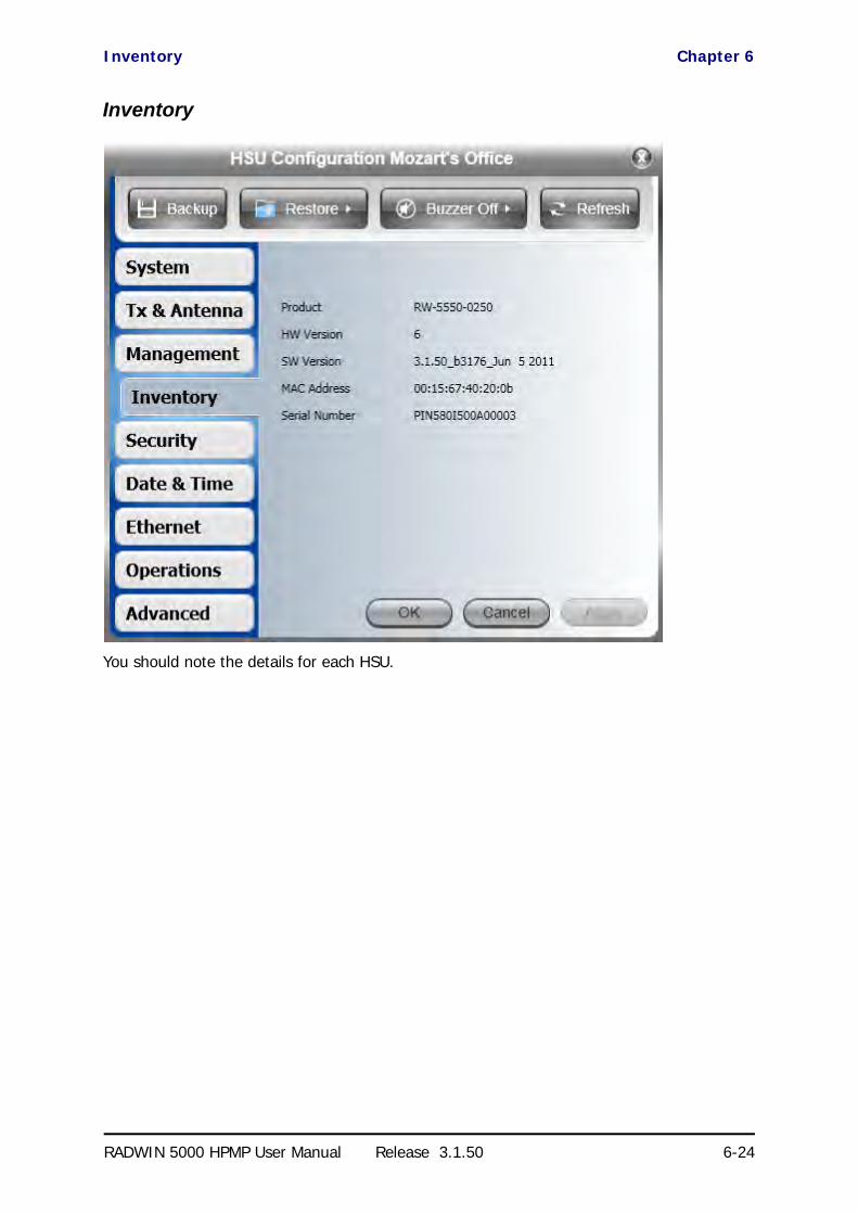
Inventory Chapter 6
RADWIN 5000 HPMP User Manual Release 3.1.50 6-24
Inventory
You should note the details for each HSU.

Security Chapter 6
RADWIN 5000 HPMP User Manual Release 3.1.50 6-25
Security
You may change the SNMP community strings only for the HSU from here. You cannot change the Link password from a HSU.

Date & Time Chapter 6
RADWIN 5000 HPMP User Manual Release 3.1.50 6-26
Date & Time
The functionality is identical as that for the HBS.

Ethernet Chapter 6
RADWIN 5000 HPMP User Manual Release 3.1.50 6-27
Ethernet
Maximum Information Rate
Figure 6-13: Setting the MIR
The Maximum Information Rate (MIR) was initially set during HSU Registration. You may change it here.

VLAN Configuration Chapter 6
RADWIN 5000 HPMP User Manual Release 3.1.50 6-28
VLAN Configuration
For Traffic VLAN configuration, see Chapter 12.

Operations Chapter 6
RADWIN 5000 HPMP User Manual Release 3.1.50 6-29
Operations
This functionality is identical as that for the HBS.

Advanced Chapter 6
RADWIN 5000 HPMP User Manual Release 3.1.50 6-30
Advanced
a
Figure 6-14: HSU Configuration - Advanced, as Operator

Replacing a HSU Chapter 6
RADWIN 5000 HPMP User Manual Release 3.1.50 6-31
Figure 6-15: Configuration - Advanced, as Installer
For a HSU, False Radar Mitigation is
• Required for ETSI DFS and the functionality is identical as that for the HBS
• Not supported for FCC DFS
Replacing a HSU
A defective HSU may be replaced by another HSU belonging to the sector provided that the replacement is not registered. Here is a typical scenario:
Figure 6-16: Unit 10.101 is down and unit 10.102 is available and not registered
Since the replacement procedure is a rather delicate process, we will step through it with a detailed example based on the scenario in Figure 6-16.
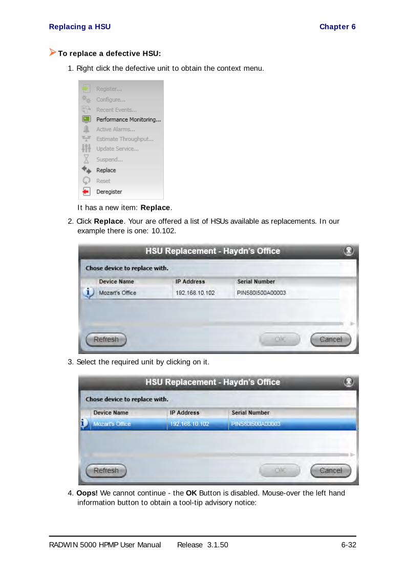
Replacing a HSU Chapter 6
RADWIN 5000 HPMP User Manual Release 3.1.50 6-32
To replace a defective HSU:
1. Right click the defective unit to obtain the context menu.
It has a new item: Replace.
2. Click Replace. Your are offered a list of HSUs available as replacements. In our example there is one: 10.102.
3. Select the required unit by clicking on it.
4. Oops! We cannot continue - the OK Button is disabled. Mouse-over the left hand information button to obtain a tool-tip advisory notice:

Replacing a HSU Chapter 6
RADWIN 5000 HPMP User Manual Release 3.1.50 6-33
5. Cancel the current dialog and right click 10.102. Use Configure | Tx & Antenna set the required antenna type (sse page 6-22). Here is the current situation:
Notice that although site 10.101 is down, it is still registered and its Time Slots are still reserved.
6. Repeat steps 1 to 3. Now the OK button is enabled:
7. Click OK. You are requested to accept your choice:

Updating HSU Services Chapter 6
RADWIN 5000 HPMP User Manual Release 3.1.50 6-34
8. Click OK. Doing this, de-registers your defective device (10.101) and registers the replacement (10.102).
9. Again, click OK. Here then, is the final situation:
Updating HSU Services
Choosing Update Services from a HSU context menu or clicking from the HSU button bar opens the following window:
Note
The IP address of the replacement unit is not changed. To ensure that all 10.101 traffic actually gets to the new unit, you should also change its IP address to that of the original 10.101 unit. (see page 6-23).

Suspending a HSU Chapter 6
RADWIN 5000 HPMP User Manual Release 3.1.50 6-35
You may use this to switch the HSU between MIMO and Diversity mode and change the HSU time slot allocation.
Suspending a HSU
You may break the link (cause a sync loss) to an un-registered HSU for a fixed amount of time. Here is the scenario:
HSU 10.102 is not registered.

Changing the Sector Band Chapter 6
RADWIN 5000 HPMP User Manual Release 3.1.50 6-36
To suspend an un-registered HSU:
1. Click Suspend in its context menu. You are requested to enter a suspend duration.
2. Choose a suspend time and click OK. During the suspend duration, the HSU will be deleted from the HBS Main Window HSU panel. The HSU returns to the main display with resumption of sync.
Changing the Sector Band
Changing the Band in use is always carried out at the sector level (not per installed ODU). To the Sector Band you must be logged on to the HBS as Installer. In Installer mode, the right
hand button, on the Base Station button bar has an extra function, Change Band.
To change the Sector Band:
1. Click Change Band. A list of available Bands is displayed:

Changing the Sector Band Chapter 6
RADWIN 5000 HPMP User Manual Release 3.1.50 6-37
Figure 6-17: Change or Add Bands
2. Select the required Band and click OK. Notice that we have chosen the 5.820 GHz Band. The sector re-syncs and continues operating with the new Band.
You may also add new Bands by clicking the Add Bands button. There are several provisos to this:
• Additional Bands must be available for your hardware• Such additional Bands must be available within the framework of your local regula-
tions
• Acquisition of additional Bands may be subject to payment of a licensing fee to RAD-WIN Ltd.
The foregoing applies to both regulated and unregulated Bands.
To obtain and install additional bands:
1. Make a list of ODU serial numbers for all HBSs and all HSUs to receive additional bands. The list should be a simple text file, one serial number per line. (The serial numbers are located on the stickers on the ODUs.)
2. As Installer, open the window of Figure 6-17 above, and click Add Bands. The fol-lowing instruction panel is displayed:
Note
There is no connection between license fees payable to RADWIN for additional installed Bands (a hardware feature) and license fees payable to regulatory authorities for the right to use such Bands (a legal imposition).

Changing the Sector Band Chapter 6
RADWIN 5000 HPMP User Manual Release 3.1.50 6-38
Figure 6-18: Add Bands Instructions Panel
The serial numbers displayed relate to the ODUs in the sector. Click Copy to Clip-board.
3. This step applies only if you have additional un-installed units:
Before proceeding to step 2 in Figure 6-18, open your own list in a plain text editor. If the displayed serial numbers are in the list, select your list and copy it all to the clipboard. Otherwise append the clipboard contents to your list. Select the whole list and save it to the clipboard.
4. Now carry out steps 2 to 5 in Figure 6-18. Step 2 will take you to a Web page, which looks something like this:

Changing the Sector Band Chapter 6
RADWIN 5000 HPMP User Manual Release 3.1.50 6-39
5. Fill out the requested details. Remember to terminate the dialog by clicking the Get Key button.
6. The results of your request will be displayed with further instructions,
A few minutes later, you should receive an email, containing in its body, a list of license keys.

Configuration with Telnet Chapter 6
RADWIN 5000 HPMP User Manual Release 3.1.50 6-40
7. Copy and Paste the license keys into a plain text file and save it to a safe known place.
8. Open the Configure | Operations tab (Figure 6-7). Check the License File but-ton, navigate to the file you save in the last step.
9. Upon completion of the process, click Activate. The next time you enter the Change Bands tab, the new bands will be available,
Configuration with Telnet
HBS
A Telnet terminal can be used to configure and monitor the RADWIN 5000 HPMP.
To start a Telnet session, use telnet <ODU_IP>.
For example, if you run Telnet as follows,
telnet 192.168.10.200
you will be asked for a user name and password.
The Telnet log on user name is the password that you used to enter the RADWIN Manager (for example, the default: admin). The Telnet password is the corresponding Community string (default: netman).
Figure 6-19: Telnet session log on to the HBS
A Read-Only Community string allows you to use display commands only whereas a Read-Write Community string allows you to use display commands and execute set commands.

HBS Chapter 6
RADWIN 5000 HPMP User Manual Release 3.1.50 6-41
Supported HBS Telnet commands are shown in Table 6-1.
Figure 6-20, below, shows the available Telnet commands using the help command.
Table 6-1: HBS Telnet Commands Summary
Command Explanation
display inventoryDisplays ODU product name, Name, Location, hardware and software revisions, uptime, MAC address.
display management Displays IP, Subnet, Gateway, Traps table
display link <param:all,reg,unreg> Displays all static details about the sector or HSU
display ethernet Displays Port table (State, Status and action)
display ethernet_errors Displays Cable statistics
display ntp Displays Time, Server and Offset
display PM <interface:AIR,LAN1> <interval:current,day,month>
Shows the performance monitor tables for each interface according to user defined monitoring intervals
display bands Displays available bands
set ip <ipaddr> <subnetMask> <gateway>Set the ODU IP address, subnet mask and gateway. The user must reset the ODU after the command completion
set trap <index:1-10> <ipaddr> <port:0-65535>
Set a specific trap from the traps table (e.g. set trap 3 192.168..101 162)
set readpw <oldpasswd> <passwd> Set the read access password (Read Community)
set writepw <oldpasswd> <passwd> Set the read-write access password (Read-Write Community)
set trappw <oldpasswd> <passwd> Set the trap Community string
set tpc<power:Value between minimal Tx power, and maximal Tx power>
Set the ODU Tx Power. If a wrong value is entered, both min and max values shall be displayed in the error reply
set name <new name> Set the name of the link
set location <new location> Set the name of the location
set contact <new contact> Set the name of the site manager
set ethernet <port:LAN1> <mode:AUTO,10H,10F,100H,100F,DISABLE>
Set the mode and speed of the Ethernet port
rebootResets the ODU. The user is warned that the command will reset the ODU. A new Telnet session to the ODU may be opened after the reset is complete.
help Displays the available commands
set secId <SectorID> Set new sector ID - Reset required.

HBS Chapter 6
RADWIN 5000 HPMP User Manual Release 3.1.50 6-42
Figure 6-20: Telnet Management window - HBS
[email protected]> Type "help" for help.
[email protected]> help
Display commands display inventory display management display link <param:all,reg,unreg> display ethernet display ethernet_errors display ntp display PM <interface:AIR,LAN1> <interval:current,day,month> display bands
Set - immediate commands set ip <ipaddr> <subnetMask> <gateway> set trap <index:1-10> <ipaddr> <port:1-65535> set readpw <writePasswd> <newPasswd> set writepw <writePasswd> <newPasswd> set trappw <writePasswd> <newPasswd> set tpc <power:Value between minimal TX power, and maximal TX power> set name <new name> set location <new location> set contact <new contact> set ethernet <port:LAN1> <mode:AUTO,10H,10F,100H,100F,DISABLE> reboot help
Set - reset required commands set secId <SectorID>
Command "help" finished OK.

HSU Chapter 6
RADWIN 5000 HPMP User Manual Release 3.1.50 6-43
HSU
The procedure is the same as for the HBS.
Supported HSS Telnet commands are shown in Table 6-2.Table 6-2: HSU Telnet Commands Summary
Command Explanation
display inventoryDisplays ODU product name, Name, Location, hardware and software revisions, uptime, MAC address.
display management Displays IP, Subnet, Gateway, Traps table
display link Displays all static details about the HSU
display ethernet Displays Port table (State, Status and action)
display ethernet_errors Displays Cable statistics
display ntp Displays Time, Server and Offset
display PM <interface:AIR,LAN1> <interval:current,day,month>
Shows the performance monitor tables for each interface according to user defined monitoring intervals
display bands Displays available bands
set ip <ipaddr> <subnetMask> <gateway>Set the ODU IP address, subnet mask and gateway. The user must reset the ODU after the command completion
set trap <index:1-10> <ipaddr> <port:0-65535>
Set a specific trap from the traps table (e.g. set trap 3 192.168..101 162)
set buzzer <mode:0=OFF,1=AUTO,2=ON> Set the buzzer as indicated
set readpw <oldpasswd> <passwd> Set the read access password (Read Community)
set writepw <oldpasswd> <passwd> Set the read-write access password (Read-Write Community)
set trappw <oldpasswd> <passwd> Set the trap Community string
set tpc<power:Value between minimal Tx power, and maximal Tx power>
Set the ODU Tx Power. If a wrong value is entered, both min and max values shall be displayed in the error reply
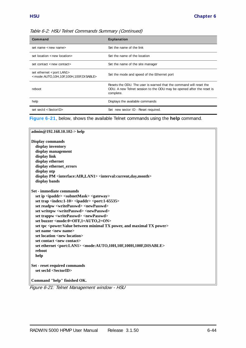
HSU Chapter 6
RADWIN 5000 HPMP User Manual Release 3.1.50 6-44
Figure 6-21, below, shows the available Telnet commands using the help command.
Figure 6-21: Telnet Management window - HSU
set name <new name> Set the name of the link
set location <new location> Set the name of the location
set contact <new contact> Set the name of the site manager
set ethernet <port:LAN1> <mode:AUTO,10H,10F,100H,100F,DISABLE>
Set the mode and speed of the Ethernet port
rebootResets the ODU. The user is warned that the command will reset the ODU. A new Telnet session to the ODU may be opened after the reset is complete.
help Displays the available commands
set secId <SectorID> Set new sector ID - Reset required.
[email protected]> help
Display commands display inventory display management display link display ethernet display ethernet_errors display ntp display PM <interface:AIR,LAN1> <interval:current,day,month> display bands
Set - immediate commands set ip <ipaddr> <subnetMask> <gateway> set trap <index:1-10> <ipaddr> <port:1-65535> set readpw <writePasswd> <newPasswd> set writepw <writePasswd> <newPasswd> set trappw <writePasswd> <newPasswd> set buzzer <mode:0=OFF,1=AUTO,2=ON> set tpc <power:Value between minimal TX power, and maximal TX power> set name <new name> set location <new location> set contact <new contact> set ethernet <port:LAN1> <mode:AUTO,10H,10F,100H,100F,DISABLE> reboot help
Set - reset required commands set secId <SectorID>
Command "help" finished OK.
Table 6-2: HSU Telnet Commands Summary (Continued)
Command Explanation

RADWIN 5000 HPMP User Manual Release 3.1.50 7-1
Chapter 7
Direct HSU ConfigurationScope of this Chapter
Direct management of a HSU may be carried out by a direct LAN connection to a managing computer (on-site) or over-the-air (from the HBS site).
There are several differences in the configuration functionality for a directly managed HSU compared to the method of Chapter 6 depending on whether the HSU is registered to a HBS, unregistered or not a member of any sector.
Where configuration function is identical under direct connection and through the HBS, we will not repeat the details, which may be seen in Chapter 6.
Configuring a HSU
Log on to the HSU either directly or over-the-air as shown in Chapter 4. You will see a dis-play like this:

Configuration Menu Buttons Chapter 7
RADWIN 5000 HPMP User Manual Release 3.1.50 7-2
Figure 7-1: Direct or over the air connection to a HSU
Configuration Menu Buttons
The Backup and Restore buttons have the same functionality as the corresponding buttons for the HBS. They provide for backup and restore of the HSU software.
The Buzzer button may set or mute the buzzer.
Recall that the buzzer tone is used for HSU antenna alignment.
The Refresh button restores the current window to its previous state abandoning any changes you made, provided that you did not click Apply or OK.
We will work through each of the Configuration tabs in turn:

System Chapter 7
RADWIN 5000 HPMP User Manual Release 3.1.50 7-3
System
Figure 7-2: HSU Configuration window (Direct)
These items are convenience fields. They are typically entered before the sector is brought up.
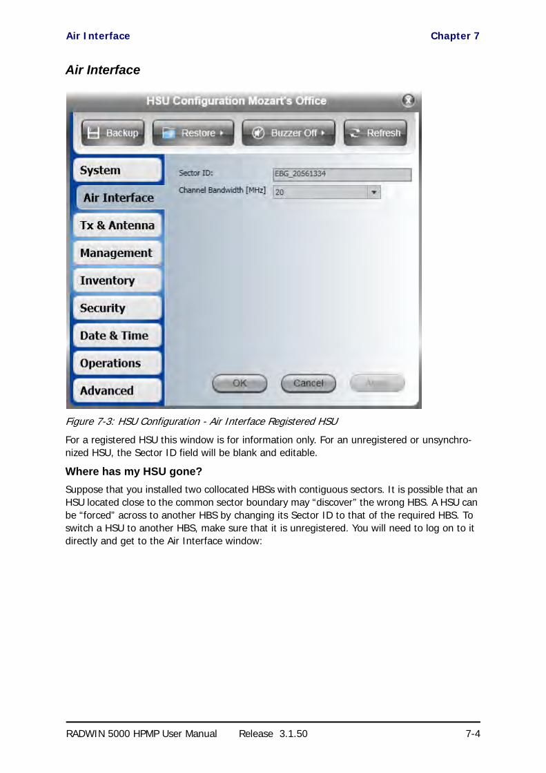
Air Interface Chapter 7
RADWIN 5000 HPMP User Manual Release 3.1.50 7-4
Air Interface
Figure 7-3: HSU Configuration - Air Interface Registered HSU
For a registered HSU this window is for information only. For an unregistered or unsynchro-nized HSU, the Sector ID field will be blank and editable.
Where has my HSU gone?
Suppose that you installed two collocated HBSs with contiguous sectors. It is possible that an HSU located close to the common sector boundary may “discover” the wrong HBS. A HSU can be “forced” across to another HBS by changing its Sector ID to that of the required HBS. To switch a HSU to another HBS, make sure that it is unregistered. You will need to log on to it directly and get to the Air Interface window:

Air Interface Chapter 7
RADWIN 5000 HPMP User Manual Release 3.1.50 7-5
Figure 7-4: HSU Configuration - Air Interface Unregistered HSU
Enter the Sector ID of the required HBS and click OK. The HSU should then “discover” the required HBS.

Tx & Antenna Chapter 7
RADWIN 5000 HPMP User Manual Release 3.1.50 7-6
Tx & Antenna
See page 6-22.
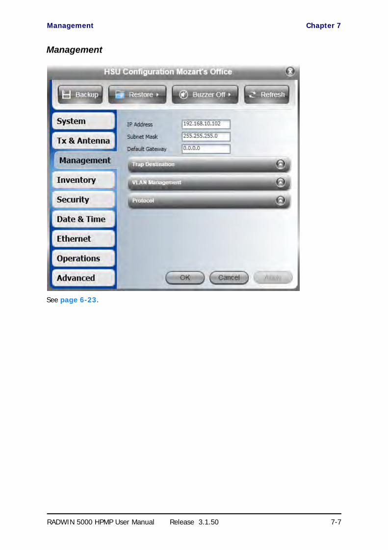
Management Chapter 7
RADWIN 5000 HPMP User Manual Release 3.1.50 7-7
Management
See page 6-23.

Inventory Chapter 7
RADWIN 5000 HPMP User Manual Release 3.1.50 7-8
Inventory
See page 6-24.

Security Chapter 7
RADWIN 5000 HPMP User Manual Release 3.1.50 7-9
Security
You may only change the SNMP community strings over a direct or over-the-air connection. You can change the Link Password for an un-synchronized HSU. Otherwise the functionality is the same as in page 6-25.

Date & Time Chapter 7
RADWIN 5000 HPMP User Manual Release 3.1.50 7-10
Date & Time
See page 6-26.

Operations Chapter 7
RADWIN 5000 HPMP User Manual Release 3.1.50 7-11
Operations
See page 6-29.
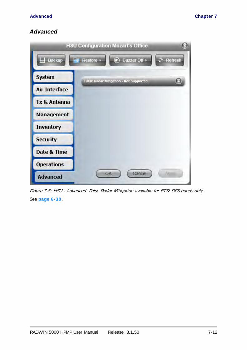
Advanced Chapter 7
RADWIN 5000 HPMP User Manual Release 3.1.50 7-12
Advanced
Figure 7-5: HSU - Advanced: False Radar Mitigation available for ETSI DFS bands only
See page 6-30.

RADWIN 5000 HPMP User Manual Release 3.1.50 8-1
Chapter 8
Monitoring andDiagnostics
The RADWIN Manager application enables you to monitor the sector, as well as perform basic diagnostic operations such as throughput testing.
This chapter covers:
• Retrieving link information
• Throughput checking• Recent events• Performance monitoring
• Active Alarms• Link Budget Calculator• Online Help
• Obtaining support
Retrieving Link Information (Get Diagnostics)
The Get Diagnostics feature collects and writes all link and Manager information (from both sites) into a text file. The file information can be used for diagnostics and should be sent to RADWIN Customer Support to speed up assistance.
The following table lists link and system information that can be monitored.
Table 8-1: Get Diagnostics Data and Description
Data Description
System Data General information about the system
Events Log• List of system events including those from other sites if this site is defined as the trap
destination• Last 256 events from all sites
Sector Information Information about the HBS and HSU settings
Site Configuration Data about the site parameters

Retrieving Link Information (Get Diagnostics) Chapter 8
RADWIN 5000 HPMP User Manual Release 3.1.50 8-2
To get diagnostics:
1. Click the Get Diagnostics button:
Figure 8-1: Get Diagnostics Dialog Box - HBS
Figure 8-2: Get Diagnostics Dialog Box - HSU
Monitor Detailed event data record
Performance Monitor Network performance data over defined time periods - - every 15 minutes for 30 days
Table 8-1: Get Diagnostics Data and Description (Continued)
Data Description

Throughput Checking Chapter 8
RADWIN 5000 HPMP User Manual Release 3.1.50 8-3
2. Select or deselect the data options. If the file is to be sent to RADWIN Customer Sup-port leave all options checked.
3. HBS only: Choose HSUs to be included.
4. Click File Path to specify the file name and older in which you want to save the file and then click Run to save the information.
On completion, the status of the checked items is confirmed:
The content of the Diagnostics report is an aggregate of all the more specific reports discussed below. It is largely self-explanatory.
Throughput Checking
In this mode, RADWIN 5000 HPMP estimates Ethernet throughput by filling frames over the air to maximum for 30 seconds. This mode should not influence service. The test may be car-ried out for the HBS or a HSU.
To use Throughput Checking:
1. HBS: Chose Estimated Throughput as shown:
HSU from HBS: Chose Estimated Throughput as shown:

Recent Events Chapter 8
RADWIN 5000 HPMP User Manual Release 3.1.50 8-4
HSU direct or over the air: Unavailable.
2. In either case, you are asked to enter the testing period:
3. Enter the required time and click OK to continue. The Ethernet services area changes appearance and the estimated throughput is displayed:
At the end of 30 seconds, the display reverts to normal.
Recent Events
The Recent Events log records system failures, loss of synchronization, loss of signal, compat-ibility problems and other fault conditions and events.
Note
The foregoing event types include events from all links for which this managing computer has been defined as the traps address. Only events from RADWIN equipment will be shown.

Recent Events Chapter 8
RADWIN 5000 HPMP User Manual Release 3.1.50 8-5
Alarms (traps) are displayed in the Events Log in the lower panel of the main window. The Events Log may be saved as a text file.
The Events Log includes the following fields:
» Sequential number (ID)
» Date and time stamp
» Message
» Trap source
» IP address of the ODU that initiated alarm.
You may filter the events shown by choosing All or Internal.
A full report may be seem by clicking Recent Events:

Recent Events Chapter 8
RADWIN 5000 HPMP User Manual Release 3.1.50 8-6
Figure 8-3: Recent Events: Left- HBS, Center HSU from HBS, Right HSU direct
In each case the report has the same format:
The left button may be used to save the report to a file.
mp
mmmmmmmmmp
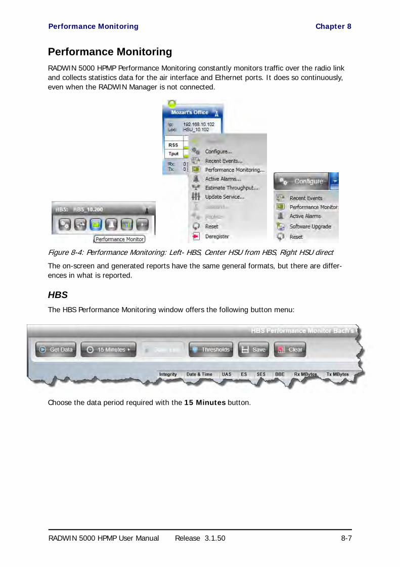
Performance Monitoring Chapter 8
RADWIN 5000 HPMP User Manual Release 3.1.50 8-7
Performance Monitoring
RADWIN 5000 HPMP Performance Monitoring constantly monitors traffic over the radio link and collects statistics data for the air interface and Ethernet ports. It does so continuously, even when the RADWIN Manager is not connected.
Figure 8-4: Performance Monitoring: Left- HBS, Center HSU from HBS, Right HSU direct
The on-screen and generated reports have the same general formats, but there are differ-ences in what is reported.
HBS
The HBS Performance Monitoring window offers the following button menu:
Choose the data period required with the 15 Minutes button.

HBS Chapter 8
RADWIN 5000 HPMP User Manual Release 3.1.50 8-8
• Current gives you the latest entry.• 15 Minutes provides data in a scroll down list in 15 minute intervals
• Daily (24 hours) shows results for the last 30 days at midnight.
The Threshold button enables you to set the upper traffic threshold for reporting. Traffic con-ditions above the threshold indicate congestion and probably lost frames.
Figure 8-5: Setting the upper traffic threshold
To get data for display, click Get Data. The process may take a few seconds.
Here is an extract Performance Monitoring report based on 15 minutes recording:
Figure 8-6: HBS - Performance Monitoring report - Valid data

HSU Chapter 8
RADWIN 5000 HPMP User Manual Release 3.1.50 8-9
The meaning of the column headings is shown in the following table:
Data becomes invalidated following a reset. In the example below, the HBS was reset shortly after 11:00. All data prior to that time becomes invalidated. The only valid item is the first recording after re-sync.
Figure 8-7: HBS - Performance Monitoring report - Showing invalid data
Use the Save button to store the current data to file and the Clear button to delete currently stored performance data.
HSU
The Performance Monitoring window for the HSU is slightly different depending on whether you access it from the HBS or directly:
Table 8-2: HBS Performance Monitoring Fields
Column Heading Abbreviation Meaning Description
Integrity Valid data flag
Green tick for current and valid; Red cross for invalidated data (See example below). Note that the Performance Monitoring data is not valid if not all the values were stored (e.g., due to clock changes within the interval or power up reset)
Date & Time Time stampData are recorded every 15 minutes; the last 30 days of recordings are maintained. Roll-over is at midnight.
UAS Unavailable Seconds Seconds in which the interface was out of service.
ES Errored seconds The number of seconds in which there was at least one error block.
SESSevere Errored Seconds
The number of seconds in which the service quality was low as determined by the BBER threshold.
BBEBackground Block Error
The number of errored blocks in an interval.
Rx MBytes Received Mbytes The number of Megabytes received at the specified port within the interval
Tx MBytes Transmitted MbytesThe number of Megabytes transmitted at the specified port within the interval.
Above Traffic ThreshThreshold set in Figure 8-5 Seconds count when actual traffic exceeded the threshold
Active Seconds The number of seconds that the configured Ethernet service is active

HSU Chapter 8
RADWIN 5000 HPMP User Manual Release 3.1.50 8-10
From the HBS
You may chose between an uplink or downlink report. The remaining buttons have the same functionality as they do for the HBS. (There is no significance in monitoring period button label, Daily. The options are as for the HBS.)
Direct or Over the Air
Here, only a downlink report is available. Otherwise the buttons have the same functionality as they do for the HBS.
Here is an extract from a 15 minute report. We have broken it into three pieces so that it is legible:
Figure 8-8: HSU - Performance Monitoring report - Both valid and invalid data (1 of 3)

HSU Chapter 8
RADWIN 5000 HPMP User Manual Release 3.1.50 8-11
Figure 8-9: HSU - Performance Monitoring report - Both valid and invalid data (2 of 3)
Figure 8-10: HSU - Performance Monitoring report - Both valid and invalid data (3 of 3)
The HSU report contains many more fields than the HBS. Here is their meaning::
Table 8-3: HSU Performance Monitoring Fields
Column Heading Abbreviation Meaning Description
Integrity Valid data flag
Green tick for current and valid; Red cross for invalidated data (See example below). Note that the Performance Monitoring data is not valid if not all the values were stored (e.g., due to clock changes within the interval or power up reset)
Date & Time Time stampData are recorded every 15 minutes; the last 30 days of recordings are maintained. Roll-over is at midnight
UAS Unavailable Seconds Seconds in which the interface was out of service
ES Errored seconds The number of seconds in which there was at least one error block.
SESSevere Errored Seconds
The number of seconds in which the service quality was low as determined by the BBER threshold
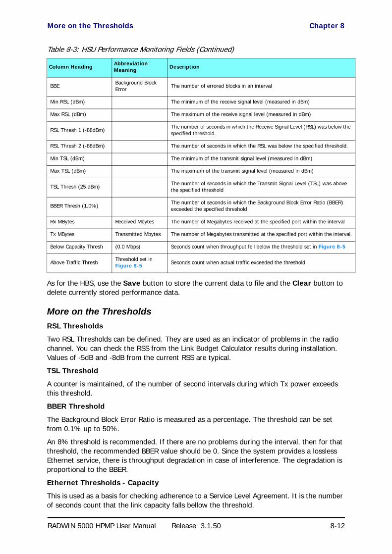
More on the Thresholds Chapter 8
RADWIN 5000 HPMP User Manual Release 3.1.50 8-12
As for the HBS, use the Save button to store the current data to file and the Clear button to delete currently stored performance data.
More on the Thresholds
RSL Thresholds
Two RSL Thresholds can be defined. They are used as an indicator of problems in the radio channel. You can check the RSS from the Link Budget Calculator results during installation. Values of -5dB and -8dB from the current RSS are typical.
TSL Threshold
A counter is maintained, of the number of second intervals during which Tx power exceeds this threshold.
BBER Threshold
The Background Block Error Ratio is measured as a percentage. The threshold can be set from 0.1% up to 50%.
An 8% threshold is recommended. If there are no problems during the interval, then for that threshold, the recommended BBER value should be 0. Since the system provides a lossless Ethernet service, there is throughput degradation in case of interference. The degradation is proportional to the BBER.
Ethernet Thresholds - Capacity
This is used as a basis for checking adherence to a Service Level Agreement. It is the number of seconds count that the link capacity falls bellow the threshold.
BBEBackground Block Error
The number of errored blocks in an interval
Min RSL (dBm) The minimum of the receive signal level (measured in dBm)
Max RSL (dBm) The maximum of the receive signal level (measured in dBm)
RSL Thresh 1 (-88dBm)The number of seconds in which the Receive Signal Level (RSL) was below the specified threshold.
RSL Thresh 2 (-88dBm) The number of seconds in which the RSL was below the specified threshold.
Min TSL (dBm) The minimum of the transmit signal level (measured in dBm)
Max TSL (dBm) The maximum of the transmit signal level (measured in dBm)
TSL Thresh (25 dBm)The number of seconds in which the Transmit Signal Level (TSL) was above the specified threshold
BBER Thresh (1.0%)The number of seconds in which the Background Block Error Ratio (BBER) exceeded the specified threshold
Rx MBytes Received Mbytes The number of Megabytes received at the specified port within the interval
Tx MBytes Transmitted Mbytes The number of Megabytes transmitted at the specified port within the interval.
Below Capacity Thresh (0.0 Mbps) Seconds count when throughput fell below the threshold set in Figure 8-5
Above Traffic ThreshThreshold set in Figure 8-5 Seconds count when actual traffic exceeded the threshold
Table 8-3: HSU Performance Monitoring Fields (Continued)
Column Heading Abbreviation Meaning Description
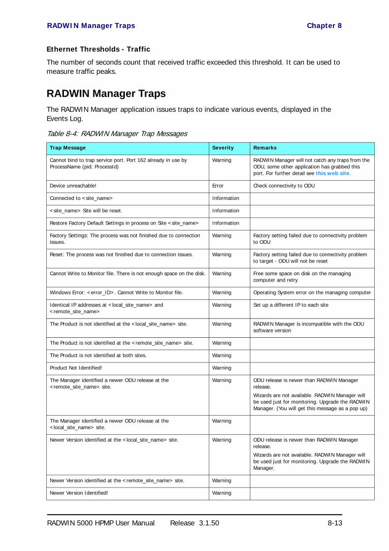
RADWIN Manager Traps Chapter 8
RADWIN 5000 HPMP User Manual Release 3.1.50 8-13
Ethernet Thresholds - Traffic
The number of seconds count that received traffic exceeded this threshold. It can be used to measure traffic peaks.
RADWIN Manager Traps
The RADWIN Manager application issues traps to indicate various events, displayed in the Events Log.
Table 8-4: RADWIN Manager Trap Messages
Trap Message Severity Remarks
Cannot bind to trap service port. Port 162 already in use by ProcessName (pid: ProcessId)
Warning RADWIN Manager will not catch any traps from the ODU, some other application has grabbed this port. For further detail see this web site.
Device unreachable! Error Check connectivity to ODU
Connected to <site_name> Information
<site_name> Site will be reset. Information
Restore Factory Default Settings in process on Site <site_name> Information
Factory Settings: The process was not finished due to connection issues.
Warning Factory setting failed due to connectivity problem to ODU
Reset: The process was not finished due to connection issues. Warning Factory setting failed due to connectivity problem to target - ODU will not be reset
Cannot Write to Monitor file. There is not enough space on the disk. Warning Free some space on disk on the managing computer and retry
Windows Error: <error_ID>. Cannot Write to Monitor file. Warning Operating System error on the managing computer
Identical IP addresses at <local_site_name> and <remote_site_name>
Warning Set up a different IP to each site
The Product is not identified at the <local_site_name> site. Warning RADWIN Manager is incompatible with the ODU software version
The Product is not identified at the <remote_site_name> site. Warning
The Product is not identified at both sites. Warning
Product Not Identified! Warning
The Manager identified a newer ODU release at the <remote_site_name> site.
Warning ODU release is newer than RADWIN Manager release.
Wizards are not available. RADWIN Manager will be used just for monitoring. Upgrade the RADWIN Manager. (You will get this message as a pop up)
The Manager identified a newer ODU release at the <local_site_name> site.
Warning
Newer Version identified at the <local_site_name> site. Warning ODU release is newer than RADWIN Manager release.
Wizards are not available. RADWIN Manager will be used just for monitoring. Upgrade the RADWIN Manager.
Newer Version identified at the <remote_site_name> site. Warning
Newer Version Identified! Warning

Active Alarms Chapter 8
RADWIN 5000 HPMP User Manual Release 3.1.50 8-14
Active Alarms
Active Alarms are raised for any event affecting availability or quality of service.
The Active Alarms button, is available for the HBS and the HSUs.Her is an example:
Current Active Alarms may be saved to a file. The list displayed will not be updated unless you click Refresh.
Other Diagnostic Aids
Link Budget Calculator
The Link Budget Calculator is part of the RADWIN Manager software and is found in the Help menu. This useful utility enables you to calculate the expected performance of the wireless link and the possible configurations for a specific link range including antenna size, cable loss and climate conditions. For full details, see Chapter 16.
To run the Link Budget Calculator from the Windows Start Menu:
• Go to Start | Programs | RADWIN Manager | Link Budget Calculator
Online Help
Online help can be accessed from the Help menu on the main window of the RADWIN Man-ager. Using most common Web browsers, it may also be run going to
Start | Programs | RADWIN Manager | User Manual RADWIN 5000 HPMP
Customer Support
Customer support for this product can be obtained from the local VAR, Integrator or distribu-tor from whom it was purchased.
For further information, please contact the RADWIN distributor nearest to you or one of RAD-WIN's offices worldwide (see the RADWIN Worldwide Offices at the beginning of this manual).
RADWIN 5000 HPMP
Point to Multipoint Broadband Wireless
USER MANUAL
RELEASE 3.1.50
Part 4: Site Synchronization
UM 5000-3150/06.11

RADWIN 5000 HPMP User Manual Release 3.1.50 9-1
Chapter 9
Hub Site SynchronizationScope of this Chapter
This chapter is specific to collocating HBSs. Should you require to collocate with other radio models, you should consult with RADWIN Customer Service.
What is Hub Site Synchronization?
When several units are collocated at a common hub site, interference may occur from one unit to another. RADWIN ODU units support the collocation of more than two units at a cen-tral site. Like any other RF deployment, the wireless operation is highly dependent on factors such as available frequencies, the physical spacing between radios, other interfering radios, and whether WinLink 1000, RADWIN 2000 or RADWIN 5000 HPMP units are installed.
The RADWIN Hub Site Synchronization (HSS) method uses a cable connected from the mas-ter ODU to all collocated ODUs; this cable carries pulses sent to each ODU, which synchronize their transmission with each other. The pulse synchronization ensures that transmission occurs at the same time for all collocated units. This also results in all of the hub site units receiving data at the same time, eliminating the possibility of interference that could result if some units transmit while other units at the same location receive.
Figure 9-1 illustrates interference caused by non-synchronized collocated units.
Note
HSS does not eliminate the need for careful RF planning to ensure the design will work as planned. See Chapter 2 for information on installation site survey.

What is Hub Site Synchronization? Chapter 9
RADWIN 5000 HPMP User Manual Release 3.1.50 9-2
Figure 9-1: Interference caused by collocated units
Adding HSS removes interference as shown in the next two figures:
Figure 9-2: Collocated units using Hub Site Synchronization (1)
Figure 9-3: Collocated units using Hub Site Synchronization (2)
The units are connected to each other with HSS cables and HSS Distribution Units.
One of the radios in the site is defined as HSS Master and generates synchronization pulses.
The other collocated radios in the site - the HSS Clients, are connected to the HSS Master and synchronize their transmission to the pulses. An HSS Client can be configured to work in one of two modes:
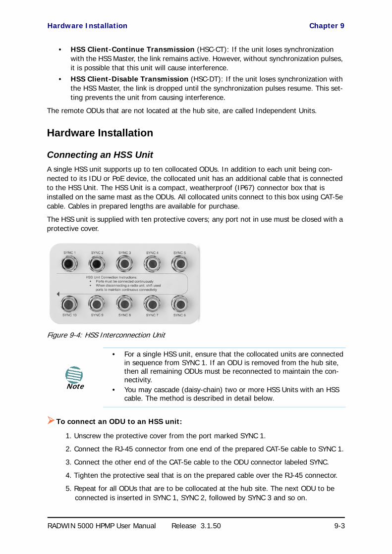
Hardware Installation Chapter 9
RADWIN 5000 HPMP User Manual Release 3.1.50 9-3
• HSS Client-Continue Transmission (HSC-CT): If the unit loses synchronization with the HSS Master, the link remains active. However, without synchronization pulses, it is possible that this unit will cause interference.
• HSS Client-Disable Transmission (HSC-DT): If the unit loses synchronization with the HSS Master, the link is dropped until the synchronization pulses resume. This set-ting prevents the unit from causing interference.
The remote ODUs that are not located at the hub site, are called Independent Units.
Hardware Installation
Connecting an HSS Unit
A single HSS unit supports up to ten collocated ODUs. In addition to each unit being con-nected to its IDU or PoE device, the collocated unit has an additional cable that is connected to the HSS Unit. The HSS Unit is a compact, weatherproof (IP67) connector box that is installed on the same mast as the ODUs. All collocated units connect to this box using CAT-5e cable. Cables in prepared lengths are available for purchase.
The HSS unit is supplied with ten protective covers; any port not in use must be closed with a protective cover.
Figure 9-4: HSS Interconnection Unit
To connect an ODU to an HSS unit:
1. Unscrew the protective cover from the port marked SYNC 1.
2. Connect the RJ-45 connector from one end of the prepared CAT-5e cable to SYNC 1.
3. Connect the other end of the CAT-5e cable to the ODU connector labeled SYNC.
4. Tighten the protective seal that is on the prepared cable over the RJ-45 connector.
5. Repeat for all ODUs that are to be collocated at the hub site. The next ODU to be connected is inserted in SYNC 1, SYNC 2, followed by SYNC 3 and so on.
Note
• For a single HSS unit, ensure that the collocated units are connected in sequence from SYNC 1. If an ODU is removed from the hub site, then all remaining ODUs must be reconnected to maintain the con-nectivity.
• You may cascade (daisy-chain) two or more HSS Units with an HSS cable. The method is described in detail below.

Using a Single HSS Unit Chapter 9
RADWIN 5000 HPMP User Manual Release 3.1.50 9-4
Using a Single HSS Unit
Figure 9-5: HSS Wiring schematic
The wiring, as shown in Figure 9-5 is self explanatory. The Sync signal path is less self-evi-dent. If we set ODU 1 (on SYNC 1) to HSS Master, then the Sync signal path is as shown in Figure 9-6. The signal travels from ODU 1 to SYNC 1, from SYNC 1 to SYNC 2, from SYNC 2 to ODU 2 and back again. The back and forth paths repeat for the second to fourth ODU, from left to right. The signal exits the HSS unit at SYNC 5 and terminates in ODU 5.
The choice of the ODU on SYNC 1 as HSS master is not mandatory, but is good practice. If for example we were to use ODU 3 as HSS master, the Sync signal path would be ODU 3 to SYNC 3, then left and right to SYNC 2 and SYNC 4. It would then propagate to ODUs 2 and 4, termi-nating at both ODUs 1 and 5.
Figure 9-6: HSS sync signal path with ODU 1 as HSS Master
Using More than One HSS Unit
In a large collocation site, several HSS units may be cascaded (daisy-chained) subject to the following conditions:
Condition 1: Cabling Sequence
1. Up to nine ODUs may be connected to the first HSS unit using HSS ports SYNC 1, SYNC 2, SYNC 3,... up to SYNC 9 in order without leaving empty ports.
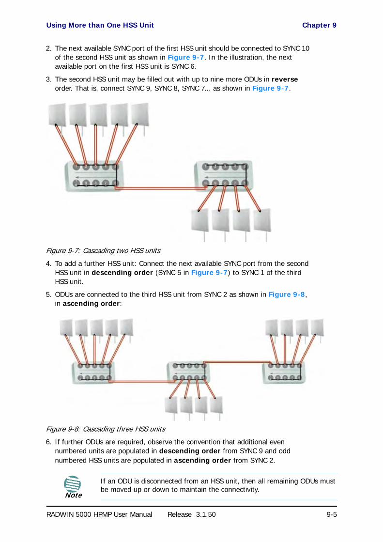
Using More than One HSS Unit Chapter 9
RADWIN 5000 HPMP User Manual Release 3.1.50 9-5
2. The next available SYNC port of the first HSS unit should be connected to SYNC 10 of the second HSS unit as shown in Figure 9-7. In the illustration, the next available port on the first HSS unit is SYNC 6.
3. The second HSS unit may be filled out with up to nine more ODUs in reverse order. That is, connect SYNC 9, SYNC 8, SYNC 7... as shown in Figure 9-7.
Figure 9-7: Cascading two HSS units
4. To add a further HSS unit: Connect the next available SYNC port from the second HSS unit in descending order (SYNC 5 in Figure 9-7) to SYNC 1 of the third HSS unit.
5. ODUs are connected to the third HSS unit from SYNC 2 as shown in Figure 9-8, in ascending order:
Figure 9-8: Cascading three HSS units
6. If further ODUs are required, observe the convention that additional even numbered units are populated in descending order from SYNC 9 and odd numbered HSS units are populated in ascending order from SYNC 2.
Note
If an ODU is disconnected from an HSS unit, then all remaining ODUs must be moved up or down to maintain the connectivity.

ODU/HSS Unit Connection Pinout Chapter 9
RADWIN 5000 HPMP User Manual Release 3.1.50 9-6
Condition 2: Total HSS Cable Length
The total path of the HSS sync pulse must not exceed 300m. This applies no matter how many HSS units are used. To illustrate the method for calculating the sync pulse path length we show three examples. For our purpose, let:
Lmn denote the length of the ODU-HSS unit cable at SYNC n on HSS unit m
Hm be the length of the cable joining HSS unit m to HSS unit m+1
One HSS unit with five collocated ODUs
Two cascaded HSS units as shown in Figure 9-7
Three cascaded HSS units as shown in Figure 9-8
ODU/HSS Unit Connection Pinout
Radio Frame Pattern (RFP)
A Radio Frame Pattern (RFP) is the cycle duration of transmit and receive of the air-frame.
Table 9-1: ODU/HSS Unit Connection Pinout
Color ODU RJ-45
HSS UNIT RJ-45
White/Green 1 1
GreenNot connected
White/Orange
Orange 6 6
Blue 4 4
White/Blue 5 5
White/Brown 7 7
Brown 8 8
PathLength L11 2 L12 2 L13+ 2 L14 L15++ +=
PathLength L11 2 L12 2 L13 2 L14+2
+L15
+H1 2 L29 2+ L28 2+ L27 L26+
++ +
=
PathLength L11 2 L12 2 L13 2 L14+2
+L15
+H1 2 L29 2+ L28 2+ L27 2 L 26+
H2 2 L32 2 L33 2 L34 L35+++
++ + +
+
=
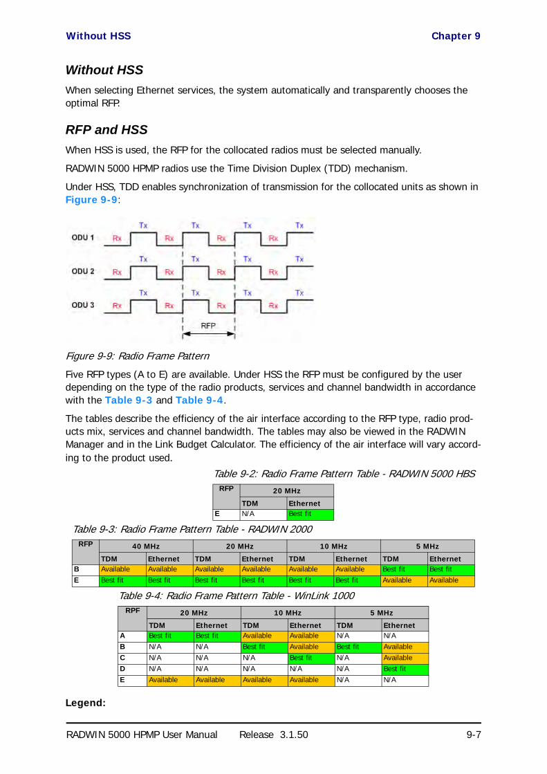
Without HSS Chapter 9
RADWIN 5000 HPMP User Manual Release 3.1.50 9-7
Without HSS
When selecting Ethernet services, the system automatically and transparently chooses the optimal RFP.
RFP and HSS
When HSS is used, the RFP for the collocated radios must be selected manually.
RADWIN 5000 HPMP radios use the Time Division Duplex (TDD) mechanism.
Under HSS, TDD enables synchronization of transmission for the collocated units as shown in Figure 9-9:
Figure 9-9: Radio Frame Pattern
Five RFP types (A to E) are available. Under HSS the RFP must be configured by the user depending on the type of the radio products, services and channel bandwidth in accordance with the Table 9-3 and Table 9-4.
The tables describe the efficiency of the air interface according to the RFP type, radio prod-ucts mix, services and channel bandwidth. The tables may also be viewed in the RADWIN Manager and in the Link Budget Calculator. The efficiency of the air interface will vary accord-ing to the product used.
Legend:
Table 9-2: Radio Frame Pattern Table - RADWIN 5000 HBSRFP 20 MHz
TDM EthernetE N/A Best fit
Table 9-3: Radio Frame Pattern Table - RADWIN 2000RFP 40 MHz 20 MHz 10 MHz 5 MHz
TDM Ethernet TDM Ethernet TDM Ethernet TDM EthernetB Available Available Available Available Available Available Best fit Best fitE Best fit Best fit Best fit Best fit Best fit Best fit Available Available
Table 9-4: Radio Frame Pattern Table - WinLink 1000RPF 20 MHz 10 MHz 5 MHz
TDM Ethernet TDM Ethernet TDM EthernetA Best fit Best fit Available Available N/A N/AB N/A N/A Best fit Available Best fit AvailableC N/A N/A N/A Best fit N/A AvailableD N/A N/A N/A N/A N/A Best fitE Available Available Available Available N/A N/A

RFP: General Radio Frame Pattern Chapter 9
RADWIN 5000 HPMP User Manual Release 3.1.50 9-8
Best fit - optimal RFP choice for TDM and Ethernet services.
Available - available RFP for TDM and Ethernet services, but not optimal.
N/A - service unavailable
Select the RFP that gives you the Best Fit or Available for required system services and select the channel bandwidth accordingly.
RFP: General Radio Frame Pattern
When setting the RPF, the following considerations should be borne in mind:
• When synchronizing RADWIN 5000 HBS units you must use RFP E• When synchronizing RADWIN 5000 HBS with RADWIN 2000 or WinLink 1000 units
you must use RFP E• RFP influences capacity and latency.• Using the Link Budget Calculator, you can see the effect of the RFP on the Ethernet
throughput.
Sector Configuration and HSS
The Hub Site Synchronization Settings dialog box appears in both the HBS Site Configuration window.
NoteThe RFP must be the same for each link within the collocated system.

Sector Configuration and HSS Chapter 9
RADWIN 5000 HPMP User Manual Release 3.1.50 9-9
Figure 9-10: HSS Settings window
If you click the Enabled box, the central display (with Operational state opened) will look like this:

Sector Configuration and HSS Chapter 9
RADWIN 5000 HPMP User Manual Release 3.1.50 9-10
Figure 9-11: Setting HBS as HSM or HSC
Continue Tx means that the HBS as a client to continue to work if there is no HSM pulse.
If you select Hub Sync Master and click Apply, the display changes again:
Figure 9-12: HBS as HSM
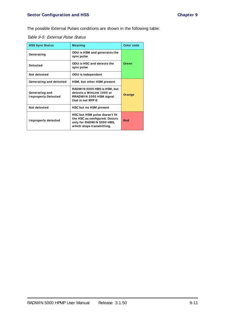
Sector Configuration and HSS Chapter 9
RADWIN 5000 HPMP User Manual Release 3.1.50 9-11
The possible External Pulses conditions are shown in the following table:
Table 9-5: External Pulse Status
HSS Sync Status Meaning Color code
Generating ODU is HSM and generates the sync pulse
GreenDetected ODU is HSC and detects the sync pulse
Not detected ODU is independent
Generating and detected HSM, but other HSM present
OrangeGenerating and Improperly Detected
RADWIN 5000 HBS is HSM, but detects a WinLink 1000 or RRADWIN 2000 HSM signal that is not RFP E
Not detected HSC but no HSM present
Improperly detected
HSC but HSM pulse doesn’t fit the HSC as configured. Occurs only for RADWIN 5000 HBS, which stops transmitting.
Red

RADWIN 5000 HPMP User Manual Release 3.1.50 10-1
Chapter 10
Using the RADWIN GSUWhat is it for
The GPS-based synchronization unit (GSU) is designed to handle inter-site interferences under large-scale deployment scenarios.
The GSU is an outdoor unit consisting of a standard WinLink 1000 enclosure, a GPS antenna and a PoE device.
The GSU is connected to the HSS Unit using a standard HSS cable. It synchronizes the trans-mission timing of multiple Hub-Sites to the same clock source thus eliminating self interfer-ence.
GSU Functionality
The GSU receives a synchronization signal from the GPS once per second. It distributes a RADWIN proprietary synchronization signal to all other ODU units using the RS422 protocol and the standard HSS mechanism, where the GSU acts as an HSM unit.
When the GSU doesn’t receive a synchronization signal from the GPS for 30 seconds, it moves automatically to Self-Generation mode and acts as a regular HSM unit, until the GPS recovers.
Typical GSU Scenarios
Independent Distributed Sites
In the scenario of Figure 10-1, we have multiple independent collocated sites, which may interfere with each other. To meet this situation, we coordinate all of them using the GSU as shown.
The GSU functions like “wide area HSS unit”, ensuring that all participating radios at the loca-tions marked GSU each transmit and receive at the same time.

Multiple Distributed Sites with Communication Chapter 10
RADWIN 5000 HPMP User Manual Release 3.1.50 10-2
ted sit
Figure 10-1: GSU Scenario - Independent distributed sites
Multiple Distributed Sites with Communication
What happens if, in Figure 10-1, the GSU towers themselves have radios communicating as shown in Figure 10-2?
Consider GSU 1 and GSU 2: Both collocated towers transmit and receive simultaneously. How-ever, the radios communicating at GSU 1 and GSU 2 must transmit and receive in turn accord-ing to the scheme in marked “Normal Phase” in Figure 10-3. This is an impossible situation, if all the links must send and receive together. It is further complicated by adding a third and further sites as shown.
Figure 10-2: GSU Scenario - Communicating distributed sites
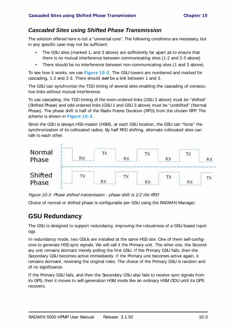
Cascaded Sites using Shifted Phase Transmission Chapter 10
RADWIN 5000 HPMP User Manual Release 3.1.50 10-3
Cascaded Sites using Shifted Phase Transmission
The solution offered here is not a “universal cure”. The following conditions are necessary, but in any specific case may not be sufficient:
• The GSU sites (marked 1, and 3 above) are sufficiently far apart as to ensure that there is no mutual interference between communicating sites (1-2 and 2-3 above)
• There should be no interference between non-communicating sites (1 and 3 above).
To see how it works, we use Figure 10-2. The GSU towers are numbered and marked for cascading, 1-2 and 2-3. There should not be a link between 1 and 3.
The GSU can synchronize the TDD timing of several sites enabling the cascading of consecu-tive links without mutual interference.
To use cascading, the TDD timing of the even-ordered links (GSU 2 above) must be “shifted” (Shifted Phase) and odd-ordered links (GSU 1 and GSU 3 above) must be “unshifted” (Normal Phase). The phase shift is half of the Radio Frame Duration (RFD) from the chosen RFP. The scheme is shown in Figure 10-3.
Since the GSU is always HSS master (HSM), at each GSU location, the GSU can “force” the synchronization of its collocated radios. By half RFD shifting, alternate collocated sites can talk to each other.
Figure 10-3: Phase shifted transmission - phase shift is 1/2 the RFD
Choice of normal or shifted phase is configurable per GSU using the RADWIN Manager.
GSU Redundancy
The GSU is designed to support redundancy, improving the robustness of a GSU based topol-ogy.
In redundancy mode, two GSUs are installed at the same HSS site. One of them self-config-ures to generate HSS sync signals. We will call it the Primary unit. The other one, the Second-ary unit remains dormant merely polling the first GSU. If the Primary GSU fails, then the Secondary GSU becomes active immediately. If the Primary unit becomes active again, it remains dormant, reversing the original roles. The choice of the Primary GSU is random and of no significance.
If the Primary GSU fails, and then the Secondary GSU also fails to receive sync signals from its GPS, then it moves to self-generation HSM mode like an ordinary HSM ODU until its GPS recovers.
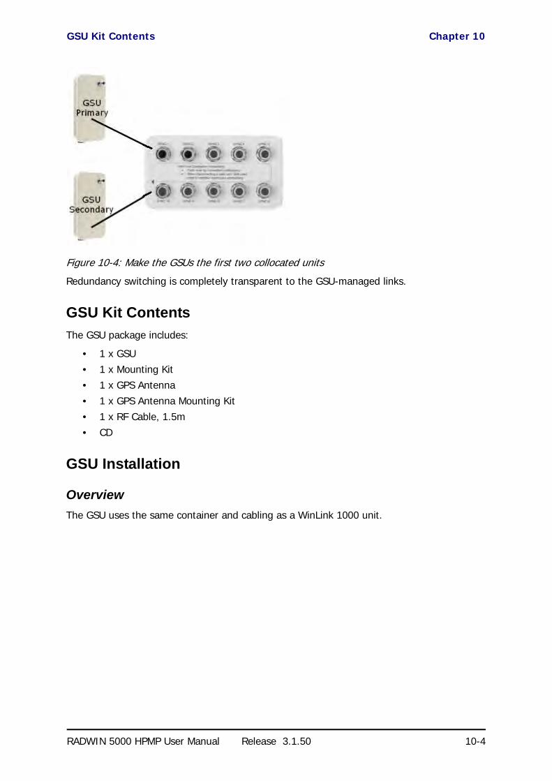
GSU Kit Contents Chapter 10
RADWIN 5000 HPMP User Manual Release 3.1.50 10-4
Figure 10-4: Make the GSUs the first two collocated units
Redundancy switching is completely transparent to the GSU-managed links.
GSU Kit Contents
The GSU package includes:
• 1 x GSU• 1 x Mounting Kit• 1 x GPS Antenna
• 1 x GPS Antenna Mounting Kit• 1 x RF Cable, 1.5m• CD
GSU Installation
Overview
The GSU uses the same container and cabling as a WinLink 1000 unit.

Preparing the GSU for Use Chapter 10
RADWIN 5000 HPMP User Manual Release 3.1.50 10-5
Figure 10-5: General GSU configuration
In that respect, all of the considerations of Chapter 3, Chapter 17 and Chapter 18 of the use Manual apply to the GSU.
It may be configured using the regular RADWIN Manager or Telnet.
Preparing the GSU for Use
Use the method of Chapter 19, Preloading an ODU with an IP Address to change the IP address from the default (10.0.0.120). In the example screen captures below, we use 192.168.222.20 with Subnet Mask 255.255.252.0.
Mounting the GSU
Mount the GSU and antenna. Ensure that its ODU port connected to its PoE device and the HSS cable is connected to the HSS unit as shown. The external LAN port of the PoE device is connected to the managing computer. If you are accessing the GSU through a network it is essential that you use the IP preloading method. The default IP address may be inaccessible and you may not use the Local Connection method over a network.
Configuring the GSUGetting Started
To configure the GSU, you log on to it, exactly as in Chapter 4.
The GSU Main Window
Here is the main window for GSU configuration:

Configuring the GSU Chapter 10
RADWIN 5000 HPMP User Manual Release 3.1.50 10-6
Figure 10-6: GSU Main widow at startup
The top five items in the GSU Monitor panel are taken from a satellite. The transmission Phase may be Normal as shown or Shifted. It purpose, together with the Tx Ratio bar, will be explained below.
The Status Box
Under normal operating conditions, it will be green as shown, indicating that it is synchro-nized with a satellite.
If satellite synchronization is lost, then the GSU will function as an independent HSM and the status box will change color:
The Main Menu
The main menu is a subset of the main menu applicable to the WinLink 1000. Notice that there are no Installation or Configuration wizards. Such configuration as is necessary is car-ried out using a modified version of Site Configuration for WinLink 1000.
Similarly, the Tool bar is a subset of that applicable to the WinLink 1000.

Configuring the GSU Chapter 10
RADWIN 5000 HPMP User Manual Release 3.1.50 10-7
Using Site Configuration for the GSUSite Configuration: System
Here is the opening window for Site Configuration:
Figure 10-7: Site Configuration: System
It is similar to that of the WinLink 1000.

Configuring the GSU Chapter 10
RADWIN 5000 HPMP User Manual Release 3.1.50 10-8
Site Configuration: GPS Sync Unit
This window is the main GSU configuration tool:
Figure 10-8: Site Configuration: GPS Sync Unit
1. Setting the RFP for HSS
The GSU is automatically configured as HSS Master (HSM).
If the hub site consists only of WinLink 1000 units, then any suitable RFP may be chosen. If there are one or more RADWIN 2000 units, you must use RFP B or E. If there are one or more RADWIN 5000 HBS units, you must use RFP E.
Note
Recall that RADWIN 5000 HBS can only use RFP E. In what follows below, references to RADWIN 2000 also apply to RADWIN 5000 HBS unless otherwise specified.
NoteEnsure that no other collocated ODU is configured as HSM.

Configuring the GSU Chapter 10
RADWIN 5000 HPMP User Manual Release 3.1.50 10-9
The permitted RFPs are also dependent on channel bandwidth and are color coded as fol-lows:
There is a further restriction: If there are two distributed sites transmitting to each other, they must both use the same RFP. This requirement, together with use of shifted transmis-sion phase (item 3 below), ensures that communicating distributed sites to not interfere with each other by transmitting simultaneously.
Two GSU managed sites transmitting with shifted transmission phase and using the same RFP, transmit one half a RFD apart (see Figure 10-3 above).
2. Setting the Tx Transmission Ratio
Since the GSU is always HSM, it must be able to cater for hub site RADWIN 2000 C based links. (See the RADWIN 2000 User Manual, Chapter 5). If you use asymmetric allocation, shifted transmission phase becomes unavailable and you cannot “cascade” links as described in step 1.
3. Choosing the Transmission Phase
Chose the Transmission Phase in accordance with considerations in step 1 above. If you choose Shifted Phase then the Asymmetric Ratio selector is disabled.
You May use RFP/Channel Bandwidth combinations with this color
For these collocated radios
WinLink 1000 only
RADWIN 2000 only
WinLink 1000 and RADWIN 2000 together
None - unavailable

Configuring the GSU Chapter 10
RADWIN 5000 HPMP User Manual Release 3.1.50 10-10
Site Configuration: Management
Figure 10-9: Site Configuration: Management
Here you set the GSU IP address, Subnet mask and gateway. You also set trap addresses here. It is identical to the corresponding panel for WinLink 1000.
mmp

Configuring the GSU Chapter 10
RADWIN 5000 HPMP User Manual Release 3.1.50 10-11
Site Configuration: Inventory
Figure 10-10: Site Configuration: Inventory
Site Configuration: Security
You can only change the SNMP Community stings:

Configuring the GSU Chapter 10
RADWIN 5000 HPMP User Manual Release 3.1.50 10-12
Figure 10-11: Site Configuration: Security
Site Configuration: Date and Time
ODU Recent events, alarms and traps are time-stamped from the time method chosen here (NTP, managing computer, ODU default).

Configuring the GSU Chapter 10
RADWIN 5000 HPMP User Manual Release 3.1.50 10-13
Figure 10-12: Setting the date and time for trap reporting
Site Configuration: Operations
The only available action here is Restore System Defaults:

Configuring the GSU Chapter 10
RADWIN 5000 HPMP User Manual Release 3.1.50 10-14
Figure 10-13: Site Configuration: Operations
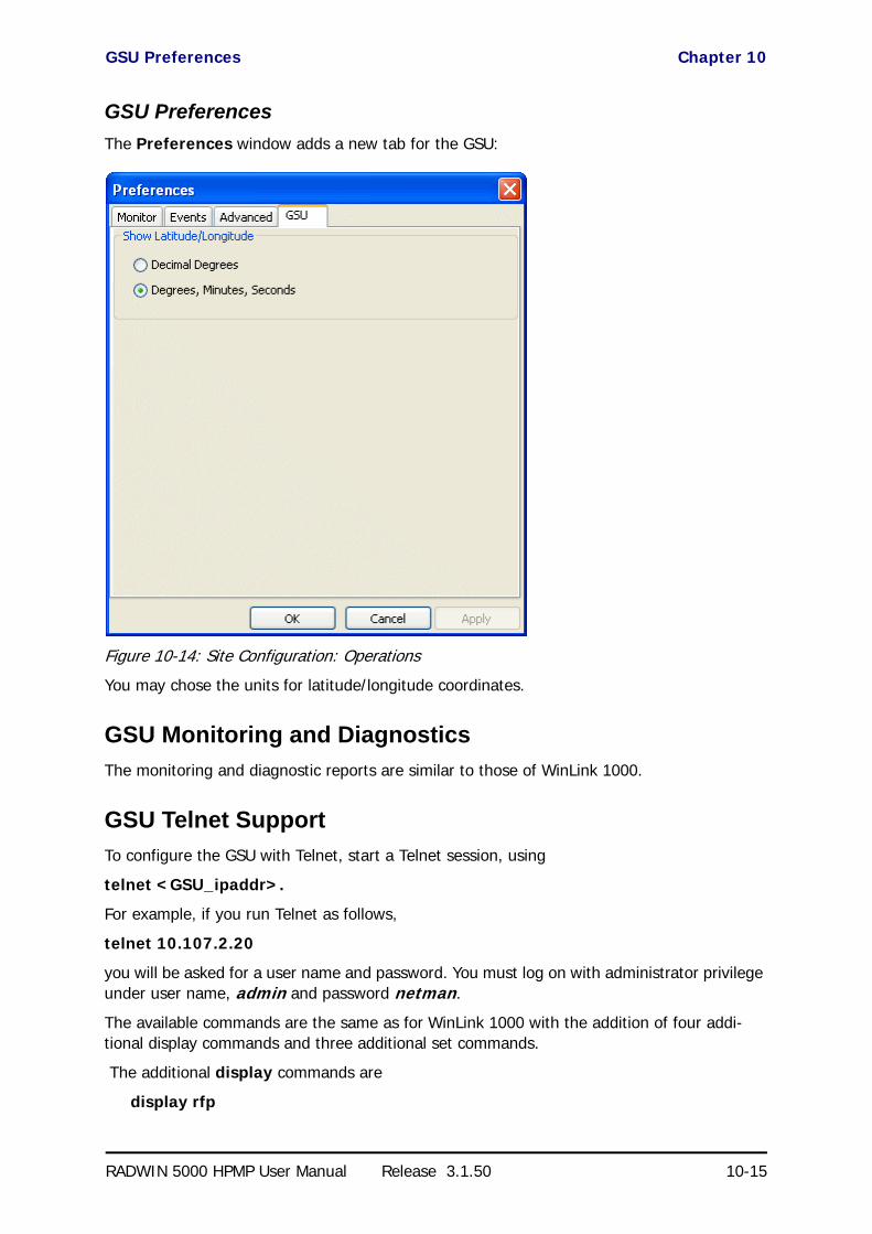
GSU Preferences Chapter 10
RADWIN 5000 HPMP User Manual Release 3.1.50 10-15
GSU Preferences
The Preferences window adds a new tab for the GSU:
Figure 10-14: Site Configuration: Operations
You may chose the units for latitude/longitude coordinates.
GSU Monitoring and Diagnostics
The monitoring and diagnostic reports are similar to those of WinLink 1000.
GSU Telnet Support
To configure the GSU with Telnet, start a Telnet session, using
telnet <GSU_ipaddr>.
For example, if you run Telnet as follows,
telnet 10.107.2.20
you will be asked for a user name and password. You must log on with administrator privilege under user name, admin and password netman.
The available commands are the same as for WinLink 1000 with the addition of four addi-tional display commands and three additional set commands.
The additional display commands are
display rfp
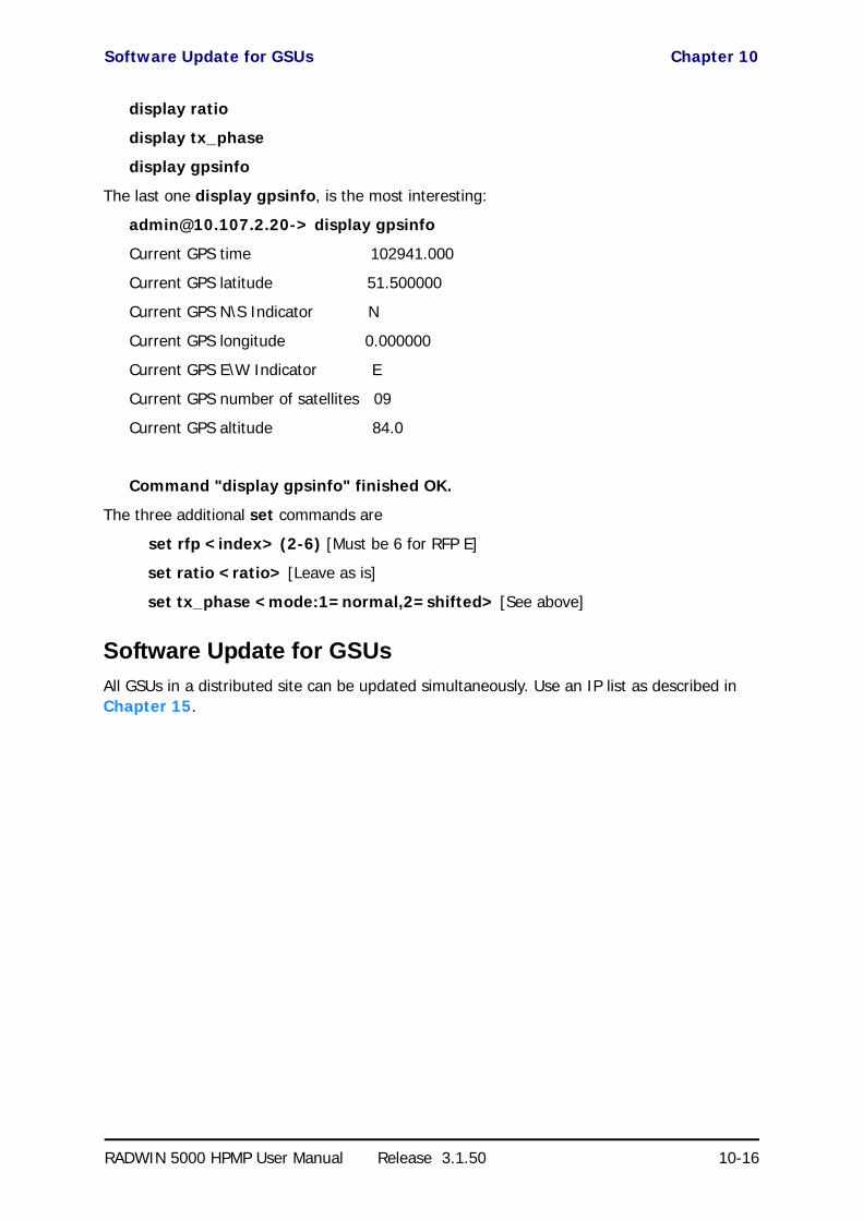
Software Update for GSUs Chapter 10
RADWIN 5000 HPMP User Manual Release 3.1.50 10-16
display ratio
display tx_phase
display gpsinfo
The last one display gpsinfo, is the most interesting:
[email protected]> display gpsinfo
Current GPS time 102941.000
Current GPS latitude 51.500000
Current GPS N\S Indicator N
Current GPS longitude 0.000000
Current GPS E\W Indicator E
Current GPS number of satellites 09
Current GPS altitude 84.0
Command "display gpsinfo" finished OK.
The three additional set commands are
set rfp <index> (2-6) [Must be 6 for RFP E]
set ratio <ratio> [Leave as is]
set tx_phase <mode:1=normal,2=shifted> [See above]
Software Update for GSUs
All GSUs in a distributed site can be updated simultaneously. Use an IP list as described in Chapter 15.

RADWIN 5000 HPMP
Point to Multipoint Broadband Wireless
USER MANUAL
RELEASE 3.1.50
Part 5: Advanced InstallationTopics
UM 5000-3150/06.11

RADWIN 5000 HPMP User Manual Release 3.1.50 11-1
Chapter 11
Software UpgradeWhat is the Software Upgrade Utility?
The RADWIN Manager provides a Software Upgrade Utility (SWU) to upgrade the software (firmware) of installed ODUs in a network. The update files may be located anywhere acces-sible by the operator.
The SWU provides for:
• Prior backup of the current files prior to upgrade
• Upgrade from a list• Delayed upgrade• Various ODU reset options
The default location of the software files is in the installation area, and can be used to restore factory defaults.

Upgrading an Installed Sector Chapter 11
RADWIN 5000 HPMP User Manual Release 3.1.50 11-2
Upgrading an Installed Sector
To upgrade software for a link:
1. In the RADWIN Manager, click the Software Upgrade button.The following detached window appears:
Figure 11-1: Software Upgrade Utility - Main window
The default sites shown in the Software Upgrade list panel belong to the currently installed sector. The list may be empty if you are running the RADWIN Manager “offline”.
2. Click Add Site to add additional sites for upgrade.
Figure 11-2: Add site options
Click Add Single Site for one site only:

Upgrading an Installed Sector Chapter 11
RADWIN 5000 HPMP User Manual Release 3.1.50 11-3
Figure 11-3: Adding a single site for upgrade
Enter the IP address of the site, the Community strings (Default: public and net-man, respectively) and then click OK. The site will appear in the Software Upgrade list box. The list can be cleared using the Clear All button.
As an alternative to adding sites one at a time, you can add sites from a prepared list using the Add from File option in Figure 11-2. The list has the following format:
<IP address>,<Read-Only community>,<Read-Write community>
3. Having created an update list, click Upgrade Package to chose the relevant files. The default files are located in the SWU subdirectory in the RADWIN Manager instal-lation area. You may see one or more of the following SWU files:
For RADWIN 5000 HPMP, always choose SWU_5k.swu.
4. You make limited changes to the list by right-clicking any line:
Figure 11-4: Software Upgrade site options
5. To back up your existing system, check Backup device software check-box. Then
click the button for a standard file dialog. The default location is the My Docu-ments directory on the managing computer or the last backup directory you used.
Table 11-1: SWU Files by product
File name Product
SWU_1k.swu WinLink 1000
SWU_2k.swu RADWIN 2000
SWU_5k.swu RADWIN 5000 HPMP
SWU_gs.swu RADWIN GSU
Note
The backup here is the same as that on page 6-1, and serves the same purpose. It provides a fallback if the upgrade proves problematic.

Upgrading an Installed Sector Chapter 11
RADWIN 5000 HPMP User Manual Release 3.1.50 11-4
6. In addition to the previous step, you may opt to perform a delayed upgrade. Check the Delayed Upgrade box, and enter the date and time for the delayed upgrade.
7. The radio buttons on the right determines how your HSUs should be reset. Bear in mind that on the one hand, a reset involves a service interruption, but on the other hand, the software upgrade will not become effective until after the reset is carried out.
8. Click Start Upgrade to commence the process. For an immediate upgrade you will be able to observe the upgrade progress from the green progress bars:
Figure 11-5: Software upgrade in progress - Note the stop button
Figure 11-6: Software upgrade completed successfully
9. Click Close to exit.
10. If you requested a delayed upgrade, a notice like this will appear in the SWU title bar:

Upgrading an Installed Sector Chapter 11
RADWIN 5000 HPMP User Manual Release 3.1.50 11-5
Caution
If one or both sites fail to update, a warning notice will be displayed.
If one site of a link update fails, you should correct the problem and update the failed site as soon as possible. If you do not, following the next reset of the updated site, you could experience a link software mismatch which may affect service. See page 9-3 for details.

RADWIN 5000 HPMP User Manual Release 3.1.50 12-1
Chapter 12
VLAN Functionality withRADWIN 5000 HPMP
VLAN Tagging - Overview
VLAN Terminology
Both the technical literature and the RADWIN Manager use the terms VLAN ID and VID inter-changeably to denote a VLAN identification number.
VLAN Background Information on the WEB
The standards defining VLAN Tagging are IEEE_802.1Q and extensions.
For general background about VLAN see http://en.wikipedia.org/wiki/Virtual_LAN.
Background information about Double Tagging also known as QinQ may be found here: http://en.wikipedia.org/wiki/802.1QinQ.
Scope of this Chapter
This chapter describes how the components of a RADWIN 5000 HPMP sector deal with tag-ging and untagging.
Requirements
It is assumed that you are familiar with VLAN usage and terminology.
VLAN Tagging
VLAN tagging enables multiple bridged networks to transparently share the same physical network link without leakage of information between networks:
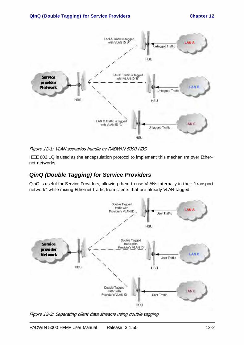
QinQ (Double Tagging) for Service Providers Chapter 12
RADWIN 5000 HPMP User Manual Release 3.1.50 12-2
Figure 12-1: VLAN scenarios handle by RADWIN 5000 HBS
IEEE 802.1Q is used as the encapsulation protocol to implement this mechanism over Ether-net networks.
QinQ (Double Tagging) for Service Providers
QinQ is useful for Service Providers, allowing them to use VLANs internally in their “transport network” while mixing Ethernet traffic from clients that are already VLAN-tagged.
Figure 12-2: Separating client data streams using double tagging

VLAN Untagging Chapter 12
RADWIN 5000 HPMP User Manual Release 3.1.50 12-3
The outer tag (representing the Provider VLAN) comes first, followed by the inner tag. In QinQ the EtherType = 0x9100. VLAN tags may be stacked three or more deep.
When using this type of “Provider Tagging” you should keep the following in mind:
• Under Provider Tagging, the system double-tags egress frames towards the Provider’s network. The system adds a tag with a VLAN ID and EtherType = 0x9100 to all frames, as configured by the service provider (Provider VLAN ID).
• The system always adds to each frame, tags with VLAN ID and EtherType = 0x9100. Therefore,• For a frame without a tag – the system will add a tag with VLAN ID and
EtherType = 0x9100 so the frame will have one tag• For a frame with a VLAN tag – the system will add a tag with VLAN ID and
EtherType = 0x9100 so the frame will be double-tagged
For a frame with a VLAN tag and a provider tag – the system will add a tag with VLAN ID and EtherType = 0x9100 so the frame will be triple-tagged and so on.
VLAN Untagging
VLAN Untagging means the removal of a VLAN or a Provider tag.
Port Functionality
VLAN functionality is supported at the MNG port of the HSU.
The HSU MNG port can be configured to handle Ethernet frames at ingress direction (where frames enter the HSU) and at egress direction (where frame exit the HSU).

Port Functionality Chapter 12
RADWIN 5000 HPMP User Manual Release 3.1.50 12-4
Ingress Direction
Table 12-1: Port settings - Ingress direction
Transparent The port ‘does nothing’ with regard to VLANs - inbound frames are left untouched.
Tag
Frames entering the HSU port without VLAN or QinQ tagging are tagged with VLAN ID and Prioritya, which are pre-configured by the user. Frames which are already tagged at ingress are not modified and pass through.
a. Priority Code Point (PCP) which refers to the IEEE 802.1p priority. It indicates the frame priority level from 0 (lowest) to 7 (highest), which can be used to prioritize different classes of traffic (voice,
video, data, etc).
Provider tag
Frames entering the HSU port are tagged with provider’s VLAN ID and Priority which are pre-configured by the user. Frames which are already tagged with Provider tagging at the ingress are not modified and pass through
.

VLAN Configuration Using the RADWIN Manager Chapter 12
RADWIN 5000 HPMP User Manual Release 3.1.50 12-5
Egress Direction
VLAN Configuration Using the RADWIN Manager
Management Traffic and Ethernet Service Separation
Managing the HBS over the Air from an HSU
If traffic VLAN tagging is in force for the HSU ingress direction and management VLAN is in use at the HBS, then the VLAN ID at the HSU ingress direction must be the same as the VLAN ID for management at the HBS.
Table 12-2: Port settings - Egress direction
Transparent The port ‘does nothing’ with regard to VLANs - outbound frames are left untouched.
Untag all
Port configured to untag user VLAD tags for all frames.
Untag double tagged
Frames are tagged QinQ with a VLAN ID, which is configured by the service provider (Provider VLAN ID). The QinQ (provider) tags are removed. User tags are passed through.
Filter
Disclaimer
If you are not a VLAN expert, please be aware that incorrect VLAN configuration may cause havoc on your network. The facilities described below are offered as a service to enable you to get best value from your RADWIN 5000 HPMP links and are provided “as is”. Under no circumstances does RADWIN accept responsibility for network system or financial damages arising from incorrect use of these VLAN facilities.

Configuration of VLAN Tagging for Ethernet Service Chapter 12
RADWIN 5000 HPMP User Manual Release 3.1.50 12-6
Configuration of VLAN Tagging for Ethernet Service
VLAN configuration is carried out per HSU. It is up to you to ensure consistency between the HSUs.
HSU VLAN tagging can only be configured from the HBS. You can not log on to a HSU directly and do it from the HSU main window. The reason is that the HSU maintains the HSU tagging information in its internal per HSU configuration record.
To set up a HSU for VLAN tagging:
1. Right click a HSU on the HBS window, and then click Configure | Ethernet | VLAN Configuration. The VLAN Configuration window is displayed:
In Disabled mode, Ethernet frames pass transparently over the radio links.
2. For Provider tagging, click the Provider Radio button:
In Provider mode, Ethernet frames are tagged with the provider’s VLAN ID before they enter into the provider’s network/backbone.
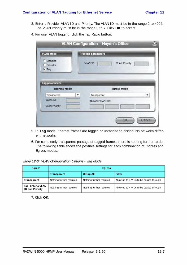
Configuration of VLAN Tagging for Ethernet Service Chapter 12
RADWIN 5000 HPMP User Manual Release 3.1.50 12-7
3. Enter a Provider VLAN ID and Priority. The VLAN ID must be in the range 2 to 4094. The VLAN Priority must be in the range 0 to 7. Click OK to accept.
4. For user VLAN tagging, click the Tag Radio button:
5. In Tag mode Ethernet frames are tagged or untagged to distinguish between differ-ent networks.
6. For completely transparent passage of tagged frames, there is nothing further to do. The following table shows the possible settings for each combination of Ingress and Egress modes:
7. Click OK.
Table 12-3: VLAN Configuration Options - Tag Mode
Ingress Egress
Transparent Untag All Filter
Transparent Nothing further required Nothing further required Allow up to 4 VIDs to be passed through
Tag: Enter a VLAN ID and Priority Nothing further required Nothing further required Allow up to 4 VIDs to be passed through

RADWIN 5000 HPMP User Manual Release 3.1.50 13-1
Chapter 13
FCC/IC DFSConsiderations
FCC 5.4GHz Device Registration
The FCC requires that devices installed within 35 km of any TDWR location should be regis-tered in the voluntary WISPA sponsored database.
The FCC has published a TDWR Location Information table that lists the exact location of all TDWR towers (see Table 13-1 at the end of the chapter).
1. When installing a 5.4 GHz device define your exact location (latitude and longitude)
2. Use the TDWR Location Information table to determine if the distance between the device and any TDWR tower is less than 35 km.
3. If the distance is less than 35 km then register the device in the voluntary WISPA sponsored database (following section)
4. Disable the frequencies between 5570 – 5680 MHz from the available channels list.
5. The frequency range between 5.600 to 5.650 GHz is not included in the available channels list.
Registering the Device
To register a device:
1. Enter the website http://www.spectrumbridge.com/udia/home.aspx and follow the instructions.
At your first entry into the site, you will be required to register as a user:

Registering the Device Chapter 13
RADWIN 5000 HPMP User Manual Release 3.1.50 13-2
2. Click the User Registration button to enter the registration page.

Registering the Device Chapter 13
RADWIN 5000 HPMP User Manual Release 3.1.50 13-3
3. Fill in the registration page and click Register.
4. To complete device registration enter the Register Device tab as shown:

Registering the Device Chapter 13
RADWIN 5000 HPMP User Manual Release 3.1.50 13-4
You are offered this:
5. Fill in the required information in the preceding web page and click the Register Device button.

TDWR Table Chapter 13
RADWIN 5000 HPMP User Manual Release 3.1.50 13-5
TDWR Table
The following table contains the latitude and longitude locations of Terminal Doppler Weather Radars (TDWR). Use this table to determine if the Master or Client device installed is within 35 km radius of a TDWR location. If one of the installed devices is within 35 km radius of any TDWR location then disable all frequencies between 5570 – 5680 MHz from the available channels list.
Table 13-1: Latitude and longitude locations of TDWRs
STATE CITY LONGITUDE LATITUDE FREQUENCY TERRAIN ELEVATION (MSL) [ft]
ANTENNA HEIGHT ABOVE TERRAIN [ft]
AZ PHOENIX W 112 09 46 N 33 25 14 5610 MHz 1024 64
CO DENVER W 104 31 35 N 39 43 39 5615 MHz 5643 64
FL FT LAUDERDALE W 080 20 39 N 26 08 36 5645 MHz 7 113
FL MIAMI W 080 29 28 N 25 45 27 5605 MHz 10 113
FL ORLANDO W 081 19 33 N 28 20 37 5640 MHz 72 97
FL TAMPA W 082 31 04 N 27 51 35 5620 MHz 14 80
FL WEST PALM BEACH W 080 16 23 N 26 41 17 5615 MHz 20 113
GA ATLANTA W 084 15 44 N 33 38 48 5615 MHz 962 113
IL MCCOOK W 087 51 31 N 41 47 50 5615 MHz 646 97
IL CRESTWOOD W 087 43 47 N 41 39 05 5645 MHz 663 113
IN INDIANAPOLIS W 086 26 08 N 39 38 14 5605 MHz 751 97
KS WICHITA W 097 26 13 N 37 30 26 5603 MHz 1270 80
KY COVINGTON CINCINNATI W 084 34 48 N 38 53 53 5610 MHz 942 97
KY LOUISVILLE W 085 36 38 N 38 02 45 5646 MHz 617 113
LA NEW ORLEANS W 090 24 11 N 30 01 18 5645 MHz 2 97
MA BOSTON W 070 56 01 N 42 09 30 5610 MHz 151 113
MD BRANDYWINE W 076 50 42 N 38 41 43 5635 MHz 233 113
MD BENFIELD W 076 37 48 N 39 05 23 5645 MHz 184 113
MD CLINTON W 076 57 43 N 38 45 32 5615 MHz 249 97
MI DETROIT W 083 30 54 N 42 06 40 5615 MHz 656 113
MN MINNEAPOLIS W 092 55 58 N 44 52 17 5610 MHz 1040 80
MO KANSAS CITY W 094 44 31 N 39 29 55 5605 MHz 1040 64
MO SAINT LOUIS W 090 29 21 N 38 48 20 5610 MHz 551 97
MS DESOTO COUNTY W 089 59 33 N 34 53 45 5610 MHz 371 113
NC CHARLOTTE W 080 53 06 N 35 20 14 5608 MHz 757 113
NC RALEIGH DURHAM W 078 41 50 N 36 00 07 5647 MHz 400 113
NJ WOODBRIDGE W 074 16 13 N 40 35 37 5620 MHz 19 113
NJ PENNSAUKEN W 075 04 12 N 39 56 57 5610 MHz 39 113
NV LAS VEGAS W 115 00 26 N 36 08 37 5645 MHz 1995 64

TDWR Table Chapter 13
RADWIN 5000 HPMP User Manual Release 3.1.50 13-6
NY FLOYD BENNETT FIELD W 073 52 49 N 40 35 20 5647 MHz 8 97
OH DAYTON W 084 07 23 N 40 01 19 5640 MHz 922 97
OH CLEVELAND W 082 00 28 N 41 17 23 5645 MHz 817 113
OH COLUMBUS W 082 42 55 N 40 00 20 5605 MHz 1037 113
OK AERO. CTR TDWR #1 W 097 37 31 N 35 24 19 5610 MHz 1285 80
OK AERO. CTR TDWR #2 W 097 37 43 N 35 23 34 5620 MHz 1293 97
OK TULSA W 095 49 34 N 36 04 14 5605 MHz 712 113
OK OKLAHOMA CITY W 097 30 36 N 35 16 34 5603 MHz 1195 64
PA HANOVER W 080 29 10 N 40 30 05 5615 MHz 1266 113
PR SAN JUAN W 066 10 46 N 18 28 26 5610 MHz 59 113
TN NASHVILLE W 086 39 42 N 35 58 47 5605 MHz 722 97
TX HOUSTON INTERCONTL W 095 34 01 N 30 03 54 5605 MHz 154 97
TX PEARLAND W 095 14 30 N 29 30 59 5645 MHz 36 80
TX DALLAS LOVE FIELD W 096 58 06 N 32 55 33 5608 MHz 541 80
TX LEWISVILLE DFW W 096 55 05 N 33 03 53 5640 MHz 554 31
UT SALT LAKE CITY W 111 55 47 N 40 58 02 5610 MHz 4219 80
VA LEESBURG W 077 31 46 N 39 05 02 5605 MHz 361 113
WI MILWAUKEE W 088 02 47 N 42 49 10 5603 MHz 820 113
Table 13-1: Latitude and longitude locations of TDWRs (Continued)
STATE CITY LONGITUDE LATITUDE FREQUENCY TERRAIN ELEVATION (MSL) [ft]
ANTENNA HEIGHT ABOVE TERRAIN [ft]

RADWIN 5000 HPMP
Point to Multipoint Broadband Wireless
USER MANUAL
RELEASE 3.1.50
Part 6: Field InstallationTopics
UM 5000-3150/06.11
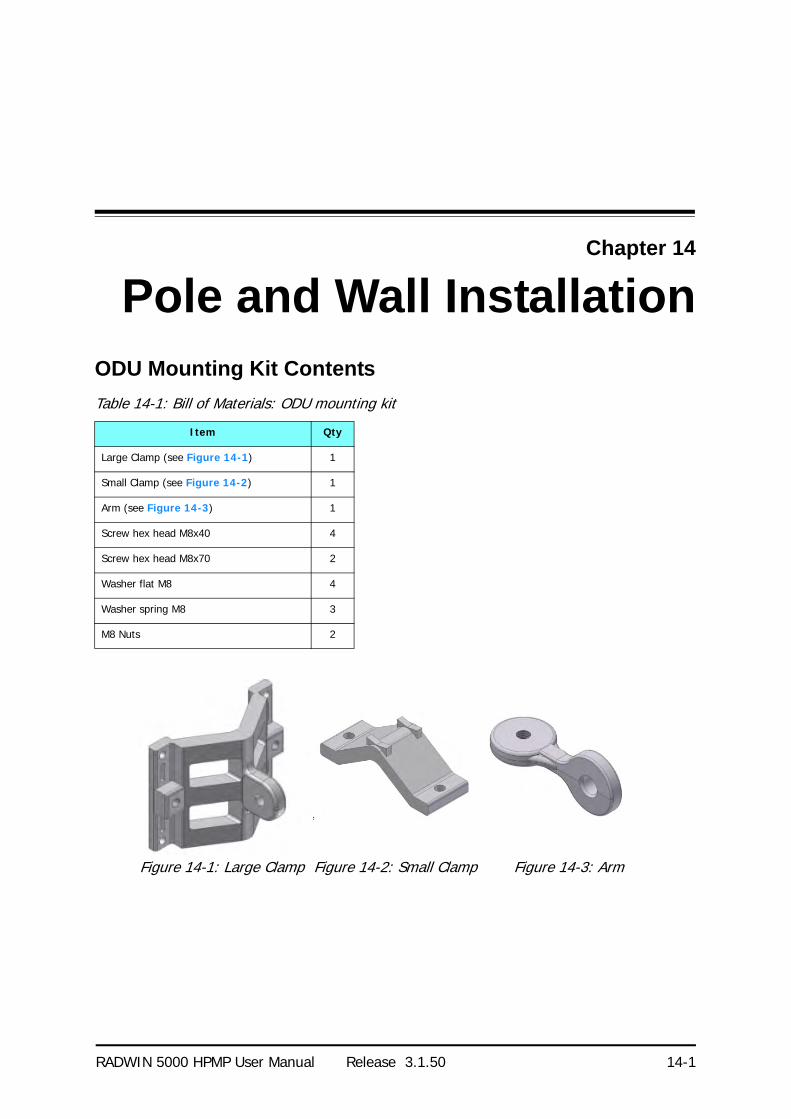
RADWIN 5000 HPMP User Manual Release 3.1.50 14-1
Chapter 14
Pole and Wall InstallationODU Mounting Kit Contents
Table 14-1: Bill of Materials: ODU mounting kit
Item Qty
Large Clamp (see Figure 14-1) 1
Small Clamp (see Figure 14-2) 1
Arm (see Figure 14-3) 1
Screw hex head M8x40 4
Screw hex head M8x70 2
Washer flat M8 4
Washer spring M8 3
M8 Nuts 2
Figure 14-1: Large Clamp Figure 14-2: Small Clamp Figure 14-3: Arm

Mounting an ODU on a Pole Chapter 14
RADWIN 5000 HPMP User Manual Release 3.1.50 14-2
Mounting an ODU on a Pole
Figure 14-4: Mounting on a pole

Mounting an ODU on a Wall Chapter 14
RADWIN 5000 HPMP User Manual Release 3.1.50 14-3
Mounting an ODU on a Wall
Figure 14-5: Mounting on a Wall

Mounting an External Antenna Chapter 14
RADWIN 5000 HPMP User Manual Release 3.1.50 14-4
Mounting an External Antenna
Optional external antennas can be mounted on a pole. The external mounting kit varies according to the specific antenna model.
Mounting a Connectorized ODU Horizontally
What follows applies to both WinLink 1000, RADWIN 2000 and RADWIN 5000 HPMP with obvious differences.
An ODU may be mounted horizontally as shown in Figure 14-6.
To mount an ODU horizontally, observe the following cautions:
1. To ensure your warranty rights for horizontally installed ODUs, make sure that the four ports ANT1, ANT2, HSS and ODU are firmly secured or moisture sealed with the supplied caps.
2. Further, ensure that cables are connected using a “water nose” as shown in Figure 14-6.
Figure 14-6: Mounted ODUs with correct “water nose”
Do not do this:
Figure 14-7: Incorrectly mounted ODU (No “water nose”)
3. If you attach an external PoE device near the ODU, the same considerations apply.

RADWIN 5000 HPMP User Manual Release 3.1.50 15-1
Chapter 15
Lightning Protection andGrounding Guidelines
Meticulous implementation of the guidelines in this chapter will provide best protection against electric shock and lightning.
The RADWIN Lightning Protection System consists of the following components:
• Grounding for the antenna coax cable• Grounding for each IDU and ODU• External Primary Lightning Protector units and grounding for the outdoor cable
• Internal ESD protection circuits over the Power/Telecom lines
Grounding for Antenna Cable
A Grounding Kit must be connected to the coax antenna cable and reliably grounded. The grounding kit is an Andrew Type 223158-2 (www.andrew.com). See Figure 15-1 below.
Warning100% protection is neither implied nor possible.
Note
This chapter is at best a guide. The actual degree of lightning protection required depends on local conditions and regulations.
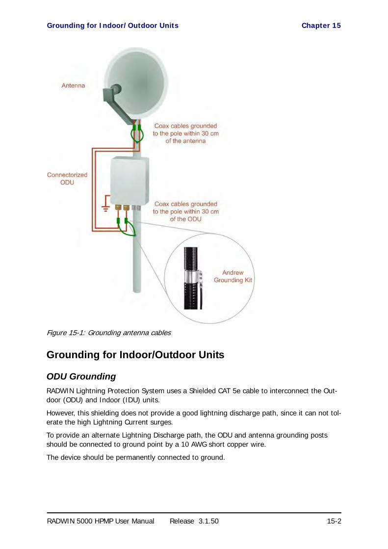
Grounding for Indoor/Outdoor Units Chapter 15
RADWIN 5000 HPMP User Manual Release 3.1.50 15-2
Figure 15-1: Grounding antenna cables
Grounding for Indoor/Outdoor Units
ODU Grounding
RADWIN Lightning Protection System uses a Shielded CAT 5e cable to interconnect the Out-door (ODU) and Indoor (IDU) units.
However, this shielding does not provide a good lightning discharge path, since it can not tol-erate the high Lightning Current surges.
To provide an alternate Lightning Discharge path, the ODU and antenna grounding posts should be connected to ground point by a 10 AWG short copper wire.
The device should be permanently connected to ground.

IDU Grounding Chapter 15
RADWIN 5000 HPMP User Manual Release 3.1.50 15-3
IDU Grounding
The IDU grounding post should be connected to the internal ground point, using a grounding wire of at least 10 AWG. The grounding wire should be connected to a grounding rod or the building grounding system.
The device should be permanently connected to ground.
The RADWIN Lightning Protection Kit
The RADWIN lightning protection kit contains the items as shown in Figure 15-2:
Figure 15-2: RADWIN Lightning Protection Kit
The lightning protector incorporates high-power gas discharge tube and current transistor protection in a single protector unit. Technical specifications are shown in Appendix A.
Using Lightning Protectors and Grounding
A Grounding Kit and lightning protector Unit must be located near the ODU and properly grounded as illustrated in Figures 15-3 and 15-4 below:

Using Lightning Protectors and Grounding Chapter 15
RADWIN 5000 HPMP User Manual Release 3.1.50 15-4
Figure 15-3: Grounding a typical pole installation

Using Lightning Protectors and Grounding Chapter 15
RADWIN 5000 HPMP User Manual Release 3.1.50 15-5
Figure 15-4: Grounding a typical wall installation
The next figure shows a close-up of the rear of grounded ODU:
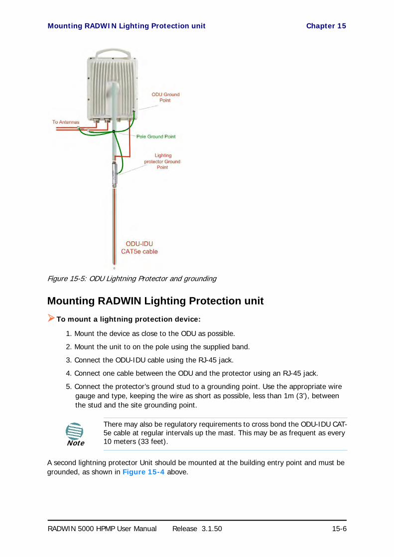
Mounting RADWIN Lighting Protection unit Chapter 15
RADWIN 5000 HPMP User Manual Release 3.1.50 15-6
Figure 15-5: ODU Lightning Protector and grounding
Mounting RADWIN Lighting Protection unit
To mount a lightning protection device:
1. Mount the device as close to the ODU as possible.
2. Mount the unit to on the pole using the supplied band.
3. Connect the ODU-IDU cable using the RJ-45 jack.
4. Connect one cable between the ODU and the protector using an RJ-45 jack.
5. Connect the protector’s ground stud to a grounding point. Use the appropriate wire gauge and type, keeping the wire as short as possible, less than 1m (3’), between the stud and the site grounding point.
A second lightning protector Unit should be mounted at the building entry point and must be grounded, as shown in Figure 15-4 above.
Note
There may also be regulatory requirements to cross bond the ODU-IDU CAT-5e cable at regular intervals up the mast. This may be as frequent as every 10 meters (33 feet).

Internal ESD Protection circuits Chapter 15
RADWIN 5000 HPMP User Manual Release 3.1.50 15-7
To mount the lightning protection at the building entry point:
1. Mount the device outside the building, located as near as possible to the entrance of the CAT 5e ODU-IDU cable.
2. Mount the unit to on the pole using the supplied band.
3. Connect the ODU-IDU cable using the RJ-45 jack.
4. Connect one cable between the IDU and the protector using an RJ-45 jack.
5. Connect the protector’s ground stud to a grounding point. Use the appropriate wire gauge and type, keeping the wire as short as possible, less than 1m (3’), between the stud and the site grounding point.
Figure 15-6: Lightning protector and grounding at building entry point
Internal ESD Protection circuits
RADWIN equipment is designed to meet the ETSI/FCC/Aus/NZ/CSA EMC and Safety require-ments. To fulfill these requirements, the system's Telecom lines at the ODU/IDU are Trans-former-isolated and include internal ESD (Electro-Static-Discharge) Protection circuits.
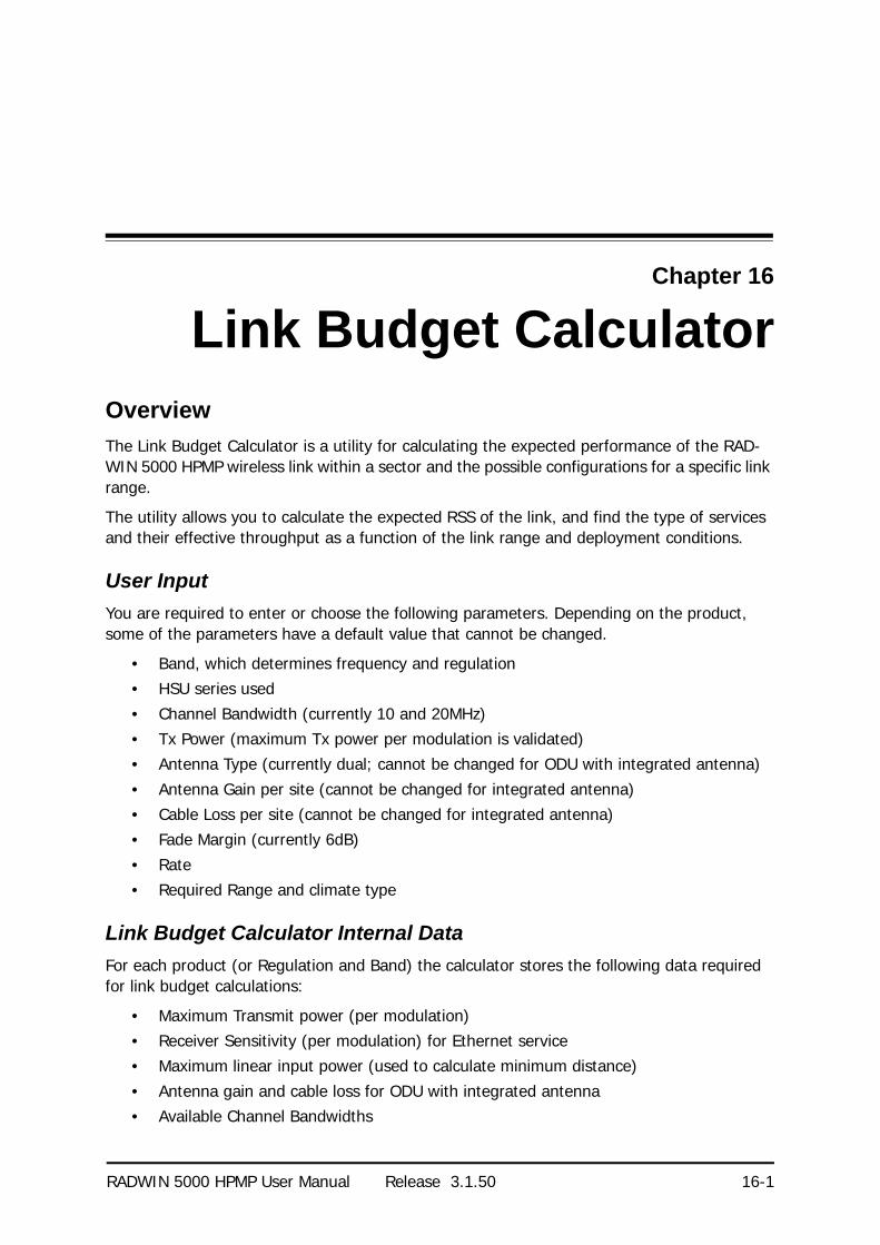
RADWIN 5000 HPMP User Manual Release 3.1.50 16-1
Chapter 16
Link Budget CalculatorOverview
The Link Budget Calculator is a utility for calculating the expected performance of the RAD-WIN 5000 HPMP wireless link within a sector and the possible configurations for a specific link range.
The utility allows you to calculate the expected RSS of the link, and find the type of services and their effective throughput as a function of the link range and deployment conditions.
User Input
You are required to enter or choose the following parameters. Depending on the product, some of the parameters have a default value that cannot be changed.
• Band, which determines frequency and regulation• HSU series used
• Channel Bandwidth (currently 10 and 20MHz)• Tx Power (maximum Tx power per modulation is validated)• Antenna Type (currently dual; cannot be changed for ODU with integrated antenna)
• Antenna Gain per site (cannot be changed for integrated antenna)• Cable Loss per site (cannot be changed for integrated antenna)• Fade Margin (currently 6dB)
• Rate• Required Range and climate type
Link Budget Calculator Internal Data
For each product (or Regulation and Band) the calculator stores the following data required for link budget calculations:
• Maximum Transmit power (per modulation)• Receiver Sensitivity (per modulation) for Ethernet service• Maximum linear input power (used to calculate minimum distance)
• Antenna gain and cable loss for ODU with integrated antenna• Available Channel Bandwidths

Calculations Chapter 16
RADWIN 5000 HPMP User Manual Release 3.1.50 16-2
Calculations
EIRP
Expected RSS and Fade Margin
where:
Site A is the transmitting site
Site B is the receiving site
PathLoss is calculated according to the free space model,
where Sensitivity is dependent on air-rate.
Min and Max Range
MinRange is the shortest range for which per air-rate.
MaxRange (with Adaptive checked) is the largest range for which , at the highest air-rate for which this relationship is true. In a
link with adaptive rate this will be the actual behavior.
MaxRange (for a given air-rate) is the largest range for which .
ServiceThe Ethernet and configured TDM trunks throughput is calculated according to internal prod-uct algorithms.
AvailabilityThe Service Availability calculation is based on the Vigants Barnett method which predicts the downtime probability based on a climate factor (C factor).
EIRP TxPower AntennaGainSiteA CableLossSiteA–+=
ExpectedRSS EIRP PathLoss AntennaGainSiteB CableLossSiteB–+–=
PathLoss 32.45 20 frequencyMHz 20 RequiredRangeKm 10
log+10
log+=
ExpectedFadeM inarg ExpectedRSS Sensitivity–=
ExpectedRSS MaxInputPower
ExpectedRSS Sensitivity
ExpectedRSS Sensitivity RequiredFadeM inarg+
Availability
1 6– 107– Cfactor frequencyGHz RequiredRangeKM 3
10
ExpectedFadeM inarg–10
------------------------------------------------------------
=

Antenna Height Chapter 16
RADWIN 5000 HPMP User Manual Release 3.1.50 16-3
Antenna HeightThe recommended antenna height required for line of sight is calculated as the sum the Fres-nel zone height and the boresight height. See About the Fresnel Zone below. Using the notation of Figure 16-1 below, splitting ExpectedRange into d1 + d2, the Fresnel zone height at distance d1 from the left hand antenna, is given by
For the most conservative setting, we take the mid-point between the antennas, setting
which gives
simplifying to .
The boresight clearance height is calculated as:
where .
About the Fresnel Zone
The Fresnel zone (pronounced "frA-nel", with a silent “s”) is an elliptically shaped conical zone of electromagnetic energy that propagates from the transmitting antenna to the receiving antenna. It is always widest in the middle of the path between the two antennas.
0.6
300frequencyGHz----------------------------------- d1 d2
d1 d2+-----------------------------------------------------------
d1 d2ExpectedRange
2-----------------------------------------= =
0.6
300frequencyGHz----------------------------------- ExpectedRange
2-----------------------------------------
2
ExpectedRange2
----------------------------------------- ExpectedRange2
-----------------------------------------+-------------------------------------------------------------------------------------------
0.52 ExpectedRangefrequencyGHz
-----------------------------------------
R2Mean
ExpectedRange2
-----------------------------------------2
+ RMean–
RMean 6367.4425Km=

About the Fresnel Zone Chapter 16
RADWIN 5000 HPMP User Manual Release 3.1.50 16-4
Figure 16-1: Fresnel zone
Fresnel loss is the path loss occurring from multi-path reflections from reflective surfaces such as water, and intervening obstacles such as buildings or mountain peaks within the Fresnel zone.
Radio links should be designed to accommodate obstructions and atmospheric conditions, weather conditions, large bodies of water, and other reflectors and absorbers of electromag-netic energy.
The Fresnel zone provides us with a way to calculate the amount of clearance that a wireless wave needs from an obstacle to ensure that the obstacle does not attenuate the signal.
There are infinitely many Fresnel zones located coaxially around the center of the direct wave. The outer boundary of the first Fresnel zone is defined as the combined path length of all paths, which are half wavelength (1/2 ) of the frequency transmitted longer than the direct path. If the total path distance is one wavelength (1 ) longer than the direct path, then the outer boundary is said to be two Fresnel zones. Odd number Fresnel zones reinforce the direct wave path signal; even number Fresnel zones cancel the direct wave path signal.
The amount of the Fresnel zone clearance is determined by the wavelength of the signal, the path length, and the distance to the obstacle. For reliability, point-to-point links are designed to have at least 60% of the first Fresnel zone clear to avoid significant attenuation.
The concept of the Fresnel zone is shown in Figure 16-1 above. The top of the obstruction does not extend far into the Fresnel zone, leaving 60% of the Fresnel zone clear; therefore, the signal is not significantly attenuated.
For more about Fresnel zone, see http://en.wikipedia.org/wiki/Fresnel_zone.

Running the Link Budget Calculator Chapter 16
RADWIN 5000 HPMP User Manual Release 3.1.50 16-5
Running the Link Budget Calculator
The Link Budget Calculator is supplied on the RADWIN Manager CD. It may be run stand-alone from the CD or from the RADWIN Manager application.
To run the Link Budget Calculator from the CD:
1. Insert the RADWIN Manager CD into the drive on the managing computer. In the window which opens, click the Link Budget Calculator option.
2. If the CD autorun application does not start by itself, then point your browser to
Z:\RADWIN\Setup\DATA\Link Budget Calculator.htm
where Z should be replaced with your own CD drive name.
To run the Link Budget Calculator from the RADWIN Manager:
• Choose Help | Link Budget Calculator from the main menu of the RADWIN Man-ager:
Figure 16-2: Accessing the Link Budget Calculator
To run the Link Budget Calculator from the Windows Start Menu:
• Go to Start | Programs | RADWIN Manager | Link Budget Calculator
However invoked, your browser displays the following page:
Figure 16-3: Link Budget window - startup
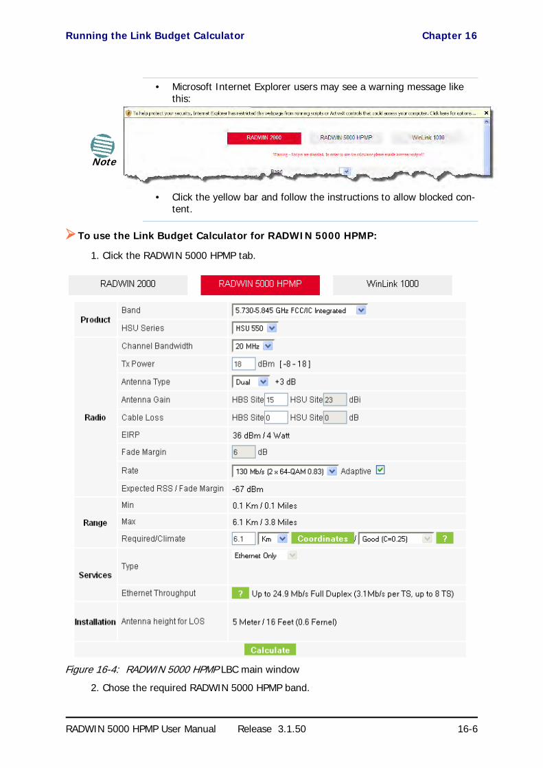
Running the Link Budget Calculator Chapter 16
RADWIN 5000 HPMP User Manual Release 3.1.50 16-6
To use the Link Budget Calculator for RADWIN 5000 HPMP:
1. Click the RADWIN 5000 HPMP tab.
Figure 16-4: RADWIN 5000 HPMP LBC main window
2. Chose the required RADWIN 5000 HPMP band.
Note
• Microsoft Internet Explorer users may see a warning message like this:
• Click the yellow bar and follow the instructions to allow blocked con-tent.
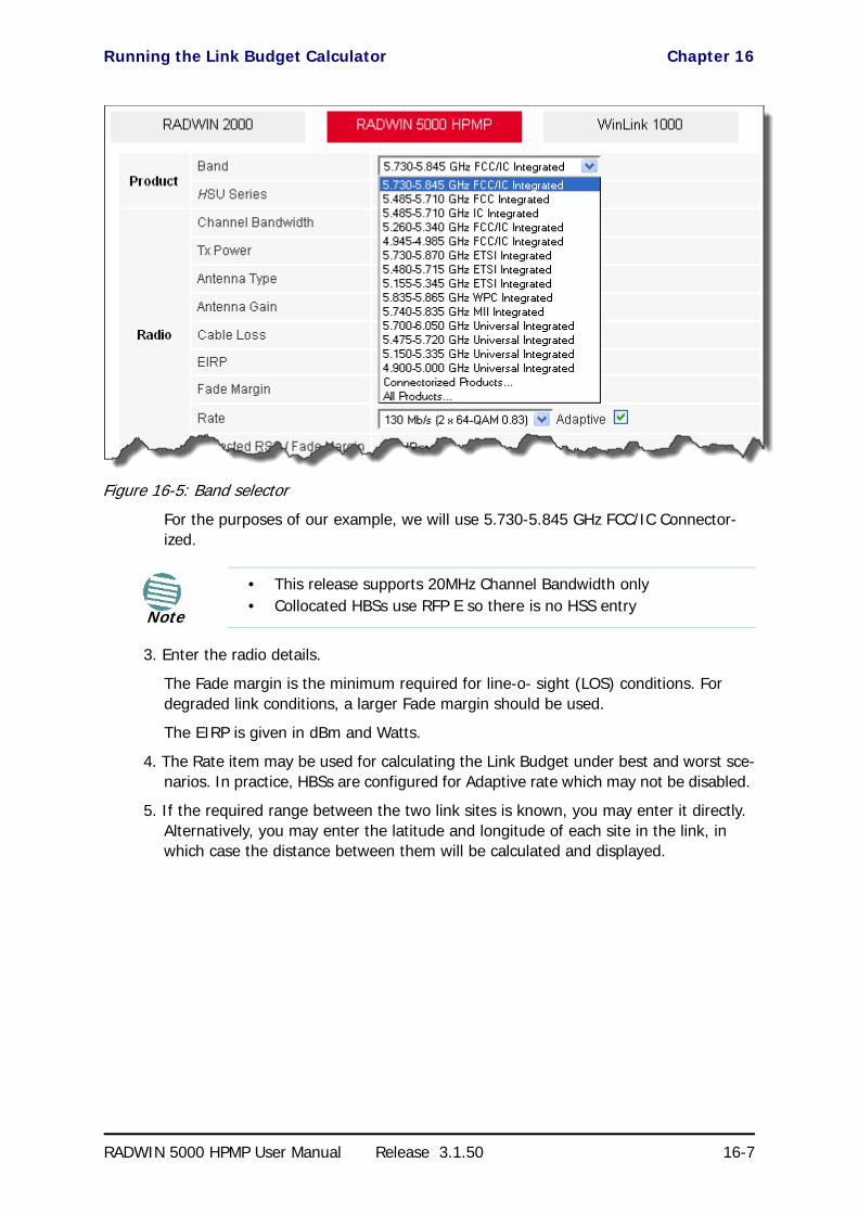
Running the Link Budget Calculator Chapter 16
RADWIN 5000 HPMP User Manual Release 3.1.50 16-7
Figure 16-5: Band selector
For the purposes of our example, we will use 5.730-5.845 GHz FCC/IC Connector-ized.
3. Enter the radio details.
The Fade margin is the minimum required for line-o- sight (LOS) conditions. For degraded link conditions, a larger Fade margin should be used.
The EIRP is given in dBm and Watts.
4. The Rate item may be used for calculating the Link Budget under best and worst sce-narios. In practice, HBSs are configured for Adaptive rate which may not be disabled.
5. If the required range between the two link sites is known, you may enter it directly. Alternatively, you may enter the latitude and longitude of each site in the link, in which case the distance between them will be calculated and displayed.
Note
• This release supports 20MHz Channel Bandwidth only• Collocated HBSs use RFP E so there is no HSS entry

Running the Link Budget Calculator Chapter 16
RADWIN 5000 HPMP User Manual Release 3.1.50 16-8
Figure 16-6: Calculation of distance from site coordinates
If for example, we enter:
Site A: 41.1°N lat 74.2°W Long
Site B: 40.8°N lat 74.0°W Long
and press Set,
the range will be calculated and displayed:
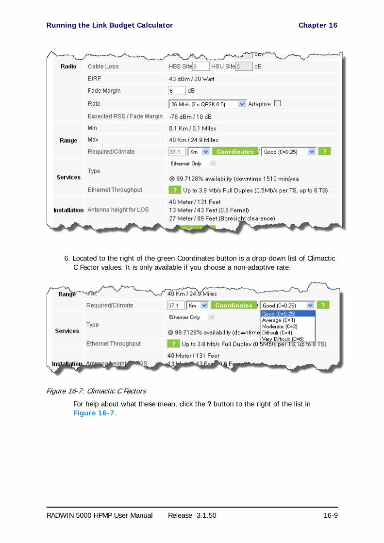
Running the Link Budget Calculator Chapter 16
RADWIN 5000 HPMP User Manual Release 3.1.50 16-9
6. Located to the right of the green Coordinates button is a drop-down list of Climactic C Factor values. It is only available if you choose a non-adaptive rate.
Figure 16-7: Climactic C Factors
For help about what these mean, click the ? button to the right of the list in Figure 16-7.

Running the Link Budget Calculator Chapter 16
RADWIN 5000 HPMP User Manual Release 3.1.50 16-10
Figure 16-8: Climactic C Factor description
In Figure 16-9 we display a map of the world showing C Factor contours:
Figure 16-9: World map showing C Factor contours
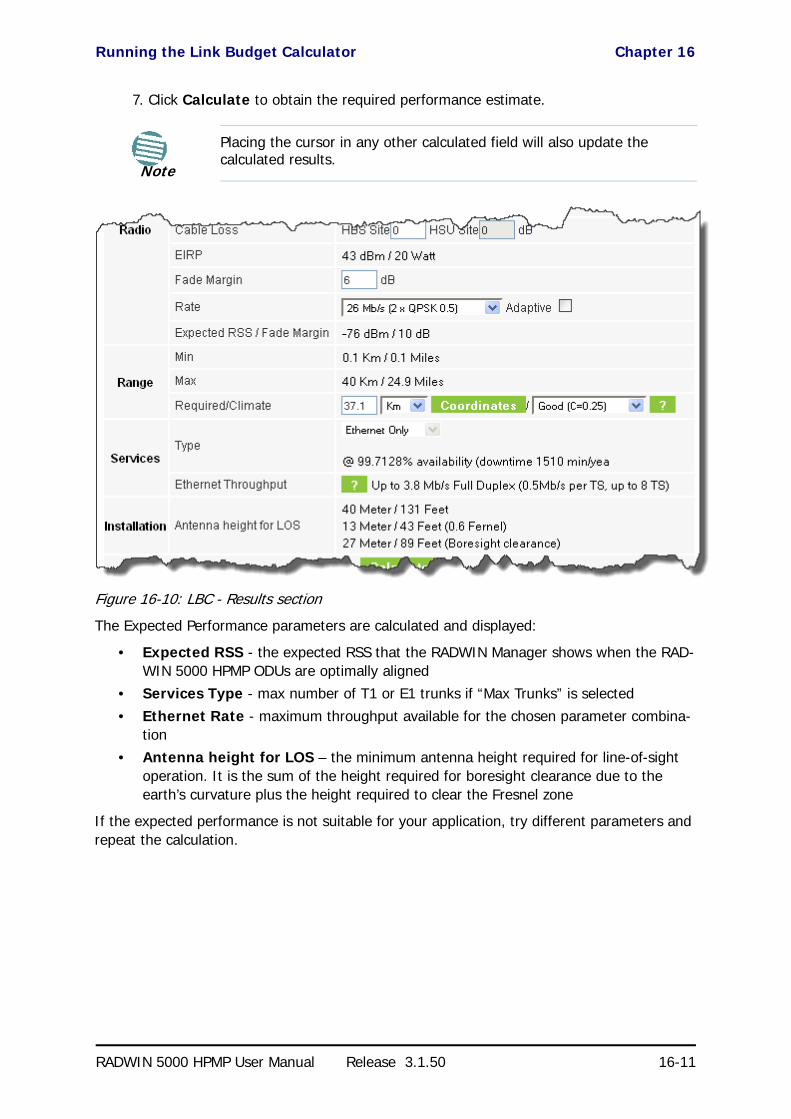
Running the Link Budget Calculator Chapter 16
RADWIN 5000 HPMP User Manual Release 3.1.50 16-11
7. Click Calculate to obtain the required performance estimate.
Figure 16-10: LBC - Results section
The Expected Performance parameters are calculated and displayed:
• Expected RSS - the expected RSS that the RADWIN Manager shows when the RAD-WIN 5000 HPMP ODUs are optimally aligned
• Services Type - max number of T1 or E1 trunks if “Max Trunks” is selected
• Ethernet Rate - maximum throughput available for the chosen parameter combina-tion
• Antenna height for LOS – the minimum antenna height required for line-of-sight operation. It is the sum of the height required for boresight clearance due to the earth’s curvature plus the height required to clear the Fresnel zone
If the expected performance is not suitable for your application, try different parameters and repeat the calculation.
Note
Placing the cursor in any other calculated field will also update the calculated results.

Product Reference
RADWIN 5000 HPMP
Point to Multipoint Broadband Wireless
USER MANUAL
RELEASE 3.1.50
Part 7: Product Reference
UM 5000-3150/06.11
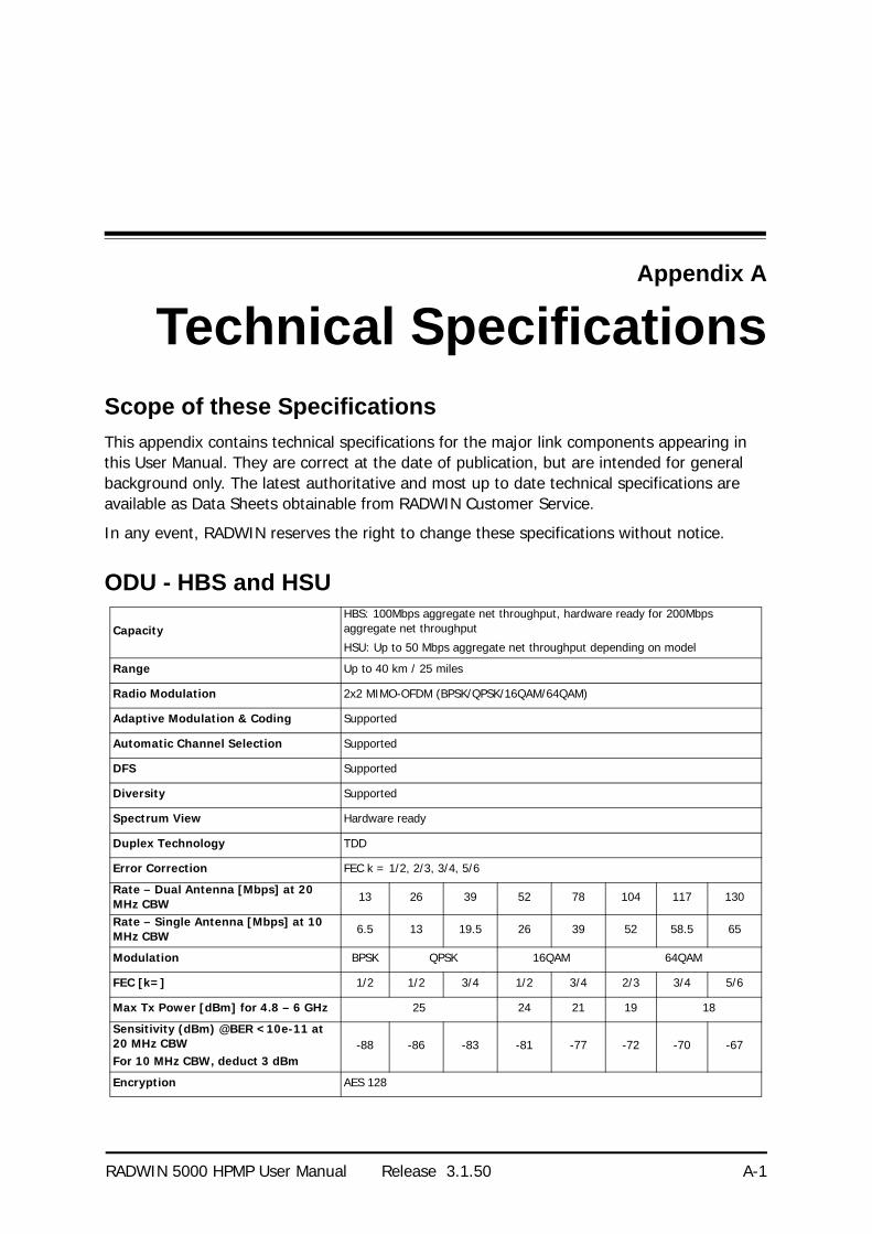
RADWIN 5000 HPMP User Manual Release 3.1.50 A-1
Appendix A
Technical SpecificationsScope of these Specifications
This appendix contains technical specifications for the major link components appearing in this User Manual. They are correct at the date of publication, but are intended for general background only. The latest authoritative and most up to date technical specifications are available as Data Sheets obtainable from RADWIN Customer Service.
In any event, RADWIN reserves the right to change these specifications without notice.
ODU - HBS and HSU
CapacityHBS: 100Mbps aggregate net throughput, hardware ready for 200Mbps aggregate net throughput
HSU: Up to 50 Mbps aggregate net throughput depending on model
Range Up to 40 km / 25 miles
Radio Modulation 2x2 MIMO-OFDM (BPSK/QPSK/16QAM/64QAM)
Adaptive Modulation & Coding Supported
Automatic Channel Selection Supported
DFS Supported
Diversity Supported
Spectrum View Hardware ready
Duplex Technology TDD
Error Correction FEC k = 1/2, 2/3, 3/4, 5/6
Rate – Dual Antenna [Mbps] at 20 MHz CBW 13 26 39 52 78 104 117 130
Rate – Single Antenna [Mbps] at 10 MHz CBW 6.5 13 19.5 26 39 52 58.5 65
Modulation BPSK QPSK 16QAM 64QAM
FEC [k=] 1/2 1/2 3/4 1/2 3/4 2/3 3/4 5/6
Max Tx Power [dBm] for 4.8 – 6 GHz 25 24 21 19 18
Sensitivity (dBm) @BER <10e-11 at 20 MHz CBWFor 10 MHz CBW, deduct 3 dBm
-88 -86 -83 -81 -77 -72 -70 -67
Encryption AES 128

ODU - HBS and HSU Appendix A
RADWIN 5000 HPMP User Manual Release 3.1.50 A-2
BandOccupied Frequency range [GHz]
Compliance Channel Bandwidth
5 MHz 10 MHz 20 MHz 40 MHz
FCC/IC 5.8 5.725 - 5.850 FCC 47CFR, Part 15, Subpart C and IC RSS-210 Yes Yes
FCC 5.4 5.475 - 5.720 FCC 47CFR, Part 15, Subpart E Yes Yes
IC 5.45.480 – 5.590
5.660 – 5.715IC RSS-210 Yes Yes
FCC/IC 5.3 5.255 - 5.345 FCC 47CFR, Part 15, Subpart E and IC RSS-210 Yes Yes
FCC/IC 4.9 4.940 - 4.990 FCC 47CFR, Part 90, Subpart Y and IC RSS-111 Yes Yes
WPC India 5.8 5.825 – 5.875 GSR-38 Yes Yes
MII China 5.8 5.730 – 5.845 MII China Yes Yes
ETSI 5.8 5.725 – 5.875 ETSI EN 302 502 Yes Yes
ETSI 5.4 5.475 – 5.720 ETSI EN 301 893 Yes Yes
ETSI 5.3 5.150 – 5.350 ETSI EN 301 893 Yes Yes
Universal 6.0 5.690– 6.060
N/A
Yes Yes
Universal 5.9 5.730 – 5.960 Yes Yes
Universal 5.4 5.465 – 5.720 Yes Yes
Universal 5.3 5.140 – 5.345 Yes Yes
Universal 4.9 4.890 - 5.010 Yes Yes
HBS with Integrated Antenna 37.1/14.84(W) x 37.1/14.84(H) x 9.00/3.6(D) cm/in; 3.5 kg / 7 lbs
HBS/HSU Connectorized 19.5/7.7(W) x 27.0/10.8(H) x 5.5/2.2(D) cm/in; 1.8 kg / 3.6 lbs
HSU SFF (Embedded antenna) 19.5/7.7(W) x 27.0/10.8(H) x 7/2.8(D) cm/in; 1.8 kg / 3.6 lbs
Power Feeding Dual feeding, -20 to -60 VDC (AC/DC converter is available)
Power Consumption - alone HBS: <25W, HSU: <20W
ArchitectureODU: Outdoor Unit with Integrated Antenna, Connectorized for External Antenna or Embedded
PoE device for Ethernet only
ODU to PoE Interface
HBS: • Outdoor RADWIN CAT-5e cable. maximum cable length: 100m for 10/
100BaseT.• Outdoor RADWIN CAT-5e cable. maximum cable length: 75m for
1000BaseT.
HSU:
Outdoor CAT-5e cable; maximum cable length: 100 m (10/100BaseT)
Management Application (per sector) RADWIN Manager
Protocol SNMP and Telnet
NMS RADWIN NMS - RNMS
Operating Temperatures HBS/HSU: -35°C to +60°C / -31°F to +140°F
Humidity HBS/HSU: Up to 100% non-condensing, IP67
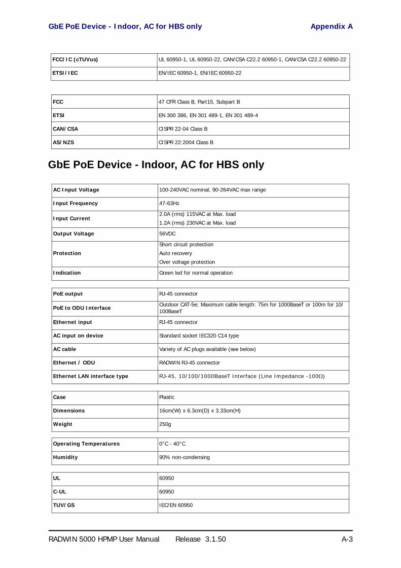
GbE PoE Device - Indoor, AC for HBS only Appendix A
RADWIN 5000 HPMP User Manual Release 3.1.50 A-3
GbE PoE Device - Indoor, AC for HBS only
FCC/IC (cTUVus) UL 60950-1, UL 60950-22, CAN/CSA C22.2 60950-1, CAN/CSA C22.2 60950-22
ETSI/IEC EN/IEC 60950-1, EN/IEC 60950-22
FCC 47 CFR Class B, Part15, Subpart B
ETSI EN 300 386, EN 301 489-1, EN 301 489-4
CAN/CSA CISPR 22-04 Class B
AS/NZS CISPR 22:2004 Class B
AC Input Voltage 100-240VAC nominal, 90-264VAC max range
Input Frequency 47-63Hz
Input Current2.0A (rms) 115VAC at Max. load
1.2A (rms) 230VAC at Max. load
Output Voltage 56VDC
Protection
Short circuit protection
Auto recovery
Over voltage protection
Indication Green led for normal operation
PoE output RJ-45 connector
PoE to ODU Interface Outdoor CAT-5e; Maximum cable length: 75m for 1000BaseT or 100m for 10/100BaseT
Ethernet input RJ-45 connector
AC input on device Standard socket IEC320 C14 type
AC cable Variety of AC plugs available (see below)
Ethernet / ODU RADWIN RJ-45 connector
Ethernet LAN interface type RJ-45, 10/100/1000BaseT Interface (Line Impedance -100)
Case Plastic
Dimensions 16cm(W) x 6.3cm(D) x 3.33cm(H)
Weight 250g
Operating Temperatures 0°C - 40°C
Humidity 90% non-condensing
UL 60950
C-UL 60950
TUV/GS IEC/EN 60950

PoE Device - Indoor, AC Appendix A
RADWIN 5000 HPMP User Manual Release 3.1.50 A-4
PoE Device - Indoor, AC
ESD 61000-4-2
RS 61000-4-3
EFT 61000-4-4
Surge 61000-4-5
CS 61000-4-6
DIPS 61000-4-11
EMI FCC part 15 class B, CISPR Pub 22 class B
AC Input Voltage 100-240VAC nominal, 85-265VAC max range
Input Frequency 47-63Hz
Input Current 1.5A max at 90VAC, 0.75A max at 265VAC
Output Voltage and Current 55VDC, 0-1A Range 50-58VDC
Protection
Short circuit protection
Auto recovery
Over voltage protection
Indication Green led for normal operation
Ethernet LAN interface type RJ-45, 10/100BaseT Interface (Line Impedance -100)
PoE to ODU Interface Outdoor CAT-5e; Maximum cable length: 100m for 10/100BaseT
AC Standard socket IEC320 C14 type
ODU (PoE Port) RJ-45 connector
Case Plastic
Dimensions 16cm(W) x 6.3cm(D) x 3.33cm(H)
Weight 250g
Operating Temperatures 0°C - 40°C
Humidity 90% non-condensing
UL 60950
C-UL 60950
TUV/GS IEC/EN 60950
ESD 61000-4-2
RS 61000-4-3
EFT 61000-4-4

PoE Device - Outdoor, DC Appendix A
RADWIN 5000 HPMP User Manual Release 3.1.50 A-5
PoE Device - Outdoor, DC
GSU
Surge 61000-4-5
CS 61000-4-6
DIPS 61000-4-11
EMI FCC part 15 class B, CISPR Pub 22 class B
Input voltage range -20 to -60 VDC (single input)
Output voltage 48VDC / 0.6A
Power Consumption 0.5W (not including radio)
ProtectionsDifferential - 15KW
Common – 3KW
Ethernet LAN interface type RJ-45, 10/100BaseT Interface (Line Impedance -100)
DC input 2 pins connector
PoE to ODU Interface Outdoor CAT-5e; Maximum cable length: 100m for 10/100BaseT
ODU (PoE Port) RJ45
Dimensions 24.5cm(H) x 13.5cm(W) x 4.0cm(D)
Weight 1.0kg/2.2lbs
Enclosure All weather cases
Operating Temperatures -35C - 60C / -31F - 140F
Humidity Up to 100% non-condensing
StandardsIEC 60721-3-4 Class 4M5
IP67
FCC/IEC/ CAN/CSA Designed to meet 60950-1, 60950-22
ETSI Designed to meet EN 300 386 V1.3.2; EN 301 489-1 V1.4.1
FCC Designed to meet CFR47 Class B, Part15, Subpart B
CAN/CSA Designed to meet ICES-003:2004 Class B
AS/NZS Designed to meet CISPR 22:2006 class B
Architecture Outdoor Unit Connectorized for External GPS Antenna
GSU to PoE Interface Outdoor CAT-5e cable; Maximum cable length: 100 m

Antenna Characteristics Appendix A
RADWIN 5000 HPMP User Manual Release 3.1.50 A-6
Antenna Characteristics
An antenna is the radiating and receiving element from which the radio signal, in the form of RF power, is radiated to its surroundings and vice versa. The transmission range is a function of the antenna gain and transmitting power. These factors are limited by country regulations.
The RADWIN 5000 HPMP may be operated with an integrated antenna attached to the HSU unit, or with an external antenna wired to the HBS/HSU via a N-type connectors. All cables and connections must be connected correctly to reduce losses. The required antenna imped-ance is 50Ω.
Dimensions 24.5cm(H) x 13.5cm(W) x 4.0cm(D)
Weight 1.0kg/2.2lbs
Power Feeding Power provided by PoE device
Max Power Dissipation 10Watt
Operating Temperature Range -35°C to + 60°C / -13°F to 140°F
Humidity 100% condensing, IP67
EN/IEC Designed to meet EN/IEC 60950-1, 60950-22
FCC Designed to meet 47 CFR Class B, Part15, Subpart B
ETSI Designed to meet EN 300 386 V1.3.3; EN 301 489-4 V1.3.1; EN 301 489-1
CAN/CSA-CEI/IEC Designed to meet CISPR 22-02
AS/NZS Designed to meet CISPR22: 2006 Class B

RADWIN 5000 HPMP User Manual Release 3.1.50 B-1
Appendix B
Wiring SpecificationsODU-PoE Cable (HBS and HSU)
The ODU-PoE cable is shielded/outdoor class CAT-5e, 4 twisted-pair 24 AWG terminated with RJ-45 connectors on both ends. A cable gland on the ODU side provides hermetic sealing.
The following table shows the connector pinout:
HBS/HSS Unit Connection Pinout
Table B-1: ODU-PoE RJ-45 Connector Pinout
Function Color IDU ODU
Ethernet (RxN) White/Green 1 1
Ethernet (RxT) Green 2 2
Ethernet (TxT) White/Orange 3 3
Ethernet (TxN) Orange 6 6
Power (+) Blue 4 4
Power (+) White/Blue 5 5
Power () White/Brown 7 7
Power () Brown 8 8
Table B-2: HBS/HSS Unit Connection Pinout
Color ODU RJ-45
HSS UNIT RJ-45
White/Green 1 1
GreenNot connected
White/Orange
Orange 6 6
Blue 4 4
White/Blue 5 5

User Port Connectors Appendix B
RADWIN 5000 HPMP User Manual Release 3.1.50 B-2
User Port Connectors
LAN Port
The LAN 10/100BaseT interface terminates in an 8-pin RJ-45 connector, wired in accordance to Table B-3.
DC Power Terminals
DC PoE
White/Brown 7 7
Brown 8 8
Table B-3: Fast Ethernet Connector Pinout
Function Signal Pin
Transmit Data (positive) TD (+) 1
Transmit Data (negative) TD (–) 2
Receive Data (positive) RD (+) 3
Receive Data (negative) RD (–) 6
Table B-4: Terminal Block 2-pin -48VDC
Function Pin
+ Right
– Left
Table B-2: HBS/HSS Unit Connection Pinout (Continued)
Color ODU RJ-45
HSS UNIT RJ-45

RADWIN 5000 HPMP User Manual Release 3.1.50 C-1
Appendix C
MIB ReferenceIntroduction
About the MIB
The RADWIN MIB is a set of APIs that enables external applications to control RADWIN equipment.
The MIB is divided into public and a private API groups:
• Public: RFC-1213 (MIB II) variables, RFC-1214 (MIB II) System and Interfaces sec-tions
• Private: Controlled by RADWIN and supplements the public group.
This appendix describes the public and private MIB used by RADWIN.
Terminology
The following terms are used in this appendix.
In addition, the MIB uses internally, the older notions of Local site and Remote site where this manual would use site A and site B.
To avoid burdening the reader, this appendix will follow the MIB usage.
Interface API
Control Method
The RADWIN Manager application provides all the means to configure and monitor a RADWIN 5000 HPMP link, communicating with the SNMP agent in each ODU. Each SNMP agent con-
Term Meaning
MIB Management Information Base
API Application Programming Interface
SNMP Simple Network Management Protocol
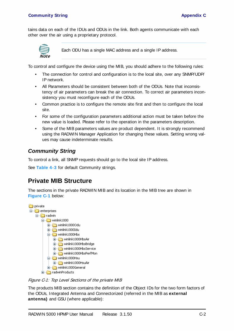
Community String Appendix C
RADWIN 5000 HPMP User Manual Release 3.1.50 C-2
tains data on each of the IDUs and ODUs in the link. Both agents communicate with each other over the air using a proprietary protocol.
To control and configure the device using the MIB, you should adhere to the following rules:
• The connection for control and configuration is to the local site, over any SNMP/UDP/IP network.
• All Parameters should be consistent between both of the ODUs. Note that inconsis-tency of air parameters can break the air connection. To correct air parameters incon-sistency you must reconfigure each of the ODUs.
• Common practice is to configure the remote site first and then to configure the local site.
• For some of the configuration parameters additional action must be taken before the new value is loaded. Please refer to the operation in the parameters description.
• Some of the MIB parameters values are product dependent. It is strongly recommend using the RADWIN Manager Application for changing these values. Setting wrong val-ues may cause indeterminate results.
Community String
To control a link, all SNMP requests should go to the local site IP address.
See Table 4-3 for default Community strings.
Private MIB Structure
The sections in the private RADWIN MIB and its location in the MIB tree are shown in Figure C-1 below:
Figure C-1: Top Level Sections of the private MIB
The products MIB section contains the definition of the Object IDs for the two form factors of the ODUs, Integrated Antenna and Connectorized (referred in the MIB as external antenna) and GSU (where applicable):
NoteEach ODU has a single MAC address and a single IP address.

MIB Parameters Appendix C
RADWIN 5000 HPMP User Manual Release 3.1.50 C-3
Figure C-2: Product MIB
The GpsSynchronizerFamily MIB defines the GSU.
The general MIB include a single generic parameter that is used by all traps as a trap descrip-tion parameter.
MIB Parameters
The following section describes all of the MIB parameters. The MIB parameters follow the fol-lowing naming convention:
<winlink1000><Section 1>...<Section n><Parameter Name>
For each of the configuration and control parameters (parameters with read-write access), the “Description” column describes when the new value is effective. It is recommended that you perform the appropriate action to make the values affective immediately after any change. Where a change is required on both sides of the link, it is recommended that you change both sides of the link first and then perform the action.
Supported Variables from the RFC 1213 MIB
Table C-1: Supported RFC 1213 Variables (Sheet 1 of 2)Name OID Type
Acces
s
Description
ifIndex .1.3.6.1.2.1.2.2.1.1.xa Integer RO A unique value for each interface.Its value ranges between 1 and the value of ifNumber.The value for each interface must remain constant at least from one re-initialization of the entity's network management system to the next re-initialization.
ifDescr .1.3.6.1.2.1.2.2.1.2 DisplayString RO A textual string containing information about the interface.This string should include the name of the manufacturer, the product name and the version of the hardware interface.
ifType .1.3.6.1.2.1.2.2.1.3 Integer RO The type of interface, distinguished according to the physical/link protocol(s) immediately `below' the network layer in the protocol stack.

Supported Variables from the RFC 1213 MIB Appendix C
RADWIN 5000 HPMP User Manual Release 3.1.50 C-4
ifSpeed .1.3.6.1.2.1.2.2.1.5 Gauge RO An estimate of the interface's current bandwidth in bits per second.For interfaces which do not vary in bandwidth or for those where no accurate estimation can be made, this object should ontain the nominal bandwidth.
ifPhysAddress .1.3.6.1.2.1.2.2.1.6 Phys-Address RO The interface's address at the protocol layer immediately `below' the network layer in the protocol stack. For interfaces which do not have such an address (e.g., a serial line), this object should contain an octet string of zero length.
ifAdminStatus .1.3.6.1.2.1.2.2.1.7 Integer RW The desired state of the interface. The testing(3) state indicates that no operational packets can be passed.
ifOperStatus .1.3.6.1.2.1.2.2.1.8 Integer RO The current operational state of the interface. The testing(3) state indicates that no operational packets can be passed.
ifInOctets .1.3.6.1.2.1.2.2.1.10.x Counter RO The total number of octets received on the interface, including framing characters.
ifInUcastPkts .1.3.6.1.2.1.2.2.1.11.x Counter RO The number of Subnetwork-unicast packets delivered to a higher-layer protocol.
ifInNUcastPkts .1.3.6.1.2.1.2.2.1.12.x Counter RO The number of non-unicast (i.e., Subnetwork- broadcast or Subnetwork-multicast) packets delivered to a higher-layer protocol.
ifInErrors .1.3.6.1.2.1.2.2.1.14.x Counter RO The number of inbound packets that contained errors preventing them from being deliverable to a higher-layer protocol.
ifOutOctets .1.3.6.1.2.1.2.2.1.16.x Counter RO The total number of octets transmitted out of the interface, including framing characters.
ifOutUcastPkts .1.3.6.1.2.1.2.2.1.17.x Counter RO The total number of packets that higher-level protocols requested be transmitted to a Subnetwork-unicast address, including those that were discarded or not sent.
ifOutNUcastPkts .1.3.6.1.2.1.2.2.1.18.x Counter RO The total number of packets that higher-level protocols requested be transmitted to a non- unicast (i.e., a Subnetwork-broadcast or Subnetwork-multicast) address, including those that were discarded or not sent.
a. x is the interface ID
Table C-1: Supported RFC 1213 Variables (Sheet 2 of 2)Name OID Type
Acc
ess
Description

Private MIB Parameters Appendix C
RADWIN 5000 HPMP User Manual Release 3.1.50 C-5
Private MIB ParametersTable C-2: Private MIB Parameters (Sheet 1 of 23)Name OID Type
Ac
cess
Description
winlink1000OduAdmProductType 1.3.6.1.4.1.4458.1000.1.1.1 DisplayString RO ODU configuration description.
winlink1000OduAdmHwRev 1.3.6.1.4.1.4458.1000.1.1.2 DisplayString RO ODU Hardware Version.
winlink1000OduAdmSwRev 1.3.6.1.4.1.4458.1000.1.1.3 DisplayString RO ODU Software Version.
winlink1000OduAdmLinkName 1.3.6.1.4.1.4458.1000.1.1.4 DisplayString RW Link Name. A change is effective immediately.
winlink1000OduAdmResetCmd 1.3.6.1.4.1.4458.1000.1.1.5 Integer RW Reset Command. A set command with a value of 3 will cause a device reset. HBS only: A set command with a value of 4 will cause a device reset for the entire sector. The read value is always 0.
winlink1000OduAdmAddres 1.3.6.1.4.1.4458.1000.1.1.6 IpAddress RW ODU IP address. A change is effective after reset. The parameter is kept for backward compatibility. Using the alternative parameter: winlink1000OduAdmIpParamsCnfg is recommended.
winlink1000OduAdmMask 1.3.6.1.4.1.4458.1000.1.1.7 IpAddress RW ODU Subnet Mask. A change is effective after reset. The parameter is kept for backward compatibility. Using the alternative parameter: winlink1000OduAdmIpParamsCnfg is recommended.
winlink1000OduAdmGateway 1.3.6.1.4.1.4458.1000.1.1.8 IpAddress RW ODU default gateway. A change is effective after reset. The parameter is kept for backward compatibility. Using the alternative parameter: winlink1000OduAdmIpParamsCnfg is recommended.
winlink1000OduAdmBroadcast 1.3.6.1.4.1.4458.1000.1.1.10 Integer RW This parameter is reserved for the Manager application provided with the product.
winlink1000OduAdmHostsTable N/A Trap destinations table. Each trap destination is defined by an IP address and a UDP port. Up to 10 addresses can be configured.
winlink1000OduAdmHostsEntry N/A Trap destinations table entry. INDEX winlink1000OduAdmHostsIndex
winlink1000OduAdmHostsIndex RO Trap destinations table index.
winlink1000OduAdmHostsIp 1.3.6.1.4.1.4458.1000.1.1.12.1.2 IpAddress RW Trap destination IP address. A change is effective immediately.
winlink1000OduAdmHostsPort 1.3.6.1.4.1.4458.1000.1.1.12.1.3 Integer RW UDP port of the trap destination. A change is effective immediately.
winlink1000OduBuzzerAdminState 1.3.6.1.4.1.4458.1000.1.1.13 Integer RW This parameter controls the activation of the buzzer while the unit is in install mode. A change is effective immediately. The valid values are: disabled (0) enabledAuto (1) enabledConstantly(2).
winlink1000OduProductId 1.3.6.1.4.1.4458.1000.1.1.14 DisplayString RO This parameter is reserved for the Manager application provided with the product.
winlink1000OduReadCommunity 1.3.6.1.4.1.4458.1000.1.1.15 DisplayString RW Read Community String. This parameter always returns ***** when retrieving its value. It is used by the Manager application to change the Read Community String. The SNMP agent accepts only encrypted values.
winlink1000OduReadWriteCommunity 1.3.6.1.4.1.4458.1000.1.1.16 DisplayString RW Read/Write Community String. This parameter always returns ***** when retrieving its value. It is used by the Manager application to change the Read/Write Community String. The SNMP agent accepts only encrypted values.
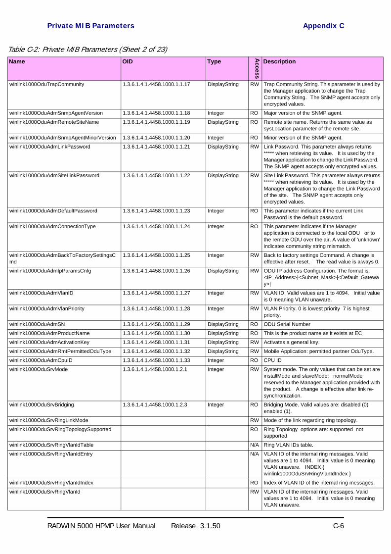
Private MIB Parameters Appendix C
RADWIN 5000 HPMP User Manual Release 3.1.50 C-6
winlink1000OduTrapCommunity 1.3.6.1.4.1.4458.1000.1.1.17 DisplayString RW Trap Community String. This parameter is used by the Manager application to change the Trap Community String. The SNMP agent accepts only encrypted values.
winlink1000OduAdmSnmpAgentVersion 1.3.6.1.4.1.4458.1000.1.1.18 Integer RO Major version of the SNMP agent.
winlink1000OduAdmRemoteSiteName 1.3.6.1.4.1.4458.1000.1.1.19 DisplayString RO Remote site name. Returns the same value as sysLocation parameter of the remote site.
winlink1000OduAdmSnmpAgentMinorVersion 1.3.6.1.4.1.4458.1000.1.1.20 Integer RO Minor version of the SNMP agent.
winlink1000OduAdmLinkPassword 1.3.6.1.4.1.4458.1000.1.1.21 DisplayString RW Link Password. This parameter always returns ***** when retrieving its value. It is used by the Manager application to change the Link Password. The SNMP agent accepts only encrypted values.
winlink1000OduAdmSiteLinkPassword 1.3.6.1.4.1.4458.1000.1.1.22 DisplayString RW Site Link Password. This parameter always returns ***** when retrieving its value. It is used by the Manager application to change the Link Password of the site. The SNMP agent accepts only encrypted values.
winlink1000OduAdmDefaultPassword 1.3.6.1.4.1.4458.1000.1.1.23 Integer RO This parameter indicates if the current Link Password is the default password.
winlink1000OduAdmConnectionType 1.3.6.1.4.1.4458.1000.1.1.24 Integer RO This parameter indicates if the Manager application is connected to the local ODU or to the remote ODU over the air. A value of 'unknown' indicates community string mismatch.
winlink1000OduAdmBackToFactorySettingsCmd
1.3.6.1.4.1.4458.1000.1.1.25 Integer RW Back to factory settings Command. A change is effective after reset. The read value is always 0.
winlink1000OduAdmIpParamsCnfg 1.3.6.1.4.1.4458.1000.1.1.26 DisplayString RW ODU IP address Configuration. The format is: <IP_Address>|<Subnet_Mask>|<Default_Gateway>|
winlink1000OduAdmVlanID 1.3.6.1.4.1.4458.1000.1.1.27 Integer RW VLAN ID. Valid values are 1 to 4094. Initial value is 0 meaning VLAN unaware.
winlink1000OduAdmVlanPriority 1.3.6.1.4.1.4458.1000.1.1.28 Integer RW VLAN Priority. 0 is lowest priority 7 is highest priority.
winlink1000OduAdmSN 1.3.6.1.4.1.4458.1000.1.1.29 DisplayString RO ODU Serial Number
winlink1000OduAdmProductName 1.3.6.1.4.1.4458.1000.1.1.30 DisplayString RO This is the product name as it exists at EC
winlink1000OduAdmActivationKey 1.3.6.1.4.1.4458.1000.1.1.31 DisplayString RW Activates a general key.
winlink1000OduAdmRmtPermittedOduType 1.3.6.1.4.1.4458.1000.1.1.32 DisplayString RW Mobile Application: permitted partner OduType.
winlink1000OduAdmCpuID 1.3.6.1.4.1.4458.1000.1.1.33 Integer RO CPU ID
winlink1000OduSrvMode 1.3.6.1.4.1.4458.1000.1.2.1 Integer RW System mode. The only values that can be set are installMode and slaveMode; normalMode reserved to the Manager application provided with the product. A change is effective after link re-synchronization.
winlink1000OduSrvBridging 1.3.6.1.4.1.4458.1000.1.2.3 Integer RO Bridging Mode. Valid values are: disabled (0) enabled (1).
winlink1000OduSrvRingLinkMode RW Mode of the link regarding ring topology.
winlink1000OduSrvRingTopologySupported RO Ring Topology options are: supported not supported
winlink1000OduSrvRingVlanIdTable N/A Ring VLAN IDs table.
winlink1000OduSrvRingVlanIdEntry N/A VLAN ID of the internal ring messages. Valid values are 1 to 4094. Initial value is 0 meaning VLAN unaware. INDEX winlink1000OduSrvRingVlanIdIndex
winlink1000OduSrvRingVlanIdIndex RO Index of VLAN ID of the internal ring messages.
winlink1000OduSrvRingVlanId RW VLAN ID of the internal ring messages. Valid values are 1 to 4094. Initial value is 0 meaning VLAN unaware.
Table C-2: Private MIB Parameters (Sheet 2 of 23)Name OID Type
Acc
ess
Description

Private MIB Parameters Appendix C
RADWIN 5000 HPMP User Manual Release 3.1.50 C-7
winlink1000OduSrvRingEthStatus RO Represents the Ethernet service blocking state of a Rings link
winlink1000OduSrvRingMaxAllowedTimeFromLastRpm
RW Defines the minimal time (in ms) required for determination of ring failure.
winlink1000OduSrvRingWTR RW Defines the minimal time (in ms) required for ring recovery.
winlink1000OduSrvQoSMode RW Mode of QoS feature.
winlink1000OduSrvQoSConfTable N/A QoS configuration table.
winlink1000OduSrvQoSConfEntry N/A QoS configuration table. INDEX winlink1000OduSrvQoSConfIndex
winlink1000OduSrvQoSConfIndex RO Index of QoS Configuration.
winlink1000OduSrvConfVlanQGroups RO Frames classification according to VLAN Priority IDs.
winlink1000OduSrvConfDiffservQGroups RO Frames classification according to Diffserv.
winlink1000OduSrvConfQueMir RW Desired Private MIR.
winlink1000OduSrvConfQueWeight RW QoS queueu's weights in percent.
winlink1000OduSrvQoSVlanQGroupsSetStr RW Frames classification according to VLAN IDs string for set.
winlink1000OduSrvQoSDiffservQGroupsSetStr RW Frames classification according to Diffserv IDs string for set.
winlink1000OduSrvQoSMaxRTQuePercent RO Maximal percent for RT & NRT queues.
winlink1000OduEthernetRemainingRate 1.3.6.1.4.1.4458.1000.1.3.1 Integer RO Current Ethernet bandwidth in bps.
winlink1000OduEthernetIfTable N/A ODU Ethernet Interface table.
winlink1000OduEthernetIfEntry N/A ODU Ethernet Interface table entry. INDEX winlink1000OduEthernetIfIndex
winlink1000OduEthernetIfIndex 1.3.6.1.4.1.4458.1000.1.3.2.1.1 Integer RO ODU Ethernet Interface Index.
winlink1000OduEthernetIfAddress 1.3.6.1.4.1.4458.1000.1.3.2.1.5 DisplayString RO ODU MAC address.
winlink1000OduEthernetIfAdminStatus 1.3.6.1.4.1.4458.1000.1.3.2.1.6 Integer RW Required state of the interface.
winlink1000OduEthernetIfOperStatus 1.3.6.1.4.1.4458.1000.1.3.2.1.7 Integer RO Current operational state of the interface.
winlink1000OduEthernetIfFailAction 1.3.6.1.4.1.4458.1000.1.3.2.1.8 Integer RW Failure action of the interface.
winlink1000OduEthernetNumOfPorts 1.3.6.1.4.1.4458.1000.1.3.3 Integer RO Number of ODU network interfaces.
winlink1000OduEthernetGbeSupported RO Supported Giga bit Ethernet in ODU.
winlink1000OduBridgeBasePortTable N/A ODU Bridge Ports table.
winlink1000OduBridgeBasePortEntry N/A ODU Bridge Ports table entry. INDEX winlink1000OduBridgeBasePortIndex
winlink1000OduBridgeBasePortIndex RO ODU Bridge Port Number.
winlink1000OduBridgeBaseIfIndex RO IfIndex corresponding to ODU Bridge port.
winlink1000OduBridgeTpMode 1.3.6.1.4.1.4458.1000.1.4.4.101 Integer RW ODU bridge mode. A change is effective after reset. Valid values: hubMode (0) bridgeMode (1).
winlink1000OduBridgeTpPortTable N/A ODU Transparent Bridge Ports table.
winlink1000OduBridgeTpPortEntry N/A ODU Transparent Bridge Ports table entry. INDEX winlink1000OduBridgeTpPortIndex
winlink1000OduBridgeTpPortIndex RO ODU Transparent Bridge Port Number.
winlink1000OduBridgeTpPortInFrames 1.3.6.1.4.1.4458.1000.1.4.4.3.1.3 Counter RO Number of frames received by this port.
winlink1000OduBridgeTpPortOutFrames 1.3.6.1.4.1.4458.1000.1.4.4.3.1.4 Counter RO Number of frames transmitted by this port.
winlink1000OduBridgeTpPortInBytes 1.3.6.1.4.1.4458.1000.1.4.4.3.1.101
Counter RO Number of bytes received by this port.
winlink1000OduBridgeTpPortOutBytes 1.3.6.1.4.1.4458.1000.1.4.4.3.1.102
Counter RO Number of bytes transmitted by this port.
winlink1000OduBridgeConfigMode 1.3.6.1.4.1.4458.1000.1.4.4.102 Integer RO ODU bridge configuration mode
Table C-2: Private MIB Parameters (Sheet 3 of 23)Name OID Type
Acc
ess
Description
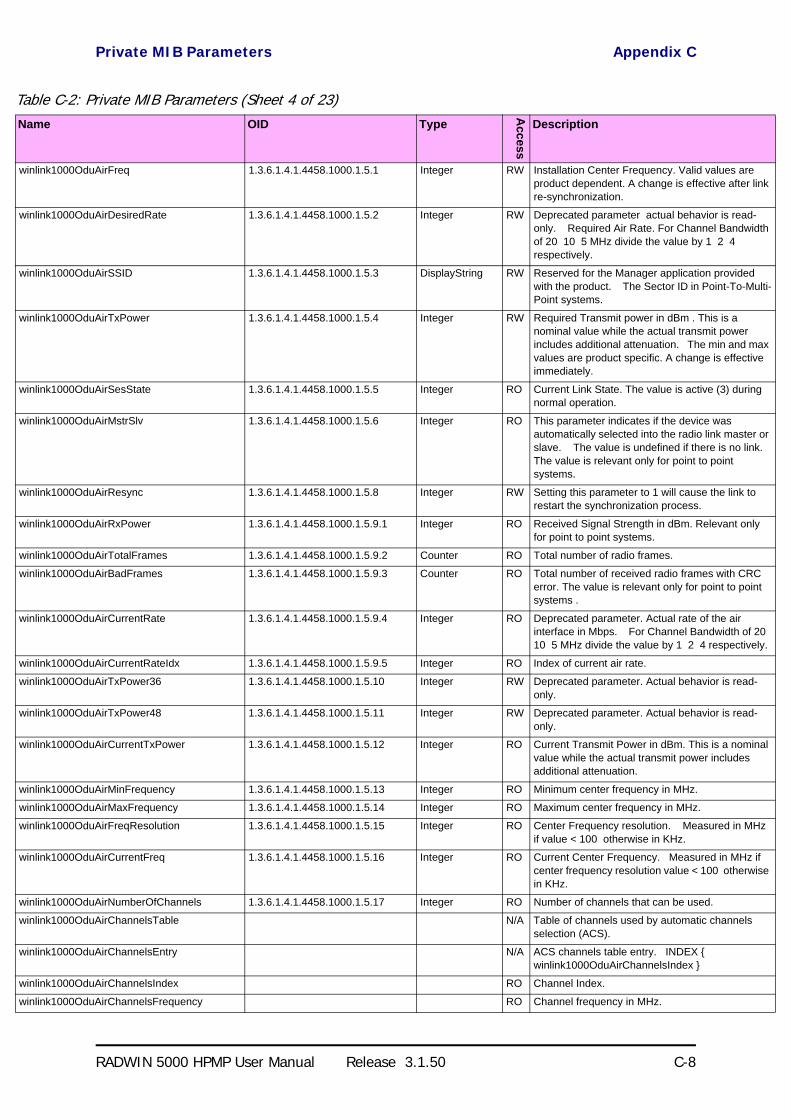
Private MIB Parameters Appendix C
RADWIN 5000 HPMP User Manual Release 3.1.50 C-8
winlink1000OduAirFreq 1.3.6.1.4.1.4458.1000.1.5.1 Integer RW Installation Center Frequency. Valid values are product dependent. A change is effective after link re-synchronization.
winlink1000OduAirDesiredRate 1.3.6.1.4.1.4458.1000.1.5.2 Integer RW Deprecated parameter actual behavior is read-only. Required Air Rate. For Channel Bandwidth of 20 10 5 MHz divide the value by 1 2 4 respectively.
winlink1000OduAirSSID 1.3.6.1.4.1.4458.1000.1.5.3 DisplayString RW Reserved for the Manager application provided with the product. The Sector ID in Point-To-Multi-Point systems.
winlink1000OduAirTxPower 1.3.6.1.4.1.4458.1000.1.5.4 Integer RW Required Transmit power in dBm . This is a nominal value while the actual transmit power includes additional attenuation. The min and max values are product specific. A change is effective immediately.
winlink1000OduAirSesState 1.3.6.1.4.1.4458.1000.1.5.5 Integer RO Current Link State. The value is active (3) during normal operation.
winlink1000OduAirMstrSlv 1.3.6.1.4.1.4458.1000.1.5.6 Integer RO This parameter indicates if the device was automatically selected into the radio link master or slave. The value is undefined if there is no link. The value is relevant only for point to point systems.
winlink1000OduAirResync 1.3.6.1.4.1.4458.1000.1.5.8 Integer RW Setting this parameter to 1 will cause the link to restart the synchronization process.
winlink1000OduAirRxPower 1.3.6.1.4.1.4458.1000.1.5.9.1 Integer RO Received Signal Strength in dBm. Relevant only for point to point systems.
winlink1000OduAirTotalFrames 1.3.6.1.4.1.4458.1000.1.5.9.2 Counter RO Total number of radio frames.
winlink1000OduAirBadFrames 1.3.6.1.4.1.4458.1000.1.5.9.3 Counter RO Total number of received radio frames with CRC error. The value is relevant only for point to point systems .
winlink1000OduAirCurrentRate 1.3.6.1.4.1.4458.1000.1.5.9.4 Integer RO Deprecated parameter. Actual rate of the air interface in Mbps. For Channel Bandwidth of 20 10 5 MHz divide the value by 1 2 4 respectively.
winlink1000OduAirCurrentRateIdx 1.3.6.1.4.1.4458.1000.1.5.9.5 Integer RO Index of current air rate.
winlink1000OduAirTxPower36 1.3.6.1.4.1.4458.1000.1.5.10 Integer RW Deprecated parameter. Actual behavior is read-only.
winlink1000OduAirTxPower48 1.3.6.1.4.1.4458.1000.1.5.11 Integer RW Deprecated parameter. Actual behavior is read-only.
winlink1000OduAirCurrentTxPower 1.3.6.1.4.1.4458.1000.1.5.12 Integer RO Current Transmit Power in dBm. This is a nominal value while the actual transmit power includes additional attenuation.
winlink1000OduAirMinFrequency 1.3.6.1.4.1.4458.1000.1.5.13 Integer RO Minimum center frequency in MHz.
winlink1000OduAirMaxFrequency 1.3.6.1.4.1.4458.1000.1.5.14 Integer RO Maximum center frequency in MHz.
winlink1000OduAirFreqResolution 1.3.6.1.4.1.4458.1000.1.5.15 Integer RO Center Frequency resolution. Measured in MHz if value < 100 otherwise in KHz.
winlink1000OduAirCurrentFreq 1.3.6.1.4.1.4458.1000.1.5.16 Integer RO Current Center Frequency. Measured in MHz if center frequency resolution value < 100 otherwise in KHz.
winlink1000OduAirNumberOfChannels 1.3.6.1.4.1.4458.1000.1.5.17 Integer RO Number of channels that can be used.
winlink1000OduAirChannelsTable N/A Table of channels used by automatic channels selection (ACS).
winlink1000OduAirChannelsEntry N/A ACS channels table entry. INDEX winlink1000OduAirChannelsIndex
winlink1000OduAirChannelsIndex RO Channel Index.
winlink1000OduAirChannelsFrequency RO Channel frequency in MHz.
Table C-2: Private MIB Parameters (Sheet 4 of 23)Name OID Type
Acc
ess
Description
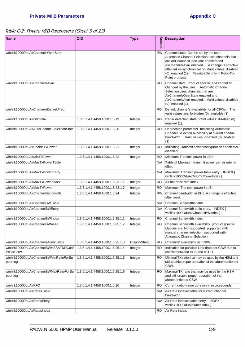
Private MIB Parameters Appendix C
RADWIN 5000 HPMP User Manual Release 3.1.50 C-9
winlink1000OduAirChannelsOperState RW Channel state. Can be set by the user. Automatic Channel Selection uses channels that are AirChannelsOperState enabled and AirChannelsAvail enabled. A change is effective after link re-synchronization. Valid values: disabled (0) enabled (1). Rewriteable only in Point-To-Point products.
winlink1000OduAirChannelsAvail RO Channel state. Product specific and cannot be changed by the user. Automatic Channel Selection uses channels that are AirChannelsOperState enabled and AirChannelsAvail enabled. Valid values: disabled (0) enabled (1).
winlink1000OduAirChannelsDefaultFreq RO Default channel's availability for all CBWs. The valid values are: forbidden (0) available (1).
winlink1000OduAirDfsState 1.3.6.1.4.1.4458.1000.1.5.19 Integer RO Radar detection state. Valid values: disabled (0) enabled (1).
winlink1000OduAirAutoChannelSelectionState 1.3.6.1.4.1.4458.1000.1.5.20 Integer RO Deprecated parameter. Indicating Automatic Channel Selection availability at current channel bandwidth. Valid values: disabled (0) enabled (1).
winlink1000OduAirEnableTxPower 1.3.6.1.4.1.4458.1000.1.5.21 Integer RO Indicating Transmit power configuration enabled or disabled.
winlink1000OduAirMinTxPower 1.3.6.1.4.1.4458.1000.1.5.22 Integer RO Minimum Transmit power in dBm.
winlink1000OduAirMaxTxPowerTable N/A Table of Maximum transmit power per air rate in dBm.
winlink1000OduAirMaxTxPowerEntry N/A Maximum Transmit power table entry. INDEX winlink1000OduAirMaxTxPowerIndex
winlink1000OduAirMaxTxPowerIndex 1.3.6.1.4.1.4458.1000.1.5.23.1.1 Integer RO Air interface rate index.
winlink1000OduAirMaxTxPower 1.3.6.1.4.1.4458.1000.1.5.23.1.2 Integer RO Maximum Transmit power in dBm.
winlink1000OduAirChannelBandwidth 1.3.6.1.4.1.4458.1000.1.5.24 Integer RW Channel bandwidth in KHz. A change is effective after reset.
winlink1000OduAirChannelBWTable N/A Channel Bandwidths table.
winlink1000OduAirChannelBWEntry N/A Channel Bandwidth table entry. INDEX winlink1000OduAirChannelBWIndex
winlink1000OduAirChannelBWIndex 1.3.6.1.4.1.4458.1000.1.5.25.1.1 Integer RO Channel Bandwidth index.
winlink1000OduAirChannelBWAvail 1.3.6.1.4.1.4458.1000.1.5.25.1.2 Integer RO Channel Bandwidth availability product specific. Options are: Not supported supported with manual channel selection supported with Automatic Channel Selection.
winlink1000OduAirChannelsAdminState 1.3.6.1.4.1.4458.1000.1.5.25.1.3 DisplayString RO Channels' availability per CBW.
winlink1000OduAirChannelBWHSSATDDConflictPerCBW
1.3.6.1.4.1.4458.1000.1.5.25.1.4 Integer RO Indication for possible Link drop per CBW due to conflict between HSS and ATDD.
winlink1000OduAirChannelBWMinRatioForSupporting
1.3.6.1.4.1.4458.1000.1.5.25.1.5 Integer RO Minimal TX ratio that may be used by the HSM and still enable proper operation of the aforementioned CBW.
winlink1000OduAirChannelBWMaxRatioForSupporting
1.3.6.1.4.1.4458.1000.1.5.25.1.6 Integer RO Maximal TX ratio that may be used by the HSM and still enable proper operation of the aforementioned CBW.
winlink1000OduAirRFD 1.3.6.1.4.1.4458.1000.1.5.26 Integer RO Current radio frame duration in microseconds.
winlink1000OduAirRatesTable N/A Air Rate indexes table for current channel bandwidth.
winlink1000OduAirRatesEntry N/A Air Rate indexes table entry. INDEX winlink1000OduAirRatesIndex
winlink1000OduAirRatesIndex RO Air Rate index.
Table C-2: Private MIB Parameters (Sheet 5 of 23)Name OID Type
Acc
ess
Description
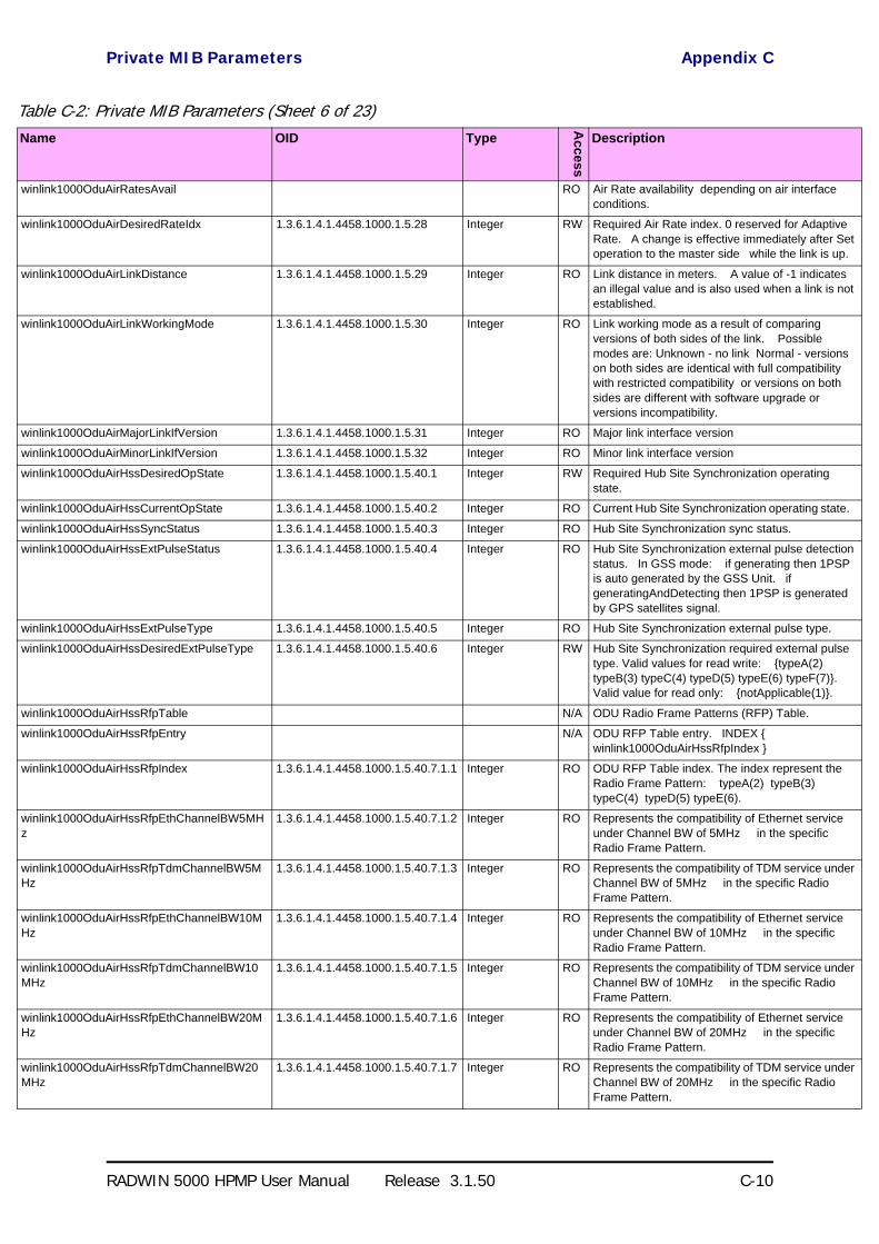
Private MIB Parameters Appendix C
RADWIN 5000 HPMP User Manual Release 3.1.50 C-10
winlink1000OduAirRatesAvail RO Air Rate availability depending on air interface conditions.
winlink1000OduAirDesiredRateIdx 1.3.6.1.4.1.4458.1000.1.5.28 Integer RW Required Air Rate index. 0 reserved for Adaptive Rate. A change is effective immediately after Set operation to the master side while the link is up.
winlink1000OduAirLinkDistance 1.3.6.1.4.1.4458.1000.1.5.29 Integer RO Link distance in meters. A value of -1 indicates an illegal value and is also used when a link is not established.
winlink1000OduAirLinkWorkingMode 1.3.6.1.4.1.4458.1000.1.5.30 Integer RO Link working mode as a result of comparing versions of both sides of the link. Possible modes are: Unknown - no link Normal - versions on both sides are identical with full compatibility with restricted compatibility or versions on both sides are different with software upgrade or versions incompatibility.
winlink1000OduAirMajorLinkIfVersion 1.3.6.1.4.1.4458.1000.1.5.31 Integer RO Major link interface version
winlink1000OduAirMinorLinkIfVersion 1.3.6.1.4.1.4458.1000.1.5.32 Integer RO Minor link interface version
winlink1000OduAirHssDesiredOpState 1.3.6.1.4.1.4458.1000.1.5.40.1 Integer RW Required Hub Site Synchronization operating state.
winlink1000OduAirHssCurrentOpState 1.3.6.1.4.1.4458.1000.1.5.40.2 Integer RO Current Hub Site Synchronization operating state.
winlink1000OduAirHssSyncStatus 1.3.6.1.4.1.4458.1000.1.5.40.3 Integer RO Hub Site Synchronization sync status.
winlink1000OduAirHssExtPulseStatus 1.3.6.1.4.1.4458.1000.1.5.40.4 Integer RO Hub Site Synchronization external pulse detection status. In GSS mode: if generating then 1PSP is auto generated by the GSS Unit. if generatingAndDetecting then 1PSP is generated by GPS satellites signal.
winlink1000OduAirHssExtPulseType 1.3.6.1.4.1.4458.1000.1.5.40.5 Integer RO Hub Site Synchronization external pulse type.
winlink1000OduAirHssDesiredExtPulseType 1.3.6.1.4.1.4458.1000.1.5.40.6 Integer RW Hub Site Synchronization required external pulse type. Valid values for read write: typeA(2) typeB(3) typeC(4) typeD(5) typeE(6) typeF(7). Valid value for read only: notApplicable(1).
winlink1000OduAirHssRfpTable N/A ODU Radio Frame Patterns (RFP) Table.
winlink1000OduAirHssRfpEntry N/A ODU RFP Table entry. INDEX winlink1000OduAirHssRfpIndex
winlink1000OduAirHssRfpIndex 1.3.6.1.4.1.4458.1000.1.5.40.7.1.1 Integer RO ODU RFP Table index. The index represent the Radio Frame Pattern: typeA(2) typeB(3) typeC(4) typeD(5) typeE(6).
winlink1000OduAirHssRfpEthChannelBW5MHz
1.3.6.1.4.1.4458.1000.1.5.40.7.1.2 Integer RO Represents the compatibility of Ethernet service under Channel BW of 5MHz in the specific Radio Frame Pattern.
winlink1000OduAirHssRfpTdmChannelBW5MHz
1.3.6.1.4.1.4458.1000.1.5.40.7.1.3 Integer RO Represents the compatibility of TDM service under Channel BW of 5MHz in the specific Radio Frame Pattern.
winlink1000OduAirHssRfpEthChannelBW10MHz
1.3.6.1.4.1.4458.1000.1.5.40.7.1.4 Integer RO Represents the compatibility of Ethernet service under Channel BW of 10MHz in the specific Radio Frame Pattern.
winlink1000OduAirHssRfpTdmChannelBW10MHz
1.3.6.1.4.1.4458.1000.1.5.40.7.1.5 Integer RO Represents the compatibility of TDM service under Channel BW of 10MHz in the specific Radio Frame Pattern.
winlink1000OduAirHssRfpEthChannelBW20MHz
1.3.6.1.4.1.4458.1000.1.5.40.7.1.6 Integer RO Represents the compatibility of Ethernet service under Channel BW of 20MHz in the specific Radio Frame Pattern.
winlink1000OduAirHssRfpTdmChannelBW20MHz
1.3.6.1.4.1.4458.1000.1.5.40.7.1.7 Integer RO Represents the compatibility of TDM service under Channel BW of 20MHz in the specific Radio Frame Pattern.
Table C-2: Private MIB Parameters (Sheet 6 of 23)Name OID Type
Acc
ess
Description
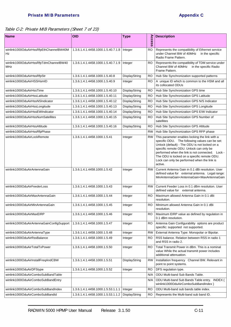
Private MIB Parameters Appendix C
RADWIN 5000 HPMP User Manual Release 3.1.50 C-11
winlink1000OduAirHssRfpEthChannelBW40MHz
1.3.6.1.4.1.4458.1000.1.5.40.7.1.8 Integer RO Represents the compatibility of Ethernet service under Channel BW of 40MHz in the specific Radio Frame Pattern.
winlink1000OduAirHssRfpTdmChannelBW40MHz
1.3.6.1.4.1.4458.1000.1.5.40.7.1.9 Integer RO Represents the compatibility of TDM service under Channel BW of 40MHz in the specific Radio Frame Pattern.
winlink1000OduAirHssRfpStr 1.3.6.1.4.1.4458.1000.1.5.40.8 DisplayString RO Hub Site Synchronization supported patterns
winlink1000OduAirHSSHsmID 1.3.6.1.4.1.4458.1000.1.5.40.9 Integer RO A unique ID which is common to the HSM and all its collocated ODUs
winlink1000OduAirHssTime 1.3.6.1.4.1.4458.1000.1.5.40.10 DisplayString RO Hub Site Synchronization GPS time
winlink1000OduAirHssLatitude 1.3.6.1.4.1.4458.1000.1.5.40.11 DisplayString RO Hub Site Synchronization GPS Latitude
winlink1000OduAirHssNSIndicator 1.3.6.1.4.1.4458.1000.1.5.40.12 DisplayString RO Hub Site Synchronization GPS N/S Indicator
winlink1000OduAirHssLongitude 1.3.6.1.4.1.4458.1000.1.5.40.13 DisplayString RO Hub Site Synchronization GPS Longitude
winlink1000OduAirHssEWIndicator 1.3.6.1.4.1.4458.1000.1.5.40.14 DisplayString RO Hub Site Synchronization GPS E/W Indicator
winlink1000OduAirHssNumSatellites 1.3.6.1.4.1.4458.1000.1.5.40.15 DisplayString RO Hub Site Synchronization GPS Number of satellites
winlink1000OduAirHssAltitude 1.3.6.1.4.1.4458.1000.1.5.40.16 DisplayString RO Hub Site Synchronization GPS Altitude
winlink1000OduAirHssRfpPhase RW Hub Site Synchronization GPS RFP phase
winlink1000OduAirLockRemote 1.3.6.1.4.1.4458.1000.1.5.41 Integer RW This parameter enables locking the link with a specific ODU. The following values can be set: Unlock (default) - The ODU is not locked on a specific remote ODU. Unlock can only be performed when the link is not connected. Lock - The ODU is locked on a specific remote ODU. Lock can only be performed when the link is active.
winlink1000OduAirAntennaGain 1.3.6.1.4.1.4458.1000.1.5.42 Integer RW Current Antenna Gain in 0.1 dBi resolution. User defined value for external antenna. Legal range: MinAntennaGain<AntennaGain<MaxAntennaGain.
winlink1000OduAirFeederLoss 1.3.6.1.4.1.4458.1000.1.5.43 Integer RW Current Feeder Loss in 0.1 dBm resolution. User defined value for external antenna.
winlink1000OduAirMaxAntennaGain 1.3.6.1.4.1.4458.1000.1.5.44 Integer RO Maximum allowed Antenna Gain in 0.1 dBi resolution.
winlink1000OduAirMinAntennaGain 1.3.6.1.4.1.4458.1000.1.5.45 Integer RO Minimum allowed Antenna Gain in 0.1 dBi resolution.
winlink1000OduAirMaxEIRP 1.3.6.1.4.1.4458.1000.1.5.46 Integer RO Maximum EIRP value as defined by regulation in 0.1 dBm resolution.
winlink1000OduAirAntennaGainConfigSupport 1.3.6.1.4.1.4458.1000.1.5.47 Integer RO Antenna Gain Configurability options are product specific: supported not supported.
winlink1000OduAirAntennaType 1.3.6.1.4.1.4458.1000.1.5.48 Integer RW External Antenna Type: Monopolar or Bipolar.
winlink1000OduAirRssBalance 1.3.6.1.4.1.4458.1000.1.5.49 Integer RO RSS balance. Relation between RSS in radio 1 and RSS in radio 2.
winlink1000OduAirTotalTxPower 1.3.6.1.4.1.4458.1000.1.5.50 Integer RO Total Transmit Power in dBm. This is a nominal value While the actual transmit power includes additional attenuation.
winlink1000OduAirInstallFreqAndCBW 1.3.6.1.4.1.4458.1000.1.5.51 DisplayString RW Installation frequency Channel BW. Relevant in point to point systems.
winlink1000OduAirDFStype 1.3.6.1.4.1.4458.1000.1.5.52 Integer RO DFS regulation type.
winlink1000OduAirComboSubBandTable N/A ODU Multi-band Sub Bands Table.
winlink1000OduAirComboSubBandEntry N/A ODU Multi-band Sub Bands Table entry. INDEX winlink1000OduAirComboSubBandIndex
winlink1000OduAirComboSubBandIndex 1.3.6.1.4.1.4458.1000.1.5.53.1.1.1 Integer RO ODU Multi-band sub bands table index.
winlink1000OduAirComboSubBandId 1.3.6.1.4.1.4458.1000.1.5.53.1.1.2 DisplayString RO Represents the Multi-band sub band ID.
Table C-2: Private MIB Parameters (Sheet 7 of 23)Name OID Type
Acc
ess
Description
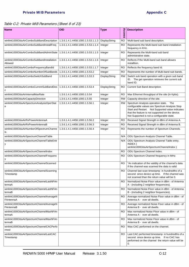
Private MIB Parameters Appendix C
RADWIN 5000 HPMP User Manual Release 3.1.50 C-12
winlink1000OduAirComboSubBandDescription 1.3.6.1.4.1.4458.1000.1.5.53.1.1.3 DisplayString RO Multi-band sub band description.
winlink1000OduAirComboSubBandInstallFreq 1.3.6.1.4.1.4458.1000.1.5.53.1.1.4 Integer RO Represents the Multi-band sub band installation frequency in KHz.
winlink1000OduAirComboSubBandAdminState 1.3.6.1.4.1.4458.1000.1.5.53.1.1.5 Integer RO Represents the Multi-band sub band administrative state.
winlink1000OduAirComboSubBandInstallationAllowed
1.3.6.1.4.1.4458.1000.1.5.53.1.1.6 Integer RO Reflects if the Multi-band sub band allowes installtion.
winlink1000OduAirComboFrequencyBandId 1.3.6.1.4.1.4458.1000.1.5.53.1.1.7 Integer RO Reflects the frequency band Id.
winlink1000OduAirComboNumberOfSubBands 1.3.6.1.4.1.4458.1000.1.5.53.2 Integer RO Represents the number of Multi-band sub bands.
winlink1000OduAirComboSwitchSubBand 1.3.6.1.4.1.4458.1000.1.5.53.3 DisplayString RW Switch sub band operation with a given sub band ID. The get operation retrieves the current sub band ID.
winlink1000OduAirComboCurrentSubBandDesc
1.3.6.1.4.1.4458.1000.1.5.53.4 DisplayString RO Current Sub Band description.
winlink1000OduAirInternalMaxRate 1.3.6.1.4.1.4458.1000.1.5.54 Integer RO Max Ethernet throughput of the site (in Kpbs).
winlink1000OduAirCapacityDirection 1.3.6.1.4.1.4458.1000.1.5.55 Integer RW Capacity direction of the site.
winlink1000OduAirSpectrumAnalysisOperState
1.3.6.1.4.1.4458.1000.1.5.56.1 Integer RW Spectrum Analysis operation state. The configurable values are Spectrum Analysis Stop Start and Restart. Not Supported value indicates that the feature is not supported on the device. Not Supported is not a configurable state.
winlink1000OduAirRxPowerAntennaA 1.3.6.1.4.1.4458.1000.1.5.56.2 Integer RO Received Signal Strength in dBm of Antenna A.
winlink1000OduAirRxPowerAntennaB 1.3.6.1.4.1.4458.1000.1.5.56.3 Integer RO Received Signal Strength in dBm of Antenna B.
winlink1000OduAirNumberOfSpectrumChannels
1.3.6.1.4.1.4458.1000.1.5.56.4 Integer RO Represents the number of Spectrum Channels.
winlink1000OduAirSpectrumChannelTable N/A ODU Spectrum Analysis Channel Table.
winlink1000OduAirSpectrumChannelTableEntry
N/A ODU Spectrum Analysis Channel Table entry. INDEX winlink1000OduAirSpectrumChannelIndex
winlink1000OduAirSpectrumChannelIndex RO ODU Spectrum Channel index.
winlink1000OduAirSpectrumChannelFrequency
RO ODU Spectrum Channel frequency in MHz.
winlink1000OduAirSpectrumChannelScanned RO "An indication of the vaildity of the channel's data. If the channel was scanned the data is valid
winlink1000OduAirSpectrumChannelScanningTimestamp
RO Channel last scan timestamp in hundredths of a second since device up time. If the channel was not scanned than the return value will be 0.
winlink1000OduAirSpectrumChannelLastNFAntennaA
RO Normalized Noise Floor value in dBm - of Antenna A - (including 2 neighbor frequencies).
winlink1000OduAirSpectrumChannelLastNFAntennaB
RO Normalized Noise Floor value in dBm - of Antenna B - (including 2 neighbor frequencies).
winlink1000OduAirSpectrumChannelAverageNFAntennaA
RO Average normalized Noise Floor value in dBm - of Antenna A - over all dwells.
winlink1000OduAirSpectrumChannelAverageNFAntennaB
RO Average normalized Noise Floor value in dBm - of Antenna B - over all dwells.
winlink1000OduAirSpectrumChannelMaxNFAntennaA
RO Max normalized Noise Floor value in dBm - of Antenna A - over all dwells.
winlink1000OduAirSpectrumChannelMaxNFAntennaB
RO Max normalized Noise Floor value in dBm - of Antenna B - over all dwells.
winlink1000OduAirSpectrumChannelCACPerformed
RO Was CAC performed on the channel.
winlink1000OduAirSpectrumChannelLastCACTimestamp
RO Last CAC performed timestamp in hundredths of a second since device up time. If no CAC has performed on the channel the return value will be 0.
Table C-2: Private MIB Parameters (Sheet 8 of 23)Name OID Type
Acc
ess
Description
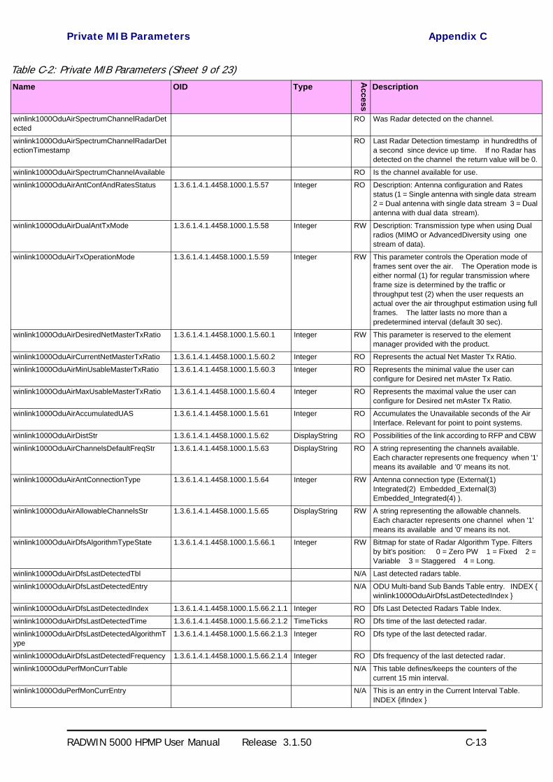
Private MIB Parameters Appendix C
RADWIN 5000 HPMP User Manual Release 3.1.50 C-13
winlink1000OduAirSpectrumChannelRadarDetected
RO Was Radar detected on the channel.
winlink1000OduAirSpectrumChannelRadarDetectionTimestamp
RO Last Radar Detection timestamp in hundredths of a second since device up time. If no Radar has detected on the channel the return value will be 0.
winlink1000OduAirSpectrumChannelAvailable RO Is the channel available for use.
winlink1000OduAirAntConfAndRatesStatus 1.3.6.1.4.1.4458.1000.1.5.57 Integer RO Description: Antenna configuration and Rates status (1 = Single antenna with single data stream 2 = Dual antenna with single data stream 3 = Dual antenna with dual data stream).
winlink1000OduAirDualAntTxMode 1.3.6.1.4.1.4458.1000.1.5.58 Integer RW Description: Transmission type when using Dual radios (MIMO or AdvancedDiversity using one stream of data).
winlink1000OduAirTxOperationMode 1.3.6.1.4.1.4458.1000.1.5.59 Integer RW This parameter controls the Operation mode of frames sent over the air. The Operation mode is either normal (1) for regular transmission where frame size is determined by the traffic or throughput test (2) when the user requests an actual over the air throughput estimation using full frames. The latter lasts no more than a predetermined interval (default 30 sec).
winlink1000OduAirDesiredNetMasterTxRatio 1.3.6.1.4.1.4458.1000.1.5.60.1 Integer RW This parameter is reserved to the element manager provided with the product.
winlink1000OduAirCurrentNetMasterTxRatio 1.3.6.1.4.1.4458.1000.1.5.60.2 Integer RO Represents the actual Net Master Tx RAtio.
winlink1000OduAirMinUsableMasterTxRatio 1.3.6.1.4.1.4458.1000.1.5.60.3 Integer RO Represents the minimal value the user can configure for Desired net mAster Tx Ratio.
winlink1000OduAirMaxUsableMasterTxRatio 1.3.6.1.4.1.4458.1000.1.5.60.4 Integer RO Represents the maximal value the user can configure for Desired net mAster Tx Ratio.
winlink1000OduAirAccumulatedUAS 1.3.6.1.4.1.4458.1000.1.5.61 Integer RO Accumulates the Unavailable seconds of the Air Interface. Relevant for point to point systems.
winlink1000OduAirDistStr 1.3.6.1.4.1.4458.1000.1.5.62 DisplayString RO Possibilities of the link according to RFP and CBW
winlink1000OduAirChannelsDefaultFreqStr 1.3.6.1.4.1.4458.1000.1.5.63 DisplayString RO A string representing the channels available. Each character represents one frequency when '1' means its available and '0' means its not.
winlink1000OduAirAntConnectionType 1.3.6.1.4.1.4458.1000.1.5.64 Integer RW Antenna connection type (External(1) Integrated(2) Embedded_External(3) Embedded_Integrated(4) ).
winlink1000OduAirAllowableChannelsStr 1.3.6.1.4.1.4458.1000.1.5.65 DisplayString RW A string representing the allowable channels. Each character represents one channel when '1' means its available and '0' means its not.
winlink1000OduAirDfsAlgorithmTypeState 1.3.6.1.4.1.4458.1000.1.5.66.1 Integer RW Bitmap for state of Radar Algorithm Type. Filters by bit's position: 0 = Zero PW 1 = Fixed 2 = Variable 3 = Staggered 4 = Long.
winlink1000OduAirDfsLastDetectedTbl N/A Last detected radars table.
winlink1000OduAirDfsLastDetectedEntry N/A ODU Multi-band Sub Bands Table entry. INDEX winlink1000OduAirDfsLastDetectedIndex
winlink1000OduAirDfsLastDetectedIndex 1.3.6.1.4.1.4458.1000.1.5.66.2.1.1 Integer RO Dfs Last Detected Radars Table Index.
winlink1000OduAirDfsLastDetectedTime 1.3.6.1.4.1.4458.1000.1.5.66.2.1.2 TimeTicks RO Dfs time of the last detected radar.
winlink1000OduAirDfsLastDetectedAlgorithmType
1.3.6.1.4.1.4458.1000.1.5.66.2.1.3 Integer RO Dfs type of the last detected radar.
winlink1000OduAirDfsLastDetectedFrequency 1.3.6.1.4.1.4458.1000.1.5.66.2.1.4 Integer RO Dfs frequency of the last detected radar.
winlink1000OduPerfMonCurrTable N/A This table defines/keeps the counters of the current 15 min interval.
winlink1000OduPerfMonCurrEntry N/A This is an entry in the Current Interval Table. INDEX ifIndex
Table C-2: Private MIB Parameters (Sheet 9 of 23)Name OID Type
Acc
ess
Description

Private MIB Parameters Appendix C
RADWIN 5000 HPMP User Manual Release 3.1.50 C-14
winlink1000OduPerfMonCurrUAS 1.3.6.1.4.1.4458.1000.1.6.1.1.1 Gauge RO The current number of Unavailable Seconds starting from the present 15 minutes period.
winlink1000OduPerfMonCurrES 1.3.6.1.4.1.4458.1000.1.6.1.1.2 Gauge RO Current number of Errored Seconds starting from the present 15 minutes period.
winlink1000OduPerfMonCurrSES 1.3.6.1.4.1.4458.1000.1.6.1.1.3 Gauge RO Current number of Severely Errored Seconds starting from the present 15 minutes period.
winlink1000OduPerfMonCurrBBE 1.3.6.1.4.1.4458.1000.1.6.1.1.4 Gauge RO Current number of Background Block Errors starting from the present 15 minutes period.
winlink1000OduPerfMonCurrIntegrity 1.3.6.1.4.1.4458.1000.1.6.1.1.5 Integer RO Indicates the integrity of the entry.
winlink1000OduPerfMonCurrCompressed 1.3.6.1.4.1.4458.1000.1.6.1.1.6 OctetString RO Holds a compressed string of all data per interface. Compressed Air Interface Structure (size in brackets): UAS (4) ES (4) SES (4) BBE (4) Integrity (1) MinRSL (1) MaxRSL (1) RSLThresh1Exceeded (4) RSLThresh2Exceeded (4) MinTSL (1) MaxTSL (1) TSLThresh1Exceed (4) BBERThresh1Exceed (4) RxMBytes (4) TxMBytes (4) EthCapacityThreshUnder (4) HighTrafficThreshExceed (4) Compressed Etherent ODU interface (size in brackets): UAS (4) ES (4) SES (4) BBE (4) Integrity (1) RxMBytes (4) TxMBytes (4) EthCapacityThreshUnder (4) HighTrafficThreshExceed (4) ActiveSeconds (4)
winlink1000OduPerfMonIntervalTable N/A This table defines/keeps the counters of the last day (in resolution of 15 min intervals).
winlink1000OduPerfMonIntervalEntry N/A This is an entry in the Interval Table. INDEX ifIndex winlink1000OduPerfMonIntervalIdx
winlink1000OduPerfMonIntervalIdx RO This table is indexed per interval number. Each interval is of 15 minutes and the oldest is 96.
winlink1000OduPerfMonIntervalUAS RO The current number of Unavailable Seconds per interval.
winlink1000OduPerfMonIntervalES RO Current number of Errored Seconds per interval.
winlink1000OduPerfMonIntervalSES RO Current number of Severely Errored Seconds per interval.
winlink1000OduPerfMonIntervalBBE RO Current number of Background Block Errors per interval.
winlink1000OduPerfMonIntervalIntegrity RO Indicates the integrity of the entry per interval.
winlink1000OduPerfMonIntervalCompressed RO Holds a compressed string of all data per interface. Compressed Air Interface Structure (size in brackets): UAS (4) ES (4) SES (4) BBE (4) Integrity (1) MinRSL (1) MaxRSL (1) RSLThresh1Exceeded (4) RSLThresh2Exceeded (4) MinTSL (1) MaxTSL (1) TSLThresh1Exceed (4) BBERThresh1Exceed (4) RxMBytes (4) TxMBytes (4) EthCapacityThreshUnder (4) HighTrafficThreshExceed (4) Compressed Etherent ODU interface (size in brackets): UAS (4) ES (4) SES (4) BBE (4) Integrity (1) RxMBytes (4) TxMBytes (4) EthCapacityThreshUnder (4) HighTrafficThreshExceed (4) ActiveSeconds (1)
winlink1000OduPerfMonDayTable N/A This table defines/keeps the counters of the last month (in resolution of days).
winlink1000OduPerfMonDayEntry N/A This is an entry in the Days Table. INDEX ifIndex winlink1000OduPerfMonDayIdx
Table C-2: Private MIB Parameters (Sheet 10 of 23)Name OID Type
Acc
ess
Description

Private MIB Parameters Appendix C
RADWIN 5000 HPMP User Manual Release 3.1.50 C-15
winlink1000OduPerfMonDayIdx RO This table is indexed per interval number. Each interval is of 24 hours and the oldest is 30.
winlink1000OduPerfMonDayUAS RO The current number of Unavailable Seconds per interval of 24 hours.
winlink1000OduPerfMonDayES RO Current number of Errored Seconds per interval of 24 hours.
winlink1000OduPerfMonDaySES RO Current number of Severely Errored Seconds per interval of 24 hours.
winlink1000OduPerfMonDayBBE RO Current number of Background Block Errors per interval of 24 hours.
winlink1000OduPerfMonDayIntegrity RO Indicates the integrity of the entry per interval of 24 hours.
winlink1000OduPerfMonDayCompressed RO Holds a compressed string of all data per interface. Compressed Air Interface Structure (size in brackets): UAS (4) ES (4) SES (4) BBE (4) Integrity (1) MinRSL (1) MaxRSL (1) RSLThresh1Exceeded (4) RSLThresh2Exceeded (4) MinTSL (1) MaxTSL (1) TSLThresh1Exceed (4) BBERThresh1Exceed (4) RxMBytes (4) TxMBytes (4) EthCapacityThreshUnder (4) HighTrafficThreshExceed (4) Compressed Etherent ODU interface (size in brackets): UAS (4) ES (4) SES (4) BBE (4) Integrity (1) RxMBytes (4) TxMBytes (4) EthCapacityThreshUnder (4) HighTrafficThreshExceed (4) ActiveSeconds (1)
winlink1000OduPerfMonAirCurrTable N/A This table defines/keeps the air counters of the current 15 min interval.
winlink1000OduPerfMonAirCurrEntry N/A This is an entry in the Current Interval Table. INDEX ifIndex
winlink1000OduPerfMonAirCurrMinRSL 1.3.6.1.4.1.4458.1000.1.6.4.1.1 Integer RO Current Min Received Level Reference starting from the present 15 minutes period.
winlink1000OduPerfMonAirCurrMaxRSL 1.3.6.1.4.1.4458.1000.1.6.4.1.2 Integer RO Current Max Received Level Reference starting from the present 15 minutes period.
winlink1000OduPerfMonAirCurrRSLThresh1Exceed
1.3.6.1.4.1.4458.1000.1.6.4.1.3 Gauge RO Number of seconds Receive Signal Level exceeded the RSL1 threshold in the last 15 minutes.
winlink1000OduPerfMonAirCurrRSLThresh2Exceed
1.3.6.1.4.1.4458.1000.1.6.4.1.4 Gauge RO Number of seconds Receive Signal Level exceeded the RSL2 threshold in the last 15 minutes.
winlink1000OduPerfMonAirCurrMinTSL 1.3.6.1.4.1.4458.1000.1.6.4.1.5 Integer RO Current Min Transmit Signal Level starting from the present 15 minutes period.
winlink1000OduPerfMonAirCurrMaxTSL 1.3.6.1.4.1.4458.1000.1.6.4.1.6 Integer RO Current Max Transmit Signal Level starting from the present 15 minutes period.
winlink1000OduPerfMonAirCurrTSLThresh1Exceed
1.3.6.1.4.1.4458.1000.1.6.4.1.7 Gauge RO Number of seconds Transmit Signal Level exceeded the TSL1 threshold in the last 15 minutes.
winlink1000OduPerfMonAirCurrBBERThresh1Exceed
1.3.6.1.4.1.4458.1000.1.6.4.1.8 Gauge RO Number of seconds Background Block Error Ratio exceeded the BBER1 threshold in the last 15 minutes.
winlink1000OduPerfMonAirIntervalTable N/A This table defines/keeps the air counters of the last day (in resolution of 15 min intervals).
winlink1000OduPerfMonAirIntervalEntry N/A This is an entry in the Interval Table. INDEX ifIndex winlink1000OduPerfMonAirIntervalIdx
winlink1000OduPerfMonAirIntervalIdx RO This table is indexed per interval number. Each interval is of 15 minutes and the oldest is 96.
Table C-2: Private MIB Parameters (Sheet 11 of 23)Name OID Type
Acc
ess
Description

Private MIB Parameters Appendix C
RADWIN 5000 HPMP User Manual Release 3.1.50 C-16
winlink1000OduPerfMonAirIntervalMinRSL RO Current Min Received Level Reference per interval.
winlink1000OduPerfMonAirIntervalMaxRSL RO Current Max Received Level Reference per interval.
winlink1000OduPerfMonAirIntervalRSLThresh1Exceed
RO Number of seconds Receive Signal Level exceeded the RSL1 threshold per interval.
winlink1000OduPerfMonAirIntervalRSLThresh2Exceed
RO Number of seconds Receive Signal Level exceeded the RSL2 threshold per interval.
winlink1000OduPerfMonAirIntervalMinTSL RO Current Min Transmit Signal Level per interval.
winlink1000OduPerfMonAirIntervalMaxTSL RO Current Max Transmit Signal Level per interval.
winlink1000OduPerfMonAirIntervalTSLThresh1Exceed
RO Number of seconds Transmit Signal Level exceeded the TSL1 threshold per interval.
winlink1000OduPerfMonAirIntervalBBERThresh1Exceed
RO Number of seconds Background Block Error Ratio exceeded the BBER1 threshold per interval.
winlink1000OduPerfMonAirDayTable N/A This table defines/keeps the air counters of the last month (in resolution of days).
winlink1000OduPerfMonAirDayEntry N/A This is an entry in the Days Table. INDEX ifIndex winlink1000OduPerfMonAirDayIdx
winlink1000OduPerfMonAirDayIdx RO This table is indexed per Day number. Each Day is of 15 minutes and the oldest is 96.
winlink1000OduPerfMonAirDayMinRSL RO Current Min Received Level Reference per Day.
winlink1000OduPerfMonAirDayMaxRSL RO Current Max Received Level Reference per Day.
winlink1000OduPerfMonAirDayRSLThresh1Exceed
RO Number of seconds Receive Signal Level exceeded the RSL1 threshold per Day.
winlink1000OduPerfMonAirDayRSLThresh2Exceed
RO Number of seconds Receive Signal Level exceeded the RSL2 threshold per Day.
winlink1000OduPerfMonAirDayMinTSL RO Current Min Transmit Signal Level per Day.
winlink1000OduPerfMonAirDayMaxTSL RO Current Max Transmit Signal Level per Day.
winlink1000OduPerfMonAirDayTSLThresh1Exceed
RO Number of seconds Transmit Signal Level exceeded the TSL1 threshold per Day.
winlink1000OduPerfMonAirDayBBERThresh1Exceed
RO Number of seconds Background Block Error Ratio exceeded the BBER1 threshold per Day.
winlink1000OduPerfMonEthCurrTable N/A This table defines/keeps the ethernet counters of the current 15 min interval.
winlink1000OduPerfMonEthCurrEntry N/A This is an entry in the Current Interval Table. INDEX ifIndex
winlink1000OduPerfMonEthCurrRxMBytes 1.3.6.1.4.1.4458.1000.1.6.7.1.1 Gauge RO Current RX Mega Bytes starting from the present 15 minutes period.
winlink1000OduPerfMonEthCurrTxMBytes 1.3.6.1.4.1.4458.1000.1.6.7.1.2 Gauge RO Current Transmit Mega Bytes starting from the present 15 minutes period.
winlink1000OduPerfMonEthCurrEthCapacityThreshUnder
1.3.6.1.4.1.4458.1000.1.6.7.1.3 Gauge RO The number of times throughput was below threshold in the present 15 minutes period. Relevant for point to point systems.
winlink1000OduPerfMonEthCurrHighTrafficThreshExceed
1.3.6.1.4.1.4458.1000.1.6.7.1.4 Gauge RO The number of times actual traffic was above threshold in the present 15 minutes period.
winlink1000OduPerfMonEthCurrActiveSeconds
1.3.6.1.4.1.4458.1000.1.6.7.1.5 Gauge RO The number of seconds in which RPL Ethernet swervice was not blocked in the present 15 minutes period.
winlink1000OduPerfMonEthIntervalTable N/A This table defines/keeps the ethernet counters of the last day (in resolution of 15 min intervals).
winlink1000OduPerfMonEthIntervalEntry N/A This is an entry in the Interval Table. INDEX ifIndex winlink1000OduPerfMonEthIntervalIdx
winlink1000OduPerfMonEthIntervalIdx RO This table is indexed per interval number. Each interval is of 15 minutes and the oldest is 96.
Table C-2: Private MIB Parameters (Sheet 12 of 23)Name OID Type
Acc
ess
Description

Private MIB Parameters Appendix C
RADWIN 5000 HPMP User Manual Release 3.1.50 C-17
winlink1000OduPerfMonEthIntervalRxMBytes RO Current RX Mega Bytes per interval.
winlink1000OduPerfMonEthIntervalTxMBytes RO Current Transmit Mega Bytes per interval.
winlink1000OduPerfMonEthIntervalEthCapacityThreshUnder
RO The number of times throughput was below threshold in the each interval. Relevant for point to point systems.
winlink1000OduPerfMonEthIntervalHighTrafficThreshExceed
RO The number of times actual traffic was above threshold in the each interval.
winlink1000OduPerfMonEthIntervalActiveSeconds
RO The number of seconds in which RPL Ethernet service was not blocked in the each interval.
winlink1000OduPerfMonEthDayTable N/A This table defines/keeps the ethernet counters of the last month (in resolution of days).
winlink1000OduPerfMonEthDayEntry N/A This is an entry in the Days Table. INDEX ifIndex winlink1000OduPerfMonEthDayIdx
winlink1000OduPerfMonEthDayIdx RO This table is indexed per Day number. Each interval is of 15 minutes and the oldest is 96.
winlink1000OduPerfMonEthDayRxMBytes RO Current RX Mega Bytes per day.
winlink1000OduPerfMonEthDayTxMBytes RO Current Transmit Mega Bytes per day.
winlink1000OduPerfMonEthDayEthCapacityThreshUnder
RO The number of times throughput was below threshold each day. Relevant for point to point systems.
winlink1000OduPerfMonEthDayHighTrafficThreshExceed
RO The number of times actual traffic was above threshold each day.
winlink1000OduPerfMonEthDayActiveSeconds RO The number of seconds in which RPL Ethernet service was not blocked each day.
winlink1000OduPerfMonTdmCurrTable N/A This table defines/keeps the TDM counters of the current 15 min interval.
winlink1000OduPerfMonTdmCurrEntry N/A This is an entry in the Current Interval Table. INDEX ifIndex
winlink1000OduPerfMonTdmCurrActiveSeconds
1.3.6.1.4.1.4458.1000.1.6.10.1.1 Gauge RO Parameter indicating whether the TDM service was active. Under TDM backup link the parameter indicates whether the backup link was active.
winlink1000OduPerfMonTdmIntervalTable N/A This table defines/keeps the TDM counters of the last day (in resolution of 15 min intervals).
winlink1000OduPerfMonTdmIntervalEntry N/A This is an entry in the Interval Table. INDEX ifIndex winlink1000OduPerfMonTdmIntervalIdx
winlink1000OduPerfMonTdmIntervalIdx RO This table is indexed per interval number. Each interval is of 15 minutes and the oldest is 96.
winlink1000OduPerfMonTdmIntervalActiveSeconds
RO Parameter indicating whether the TDM service was active. Under TDM backup link the parameter indicates whether the backup link was active.
winlink1000OduPerfMonTdmDayTable N/A This table defines/keeps the TDM counters of the last month (in resolution of days).
winlink1000OduPerfMonTdmDayEntry N/A This is an entry in the Days Table. INDEX ifIndex winlink1000OduPerfMonTdmDayIdx
winlink1000OduPerfMonTdmDayIdx RO This table is indexed per Day number. Each interval is of 15 minutes and the oldest is 96.
winlink1000OduPerfMonTdmDayActiveSeconds
RO Parameter indicating whether the TDM service was active. Under TDM backup link the parameter indicates whether the backup link was active.
winlink1000OduPerfMonTxThresh1 1.3.6.1.4.1.4458.1000.1.6.20 Integer RW When the Transmit power exceeds this threshold a performance monitoring TSL1 counter is incremented.
Table C-2: Private MIB Parameters (Sheet 13 of 23)Name OID Type
Acc
ess
Description

Private MIB Parameters Appendix C
RADWIN 5000 HPMP User Manual Release 3.1.50 C-18
winlink1000OduPerfMonRxThresh1 1.3.6.1.4.1.4458.1000.1.6.21 Integer RW When the RX power exceeds this threshold a performance monitoring RSL1 counter is incremented.
winlink1000OduPerfMonRxThresh2 1.3.6.1.4.1.4458.1000.1.6.22 Integer RW When the RX power exceeds this threshold a performance monitoring RSL2 counter is incremented.
winlink1000OduPerfMonBBERThresh1 1.3.6.1.4.1.4458.1000.1.6.23 Integer RW When the BBER exceeds this threshold a performance monitoring BBER counter is incremented. The units are 1/10 of a percent.
winlink1000OduPerfMonEthCapacityThreshKbps
1.3.6.1.4.1.4458.1000.1.6.24 Integer RW When the current throughput is below this threshold the corresponding counter is incremented
winlink1000OduPerfMonHighTrafficThreshKbps
1.3.6.1.4.1.4458.1000.1.6.25 Integer RW When the current traffic is above this threshold then corresponding counter is incremented.
winlink1000OduAgnGenAddTrapExt 1.3.6.1.4.1.4458.1000.1.7.1.1 Integer RW If 'yes' is chosen the ifIndex Unit Severity Time_T and Alarm Id from the winlink1000OduAgnCurrAlarmTable will be bind to the end of each private trap.
winlink1000OduAgnGenSetMode 1.3.6.1.4.1.4458.1000.1.7.1.2 Integer RW This parameter is reserved to the element manager provided with the product.
winlink1000OduAgnNTPCfgTimeServerIP 1.3.6.1.4.1.4458.1000.1.7.2.1 IpAddress RW IP address of the server from which the current time is loaded.
winlink1000OduAgnNTPCfgTimeOffsetFromUTC
1.3.6.1.4.1.4458.1000.1.7.2.2 Integer RW Offset from Coordinated Universal Time (minutes). Possible values: -1440..1440.
winlink1000OduAgnRealTimeAndDate 1.3.6.1.4.1.4458.1000.1.7.2.3 OctetString RW This parameter specifies the real time and date Format 'YYYY-MM-DD HH:MM:SS' (Hexadecimal). A date-time specification: field octets contents range ----- ------ -------- ----- 1 1-2 year 0..65536 2 3 month 1..12 3 4 day 1..31 4 5 hour 0..23 5 6 minutes 0..59 6 7 seconds 0..60 (use 60 for leap-second) 7 8 deci-seconds 0..9 For example Tuesday May 26 1992 at 1:30:15 PM EDT would be displayed as: 07 c8 05 1a 0d 1e 0f 00 ( 1992 -5 -26 13:30:15 )
winlink1000OduAgnCurrAlarmLastChange 1.3.6.1.4.1.4458.1000.1.7.3.1 Integer RO This counter is initialized to 0 after a device reset and is incremented upon each change in the winlink1000OduAgnCurrAlarmTable (either an addition or removal of an entry).
winlink1000OduAgnCurrAlarmTable N/A This table includes the currently active alarms. When a RAISED trap is sent an alarm entry is added to the table. When a CLEAR trap is sent the entry is removed.
winlink1000OduAgnCurrAlarmEntry N/A Entry containing the details of a currently RAISED trap. INDEX winlink1000OduAgnCurrAlarmCounter
winlink1000OduAgnCurrAlarmCounter RO A running counter of active alarms. The counter is incremented for every new RAISED trap. It is cleared after a device reset.
winlink1000OduAgnCurrAlarmSeverity RO Current Alarm severity.
winlink1000OduAgnCurrAlarmId RO Unique Alarm Identifier (combines alarm type and interface). The same AlarmId is used for RAISED and CLEARED alarms.
winlink1000OduAgnCurrAlarmIfIndex RO Interface Index where the alarm occurred. Alarms that are not associated with a specific interface will have the following value: 65535.
Table C-2: Private MIB Parameters (Sheet 14 of 23)Name OID Type
Acc
ess
Description

Private MIB Parameters Appendix C
RADWIN 5000 HPMP User Manual Release 3.1.50 C-19
winlink1000OduAgnCurrAlarmUnit RO Unit associated with the alarm.
winlink1000OduAgnCurrAlarmTrapID RO ID of the raised trap that was sent when this alarm was raised.
winlink1000OduAgnCurrAlarmTimeT RO Timestamp of this alarm. This number is in seconds from Midnight January 1st 1970.
winlink1000OduAgnCurrAlarmText RO Alarm display text (same as the text in the sent trap).
winlink1000OduAgnLastEventsNumber 1.3.6.1.4.1.4458.1000.1.7.4.1 Integer RO This counter indicates the size of the winlink1000OduAgnLastEventsTable
winlink1000OduAgnLastEventsTable N/A This table includes the last events. When a trap is sent an event entry is added to the table.
winlink1000OduAgnLastEventsEntry N/A Entry containing the details of last traps. INDEX winlink1000OduAgnLastEventsIndex
winlink1000OduAgnLastEventsIndex 1.3.6.1.4.1.4458.1000.1.7.4.2.1.1 Integer RO The index of the table
winlink1000OduAgnLastEventsSeverity 1.3.6.1.4.1.4458.1000.1.7.4.2.1.2 Integer RO Current Trap severity.
winlink1000OduAgnLastEventsIfIndex 1.3.6.1.4.1.4458.1000.1.7.4.2.1.3 Integer RO Interface Index where the event occurred. Traps that are not associated with a specific interface will have the following value: 65535.
winlink1000OduAgnLastEventsTimeT 1.3.6.1.4.1.4458.1000.1.7.4.2.1.4 Integer RO Timestamp of this trap. This number is in seconds from Midnight January 1st 1970.
winlink1000OduAgnLastEventsText 1.3.6.1.4.1.4458.1000.1.7.4.2.1.5 DisplayString RO Trap display text (same as the text in the sent trap).
winlink1000IduAdmProductType RO IDU configuration description.
winlink1000IduAdmHwRev RO IDU Hardware Revision.
winlink1000IduAdmSwRev RO IDU Software Revision.
winlink1000OduAdmNumOfExternalAlarmIn RO Indicates the number of currently available External Alarm Inputs.
winlink1000OduAdmExternAlarmInTable N/A This is the External Alarm Inputs table.
winlink1000OduAdmExternAlarmInEntry N/A Entry containing the elements of a single External Alarm Input. INDEX winlink1000OduAdmExternAlarmInIndex
winlink1000OduAdmExternAlarmInIndex 1.3.6.1.4.1.4458.1000.2.1.5.1.1 Integer RO This value indicates the index of the External Alarm Input entry.
winlink1000OduAdmExternAlarmInText RW This field describes the External Alarm Input. It is an optional string of no more than 64 characters which will be used in the event being sent as a result of a change in the status of the External Alarm Input. DEFVAL Alarm Description
winlink1000OduAdmExternAlarmInAdminState 1.3.6.1.4.1.4458.1000.2.1.5.1.3 Integer RW This value indicates if this External Alarm Input is enabled or disabled.
winlink1000OduAdmExternAlarmInStatus 1.3.6.1.4.1.4458.1000.2.1.5.1.4 Integer RO This value indicates the current status of the External Alarm Input.
winlink1000IduAdmSN RO IDU Serial Number
winlink1000IduAdmIduDetectionMode RW The parameter defines whether to send Ethernet frames to detect an IDU. The valid writable values are: userDisabled (3) userEnabled (4). A change requires a reset and is effective after reset.
winlink1000IduAdmMountedTrunks RO Number of mounted trunks in the IDU
winlink1000IduAdmLicensedTrunks RO Number of Licensed Trunks in the IDU
winlink1000IduAdmVlanSupported RO Identifies if the local IDU supports VLAN tag/untag
winlink1000IduAdmVlanEgressMode RW VLAN tag/untag egress values
winlink1000IduAdmVlanIngressMode RW VLAN tag/untag ingress values
Table C-2: Private MIB Parameters (Sheet 15 of 23)Name OID Type
Acc
ess
Description

Private MIB Parameters Appendix C
RADWIN 5000 HPMP User Manual Release 3.1.50 C-20
winlink1000IduAdmVlanDefaultPortVIDs RW VLAN tag/untag default VLAN ids for each port - Right most digit is Vlan priority (0-6) other digits compose Vlan Id (1-4094)
winlink1000IduAdmVlanLan1UntaggedVIDs RW VLAN untagged VIDs for LAN1 port
winlink1000IduAdmVlanLan2UntaggedVIDs RW VLAN untagged VIDs for LAN2 port
winlink1000IduAdmVlanSfpUntaggedVIDs RW VLAN untagged VIDs for Sfp port
winlink1000IduAdmVlanLan1FilteredVIDs RW VLAN filtered VIDs for LAN1 port
winlink1000IduAdmVlanLan2FilteredVIDs RW VLAN filtered VIDs for LAN2 port
winlink1000IduAdmVlanSfpFilteredVIDs RW VLAN filtered VIDs for Sfp port
winlink1000IduSrvDesiredTrunks RW Required trunks bitmap. Note that the number of possible trunks that can be configured may vary based on the IDU hardware configuration the selected air interface rate and the range of the installation. The provided Manager application enables the user to select only available configurations. A change is effective immediately if applied to a master unit and the link is in service mode.
winlink1000IduSrvServices RO This parameter is reserved to the Manager application provided with the product.
winlink1000IduSrvActiveTrunks RO A bitmap describing the currently open TDM trunks.
winlink1000IduSrvAvailableTrunks RO A bitmap describing the number of TDM trunks that can be opened in the current configuration. The values take into account the IDU hardware configuration the air rate and the installation range.
winlink1000IduSrvPossibleServicesTable N/A IDU Possible Services table.
winlink1000IduSrvPossibleServicesEntry N/A IDU Services table entry. INDEX winlink1000IduSrvPossibleServicesIndex
winlink1000IduSrvPossibleServicesIndex RO Table index Rate index of the air interface.
winlink1000IduSrvPossibleTdmServices RO Deprecated parameter. A bitmap describing the TDM trunks that can be opened in the corresponding Air Rate.
winlink1000IduSrvPossibleEthServices RO Deprecated parameter. This parameter describes if the Ethernet Service can be opened in the corresponding Air Rate. The valid values are: disabled (0) enabled (1).
winlink1000IduSrvRemainingRate RO Current Ethernet bandwidth in bps per air rate.
winlink1000IduSrvTrunkCost RO Cost of the TDM Service in bps.
winlink1000IduSrvAvailServicesTable N/A ODU Possible TDM Services table.
winlink1000IduSrvAvailServicesEntry N/A ODU TDM Services table entry. INDEX winlink1000IduSrvAvailServicesIndex
winlink1000IduSrvAvailServicesIndex RO Table index. The index is the bit mask of the TDM service.
winlink1000IduSrvAvailServicesState RO Represents the TDM service availability.
winlink1000IduSrvAvailServicesMinRateIdx RO Minimum rate index of the air interface which make the service possible.
winlink1000IduSrvAvailServicesMaxRateIdx RO Maximum rate index of the air interface which make the service possible.
Table C-2: Private MIB Parameters (Sheet 16 of 23)Name OID Type
Acc
ess
Description

Private MIB Parameters Appendix C
RADWIN 5000 HPMP User Manual Release 3.1.50 C-21
winlink1000IduSrvAvailServicesReason RO Information about the TDM Service availability. - Not Applicable if the service is available. The reasons for TDM Service unavailability: - The available throughput isn't sufficient for Service demands; - The IDU HW doesn't support the service; - A Link Password mismatch was detected; - The external pulse type detected is improper for TDM services; - A Software versions mismatch was detected. - A-Symetric TDD Mode Is Obligated.
winlink1000IduSrvEthActive RO Represents the Ethernet service activation state.
winlink1000IduSrvEthAvailable RO Represents the Ethernet service availability state.
winlink1000IduSrvEthThroughput RO Current available Ethernet service throughput in bps.
winlink1000IduSrvEthMaxInfoRate RW Holds the maximum bandwidth (kbps) to be allocated for Ethernet service. Value of zero means that Ethernet service works as best effort. The maximum value is product specific. Refer to the user manual.
winlink1000IduSrvAvailableTrunksT1 RO A bitmap describing the TDM trunks that can be opened under T1 configuration. The values take into account the IDU hardware configuration the air rate and the installation range.
winlink1000IduEthernetIfTable N/A IDU Ethernet Interface table.
winlink1000IduEthernetIfEntry N/A IDU Ethernet Interface table entry. INDEX winlink1000IduEthernetIfIndex
winlink1000IduEthernetIfIndex RO If Index corresponding to this Interface.
winlink1000IduEthernetIfAddress RO IDU MAC address.
winlink1000IduEthernetNumOfLanPorts RO Number of LAN interfaces in the IDU.
winlink1000IduEthernetNumOfSfpPorts RO The number of SFP interfaces in the IDU.
winlink1000IduEthernetSfpProperties RO SFP venfor properties : Vendor Name PN and Revision.
winlink1000IduEthernetGbeSupported RO Supported Giga bit Ethernet in IDU.
winlink1000IduBridgeTpAging RW Timeout in seconds for aging. Note that for this parameter to be effective the ODU must be configured to HUB mode. A change is effective immediately.
winlink1000IduTdmTxClockAvailStates RO Available states of the TDM Transmit Clock Control each input status is represented by a bit. When the state is available the bit value is 1. When the state is unavailable the bit value is 0. The available states are: bit 2 = Transparent bit 3 = Local Loop Timed bit 4 = Remote Loop Timed bit 5 = Local Internal bit 6 = Remote Internal
winlink1000IduTdmTxClockDesiredState RW Required state of the TDM Transmit Clock Control. A change is effective after re-activation of the TDM service.
winlink1000IduTdmTxClockActualState RO Actual state of the TDM Transmit Clock Control.
winlink1000IduTdmMasterClockAvailOptions RO Available options of the TDM Master Clock Control each input status is represented by a bit. When the option is available the bit value is 1. When the option is unavailable the bit value is 0. The available options are: bit 2 = Automatic bit 3 = Trunk #1 bit 4 = Trunk #2 bit 5 = Trunk #3 bit 6 = Trunk #4 When no options are available the returned value is: 1
Table C-2: Private MIB Parameters (Sheet 17 of 23)Name OID Type
Acc
ess
Description

Private MIB Parameters Appendix C
RADWIN 5000 HPMP User Manual Release 3.1.50 C-22
winlink1000IduTdmMasterClockDesired RW Required TDM Master Clock. A change is effective after re-activation of the TDM service.
winlink1000IduTdmMasterClockActual RO Actual Trunk used for TDM Master Clock.
winlink1000IduTdmConfigTable N/A IDU TDM Links Configuration table.
winlink1000IduTdmConfigEntry N/A IDU TDM Links Configuration table entry. INDEX winlink1000IduTdmConfigIndex
winlink1000IduTdmConfigIndex RO Table index.
winlink1000IduTdmIfIndex RO Link index in the interface table.
winlink1000IduTdmLineCoding RW This parameter applies to T1 trunks only. The parameter controls the line coding. Setting the value to each of the indices applies to all. A change is effective after the next open of the TDM service.
winlink1000IduTdmLoopbackConfig RW Loop back configuration table. Each of the trunks can be set Normal Line loop back or Reverse line loop back. A change is effective immediately.
winlink1000IduTdmLineStatus RO Line status.
winlink1000IduTdmCurrentTable N/A IDU TDM Links Statistics table.
winlink1000IduTdmCurrentEntry N/A IDU TDM Links Statistics table entry. INDEX winlink1000IduTdmCurrentIndex
winlink1000IduTdmCurrentIndex RO Table index (Same as winlink1000IduTdmLineIndex).
winlink1000IduTdmCurrentBlocks RO Number of correct blocks transmitted to the line.
winlink1000IduTdmCurrentDrops RO Number of error blocks transmitted to the line.
winlink1000IduTdmCurrentTxClock RW TDM Transmit Clock. A change is effective after re-activation of the TDM service.
winlink1000IduTdmCurrentBlocksHigh RO High part of the 64 bits counter Current Blocks
winlink1000IduTdmRemoteQual RO Estimated average interval between error second events. The valid values are 1-2^31 where a value of -1 is used to indicate an undefined state.
winlink1000IduTdmRemoteQualEval RO Estimated average interval between error second events during evaluation process. The valid values are 1-2^31 where a value of -1 is used to indicate an undefined state.
winlink1000IduTdmSrvEval RW Evaluated TDM service bit mask. Setting this parameter to value that is bigger than the activated TDM service bit mask will execute the evaluation process for 30 seconds. Setting this parameter to 0 will stop the evaluation process immediately.
winlink1000IduTdmBackupAvailableLinks RO Number of TDM backup trunks.
winlink1000IduTdmBackupTable N/A IDU TDM Links Statistics table.
winlink1000IduTdmBackupEntry N/A IDU TDM Links Statistics table entry. INDEX winlink1000IduTdmBackupIndex
winlink1000IduTdmBackupIndex RO Table index.
winlink1000IduTdmBackupMode RW TDM backup mode: Enable or Disable where the main link is the air link or the external link. Changes will be effective immediatly.
winlink1000IduTdmBackupCurrentActiveLink RO TDM backup current active link: N/A air link is active or external link is active.
winlink1000IduTdmJitterBufferSize RW TDM Jitter Buffer Size. The value must be between the minimum and the maximum TDM Jitter Buffer Size. The units are 0.1 x millisecond.
winlink1000IduTdmJitterBufferDefaultSize RO TDM Jitter Buffer Default Size. The units are 0.1 x millisecond.
Table C-2: Private MIB Parameters (Sheet 18 of 23)Name OID Type
Acc
ess
Description

Private MIB Parameters Appendix C
RADWIN 5000 HPMP User Manual Release 3.1.50 C-23
winlink1000IduTdmJitterBufferMinSize RO TDM Jitter Buffer Minimum Size. The units are 0.1 x millisecond.
winlink1000IduTdmJitterBufferMaxSize RO TDM Jitter Buffer Maximum Size. The units are 0.1 x millisecond.
winlink1000IduTdmJitterBufferSizeEval RW TDM Jitter Buffer Size for evaluation. The value must be between the minimum and the maximum TDM Jitter Buffer Size. The units are 0.1 x millisecond.
winlink1000IduTdmType RW TDM Type (The value undefined is read-only).
winlink1000IduTdmTypeEval RW TDM Type for evaluation.
winlink1000IduTdmLineStatusStr RO Line status.
winlink1000IduTdmHotStandbySupport RO Indicates if Hot Standby is supported.
winlink1000IduTdmDesiredHotStandbyMode RW Desired Hot Standby Mode.
winlink1000IduTdmHotStandbyOperationStatus
RO The Link Actual Status.
winlink1000IduTdmBackupLinkConfiguration RW The current configuration of the backup link.
winlink1000IduTdmLineInterfaceConfiguration RW TDM Line interface configuration.
winlink1000HbsAirState 1.3.6.1.4.1.4458.1000.3.1.1 Integer RO Holds the state of the HBS.
winlink1000HbsAirOpMode 1.3.6.1.4.1.4458.1000.3.1.2 Integer RW Holds the operation mode of the HBS.
winlink1000HbsAirAvailTimeSlots 1.3.6.1.4.1.4458.1000.3.1.3 Integer RO This parameter holds the number of available time slots (not in use) in the air interface.
winlink1000HbsAirSectorCbwSupportedStr 1.3.6.1.4.1.4458.1000.3.1.4 DisplayString RO Represents the channel bandwidth which is supported by the HBS and all connected HSUs.
winlink1000HbsAirCompressedMon 1.3.6.1.4.1.4458.1000.3.1.5 OctetString RO Holds HBS monitor data in compressed format: HBS Traffic Monitor In Bytes(4) Out Bytes(4) In Frames(4) Out Frames(4) HBS State (1) HBS Freq (4) Number of Links (2) EC Change Counter (4) Current Ratio (2) Total Air Frames (4).
winlink1000HbsAirConfChanges 1.3.6.1.4.1.4458.1000.3.1.6.1 OctetString RO 16 characters that represent 16 HSUs. Each time a configuration is been changed increment the relevant character.
winlink1000HbsAirConfTable N/A Holds the table for all registered HSUs in the sector (16 entries).
winlink1000HbsAirConfEntry N/A HSUs configuration table entry. INDEX winlink1000HbsAirConfIndex
winlink1000HbsAirConfIndex 1.3.6.1.4.1.4458.1000.3.1.6.2.1.1 Integer RO HSUs configuration table index.
winlink1000HbsAirConfUpMir 1.3.6.1.4.1.4458.1000.3.1.6.2.1.2 Integer RW Uplink MIR towards specific HSU in units of kbps.
winlink1000HbsAirConfDownMir 1.3.6.1.4.1.4458.1000.3.1.6.2.1.3 Integer RW Downlink MIR towards specific HSU in units of kbps.
winlink1000HbsAirConfHsuName 1.3.6.1.4.1.4458.1000.3.1.6.2.1.4 DisplayString RW HSU name.
winlink1000HbsAirConfHsuLocation 1.3.6.1.4.1.4458.1000.3.1.6.2.1.5 DisplayString RW HSU location.
winlink1000HbsAirConfDualAntTxMode 1.3.6.1.4.1.4458.1000.3.1.6.2.1.6 Integer RW Spatial multiplexing: MIMO (1) or Diversity (2)
winlink1000HbsAirConfNumOfTs 1.3.6.1.4.1.4458.1000.3.1.6.2.1.7 Integer RW Number of time slot which are allocated to specific HSU.
winlink1000HbsAirLinkNumOfLinks 1.3.6.1.4.1.4458.1000.3.1.7.1 Integer RO Number of links in the links table.
winlink1000HbsAirLinkTable N/A Holds the table for all links in the sector.
winlink1000HbsAirLinkEntry N/A Link table entry. INDEX winlink1000HbsAirLinkIndex
winlink1000HbsAirLinkIndex 1.3.6.1.4.1.4458.1000.3.1.7.2.1.1 Integer RO HSUs configuration table index.
winlink1000HbsAirLinkHsuId 1.3.6.1.4.1.4458.1000.3.1.7.2.1.2 Integer RO HSU ID of specific link (if registered). Unregistered links have -1.
winlink1000HbsAirLinkState 1.3.6.1.4.1.4458.1000.3.1.7.2.1.3 Integer RO Holds the state of specific link.
Table C-2: Private MIB Parameters (Sheet 19 of 23)Name OID Type
Acc
ess
Description
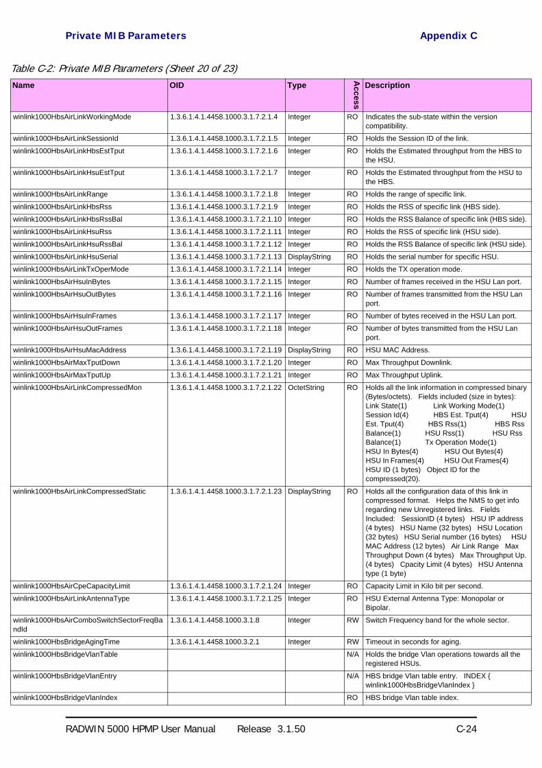
Private MIB Parameters Appendix C
RADWIN 5000 HPMP User Manual Release 3.1.50 C-24
winlink1000HbsAirLinkWorkingMode 1.3.6.1.4.1.4458.1000.3.1.7.2.1.4 Integer RO Indicates the sub-state within the version compatibility.
winlink1000HbsAirLinkSessionId 1.3.6.1.4.1.4458.1000.3.1.7.2.1.5 Integer RO Holds the Session ID of the link.
winlink1000HbsAirLinkHbsEstTput 1.3.6.1.4.1.4458.1000.3.1.7.2.1.6 Integer RO Holds the Estimated throughput from the HBS to the HSU.
winlink1000HbsAirLinkHsuEstTput 1.3.6.1.4.1.4458.1000.3.1.7.2.1.7 Integer RO Holds the Estimated throughput from the HSU to the HBS.
winlink1000HbsAirLinkRange 1.3.6.1.4.1.4458.1000.3.1.7.2.1.8 Integer RO Holds the range of specific link.
winlink1000HbsAirLinkHbsRss 1.3.6.1.4.1.4458.1000.3.1.7.2.1.9 Integer RO Holds the RSS of specific link (HBS side).
winlink1000HbsAirLinkHbsRssBal 1.3.6.1.4.1.4458.1000.3.1.7.2.1.10 Integer RO Holds the RSS Balance of specific link (HBS side).
winlink1000HbsAirLinkHsuRss 1.3.6.1.4.1.4458.1000.3.1.7.2.1.11 Integer RO Holds the RSS of specific link (HSU side).
winlink1000HbsAirLinkHsuRssBal 1.3.6.1.4.1.4458.1000.3.1.7.2.1.12 Integer RO Holds the RSS Balance of specific link (HSU side).
winlink1000HbsAirLinkHsuSerial 1.3.6.1.4.1.4458.1000.3.1.7.2.1.13 DisplayString RO Holds the serial number for specific HSU.
winlink1000HbsAirLinkTxOperMode 1.3.6.1.4.1.4458.1000.3.1.7.2.1.14 Integer RO Holds the TX operation mode.
winlink1000HbsAirHsuInBytes 1.3.6.1.4.1.4458.1000.3.1.7.2.1.15 Integer RO Number of frames received in the HSU Lan port.
winlink1000HbsAirHsuOutBytes 1.3.6.1.4.1.4458.1000.3.1.7.2.1.16 Integer RO Number of frames transmitted from the HSU Lan port.
winlink1000HbsAirHsuInFrames 1.3.6.1.4.1.4458.1000.3.1.7.2.1.17 Integer RO Number of bytes received in the HSU Lan port.
winlink1000HbsAirHsuOutFrames 1.3.6.1.4.1.4458.1000.3.1.7.2.1.18 Integer RO Number of bytes transmitted from the HSU Lan port.
winlink1000HbsAirHsuMacAddress 1.3.6.1.4.1.4458.1000.3.1.7.2.1.19 DisplayString RO HSU MAC Address.
winlink1000HbsAirMaxTputDown 1.3.6.1.4.1.4458.1000.3.1.7.2.1.20 Integer RO Max Throughput Downlink.
winlink1000HbsAirMaxTputUp 1.3.6.1.4.1.4458.1000.3.1.7.2.1.21 Integer RO Max Throughput Uplink.
winlink1000HbsAirLinkCompressedMon 1.3.6.1.4.1.4458.1000.3.1.7.2.1.22 OctetString RO Holds all the link information in compressed binary (Bytes/octets). Fields included (size in bytes): Link State(1) Link Working Mode(1) Session Id(4) HBS Est. Tput(4) HSU Est. Tput(4) HBS Rss(1) HBS Rss Balance(1) HSU Rss(1) HSU Rss Balance(1) Tx Operation Mode(1) HSU In Bytes(4) HSU Out Bytes(4) HSU In Frames(4) HSU Out Frames(4) HSU ID (1 bytes) Object ID for the compressed(20).
winlink1000HbsAirLinkCompressedStatic 1.3.6.1.4.1.4458.1000.3.1.7.2.1.23 DisplayString RO Holds all the configuration data of this link in compressed format. Helps the NMS to get info regarding new Unregistered links. Fields Included: SessionID (4 bytes) HSU IP address (4 bytes) HSU Name (32 bytes) HSU Location (32 bytes) HSU Serial number (16 bytes) HSU MAC Address (12 bytes) Air Link Range Max Throughput Down (4 bytes) Max Throughput Up. (4 bytes) Cpacity Limit (4 bytes) HSU Antenna type (1 byte)
winlink1000HbsAirCpeCapacityLimit 1.3.6.1.4.1.4458.1000.3.1.7.2.1.24 Integer RO Capacity Limit in Kilo bit per second.
winlink1000HbsAirLinkAntennaType 1.3.6.1.4.1.4458.1000.3.1.7.2.1.25 Integer RO HSU External Antenna Type: Monopolar or Bipolar.
winlink1000HbsAirComboSwitchSectorFreqBandId
1.3.6.1.4.1.4458.1000.3.1.8 Integer RW Switch Frequency band for the whole sector.
winlink1000HbsBridgeAgingTime 1.3.6.1.4.1.4458.1000.3.2.1 Integer RW Timeout in seconds for aging.
winlink1000HbsBridgeVlanTable N/A Holds the bridge Vlan operations towards all the registered HSUs.
winlink1000HbsBridgeVlanEntry N/A HBS bridge Vlan table entry. INDEX winlink1000HbsBridgeVlanIndex
winlink1000HbsBridgeVlanIndex RO HBS bridge Vlan table index.
Table C-2: Private MIB Parameters (Sheet 20 of 23)Name OID Type
Acc
ess
Description

Private MIB Parameters Appendix C
RADWIN 5000 HPMP User Manual Release 3.1.50 C-25
winlink1000HbsBridgeVlanIngress RW HBS bridge Vlan ingress.
winlink1000HbsBridgeVlanEgress RW HBS bridge Vlan egress.
winlink1000HbsBridgeVlanFilterIn RW HBS bridge Vlan filter in.
winlink1000HbsBridgeVlanFilterOut RW HBS bridge Vlan filter out.
winlink1000HbsBridgeVlanDoubleTag RW HBS bridge Vlan double tag.
winlink1000HbsBridgeVlanDefaultId RW HBS bridge Vlan default id.
winlink1000HbsBridgeMembershipTable N/A Holds the bridge membership relations for all the registered HSUs.
winlink1000HbsBridgeMembershipEntry N/A HBS bridge membership table entry. INDEX winlink1000HbsBridgeMembershipIndex
winlink1000HbsBridgeMembershipIndex 1.3.6.1.4.1.4458.1000.3.2.3.1.1 Integer RO HBS bridge membership table index.
winlink1000HbsBridgeMembershipState 1.3.6.1.4.1.4458.1000.3.2.3.1.2 Gauge RW HBS bridge membership state bitmap. Each bit represents Blocked/Opened relation (membership) between two HSUs. Blocked=0 (bit) Opened=1 (bit).
winlink1000HbsServiceCommandStr 1.3.6.1.4.1.4458.1000.3.3.1 DisplayString RW Ability to perform special command in the HBS. Format (string): Operation Index Session Param1 Param2 ....| ParamN The index and SessionID can be uniting to one parameter. On registered HSU it is HSU-ID and on Unregistered it is Session-ID.
winlink1000HbsServiceVlanTable N/A Holds the Vlan operations towards all the registered HSUs.
winlink1000HbsServiceVlanEntry N/A HBS service Vlan table entry. INDEX winlink1000HbsServiceVlanIndex
winlink1000HbsServiceVlanIndex 1.3.6.1.4.1.4458.1000.3.3.2.1.1.1 Integer RO HBS service Vlan table index.
winlink1000OduServiceVlanTblTag 1.3.6.1.4.1.4458.1000.3.3.2.1.1.2 Integer RW The VID to be used when adding TAG or adding Provider
winlink1000OduServiceVlanTblPri 1.3.6.1.4.1.4458.1000.3.3.2.1.1.3 Integer RW The Vlan priority 0-7 to be used when adding TAG or adding Provider
winlink1000OduServiceVlanTblMajorMode 1.3.6.1.4.1.4458.1000.3.3.2.1.1.4 Integer RW The Vlan major mode
winlink1000OduServiceVlanTblEgressMode 1.3.6.1.4.1.4458.1000.3.3.2.1.1.5 Integer RW The Vlan mode in the Egress direction
winlink1000OduServiceVlanTblIngressMode 1.3.6.1.4.1.4458.1000.3.3.2.1.1.6 Integer RW The Vlan mode in the Ingress direction
winlink1000OduServiceVlanTblEgressFilter1 1.3.6.1.4.1.4458.1000.3.3.2.1.1.7 Integer RW VLAN Filter1 VID
winlink1000OduServiceVlanTblEgressFilter2 1.3.6.1.4.1.4458.1000.3.3.2.1.1.8 Integer RW VLAN Filter2 VID
winlink1000OduServiceVlanTblEgressFilter3 1.3.6.1.4.1.4458.1000.3.3.2.1.1.9 Integer RW VLAN Filter3 VID
winlink1000OduServiceVlanTblEgressFilter4 1.3.6.1.4.1.4458.1000.3.3.2.1.1.10 Integer RW VLAN Filter4 VID
winlink1000HbsPerfMonThreshTable N/A Holds the performance monitor thresholds towards all the registered HSUs.
winlink1000HbsPerfMonThreshEntry N/A HBS performance monitor threshold table entry. INDEX winlink1000HbsPerfMonThreshIndex
winlink1000HbsPerfMonThreshIndex RO HBS performance monitor threshold table index.
winlink1000HbsPerfMonTxThresh1 1.3.6.1.4.1.4458.1000.3.4.1.1.2 Integer RW HBS performance monitor transmit power threshold.
winlink1000HbsPerfMonRxThresh1 1.3.6.1.4.1.4458.1000.3.4.1.1.3 Integer RW HBS performance monitor receive power threshold 1.
winlink1000HbsPerfMonRxThresh2 1.3.6.1.4.1.4458.1000.3.4.1.1.4 Integer RW HBS performance monitor receive power threshold 2.
winlink1000HbsPerfMonBBERThresh1 1.3.6.1.4.1.4458.1000.3.4.1.1.5 Integer RW HBS performance monitor BBER threshold.
winlink1000HbsPerfMonEstThroughputThreshKbps
1.3.6.1.4.1.4458.1000.3.4.1.1.6 Integer RW HBS performance monitor estimated throughput Threshold.
winlink1000HbsPerfMonHighTrafficThreshKbps
1.3.6.1.4.1.4458.1000.3.4.1.1.7 Integer RW HBS performance monitor high traffic threshold.
Table C-2: Private MIB Parameters (Sheet 21 of 23)Name OID Type
Acc
ess
Description

Private MIB Parameters Appendix C
RADWIN 5000 HPMP User Manual Release 3.1.50 C-26
winlink1000HbsPerfMonAirGenCurrTable N/A This table defines/keeps the ethernet counters of the current 15 min interval.
winlink1000HbsPerfMonAirGenCurrEntry N/A This is an entry in the Current Interval Table. INDEX ifIndex
winlink1000HbsPerfMonAirGenCurrRxMBytes 1.3.6.1.4.1.4458.1000.3.4.2.1.1 Gauge RO Current RX Mega Bytes starting from the present 15 minutes period.
winlink1000HbsPerfMonAirGenCurrTxMBytes 1.3.6.1.4.1.4458.1000.3.4.2.1.2 Gauge RO Current Transmit Mega Bytes starting from the present 15 minutes period.
winlink1000HbsPerfMonAirGenCurrEthCapacityThreshUnder
1.3.6.1.4.1.4458.1000.3.4.2.1.3 Gauge RO The number of times throughput was below threshold in the present 15 minutes period. Relevant for point to point systems.
winlink1000HbsPerfMonAirGenCurrHighTrafficThreshExceed
1.3.6.1.4.1.4458.1000.3.4.2.1.4 Gauge RO The number of times actual traffic was above threshold in the present 15 minutes period.
winlink1000HbsPerfMonAirGenCurrActiveSeconds
1.3.6.1.4.1.4458.1000.3.4.2.1.5 Gauge RO The number of seconds in which RPL Ethernet swervice was not blocked in the present 15 minutes period.
winlink1000HbsPerfMonAirGenIntervalTable N/A This table defines/keeps the ethernet counters of the last day (in resolution of 15 min intervals).
winlink1000HbsPerfMonAirGenIntervalEntry N/A This is an entry in the Interval Table. INDEX ifIndex winlink1000HbsPerfMonAirGenIntervalIdx
winlink1000HbsPerfMonAirGenIntervalIdx RO This table is indexed per interval number. Each interval is of 15 minutes and the oldest is 96.
winlink1000HbsPerfMonAirGenIntervalRxMBytes
RO Current RX Mega Bytes per interval.
winlink1000HbsPerfMonAirGenIntervalTxMBytes
RO Current Transmit Mega Bytes per interval.
winlink1000HbsPerfMonAirGenIntervalEthCapacityThreshUnder
RO The number of times throughput was below threshold in the each interval. Relevant for point to point systems.
winlink1000HbsPerfMonAirGenIntervalHighTrafficThreshExceed
RO The number of times actual traffic was above threshold in the each interval.
winlink1000HbsPerfMonAirGenIntervalActiveSeconds
RO The number of seconds in which RPL Ethernet service was not blocked in the each interval.
winlink1000HbsPerfMonAirGenDayTable N/A This table defines/keeps the ethernet counters of the last month (in resolution of days).
winlink1000HbsPerfMonAirGenDayEntry N/A This is an entry in the Days Table. INDEX ifIndex winlink1000HbsPerfMonAirGenDayIdx
winlink1000HbsPerfMonAirGenDayIdx RO This table is indexed per Day number. Each interval is of 15 minutes and the oldest is 96.
winlink1000HbsPerfMonAirGenDayRxMBytes RO Current RX Mega Bytes per day.
winlink1000HbsPerfMonAirGenDayTxMBytes RO Current Transmit Mega Bytes per day.
winlink1000HbsPerfMonAirGenDayEthCapacityThreshUnder
RO The number of times throughput was below threshold each day. Relevant for point to point systems.
winlink1000HbsPerfMonAirGenDayHighTrafficThreshExceed
RO The number of times actual traffic was above threshold each day.
winlink1000HbsPerfMonAirGenDayActiveSeconds
RO The number of seconds in which RPL Ethernet service was not blocked each day.
winlink1000HsuAirState RO Holds the state of the HSU.
winlink1000HsuAirLinkState RO Holds the state of the HSU link.
winlink1000HsuAirHsuId RO Holds the HSU ID as sent by the HBS.
winlink1000HsuAirLocalDeregister RW Performs Local HSU Deregistration when - only when the link is off.
Table C-2: Private MIB Parameters (Sheet 22 of 23)Name OID Type
Acc
ess
Description

MIB Traps Appendix C
RADWIN 5000 HPMP User Manual Release 3.1.50 C-27
MIB Traps
General
Each ODU can be configured with up to 10 different trap destinations. When the link is oper-ational, each ODU sends traps originating from both Site A and Site B.
The source IP address of the trap is the sending ODU. The trap originator can be identified by the trap Community string or by the trap description text.
Each trap contains a trap description and additional relevant information such as alarm sever-ity, interface index, time stamp and additional parameters.
winlink1000HsuAirRemoteCompressedMon RO Holds all the configuration data of The HBS in compressed format. Fields Included: Rss (1 byte) Rss Balance (1 byte) Est. Tput (4 bytes) In Bytes of the whole sector (4 bytes) Out Bytes of the whole sector (4 bytes) In Frames of the whole sector (4 bytes) Out Frames of the whole sector (4 bytes) Max Throughput DownLink (4 bytes) Max Throughput UpLink (4 bytes)
winlink1000HsuAirRemoteCompressedStatic RO Holds all the configuration data of the HBS in a compressed format. Helps the NMS to get info regarding new Unregistered links. Fields Included: Location (32 bytes) IP address (8 bytes in hexa) Subnet mask (8 bytes in hexa) HBS Antenna type (1 byte)
winlink1000GeneralTrapDescription 1.3.6.1.4.1.4458.1000.100.1 DisplayString RO Trap's Description. Used for Trap parameters.
winlink1000GeneralTrapSeverity 1.3.6.1.4.1.4458.1000.100.2 Integer RO Trap's Severity. Used for Trap parameters.
winlink1000GeneralCookie 1.3.6.1.4.1.4458.1000.100.3 DisplayString RW Reserved for the Manager application provided with the product used for saving user preferences affecting ODU operation.
winlink1000GeneralEcChangesCounter 1.3.6.1.4.1.4458.1000.100.4 Integer RO This counter is initialized to 0 after a device reset and is incremented upon each element constant write operation via SNMP or Telnet.
winlink1000GeneralTelnetSupport 1.3.6.1.4.1.4458.1000.100.5 Integer RW Enable/Disable Telnet protocol.
winlink1000GeneralWISupport RW Enable/Disable Web Interface protocol. Mandatory Disabled - No option to enable the feature. Mandatory Enabled - No option to disable the feature.
Table C-2: Private MIB Parameters (Sheet 23 of 23)Name OID Type
Acc
ess
Description

Trap Parameters Appendix C
RADWIN 5000 HPMP User Manual Release 3.1.50 C-28
Trap ParametersTable C-3: MIB Traps (Sheet 1 of 5)Name ID Severity Description
trunkStateChanged 1 normal Indicates a change in the state of one of the TDM trunks. Raised by both sides of the link. Contains 3 parameters: 1 - Description: TDM Interface %n - %x 2 - %n: Is the trunk number 3 - %x: Is the alarm type and can be one of the following: Normal AIS LOS Loopback
linkUp 2 normal Indicates that the radio link is up. Contains a single parameter which is its description: 1 - Description: Radio Link - Sync on channel %n GHz. %n Is the channel frequency in GHz.
linkDown 3 critical Indicates that the radio link is down. Contains a single parameter which is its description: 1 - Description: Radio Link - Out of Sync. The reason is: %s. %s Is the reason.
detectIDU 4 normal Indicates that the IDU was detected. Raised by both sides of the link. Contains a single parameter which is its description: 1 - Description: IDU of Type %s was Detected. %s Is the type of the IDU.
disconnectIDU 5 major Indicates that the IDU was disconnected. Raised by both sides of the link. Contains a single parameter which is its description: 1 - Description: IDU Disconnected.
mismatchIDU 6 major Indicates a mismatch between the IDUs. Raised by the master only. Contains a single parameter which is its description: 1 - Description: IDUs Mismatch: One Side is %s and the Other is %s. %s Is the type of the IDU.
openedServices 7 normal Indicates that services were opened. Raised by the master only. Contains 3 parameters: 1 - Description: %n2 out of %n1 Requested TDM Trunks have been Opened 2 - %n1: Is the requested number of TDM truncks 3 - %n2: Is the actual number of TDM trunks that were opened
closedServices 8 normal Indicates that services were closed. Raised by the master only. Contains a single parameter which is its description: 1 - Description: TDM Service has been closed. The reason is: %s. %s Is the reason.
incompatibleODUs 9 critical Indicates that the ODUs are incompatible. Contains a single parameter which is its description: 1 - Description: Incompatible ODUs.
incompatibleIDUs 10 major Indicates that the IDUs are incompatible. Contains a single parameter which is its description: 1 - Description: Incompatible IDUs.
incompatibleOduIdu 11 major Indicates that the ODU and IDU are incompatible. Contains a single parameter which is its description: 1 - Description: The IDU could not be loaded. The reason is: %s. %s Is the incompatibility type.
probingChannel 12 normal Indicates that the ODU is monitoring radar activity. Contains a single parameter which is its description: 1 - Description: Monitoring for radar activity on channel %n GHz. %n is the channel frequency in GHz.
radarDetected 13 normal Indicates that radar activity was detected. Contains a single parameter which is its description: 1 - Description: Radar activity was detected in %s on channel %n GHz. %s Is the site name. %n Is the channel frequency in GHz.
transmittingOnChannel 14 normal Indicates that the ODU is transmitting on channel. Contains a single parameter which is its description: 1 - Description: Transmitting on channel %n GHz. %n Is the channel frequency in GHz.
scanningChannels 15 normal Indicates that the ODU is scanning channels. Contains a single parameter which is its description: 1 - Description: Channel scanning in progress.
incompatiblePartner 16 critical Indicates that configuration problem was detected and that link installation is required in order to fix it. Contains a single parameter which is its description: 1 - Description: Configuration problem detected. Link installation required.
timeClockSet 17 normal Indicates that the ODU time clock was set. Contains a single parameter which is its description: 1 - Description: The time was set to: %p. %p Is the date and time.
configurationChanged 18 normal Indicates that the ODU recovered from an error but there are configuration changes. Contains two parameters: 1 - Description: Configuration changed. Error code is: %n. 2 - %n number.

Trap Parameters Appendix C
RADWIN 5000 HPMP User Manual Release 3.1.50 C-29
hssOpStateChangedToINU 19 normal Indicates that the HSS operating state was changed to INU type. Contains a single parameter which is its description: 1 - Description: HSS operating state was changed to: INU.
hssOpStateChangedToHSM 20 normal Indicates that the HSS operating state was changed to HSM type. Contains a single parameter which is its description: 1 - Description: HSS operating state was changed to: HSM.
hssOpStateChangedToHSC 21 normal Indicates that the HSS operating state was changed to HSC type. Contains a single parameter which is its description: 1 - Description: HSS operating state was changed to: HSC_DT/HSC_CT.
vlanModeActive 22 normal Indicates to non-VLAN PC that after 2 minutes the system will support only VLAN tag on management interface. Contains a single parameter which is its description: 1 - Description: VLAN Mode is active. Non-VLAN traffic will be blocked in 2 minutes.
spectrumAnalysis 23 normal Indicates that the ODU is in Spectrum Analysis mode. Contains a single parameter which is its description: 1 - Description: Spectrum analysis in progress.
hbsHsuDeregisteredOffline 24 normal Indicates that a HSU was deregistered offline (out of link)
hbsHsuDeregisteredSuccessfully 25 normal Indicates that a HSU was deregistered successfully
hbsHsuRegisteredSuccessfully 26 normal Indicates that a HSU was registered successfully
hbsHsuRegistrationFailed 27 normal Indicates that registration has failed
hbsHsuViolatedState 28 normal Indicates (on the HBS side) that a HSU is is violated state
hsuViolatedState 29 normal Indicates (on the HSU side) that the HSU is is violated state
hbsUnregisteredSynchronizedHsu 30 normal Indicates an unregistered HSU has been synchronized.
hbsUnregisteredUnsynchronizedHsu 31 normal Indicates an unregistered HSU lost synchronization.
cableQuality 32 normal 1Gbps rate is not supported due to bad line quality.
httpAuthentication 33 normal HTTP Authentication Failure.
telnetAuthentication 34 normal Telnet Authentication Failure.
tdmServiceAlarm 100 major Indicates that TDM Service is in alarm state. Contains a single parameter which is its description: 1 - Description: TDM Service - Alarm.
ethServiceClosed 101 major Indicates that Ethernet Service is closed. Contains a single parameter which is its description: 1 - Description: Ethernet Service is closed.
ethServiceNotPermitted 102 major Indicates that Ethernet Service is not permitted. Contains a single parameter which is its description: 1 - Description: A valid IDU could not be detected at %s. Please check your configuration. %s - Is the Local Site name or Remote Site name or both sides of the Link.
encryptionAlarm 103 major Indicates an encryption key mismatch. Contains a single parameter which is its description: 1 - Description: Encryption Status - Failed. No Services are available.
changeLinkPasswordAlarm 104 major Indicates that a failure has occurred while attempting to change the Link Password. Contains a single parameter which is its description: 1 - Description: Failed to change the Link Password at/on: %s. %s - Is the Local Site name or Remote Site name or both sides of the Link.
externalAlarmInPort1Alarm 105 major The trap is sent every time an alarm occurs in the External Alarm Input of port #1. Contains a single parameter which is its description: 1 - Description: External Alarm 1 - <User Text> - Alarm.
externalAlarmInPort2Alarm 106 major The trap is sent every time an alarm occurs in the External Alarm Input of port #2. Contains a single parameter which is its description: 1 - Description: External Alarm 2 - <User Text> - Alarm.
bitFailedAlarm 107 major The trap is sent if there is no way to recover from the situation.Contains two parameters: 1 - Description: ODU power up built in test failed. Error code is: %n 2 - %n number
wrongConfigurationLoadedAlarm 108 major The trap is sent if there is a way to recover from the situation.Contains two parameters: 1 - Description: Wrong configuration loaded. Error code is: %n 2 - %n number
lanPort1DisconnectedAlarm 109 major Indicates the LAN port 1 status changed to disconnected.Contains a single parameter which is its description: 1 - Description: LAN port 1 status changed to disconnected.
Table C-3: MIB Traps (Sheet 2 of 5)Name ID Severity Description

Trap Parameters Appendix C
RADWIN 5000 HPMP User Manual Release 3.1.50 C-30
lanPort2DisconnectedAlarm 110 major Indicates the LAN port 2 status changed to disconnected.Contains a single parameter which is its description: 1 - Description: LAN port 2 status changed to disconnected.
mngPortDisconnectedAlarm 111 major Indicates the management port status changed to disconnected.Contains a single parameter which is its description: 1 - Description: Management port status changed to disconnected.
externalAlarmInPort3Alarm 112 major The trap is sent every time an alarm occurs in the External Alarm Input of port #3. Contains a single parameter which is its description: 1 - Description: External Alarm 3 - <User Text> - Alarm.
externalAlarmInPort4Alarm 113 major The trap is sent every time an alarm occurs in the External Alarm Input of port #4. Contains a single parameter which is its description: 1 - Description: External Alarm 4 - <User Text> - Alarm.
swVersionsMismatchFullCompatibilityAlarm 114 warning The trap is sent if SW versions mismatch with full link functionality. Contains a single parameter which is its description: 1 - Description: Software versions mismatch - full link functionality
swVersionsMismatchRestrictedCompatibilityAlarm 115 minor The trap is sent if SW versions mismatch with restricted link functionality. Contains a single parameter which is its description: 1 - Description: Software versions mismatch - restricted link functionality
swVersionsMismatchSoftwareUpgradeRequired 116 major The trap is sent if SW versions mismatch and SW upgrade is required. Contains a single parameter which is its description: 1 - Description: Software versions mismatch - Software upgrade required
swVersionsIncompatible 117 critical The trap is sent if SW versions are incompatible. Contains a single parameter which is its description: 1 - Description: SW Versions incompatible
hssMultipleSourcesDetectedAlarm 118 major Indicates that multiple sync pulse sources were detected. Contains a single parameter which is its description: 1 - Description: HSS multiple sync sources were detected.
hssSyncToProperSourceStoppedAlarm 119 major Indicates that synchronization to a proper sync pulse source was stopped. Contains a single parameter which is its description: 1 - Description: HSS sync pulse - Down. The reason is: %s. %s - Is the reason for the sync down.
hssSyncPulseDetectedAlarm 120 major Indicates that HSS additional sync pulse was detected. Contains a single parameter which is its description: 1 - Description: HSS additional sync pulse was detected.
tdmBackupAlarm 121 major Indicates that the TDM backup link was activated. Contains a single parameter which is its description: 1 - Description: TDM backup alarm - backup link was activated.
linkLockUnauthorizedRemoteODU 122 major Indicates that the remote ODU is unauthorized. Contains a single parameter which is its description: 1 - Description: Unauthorized remote ODU connection rejected.
linkLockUnauthorizedODU 123 major Indicates that the ODU is unauthorized. Contains a single parameter which is its description: 1 - Description: Unauthorized ODU connection rejected.
hotStandbyAlarm 124 major Indicates that the hot standby secondary link was activated. Contains a single parameter which is its description: 1 - Description: Secondary Link Is Active.
sfpInsertion 126 normal Indicates that a device was inserted to SFP Port
sfpPort1DisconnectedAlarm 127 major Indicates the SFP port 1 status changed to disconnected.Contains a single parameter which is its description: 1 - Description: SFP port 1 status changed to disconnected.
ringRplStateActiveAlarm 128 major RPL state changed to Active.
desiredRatioCanNotBeAppliedAlarm 129 normal Indicates Desired UL/DL RAtio Can Not Be Applied.
cbwMismatch 130 major Indicates that a Channel Bandwidth mismatch was detected.Contains two parameters: 1 - Description: Channel Bandwidth Mismatch: one side is %n0 MHz and the other is %n1 MHz. %n0 is the local Channel Bandwidth value in MHz. %n1 is the remoet Channel Bandwidth value in MHz.
gpsNotSynchronized 131 major Indicates that the GPS is not synchronized with satellites. Pulses are self generated.
Table C-3: MIB Traps (Sheet 3 of 5)Name ID Severity Description

Trap Parameters Appendix C
RADWIN 5000 HPMP User Manual Release 3.1.50 C-31
pdTooHighDueCbwLimitations 132 major Indicates that link cannot be established because link range is too large for channel bandwidth.
hbsEncryptionAlarm 133 major Indicates an encryption key mismatch. Contains a single parameter which is its description including the HSU's name
hbsEhServiceClosedToHsu 134 major Indicates an encryption key mismatch. Contains a single parameter which is its description including the HSU's name
hbsUnsynchronizedHsuAlarm 135 warning Indicates a registered HSU lost synchronization.
hbsInactiveHbsAlarm 136 major Indicates HBS is InActive.
incompatibleHsu 137 critical Indicates that the HSU is not compatible to HBS. Contains a single parameter which is its description: 1 - Description: Incompatible ODUs.
hsuUnsupportedBeacon 138 warning Indicates an unsupported beacon has arrived at HSU
tdmServiceClear 200 major Indicates that TDM Service fault is cleared. Contains a single parameter which is its description: 1 - Description: TDM Service - Normal.
ethServiceOpened 201 normal Indicates that Ethernet Service has been opened. Contains a single parameter which is its description: 1 - Description: Ethernet Service has been opened.
encryptionClear 203 normal Indicates that encryption is OK. Contains a single parameter which is its description: 1 - Description: Encryption Status - Normal.
changeLinkPasswordClear 204 normal Indicates that the Link Password was changed successfully. Contains a single parameter which is its description: 1 - Description: Link Password has been changed at/on: %s. %s - Is the Local Site name or Remote Site name or both sides of the Link.
externalAlarmInPort1Clear 205 normal This Trap is sent every time an External Alarm Input fault of port # 1 is cleared. Contains a single parameter which is its description: 1 - Description: External Alarm 1 - <User Text> - Alarm Cleared.
externalAlarmInPort2Clear 206 normal This Trap is sent every time an External Alarm Input fault of port # 2 is cleared. Contains a single parameter which is its description: 1 - Description: External Alarm 2 - <User Text> - Alarm Cleared.
lanPort1Clear 209 normal Indicates the LAN port 1 status changed to connected. Contains two parameters: 1 - Description: LAN port 1 status changed to connected - %s 2 - %s Is the Eth. mode (speed & duplex)
lanPort2Clear 210 normal Indicates the LAN port 2 status changed to connected. Contains two parameters: 1 - Description: LAN port 2 status changed to connected - %s. 2 - %s Is the Eth. mode (speed & duplex).
mngPortClear 211 normal Indicates the management port status changed to connected. Contains two parameters: 1 - Description: Management port status changed to connected - %s 2 - %s Is the Eth. mode (speed & duplex)
externalAlarmInPort3Clear 212 normal This Trap is sent every time an External Alarm Input fault of port # 3 is cleared. Contains a single parameter which is its description: 1 - Description: External Alarm 3 - <User Text> - Alarm Cleared.
externalAlarmInPort4Clear 213 normal This Trap is sent every time an External Alarm Input fault of port # 4 is cleared. Contains a single parameter which is its description: 1 - Description: External Alarm 4 - <User Text> - Alarm Cleared.
swVersionsMatchFullCompatibilityClear 214 normal The trap is sent if SW versions match. Contains a single parameter which is its description: 1 - Description: Software Versions compatible
swVersionsMatchRestrictedCompatibilityClear 215 normal The trap is sent if SW versions match and link functionality is not restricted. Contains a single parameter which is its description: 1 - Description: Software Versions compatible
swVersionsMatchSoftwareUpgradeRequiredClear 216 normal The trap is sent if SW versions match and SW upgrade is successful. Contains a single parameter which is its description: 1 - Description: Software Versions compatible
swVersionsCompatibleClear 217 normal The trap is sent if SW versions compatible Contains a single parameter which is its description: 1 - Description: Software Versions compatible
hssMultipleSourcesDisappearedClear 218 normal Indicates that multiple sync pulse sources disappeared. Contains a single parameter which is its description: 1 - Description: HSS multiple sync pulse sources disappeared.
Table C-3: MIB Traps (Sheet 4 of 5)Name ID Severity Description

RADWIN Manager Traps Appendix C
RADWIN 5000 HPMP User Manual Release 3.1.50 C-32
RADWIN Manager Traps
The RADWIN Manager application issues traps to indicate various events. These traps are shown in the RADWIN Managerr Events Log.
A list of Trap Messages as displayed by the RADWIN Manager is shown in Table 8-4.
hssSyncToProperSourceAchievedClear 219 normal Indicates that synchronization to a proper Sync source was achieved. Contains a single parameter which is its description: 1 - Description: HSS sync pulse - Up.
hssSyncPulseDisappearedClear 220 normal Indicates that HSS additional sync pulse disappeared. Contains a single parameter which is its description: 1 - Description: HSS additional sync pulse was disappeared.
tdmBackupClear 221 normal Indicates that the TDM main link was activated. Contains a single parameter which is its description: 1 - Description: TDM main link was activated.
linkLockAuthorizedRemoteODU 222 normal Indicates that the remote ODU is authorized. Contains a single parameter which is its description: 1 - Description: Authorized remote ODU connection accepted.
linkLockAuthorizedODU 223 normal Indicates that the ODU is authorized. Contains a single parameter which is its description: 1 - Description: Authorized ODU connection permitted.
linkAuthenticationDisabled 224 normal Indicates that the Link Lock is disabled. Contains a single parameter which is its description: 1 - Description: Link Authentication has been disabled.
hotStandbyClear 225 normal Indicates that the Primary Link Was Activated. Contains a single parameter which is its description: 1 - Description: Primary Link Is Active.
sfpExtraction 226 normal Indicates that a device was extracted from SFP Port
sfpPort1Clear 227 normal Indicates the SFP port 1 status changed to connected. Contains two parameters: 1 - Description: SFP port 1 status changed to connected - %s 2 - %s Is the Eth. mode (speed & duplex)
compatibleIdus 228 normal Indicates that the ODU has identified compatible Idus on both sides of the link.
desiredRatioCanNotBeAppliedClear 229 normal Indicates Current UL/DL Ratio Is Equal To Desired Ratio.
cbwMatch 230 normal Indicates that a Channel Bandwidth match was detected. Contains a single parameter which is its description: 1 - Channel Bandwidth value in MHz.
switchCbwAndChannel 231 normal Indicates that the system is switching Channel Bandwidth and channel frequency. Contains two parameters: 1 - Switching to Channel Bandwith %n0 MHz and to channel %n1 GHz.
ringRplStateIdle 232 normal RPL state changed to Idle.
ringEthServiceStatus 233 normal Indicates Ethernet service's state - blocked \ unblocked. Contains a single parameter: 1 - Description: Ethernet's state (blocked \ unblocked)
ringFirstRpmReceived 234 normal Ring application: in non-RPL link indicates first from a specific RPL was received. Contains a single parameter: 1 - Description: RPM's VLAN ID
ringEthernetSrviceUnblockedTO 235 normal Ring application: in non-RPL link Ethernet service is unblocked due to RPM timeout.
gpsSynchronized 236 normal Indicates that the GPS is synchronized with satellites.
hbsEncryptionClear 237 normal Indicates that encryption is OK. Contains a single parameter which is its description including the HSU's name
hbsEhServiceOpenedToHsu 238 normal Indicates that encryption is OK. Contains a single parameter which is its description including the HSU's name
hbsSynchronizedHsuAlarm 239 normal Indicates a registered HSU is synchronized.
hbsActiveHbs 240 normal Indicates when HBS has been activated.
switchCBW 241 normal Switching Channel Bandwidth.
Table C-3: MIB Traps (Sheet 5 of 5)Name ID Severity Description
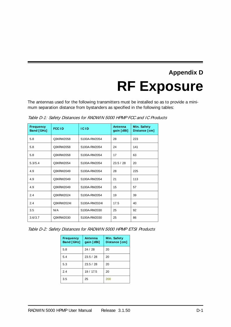
RADWIN 5000 HPMP User Manual Release 3.1.50 D-1
Appendix D
RF ExposureThe antennas used for the following transmitters must be installed so as to provide a mini-mum separation distance from bystanders as specified in the following tables:
Table D-1: Safety Distances for RADWIN 5000 HPMP FCC and IC Products
Frequency Band [GHz] FCC ID IC ID Antenna
gain [dBi]Min. Safety Distance [cm]
5.8 Q3KRW2058 5100A-RW2054 28 223
5.8 Q3KRW2058 5100A-RW2054 24 141
5.8 Q3KRW2058 5100A-RW2054 17 63
5.3/5.4 Q3KRW2054 5100A-RW2054 23.5 / 28 20
4.9 Q3KRW2049 5100A-RW2054 28 225
4.9 Q3KRW2049 5100A-RW2054 21 113
4.9 Q3KRW2049 5100A-RW2054 15 57
2.4 Q3KRW2024 5100A-RW2054 19 39
2.4 Q3KRW2024I 5100A-RW2024I 17.5 40
3.5 N/A 5100A-RW2030 25 92
3.6/3.7 Q3KRW2030 5100A-RW2030 25 86
Table D-2: Safety Distances for RADWIN 5000 HPMP ETSI Products
Frequency Band [GHz]
Antenna gain [dBi]
Min. Safety Distance [cm]
5.8 24 / 28 20
5.4 23.5 / 28 20
5.3 23.5 / 28 20
2.4 19 / 17.5 20
3.5 25 200

RADWIN 5000 HPMP User Manual Release 3.1.50 E-1
Appendix E
Setting AntennaParameters
Antenna Issues
The choice of Tx Power, antenna gain and cable loss (between the radio and the antenna) determines the EIRP and is affected by such considerations as radio limitations and regulatory restrictions.
Before proceeding to antenna installation details, the following background information should be considered:
About Single and Dual Antennas
Each RADWIN 5000 HPMP ODU is made of two radio transceivers (radios). The radios make use of algorithms that utilize both MIMO and Diversity resulting in enhanced capacity, range and link availability. The number of antennas (i.e. radios) used is determined by user configu-ration and by automatic system decisions, explained below.
Dual Antennas at the HBS and a HSU
When using dual antennas at both sites (single bipolar antenna or two mo-unipolar antennas) you can choose between MIMO Mode and Diversity Mode.
MIMO Mode
With MIMO the system doubles the link capacity. At the same time, it keeps the same rate and modulation per radio as was used with single antenna, thus increasing capacity, range and availability.
For example with a dual antenna RADWIN 5000 HPMP can transmit at modulation of 64QAM and FEC of 5/6 and get an air rate of 130 Mbps, compared to 65 Mbps with single antenna.
To work in this mode, each antenna port must be connected to an antenna, the RSS level in both receivers should be balanced and a minimal separation between the antennas must be maintained. (For example, by using dual polarization antennas a cross polarization separation is attained).

Single Antennas at Both Sites Appendix E
RADWIN 5000 HPMP User Manual Release 3.1.50 E-2
Upon selecting Antenna Type as Dual, RADWIN 5000 HPMP automatically selects MIMO mode and doubles the air rates.
RADWIN Manager indicates a case of unbalanced RSS between the two antennas in the HBS panels.
Diversity Mode
Diversity Mode uses two antennas to improve the quality and reliability of the link. Often, there is not a clear line-of-sight (LOS) between transmitter and receiver. Instead the signal is reflected along multiple paths before if-ally being received.
Each such “bounce” can introduce phase shifts, time delays, attenuations, and even distor-tions that can destructively interfere with one another at the aperture of the receiving antenna. Antenna diversity is especially effective at mitigating these multi-path situations.
This is because multiple antennas afford a receiver several recordings of the same signal. Each antenna will be exposed to a different interference envy-remnant. Thus, if one antenna is undergoing a deep fade, it is likely that another has a sufficient signal. Collectively such a system can provide a robust link.
Antenna diversity requires antenna separation which is possible by using a dual-polarization antenna or by two spatially separated antennas.
Use Diversity instead of MIMO in the following situations:
• When the system cannot operate in MIMO Mode• When one of the receivers has high interference compared to the second receiver (i.e.
the system is “unbalanced”)• When you achieve higher capacity in Diversity Mode than in MIMO Mode• When high robustness is of importance and the capacity of Diversity Mode is sufficient
(up to 25 Mbps full duplex)
Single Antennas at Both Sites
By selecting a single antenna at the HBS and HSU, the ODUs operate with a single radio that is connected to the ANT 1 connector. The second radio is automatically shut down.
Single at One Site, Dual Antennas at the Other
In this mode one of the sites uses the ODU with a single antenna while the other site uses the ODU with a dual antenna.
The advantages in this mode in comparison to using a single antenna in both sites are dou-bled total Tx Power and additional polarization and/or space diversity (depending on the polarization of installed antennas).
The air rates used in this mode are same as when using single antennas in both sites.
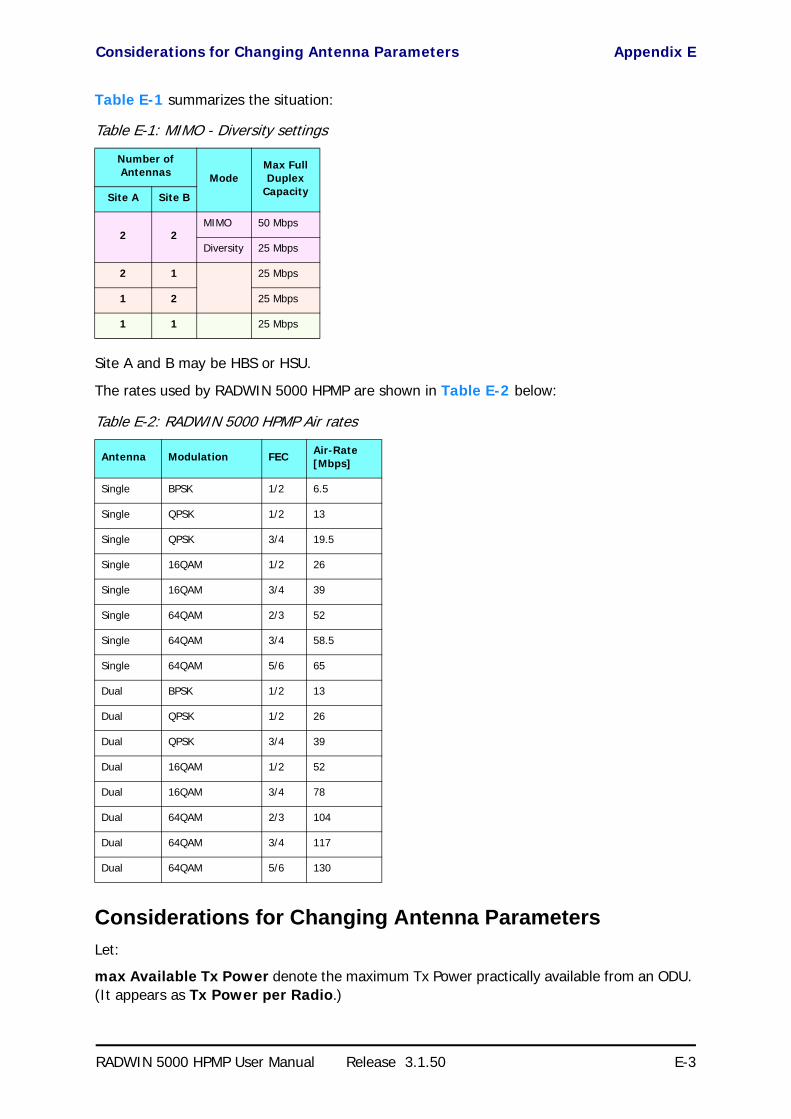
Considerations for Changing Antenna Parameters Appendix E
RADWIN 5000 HPMP User Manual Release 3.1.50 E-3
Table E-1 summarizes the situation:
Site A and B may be HBS or HSU.
The rates used by RADWIN 5000 HPMP are shown in Table E-2 below:
Considerations for Changing Antenna Parameters
Let:
max Available Tx Power denote the maximum Tx Power practically available from an ODU. (It appears as Tx Power per Radio.)
Table E-1: MIMO - Diversity settings
Number of Antennas Mode
Max Full Duplex
CapacitySite A Site B
2 2MIMO 50 Mbps
Diversity 25 Mbps
2 1 25 Mbps
1 2 25 Mbps
1 1 25 Mbps
Table E-2: RADWIN 5000 HPMP Air rates
Antenna Modulation FEC Air-Rate [Mbps]
Single BPSK 1/2 6.5
Single QPSK 1/2 13
Single QPSK 3/4 19.5
Single 16QAM 1/2 26
Single 16QAM 3/4 39
Single 64QAM 2/3 52
Single 64QAM 3/4 58.5
Single 64QAM 5/6 65
Dual BPSK 1/2 13
Dual QPSK 1/2 26
Dual QPSK 3/4 39
Dual 16QAM 1/2 52
Dual 16QAM 3/4 78
Dual 64QAM 2/3 104
Dual 64QAM 3/4 117
Dual 64QAM 5/6 130

Considerations for Changing Antenna Parameters Appendix E
RADWIN 5000 HPMP User Manual Release 3.1.50 E-4
maxRegEIRP denote the maximum EIRP available by regulation. It will be determined by three factors:
• per band/regulation
• per channel bandwidth• antenna gain
maxRegTxPower denote the maximum regulatory Tx Power for the equipment, also having regard the above three points.
Then, the following relationship must be satisfied: ... (*)
The Tx Power (per radio) indicates the power of each radio inside the ODU and is used for Link Budget Calculations. The Tx Power (System) shows the total transmission power of the ODU and is used to calculate the EIRP according to regulations.
The inequality (*) above is always satisfied by the system in accordance with the relevant regulation.
The precise relationship between the items in inequality (*) is as follows:
• Required Tx Power (per radio) will be adjusted down to the lesser of the value entered and maxAvailableTxPower
• Tx Power (system) is maxAvailableTxPower + 3 (for 2 radios)
• Max EIRP is maxRegEIRP.• EIRP is maxAvailableTx Power + Antenna Gain - Cable Loss
Notes
• To see the relationship between Tx Power (radio) and Tx Power (system), note that so that if you
double the power in milliWatts (for two radios) then dBm will increase by .
• The Max EIRP level will be automatically set according to the selected band and regulation.
• The EIRP level is the sum of the System Tx Power and the Antenna Gain minus the Cable Loss.
• The Max EIRP level will be automatically set according to the selected band and regulation.
• The EIRP level is the sum of the System Tx Power and the Antenna Gain minus the Cable Loss.
maxAvailableTxPower min maxRegEIRPAntennaGain CableLoss maxRegTxPower+–
()
dBm 10 milliWatt10log=
10 2 310log

RADWIN 5000 HPMP User Manual Release 3.1.50 F-1
Appendix F
Regional Notice: FrenchCanadian
Procédures de sécurité
Généralités
Avant de manipuler du matériel connecté à des lignes électriques ou de télécommunications, il est conseillé de se défaire de bijoux ou de tout autre objet métallique qui pourrait entrer en contact avec les éléments sous tension.
Mise à la terre
Tous les produits RADWIN doivent être mis à la terre pendant l'usage courant. La mise à la terre est assurée en reliant la fiche d'alimentation à une prise de courant avec une protection de terre. En outre:
• La cosse de masse sur l'IDU-C doit être constamment connectée à la protection de terre, par un câble de diamètre de 18 AWG ou plus. Le matériel monté sur rack doit être installé seulement sur des racks ou armoires reliés à la terre
• Une ODU doit mise à la terre par un câble de diamètre de 12 AWG ou plus• Il ne doit pas y avoir de fusibles ou d'interrupteurs sur la connection à la terre
De plus:
• Il faut toujours connecter la terre en premier et la déconnecter en dernier• Il ne faut jamais connecter les câbles de télécommunication à du matériel non à la
terre• Il faut s'assurer que tous les autres câbles sont déconnectés avant de déconnecter la
terre
Protection contre la foudre
L'utilisation de dispositifs de protection contre la foudre dépend des exigences réglementaires et de l'utilisateur final. Toutes les unités extérieures RADWIN sont conçues avec des circuits de limitation de surtension afin de minimiser les risques de dommages dus à la foudre. RAD-

Précautions de sécurité pendant le montage de ODU Appendix F
RADWIN 5000 HPMP User Manual Release 3.1.50 F-2
WIN conseille l'utilisation d'un dispositif de parafoudre supplémentaire afin de protéger le matériel de coups de foudre proches.
Matériel supplémentaire requis
L'équipement requis pour l'installation du matériel est le suivant:
• Pince à sertir RJ-45 (si un câble pré-assemblé ODU/IDU n'est pas utilisé)• Perceuse (pour le montage sur mur seulement)
• Câbles de terre IDU et ODU• Clef 13 mm (½)
• Câble ODU - IDU si non commandé (type extérieur, CAT-5e, 4 paires torsadées, 24 AWG)
• Colliers de serrage
• Ordinateur portable avec Windows 2000 ou Windows XP.
Précautions de sécurité pendant le montage de ODU
Avant de connecter un câble à l'ODU, la borne protectrice de masse (visse) de l'ODU doit être connectée à un conducteur externe protecteur ou à un pylône relié à la terre. Il ne doit pas y avoir de fusibles ou d'interrupteurs sur la connection à la terre.
Seulement un personnel qualifié utilisant l'équipement de sécurité approprié doit pouvoir monter sur le pylône d'antenne. De même, l'installation ou le démontage de ODU ou de pylônes doit être effectuée seulement par des professionnels ayant suivi une formation.
Pour monter l'ODU:
1. Vérifier que les supports de fixation de l'ODU sont correctement mis à la terre.
2. Monter l'unité ODU sur le pylône ou sur le mur; se référer à la Installation sur pylône et mur au dessous.
3. Connecter la câble de terre au point de châssis sur l'ODU.
4. Relier le câble ODU-IDU au connecteur ODU RJ-45.
5. Visser les presses-étoupe de câbles pour assurer le scellement hermétique des unités ODU.
6. Attacher le câble au pylône ou aux supports en utilisant des colliers classés UV.
7. Répéter la procédure sur le site distant.
Connecter la terre à IDU-C
Connecter un câble de terre de 18 AWG à la borne de masse de l'appareil. L'appareil doit être constamment connecté à la terre.
Installation sur pylône et mur
L' ODU ou l'O-PoE peuvent être montés sur un pylône ou un mur.
PrudenceNe pas se placer en face d'une ODU sous tension.
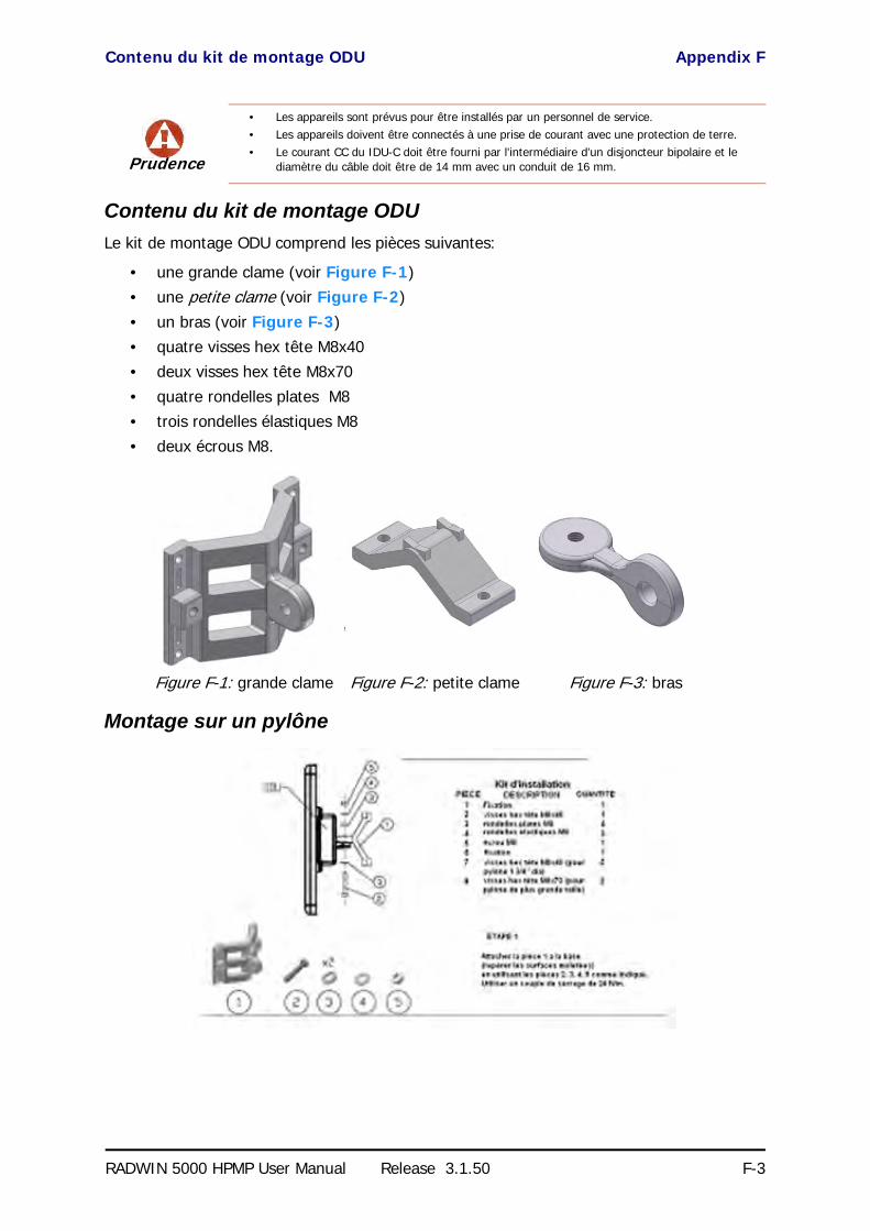
Contenu du kit de montage ODU Appendix F
RADWIN 5000 HPMP User Manual Release 3.1.50 F-3
Contenu du kit de montage ODU
Le kit de montage ODU comprend les pièces suivantes:
• une grande clame (voir Figure F-1)• une petite clame (voir Figure F-2)
• un bras (voir Figure F-3)• quatre visses hex tête M8x40• deux visses hex tête M8x70
• quatre rondelles plates M8• trois rondelles élastiques M8• deux écrous M8.
Montage sur un pylône
Prudence
• Les appareils sont prévus pour être installés par un personnel de service.• Les appareils doivent être connectés à une prise de courant avec une protection de terre.• Le courant CC du IDU-C doit être fourni par l'intermédiaire d'un disjoncteur bipolaire et le
diamètre du câble doit être de 14 mm avec un conduit de 16 mm.
Figure F-1: grande clame Figure F-2: petite clame Figure F-3: bras

Montage sur un pylône Appendix F
RADWIN 5000 HPMP User Manual Release 3.1.50 F-4
Figure F-4: Montage sur un pylône

Montage sur un mur Appendix F
RADWIN 5000 HPMP User Manual Release 3.1.50 F-5
Montage sur un mur
Figure F-5: Montage sur un mur

Montage d'une antenne externe Appendix F
RADWIN 5000 HPMP User Manual Release 3.1.50 F-6
Montage d'une antenne externe
L'antenne externe optionnelle peut être montée sur un pylône.
Contenu du kit de montage d'une antenne externe
Le kit de montage d'une antenne externe comprend les pièces suivantes
• Douze rondelles plates
• Huit rondelles élastiques• Huit écrous hex
• Quatre boulons• Un support en U• Un support à pivotement
• Deux courroies de fixation en métal
Pour installer une antenne externe sur un pylône:
1. Attacher le support en U à l'arrière de l'antenne en utilisant quatre rondelles plates, quatre rondelles élastiques et quatre écrous hex.
2. Attacher le support à pivotement au support en U en utilisant huit rondelles plates, quatre rondelles élastiques, quatre écrous hex et quatre boulons.
3. Passer les deux courroies de fixation par les fentes verticales dans le support à pivot-ement.
4. Attacher l'antenne au pylône en utilisant les deux courroies de fixation .
Ajuster l'inclinaison nécessaire en utilisant l'échelle angulaire et serrer tous les boulons et écrous à la position requise.

RADWIN 5000 HPMP User Manual Release 3.1.50 Index 1
Aaging time, HBS Bridge Mode 6-15Air Interface
Technical Specifications, general A-1Antenna Mode
MIMO and Diversity, HSU 5-21Antennas
Air rates E-3Aligning
Buzzer signals from HSU 3-12Cable, grounding 15-1Diversity Mode E-2External 3-4
Mounting 3-10Package Contents 3-4
External, Mounting 14-4MIMO - Diversity settings E-3MIMO Mode E-1Single and dual E-1
CCommunity Strings
Changing 6-12Editing 6-11MIB C-2Read-Only 6-10Read-Write 6-11Trap 6-11
Customer Support 8-14
DDC Power
terminal pinout B-2
EEvents
log 8-1
FFCC/IC DFS Considerations 13-1FEC A-1, E-3
GGSU A-5
and RFP 10-8Cascaded Sites 10-3Configuring 10-5Installation 10-4Kit 10-4Preferences 10-15Redundancy 10-3Software Update 10-16Telnet Support 10-15Transmission Phase 10-3, 10-9Tx Transmission Ratio 10-9use
functionalityscenarios 10-1
HHBS
Activation 5-7aligning HSU to 3-11Bridge Mode
aging time 6-15Configuration 6-1
Configuration with Telnet 6-40Deactivation 5-22Events Log 4-10main button menu 4-8main window 4-6Manage, Detail Panel button bar functions 4-
9manager, HSUs Panel 4-11Manager, main window 4-6package contents 3-2Package, contents of 3-2
HSSHardware Installation 9-3ODU/HSS Connection Pinout 9-6, B-1Radio Frame Pattern Table 9-6
Index

RADWIN 5000 HPMP User Manual Release3.1.50 Index 2
HSS Client 9-2Continue Transmission 9-3Disable Transmission 9-3
HSS Master 9-2HSU
aligning to HBS 3-11Button bar menu 4-13Configuration
Configuration with Telnet 6-43defined 1-2Deregistration 5-22Events Log 4-17HBS panel 4-11link performance 4-17Log on over the air 4-14Manager, context menu 4-12Manager, Link Status 4-16Manager, main button menu 4-16Manager, main window 4-15package contents 3-2Package, contents of 3-2Registration 5-17setting timeslots and MIR 5-19Status ball color codes 4-12
IInterference
caused by collocated units 9-2Inventory 6-12
LLBC
Browser warnings 16-6Calculations 16-2Climactic C Factors 16-9described 16-1Fresnel Zone, described 16-3Internal data 16-1Running 16-5User input 16-1
Lightning and Grounding Guidelines 15-1Link
Budget Calculator, see LBCInstallation
ODUMast and Wall 14-1
Login 4-3Login Errors
Incorrect IP Address 4-7Incorrect password 4-7Unsupported Device 4-6
Login showing Community Options 4-4Login showing user types 4-5Manager Software 4-2
Link Budget Calculator, see LBCLink Site
Survey 2-1
Stage 1 - Preliminary Survey 2-2Stage 2 - Physical Survey 2-3
Additional Indoor Site Requirements 2-4
Additional Outdoor Site Requirements2-3
Stage 3 - RF Survey 2-4Login Errors
Incorrect IP Address 4-7Incorrect password 4-7Unsupported Device 4-6
MManager
Preferences 4-17Manager Software
Installing 4-2main window, HBS 4-6
MIBAbout C-1Community String C-2Interface API C-1Parameters C-3Private C-2Private Parameters C-5Reference C-1Supported Variables from the RFC 1213 C-3Terminology C-1Traps C-27
OODU 3-3
Connectorized 3-4Installation, Mast and Wall 14-1Integrated Antenna 3-3Mounting Kit 14-1
PPC, Minimum Requirements 4-1Performance
Monitor 8-2PoE
Basic PoE Device 3-5, 3-5Described 3-5GbE PoE 3-5Installing a link using 3-11
ProtectionGrounding
Antenna cable 15-1ODUs 15-2
Internal ESD Protection circuits 15-7
RRadio Frame Pattern (RFP)
General Considerations 9-8General considerations 9-8

RADWIN 5000 HPMP User Manual Release3.1.50 Index 3
With HSS 9-7Without HSS 9-7
Radio LinkAdditional Tools and Materials Required 3-7Air rates E-3Connecting user equipment 3-11Hardware Installation
External Antennas 3-10Lightning protection 3-10ODU 3-9Outdoor 3-9Outdoor connections 3-10Sequence 3-8
Package Contents 3-2Package contents
External Antennas 3-4Regional Notice
French Canadian F-1
SSafety Practices iii-iv, 3-1
Grounding 3-1Preventing overexposure to RF energy 3-1
SectorConfiguration
DialogVLAN Settings
Priority number 6-8VLAN ID 6-7
Security FeaturesCommunity Strings 6-10
Editing 6-11Initial log on defaults 6-11
defined 1-2Information 8-1
Air Interface ThresholdsBBER Threshold 8-12Ethernet Thresholds - Capacity 8-12Ethernet Thresholds - Traffic 8-12RSL Threshold 8-12TSL THreshold 8-12
Performance monitoring 8-6Manager, Base Station Panel 4-8Manager, Status Panel 4-8Managing from HBS 6-1
Software UpgardeMultiple sites 11-3Single Site 11-2
Software Upgrade 11-1
TTechnical Specifications
Air Interface, general A-1Configuration A-1EMC A-4, A-4, A-5, A-6Environmental A-2Mechanical A-2
Power A-2Radio A-1Safety A-3
Telnet configuration, HSU 6-43Telnet configuration,HBS 6-40Throughput Checking 8-3Time Division Duplex 9-7typical installation 3-8
VVLAN
tagging 12-1terminology 12-1
WWiring Specifications B-1
ConnectorsUser Port B-2
LANPorts B-2
ODU-PoE Cable B-1Ports
LAN B-2User Port Connectors B-2