Radiological Instruments Tools for Protection Against ... · Radiological Instruments Tools for...
73
07/31/2002 1 Radiological Instruments Tools for Protection Against Radiation Generic Training Package for Response Teams Presented By: Paul Ares, Supervisor MEMA RIM&C Facility, Devens, MA
Transcript of Radiological Instruments Tools for Protection Against ... · Radiological Instruments Tools for...

07/31/2002 1
Radiological Instruments
Tools for
Protection Against Radiation
Generic Training Package for
Response Teams
Presented By: Paul Ares, Supervisor
MEMA RIM&C Facility, Devens, MA

2
Learning goals
Identify & Operate Survey and Contamination Meters,
Dosimeters, and Dosimeter Chargers .
Discuss their uses and limitations.
Provide proper care and maintenance of the equipment.
Identify and explain special TLD Dosimeters used for tracking
personnel exposures.
Explain the potential use of Potassium Iodide (KI) for Thyroid
protection.
Demonstrate a hands-on capability in the use of Radiological
instruments through practical exercises.

3
The CD V-777 (Modified )
Radiation Detection Set

4
1 ea. CD V-700 Survey Meter.
for measuring Low level
Gamma Exposure Rates and
some Beta detection.
1 ea. CD V-715 Survey Meter.
for measuring high level
Gamma / X-Ray Exposure Rates.
1 ea. CD V-700 Count Rate Meter
with a Special Pancake probe
for improved contamination
monitoring.
CDV-777 Modified Set Contents
Survey and Contamination Meters

5
CDV-777 Modified Set Contents (Cont’d)
Dosimetry and Potassium Iodide
6
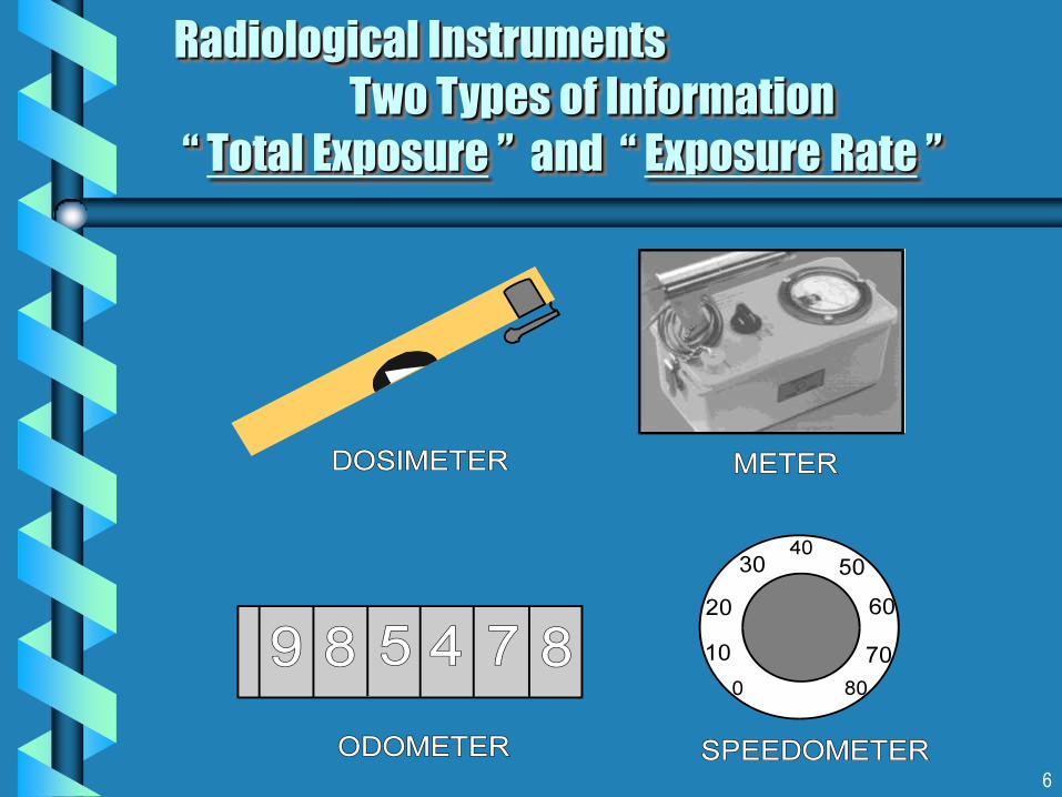
Radiological Instruments
Two Types of Information
“ Total Exposure ” and “ Exposure Rate ”

7
CD V - 700 Characteristics
Range: 0-50 mR/hr Gamma or 0-30,000 CPM Beta plus Gamma Radiation.
Visual and Audio indication of Radiation.
Used where incident exposure rates are not likely to exceed 50 mR/h.
Used in tandem with high range CD V-715 Meter.
Refer to FEMA’s Good, Some , None Table for determining response to various RAM’s.
Headphone
Jack
Operational
Check Source
Range
Selector
Switch
G-M Side Window Probe
8
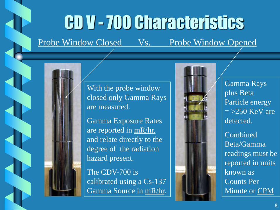
CD V - 700 Characteristics Probe Window Closed Vs. Probe Window Opened
With the probe window
closed only Gamma Rays
are measured.
Gamma Exposure Rates
are reported in mR/hr.
and relate directly to the
degree of the radiation
hazard present.
The CDV-700 is
calibrated using a Cs-137
Gamma Source in mR/hr.
Gamma Rays
plus Beta
Particle energy
= >250 KeV are
detected.
Combined
Beta/Gamma
readings must be
reported in units
known as
Counts Per
Minute or CPM

9
Standard CD V-700 Meter Face
Meter was designed to
provide linear readings in
mR/hr (Probe Closed).
Bottom of scale is marked
in non-linear units C/M
known as Counts Per Minute
CPM (Probe Open).
An alternate view of the
meter has been provided for
a more linear representation
of the CPM readings.

10
CD V-700 Meter View
Converted to read in CPM
30
60
150
120
An alternate view
of the meter has been
developed for:
A more linear
representation of
meter readings in
CPM.
Help when
performing the
Operational Check.
More accurate
Probe Open readings.

11
CD V-700 Switch Ranges
X1 Scale - 0 - . 5 mR /hr. Probe ClosedGamma Exposure Rate
OR 0 - 300 CPM Probe OpenGamma plus Beta
X10 Scale - 0 - 5 mR/hr. Probe ClosedGamma Exposure Rate
OR 0 - 3,000 CPM Probe OpenGamma plus Beta
X100 Scale - 0 - 50 mR/hr. Probe ClosedGamma Exposure Rate
OR 0 - 30,000 CPM Probe OpenGamma plus Beta

12
CDV-700 Operational Check
1. Turn OFF meter.
If you don’t you may get a
strong electrical shock.
2. Squeeze and Remove battery
retainer clips(s) to install
batteries. Check polarity.
Replace Clips.
3. Close and Latch the case and
attach headphone.
4. Remove the Probe from clip
and unwind the probe cable.

13
CD V-700 Operational Check (Cont’d)
5. Turn Selector Switch to X10. Wait 30
seconds. Open Beta window.
6. Rub your finger over the foil tape
marked “ Operational Check Source”
to locate the position of the source.
7. Place the open probe window directly
on the center of this area .
8. Move probe very slowly. Find the
highest average reading in CPM.
Compare readings with the range of
CPM listed on the calibration label.
Readings should agree.

14
CALIBRATION STATEMENT
CDV-700 VICTOREEN MOD.6A SN:LS25001712
The Massachusetts Emergency Management Agency certifies
this instrument has been calibrated on 12/20/01 and is
operable when the average reading of the instrument
check source is between 1200 - 1800 (CPM) on the X10
Scale with the probe window open.
PA
Typical
CD V-700 Calibration Label
Bar code Serial
Number of V-700
printed on the
calibration label.
Calibration date
of the CDV-700 .
Check Source
Readings in CPM
for this source at
the time of
calibration.
15
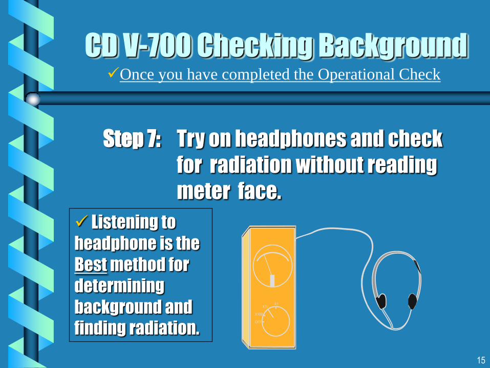
CD V-700 Checking Background
Step 7: Try on headphones and check
for radiation without reading
meter face.
Listening to
headphone is the
Best method for
determining
background and
finding radiation.
Once you have completed the Operational Check

16
Determining Background Counts Per Minute (CPM)
Set the CDV-700 range selector switch to X1.
Open the beta shield.
Ensure that a "clicking" sound is heard in headphone.
Count the clicks for fifteen (15) seconds.
Multiply the total of clicks by four (4) to determine
background Counts Per Minute (CPM).
CD V-700 Operational Check

17
for example
If total counts in fifteen seconds equal 8
8 x 4 = 32 Counts Per Minute (CPM)
Background is “32” Counts Per Minute (CPM)
Record the background CPM obtained on your
“Monitor Guide” Form 406 Rev. 7. Re-check
background every 30 minutes to eliminate errors due
to contamination of the probe or monitoring area.
CD V-700 Operational CheckDetermining Background Counts Per Minute (CPM)

18
Provides specific
instructions on how to
monitor using V-700.
Provides procedure to
monitor for thyroid
uptake, if suspected.
Use this form to record
background levels prior
to monitoring.
Log background in CPM
here >
Form 406 Rev.7
for Standard
CD V-700

19
CD V-700 Instrument Use
Performing Area Surveys
Probe may remain in handle clip and held at
waist height.
If holding probe in hand orient probe parallel
to the surface. Do not dangle probe by cord !
Always cover probe with a plastic baggie to
prevent contamination of the probe.
In areas of unknown radiation, use high- and
low-range instruments in tandem.

20
CD V-700 Instrument Use
Begin on the X1 range. If radiation goes full scale, switch
to the X10 range. If it rises again, switch to the X100
range.
Multiplying the meter readings by the range setting =
Gamma Exposure Rates in “ mR/hr” (Probe Closed) OR
Gamma plus Beta Count Rates “ CPM” (Probe Open).
If the needle peaks, earphone squeals, and needle drops,
the meter has probably been saturated (above 1-2 R/hr).
Check your High Range (CD V-715) Meter immediately !

21
C / M
mr/hr
Needle is Erratic X1 Select Average Reading
CD V-700 Practice Meter Readings
.15 X 1 = .15 mR/hr (Probe Closed)or
100 X 1 = 100 CPM (Probe Open)

22
C / M
mr/hr
CD V-700 Practice Meter Readings
.5 X 10 = 5 mR/hr (Probe Closed)or
300 X 10 = 3,000 CPM (Probe Open)
23
C / M
mr/hr
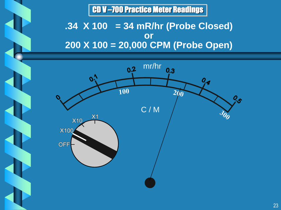
CD V –700 Practice Meter Readings
.34 X 100 = 34 mR/hr (Probe Closed)or
200 X 100 = 20,000 CPM (Probe Open)

24
CD V-700 - Performing surveys of Personnel,
Equipment or Vehicles
1. Ensure Headphone is connected.
2. Switch to the X1 Scale.
3. Open probe window.
4. Be sure to cover probe with plastic baggie.
5. Re-check background.
6. Keep probe 1 inch above surface.
7. Survey - move probe slowly atabout 1 inch / second.
8. Listen in headphone for increase in clicks or counts.
9. Suspect contamination if levels are 100 CPM or higher above background.
7
8
9

25
CD V-700 Limitations
Cannot perform operational check in a radiation
field.
Measures up to only 50 mR/hr or 30,000 CPM.
May become saturated in higher field of radiation
and act erratically.
Will not respond to all radioactive materials
commonly transported. Refer to FEMA’s Good,
Some, None Tables. (see forms pack).

26
CD V-700 Care
Perform regular operational checks.
Log results on your Quarterly Operational
Check Form (Refer to Forms Pack).
Turn meter off and remove the batteries
(for storage). Batteries will Leak !!
Place end of GM tube with wire over center of
meter (for storage). Prevents wire breakage.

27
CD V-700 Equipped With Pancake
Probe Detector
Plug-in Modification for the CD V-700 for enhanced Contamination Monitoring.
Detects * Alpha, Beta, Gamma and X-ray Contamination.
Can also be used for area monitoring.
Introduced to states by FEMA after development of the FEMA Good, Some None Table.
Two suppliers – S.E. Intl. and Canberra Aptec/NRC.

28
CD V-700 RP Switch Ranges
X1 Scale - 0 - 300 CPM
Alpha / Beta / Gamma or X-Ray
X10 Scale - 0 - 3,000 CPM
Alpha / Beta / Gamma or X-Ray
X100 Scale - 0 - 30,000 CPM
Alpha / Beta / Gamma or X-Ray

29
Connecting CD V-700 RP Probe
Switch must be “Off”.
Unwind cable from stem.
Remove CD V-700 RP probe from it’s protective Bubble Wrap Bag.
Align Pancake Probe Connector Pins with Probe Socket Holes.
Carefully attach probe to socket. Gently secure by rotating coupling to socket.
Probe Socket
Probe Connector
Pins

30
CD V-700 RP Operational CheckSpecially equipped with Pancake Probe Detector
1. Turn OFF meter. (If you don’t
you may get a strong
electrical shock) .
2. Remove battery retainer clip
to install batteries. Check
polarity. Replace Clips.
3. Close case and attach
headphone.The Lionel Model
CD V-700 uses
only 2 ea. HD “D”
Cell batteries.Note:

31
CD V-700 RP
Operational Check (cont’d)
4. Turn Range selector Switch to
X100 or X10 . Check Calibration
label for proper scale. Wait 30
seconds.
5. Remove Red Plastic Cap from
Probe and place directly on the
Operational check source .
6. Take the highest average reading
in CPM. Readings should agree
with range of CPM values listed on
the calibration label.

32
Set the CDV-700 RP range selector switch to X1.
Be sure Red Plastic Cap has been removed.
Ensure that a "clicking" sound is heard in headphone.
Count the clicks for fifteen (15) seconds.
Multiply the total of clicks by four (4) to determine
background Counts Per Minute (CPM).
CD V-700 RP Operational Check
Determining Background in Counts Per Minute (CPM)

33
for example
If total counts in fifteen seconds equals 10
10 x 4 = 40 Counts Per Minute (CPM)
Background is “40” Counts Per Minute (CPM)
Record the background CPM obtained on your “Monitor
Guide” Form 406 Rev.8 . Re-check every 30 minutes to
eliminate errors due to contamination of the probe or
monitoring area.
Background may be slightly higher for the Pancake
Detector vs. CD V-700 equipped with standard probe.
CD V-700 RP Operational CheckDetermining Background in Counts Per Minute (CPM)
34
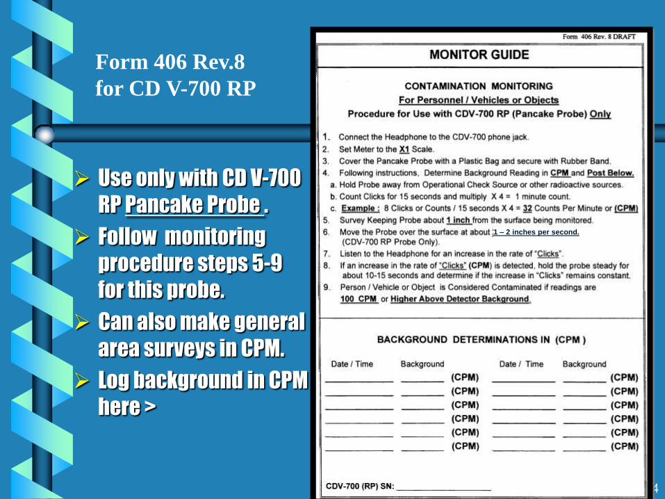
Use only with CD V-700
RP Pancake Probe .
Follow monitoring
procedure steps 5-9
for this probe.
Can also make general
area surveys in CPM.
Log background in CPM
here >
Form 406 Rev.8
for CD V-700 RP
1 – 2 inches per second.

35
Contamination Monitoring with
CD V-700 RP (Pancake Probe)
Readings must be reported in CPM .
Ensure Headphone is connected.
Switch to the X1 Scale.
Attach plastic baggie to probe.
Survey moving probe 1-2 inches per
second @ 1” above the surface.
Consider Person / Vehicle or Object
contaminated if readings are
100 CPM or greater above
background.
Probe will only detect Alphas with
Plastic Bag removed ! Increasing
risk of contamination ! Be Careful !!
7
8
9

36
CD V-715 Survey Meter

37
CD V-715 Characteristics
Range 0 - 500 R/hr
Use l High level Gamma / X -Radiation
related to:
WMD Attacks
l Backup to CD V-700 when
entering unknown radiation
environment
Industrial Accidents

38
CD V-715 Operational Check
Step 1: Turn meter off.
Step 2: Open unit, install
battery
(observe polarity).
Step 3: Turn selector switch
“ Zero ”; wait two minutes
for warm-up.

39
CD V-715 Operational Check
Step 4: Adjust needle position to "0" on meter
face. Zeroing assures accuracy.
When zeroing meter, detector does
not respond to radiation.
Step 5: Hold selector switch to Circuit
Check position to test battery
strength, proper installation, and
meter circuits. Observe a needle
deflection on meter face near or in red
area marked Circuit Check.

40
CD V-715 Operational Check
Step 6: Test operation of each range by
rotating selector switch to each
position, observing meter
deflection.
When not in radiation field, needle should not
move further than 0.3 on X100, X10, and X1
scales and 0.6 on the X0.1 scale.
41
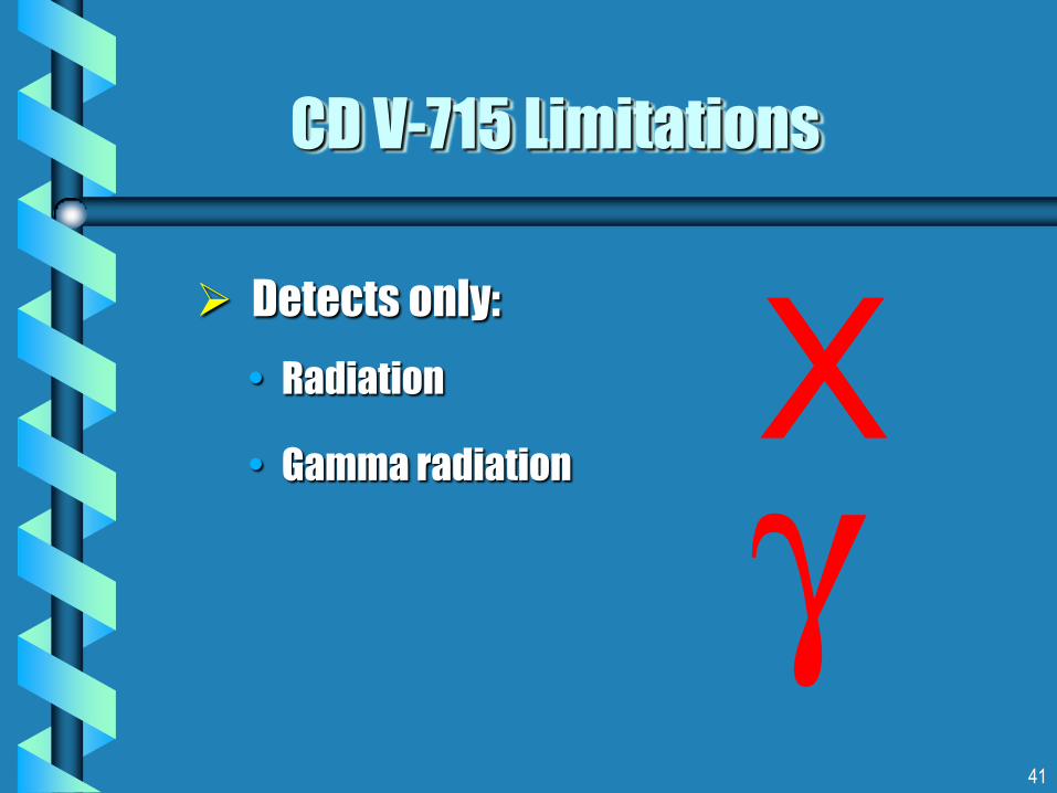
CD V-715 Limitations
Detects only:
• Radiation
• Gamma radiation

42
CD V-715 Meter Face #1

43
CD V-715 Meter Face #2

44
CD V-715 Meter Face #3

45
Three Types of Dosimeters (DRD’s) per Set
CDV-742
0-200 R
6 per Set
Used in the event
that high levels of
radiation exposure
are present .
CDV-730
0-20 R
2 Per Set
CDV-138
0-200 m R
2 Per Set
Dosimetry & Exposure Control

46
Measure Gamma and X-Radiation.
Come in varying ranges.
Provide continuous real-time
radiation exposure information.
Are worn in pairs (200 mR and 20R )
by emergency responders.
Can be re-used and transferred to
other emergency workers.
Are tested and calibrated annually
by MEMA.
Direct Reading Dosimeters
DRD’s
CD V- 730 - 20 R
CD V- 138 - 200 mR

47
1 Low Range DRD
1 Mid Range DRD
1 TLD
1 Neck Chain
1 Emergency WorkerExposure Form
1 Potassium Iodide (KI) Tablet *
* If advised by MPDH
Dosimetry Packet Contents
48
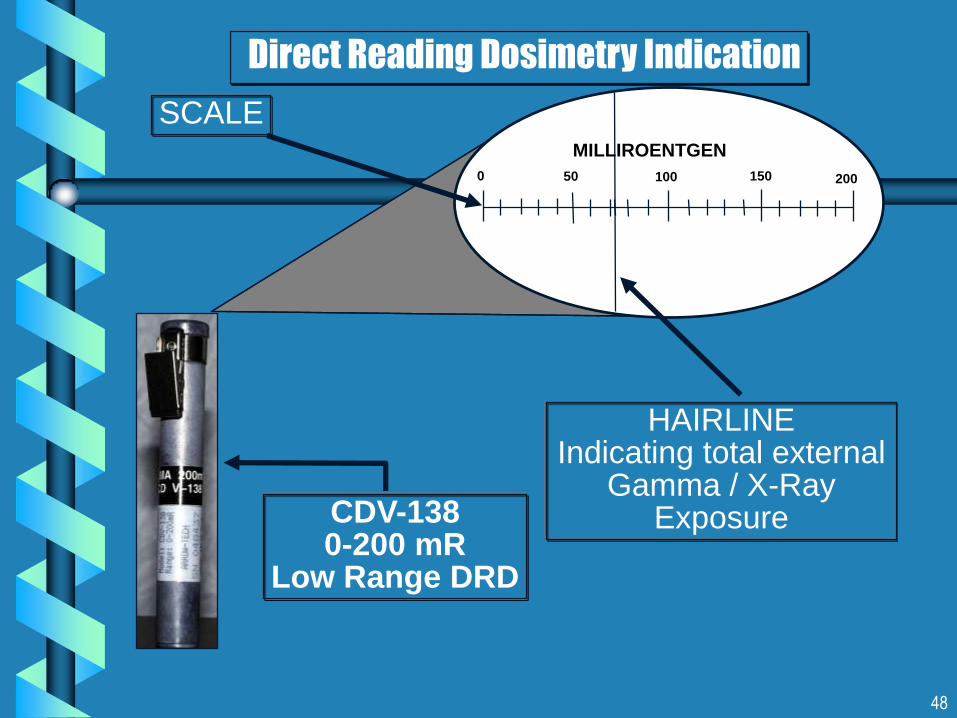
Direct Reading Dosimetry Indication
SCALE
HAIRLINEIndicating total external
Gamma / X-Ray ExposureCDV-138
0-200 mRLow Range DRD
MILLIROENTGEN
0 100 20050 150

49
Instrument: Low RangeModel: CDV-138
Scale: 0-200 mR
Initial Reading :0 mR
Final Reading: 50 mR
Total Dose: 50 mR
Reading the Direct Reading Dosimeter
MILLIROENTGEN
0 100 200
MILLIROENTGEN
0 100 200
50 150
50
50

50
Reading the Direct Reading Dosimeter
ROENTGENS
0 10 20
ROENTGENS
0 10 20
Instrument: Mid RangeModel: CDV-730
Scale: 0-20R
Initial Reading: 0 R
Final Reading: 3 R
Total Dose: 3 R
155
5 15

51
Instrument:__________
Scale:__________
Initial Reading:_________
MILLIROENTGEN
0 100 20020 40 60 80 120 140 160 180
MILLIROENTGEN
0 100 20020 40 60 80 120 140 160 180
Total Dose: ______
Final Reading: _____
Reading the Direct Reading Dosimeter

52
ROENTGENS
0 10 20
ROENTGENS
0 10 20
Instrument:__________
Scale: __________
Initial Reading
__________
Total Dose: _______
Final Reading:______5
5 15
Reading the Direct Reading Dosimeter

53
Charging Contact
Dosimeter
Zero
Adjust
Knob
Case Fastener
Cap and Chain
CD V-750 Dosimeter Charger
HD
“D”
Cell

54
CD V-750 Preparation for Use
Step 1: Install one D cell battery.
Remove center screw and open unit.
Observe polarity.
Insert the Battery.
Close Case.
Hand tighten center screw.

55
Step 2: Remove cap, top left corner.
Press dosimeter FIRMLY onto
charging contact .
Step 3: Turn zero knob until dosimeter
meter reads “0”.
Step 4: Remove Dosimeter from Charger
and check setting. hold up to a
light source – Not on the charger.
CD V-750 Preparation for Use
56
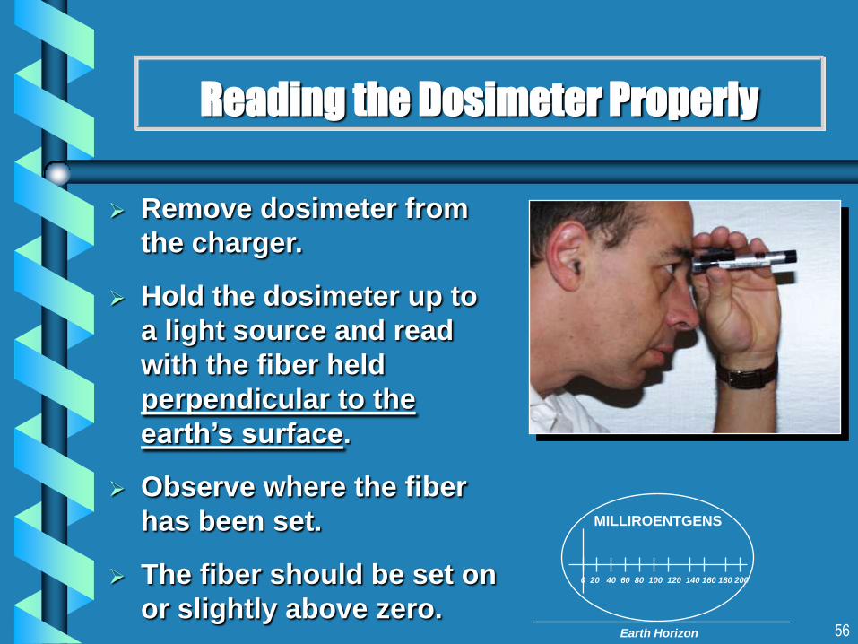
Reading the Dosimeter Properly
Remove dosimeter from
the charger.
Hold the dosimeter up to
a light source and read
with the fiber held
perpendicular to the
earth’s surface.
Observe where the fiber
has been set.
The fiber should be set on
or slightly above zero.
MILLIROENTGENS
0 20 40 60 80 100 120 140 160 180 200
Earth Horizon
57
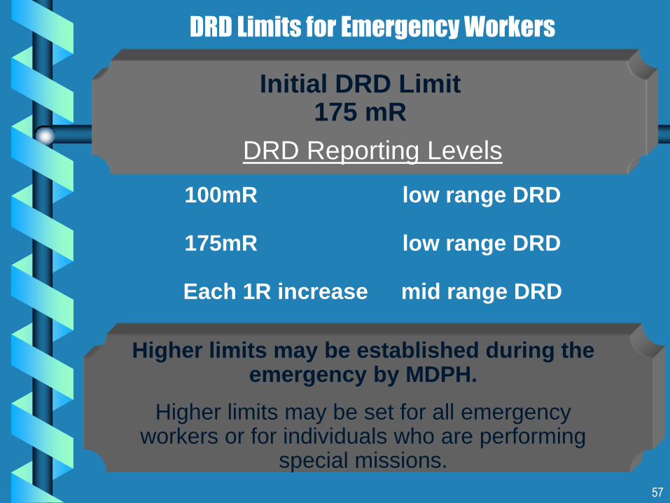
DRD Limits for Emergency Workers
DRD Reporting Levels
100mR low range DRD
175mR low range DRD
Each 1R increase mid range DRD
Initial DRD Limit175 mR
Higher limits may be established during the emergency by MDPH.
Higher limits may be set for all emergency workers or for individuals who are performing
special missions.
58
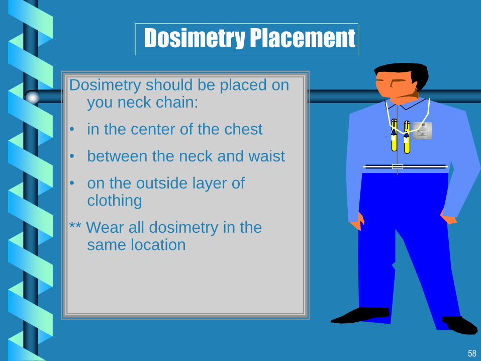
Dosimetry Placement
Dosimetry should be placed on you neck chain:
• in the center of the chest
• between the neck and waist
• on the outside layer of clothing
** Wear all dosimetry in the same location
D V-7025462
CD
D V-7025462
CD

59
Thermo – Luminescent
Dosimeters ( TLD’s)

60
Thermo Luminescent Dosimeters ( TLD’s)
Provides the Permanent Legal Record of an individuals Radiation Exposure.
Passively and Continuously Measures Beta and Gamma Radiation Exposures.
Are Very Accurate Typically ( 10mR – KRem)
Cannot be read in the field by Emergency Workers. Must be exchanged annually and are sent to a lab for analysis.
Are identical to the TLD’s used by Emergency Workers in the Pilgrim EPZ..

61
Every CDV-777 Set Contains :
6 ea. Whole Body Wallet TLD’s
and 1 ea. Control TLD .
Plan is to issue 2 ea. TLD’s Per
shift x 3 shifts for 24 hour
coverage.
Can issue all 6 TLD’s for larger
staffing if emergency
warrants.

62
Landauer Wallet TLD
(Front View)
Donned by Emergency Workers along with DRD’s.
Must Clip to TLD and place on neck chain.
Once issued - Are not transferable to other emergency workers.
Must be returned to MEMA for annual exchange.
Anneal or
Start Date TLD Serial
Number
63
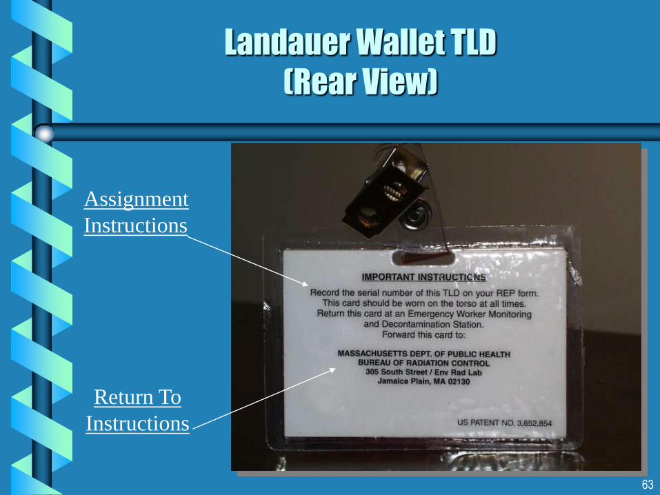
Landauer Wallet TLD
(Rear View)
Assignment
Instructions
Return To
Instructions
64
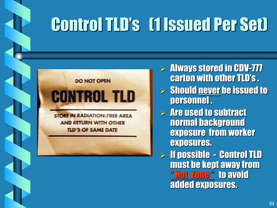
Control TLD’s (1 Issued Per Set)
Always stored in CDV-777 carton with other TLD’s .
Should never be issued to personnel .
Are used to subtract normal background exposure from worker exposures.
If possible - Control TLD must be kept away from “ Hot Zone ” to avoid added exposures.

65
Potassium Iodide (KI)
3 day supply for 6 emergency workers
KI protects only the
Thyroid Gland from the
uptake of Radioactive
Iodine 131 .
2 Btls./CDV-777 Set.
14 ea. 130 mg Tablets
per Bottle.
Only take if advised by
MDPH.
Read enclosed
advisory for possible
side effects.
Dose is 1 Tablet / Day for 10 days
66
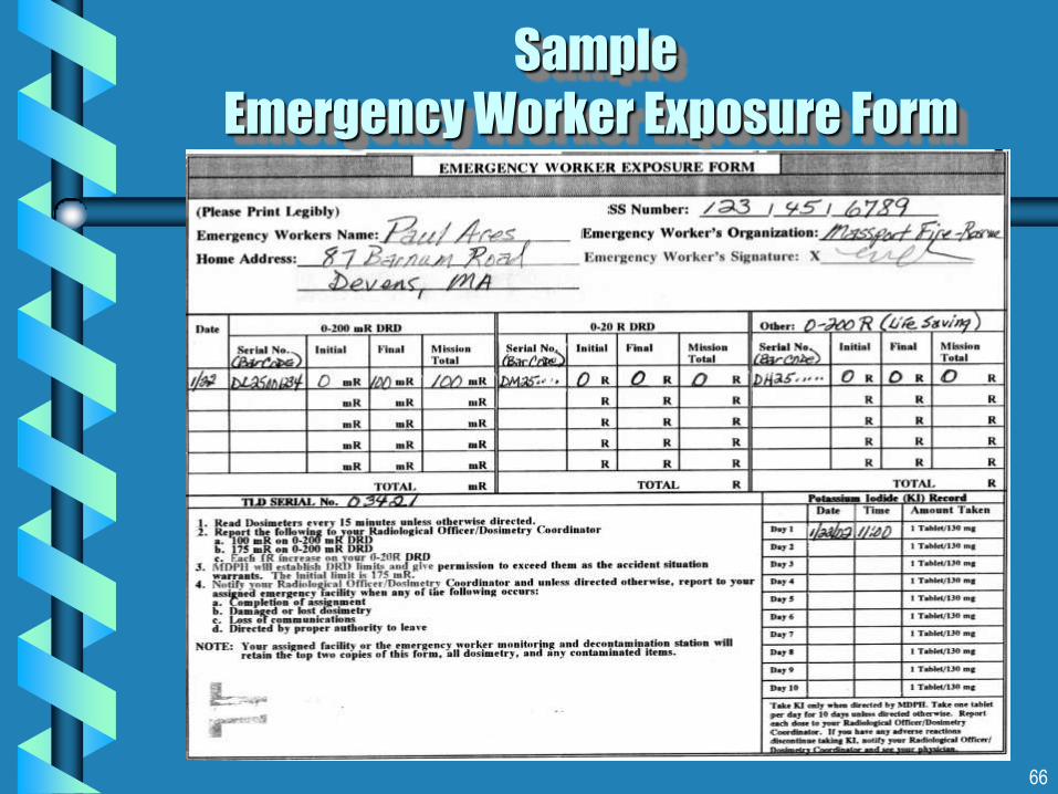
Sample
Emergency Worker Exposure Form

67
Instrumentation Exercise # 1
Working in Teams of 2
Using Both Standard and Pancake CDV-700 Meters
1. There are three small sources to measure using both meters.
2. Start on the X1 Scale.
3. Place probe(s) on the the surface of the paper(s) , record readings CPM or mR/hr on your form.
4. With the standard V-700 take readings with probe open and closed.
5. Take the same series of readings using the CDV-700 with Pancake Detector.
Points to
Remember ! !
Probe Open
readings will be
in CPM .
Probe Closed
readings will be
mR/hr.
Pancake Probe
readings are
reported in CPM.

68
Using the Std. CDV-700 Probe Open - X1approach the package containing RAM’s. Note increase in background as you near.
Identify the Radioactive Labels on package.
ID RAM contained in this package. What are acceptable radiation levels for this package @ surface and 1 meter ?
Measure radiation levels on contact and @ 1 Meter from the package.
Should the CDV-700 Probe be Closed or Opened to determine if package is still intact or damaged ?
Take same set of readings using a CD V-700 equipped with a Pancake. How do readings compare with Standard CD V-700 ?
There may be a second source nearby. Can you locate it using the Pancake ?
Instrumentation Exercise # 2
Using both CDV-700’s for
Response to a Transportation Accident
69
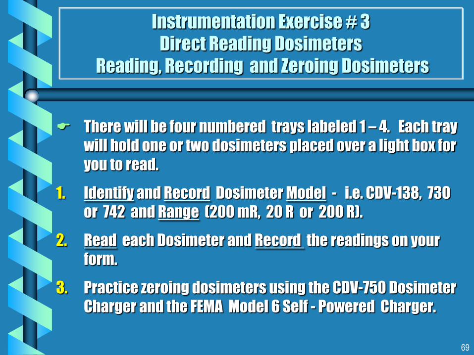
There will be four numbered trays labeled 1 – 4. Each tray
will hold one or two dosimeters placed over a light box for
you to read.
1. Identify and Record Dosimeter Model - i.e. CDV-138, 730
or 742 and Range (200 mR, 20 R or 200 R).
2. Read each Dosimeter and Record the readings on your
form.
3. Practice zeroing dosimeters using the CDV-750 Dosimeter
Charger and the FEMA Model 6 Self - Powered Charger.
Instrumentation Exercise # 3
Direct Reading Dosimeters
Reading, Recording and Zeroing Dosimeters
70
Exercise Review Q& A’s Exercise
# 1
1. Based on your readings - What kind of RAM’s ( Alpha, Beta, Gamma ) were used for source readings 1, 2 and 3 ?
2. Were both CDV-700’s capable of detecting these sources ?
3. Which of the CDV-700’s do you think is better suited for detecting the presence of unknown types of RAM contamination in the environment.
4. Which of the CDV-700’s is better suited to measuring the degree of Gamma radiation hazard in milliRoentgens/Hr or mR/Hr.
71
Exercise # 2
1. Which of the two CDV-700’s is the appropriate meter for determining if a package has been labeled properly ? Why ?
2. What was the maximum surface reading in mR/hr.obtained from the package of RAM ?
3. Based on your readings - Do you think this package meets packaging regulations ?
Exercise Review Q& A’s (con’t)

72
Exercise # 3
1. What Dosimeter Model (s) were placed in tray s # 1, 2, 3, 4 ?
2. What was the range or scale of these dosimeters ?
3. What did these dosimeters read ?
Exercise Review Q& A’s (con’t)

73
Annual Instrument
Service
Contact the MEMA RIM&C Facility for repairs, annual
instrument calibration, exchange of TLD’s and KI at:
Massachusetts Emergency Management Agency
Maintenance & Calibration Facility
87 Barnum Rd., Bldg. T-3710 (MANG)
Devens, MA 01432-3524
Tel: 978-772-3122 Fax: 978-772-4111 email: [email protected]


