Radiocommunication Study Groups - IEEE Standards ... · Web viewThe system operating in the other...
200
Radiocommunication Study Groups THIRD MEETING OF WORKING PARTY 5D SEOUL, KOREA, 8-15 October 2008 Source: Revision 1 to Document 5D/TEMP/127 24 October 2008 English only Working Party 5D LIAISON STATEMENT TO EXTERNAL ORGANIZATIONS REQUEST FOR INFORMATION FOR RECOMMENDATIONS ITU-R M.1580 AND M.1581 (UNWANTED EMISSION CHARACTERISTICS) 1 Introduction At the Seoul meeting of ITU-R Working Party (WP) 5D the work on revision 3 of Recommendations ITU-R M.1580 and M.1581 continued with a view to finalize the revisions at the 4 th meeting of ITU-R WP 5D (10 - 17 February 2009). Amongst other issues, some parameters have been discussed extensively within ITU-R WP 5D. WP 5D came to a common understanding that it will try to harmonize all 6 annexes to the maximum extent possible with regard to the parameters contained therein, while keeping the current scope of Recommendations ITU-R M.1580 and M.1581. /home/website/convert/temp/convert_html/5af199e27f8b9ac2468f8704/document.doc 26.11.08 24.10.08 1 2 3 4 5 6 7 8 9 10 11 1
Transcript of Radiocommunication Study Groups - IEEE Standards ... · Web viewThe system operating in the other...

Radiocommunication Study Groups
THIRD MEETING OF WORKING PARTY 5DSEOUL, KOREA, 8-15 October 2008
Source: Revision 1 to Document 5D/TEMP/12724 October 2008English only
Working Party 5D
LIAISON STATEMENT TO EXTERNAL ORGANIZATIONS
REQUEST FOR INFORMATION FOR RECOMMENDATIONS ITU-R M.1580 AND M.1581 (UNWANTED EMISSION CHARACTERISTICS)
1 Introduction
At the Seoul meeting of ITU-R Working Party (WP) 5D the work on revision 3 of Recommendations ITU-R M.1580 and M.1581 continued with a view to finalize the revisions at the 4th meeting of ITU-R WP 5D (10 - 17 February 2009).
Amongst other issues, some parameters have been discussed extensively within ITU-R WP 5D. WP 5D came to a common understanding that it will try to harmonize all 6 annexes to the maximum extent possible with regard to the parameters contained therein, while keeping the current scope of Recommendations ITU-R M.1580 and M.1581.
2 Parameters
2.1 Test Tolerance1
As part of the above mentioned discussions, “test tolerances” have been addressed as an issue in relation to the harmonized content of these Recommendations and how “test tolerances” may have been accounted for in the provided parameters.
Hence ITU-R WP 5D kindly requests external organisations to provide test tolerance information as implemented in their specifications for the parameters provided for inclusion in Recommendations ITU-R M.1580 and M.1581.
ITU-R WP 5D will note which principle described in Recommendation ITU-R M.1545 has been used for each annex, considering the responses from the external organizations.
1 Remark: With reference to Recommendation ITU-R M.1545, “test tolerance” is the relaxation value referred to in recommends 2 of Recommendation ITU-R M.1545, i.e. the difference between the core specification value and the test limit, evaluated applying the shared risk principle as per Figures 2 and 3 of Annex 1 of Recommendation ITU-R M.1545. In case the core specification value is equal to the test limit (Figure 3 of Annex 1 of Recommendation ITU-R M.1545) the “test tolerances” are equal to 0.
/tt/file_convert/5af199e27f8b9ac2468f8704/document.doc 26.11.08 24.10.08
1
234
5678
9
10
111213
141516
1718
12345
6
- -
2.2 ACLR
In the view of ITU-R WP 5D, “ACLR” is considered to be one of the relevant parameters to be included in Recommendations ITU-R M.1580 and M.1581. Analysing the 6 annexes of Recommendations ITU-R M.1580 and M.1581, ITU-R WP 5D came to the conclusion that currently not all annexes include this parameter.
Hence ITU-R WP 5D kindly requests external organizations to provide intra-system and, where available, inter-system ACLR values for their RTT. To have a clear understanding, it is requested to also provide the definition of ACLR used, including all assumptions used in deriving these values. It should be noted that it is not intended to make the “ACLR” parameter a mandatory regulatory obligation, as it is up to the administrations which part of a Recommendation they want to use in national regulations.
3 Request for submission of information
To ensure the finalization of the draft revision of Recommendations ITU-R M.1580-2 and M.1581-2 at the 4th meeting of ITU-R WP 5D (10-17.Feb.2009), ITU-R WP 5D kindly requests exrternal organizations to provide the above mentioned parameters along with relevant information where:(a) they are not already part of Recommendations ITU-R M.1580 and M.1581; and/or (b) new /additional values should be implemented in Recommendations ITU-R M.1580 and M.1581.
For convenience the latest working draft of the revised Recommendations are attached electronically (Source Documents TEMP/128(Rev.1) and TEMP/129(Rev.1)) so that the specific questions above may be answered.
ITU-R WP 5D thanks external organizations for their collaboration.
Status: For response
Deadline: 1600 hours UTC, 3 Febuary 2009
Contact: Colin LangtryCounsellor, ITU-R SG 5
Tel: +41 22 730 6178Email: [email protected]
/TT/FILE_CONVERT/5AF199E27F8B9AC2468F8704/DOCUMENT.DOC 08/05/2023 08/05/2023
21
1
2345
6789
1011
12
13141516171819
202122
2324
252627
28
2
Source: Revision 1 to Document 5D/TEMP/128
Attachment 1
WORKING DOCUMENT TOWARDS THEA DRAFT REVISIONED OF RECOMMENDATION ITU-R M.1580-2*
Generic unwanted emission characteristics of base stations using the terrestrial radio interfaces of IMT-2000
(QUESTION ITU-R 229/8)(2002-2005-2007)
Scope
This Recommendation provides the generic unwanted emission characteristics of base stations using the terrestrial radio interfaces of IMT-2000.
The ITU Radiocommunication Assembly,
considering
a) that unwanted emissions consist of both spurious and out-of-band (OoB) emissions according to No. 1.146 of the Radio Regulation (RR) and that spurious and OoB emissions are defined in RR Nos. 1.145 and 1.144, respectively;
b) that limitation of the maximum permitted levels of unwanted emissions of IMT-2000 base stations (BS) is necessary to protect other radio systems and services from interference and to enable coexistence between different technologies;
c) that too stringent limits may lead to an increase in complexity of IMT-2000 BS;
d) that every effort should be made to keep limits for unwanted emissions at the lowest possible values taking account of economic factors and technological limitations;
e) that Recommendation ITU-R SM.329 relates to the effects, measurements and limits to be applied to spurious domain emissions;
f) that the same spurious emission limits apply equally to BS of all radio interfaces;
g) that Recommendation ITU-R SM.1541 relating to OoB emission specifies generic limits in the OoB domain which generally constitute the least restrictive OoB emission limits and encourages the development of more specific limits for each system;
h) that the levels of spurious emissions of IMT-2000 BS shall comply with the limits specified in RR Appendix 3;
j) that the harmonization of unwanted emission limits will facilitate global use and access to a global market; however national/regional variations in unwanted emission limits may exist;
* This Recommendation should be brought to the attention of Radiocommunication Study Group 1.Attention: The information contained in this document is temporary in nature and does not necessarily represent material that has been agreed by the group concerned. Since the material may be subject to revision during the meeting, caution should be exercised in using the document for the development of any further contribution on the subject./TT/FILE_CONVERT/5AF199E27F8B9AC2468F8704/DOCUMENT.DOC 08/05/2023 08/05/2023
1
2
34
5
6
789
101112
13
1415
1617
18
192021
2223
2425
12345
k) that additional work is needed in order to define unwanted emission limits for equipment operating in the other bands identified for IMT-2000 at the World Radiocommunication Conference (Istanbul, 2000) (WRC-2000);
l) that unwanted emission limits are dependent on the transmitter emission characteristics, ITU spurious emission limits and national standards and regulations in addition to depending on services operating in other bands,
noting
a) the work carried out by standardization bodies to define limits to protect other radio systems and services from interference and to enable coexistence between different technologies;
b) that IMT-2000 base stations must comply with local, regional, and international regulations for out-of-band and spurious emissions relevant to their operations, wherever such regulations apply;
c) with regard to Annex 6, IMT-2000 OFDMA TDD WMAN, additional urgent work, in particular on emission mask and ACLR, is needed to ensure geographical coexistence with other IMT-2000 radio interfaces,
recommends
1 that the unwanted emission characteristics of IMT-2000 base stations should be based on the limits contained in the technology specific Annexes 1 to 6 which correspond to the radio interface specifications described in § 5.1 to 5.6 of Recommendation ITU-R M.1457.
NOTE 1 – Except the cases stated in Note 2, Note 3, Note 4 and Note 54, the unwanted emission limits are defined for BS operating according to the following arrangement: frequency division duplex (FDD) uplink in the band 1 920-1 980 MHz, FDD downlink in the band 2 110-2 170 MHz and time division duplex (TDD) in the band 1 885-1 980 MHz and 2 010-2 025 MHz. Future versions of this Recommendation will include limits applicable to other frequency bands. Subject to further study, it is anticipated that such limits would be similar to those already contained in this Recommendation.
NOTE 2 – The unwanted emission limits defined in Annex 1 are for BS operating one of ,or a combination of, the following arrangements:– Frequency division duplex (FDD) uplink in the band 1 920-1 980 MHz, FDD downlink in
the band 2 110-2 170 MHz, in Annex 1 referred to as FDD Band I in UTRA or Band 1 in E-UTRA.
– FDD uplink in the band 1 850-1 910 MHz, FDD downlink in the band 1 930-1 990 MHz, in Annex 1 referred to as FDD Band II in UTRA or Band 2 in E-UTRA.
– FDD uplink in the band 1 710-1 785 MHz, FDD downlink in the band 1 805-1 880 MHz, in Annex 1 referred to as FDD Band III in UTRA or Band 3 in E-UTRA.
– FDD uplink in the band 1 710-1 755 MHz, FDD downlink in the band 2 110-2 155 MHz, in Annex 1 referred to as FDD Band IV in UTRA or Band 4 in E-UTRA.
– FDD uplink in the band 824- 849 MHz, FDD downlink in the band 869-894 MHz, in Annex 1 referred to as FDD Band V in UTRA or Band 5 in E-UTRA.
– FDD uplink in the band 830- 840 MHz, FDD downlink in the band 875- 885 MHz, in Annex 1 referred to as FDD Band VI in UTRA or Band 6 in E-UTRA.
– FDD uplink in the band 2 500-2 570 MHz, FDD downlink in the band 2 620-2 690 MHz, in Annex 1 referred to as FDD Band VII in UTRA or Band 7 in E-UTRA.
/TT/FILE_CONVERT/5AF199E27F8B9AC2468F8704/DOCUMENT.DOC 08/05/2023 08/05/2023
1
123
456
7
89
101112
131415
16
171819
20212223242526
2728293031323334353637383940414243
2

– FDD uplink in the band 880-915 MHz, FDD downlink in the band 925-960 MHz, in Annex 1 referred to as FDD Band VIII in UTRA or Band 8 in E-UTRA.
– FDD uplink in the band 1 749.9-1 784.9 MHz, FDD downlink in the band 1 844.9-1 879.9 MHz, in Annex 1 to referred as FDD Band IX in UTRA or Band 9 in E-UTRA.
– FDD uplink in the band 1 710-1 770 MHz, FDD downlink in the band 2 110-2 170 MHz, in Annex 1 referred to as FDD Band X in UTRA or Band 10 in E-UTRA.
– FDD uplink in the band 1 427.9-1 452.9 MHz, FDD downlink in the band 1 475.9-1 500.9 MHz, in Annex 1 referred to as FDD Band XI in UTRA or Band 11 in E-UTRA.
– FDD uplink in the band 698-716 MHz, FDD downlink in the band 728-746 MHz, in Annex 1 referred to as FDD Band XII in UTRA or Band 12 in E-UTRA.
– FDD uplink in the band 777-787 MHz, FDD downlink in the band 746-756 MHz, in Annex 1 referred to as FDD Band XIII in UTRA or Band 13 in E-UTRA.
– FDD uplink in the band 788-798 MHz, FDD downlink in the band 758-768 MHz, in Annex 1 referred to as FDD Band XIV in UTRA or Band 14 in E-UTRA.
Future versions of this Recommendation will include limits applicable to other frequency bands. Subject to further study, it is anticipated that such limits would be similar to those already contained in this Recommendation.
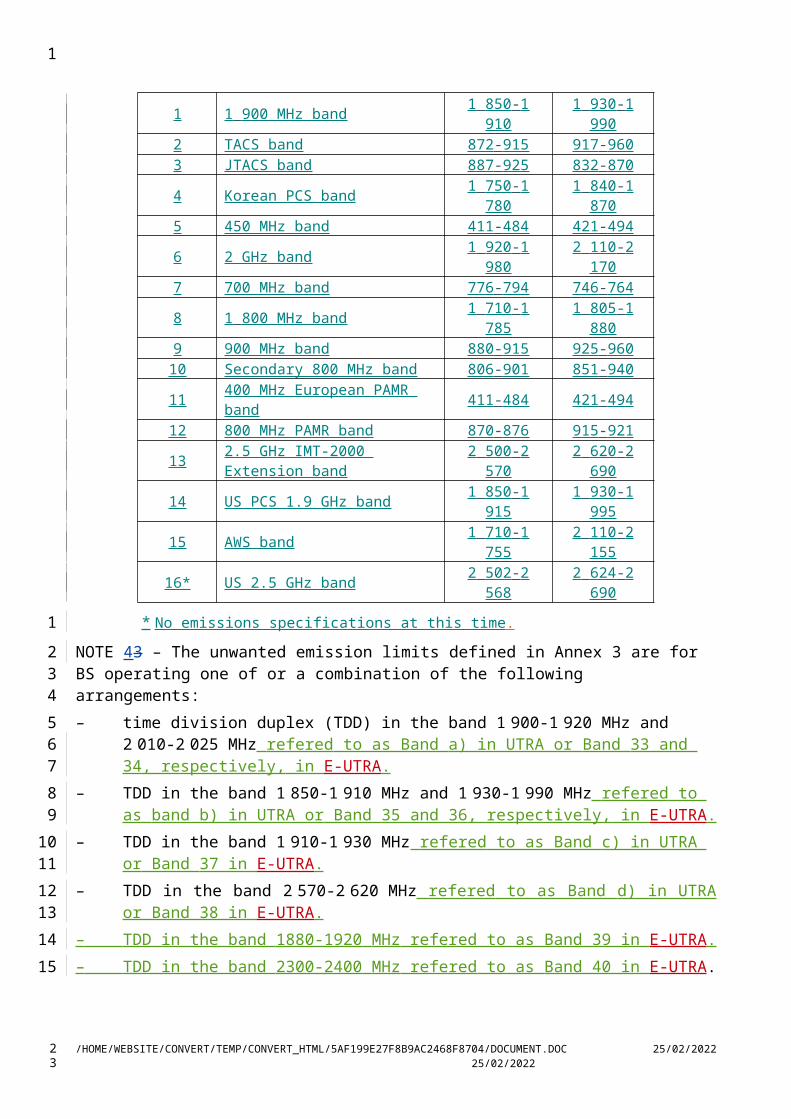
NOTE 3 – The unwanted emission limits defined in Annex 2 are for BS operating in the following arrangements and apply to both cdma2000 and HRPD operating modes except as noted:
Band Class Name
MS Transmit Frequency
(MHz)
BS Transmit Frequency
(MHz)0 800 MHz band 824-849 869-8941 1 900 MHz band 1 850-1 910 1 930-1 9902 TACS band 872-915 917-9603 JTACS band 887-925 832-8704 Korean PCS band 1 750-1 780 1 840-1 8705 450 MHz band 411-484 421-4946 2 GHz band 1 920-1 980 2 110-2 1707 700 MHz band 776-794 746-7648 1 800 MHz band 1 710-1 785 1 805-1 8809 900 MHz band 880-915 925-960
10 Secondary 800 MHz band 806-901 851-94011 400 MHz European PAMR band 411-484 421-49412 800 MHz PAMR band 870-876 915-92113 2.5 GHz IMT-2000 Extension band 2 500-2 570 2 620-2 69014 US PCS 1.9 GHz band 1 850-1 915 1 930-1 99515 AWS band 1 710-1 755 2 110-2 15516* US 2.5 GHz band 2 502-2 568 2 624-2 690
* No emissions specifications at this time.
NOTE 43 – The unwanted emission limits defined in Annex 3 are for BS operating one of or a combination of the following arrangements:– time division duplex (TDD) in the band 1 900-1 920 MHz and 2 010-2 025 MHz refered to as
Band a) in UTRA or Band 33 and 34, respectively, in E-UTRA.– TDD in the band 1 850-1 910 MHz and 1 930-1 990 MHz refered to as band b) in UTRA or
Band 35 and 36, respectively, in E-UTRA.
/TT/FILE_CONVERT/5AF199E27F8B9AC2468F8704/DOCUMENT.DOC 08/05/2023 08/05/2023
1
123456789
1011121314
151617
1819
20
21
222324252627
2

– TDD in the band 1 910-1 930 MHz refered to as Band c) in UTRA or Band 37 in E-UTRA.– TDD in the band 2 570-2 620 MHz refered to as Band d) in UTRA or Band 38 in E-UTRA.– TDD in the band 1880-1920 MHz refered to as Band 39 in E-UTRA.– TDD in the band 2300-2400 MHz refered to as Band 40 in E-UTRA.Future versions of this Recommendation will include limits applicable to other frequency bands. Subject to further study, it is anticipated that such limits would be similar to those already contained in this Recommendation.
NOTE 54 – The unwanted emission limits defined in Annex 6 are for BS operating in the following arrangement:– TDD in the band 2 300-2 400 MHz;– TDD in the band 2 500-2 690 MHz;– TDD in the band 3 400-3 600 MHz.
Annex 1 – IMT-2000 code division multiple access (CDMA) direct spread (universal terrestrial radio access (UTRA) FDD) base stations
Annex 2 – IMT-2000 CDMA multi-carrier (cdma-2000) base stations
Annex 3 – IMT-2000 CDMA TDD (UTRA TDD) base stations
Annex 4 – IMT-2000 time division multiple access (TDMA) single-carrier (UWC-136) base stations
Annex 5 – IMT-2000 frequency division multiple access (FDMA)/TDMA (digital enhanced cordless telecommunications (DECT)) base stations
Annex 6 – IMT-2000 OFDMA TDD WMAN base stations.
Appendix 1 – Definitions and Abbreviations
/TT/FILE_CONVERT/5AF199E27F8B9AC2468F8704/DOCUMENT.DOC 08/05/2023 08/05/2023
1
1234
567
89
101112
13
1415
16
17
1819
2021
22
23
2425
2

Annex 1
IMT-2000 (code division multiple access (CDMA) direct spread (universal terrestrial radio access (UTRA) FDD) base stations
1 Measurement uncertainty
Values specified in this Annex differ from those specified in Recommendation ITU-R M.1457 since values in this Annex incorporate test tolerances defined in Recommendation ITU-R M.1545.
2 Spectrum mask
2.1 UTRA spectrum mask
The mask defined in Tables 1 to 4 below may be mandatory in certain regions. In other regions this mask may not be applied.
For regions where this clause applies, the requirement should be met by a BS transmitting on a single radio frequency (RF) carrier configured in accordance with the manufacturer’s specification. Emissions should not exceed the maximum level specified in Tables 1 to 4 for the appropriate BS maximum output power, in the frequency range from f 2.5 MHz to fmax from the carrier frequency, where:– f is the separation between the carrier frequency and the nominal –3 dB point of the
measuring filter closest to the carrier frequency.– f_offset is the separation between the carrier frequency and the centre of the measurement
filter:– f_offsetmax is either 12.5 MHz or the offset to the BS transmit band edge, whichever is
the greater.– fmax is equal to f_offsetmax minus half of the bandwidth of the measuring filter.
/TT/FILE_CONVERT/5AF199E27F8B9AC2468F8704/DOCUMENT.DOC 08/05/2023 08/05/2023
1
1234
5
67
8
9
1011
121314151617181920212223
2
- 8 -
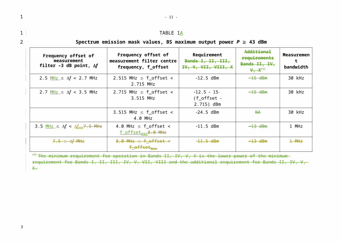
TABLE 1A
Spectrum emission mask values, BS maximum output power P 43 dBm
Frequency offset of measurementfilter –3 dB point, f
Frequency offset of measurement filter centre frequency, f_offset
RequirementBands I, II, III, IV, V, VII,
VIII, X
Additional requirements
Bands II, IV, V, X(1)
Measurement bandwidth
2.5 MHz f 2.7 MHz 2.515 MHz f_offset 2.715 MHz 12.5 dBm −15 dBm 30 kHz2.7 MHz f 3.5 MHz 2.715 MHz f_offset 3.515 MHz 12.5 15
(f_offset 2.715) dBm−15 dBm 30 kHz
3.515 MHz f_offset 4.0 MHz 24.5 dBm NA 30 kHz3.5 MHz f fmax7.5 MHz 4.0 MHz f_offset
f_offsetmax8.0 MHz11.5 dBm −13 dBm 1 MHz
7.5 f MHz 8.0 MHz f_offset f_offsetmax 11.5 dBm −13 dBm 1 MHz(1) The minimum requirement for operation in Bands II, IV, V, X is the lower power of the minimum requirement for Bands I, II, III, IV, V, VII, VIII and the additional requirement for Bands II, IV, V, X.
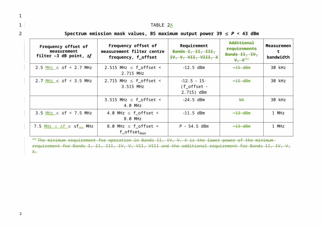
TABLE 2A
Spectrum emission mask values, BS maximum output power 39 P < 43 dBm
Frequency offset of measurementfilter –3 dB point, f
Frequency offset of measurement filter centre frequency, f_offset
RequirementBands I, II, III, IV, V, VII,
VIII, X
Additional requirements
Bands II, IV, V, X(1)
Measurement bandwidth
2.5 MHz f < 2.7 MHz 2.515 MHz f_offset < 2.715 MHz 12.5 dBm −15 dBm 30 kHz2.7 MHz f < 3.5 MHz 2.715 MHz f_offset < 3.515 MHz 12.5 15
(f_offset 2.715) dBm−15 dBm 30 kHz
3.515 MHz f_offset < 4.0 MHz 24.5 dBm NA 30 kHz3.5 MHz f < 7.5 MHz 4.0 MHz f_offset < 8.0 MHz 11.5 dBm −13 dBm 1 MHz
7.5 MHz f fmax MHz 8.0 MHz f_offset < f_offsetmax P 54.5 dBm −13 dBm 1 MHz(1) The minimum requirement for operation in Bands II, IV, V, X is the lower power of the minimum requirement for Bands I, II, III, IV, V, VII, VIII and the additional requirement for Bands II, IV, V, X.
1
1
2
3
4
3

TABLE 3A
Spectrum emission mask values, BS maximum output power 31 P < 39 dBm
Frequency offset of measurement
filter –3 dB point, f
Frequency offset of measurement filter centre frequency, f_offset
RequirementBands I, II, III, IV, V, VII,
VIII, X
Additional requirements
Bands II, IV, V, X(1)
Measurement bandwidth
2.5 MHz f < 2.7 MHz 2.515 MHz f_offset < 2.715 MHz P – 51.5 dBm −15 dBm 30 kHz2.7 MHz f < 3.5 MHz 2.715 MHz f_offset < 3.515 MHz P – 51.5 15
(f_offset 2.715) dBm−15 dBm 30 kHz
3.515 MHz f_offset < 4.0 MHz P – 63.5 dBm NA 30 kHz3.5 MHz f < 7.5 MHz 4.0 MHz f_offset < 8.0 MHz P – 50.5 dBm −13 dBm 1 MHz
7.5 MHz f fmax MHz 8.0 MHz f_offset < f_offsetmax P – 54.5 dBm −13 dBm 1 MHz
(1) The minimum requirement for operation in Bands II, IV, V, X is the lower power of the minimum requirement for Bands I, II, III, IV, V, VII, VIII and the additional requirement for Bands II, IV, V, X.
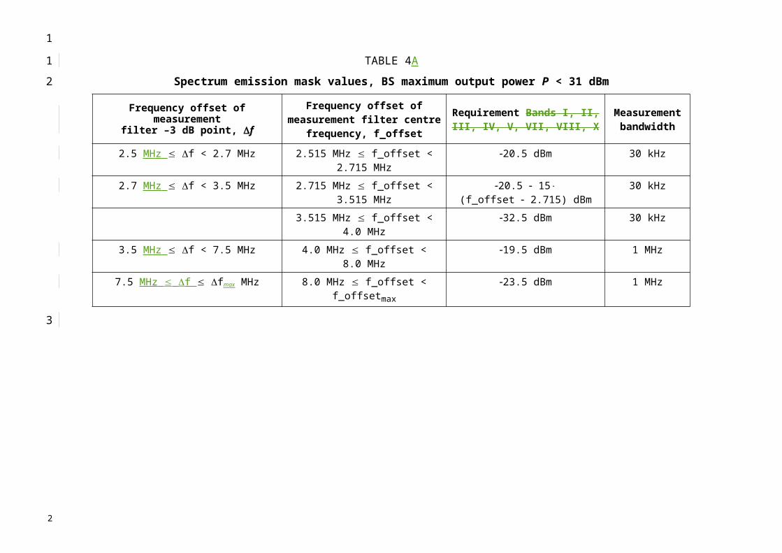
TABLE 4A
Spectrum emission mask values, BS maximum output power P < 31 dBm
Frequency offset of measurementfilter –3 dB point, f
Frequency offset of measurement filter centre frequency, f_offset
Requirement Bands I, II, III, IV, V, VII, VIII, X
Measurement bandwidth
2.5 MHz f < 2.7 MHz 2.515 MHz f_offset < 2.715 MHz 20.5 dBm 30 kHz2.7 MHz f < 3.5 MHz 2.715 MHz f_offset < 3.515 MHz 20.5 15
(f_offset 2.715) dBm30 kHz
3.515 MHz f_offset < 4.0 MHz 32.5 dBm 30 kHz3.5 MHz f < 7.5 MHz 4.0 MHz f_offset < 8.0 MHz 19.5 dBm 1 MHz
7.5 MHz f fmax MHz 8.0 MHz f_offset < f_offsetmax 23.5 dBm 1 MHz
1
1
2
3
4
5
2

- 10 -
For operation in Band II, IV, V, X, XII, XIII and XIV, the applicable additional requirement in Tables 1AA, 2AA or 3AA apply in addition to the minimum requirements in Tables 1A to 4A.Table 1AA
TABLE 1AA
Additional spectrum emission limits for Bands II, IV, XFrequency offset of measurement filter -3dB point,
f
Frequency offset of measurement filter centre frequency,
f_offset
Additional requirement
Measurement bandwidth
2.5 MHz f < 3.5 MHz
2.515MHz f_offset < 3.515MHz
-15 dBm 30 kHz
3.5 MHz f fmax
4.0MHz f_offset < f_offsetmax
-13 dBm 1 MHz
TABLE 2AA
Additional spectrum emission limits for Band VFrequency offset of measurement filter -3dB point,
f
Frequency offset of measurement filter centre frequency,
f_offset
Additional requirement
Measurement bandwidth
2.5 MHz f < 3.5 MHz
2.515MHz f_offset < 3.515MHz
-15 dBm 30 kHz
3.5 MHz f fmax
3.55MHz f_offset < f_offsetmax
-13 dBm 100 kHz
TABLE 3AA
Additional spectrum emission limits for Bands XII, XIII, XIVFrequency offset of measurement filter -3dB point,
f
Frequency offset of measurement filter centre frequency,
f_offset
Additional requirement
Measurement bandwidth
2.5 MHz f < 3.5 MHz
2.515MHz f_offset < 3.515MHz
-13 dBm 30 kHz
3.5 MHz f fmax
3.55MHz f_offset < f_offsetmax
-13 dBm 100 kHz
2.2 E-UTRA (LTE) spectrum mask
The Operating band unwanted emission limits are defined from 10 MHz below the lowest frequency of the BS transmitter operating band up to 10 MHz above the highest frequency of the BS transmitter operating band.
The requirements shall apply whatever the type of transmitter considered (single carrier or multi-carrier) and for all transmission modes foreseen by the manufacturer's specification.
The unwanted emission limits in the part of the operating band that falls in the spurious domain are consistent with Recommendation ITU-R SM.329.
1
123
4
5
6
7
8
9
10
11
121314
1516
1718
3
Emissions should not exceed the maximum level specified in Tables below, where:– f is the separation between the channel edge frequency and the nominal -3dB point of the
measuring filter closest to the carrier frequency.– f_offset is the separation between the channel edge frequency and the centre of the
measuring filter.– f_offsetmax is the offset to the frequency 10 MHz outside the BS transmitter operating band.– fmax is equal to f_offsetmax minus half of the bandwidth of the measuring filter.
For a multicarrier E-UTRA BS the definitions above apply to the lower edge of the carrier transmitted at the lowest carrier frequency and the higher edge of the carrier transmitted at the highest carrier frequency.
The requirements of either § 2.2.1 or § 2.2.2 shall apply.
The Additional operating band unwanted emission limits defined in § 2.2.2.1 may be mandatory in certain regions. In other regions it may not apply.
2.2.1 E-UTRA spectrum mask (Category A)
For E-UTRA BS operating in Bands 5, 6, 8, 12, 13 and 14, emissions shall not exceed the maximum levels specified in Table 1b-a) to 1b-c).
TABLE 1B
1b-a) General operating band unwanted emission limits for 1.4 MHz channel bandwidth (E-UTRA bands <1 GHz) for Category A
Frequency offset of measurement filter
-3dB point, f
Frequency offset of measurement filter centre
frequency, f_offset
Minimum requirement Measurement bandwidth
(Note 1)
0 MHz f < 1.4 MHz 0.05 MHz f_offset < 1.45 MHz100 kHz
1.4 MHz f < 2.8 MHz
1.45 MHz f_offset < 2.85 MHz -9.5 dBm 100 kHz
2.8 MHz f fmax 2.85 MHz f_offset < f_offsetmax -13 dBm 100 kHz
1b-b) General operating band unwanted emission limits for 3 MHz channel bandwidth (E-UTRA bands <1 GHz) for Category A
Frequency offset of measurement filter
-3dB point, f
Frequency offset of measurement filter centre
frequency, f_offset
Minimum requirement Measurement bandwidth
(Note 1)
0 MHz f < 3 MHz 0.05 MHz f_offset < 3.05 MHz100 kHz
3 MHz f fmax 3.05 MHz f_offset < f_offsetmax -13 dBm 100 kHz
1b-c) General operating band unwanted emission limits for 5, 10, 15 and 20 MHz channel bandwidth (E-UTRA bands <1 GHz) for Category A
Frequency offset of measurement filter
-3dB point, f
Frequency offset of measurement filter centre
frequency, f_offset
Minimum requirement Measurement bandwidth
(Note 1)0 MHz f < 5 MHz 0.05 MHz f_offset < 5.05 MHz 100 kHz
5 MHz f < 10 MHz 5.05 MHz f_offset < 10.05 MHz -12.5 dBm 100 kHz 10 MHz f fmax 10.05 MHz f_offset < f_offsetmax -13 dBm 100 kHz
1
1234567
89
10
11
1213
14
1516
17
1819
2021
2223
2
For E-UTRA BS operating in Bands 1, 2, 3, 4, 7, 9, 10, and 11, emissions shall not exceed the maximum levels specified in Table 1b-d) to 1b-f):
1b-d) General operating band unwanted emission limits for 1.4 MHz channel bandwidth (E-UTRA bands >1 GHz) for Category A
Frequency offset of measurement filter
-3dB point, f
Frequency offset of measurement filter centre
frequency, f_offset
Minimum requirement Measurement bandwidth
(Note 1)
0 MHz f < 1.4 MHz 0.05 MHz f_offset < 1.45 MHz100 kHz
1.4 MHz f < 2.8 MHz
1.45 MHz f_offset < 2.85 MHz -9.5 dBm 100 kHz
2.8 MHz f fmax 3.3 MHz f_offset < f_offsetmax -13 dBm 1MHz
1b-e) General operating band unwanted emission limits for 3 MHz channel bandwidth (E-UTRA bands >1 GHz) for Category A
Frequency offset of measurement filter
-3dB point, f
Frequency offset of measurement filter centre
frequency, f_offset
Minimum requirement Measurement bandwidth
(Note 1)
0 MHz f < 3 MHz 0.05 MHz f_offset < 3.05 MHz100 kHz
3 MHz f < 6 MHz 3.05 MHz f_offset < 6.05 MHz -13.5 dBm 100 kHz 6 MHz f fmax 6.5 MHz f_offset < f_offsetmax -13 dBm 1MHz
1b-f) General operating band unwanted emission limits for 5, 10, 15 and 20 MHz channel bandwidth (E-UTRA bands >1 GHz) for Category A
Frequency offset of measurement filter
-3dB point, f
Frequency offset of measurement filter centre
frequency, f_offset
Minimum requirement Measurement bandwidth
(Note 1)0 MHz f < 5 MHz 0.05 MHz f_offset < 5.05 MHz 100 kHz
5 MHz f < 10 MHz 5.05 MHz f_offset < 10.05 MHz -12.5 dBm 100 kHz 10 MHz f fmax 10.5 MHz f_offset < f_offsetmax -13 dBm 1MHz
2.2.2 E-UTRA spectrum mask (Category B)
For E-UTRA BS operating in Bands 5, 6, 8, 12, 13, and 14, emissions shall not exceed the maximum levels specified in Table 2b-a) to 2b-c):
1
1
234
56
7
89
10
1112
13
14
1516
2

TABLE 2B
2b-a) General operating band unwanted emission limits for 1.4 MHz channel bandwidth (E-UTRA bands <1 GHz) for Category B
Frequency offset of measurement filter
-3dB point, f
Frequency offset of measurement filter centre
frequency, f_offset
Minimum requirement Measurement bandwidth
(Note 1)
0 MHz f < 1.4 MHz 0.05 MHz f_offset < 1.45 MHz100 kHz
1.4 MHz f < 2.8 MHz
1.45 MHz f_offset < 2.85 MHz -9.5 dBm 100 kHz
2.8 MHz f fmax 2.85 MHz f_offset < f_offsetmax -16 dBm 100 kHz
2b-b) General operating band unwanted emission limits for 3 MHz channel bandwidth (E-UTRA bands <1 GHz) for Category B
Frequency offset of measurement filter
-3dB point, f
Frequency offset of measurement filter centre
frequency, f_offset
Minimum requirement Measurement bandwidth
(Note 1)
0 MHz f < 3 MHz 0.05 MHz f_offset < 3.05 MHz100 kHz
3 MHz f < 6 MHz 3.05 MHz f_offset < 6.05 MHz -13.5 dBm 100 kHz 6 MHz f fmax 6.05 MHz f_offset < f_offsetmax -16 dBm 100 kHz
2b-c) General operating band unwanted emission limits for 5, 10, 15 and 20 MHz channel bandwidth (E-UTRA bands <1 GHz) for Category B
Frequency offset of measurement filter
-3dB point, f
Frequency offset of measurement filter centre
frequency, f_offset
Minimum requirement Measurement bandwidth
(Note 1)0 MHz f < 5 MHz 0.05 MHz f_offset < 5.05 MHz 100 kHz
5 MHz f < 10 MHz 5.05 MHz f_offset < 10.05 MHz -12.5 dBm 100 kHz 10 MHz f fmax 10.05 MHz f_offset < f_offsetmax -16 dBm 100 kHz
For E-UTRA BS operating in Bands 1, 2, 3, 4, 7, 9, 10, and 11 emissions shall not exceed the maximum levels specified in Table 2b-d) to 2b-f):
2b-d) General operating band unwanted emission limits for 1.4 MHz channel bandwidth (E-UTRA bands >1 GHz) for Category B
Frequency offset of measurement filter
-3dB point, f
Frequency offset of measurement filter centre
frequency, f_offset
Minimum requirement Measurement bandwidth
(Note 1)
0 MHz f < 1.4 MHz 0.05 MHz f_offset < 1.45 MHz100 kHz
1.4 MHz f < 2.8 MHz
1.45 MHz f_offset < 2.85 MHz -9.5 dBm 100 kHz
2.8 MHz f fmax 3.3 MHz f_offset < f_offsetmax -15 dBm 1MHz
1
1
23
4
56
7
89
10
11121314
2
2b-e) General operating band unwanted emission limits for 3 MHz channel bandwidth (E-UTRA bands >1 GHz) for Category B
Frequency offset of measurement filter
-3dB point, f
Frequency offset of measurement filter centre
frequency, f_offset
Minimum requirement Measurement bandwidth
(Note 1)
0 MHz f < 3 MHz 0.05 MHz f_offset < 3.05 MHz100 kHz
3 MHz f < 6 MHz 3.05 MHz f_offset < 6.05 MHz -13.5 dBm 100 kHz 6 MHz f fmax 6.5 MHz f_offset < f_offsetmax -15 dBm 1MHz
2b-f) General operating band unwanted emission limits for 5, 10, 15 and 20 MHz channel bandwidth (E-UTRA bands >1 GHz) for Category B
Frequency offset of measurement filter
-3dB point, f
Frequency offset of measurement filter centre
frequency, f_offset
Minimum requirement Measurement bandwidth
(Note 1)0 MHz f < 5 MHz 0.05 MHz f_offset < 5.05 MHz 100 kHz
5 MHz f < 10 MHz 5.05 MHz f_offset < 10.05 MHz -12.5 dBm 100 kHz 10 MHz f fmax 10.5 MHz f_offset < f_offsetmax -15 dBm 1MHz
2.2.2.1 E-UTRA spectrum mask (additional limits)
The following requirements may apply in certain regions. For E-UTRA BS operating in Bands 5, emissions shall not exceed the maximum levels specified in Table 3b.
1
1
23
4
56
7
8
910
2

TABLE 3B
Additional operating band unwanted emission limits for E-UTRA bands <1 GHzChannel
bandwidthFrequency offset of measurement filter
-3dB point, f
Frequency offset of measurement filter centre
frequency, f_offset
Minimum requirement
Measurement bandwidth
(Note 1)
1.4 MHz0 MHz f < 1 MHz 0.005 MHz f_offset < 0.995
MHz -12.5 dBm 10 kHz
1 MHz f < 2.8 MHz 1.05 MHz f_offset < 2.85 MHz -11.5 dBm 100 kHz2.8 MHz f < fmax 2.85 MHz f_offset < f_offsetmax -13 dBm
3 MHz0 MHz f < 1 MHz 0.015 MHz f_offset < 0.985
MHz -11.5 dBm 30 kHz
1 MHz f < 6 MHz 1.05 MHz f_offset < 6.05 MHz -11.5 dBm 100 kHz6 MHz f < fmax 6.05 MHz f_offset < f_offsetmax -13 dBm
5 MHz0 MHz f < 1 MHz 0.015 MHz f_offset < 0.985
MHz -13.5 dBm 30 kHz
1 MHz f < 10 MHz 1.05 MHz f_offset < 10.05 MHz -11.5 dBm 100 kHz10 MHz f < fmax 10.05 MHz f_offset < f_offsetmax -13 dBm
10 MHz0 MHz f < 1 MHz 0.05 MHz f_offset < 0.95 MHz -11.5 dBm
100 kHz 1 MHz f < 20 MHz 1.05 MHz f_offset < 20.05 MHz -11.5 dBm20 MHz f < fmax 20.05 MHz f_offset < f_offsetmax -13 dBm
15 MHz0 MHz f < 1 MHz 0.05 MHz f_offset < 0.95 MHz -11.5 dBm
100 kHz 1 MHz f < 30 MHz 1.05 MHz f_offset < 30.05 MHz -11.5 dBm30 MHz f < fmax 30.05 MHz f_offset < f_offsetmax -13 dBm
20 MHz0 MHz f < 1 MHz 0.05 MHz f_offset < 0.95 MHz -11.5 dBm
100 kHz 1 MHz f < 40 MHz 1.05 MHz f_offset < 40.05 MHz -11.5 dBm40 MHz f < fmax 40.05 MHz f_offset < f_offsetmax -13 dBm
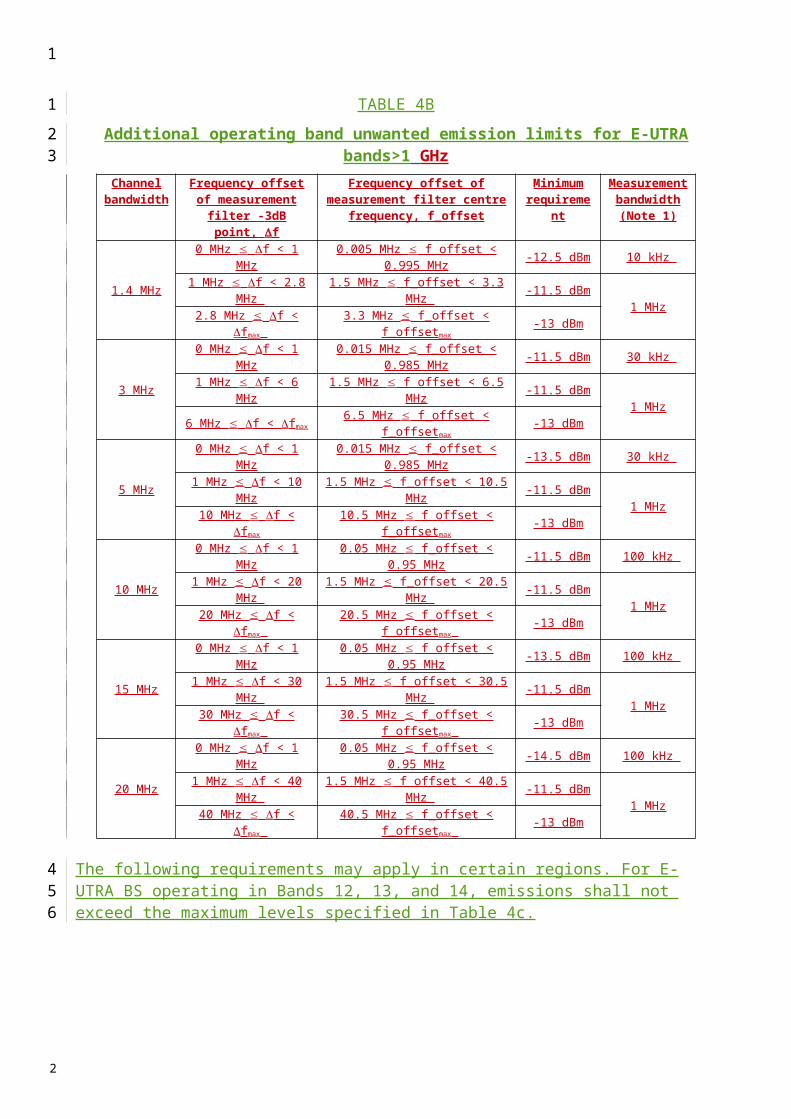
The following requirements may apply in certain regions. For E-UTRA BS operating in Bands 2, 4 and 10, emissions shall not exceed the maximum levels specified in Table 4b.
TABLE 4B
Additional operating band unwanted emission limits for E-UTRA bands>1 GHzChannel
bandwidthFrequency offset of measurement filter
-3dB point, f
Frequency offset of measurement filter centre
frequency, f_offset
Minimum requirement
Measurement bandwidth
(Note 1)
1.4 MHz0 MHz f < 1 MHz 0.005 MHz f_offset < 0.995
MHz -12.5 dBm 10 kHz
1 MHz f < 2.8 MHz 1.5 MHz f_offset < 3.3 MHz -11.5 dBm 1 MHz2.8 MHz f < fmax 3.3 MHz f_offset < f_offsetmax -13 dBm
3 MHz0 MHz f < 1 MHz 0.015 MHz f_offset < 0.985
MHz -11.5 dBm 30 kHz
1 MHz f < 6 MHz 1.5 MHz f_offset < 6.5 MHz -11.5 dBm 1 MHz6 MHz f < fmax 6.5 MHz f_offset < f_offsetmax -13 dBm
5 MHz0 MHz f < 1 MHz 0.015 MHz f_offset < 0.985
MHz -13.5 dBm 30 kHz
1 MHz f < 10 MHz 1.5 MHz f_offset < 10.5 MHz -11.5 dBm 1 MHz10 MHz f < fmax 10.5 MHz f_offset < f_offsetmax -13 dBm
10 MHz0 MHz f < 1 MHz 0.05 MHz f_offset < 0.95 MHz -11.5 dBm 100 kHz
1 MHz f < 20 MHz 1.5 MHz f_offset < 20.5 MHz -11.5 dBm 1 MHz20 MHz f < fmax 20.5 MHz f_offset < f_offsetmax -13 dBm
15 MHz0 MHz f < 1 MHz 0.05 MHz f_offset < 0.95 MHz -13.5 dBm 100 kHz
1 MHz f < 30 MHz 1.5 MHz f_offset < 30.5 MHz -11.5 dBm 1 MHz30 MHz f < fmax 30.5 MHz f_offset < f_offsetmax -13 dBm
20 MHz0 MHz f < 1 MHz 0.05 MHz f_offset < 0.95 MHz -14.5 dBm 100 kHz
1 MHz f < 40 MHz 1.5 MHz f_offset < 40.5 MHz -11.5 dBm 1 MHz40 MHz f < fmax 40.5 MHz f_offset < f_offsetmax -13 dBm
1
1
2
34
5
6
2

The following requirements may apply in certain regions. For E-UTRA BS operating in Bands 12, 13, and 14, emissions shall not exceed the maximum levels specified in Table 4c.
1
12
2

TABLE 4C
Additional operating band unwanted emission limits for E-UTRA (bands 12, 13 and 14)Channel
bandwidthFrequency offset of measurement filter
-3dB point, f
Frequency offset of measurement filter centre
frequency, f_offset
Minimum requirement
Measurement bandwidth
(Note 1)1.4 MHz3 MHz5 MHz
10 MHz15 MHz20 MHz
0 MHz f < 100 kHz 0.015 MHz f_offset < 0.085 MHz -11.5 dBm 30 kHz
1.4 MHz100 kHz f < 2.8
MHz 150 kHz f_offset < 2.85 MHz -11.5 dBm 100 kHz2.8 MHz f < fmax 2.85 MHz f_offset < f_offsetmax -13 dBm
3 MHz 100 kHz f < 6 MHz 150 kHz f_offset < 6.05 MHz -11.5 dBm 100 kHz6 MHz f < fmax 6.05 MHz f_offset < f_offsetmax -13 dBm
5 MHz 100 kHz f < 10 MHz 150 kHz f_offset < 10.05 MHz -11.5 dBm 100 kHz10 MHz f < fmax 10.05 MHz f_offset < f_offsetmax -13 dBm
10 MHz 100 kHz f < 20 MHz 150 kHz f_offset < 20.05 MHz -11.5 dBm 100 kHz20 MHz f < fmax 20.05 MHz f_offset < f_offsetmax -13 dBm
15 MHz 100 kHz f < 30 MHz 150 kHz f_offset < 30.05 MHz -11.5 dBm 100 kHz30 MHz f < fmax 30.05 MHz f_offset < f_offsetmax -13 dBm
20 MHz 100 kHz f < 40 MHz 150 kHz f_offset < 40.05 MHz -11.5 dBm 100 kHz40 MHz f < fmax 40.05 MHz f_offset < f_offsetmax -13 dBm
NOTE 1 – As a general rule for the requirements in section 2.2, the resolution bandwidth of the measuring equipment should be equal to the measurement bandwidth. However, to improve measurement accuracy, sensitivity and efficiency, the resolution bandwidth can be smaller than the measurement bandwidth. When the resolution bandwidth is smaller than the measurement bandwidth, the result should be integrated over the measurement bandwidth in order to obtain the equivalent noise bandwidth of the measurement bandwidth.
3 Adjacent channel leakage power ratio
Adjacent channel leakage power ratio (ACLR) is the ratio of the transmitted power to the power measured after a receiver filter in the adjacent channel(s).
3.1 ACLR for UTRA
For UTRA, Bboth the transmitted power and the received power are measured through a matched filter (root raised cosine and roll-off 0.22) with a noise power bandwidth equal to the chip rate. The requirements should apply whatever the type of transmitter considered (single carrier or multi-carrier). It applies for all transmission modes foreseen by the manufacturer’s specification.
The limit for ACLR should be as specified in Table 5a.
1
1
2
345678
9
1011
12
13141516
17
2
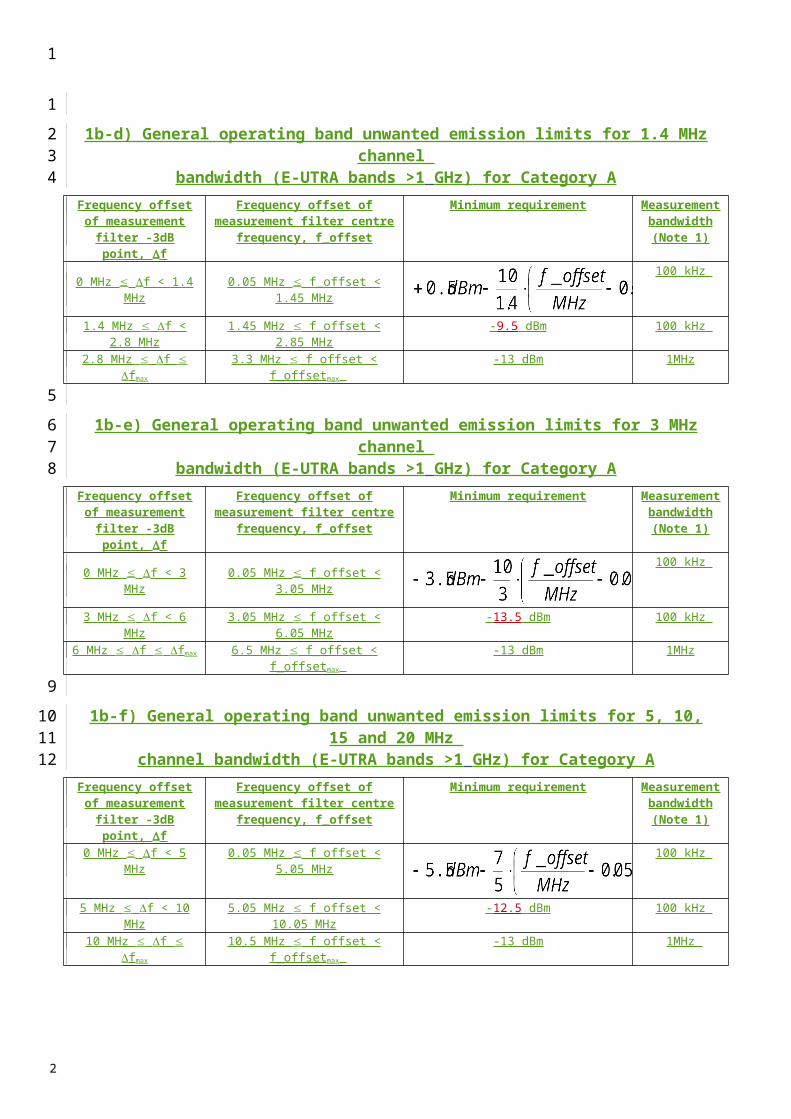
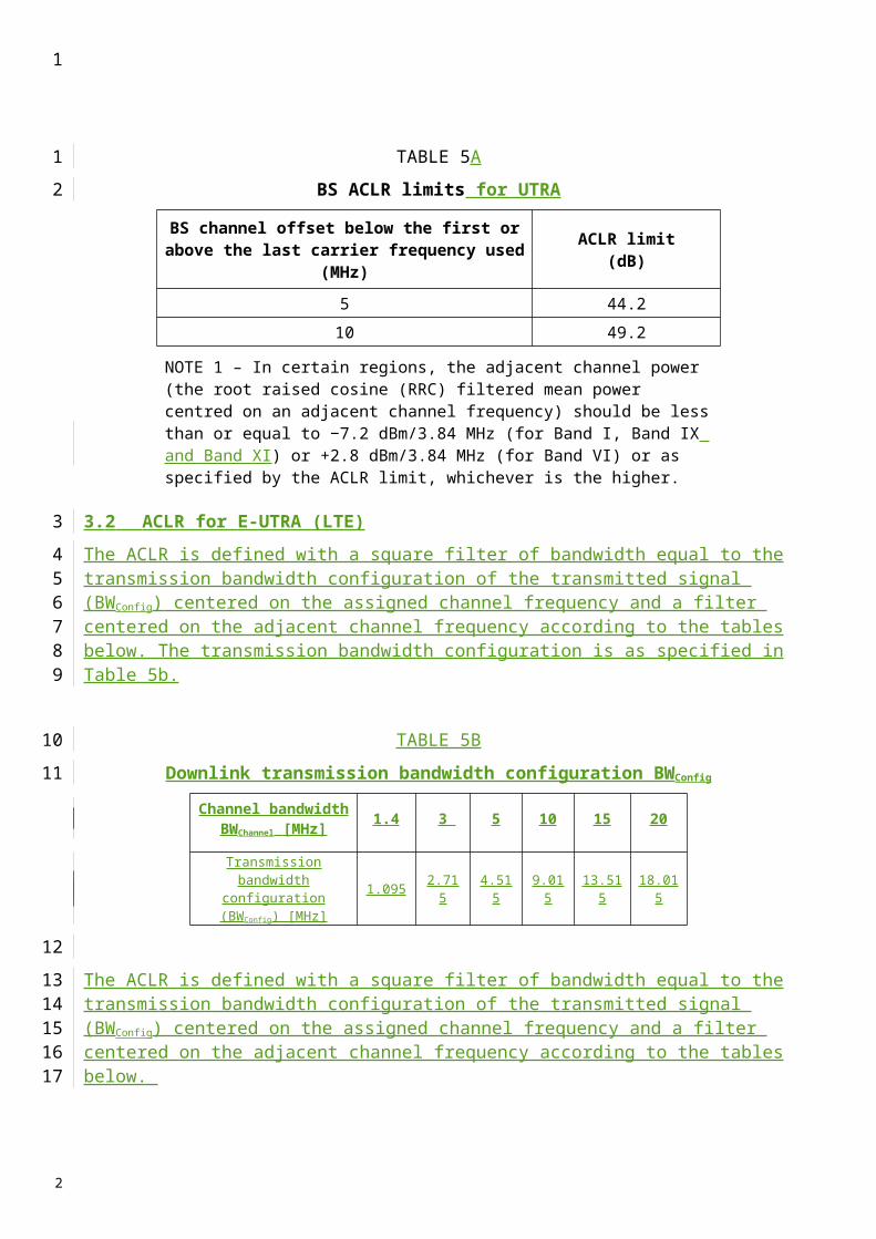
TABLE 5A
BS ACLR limits for UTRA
BS channel offset below the first or above the last carrier frequency used
(MHz)
ACLR limit(dB)
5 44.210 49.2
NOTE 1 – In certain regions, the adjacent channel power (the root raised cosine (RRC) filtered mean power centred on an adjacent channel frequency) should be less than or equal to −7.2 dBm/3.84 MHz (for Band I, Band IX and Band XI) or +2.8 dBm/3.84 MHz (for Band VI) or as specified by the ACLR limit, whichever is the higher.
3.2 ACLR for E-UTRA (LTE)
The ACLR is defined with a square filter of bandwidth equal to the transmission bandwidth configuration of the transmitted signal (BWConfig) centered on the assigned channel frequency and a filter centered on the adjacent channel frequency according to the tables below. The transmission bandwidth configuration is as specified in Table 5b.
TABLE 5B
Downlink transmission bandwidth configuration BWConfig
Channel bandwidth BWChannel [MHz] 1.4 3 5 10 15 20
Transmission bandwidth configuration (BWConfig)
[MHz]1.095 2.715 4.515 9.015 13.515 18.015
The ACLR is defined with a square filter of bandwidth equal to the transmission bandwidth configuration of the transmitted signal (BWConfig) centered on the assigned channel frequency and a filter centered on the adjacent channel frequency according to the tables below.
For Category A, either the ACLR limits in the tables below or the absolute limit of -13 dBm/MHz apply, whichever is less stringent.
For Category B, either the ACLR limits in the tables below or the absolute limit of -15 dBm/MHz apply, whichever is less stringent.
For operation in paired spectrum, the ACLR shall be higher than the value specified in Table 5c.
1
1
2
3
4567
8
9
10
111213
1415
1617
18
2

TABLE 5C
BS ACLR limits for E-UTRA (LTE) in paired spectrum E-UTRA transmitted
signal channel bandwidth BWChannel
[MHz]
BS adjacent channel centre frequency
offset below the first or above the last
carrier centre frequency used
Assumed adjacent channel carrier
(informative)
Filter on the adjacent channel frequency and
corresponding filter bandwidth
ACLR limit
1.4, 3.0, 5, 10, 15, 20 BWChannel E-UTRA of same BW Square (BWConfig) 44.2 dB2 x BWChannel E-UTRA of same BW Square (BWConfig) 44.2 dB
BWChannel /2 + 2.5 MHz 3.84 Mcps UTRA RRC (3.84 Mcps) 44.2 dBBWChannel /2 + 7.5 MHz 3.84 Mcps UTRA RRC (3.84 Mcps) 44.2 dB
NOTE 1: BWChannel and BWConfig are the channel bandwidth and transmission bandwidth configuration of the E-UTRA transmitted signal on the assigned channel frequency..
4 Transmitter spurious emission (conducted)
The spurious emission is measured at the BS RF output port.
For UTRA, Tthe requirement applies at frequencies within the specified frequency ranges, which are more than 12.5 MHz under the first carrier frequency used or more than 12.5 MHz above the last carrier frequency used.
For E-UTRA (LTE), the requirement applies at frequencies within the specified frequency ranges, excluding the frequency range from 10 MHz below the lowest frequency of the BS transmitter operating band up to 10 MHz above the highest frequency of the BS transmitter operating band.
The requirement below should apply whatever the type of transmitter considered (single carrier or multi-carrier). It applies for all transmission modes foreseen by the manufacturer’s specification.
Unless otherwise stated, all requirements are measured as mean power (r.m.s.).
4.1 Mandatory requirements
The requirements of either§ 4.1.1 or§ 4.1.2 applies.
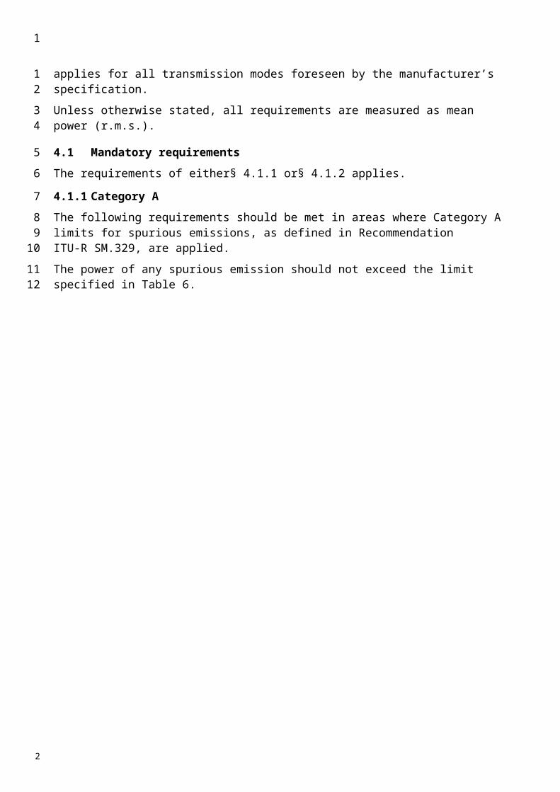
4.1.1 Category A
The following requirements should be met in areas where Category A limits for spurious emissions, as defined in Recommendation ITU-R SM.329, are applied.
The power of any spurious emission should not exceed the limit specified in Table 6.
1
1
2
3
4
567
89
10
1112
13
14
15
16
1718
19
2
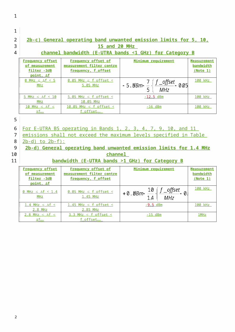
TABLE 6
BS spurious emission limit, Category A
Band Maximum level
Measurement bandwidth Note
9 kHz-150 kHz 13 dBm 1 kHz Bandwidth as inRecommendation ITU-R SM.329, § 4.1
150 kHz-30 MHz 10 kHz Bandwidth as in Recommendation ITU-R SM.329, § 4.1
30 MHz-1 GHz 100 kHz Bandwidth as inRecommendation ITU-R SM.329, § 4.1
1 GHz-12.75 GHz 1 MHz Upper frequency as inRecommendation ITU-R SM.329, § 2.5 Table 1
4.1.2 Category B
4.1.2.1 Category B for UTRA
The following requirements should be met in areas where Category B limits for spurious emissions, as defined in Recommendation ITU-R SM.329, are applied.
The power of any spurious emission should not exceed the limit specified in Tables 7a) and 7b).
TABLE 7
a) BS mandatory spurious emission limits, operating Band I, II, III, IV, VII, X (Category B)
Band Maximum level Measurement bandwidth Note
9 « 150 kHz 36 dBm 1 kHz (1)
150 kHz « 30 MHz 36 dBm 10 kHz (1)
30 MHz « 1 GHz 36 dBm 100 kHz (1)
1 GHz « Flow – 10 MHz 30 dBm 1 MHz (1)
Flow – 10 MHz « Fhigh + 10 MHz 15 dBm 1 MHz (2)
Fhigh + 10 MHz « 12.75 GHz 30 dBm 1 MHz (3)
b) BS mandatory spurious emission limits, operating Band V, VIII, XII, XIII, XIV (Category B)
Band Maximum level Measurement bandwidth Note
9 « 150 kHz 36 dBm 1 kHz (1)
150 kHz « 30 MHz 36 dBm 10 kHz (1)
30 MHz « Flow – 10 MHz 36 dBm 100 kHz (1)
Flow – 10 MHz « Fhigh + 10 MHz 16 dBm 100 kHz (2)
Fhigh + 10 MHz « 1 GHz 36 dBm 100 kHz (1)
1 GHz « 12.75 GHz 30 dBm 1 MHz (3)
(1) Bandwidth as in Recommendation ITU-R SM.329, § 4.1.(2) Limit based on Recommendation ITU-R SM.329, § 4.3 and Annex 7.(3) Bandwidth as in Recommendation ITU-R SM.329, § 4.1. Upper frequency as in Recommendation ITU-R SM.329,
§ 2.5 Table 1.Flow: the lowest downlink frequency of the operating band.Fhigh: the highest downlink frequency of the operating band.
1
1
2
3
4
56
7
8
9
10
2

4.1.2.2 Category B for E-UTRA
The following requirements should be met in areas where Category B limits for spurious emissions, as defined in Recommendation ITU-R SM.329, are applied.
The power of any spurious emission should not exceed the limit specified in Tables 7c.
TABLE 7CBand Maximum
LevelMeasurement
BandwidthNote
9 kHz « 150 kHz -36 dBm 1 kHz Note 1 150 kHz « 30 MHz -36 dBm 10 kHz Note 130 MHz « 1 GHz -36 dBm 100 kHz Note 1
1 GHz « 12.75 GHz -30 dBm 1 MHz Note 2NOTE 1 - Bandwidth as in ITU-R SM.329, §4.1NOTE 2 - Bandwidth as in ITU-R SM.329, §4.1. Upper frequency as in ITU-R SM.329, §2.5 Table 1
4.2 Coexistence with other systems in the same geographical area
4.2.1 Coexistence with other systems in the same geographical area for UTRA
These requirements may be applied for the protection of UE, MS and/or BS operating in other frequency bands in the same geographical area. The requirements may apply in geographic areas in which both UTRA FDD operating in frequency Bands I to XIV and a system operating in another frequency band than the FDD operating band are deployed. The system operating in the other frequency band may be GSM900, DCS1800, PCS1900, GSM850 and/or FDD operating in Bands I to XIV.
The power of any spurious emission should not exceed the limits of Table 8(a) for a BS where requirements for coexistence with the system listed in the first column apply.
TABLE 8(A)
BS spurious emission limits for UTRA BS in geographic coverage area of systems operating in other frequency bands
System type operating in
the same geographical
area
Band for coexistence
requirement
Maximum level
Measurement bandwidth Note
GSM900
921-960 MHz −57 dBm 100 kHz This requirement does not apply to UTRA FDD operating in Band VIII
876-915 MHz −61 dBm 100 kHzFor the frequency range 880-915 MHz, this requirement does not apply to UTRA FDD operating in Band VIII
DCS18001 805-1 880 MHz −47 dBm 100 kHz This requirement does not apply to
UTRA FDD operating in Band III
1 710-1 785 MHz −61 dBm 100 kHz This requirement does not apply to UTRA FDD operating in Band III
PCS1900 1 930-1 990 MHz −47 dBm 100 kHz This requirement does not apply to UTRA FDD BS operating in frequency band II
1
1
23
4
5
6
7
89
10111213
1415
16
1718
2

1 850-1 910 MHz −61 dBm 100 kHzThis requirement does not apply to UTRA FDD BS operating in frequency band II
GSM850 or CDMA850
869-894 MHz −57 dBm 100 kHzThis requirement does not apply to UTRA FDD BS operating in frequency band V
824-849 MHz −61 dBm 100 kHzThis requirement does not apply to UTRA FDD BS operating in frequency band V
FDD Band I2 110-2 170 MHz −52 dBm 1 MHz This requirement does not apply to
UTRA FDD BS operating in Band I
1 920-1 980 MHz −49 dBm 1 MHz This requirement does not apply to UTRA FDD BS operating in band I
FDD Band II1 930-1 990 MHz −52 dBm 1 MHz This requirement does not apply to
UTRA FDD BS operating in Band II
1 850-1 910 MHz −49 dBm 1 MHz This requirement does not apply to UTRA FDD BS operating in band II
TABLE 8(A) (End)
System type operating in
the same geographical
area
Band for coexistence
requirement
Maximum level
Measurement bandwidth Note
FDD Band III1 805-1 880 MHz −52 dBm 1 MHz This requirement does not apply to
UTRA FDD BS operating in Band III
1 710-1 785 MHz −49 dBm 1 MHz This requirement does not apply to UTRA FDD BS operating in Band III
FDD Band IV2 110-2 155 MHz −52 dBm 1 MHz This requirement does not apply to
UTRA FDD BS operating in Band IV
1 710-1 755 MHz −49 dBm 1 MHz This requirement does not apply to UTRA FDD BS operating in Band IV
FDD Band V869-894 MHz −52 dBm 1 MHz This requirement does not apply to
UTRA FDD BS operating in Band V
824-849 MHz −49 dBm 1 MHz This requirement does not apply to UTRA FDD BS operating in Band V
FDD Band VI860-895 MHz −52 dBm 1 MHz This requirement does not apply to
UTRA FDD BS operating in Band VI
815-850 MHz −49 dBm 1 MHz This requirement does not apply to UTRA FDD BS operating in Band VI
FDD Band VII2 620-2 690 MHz −52 dBm 1 MHz This requirement does not apply to
UTRA FDD BS operating in Band VII
2 500-2 570 MHz −49 dBm 1 MHz This requirement does not apply to UTRA FDD BS operating in Band VII
FDD Band VIII925-960 MHz −52 dBm 1 MHz This requirement does not apply to
UTRA FDD BS operating in Band VIII
880-915 MHz −49 dBm 1 MHz This requirement does not apply to UTRA FDD BS operating in Band VIII
FDD Band IX1 844.9-1 879.9 MHz −52 dBm 1 MHz This requirement does not apply to
UTRA FDD BS operating in Band IX
1 749.9-1 784.9 MHz −49 dBm 1 MHz This requirement does not apply to UTRA FDD BS operating in Band IX
1
1
2
FDD Band X2 110-2 170 MHz −52 dBm 1 MHz This requirement does not apply to
UTRA FDD BS operating in Band X
1 710-1 770 MHz −49 dBm 1 MHz This requirement does not apply to UTRA FDD BS operating in Band X
FDD Band XI1 475.9-1 500.9 MHz −52 dBm 1 MHz This requirement does not apply to
UTRA FDD BS operating in Band XI
1 427.9-1 452.9 MHz −49 dBm 1 MHz This requirement does not apply to UTRA FDD BS operating in Band XI
FDD Band XII728-746 MHz -52 dBm 1 MHz This requirement does not apply to
UTRA FDD BS operating in band XII
698-716 MHz -49 dBm 1 MHz This requirement does not apply to UTRA FDD BS operating in band XII
FDD Band XIII746-756 MHz -52 dBm 1 MHz This requirement does not apply to
UTRA FDD BS operating in band XIII
777-787 MHz -49 dBm 1 MHz This requirement does not apply to UTRA FDD BS operating in band XIII
FDD Band XIV
758-768 MHz -52 dBm 1 MHz This requirement does not apply to UTRA FDD BS operating in band XIV
788-798 MHz -49 dBm 1 MHz This requirement does not apply to UTRA FDD BS operating in band XIV
4.2.2 Coexistence with other systems in the same geographical area for E-UTRA
These requirements may be applied for the protection of UE, MS and/or BS operating in other frequency bands in the same geographical area. The requirements may apply in geographic areas in which both E-UTRA BS and a system operating in another frequency band than the E-UTRA operating band are deployed. The system operating in the other frequency band may be GSM900, DCS1800, PCS1900, GSM850, UTRA FDD/TDD and/or E-UTRA.
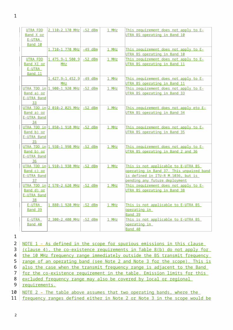
The power of any spurious emission shall not exceed the limits of Table 8(b) for a BS where requirements for co-existence with the system listed in the first column apply.
TABLE 8(B)
BS spurious emission limits for E-UTRA BS in geographic coverage area of systems operating in other frequency bands
System type operating in
the same geographical
area
Band for co-existence
requirement
Maximum Level
Measurement Bandwidth
Note
GSM900 921 - 960 MHz -57 dBm 100 kHz This requirement does not apply to E-UTRA BS operating in Band 8
876 - 915 MHz -61 dBm 100 kHz For the frequency range 880-915 MHz, this requirement does not apply to E-UTRA BS operating in Band 8
DCS1800 1805 - 1880 MHz -47 dBm 100 kHz This requirement does not apply to E-UTRA BS operating in Band 3
1710 - 1785 MHz -61 dBm 100 kHz This requirement does not apply to E-UTRA BS operating in Band 3
PCS1900 1930 - 1990 MHz -47 dBm 100 kHz This requirement does not apply to E-UTRA BS operating in frequency Band 2 or Band 36
1850 - 1910 MHz -61 dBm 100 kHz This requirement does not apply to E-UTRA BS operating in frequency Band 2. This requirement does not apply to E-UTRA BS operating in frequency Band 35
1
1
23456
78
9
1011
2

GSM850 869 - 894 MHz -57 dBm 100 kHz This requirement does not apply to E-UTRA BS operating in frequency Band 5
824 - 849 MHz -61 dBm 100 kHz This requirement does not apply to E-UTRA BS operating in frequency Band 5
UTRA FDD Band I orE-UTRA Band 1
2110 - 2170 MHz -52 dBm 1 MHz This requirement does not apply to E-UTRA BS operating in Band 1
1920 - 1980 MHz -49 dBm 1 MHz This requirement does not apply to E-UTRA BS operating in Band 1
UTRA FDD Band II orE-UTRA Band 2
1930 - 1990 MHz -52 dBm 1 MHz This requirement does not apply to E-UTRA BS operating in Band 2
1850 - 1910 MHz -49 dBm 1 MHz This requirement does not apply to E-UTRA BS operating in Band 2
UTRA FDD Band III orE-UTRA Band 3
1805 - 1880 MHz -52 dBm 1 MHz This requirement does not apply to E-UTRA BS operating in Band 3
1710 - 1785 MHz -49 dBm 1 MHz This requirement does not apply to E-UTRA BS operating in Band 3
UTRA FDD Band IV orE-UTRA Band 4
2110 - 2155 MHz -52 dBm 1 MHz This requirement does not apply to E-UTRA BS operating in Band 4
1710 - 1755 MHz -49 dBm 1 MHz This requirement does not apply to E-UTRA BS operating in Band 4
UTRA FDD Band V orE-UTRA Band 5
869 - 894 MHz -52 dBm 1 MHz This requirement does not apply to E-UTRA BS operating in Band 5
824 - 849 MHz -49 dBm 1 MHz This requirement does not apply to E-UTRA BS operating in Band 5
TABLE 8(B) (End) System type operating in
the same geographical
area
Band for co-existence
requirement
Maximum Level
Measurement Bandwidth
Note
UTRA FDD Band VI orE-UTRA Band 6
860-895 MHz -52 dBm 1 MHz This requirement does not apply to E-UTRA BS operating in Band 6
815-850 MHz -49 dBm 1 MHz This requirement does not apply to E-UTRA BS operating in Band 6
UTRA FDD Band VII orE-UTRA Band 7
2 620-2 690 MHz -52 dBm 1 MHz This requirement does not apply to E-UTRA BS operating in Band 7
2 500-2 570 MHz -49 dBm 1 MHz This requirement does not apply to E-UTRA BS operating in Band 7
UTRA FDD Band VIII or
E-UTRA Band 8
925-960 MHz -52 dBm 1 MHz This requirement does not apply to E-UTRA BS operating in Band 8
880-915 MHz -49 dBm 1 MHz This requirement does not apply to E-UTRA BS operating in Band 8
UTRA FDD Band IX orE-UTRA Band 9
1 844.9-1 879.9 MHz
-52 dBm 1 MHz This requirement does not apply to E-UTRA BS operating in Band 9
1 749.9-1 784.9 MHz
-49 dBm 1 MHz This requirement does not apply to E-UTRA BS operating in Band 9
UTRA FDD Band X orE-UTRA Band 10
2 110-2 170 MHz -52 dBm 1 MHz This requirement does not apply to E-UTRA BS operating in Band 10
1 710-1 770 MHz -49 dBm 1 MHz This requirement does not apply to E-UTRA BS operating in Band 10
1
1
2

UTRA FDD Band XI orE-UTRA Band 11
1 475.9-1 500.9 MHz
-52 dBm 1 MHz This requirement does not apply to E-UTRA BS operating in Band 11
1 427.9-1 452.9 MHz
-49 dBm 1 MHz This requirement does not apply to E-UTRA BS operating in Band 11
UTRA TDD in Band a) or E-
UTRA Band 33
1 900-1 920 MHz -52 dBm 1 MHz This requirement does not apply to E-UTRA BS operating in Band 33
UTRA TDD in Band a) or E-
UTRA Band 34
2 010-2 025 MHz -52 dBm 1 MHz This requirement does not apply eto E-UTRA BS operating in Band 34
UTRA TDD in Band b) or E-
UTRA Band 35
1 850-1 910 MHz -52 dBm 1 MHz This requirement does not apply to E-UTRA BS operating in Band 35
UTRA TDD in Band b) or E-
UTRA Band 36
1 930-1 990 MHz -52 dBm 1 MHz This requirement does not apply to E-UTRA BS operating in Band 2 and 36
UTRA TDD in Band c) or E-
UTRA Band 37
1 910-1 930 MHz -52 dBm 1 MHz This is not applicable to E-UTRA BS operating in Band 37. This unpaired band is defined in ITU-R M.1036, but is pending any future deployment
UTRA TDD in Band d) or E-
UTRA Band 38
2 570-2 620 MHz -52 dBm 1 MHz This requirement does not apply to E-UTRA BS operating in Band 38
E-UTRA Band 39
1 880-1 920 MHz -52 dBm 1 MHz This is not applicable to E-UTRA BS operating in Band 39
E-UTRA Band 40
2 300-2 400 MHz -52 dBm 1 MHz This is not applicable to E-UTRA BS operating in Band 40
NOTE 1 – As defined in the scope for spurious emissions in this clause (clause 4), the co-existence requirements in Table 8(b) do not apply for the 10 MHz frequency range immediately outside the BS transmit frequency range of an operating band (see Note 2 and Note 3 for the scope). This is also the case when the transmit frequency range is adjacent to the Band for the co-existence requirement in the table. Emission limits for this excluded frequency range may also be covered by local or regional requirements.NOTE 2 – The table above assumes that two operating bands, where the frequency ranges defined either in Note 2 or Note 3 in the scope would be overlapping, are not deployed in the same geographical area. For such a case of operation with overlapping frequency arrangements in the same geographical area, special co-existence requirements may apply that are not covered by this recommendation.
4.3 Coexistence with PHS
This requirement may be applied for the protection of PHS in geographic areas in which both PHS and UTRA FDD or E-UTRA FDD are deployed. For UTRA FDD, tThis requirement is also applicable at specified frequencies falling between 12.5 MHz below the first carrier frequency used and 12.5 MHz above the last carrier frequency used. For E-UTRA FDD, this requirement is also applicable at specified frequencies falling between 10 MHz below the lowest BS transmitter frequency of the operating band and 10 MHz above the highest BS transmitter frequency of the operating band.
1
123456789
10
11
12131415161718
2
The power of any spurious emission should not exceed:
TABLE 9
BS spurious emission limits for BS in geographic coverage area of PHSBand Measurement bandwidth Maximum level Note
1 884.5 to 1 919.6 MHz 300 kHz 41 dBm
4.4 Coexistence with UTRA-TDD
This requirement may be applied to geographic areas in which both UTRA-TDD and UTRA-FDD are deployed.
The power of any spurious emission should not exceed:
TABLE 10
BS spurious emission limits for UTRA BS in geographic coverage area of UTRA-TDDBand Measurement bandwidth Maximum level Note
1 900 to 1 920 MHz 1 MHz 52 dBm2 010 to 2 025 MHz 1 MHz 52 dBm2 570 to 2 610 MHz 1 MHz 52 dBm
5 Receiver spurious emission
The requirements apply to all BS with separate receiver and transmitter antenna port. The test should be performed when both transmitter and receiver are on with the transmitter port terminated.
For all BS with common receiver and transmitter antenna ports the transmitter spurious emission as specified above is valid.
The power of any spurious emission should not exceed the limit specified in Tables 11a) and 11b).
For E-UTRA, in addition to the requirements in Table 11, the power of any spurious emission should not exceed the levels specified for Co-existence with other systems in the same geographical area in Clause 4.2.2 and Clause 4.3.
TABLE 11
a) Receiver spurious emission limits
Band Maximum level
Measurement bandwidth Note
30 MHz-1 GHz 57 dBm 100 kHz1-12.75 GHz 47 dBm 1 MHz With the exception of frequencies between
12.5 MHz below the first carrier frequency and 12.5 MHz above the last carrier frequency used by the BS transmitter
NOTE 1 – For UTRA, frequencies between 12.5 MHz below the first carrier frequency and 12.5 MHz above the last carrier frequency used by the BS transmitter are excluded.NOTE 2 – For E-UTRA, the frequency range between 2.5 * BWChannel below the first carrier frequency and 2.5 * BWChannel above the last carrier frequency transmitted by the BS, where BWChannel is the channel bandwidth, may be excluded from the requirement. However, frequencies that are more than 10 MHz below the lowest frequency of the BS transmitter operating band or more than 10 MHz above the highest frequency of the BS transmitter operating band shall not be excluded from the requirement.
1
1
2
3
4
56
7
8
9
10
1112
1314
15
161718
19
20
2
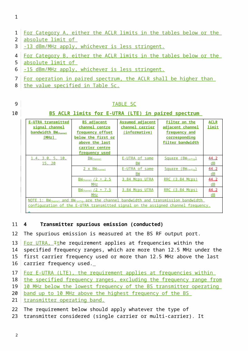
TABLE 11 (End)
b) Additional spurious emission requirements for UTRAOperating
Band Band Maximum level Measurement bandwidth Note
I 1 920-1 980 MHz −78 dBm 3.84 MHzII 1 850-1 910 MHz −78 dBm 3.84 MHzIII 1 710-1 785 MHz −78 dBm 3.84 MHzIV 1 710-1 755 MHz −78 dBm 3.84 MHzV 824-849 MHz −78 dBm 3.84 MHzVI 815-850 MHz −78 dBm 3.84 MHzVII 2 500-2 570 MHz −78 dBm 3.84 MHzVIII 880-915 MHz −78 dBm 3.84 MHzIX 1 749.9-1 784.9 MHz −78 dBm 3.84 MHzX 1 710-1 770 MHz −78 dBm 3.84 MHzXI 1 427.9-1 452.9 MHz −78 dBm 3.84 MHzXII 698 - 716 MHz -78 dBm 3.84 MHzXIII 777 - 787 MHz -78 dBm 3.84 MHzXIV 788 - 798 MHz -78 dBm 3.84 MHz
In addition, the requirements in Table 11c) may be applied to geographic areas in which both IMT-2000 CDMA TDD and IMT-2000 CDMA DS are deployed.
c) Additional spurious emission requirements for the TDD bands for UTRAOperating
Band Band Maximum level
Measurement bandwidth Note
I1 900-1 920 MHz2 010-2 025 MHz −78 dBm 3.84 MHz Not applicable in Japan
2 010-2 025 MHz −52 dBm 1 MHz Applicable in Japan
I 1 900-1 920 MHz2 010-2 025 MHz −78 dBm 3.84 MHz Not applicable in Japan
2 010-2 025 MHz −52 dBm 1 MHz Applicable in JapanVI, IX, XI 2 010-2 025 MHz −52 dBm 1 MHz
1
1
2
34
56
7
2
Annex 2
IMT-2000 CDMA mMulti-carrier (cdma-2000) Bbase sStationsNO CHANGES
1 Spectrum mask
The emissions when transmitting on a single or all RF carriers supported by the BS and configured in accordance with the manufacturer’s specification should shall be less than the limits specified in Table 9below. The spectrum emission mask values limits in Table 9 1 apply to Band Classes 0, 2, 5, 7, 9, and 10 and should shall be met when transmitting on a single or all RF carriers supported by the BS as indicated by the entries in the column Active carriersCarriers.
TABLE 9
Transmitter spurious emission limitsFor |Δf | within the range Active carriers Emission limit885 kHz to 1.25 MHz Single 45 dBc/30 kHz1.25 to 1.45 MHz All 13 dBm/30 kHz1.45 to 2.25 MHz All [13 + 17 (Δf – 1.45 MHz)] dBm/30
kHz2.25 to 4.00 MHz All 13 dBm/1 MHzNOTE 1 – All frequencies in the measurement bandwidth should satisfy the restrictions on |Δf | where Δf centre frequency – closer edge frequency ( f ) of the measurement filter. For multiple-carrier testing, f is defined for positive f as the centre frequency of the highest carrier – closer measurement edge frequency ( f ) and for negative f as the centre frequency of the lowest carrier – closer measurement edge frequency ( f ).
1
1234
5
6
789
1011
12
13
14
2
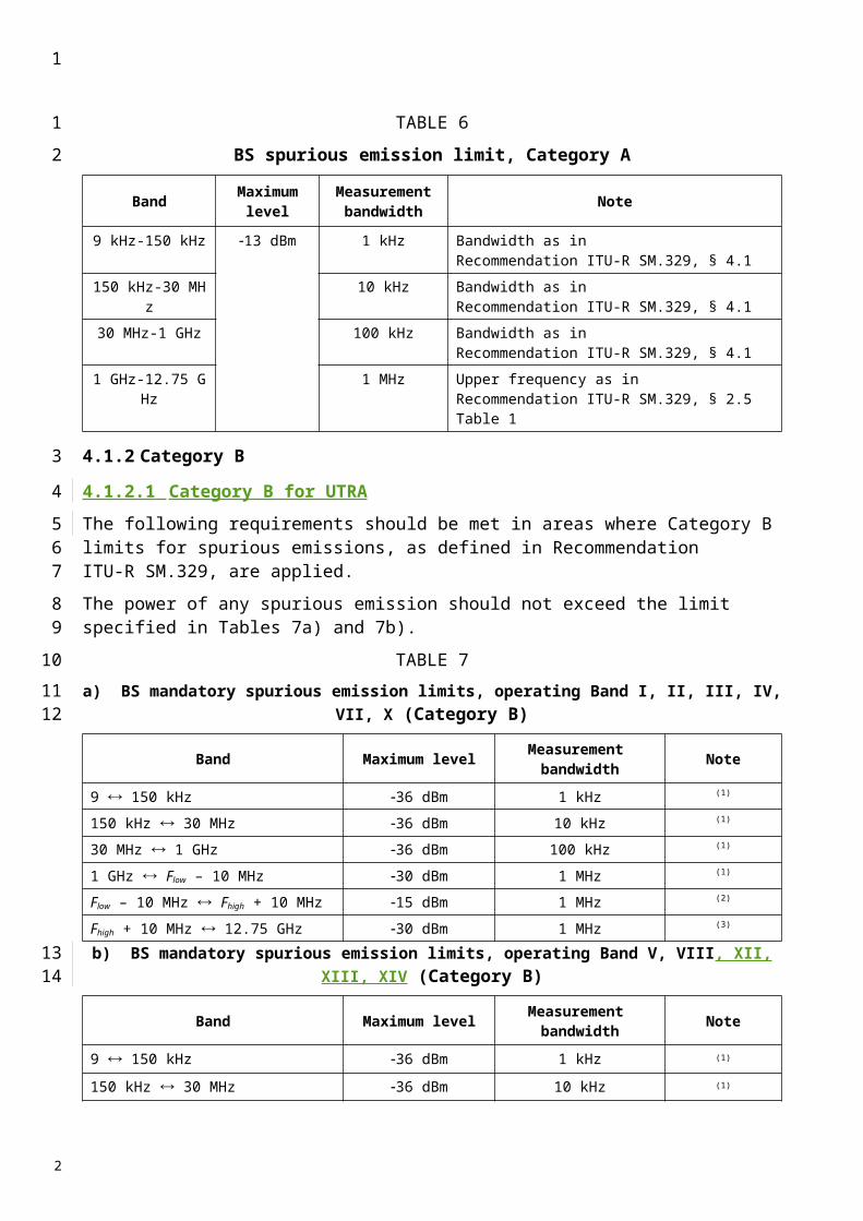
TABLE 1
Band Classes 0, 2, 5, 7, 9, and 10 Spectrum Emission Mask Values
For |Δf | within the Range Active Carriers Emission Limit
750 kHz to 1.98 MHz Single 45 dBc/30 kHz
1.98 to 4.00 MHz Single
-60 dBc / 30 kHz, HRPD-60 dBc / 30 kHz; Pout 33 dBm, cdma2000-27 dBm / 30 kHz; 28 dBm Pout < 33 dBm, cdma2000-55 dBc / 30 kHz; Pout < 28 dBm, cdma2000
3.25 to 4.00 MHz(Band Class 7 only) All 46 dBm / 6.25 kHz
NOTE 1 – All frequencies in the measurement bandwidth shall satisfy the restrictions on |Δf | where Δf centre frequency – closer edge frequency ( f ) of the measurement filter. For multiple-carrier testing, f is defined for positive f as the centre frequency of the highest carrier – closer measurement edge frequency ( f ) and for negative f as the centre frequency of the lowest carrier – closer measurement edge frequency ( f ).
The spectrum emission mask values in Table 2 apply to Band Classes 1, 4, 6, 8, 13, 14, and 15 and shall be met when transmitting on a single or all RF carriers supported by the BS as indicated by the entries in the column Active Carriers.
TABLE 2
Band Classes 1, 4, 6, 8, 13, 14, and 15 Spectrum Emission Mask Values
For | Δf| within the Range Active Carriers Emission Limit
885 kHz to 1.25 MHz Single -45 dBc / 30 kHz
1.25 to 1.98 MHz Single More stringent of -45 dBc / 30 kHz or -9 dBm / 30 kHz
1.25 to 2.25 MHz(MC tests only) All -9 dBm / 30 kHz
1.25 to 1.45 MHz (Band Classes 6 , 8, and 13) All -13 dBm / 30 kHz
1.45 to 2.25 MHz (Band Classes 6 , 8, and 13) All -[13 + 17 (f – 1.45 MHz)] dBm / 30 kHz
1.98 MHz to 2.25 MHz Single
-55 dBc / 30 kHz, HPRD -55 dBc / 30 kHz; Pout 33 dBm, cdma2000-22 dBm / 30 kHz; 28 dBm Pout < 33 dBm, cdma2000-50 dBc / 30 kHz; Pout < 28 dBm, cdma2000
2.25 MHz to 4.00 MHz All -13 dBm / 1 MHz
NOTE - All frequencies in the measurement bandwidth shall satisfy the restrictions on |f|. The emissions requirements shall apply for all values of f regardless of whether the measurement frequency falls inside or outside of the band or block edge. For single-carrier testing, f = center frequency - closer measurement edge frequency (f). For multiple-carrier testing, f is defined for positive f as the closer measurement edge frequency (f) - center frequency of the highest carrier and for negative f as the closer measurement edge frequency (f) - center frequency of the lowest carrier.
1
1
2
345
6
7
89
1011121314
2
The spectrum emission mask values in Table 3 apply to Band Classes 11 and 12 and shall be met when transmitting on a single or all RF carriers supported by the BS as indicated by the entries in the column Active Carriers.
TABLE 3
Band Classes 11 and 12 Spectrum Emission Mask Values
For |f| within the Range Active Carriers
Emission Limit
750 to 885 KHz Single -45-15(|f|-750)/135 dBc in 30 kHz885 to 1125 KHz Single -60-5(|f|-885)/240 dBc in 30 kHz
1.125 to 1.98 MHz Single -65 dBc / 30kHz1.98 to 4.00 MHz Single -75 dBc / 30kHz
NOTE - All frequencies in the measurement bandwidth shall satisfy the restrictions on |f| where f = center frequency - closer measurement edge frequency (f). f is positive offset from the highest valid CDMA channel in the band subclass or negative offset from the lowest valid CDMA channel in the band subclass. The emission limits for Band Classes 11 and 12 (European PAMR bands) are designed to allow co-existence with incumbent services in Europe and are tighter than ITU Category B requirements.
The spectrum emission mask values in Table 4 apply to Band Class 3 and should shall be met when transmitting on a single or all RF carriers supported by the BS as indicated by the entries in the column Active carriers.
1
123
4
5
6
789
2
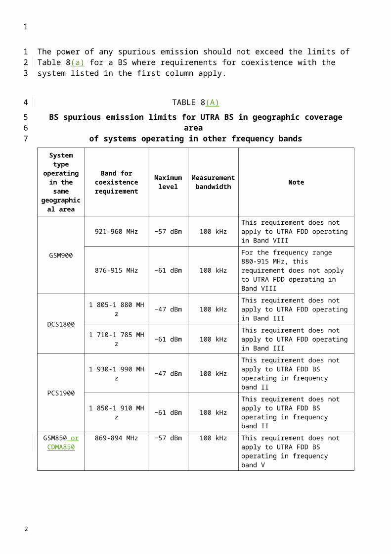
TABLE 4
Band Class 3 Spectrum Emission Mask Values
Measurement Frequency
Active Carriers
For | Δf | within the
RangeEmission Limit
> 832 MHz and Error! Objects cannot be created from editing field codes.834 MHz,> 838 MHz and Error! Objects cannot be created from editing field codes.846 MHz,> 860 MHz and Error! Objects cannot be created from editing field codes. 895 MHz
Single
Error! Objects cannot be created from editing field codes. 750 kHzand < 1.98 MHz
-45 dBc / 30 kHz
Single
Error! Objects cannot be created from editing field codes. 1.98 MHz
25 mW (-16 dBm) / 100 kHz; Pout Error! Objects cannot be created from editing field codes. 30 dBm-60 dBc / 100 kHz; 30dBm < Pout Error! Objects cannot be created from editing field codes. 47 dBmLess stringent of 50 mW (-13 dBm) / 100 kHz or -70 dBc / 100 kHz; Pout > 47 dBm
> 810 MHz and Error! Objects cannot be created from editing field codes. 860 MHz, except> 832 MHz and Error! Objects cannot be created from editing field codes. 834 MHz,> 838 MHz and Error! Objects cannot be created from editing field codes. 846 MHz
Single < 1.98 MHz
25 mW (-16 dBm) / 30 kHz; Pout Error! Objects cannot be created from editing field codes. 30 dBmMore stringent of -60 dBc / 30 kHz and 25 mW (-16 dBm) / 30 kHz; Pout > 30 dBm
Single
Error! Objects cannot be created from editing field codes. 1.98 MHz
25 mW (-16 dBm) / 100 kHz; Pout Error! Objects cannot be created from editing field codes. 30 dBmMore stringent of -60 dBc / 100 kHz and 25 mW (-16 dBm) / 100 kHz; Pout > 30 dBm
Error! Objects cannot be created from editing field codes. 810 MHzand > 895 MHz
All N/A
25 mW (-16 dBm) / 1 MHz; Pout Error! Objects cannot be created from editing field codes. 44 dBm-60 dBc / 1 MHz; 44 dBm < Pout Error! Objects cannot be created from editing field codes. 47 dBmLess stringent of 50 mW (-13 dBm) / 1 MHz or -70 dBc / 1 MHz; Pout > 47 dBm
NOTE - All frequencies in the measurement bandwidth shall satisfy the restrictions on |Δf|. The emissions requirements shall apply for all values of Δf regardless of whether the measurement frequency falls inside or outside of the band or block edge. For single-carrier testing, Δf = center frequency - closer measurement edge frequency (f). For multiple-carrier testing, Δf is defined for positive Δf as the closer measurement edge frequency (f) - center frequency of the highest carrier and for negative Δf as the closer measurement edge frequency (f) - center frequency of the lowest carrier.
1
1
2
2

The upper and lower limits of the frequency measurement are currently 10 MHz and 3 GHz in Japan radio measurement documents.
2 Transmitter Spurious Emission
In areas where Category A limits for spurious emissions, as defined in Recommendation ITU-R SM.329, are applied, the spurious emissions when transmitting on all RF carriers supported by the BS and configured in accordance with the manufacturer’s specification should shall be less than the limits specified in Tables 10a)5A and 10b)5B.
1
1
2345
2

TABLE 105A
a) BS spurious Spurious eEmission lLimits, Category A
For |Δf | within the Range Emission Limit
4.00 MHz
9 kHz f 150 kHz150 kHz f 30 MHz30 MHz f 1 GHz
1 GHz f 12.75 GHz
13 dBm/1 kHz13 dBm/10 kHz13 dBm/100 kHz13 dBm/1 MHz
NOTE 1 – All frequencies in the measurement bandwidth shall satisfy the restrictions on |Δf | where f centre frequency – closer edge frequency ( f ) of the measurement filter. For multiple-carrier testing, f is defined for positive f as the centre frequency of the highest carrier – closer measurement edge frequency ( f ) and for negative f as the centre frequency of the lowest carrier – closer measurement edge frequency ( f ).
TABLE 10 (END)5B
b) Additional transmitter sSpurious eEmission limits Limits in addition to Category A limits Limits in areas Areas where PHS is deployedDeployed
Measurement frequencyFrequency Measurement Bbandwidth Emission
limitLimitFor protection Protection of
1 893884.5 to 1 919.6 MHz 300 kHz 41 dBm PHS
1884.5 In areas where Category B limits for spurious emissions, as defined in Recommendation ITU-R SM.329, are applied, the spurious emissions when transmitting on a single or all RF carriers supported by the BS and configured in accordance with the manufacturer’s specification shouldshall be less than the limits specified in Tables 11a)6A and 11b)6B. The emission limits in Table 11a)6A shouldshall be met when transmitting on all RF carriers supported by the BS. The emission limits in Table 11b)6B shouldshall be met when transmitting on a single or all RF carriers supported by the BS as indicated by the entries in the column Active carriersCarriers.
TABLE 116A
a) Transmitter sSpurious eEmission lLimits, Category B
For |Δf | within the Range Emission Limit
4.00 MHz
9 kHz f 150 kHz150 kHz f 30 MHz30 MHz f 1 GHz
1 GHz f 12.75 GHz
36 dBm/1 kHz36 dBm/10 kHz36 dBm/100 kHz30 dBm/1 MHz
NOTE 1 – All frequencies in the measurement bandwidth shall satisfy the restrictions on |Δf | where f centre frequency – closer edge frequency ( f ) of the measurement filter. For multiple-carrier testing, f is defined for positive f as the centre frequency of the highest carrier – closer measurement edge frequency ( f ) and for negative f as the centre frequency of the lowest carrier – closer measurement edge frequency ( f ).
1
1
2
3
45
6789
101112
13
14
2
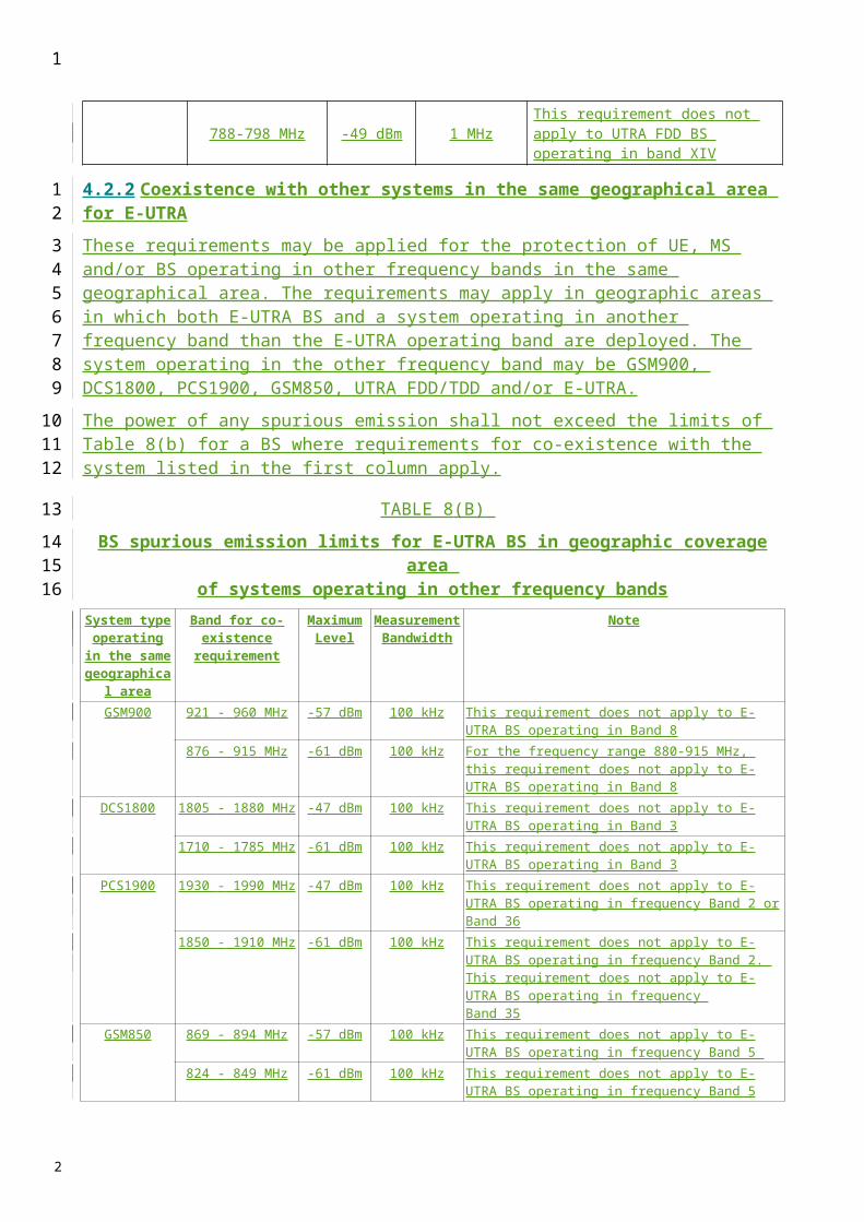
TABLE 6B
b) Additional transmitter sSpurious eEmission limits Limits in addition to Category B limitsLimits
Measurement frequencyFrequency
Active carriersCa
rriersEmission limitLimit For protection Protection
of
921 to 960 MHz All 57 dBm/100 kHz GSM 900 MS receive band1 805 to 1 880 MHz All 47 dBm/100 kHz DCS 1800 MS receive band1 900 to 1 920 MHz2 010 to 2 025 MHz All 52 dBm/1 MHz IMT-2000 CDMA TDD
1 920 to 1 980 MHz Single 86 dBm/1 MHz FDD BS receive band
When transmitting in Band Classes 0, 7, 9, and 10, the spurious emissions shall be less than the limits specified in Table 7A and 7B when transmitting on a single or all RF carriers supported by the BS as indicated by the entries in the column Active carriers.
TABLE 7A
Additional Band Classes 0, 7, 9, and 10 Spurious Emission Limits for ITU Category B only
For | Δf | within the Range
Active Carriers Emission Limit
> 4.00 MHz[Band Classes 0, 7, 9, and 10](ITU Category B only)
All
-36 dBm / 1 kHz;-36 dBm / 10 kHz;-36 dBm / 100 kHz;-30 dBm / 1 MHz;
9 kHz < f < 150 kHz150 kHz < f < 30 MHz30 MHz < f < 1 GHz 1 GHz < f < 12.5 GHz
TABLE 7B
Additional Band Classes 0, 7, 9, and 10 Spurious Emission Limits for ITU Category B only
Frequency Range Active Carriers Emission Limit
30 MHz < f < flow – 4.0 MHz All -36 dBm/100 kHzflow – 4.0 MHz Error! Objects cannot be created from editing field codes. f Error! Objects cannot be created from editing field codes. fc – 4.0 MHz
All -16 dBm/100 kHz
Fc + 4.0 MHz Error! Objects cannot be created from editing field codes. f Error! Objects cannot be created from editing field codes. fhigh + 4.0 MHz
All -16 dBm/100 kHz
fhigh + 4.0 MHz < f < 1.0 GHz All -36 dBm/100 kHzflow = The center frequency of the lowest valid carrier in the bandfhigh = The center frequency of the highest valid carrier in the band
1
1
23
456
7
8
9
10
2

When transmitting in Band Classes 2 and 5, the spurious emissions shall be less than the limits specified in Table 8 when transmitting on a single or all RF carriers supported by the BS as indicated by the entries in the column Active carriers.
TABLE 8
Additional Band Classes 2 and 5 Spurious Emission Limits for ITU Category B only
For | Δf | within the Range
Active Carriers Emission Limit
> 4.00 MHz[Band Classes 2 and 5](ITU Category B only)
All-36 dBm / 1 kHz;-36 dBm / 10 kHz; -30 dBm / 1 MHz;
9 kHz < f < 150 kHz150 kHz < f < 30 MHz1 GHz < f < 12.5 GHz
4.00 to 6.40 MHz(Band Classes 2 and 5)(ITU Category B only)
All -36 dBm / 1 kHz 30 MHz < f < 1 GHz
6.40 to 16 MHz(Band Classes 2 and 5)(ITU Category B only)
All -36 dBm / 10 kHz 30 MHz < f < 1 GHz
> 16 MHz(Band Classes 2 and 5)(ITU Category B only)
All -36 dBm / 100 kHz 30 MHz < f < 1 GHz
When transmitting in Band Classes 11 and 12, the spurious emissions shall be less than the limits specified in Tables 9A and 9B.
TABLE 9A
Additional Band Classes 11 and 12 Spurious Emission Limits for ITU Category B only
For | Δf| within the Range Active Carriers Emission Limit
> 6.00 MHz All
-36 dBm / 1 kHz;-36 dBm / 10 kHz;-45 dBm/100 kHz;-30 dBm / 1 MHz;
9 kHz < f < 150 kHz150 kHz < f < 30 MHz30 MHz < f < 1 GHz1 GHz < f < 12.75 GHz
TABLE 9B
Additional Band Classes 11 and 12 Spurious Emission Limits
For | Δf | within the Range Active Carriers Emission Limit
4.00 to 6.00 MHz All -36 dBm / 100kHz> 6.00 MHz All -45 dBm / 100kHzThe emission limits for Band Classes 11 and 12 (European PAMR bands) are designed to allow co-existence with incumbent services in Europe and are tighter than ITU Category B requirements.
1
123
4
5
67
8
9
10
11
2
When transmitting in Band Classes 1, 4, 6, 8, 13, 14, and 15, the spurious emissions shall be less than the limits specified in Table 10A. When transmitting in Band Class 6, the spurious emissions shall be less than the limits specified in Table 10B.
TABLE 10A
Additional Band Classes 1, 4, 6, 8, 13, 14, and 15 Spurious Emission Limits for ITU Category B only
Frequency Range Active Carriers Emission Limitflow – 4.0 MHz < f < fc – 4.0 MHz All -30 dBm/30 kHzfc + 4.0 MHz < f < fhigh + 4.0 MHz All -30 dBm/30 kHz
1 GHz < f < flow – 4.0 MHz All -30 dBm/1 MHz fhigh + 4.0 MHz < f < 12.5 GHz All -30 dBm/1 MHz
flow = The center frequency of the lowest valid carrier in the bandfhigh = The center frequency of the highest valid carrier in the band.
TABLE 10B
Additional Band Class 6 Spurious Emission Limits
Measurement Frequency
Active Carriers Emission Limit
When Coverage Overlaps
with1 884.5 to 1 919.6 MHz Single -41 dBm / 300 kHz PHS
824 to 849 MHz No -98 dBm / 100 kHz (co-located only)-61 dBm / 100 kHz (non-colocated)
GSM 850CDMA 850
869 to 894 MHz Yes –57 dBm / 100 kHz GSM 850CDMA 850
876 to 915 MHz Single –98 dBm / 100 kHz (co-located only)–61 dBm / 100 kHz (non-co-located) GSM 900
921 to 960 MHz All -57 dBm / 100 kHz GSM 900
1 710 to 1 785 MHz Single –98 dBm / 100 kHz (co-located only)–61 dBm / 100 kHz (non-co-located) DCS 1800
1 805 to 1 880 MHz All – 47 dBm / 100 kHz DCS 1800
1 900 to 1 920 MHz and2 010 to 2 025 MHz Single – 86 dBm / 1 MHz (co-located only) UTRA-TDD
1 900 to 1 920 MHz and2 010 to 2 025 MHz All –52 dBm / 1 MHz UTRA-TDD
1 920 to 1 980 MHz Single – 86 dBm / 1 MHz Always
When transmitting in Band Class 10 in North America the spurious emissions shall be less than the limits specified in Table 11.
1
123
4
56
7
8
910
2
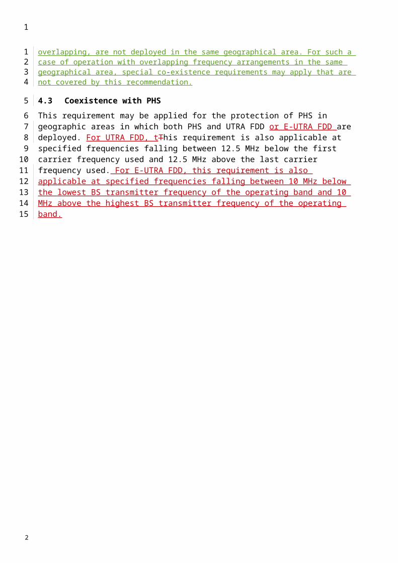
TABLE 11
Additional Band Class 10 Spurious Emission Limits for North American Operation
Measurement Frequency Emission Limit
854.75 to 861 MHz -40 dBm / 30 kHz866 to 869 MHz -40 dBm / 30 kHz
NOTE - The Band Class 10 spurious emissions limit is designed to allow marginal co-existence with North American PMRS 800 MHz Public Safety services and is far tighter than the CFR 47 Part 90.691(a)(2) requirement.
When transmitting in Band Class 7, the spurious emissions shall also be less than the limits specified in Table 12.
TABLE 12
Additional Band Class 7 Spurious Emission LimitsTransmission
Frequency (MHz)Measurement Frequency
(MHz)Emission Limit Victim Band
746-758 763-775 and 793-805 -46 dBm/6.25 kHz Public Safety758-768 769-775 and 799-805 -46 dBm/6.25 kHz Public Safety
3 Adjacent Channel Leakage Power Ratio
For cdma2000 adjacent channel leakage power ratio (ACLR) calculation, both the transmitted power and received power are measured with a rectangular filter. For cdma2000 system, the first adjacent channel offset is 2.5 MHz and the second adjacent channel offset is 3.75 MHz for band classes in 1900 MHz. For cellular band in 800 or 450 MHz, the first adjacent channel offset is 1.5 MHz and the second adjacent channel offset is 2.73 MHz. The receiver bandwidth is 1.23 MHz.
The limit for ACLR should be as specified in Table 13.
TABLE 13
Base Station ACLR LimitsBand Class ACLR1 (dB) ACLR2 (dB)
0 29.36 43.871 42.96 55.562 29.36 43.874 42.96 55.565 29.36 43.876 52.89 55.567 29.36 44.228 52.89 55.569 29.36 43.87
10 29.36 43.8711 48.57 58.8712 48.57 58.8713 52.89 55.5614 42.96 55.56
1
1
2
34
5
6
7
89
101112
13
14
15
2
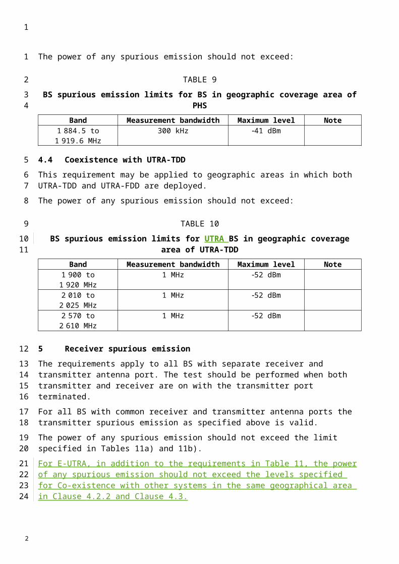
15 42.96 55.56For cdma2000 system, the first adjacent channel offset is
2.5 MHz (ACLR1) and the second adjacent channel offset is 3.75 MHz for band classes in 1900 MHz (ACLR2). For
cellular band in 800 or 450 MHz, the first adjacent channel offset is 1.5 MHz (ACLR1) and the second adjacent channel
offset is 2.73 MHz (ACLR2)
343 Receiver spurious Spurious emissionEmission
This requirement only applies if the BS is equipped with a separate RF input port. The conducted spurious emissions at the BS RF input ports should shall be not greater than the limits in Tables 12 143 and 13154.
TABLE 12143
General rReceiver spurious Spurious emission Emission requirementsRequirements
Frequency Band MeasurementBandwidth
Maximum Level Note
30 MHz f 1 GHz 100 kHz 57 dBm
1 GHz f 12.75 GHz 1 MHz 47 dBm
With the exception of the frequencies covered by Table 15, for which additional receiver spurious emission requirements apply
For all frequencies within the mobile station receive and transmit bands, the conducted emissions shall be below the limits in Table 154.
TABLE 13154
Additional receiver Receiver spurious Spurious emission Emission requirementsRequirements
Frequency bandMeasurementbandwidthBandwidth (kHz)
Maximum levelLevel (dBm)
Note
1 920 MHz f 1 980 MHz
30 kHz 80 dBm Base receive band
2 110 MHz f 2 170 MHz
30 kHz 60 dBm Base transmit band
1
1
234
5
6
78
9
1011
2

Annex 3
IMT-2000 CDMA TDD (UTRA TDD) base stations
1 Measurement uncertainty
Values specified in this Annex differ from those specified in Recommendation ITU-R M.1457 since values in this Annex incorporate test tolerances defined in Recommendation ITU-R M.1545.
2 Spectrum mask
2.1 UTRA 3.84 Mchip/s TDD option
The spectrum emission mask specifies the limit of the transmitter OoB emissions at frequency offsets from the assigned channel frequency of the wanted signal between 2.5 MHz and 12.5 MHz.
The requirement should be met by a BS transmitting on a single RF carrier configured in accordance with the manufacturer’s specification. Emissions should not exceed the maximum level specified in Tables 17a to 20a in the frequency range of f_offset from 2.515 MHz to fmax from the carrier frequency, where:– f_offset is the separation between the carrier frequency and the centre of the measurement
filter: f_offsetmax is either 12.5 MHz or the offset to the universal mobile telecommunications
system (UMTS) transmit band edge (uplink and downlink transmission in the following bands: 1 900-1 920 MHz and 2 010-2 025 MHz, 1 850-1 910 MHz and 1 930-1 990 MHz used in ITU Region 2, 1 910-1 930 MHz used in ITU Region 2, 2 570-2 620 MHz used in ITU Region 1), whichever is the greater.
fmax is equal to f_offsetmax minus half of the bandwidth of the measuring filter.
The spectrum emissions measured should not exceed the maximum level specified in Tables 17a to 20a for the appropriate BS rated output power.
TABLE 17A
Spectrum emission mask values, BS maximum output power P 43 dBm
Frequency offset of measurement filter
−3 dB point, f
Frequency offset of measurement filter centre frequency,
f_offset
Maximum levelMeasure-
ment bandwidth
2.5 MHz f < 2.7 MHz 2.515 MHz f_offset < 2.715 MHz −12.5 dBm 30 kHz
2.7 MHz f < 3.5 MHz 2.715 MHz f_offset < 3.515 MHz 30 kHz
(see Note) 3.515 MHz f_offset < 4.0 MHz −24.5 dBm 30 kHz
3.5 MHz f fmax 4.0 MHz f_offset −11.5 dBm 1 MHz
1
123
4
56
7
8
910
111213141516171819202122
2324
25
26
2
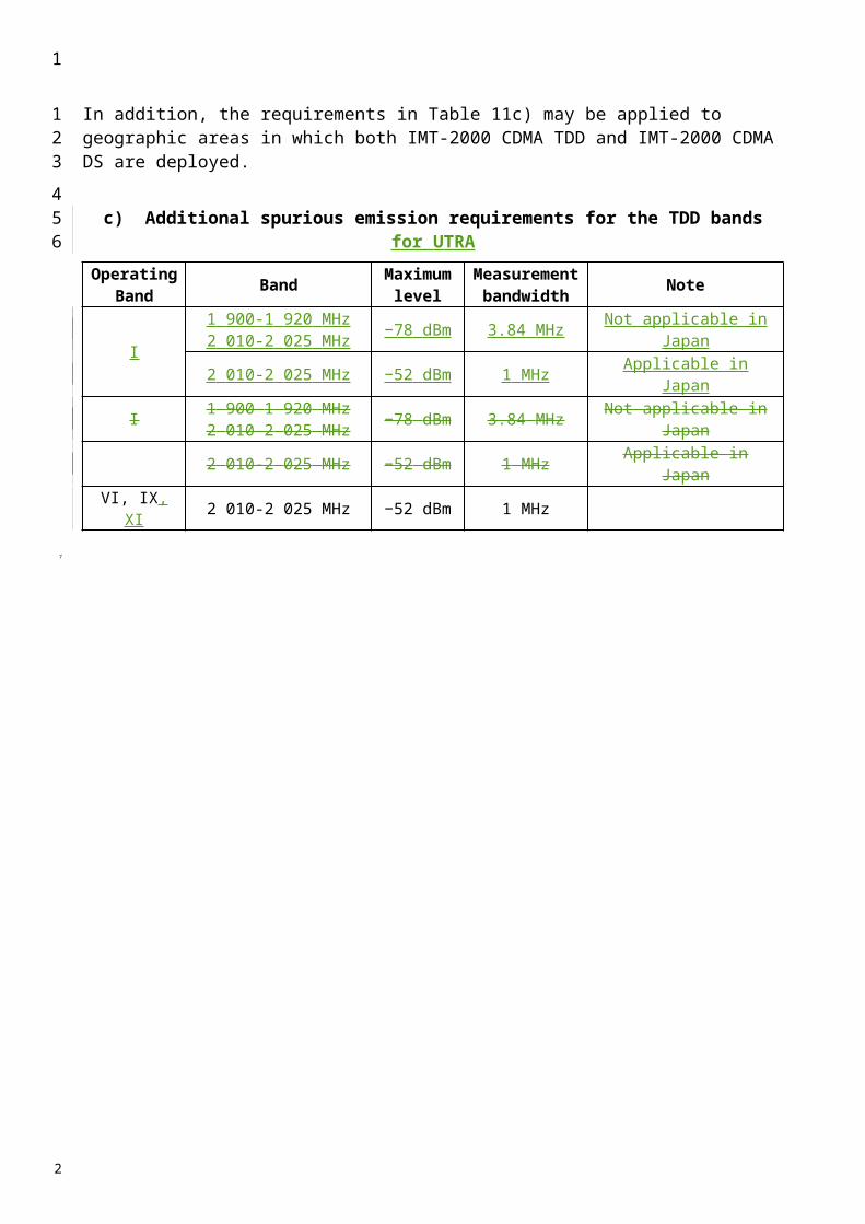
< f_offsetmax
TABLE 18A
Spectrum emission mask values, BS maximum output power 39 P < 43 dBm
Frequency offset of measurement filter
−3 dB point, f
Frequency offset of measurement filter centre frequency,
f_offset
Maximum levelMeasure-
ment bandwidth
2.5 MHz f < 2.7 MHz 2.515 MHz f_offset < 2.715 MHz −12.5 dBm 30 kHz
2.7 MHz f < 3.5 MHz 2.715 MHz f_offset < 3.515 MHz 30 kHz
(see Note) 3.515 MHz f_offset < 4.0 MHz −24.5 dBm 30 kHz
3.5 MHz f < 7.5 MHz 4.0 MHz f_offset < 8.0 MHz −11.5 dBm 1 MHz
7.5 MHz f fmax8.0 MHz f_offset
< f_offsetmaxP – 54.5 dB 1 MHz
TABLE 19A
Spectrum emission mask values, BS maximum output power 31 P < 39 dBm
Frequency offset of measurement filter −3 dB
point, f
Frequency offset of measurement filter centre frequency,
f_offset
Maximum levelMeasure-
ment bandwidth
2.5 MHz f < 2.7 MHz 2.515 MHz f_offset < 2.715 MHz P – 51.5 dB 30 kHz
2.7 MHz f < 3.5 MHz 2.715 MHz f_offset < 3.515 MHz 30 kHz
(see Note) 3.515 MHz f_offset < 4.0 MHz P – 63.5 dB 30 kHz
3.5 MHz f < 7.5 MHz 4.0 MHz f_offset < 8.0 MHz P – 50.5 dB 1 MHz
7.5 MHz f fmax8.0 MHz f_offset
< f_offsetmaxP – 54.5 dB 1 MHz
1
1
2
3
4
5
2
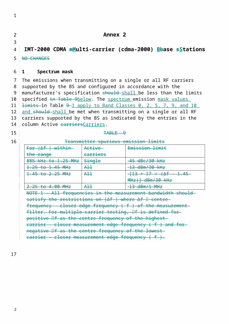
TABLE 20A
Spectrum emission mask values, BS maximum output power P < 31 dBm dB
Frequency offset of measurement filter −3 dB
point, f
Frequency offset of measurement filter centre frequency,
f_offset
Maximum levelMeasure-
ment bandwidth
2.5 MHz f < 2.7 MHz 2.515 MHz f_offset < 2.715 MHz −20.5 dBm 30 kHz
2.7 MHz f < 3.5 MHz 2.715 MHz f_offset < 3.515 MHz 30 kHz
(see Note) 3.515 MHz f_offset < 4.0 MHz −32.5 dBm 30 kHz
3.5 MHz f < 7.5 MHz 4.0 MHz f_offset < 8.0 MHz −19.5 dBm 1 MHz
7.5 MHz f fmax8.0 MHz f_offset
< f_offsetmax−23.5 dBm 1 MHz
NOTE – This frequency range ensures that the range of values of f_offset is continuous.
2.2 UTRA 1.28 Mchip/s TDD option
The spectrum emission mask specifies the limit of the transmitter OoB emissions at frequency offsets from the assigned channel frequency of the wanted signal between 0.8 MHz and 4.0 MHz.
The requirement should be met by a BS transmitting on a single RF carrier configured in accordance with the manufacturer’s specification. Emissions should not exceed the maximum level specified in Tables 17b21 to 19b23 in the frequency range of f_offset from 0.815 MHz to fmax from the carrier frequency, where:– f_offset is the separation between the carrier frequency and the centre of the measurement
filter: f_offsetmax is either 4.0 MHz or the offset to the universal mobile telecommunication system
(UMTS) transmit band edge (uplink and downlink transmission in the following bands: 1 900-1 920 MHz and 2 010-2 025 MHz, 1 850-1 910 MHz and 1 930-1 990 MHz used in ITU Region 2, 1 910-1 930 MHz used in ITU Region 2, 2 570-2 620 MHz used in ITU Region 1), whichever is the greater.
fmax is equal to f_offsetmax minus half of the bandwidth of the measuring filter.
The spectrum emissions measured should not exceed the maximum level specified in Tables 17b to 19b for the appropriate BS rated output power.
1
1
2
3
4
56
789
101112131415161718
1920
2

TABLE 17B
Spectrum emission mask values, BS maximum output power P 34 dBm
Frequency offset of measurement filter
−3 dB point, f
Frequency offset of measurement filter centre frequency,
f_offset
Maximum levelMeasure-
ment bandwidth
0.8 MHz f < 1.0 MHz 0.815 MHz f_offset < 1.015 MHz −18.5 dBm 30 kHz
1.0 MHz f < 1.8 MHz 1.015 MHz f_offset < 1.815 MHz 30 kHz
(see Note) 1.815 MHz f_offset < 2.3 MHz −26.5 dBm 30 kHz
1.8 MHz f fmax2.3 MHz f_offset
< f_offsetmax−11.5 dBm 1 MHz
TABLE 18B
Spectrum emission mask values, BS maximum output power 26 P < 34 dBm
Frequency offset of measurement filter −3 dB
point, f
Frequency offset of measurement filter centre frequency,
f_offset
Maximum levelMeasure-
ment bandwidth
0.8 MHz f < 1.0 MHz 0.815 MHz f_offset < 1.015 MHz P − 52.5 dB 30 kHz
1.0 MHz f < 1.8 MHz 1.015 MHz f_offset < 1.815 MHz 30 kHz
(see Note) 1.815 MHz f_offset < 2.3 MHz P − 60.5 dB 30 kHz
1.8 MHz f fmax2.3 MHz f_offset
< f_offsetmaxP – 45.5 dB 1 MHz
TABLE 19B
Spectrum emission mask values, BS maximum output power P < 26 dBm
Frequency offset of measurement filter
−3 dB point, f
Frequency offset of measurement filter centre frequency,
f_offset
Maximum levelMeasure-
ment bandwidth
0.8 MHz f < 1.0 MHz 0.815 MHz f_offset < 1.015 MHz −26.5 dBm 30 kHz
1.0 MHz f < 1.8 MHz 1.015 MHz f_offset < 1.815 MHz 30 kHz
(see Note) 1.815 MHz f_offset < 2.3 MHz −34.5 dBm 30 kHz
1.8 MHz f fmax2.3 MHz f_offset
< f_offsetmax−19.5 dBm 1 MHz
1
1
2
3
4
5
6
2
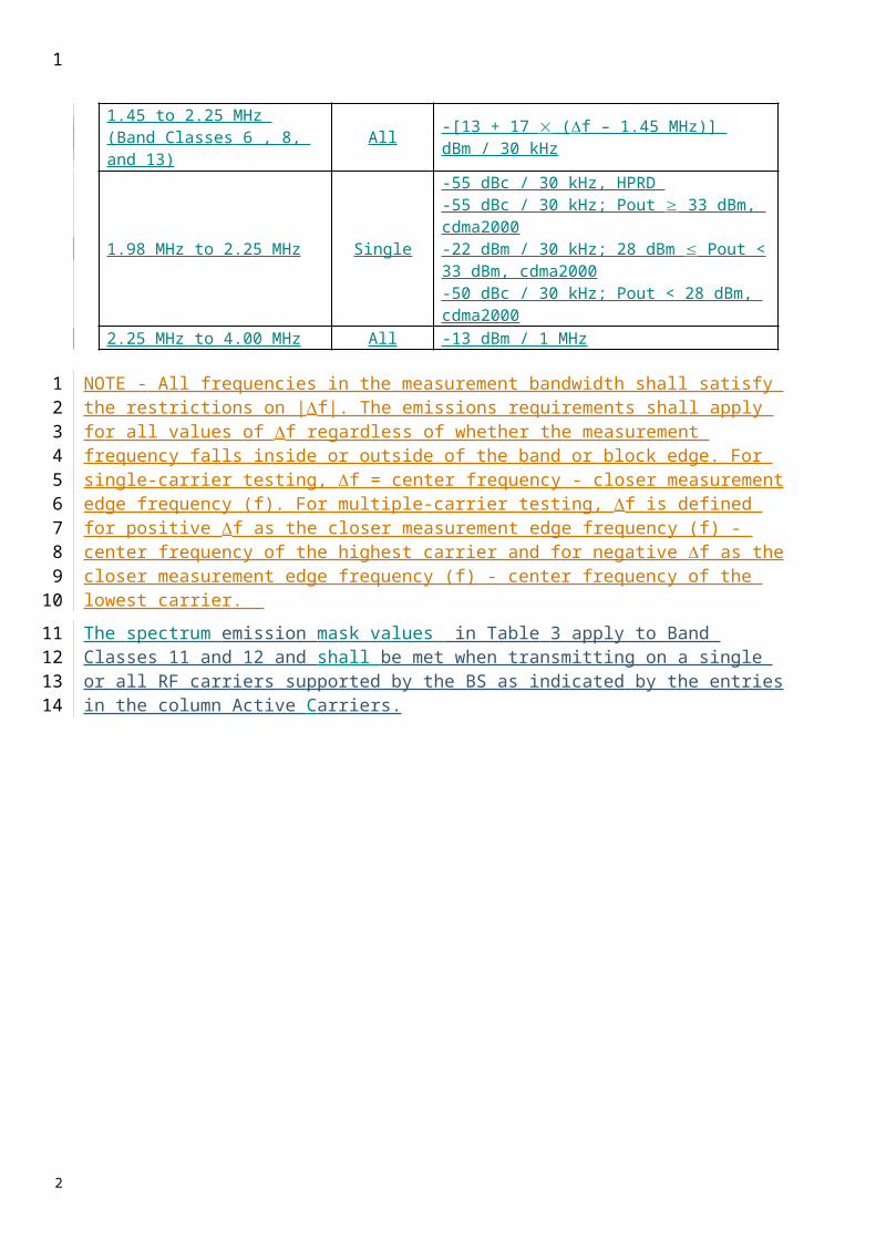
NOTE – This frequency range ensures that the range of values of f_offset is continuous.
2.3 UTRA 7.68 Mchip/s TDD option
The spectrum emission mask specifies the limit of the transmitter OoB emissions at frequency offsets from the assigned channel frequency of the wanted signal between 5 MHz and 25 MHz.
The requirement should be met by a BS transmitting on a single RF carrier configured in accordance with the manufacturer’s specification. Emissions should not exceed the maximum level specified in Tables 17c20 to 20c23 in the frequency range of f_offset from 5.015 MHz to fmax from the carrier frequency, where:– f_offset is the separation between the carrier frequency and the centre of the measurement
filter: f_offsetmax is either 25 MHz or the offset to the universal mobile telecommunications
system (UMTS) transmit band edge (uplink and downlink transmission in the following bands: 1 900-1 920 MHz and 2 010-2 025 MHz, 1 850-1 910 MHz and 1 930-1 990 MHz used in ITU Region 2, 1 910-1 930 MHz used in ITU Region 2, 2 570-2 620 MHz used in ITU Region 1), whichever is the greater.
fmax is equal to f_offsetmax minus half of the bandwidth of the measuring filter.
The spectrum emissions measured should not exceed the maximum level specified in Tables 17c to 19c for the appropriate BS rated output power.
TABLE 17CSpectrum emission mask values, BS maximum output power P 43 dBm
Frequency offset of measurement filter −3 dB
point, f
Frequency offset of measurement filter centre frequency,
f_offset
Maximum level Measurement bandwidth
5 MHz f < 5.2 MHz 5.015 MHz f_offset < 5.215 MHz −15.5 dBm 30 kHz
5.2 MHz f < 6 MHz 5.215 MHz f_offset < 6.015 MHz 30 kHz
(see Note) 6.015 MHz f_offset < 6.5 MHz −27.5 dBm 30 kHz
6 MHz f fmax6.5 MHz f_offset
< f_offsetmax−14.5 dBm 1 MHz
TABLE 18CSpectrum emission mask values, BS maximum output power 39 P < 43 dBm
Frequency offset of measurement filter −3 dB
point, f
Frequency offset of measurement filter centre frequency,
f_offset
Maximum level Measurement bandwidth
5 MHz f < 5.2 MHz 5.015 MHz f_offset < 5.215 MHz −15.5 dBm 30 kHz
5.2 MHz f < 6 MHz 5.215 MHz f_offset < 6.015 MHz 30 kHz
(see Note) 6.015 MHz f_offset < 6.5 MHz −27.5 dBm 30 kHz
6 MHz f < 15 MHz 6.5 MHz f_offset < 15.5 MHz −14.5 dBm 1 MHz
15 MHz f fmax15.5 MHz f_offset
< f_offsetmaxP – 57.5 dB 1 MHz
1
1
2
34
56789
10111213141516
1718
1920
2122
2

TABLE 19C
Spectrum emission mask values, BS maximum output power 31 P < 39 dBm
Frequency offset of measurement filter
−3 dB point, f
Frequency offset of measurement filter centre frequency,
f_offset
Maximum levelMeasure-
ment bandwidth
5 MHz f < 5.2 MHz 5.015 MHz f_offset < 5.215 MHz P – 54.5 dB 30 kHz
5.2 MHz f < 6 MHz 5.215 MHz f_offset < 6.015 MHz 30 kHz
(see Note) 6.015 MHz f_offset < 6.5 MHz P – 66.5 dB 30 kHz
6 MHz f < 15 MHz 6.5 MHz f_offset < 15.5 MHz P – 53.5 dB 1 MHz
15 MHz f fmax15.5 MHz f_offset
< f_offsetmaxP – 57.5 dB 1 MHz
TABLE 20C
Spectrum emission mask values, BS maximum output power P < 31 dBm
Frequency offset of measurement filter
−3 dB point, f
Frequency offset of measurement filter centre frequency,
f_offset
Maximum levelMeasure-
ment bandwidth
5 MHz f < 5.2 MHz 5.015 MHz f_offset < 5.215 MHz −23.5 dBm 30 kHz
5.2 MHz f < 6 MHz 5.215 MHz f_offset < 6.015 MHz 30 kHz
(see Note) 6.015 MHz f_offset < 6.5 MHz −35.5 dBm 30 kHz
6 MHz f < 15 MHz 6.5 MHz f_offset < 15.5 MHz −22.5 dBm 1 MHz
15 MHz f fmax15.5 MHz f_offset
< f_offsetmax−26.5 dBm 1 MHz
NOTE – This frequency range ensures that the range of values of f_offset is continuous.
2.4 E-UTRA (LTE) spectrum mask
The Operating band unwanted emission limits are defined from 10 MHz below the lowest frequency of the BS transmitter operating band up to 10 MHz above the highest frequency of the BS transmitter operating band.
The requirements shall apply whatever the type of transmitter considered (single carrier or multi-carrier) and for all transmission modes foreseen by the manufacturer's specification.
The unwanted emission limits in the part of the operating band that falls in the spurious domain are consistent with Recommendation ITU-R SM.329.
1
1
2
3
4
5
6
789
1011
1213
2
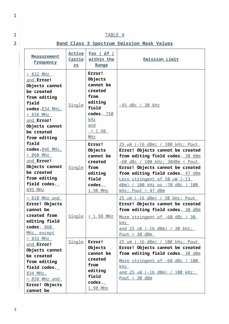
Emissions should not exceed the maximum level specified in Tables below, where:– f is the separation between the channel edge frequency and the nominal -3 dB point of the
measuring filter closest to the carrier frequency.– f_offset is the separation between the channel edge frequency and the centre of the
measuring filter.– f_offsetmax is the offset to the frequency 10 MHz outside the BS transmitter operating band.– fmax is equal to f_offsetmax minus half of the bandwidth of the measuring filter.
For a multicarrier E-UTRA BS the definitions above apply to the lower edge of the carrier transmitted at the lowest carrier frequency and the higher edge of the carrier transmitted at the highest carrier frequency.
The requirements of either § 2.4.1 or § 2.4.2 shall apply.
The Additional operating band unwanted emission limits defined in § 2.4.2.1 may be mandatory in certain regions. In other regions it may not apply.
2.4.1 E-UTRA spectrum mask (Category A)
For E-UTRA BS operating in TDD bands, emissions shall not exceed the maximum levels specified in Table 17d:
TABLE 17D
d-a) General operating band unwanted emission limits for 1.4 MHz channel bandwidth (E-UTRA bands >1 GHz) for Category A
Frequency offset of measurement filter
-3dB point, f
Frequency offset of measurement filter centre
frequency, f_offset
Minimum requirement Measurement bandwidth
(Note 1)
0 MHz f < 1.4 MHz 0.05 MHz f_offset < 1.45 MHz100 kHz
1.4 MHz f < 2.8 MHz
1.45 MHz f_offset < 2.85 MHz -9.5 dBm 100 kHz
2.8 MHz f fmax 2.85 MHz f_offset < f_offsetmax -13 dBm 100 kHz
d-b) General operating band unwanted emission limits for 3 MHz channel bandwidth (E-UTRA bands >1 GHz) for Category A
Frequency offset of measurement filter
-3dB point, f
Frequency offset of measurement filter centre
frequency, f_offset
Minimum requirement Measurement bandwidth
(Note 1)
0 MHz f < 3 MHz 0.05 MHz f_offset < 3.05 MHz100 kHz
3 MHz f < 6 MHz 3.05 MHz f_offset < 6.05 MHz -13.5 dBm 100 kHz 6 MHz f fmax 6.5 MHz f_offset < f_offsetmax -13 dBm 1MHz
d-c) General operating band unwanted emission limits for 5, 10, 15 and 20 MHz channel bandwidth (E-UTRA bands >1 GHz) for Category A
Frequency offset of measurement filter
-3dB point, f
Frequency offset of measurement filter centre
frequency, f_offset
Minimum requirement Measurement bandwidth
(Note 1)0 MHz f < 5 MHz 0.05 MHz f_offset < 5.05 MHz 100 kHz
5 MHz f < 10 MHz 5.05 MHz f_offset < 10.05 MHz -12.5 dBm 100 kHz 10 MHz f fmax 10.5 MHz f_offset < f_offsetmax -13 dBm 1MHz
1
1234567
89
10
11
1213
14
1516
17
1819
2021
2223
2

2.4.2 E-UTRA spectrum mask (Category B)
For E-UTRA BS operating in bands 33, 34, 35, 36, 37, 38,39 and 40, emissions shall not exceed the maximum levels specified in Table 18d:
TABLE 18D
d-a) General operating band unwanted emission limits for 1.4 MHz channel bandwidth (E-UTRA bands >1 GHz) for Category B
Frequency offset of measurement filter
-3dB point, f
Frequency offset of measurement filter centre
frequency, f_offset
Minimum requirement Measurement bandwidth
(Note 1)
0 MHz f < 1.4 MHz 0.05 MHz f_offset < 1.45 MHz100 kHz
1.4 MHz f < 2.8 MHz
1.45 MHz f_offset < 2.85 MHz -9.5 dBm 100 kHz
2.8 MHz f fmax 3.3 MHz f_offset < f_offsetmax -15 dBm 1MHz
d-b) General operating band unwanted emission limits for 3 MHz channel bandwidth (E-UTRA bands >1 GHz) for Category B
Frequency offset of measurement filter
-3dB point, f
Frequency offset of measurement filter centre
frequency, f_offset
Minimum requirement Measurement bandwidth
(Note 1)
0 MHz f < 3 MHz 0.05 MHz f_offset < 3.05 MHz100 kHz
3 MHz f < 6 MHz 3.05 MHz f_offset < 6.05 MHz -13.5 dBm 100 kHz 6 MHz f fmax 6.5 MHz f_offset < f_offsetmax -15 dBm 1MHz
d-c) General operating band unwanted emission limits for 5, 10, 15 and 20 MHz channel bandwidth (E-UTRA bands >1 GHz) for Category B
Frequency offset of measurement filter
-3dB point, f
Frequency offset of measurement filter centre
frequency, f_offset
Minimum requirement Measurement bandwidth
(Note 1)0 MHz f < 5 MHz 0.05 MHz f_offset < 5.05 MHz 100 kHz
5 MHz f < 10 MHz 5.05 MHz f_offset < 10.05 MHz -12.5 dBm 100 kHz 10 MHz f fmax 10.5 MHz f_offset < f_offsetmax -15 dBm 1MHz
2.4.2.1 E-UTRA spectrum mask (additional limits)
The following requirements may apply in certain regions. For E-UTRA BS operating bands 35, and 36, emissions shall not exceed the maximum levels specified in Table 19d.
1
1
2
34
5
67
8
910
11
1213
14
15
1617
2

TABLE 19D
Additional operating band unwanted emission limits for E-UTRA bands>1 GHzChannel
bandwidthFrequency offset of measurement filter
-3 dB point, f
Frequency offset of measurement filter centre
frequency, f_offset
Minimum requirement
Measurement bandwidth
(Note 1)
1.4 MHz0 MHz f < 1 MHz 0.005 MHz f_offset < 0.995
MHz -12.5 dBm 10 kHz
1 MHz f < 2.8 MHz 1.5 MHz f_offset < 3.3 MHz -11.5 dBm 1 MHz2.8 MHz f < fmax 3.3 MHz f_offset < f_offsetmax -13 dBm
3 MHz0 MHz f < 1 MHz 0.015 MHz f_offset < 0.985
MHz -11.5 dBm 30 kHz
1 MHz f < 6 MHz 1.5 MHz f_offset < 6.5 MHz -11.5 dBm 1 MHz6 MHz f < fmax 6.5 MHz f_offset < f_offsetmax -13 dBm
5 MHz0 MHz f < 1 MHz 0.015 MHz f_offset < 0.985
MHz -13.5 dBm 30 kHz
1 MHz f < 10 MHz 1.5 MHz f_offset < 10.5 MHz -11.5 dBm 1 MHz10 MHz f < fmax 10.5 MHz f_offset < f_offsetmax -13 dBm
10 MHz0 MHz f < 1 MHz 0.05 MHz f_offset < 0.95 MHz -11.5 dBm 100 kHz
1 MHz f < 20 MHz 1.5 MHz f_offset < 20.5 MHz -11.5 dBm 1 MHz20 MHz f < fmax 20.5 MHz f_offset < f_offsetmax -13 dBm
15 MHz0 MHz f < 1 MHz 0.05 MHz f_offset < 0.95 MHz -13.5 dBm 100 kHz
1 MHz f < 30 MHz 1.5 MHz f_offset < 30.5 MHz -11.5 dBm 1 MHz30 MHz f < fmax 30.5 MHz f_offset < f_offsetmax -13 dBm
20 MHz0 MHz f < 1 MHz 0.05 MHz f_offset < 0.95 MHz -14.5 dBm 100 kHz
1 MHz f < 40 MHz 1.5 MHz f_offset < 40.5 MHz -11.5 dBm 1 MHz40 MHz f < fmax 40.5 MHz f_offset < f_offsetmax -13 dBm
NOTE 1 – As a general rule for the requirements in section 2.4, the resolution bandwidth of the measuring equipment should be equal to the measurement bandwidth. However, to improve measurement accuracy, sensitivity and efficiency, the resolution bandwidth can be smaller than the measurement bandwidth. When the resolution bandwidth is smaller than the measurement bandwidth, the result should be integrated over the measurement bandwidth in order to obtain the equivalent noise bandwidth of the measurement bandwidth.
3 ACLR
ACLR is the ratio of the transmitted power to the power measured after a receiver filter in the adjacent channel(s).
3.1 ACLR for UTRA
For UTRA, Bboth the transmitted power and the received power are measured through a matched filter (root raised cosine and roll-off 0.22) with a noise power bandwidth equal to the chip rate. The requirements should apply whatever the type of transmitter considered (single carrier or multi-carrier). It applies for all transmission modes foreseen by the manufacturer’s specification.
The ACLR of a single carrier BS or a multi-carrier BS with contiguous carrier frequencies should be higher than the value specified in Tables 21a), 21b) and 21c).
1
1
2
345678
9
1011
12
13141516
1718
2
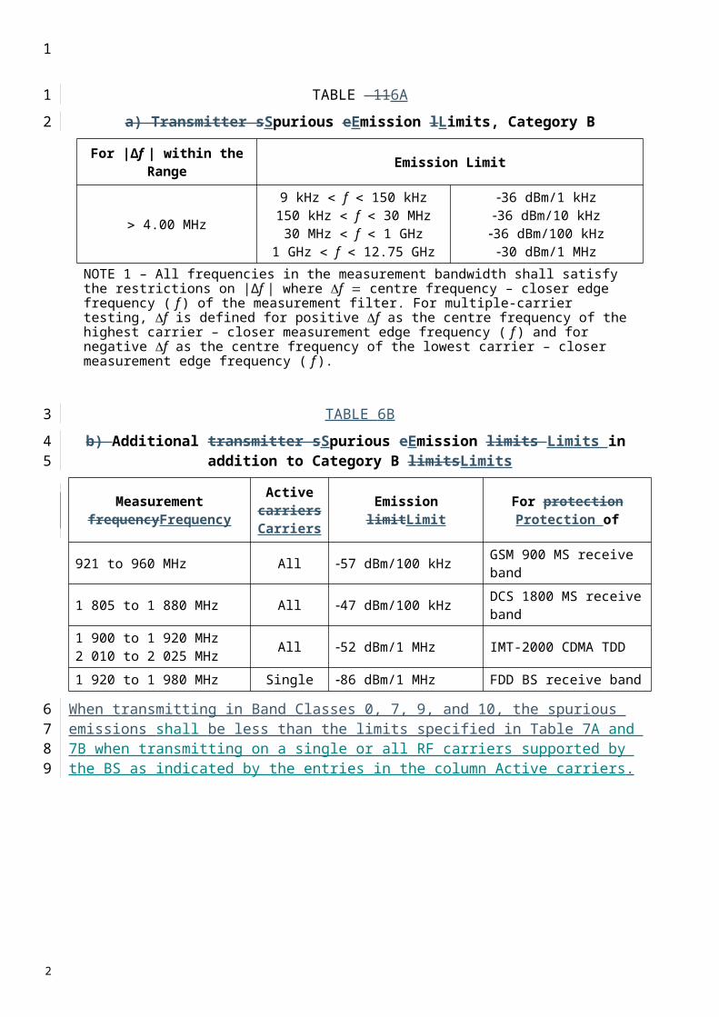
TABLE 21
a) BS ACLR limits for 3.84 Mchip/s TDD option
BS adjacent channel offset below the first or above the last carrier frequency used
(MHz)
ACLR limit(dB)
5 44.210 54.2
b) BS ACLR limits for 1.28 Mchip/s TDD option
BS adjacent channel offset below the first or above the last carrier frequency used
(MHz)
ACLR limit(dB)
1.6 39.23.2 44.2
c) BS ACLR limits for 7.68 Mchip/s TDD option
BS adjacent channel offset below the first or above the last carrier frequency used
(MHz)
Chip rate for RRC measurement filter
(Mchip/s)
ACLR limit(dB)
7.5 3.84 44.212.5 3.84 54.210.0 7.68 44.220.0 7.68 54.2
If a BS provides multiple non-contiguous single carriers or multiple non-contiguous groups of contiguous single carriers, the above requirements should be applied individually to the single carriers or group of single carriers.
3.2 ACLR for E-UTRA (LTE)
The ACLR is defined with a square filter of bandwidth equal to the transmission bandwidth configuration of the transmitted signal (BWConfig) centred on the assigned channel frequency and a filter centred on the adjacent channel frequency according to the tables below. The transmission bandwidth configuration is as specified in Table 21b.
1
1
2
34
56
7
89
10
11
12131415
2
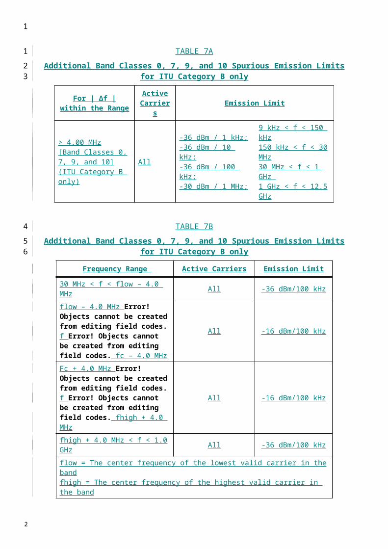
TABLE 21B
Downlink transmission bandwidth configuration BWConfig
Channel bandwidth BWChannel [MHz] 1.4 3 5 10 15 20
Transmission bandwidth configuration (BWConfig)
[MHz]1.095 2.715 4.515 9.015 13.515 18.015
For Category A limits in the tables below or the absolute limit of -13 dBm/MHz apply, whichever is less stringent.
For Category B, either the ACLR limits in the tables below or the absolute limit of -15 dBm/MHz apply, whichever is less stringent.
For operation in unpaired spectrum, the ACLR shall be higher than the value specified in Table 21c.
TABLE 21C
Base Station ACLR in unpaired spectrum with synchronized operationE-UTRA transmitted
signal channel bandwidth BWChannel [MHz]
BS adjacent channel centre frequency offset below the first or above the last carrier centre
frequency used
Assumed adjacent channel carrier (informative)
Filter on the adjacent channel frequency and
corresponding filter bandwidth
ACLR limit
1.4, 3.0 BWChannel E-UTRA of same BW Square (BWConfig) 44.2 dB2 x BWChannel E-UTRA of same BW Square (BWConfig) 44.2 dB
BWChannel /2 + 0.8 MHz 1.28 Mcps UTRA RRC (1.28 Mcps) 44.2 dBBWChannel /2 + 2.4 MHz 1.28 Mcps UTRA RRC (1.28 Mcps) 44.2 dB
5, 10, 15, 20 BWChannel E-UTRA of same BW Square (BWConfig) 44.2 dB2 x BWChannel E-UTRA of same BW Square (BWConfig) 44.2 dB
BWChannel /2 + 0.8 MHz 1.28 Mcps UTRA RRC (1.28 Mcps) 44.2 dBBWChannel /2 + 2.4 MHz 1.28 Mcps UTRA RRC (1.28 Mcps) 44.2 dBBWChannel /2 + 2.5 MHz 3.84 Mcps UTRA RRC (3.84 Mcps) 44.2 dBBWChannel /2 + 7.5 MHz 3.84 Mcps UTRA RRC (3.84 Mcps) 44.2 dBBWChannel /2 + 5 MHz 7.68 Mcps UTRA RRC (7.68 Mcps) 44.2 dBBWChannel /2 + 15 MHz 7.68 Mcps UTRA RRC (7.68 Mcps) 44.2 dB
NOTE 1 – BWChannel and BWConfig are the channel bandwidth and transmission bandwidth configuration of the E-UTRA transmitted signal on the assigned channel frequency.NOTE 2 – The RRC filter shall be equivalent to a root raised cosine fitler with roll-off 0.22, with a chip rate as defined in this table.
1
1
2
3
45
67
8
9
10
11
2

4 Transmitter spurious emission (conducted)
The conducted spurious emissions are measured at the BS RF output port.
Unless otherwise stated, all requirements are measured as mean power.
The requirements should apply to BS intended for general-purpose applications.
The requirements should apply whatever the type of transmitter considered (single carrier or multi-carrier). It applies for all transmission modes foreseen by the manufacturer.
Either requirement applies at frequencies within the specified frequency ranges which are more than 12.5 MHz under the first carrier frequency used or more than 12.5 MHz above the last carrier frequency used.
For the 3.84 Mchip/s UTRA TDD option, either requirement (except the case of coexistence with PHS) applies at frequencies within the specified frequency ranges which are more than 12.5 MHz under the first carrier frequency used or more than 12.5 MHz above the last carrier frequency used.
For the 1.28 Mchip/s UTRA TDD option, either requirement applies at frequencies within the specified frequency ranges which are more than 4 MHz under the first carrier frequency used or more than 4 MHz above the last carrier frequency used.
For the 7.68 Mchip/s UTRA TDD option, either requirement (except the case of coexistence with PHS) applies at frequencies within the specified frequency ranges which are more than 25 MHz under the first carrier frequency used or more than 25 MHz above the last carrier frequency used.
For E-UTRA (LTE), the requirement applies at frequencies within the specified frequency ranges, excluding the frequency range from 10 MHz below the lowest frequency of the BS transmitter operating band up to 10 MHz above the highest frequency of the BS transmitter operating band.
In areas where Category A limits for spurious emissions, as defined in Recommendation ITU-R SM.329, are applied, the power of any spurious emission should not exceed the maximum levels given in Table 22a.
TABLE 22A
BS Mandatory spurious emissions limits, Category A
Band Maximum level
Measurement bandwidth Note
9-150 kHz 13 dBm 1 kHz Bandwidth as inRecommendation ITU-R SM.329, § 4.1
150 kHz-30 MHz 10 kHz Bandwidth as inRecommendation ITU-R SM.329, § 4.1
30 MHz-1 GHz 100 kHz Bandwidth as inRecommendation ITU-R SM.329, § 4.1
1-12.75 GHz 1 MHz Upper frequency as inRecommendation ITU-R SM.329, § 2.5, Table 1
NOTE 1 – The requirements reported in the present table are applicable for the 3.84 Mchip/s, 1.28 Mchip/s, and 7.68 Mchip/s and E-UTRA(LTE) TDD options.
1
1
2
3
4
56
789
101112
131415
161718
192021
222324
25
26
27
2

In areas where Category B limits for spurious emissions, as defined in Recommendation ITU-R SM.329, are applied, the power of any spurious emission should not exceed the maximum levels given in Tables 22b, 22c, and 22d and 22e.
TABLE 22B
BS spurious emission limits for UTRA 3.84 Mchip/s option, Category B
Band Maximum level Measurement bandwidth Notes
9 ↔ 150 kHz 36 dBm 1 kHz (1)
150 kHz ↔ 30 MHz 36 dBm 10 kHz (1)
30 MHz ↔ 1 GHz 36 dBm 100 kHz (1)
1 GHz ↔ Fc1 – 60 MHz or Fl – 10 MHz whichever is the higher
30 dBm 1 MHz (1)
Fc1 – 60 MHz or Fl – 10 MHz whichever is the higher ↔ Fc1 – 50 MHz or Fl – 10 MHz whichever is the higher
25 dBm 1 MHz (2)
Fc1 – 50 MHz or Fl – 10 MHz ↔ whichever is the higher ↔ Fc1 + 50 MHz or Fl Fu + 10 MHz whichever is the lover
15 dBm 1 MHz (2)
Fc2 + 50 MHz or Fu + 10 MHz whichever is the lower ↔ Fc2 + 60 MHz or Fu + 10 MHz whichever is the lower
25 dBm 1 MHz (2)
Fc2 + 60 MHz or Fu + 10 MHz whichever is the lower ↔ 12.5 GHz
30 dBm 1 MHz (1), (3)
TABLE 22C
BS spurious emission limits for UTRA 1.28 Mchip/s option, Category B
Band Maximum level Measurement bandwidth
Notes
9 ↔ 150 kHz 36 dBm 1 kHz (1)
150 kHz ↔ 30 MHz 36 dBm 10 kHz (1)
30 MHz ↔ 1 GHz 36 dBm 100 kHz (1)
1 GHz ↔ FlowFc1 – 19.2 MHz or Fl – 10 MHz whichever is the higher
30 dBm 1 MHz (1)
Fc1 – 19.2 MHz or Fl – 10 MHz whichever is the higher ↔ Fc1 – 16 MHz or Fl – 10 MHz whichever is the higher
25 dBm 1 MHz (2)
FlowFc1 – 16 MHz or Fl – 10 MHz « Fhighwhichever is the higher ↔ Fc1 + 16 MHz or Fl + 10 MHz whichever is the lower
15 dBm 1 MHz (2)
Fc1 + 16 MHz or Fl + 10 MHz whichever is the lower ↔ Fc1 + 19.2 MHz or Fl + 10 MHz whichever is the lower
25 dBm 1 MHz (2)
FhighFc1 + 19.2 MHz or Fl + 10 MHz «whichever is the lower ↔ 12.75 GHz
30 dBm 1 MHz (1), (3)
1
123
4
5
6
7
8
2
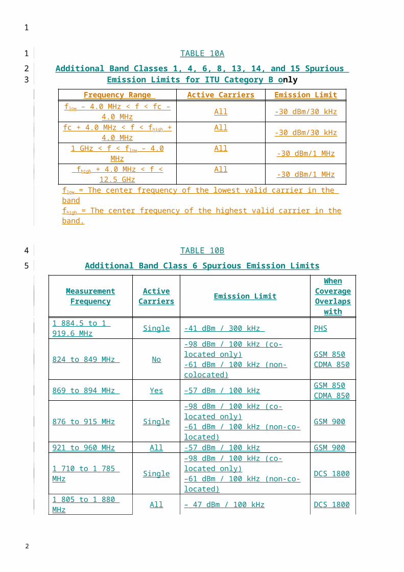
TABLE 22D
BS spurious emission limits for UTRA 7.68 Mchip/s option, Category B
Band Maximum level Measurement bandwidth
Notes
9 ↔ 150 kHz 36 dBm 1 kHz (1)
150 kHz ↔ 30 MHz 36 dBm 10 kHz (1)
30 MHz ↔ 1 GHz 36 dBm 100 kHz (1)
1 GHz ↔ FlowFc1 – 60 MHz or Fl – 10 MHz whichever is the higher
30 dBm 1 MHz (1)
Fc1 – 60 MHz or Fl – 10 MHz whichever is the higher ↔ Fc1 – 50 MHz or Fl – 10 MHz whichever is the higher
25 dBm 1 MHz (2)
FlowFc1 – 50 MHz or Fl – 10 MHz « Fhighwhichever is the higher ↔ Fc1 + 50 MHz or Fl + 10 MHz whichever is the lower
15 dBm 1 MHz (2)
Fc1 + 50 MHz or Fl + 10 MHz whichever is the lower ↔ Fc1 + 60 MHz or Fl + 10 MHz whichever is the lower
25 dBm 1 MHz (2)
FhighFc1 + 60 MHz or Fl + 10 MHz «whichever is the lower ↔ 12.75 GHz
30 dBm 1 MHz (1), (3)
(1) Bandwidth as in Recommendation ITU-R SM.329, § 4.1.(2) Specification in accordance with Recommendation ITU-R SM.329, § 4.3 and Annex 7.(3) Bandwidth as in ITU-R SM.329, §4.3 and Annex 7. Upper frequency as in Recommendation ITU-R SM.329,
§ 2.5, Table 1.Flow: The lowest downlink frequency of the operating band.Fhigh: The highest downlink frequency of the operating band.Fc1: Centre frequency of emission of the first carrier transmitted by the BS.Fc2: Centre frequency of emission of the last carrier transmitted by the BS.Fl: Lower frequency of the band in which TDD operates.Fu: Upper frequency of the band in which TDD operates.
TABLE 22E
BS spurious emission limits for E-UTRA, Category B
Band Maximum level Measurement bandwidth Note
9 « 150 kHz 36 dBm 1 kHz (1) 150 kHz « 30 MHz 36 dBm 10 kHz (1) 30 MHz « 1 GHz 36 dBm 100 kHz (1) 1 GHz « 12.75 GHz 30 dBm 1 MHz (2) (1) Bandwidth as in Recommendation ITU-R SM.329, § 4.1.
( 2 ) Bandwidth as in Recommendation ITU-R SM.329, § 4.1. Upper frequency as in Recommendation ITU-R SM.329, § 2.5 Table 1.
1
1
2
3
4
5
2

4.1 Coexistence with GSM 900
This requirement may be applied for the protection of GSM 900 MS and GSM 900 BTS receivers in geographic areas in which both GSM 900 and UTRA are deployed.
TABLE 23A
BS spurious emissions limits for UTRA BS in geographic coverage areaof GSM 900 MS and GSM 900 BTS receivers
Band Maximum level
Measurement bandwidth Note
876-915 MHz −61 dBm 100 kHz921-960 MHz −57 dBm 100 kHz
4.2 Coexistence with DCS 1800
This requirement may be applied for the protection of DCS 1800 MS and DCS 1800 BTS receivers in geographic areas in which both DCS 1800 and UTRA are deployed.
TABLE 23B
BS spurious emissions limits for UTRA BS in geographic coverage area of DCS 1800 MS and DCS 1800 BTS receivers
Band Maximum level
Measurement bandwidth Note
1 710-1 785 MHz −61 dBm 100 kHz1 805-1 880 MHz −47 dBm 100 kHz
4.3 Coexistence with UTRA-FDD
This requirement may be applied to geographic areas in which both UTRA-TDD and UTRA-FDD operating in bands specified in Table 23c are deployed.
For TDD base stations which use carrier frequencies within the band 2 010-2 025 MHz the requirements apply at all frequencies within the specified frequency bands in Table 23c6.16. For the 3.84 Mchip/s TDD option base stations which use a carrier frequency within the band 1 900-1 920 MHz, the requirement apply at frequencies within the specified frequency range which are more than 12.5 MHz above the last carrier used in the frequency band 1 900-1 920 MHz. For the 1.28 Mchip/s TDD option base stations which use carrier frequencies within the band 1 900-1 920 MHz, the requirement applies at frequencies within the specified frequency range which are more than 4 MHz above the last carrier used in the frequency band 1 900-1 920 MHz. For the 7.68 Mchip/s TDD option base stations which use a carrier frequency within the band 1 900-1 920 MHz, the requirement applies at frequencies within the specified frequency range which are more than 25 MHz above the last carrier used in the frequency band 1 900-1 920 MHz.
The power of any spurious emission should not exceed values reported in Table 23c.
1
1
23
4
56
7
89
10
1112
13
1415
1617181920212223242526
27
2

TABLE 23C
BS spurious emissions limits for UTRA BS in geographic coverage area of UTRA-FDD
BS class Band Maximum level
Measurement bandwidth Note
Wide area BS 1 920-1 980 MHz −43 dBm(1) 3.84 MHzWide area BS 2 110-2 170 MHz −52 dBm 1 MHzWide area BS 2 500-2 570 MHz −43 dBm(2) 3.84 MHzWide area BS 2 620-2 690 MHz −52 dBm 1 MHzWide area BS 815-850 MHz −43 dBm(3) 3.84 MHz Applicable in JapanWide area BS 860-895 MHz −52 dBm(3) 1 MHz Applicable in JapanWide area BS 1 427.9 MHz-1 452.9 MHz −43 dBm(4) 3.84 MHz Applicable in
JapanWide area BSWide area BS 1 475.9 MHz-1 500.9 MHz −52 dBm(4) 1 MHz Applicable in
JapanWide area BSWide area BS 1 749.9-1 784.9 MHz −43 dBm(3) 3.84 MHz Applicable in JapanWide area BS 1 844.9-1 879.9 MHz −52 dBm(3) 1 MHz Applicable in JapanLocal area BS 1 920-1 980 MHz −40 dBm(1) 3.84 MHzLocal area BS 2 110-2 170 MHz −52 dBm 1 MHzLocal area BS 2 500-2 570 MHz −40 dBm(2) 3.84 MHzLocal area BS 2 620-2 690 MHz −52 dBm 1 MHz(1) For the 3.84 Mchip/s TDD option base stations which use carrier frequencies within the band
1 900-1 920 MHz, the requirement should be measured RRC filtered mean power with the lowest centre frequency of measurement at 1 922.6 MHz or 15 MHz above the highest TDD carrier used, whichever is higher. For the 1.28 Mchip/s TDD option base stations which use carrier frequencies within the band 1 900-1 920 MHz, the requirement should be measured RRC filtered mean power with the lowest centre frequency of measurement at 1 922.6 MHz or 6.6 MHz above the highest TDD carrier used, whichever is higher. For the 7.68 Mchip/s TDD option base stations which use carrier frequencies within the band 1 900-1 920 MHz, the requirement should be measured RRC filtered mean power with the lowest centre frequency of measurement at 1 922.6 MHz or 30 MHz above the highest TDD carrier used, whichever is higher.
(2) For the 3.84 Mchip/s TDD option base stations which use carrier frequencies within the band 2 570-2 620 MHz, the requirement should be measured RRC filtered mean power with the highest centre frequency of measurement at 2 567.5 MHz or 15 MHz below the lowest TDD carrier used, whichever is lower. For the 1.28 Mchip/s TDD option base stations which use carrier frequencies within the band 2 570-2 620 MHz, the requirement should be measured RRC filtered mean power with the highest centre frequency of measurement at 2 567.5 MHz or 6.6 MHz below the lowest TDD carrier used, whichever is lower. For the 7.68 Mchip/s TDD option base stations which use carrier frequencies within the band 2 570-2 620 MHz, the requirement should be measured RRC filtered mean power with the highest centre frequency of measurement at 2 567.5 MHz or 30 MHz below the lowest TDD carrier used, whichever is lower.
(3) This is applicable only in Japan for the 3.84 Mchip/s and 7.68 Mchip/s TDD options operating in 2 010-2 025 MHz.
(4) This is applicable only to the 7.68 Mchip/s TDD option operating in 2 010-2 025 MHz.
The requirements for wide area BS in Table 23c are based on a coupling loss of 67 dB between the TDD and FDD base stations. The requirements for local area BS in Table 23c are based on a coupling loss of 70 dB between TDD and FDD wide area base stations.
1
1
2
345
2

4.4 Coexistence with PHS
This requirement may be applied for the protection of PHS in geographic areas in which both PHS and UTRA TDD or E-UTRA TDD are deployed. For the 3.84 Mchip/s TDD option, this requirement is also applicable at specified frequencies falling between 12.5 MHz below the first carrier frequency used and 12.5 MHz above the last carrier frequency used. For the 7.68 Mchip/s TDD option, this requirement is also applicable at specified frequencies falling between 25 MHz below the first carrier frequency used and 25 MHz above the last carrier frequency used. For E-UTRA TDD, this requirement is also applicable at specified frequencies falling between 10 MHz below the lowest BS transmitter frequency of the operating band and 10 MHz above the highest BS transmitter frequency of the operating band.
The power of any spurious emission should not exceed values reported in Table 23d.
TABLE 23D
BS spurious emissions limits for UTRA BS in geographic coverage area of PHS (3.84 Mchip/s and 7.68 Mchip/s TDD options) and E-UTRA BS in geographic
coverage area of PHS
Band Maximum level
Measurement bandwidth Note
1 884.5-1 919.6 MHz −41 dBm 300 kHz Applicable for transmission in 2 010-2 025 MHz
5 Receiver spurious emission
The requirements apply to all BS with separate receive and transmit antenna ports. The test should be performed when both transmitter and receiver are on with the transmitter port terminated.
For BS equipped with only a single antenna connector for both transmitter and receiver, the requirements of transmitter spurious emissions should apply to this port, and this test need not be performed.
The requirements in this subclause should apply to BS intended for general-purpose applications.
The power of any spurious emission should not exceed the values given in the Tables below.
For E-UTRA, in addition to the requirements in Table 24f, the power of any spurious emission should not exceed the levels specified for Co-existence with other systems in the same geographical area in Clause 4.4.
1
1
23456789
10
11
12
131415
16
1718
192021
22
23
242526
2

5.1 3.84 Mchip/s UTRA TDD option
TABLE 24A
Receiver spurious emission requirements
Band Maximum level
Measurement bandwidth Note
30 MHz-1 GHz −57 dBm 100 kHz
1 GHz-1.9 GHz,1.98 GHz-2.01 GHz and
2.025 GHz-2.5 GHz−47 dBm 1 MHz
With the exception of frequencies between 12.5 MHz below the first carrier frequency and 12.5 MHz above the last carrier frequency used by the BS
1.9 GHz-1.98 GHz,2.01 GHz-2.025 GHz and
2.5 GHz-2.62 GHz−78 dBm 3.84 MHz
With the exception of frequencies between 12.5 MHz below the first carrier frequency and 12.5 MHz above the last carrier frequency used by the BS
2.62 GHz-12.75 GHz −47 dBm 1 MHz
With the exception of frequencies between 12.5 MHz below the first carrier frequency and 12.5 MHz above the last carrier frequency used by the BS
TABLE 24B
Additional receiver spurious emission requirements
Band Maximum level
Measurement bandwidth Note
815 MHz-850 MHz1 749.9 MHz-1 784.9 MHz −78 dBm 3.84 MHz
Applicable in Japan.With the exception of frequencies between 12.5 MHz below the first carrier frequency and 12.5 MHz above the last carrier frequency used by the BS
5.2 1.28 Mchip/s UTRA TDD option
TABLE 24C
Receiver spurious emission requirements
Band Maximum level
Measurement bandwidth Note
30 MHz-1 GHz −57 dBm 100 kHz1 GHz-1.9 GHz,
1.98 GHz-2.01 GHz and 2.025 GHz-2.50 3 GHz
2.4-2.50 GHz
−47 dBm 1 MHz
With the exception of frequencies between 4 MHz below the first carrier frequency and 4 MHz above the last carrier frequency used by the BS
1.9 GHz-1.98 GHz,2.01 GHz-2.025 GHz
2.3 GHz to 2.4 GHz and 2.5 GHz-2.62 GHz
−83 dBm 1.28 MHz
With the exception of frequencies between 4 MHz below the first carrier frequency and 4 MHz above the last carrier frequency used by the BS
2.62 GHz-12.75 GHz −47 dBm 1 MHz
With the exception of frequencies between 4 MHz below the first carrier frequency and 4 MHz above the last carrier frequency used by the BS
1
1
2
3
4
5
6
7
8
2
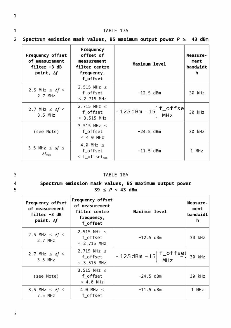
5.3 7.68 Mchip/s UTRA TDD option
TABLE 24D
Receiver spurious emission requirements
Band Maximum level
Measurement bandwidth Note
30 MHz-1 GHz −57 dBm 100 kHz
1 GHz-1.9 GHz,1.98 GHz-2.01 GHz2.025 GHz-2.5 GHz
−47 dBm 1 MHz
With the exception of frequencies between 25 MHz below the first carrier frequency and 25 MHz above the last carrier frequency used by the BS
1.9 GHz-1.98 GHz,2.01 GHz-2.025 GHz2.5 GHz-2.62 GHz
−75 dBm 7.68 MHz
With the exception of frequencies between 25 MHz below the first carrier frequency and 25 MHz above the last carrier frequency used by the BS
2.62 GHz-12.75 GHz −47 dBm 1 MHz
With the exception of frequencies between 25 MHz below the first carrier frequency and 25 MHz above the last carrier frequency used by the BS
TABLE 24E
Additional receiver spurious emission requirementsBand Maximum
levelMeasurement
bandwidth Note
815 MHz-850 MHz1 427.9 MHz-1 452.9 MHz1 749.9 MHz-1 784.9 MHz
−78 dBm 3.84 MHz
Applicable in Japan.With the exception of frequencies between 25 MHz below the first carrier frequency and 25 MHz above the last carrier frequency used by the BS
5.4 E-UTRA TDD option
TABLE 24F
Receiver spurious emission limits
Band Maximum level
Measurement bandwidth Note
30 MHz-1 GHz 57 dBm 100 kHz1-12.75 GHz 47 dBm 1 MHz
NOTE – For E-UTRA, the frequency range between 2.5 * BWChannel below the first carrier frequency and 2.5 * BWChannel above the last carrier frequency transmitted by the BS, where BWChannel is the channel bandwidth, may be excluded from the requirement. However, frequencies that are more than 10 MHz below the lowest frequency of the BS transmitter operating band or more than 10 MHz above the highest frequency of the BS transmitter operating band shall not be excluded from the requirement.
1
1
2
3
4
5
6
7
8
9
10
2
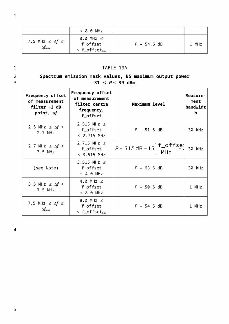
Annex 4
TDMA Single-Carrier (UWC-136) mobile stations
Part A
Conformance requirements (30 kHz)
1 Spectrum mask
Spectrum noise suppression is the restraint of sideband energy outside the active transmit channel. This RF spectrum is the result of power ramping, modulation and all sources of noise. The spectrum is primarily the result of events that do not occur at the same time: digital modulation and power ramping (switching transients). The RF spectrum from these two events are specified separately.
Adjacent and first or second alternate channel power is that part of the mean power output of the transmitter resulting from the modulation and noise which falls within a specified passband centred on either of the adjacent or first or second alternate channels.
The emission power should not exceed the limits specified in Table 19.
TABLE 19
Adjacent and alternate channel power requirements
OoB power arising from switching transients is the peak power of the spectrum, arising from the ramping-on and ramping-off of the transmitter, that fall within defined frequency bands outside the active transmit channel.
The peak emission power should not exceed the limits specified in Table 20.
Channel Maximum level
In either adjacent channel, centred 30 kHz from the centre frequency
26 dB below the mean output power
In either alternate channel, centred 60 kHz from the centre frequency
45 dB below the mean output power
In either second alternate channel centred 90 kHz from the centre frequency
45 dB below the mean output power or –13 dBm measured in 30 kHz bandwidth, whichever is the lower power
1
123
4
5
6
7
8
9101112
131415
16
17
18
192021
22
2
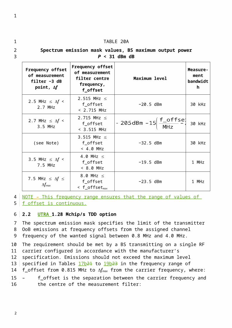
TABLE 20
Switching transients requirements
2 Transmitter spurious emissions (conducted)
The power of any spurious emission should not exceed the limits specified in Table 21.
TABLE 21
MS spurious emission limits
2.1 Coexistence with services in adjacent frequency bands
This requirement provides for the protection of receivers operating in bands adjacent to the MS transmit frequency band of 1 920 to 1 980 MHz: GSM 900, R-GSM and UTRA TDD.NOTE 1 – UTRA FDD operates in the same frequency band as UWC-136.
The power of any spurious emission should not exceed the limits specified in Table 22.
TABLE 22
Additional spurious emissions requirements
Channel Maximum level
In either adjacent channel, centred 30 kHz from the centre frequency
26 dB below the peak output power reference
In either alternate channel, centred 60 kHz from the centre frequency
45 dB below the peak output power reference
In either second alternate channel centred 90 kHz from the centre frequency
45 dB below the peak output power reference or –13 dBm measured in 30 kHz bandwidth, whichever is the lower power
Band ( f ) (1) Maximum level(dBm)
Measurement bandwidth Note
9 kHz f 150 kHz –36 1 kHz (2)
150 kHz f 30 MHz –36 10 kHz (2)
30 MHz f 1 000 MHz –36 100 kHz (2)
1 000 MHz f 1 920 MHz –30 1 MHz (2)
1 920 MHz f 1 980 MHz –30 30 kHz (3)
1 980 MHz f 2 110 MHz –30 1 MHz (2)
2 110 MHz f 2 170 MHz –70 30 kHz (4)
2 170 MHz f 12.75 GHz –30 1 MHz (2)
(1) f is the frequency of the spurious emission.(2) In accordance with the applicable clauses of Recommendation ITU-R SM.329.(3) MS transmit band.(4) MS receive band.
1
1
2
3
4
5
6
7
89
10
11
12
13
2

3 Receiver spurious emissions (idle mode)
The power of any spurious emissions should not exceed the limits given in Table 23.
TABLE 23
General receiver spurious emission requirements
Service Frequency bandMeasurement
bandwidth(kHz)
Limit(dBm)
R-GSM 921 f 925 MHz 100 –60R-GSM 925 f 935 MHz 100 –67
GSM 900/R-GSM 935 f 960 MHz 100 –79DCS 1800 1 805 f 1 880 MHz 100 –71
UTRA TDD 1 900 f 1 920 MHz 100 –62UTRA TDD 2 010 f 2 025 MHz 100 –62
NOTE 1 – The measurements are made on frequencies which are integer multiples of 200 kHz. Up to five exceptions of up to –36 dBm are permitted in the GSM 900, DCS 1800 and UTRA bands, and up to three exceptions of up to –36 dBm are permitted in the GSM 400 bands.
Frequency band Measurement bandwidth
Maximum level
(dBm)Note
30 MHz f 1 GHz 100 kHz –571 GHz f 12.75 GHz 1 MHz – 47 With the exception of the frequencies
covered by the table below, for which additional receiver spurious emission requirements apply(1)
(1) (Editorial Note) – In TFES Harmonized Standard v1.0.2, no additional receiver spurious emission is specified; yet, it is expected that there will be a table added, in the same form as for the other technologies (see Tables 5, 12 and 18).
1
1
2
3
4
2
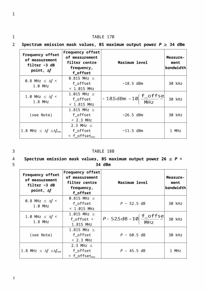
PART B
Conformance requirements (200 kHz)
The 200 kHz channel provides packet data service and employs both 8-level phase shift keying (8-PSK) and Gaussian minimum shift keying (GMSK) modulations.
1 Spectrum mask
Output RF spectrum is the relationship between the frequency offset from the carrier and the power, measured in a specified bandwidth and time, produced by the MS due to the effects of modulation and power ramping.
The specifications contained in this subclause apply in frequency hopping as well as in non-frequency hopping modes.
Due to the bursty nature of the signal, the output RF spectrum results from two effects: the modulation process, and the power ramping up and down (switching transients).– The level of the output RF spectrum due to GMSK and 8-PSK modulations should be no
more than that given in Tables 24 and 25.– The level of the output RF spectrum due to switching transients should be no more than that
given in Table 26.– The power emitted should not exceed –71 dBm in frequency band 2 110-2 170 MHz.
2 Spectrum due to the modulation and wideband noise
The output RF modulation spectrum is specified in Tables 24 and 25. This specification applies for all RF channels supported by the equipment.
The specification applies to the entire relevant transmit band and up to 2 MHz either side.
The limits should be met under the following measurement conditions:– Zero frequency scan, filter bandwidth and video bandwidth of 30 kHz up to 1 800 kHz from
the carrier and 100 kHz at 1 800 kHz and above from the carrier, with averaging done over 50% to 90% of the useful part of the transmitted bursts, excluding the midamble, and then averaged over at least 200 such burst measurements. Above 1 800 kHz from the carrier, only measurements centred on 200 kHz multiples are taken with averaging over 50 bursts.
– When tests are done in frequency hopping mode, the averaging should include only bursts transmitted when the hopping carrier corresponds to the nominal carrier of the measurement. The limits then apply to the measurement results for any of the hopping frequencies.
The figures in Table 24, at the vertically listed power level (dBm) and at the horizontally listed frequency offset from the carrier (kHz), are then the maximum allowed level (dB) relative to a measurement in 30 kHz on the carrier.NOTE 1 – This approach of specification has been chosen for convenience and speed of testing. It does however require careful interpretation if there is a need to convert figures in the following tables into spectral density values, in that only part of the power of the carrier is used as the relative reference, and in addition different measurement bandwidths are applied at different offsets from the carrier.
1
1
2
34
5
678
910
11121314151617
18
1920
21
22232425262728293031
32333435363738
2

TABLE 24
Relative maximum level due to modulation
The following exceptions should apply, using the same measurement conditions as specified above:– In the combined range of 600 kHz to 6 MHz above and below the carrier, in up to three
bands of 200 kHz width centred on a frequency which is an integer multiple of 200 kHz, exception levels of up to –36 dBm are allowed.
– Above 6 MHz offset from the carrier in up to 12 bands of 200 kHz width centred on a frequency which is an integer multiple of 200 kHz, exception levels of up to –36 dBm are allowed.
Using the same measurement conditions as specified above, if a requirement in Table 24 results in lower than the power limit given in Table 25, then the latter should be applied instead.
TABLE 25
Absolute maximum level due to modulation
3 Spectrum due to switching transients
These effects are also measured in the time domain and the specifications assume the following measurement conditions: zero frequency scan, filter bandwidth 30 kHz, peak hold, and video bandwidth 100 kHz. Table 26 specifies the limits.
Carrier power (dBm)
Frequency offset(kHz)
100 200 250 400 6001 200
1 2001 800
1 800
6 000
6 000
33 0.5 –30 –33 –60 –60 –60 –68 –7632 0.5 –30 –33 –60 –60 –60 –67 –7530 0.5 –30 –33 –60 –60(1) –60 –65 –7328 0.5 –30 –33 –60 –60(1) –60 –63 –7126 0.5 –30 –33 –60 –60(1) –60 –61 –69
24 0.5 –30 –33 –60 –60(1) –60 –59 –67(1) For equipment supporting 8-PSK, the requirement for 8-PSK modulation is –54 dB.
Frequency offset from the carrier(kHz)
Level(dBm)
600 –36 600, 1 800 –56
1 800 –51
1
1
2
3
456789
10
1112
13
14
15
161718
19
2
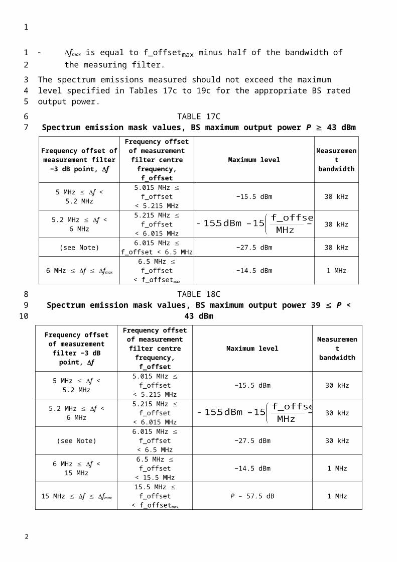
TABLE 26
Maximum levels due to switching transients
NOTE 1 – The relaxation for carrier power level 39 dBm is in line with the modulated spectra and thus causes negligible additional interference to an analogue system by an UWC-136 200 kHz signal.NOTE 2 – The near-far dynamics with this specification has been estimated to be approximately 58 dB for MS operating at a power level of 8 W or 49 dB for MSs operating at a power level of 1 W. The near-far dynamics then gradually decreases by 2 dB per power level down to 32 dB for MSs operating in cells with a maximum allowed output power of 20 mW or 29 dB for MS operating at 10 mW.NOTE 3 – The possible performance degradation due to switching transient leaking into the beginning or the end of a burst, was estimated and found to be acceptable with respect to the BER due to co-channel interference (C/I).
4 Transmitter spurious emissions (conducted)
The power of any spurious emission should not exceed the limits specified in Table 27.
TABLE 27
MS spurious emission limits
Carrier power level(dBm)
Maximum level measured at various frequency offsets
400 kHz 600 kHz 1 200 kHz 1 800 kHz39 –21 dBm –26 dBm –32 dBm –36 dBm
37 –23 dBm –26 dBm –32 dBm –36 dBm
Band ( f )(1) Measurement bandwidth
Maximum level(dBm) Note
9 kHz f 150 kHz 1 kHz –36 (2)
150 kHz f 30 MHz 10 kHz –36 (2)
30 MHz f 1 000 MHz 100 kHz –36 (2)
1 000 MHz f 1 920 MHz 1 MHz –30 (2)
1 920 MHz f 1 980 MHz 100 kHz –36 (3)
1 980 MHz f 2 110 MHz 1 MHz –30 (2)
2 110 MHz f 2 170 MHz 100 kHz –66 (4)
2 170 MHz f 12.75 GHz 1 MHz –30 (2)
(1) f is the frequency of the spurious emission.(2) In accordance with the applicable clauses of Recommendation ITU-R SM.329.(3) MS transmit band.(4) MS receive band.
1
1
2
456789
101112
13
14
15
16
18
2

5 Coexistence with services in adjacent frequency bands
This requirement provides for the protection of receivers operating in bands adjacent to the MS transmit frequency band of 1 920 MHz to 1 980 MHz: GSM 900, R-GSM, UTRA TDD.
The power of any spurious emission should not exceed the limits specified in Table 28.
TABLE 28
Additional spurious emissions requirements
6 Receiver spurious emissions (idle mode)
The power of any spurious emissions should not exceed the limits given in Table 29.
TABLE 29
General receiver spurious emission requirements
Service Frequency bandMeasurement
bandwidth(kHz)
Minimum requirement(dBm)
R-GSM 921 f 925 MHz 100 –60R-GSM 925 f 935 MHz 100 –67
GSM 900/R-GSM 935 f 960 MHz 100 –79DCS 1800 1 805 f 1 880 MHz 100 –71
UTRA TDD 1 900 f 1 920 MHz 100 –62UTRA TDD 2 010 f 2 025 MHz 100 –62
NOTE 1 – The measurements are made on frequencies which are integer multiples of 200 kHz. Up to five exceptions of up to –36 dBm are permitted in the GSM 900, DCS 1800 and UTRA bands, and up to three exceptions of up to –36 dBm are permitted in the GSM 400 bands.
Frequency bandMeasurement
bandwidthMaximum
level(dBm)
Note
30 MHz f 1 GHz 100 kHz –571 GHz f 12.75 GHz 1 MHz –47 With the exception of the frequencies
covered by the table below, for which additional receiver spurious emission requirements apply(1)
(1) (Editorial Note) – In TFES Harmonized Standard v1.0.2, no additional receiver spurious emission is specified; yet, it is expected that there will be a table added, in the same form as for the other technologies (see Tables 5, 12 and 18).
1
1
23
4
5
6
7
8
9
10
2
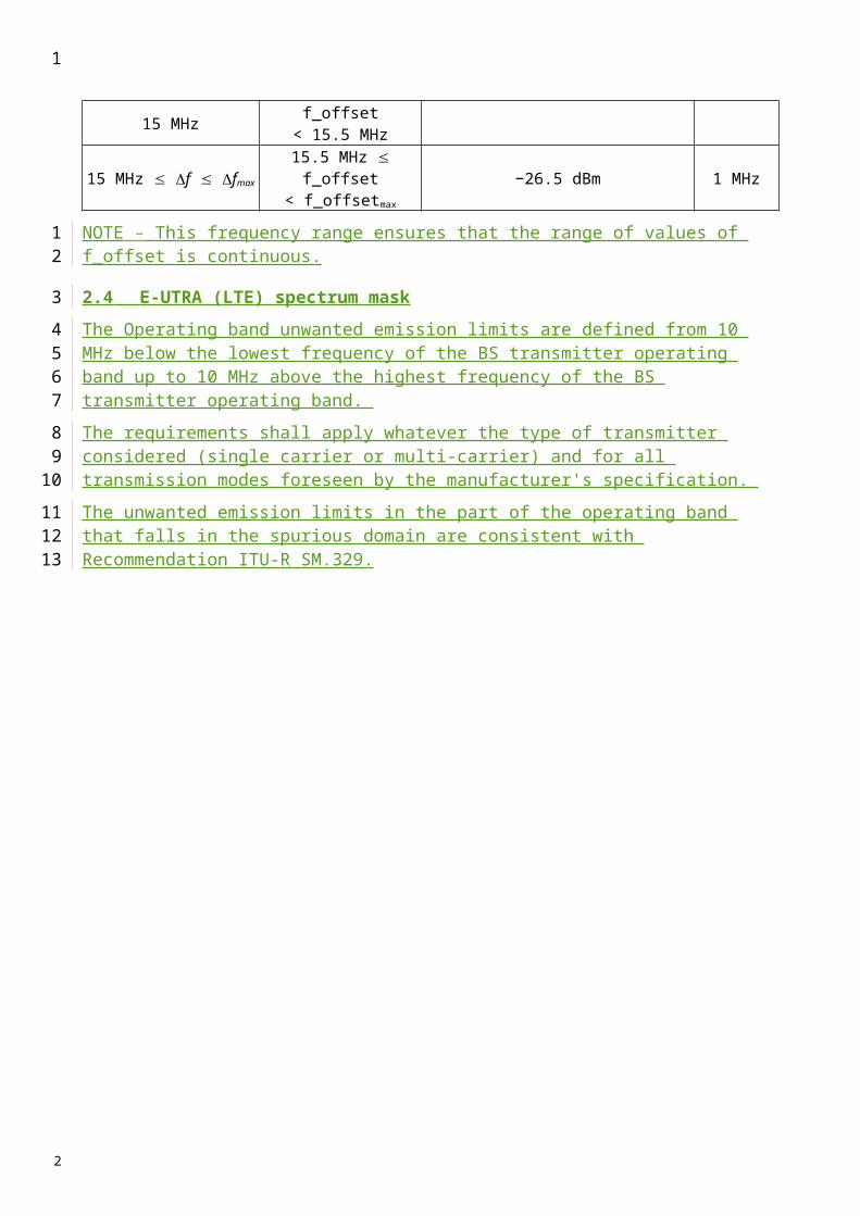
Annex 5
FDMA/TDMA (digital enhanced cordless telecommunications(DECT)) mobile stations
1 Spectrum mask
If the equipment under test (EUT) is equipped with antenna diversity, the EUT should have the diversity operation defeated for the following tests.
2 Emissions due to modulation
The unwanted emission(s) due to modulation is the power measured in any DECT RF channel other than the one in which the EUT is transmitting, integrated over a bandwidth of 1 MHz.
With transmissions on physical channel Ra (K, L, M, N) in successive frames, the power in physical channel Ra (K, L, Y, N) should be less than the values given in Table 30.
TABLE 30
Emissions modulation
3 Emissions due to transmitter transients
The power level of all modulation products (including AM components due to the switching on or off of the modulated RF carrier) in a DECT RF channel as a result of a transmission on another DECT RF channel.
The power level of all modulation products (including AM products due to the switching on or off of a modulated RF carrier) arising from a transmission on RF channel M should, when measured using a peak hold technique, be less than the values given in Table 31.
TABLE 31
Emissions due to transmitter transients
Emissions on RF channel “Y ” Measurement bandwidth Maximum power level
Y M 1 (1) 160 mW (–8 dBm)Y M 2 (1) 1 mW (–30 dBm)Y M 3 (1) 80 nW (–41 dBm)
Y any other DECT channel (1) 40 nW (–44 dBm)(2)
(1) The power in RF channel Y is defined by integration over a bandwidth of 1 MHz centred on the nominal centre frequency, FY, averaged over at least 60% but less than 80% of the physical packet, and starting before 25% of the physical packet has been transmitted but after the synchronization word.(2) For Y “any other DECT channel”, the maximum power level should be less than 40 nW (–44 dBm) except for one instance of a 500 nW (–33 dBm) signal.
1
1234
5
67
8
910
1112
13
14
15
161718
192021
22
23
2
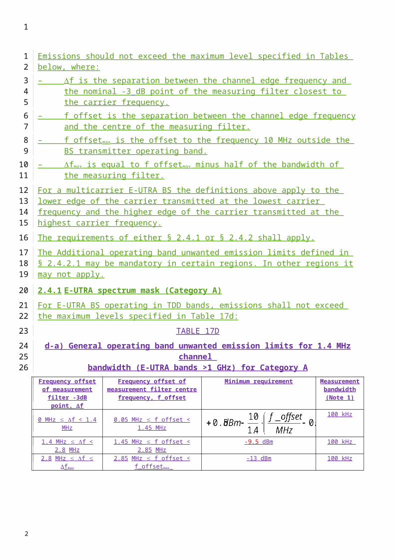
4 Transmitter spurious emissions (conducted)
4.1 Spurious emissions when allocated a transmit channel
The spurious emissions, when a radio end point has an allocated physical channel, should meet the requirements of Table 32. The requirements of Table 32 are only applicable for frequencies which are greater than 12.5 MHz away from the centre frequency, fc, of a carrier.
TABLE 32
Spurious emissions requirements
Measurements should not be made for transmissions on the RF channel closest to the nearest band edge for frequency offsets of up to 2 MHz.
5 Receiver spurious emissions (idle mode)
5.1 Spurious emissions when the EUT has no allocated transmit channel
The power level of any spurious emissions when the radio end point has no allocated transmit channel should not exceed the limits specified in Table 33.
TABLE 33
Receiver spurious emissions
Emissions on RF channel “Y ” Measurement bandwidth Maximum power level
Y M 1 (1) 250 mW (–6 dBm)Y M 2 (1) 40 mW (–14 dBm)Y M 3 (1) 4 mW (–24 dBm)
Y any other DECT channel (1) 1 mW (–30 dBm)(1) The measurement bandwidth should be 100 kHz and the power should be integrated over a 1 MHz bandwidth centred on the DECT frequency, FY.
Frequency Minimum requirement/ Reference bandwidth
30 MHz f 1 000 MHz –36 dBm/100 kHz1 GHz f 12.75 GHz –30 dBm/1 MHz
fc – 12.5 MHz f fc 12.5 MHz Not defined
1
1
2
345
6
7
89
10
11
1213
14
15
2
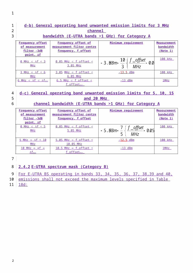
5.2 In the DECT band
The power level of any receiver spurious emissions within the DECT band should not exceed the limit in Table 34.
TABLE 34
Receiver spurious emissions within DECT band
Frequency band Measurement bandwidth
Maximum level
(dBm)Note
30 MHz f 1 GHz 100 kHz (1) –57
1 GHz f 12.75 GHz 1 MHz (1) –47 With the exception of the frequencies
within the DECT band, covered by Table 34
(1) The power should be measured using a peak hold technique.
Frequency band(MHz)
Measurement bandwidth
(MHz)
Maximum level(dBm)
1 900-1 920 2 010-2 025 1 –57(1)
(1) The following exceptions are allowed:
– in one 1 MHz band, the maximum allowable e.r.p. should be less than 20 nW;
– in up to two bands of 30 kHz, the maximum e.r.p. should be less than 250 nW.
1
1
23
4
5
2
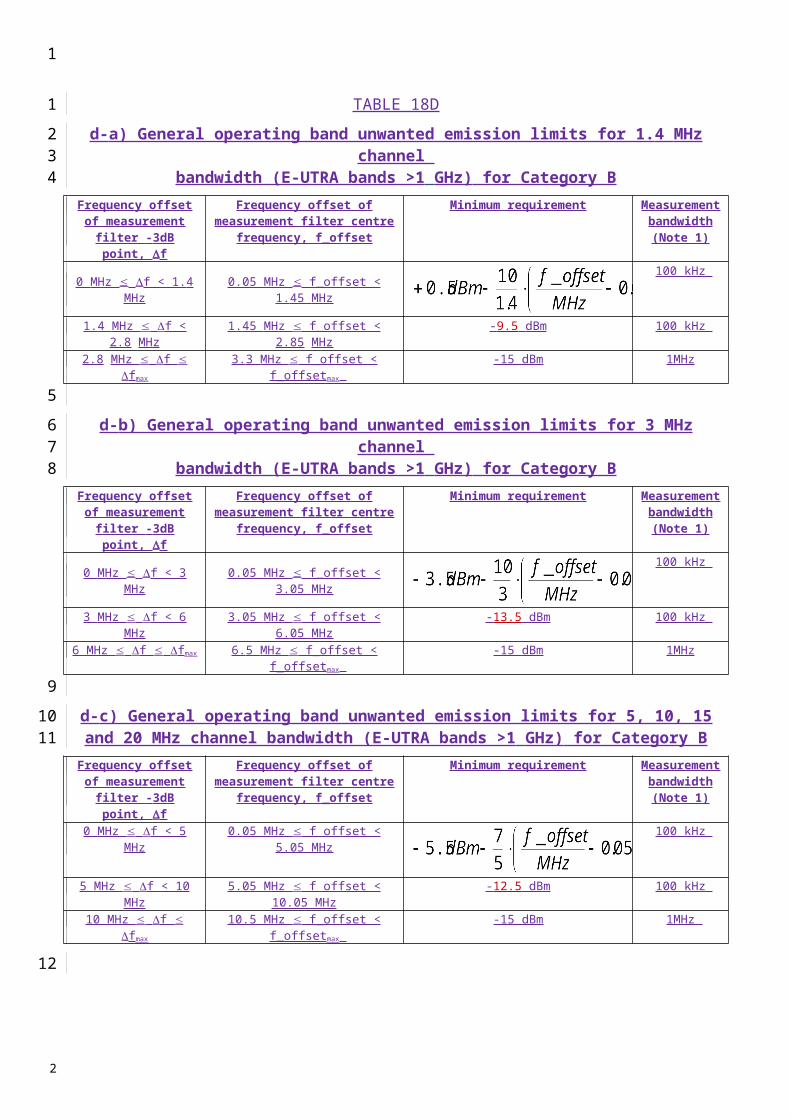
Annex 6
IMT-2000 OFDMA TDD WMAN base stations
1 Introduction
This Annex identifies unwanted emission limits for IMT-2000 OFDMA TDD WMAN base stations.
2 Spectrum emission mask
2.1 Spectrum emission mask for equipment operating in the band 2 300-2 400 MHz
TBD
2.2 Spectrum emission mask for equipment operating in the band 2 500-2 690 MHz
The spectrum emission mask of base stations applies to frequency offsets between 2.5 MHz and 12.5 MHz away from the base station centre frequency for the 5 MHz carrier and between 5 MHz and 25 MHz away from the base station centre frequency for the 10 MHz carrier. f is defined as the frequency offset in MHz from the channel centre frequency.
TABLE 47
Spectrum emission mask for 5 MHz carrier – generic
Frequency offset from centre
Allowed emission level
Measurement bandwidth
2.5 f 3.5 MHz 13 dBm 50 kHz3.5 f < 12.5 MHz 13 dBm 1 MHz
TABLE 48
Spectrum emission mask for 10 MHz carrier – generic
Frequency offset from centre
Allowed emission level
Measurement bandwidth
5 f 6 MHz 13 dBm 100 kHz6 f < 25 MHz 13 dBm 1 MHz
1
123
4
56
7
8
9
10
11121314
15
16
17
18
19
2

TABLE 49
Adjacent channel leakage power – Japan
Channel size Measurement frequency range
(MHz)
Allowed adjacent channel leakage power
(dBm)
5 MHz 2.6 < f < 7.4 710 MHz 5.25 < f < 14.75 3
TABLE 50
Spectrum emission mask for 5 MHz carrier – Japan
Frequency offset from centre
Allowed emission level Measurement bandwidth
7.5 MHz f < 12.25 151.4 × (f 7.5) dBm 1 MHz12.25 f < 22.5 MHz 22 dBm 1 MHz
NOTE – The adjacent channel leakage power for the 5 MHz channel from 2.6 MHz to 7.4 MHz is shown in Table 49.
TABLE 51
Spectrum emission mask for 10 MHz carrier – Japan
Frequency offset from centre
Allowed emission level Measurement bandwidth
15 f < 25 MHz 22 dBm 1 MHzNOTE – The adjacent channel leakage power for the 10 MHz channel from 5.25 MHz to 14.75 MHz is shown in Table 49.
2.3 Spectrum emission mask for equipment operating in the band 3 400-3 600 MHz
TBD
3 Transmitter spurious emissions (conducted)
3.1 Transmitter spurious emissions
IMT-2000 OFDMA TDD WMAN base stations comply with the limits recommended in Recommendation ITU-R SM.329-10. The limits shown in Tables 52 and 53 are only applicable for frequency offsets which are greater than 12.5 MHz away from the base station centre frequency for the 5 MHz carrier and greater than 25 MHz for the 10 MHz carrier. f is the frequency of the spurious domain emissions. fc is the base station centre frequency.
The emission levels in Table 52 should be met in areas where Category A limits for spurious emissions, as defined in Recommendation ITU-R SM.329-10, are applicable. The emission levels in Table 53 should be met in areas where Category B limits for spurious emissions, as defined in Recommendation ITU-R SM.329-10, are applicable.
1
1
2
3
4
5
6
7
8
9
10
1112131415
16171819
2

TABLE 52
Base station spurious emission limit, Category A
Band Allowed emission
level
Measurement bandwidth
Note
30 MHz-1 GHz 13 dBm 100 kHz Bandwidth as in Recommendation ITU-R SM.329-10, § 4.1
1 GHz-13.45 GHz 1 MHz Upper frequency as in Recommendation ITU-R SM.329-10, § 2.5, Table 1
TABLE 53
Base station spurious emissions limit, Category B
Band Measurement bandwidth Allowed emission level
30 MHz f < 1 000 MHz 100 kHz –36 dBm
1 GHz f < 13.45 GHz30 kHz If 2.5 × BW <= | fc − f | < 10 × BW300 kHz If 10 × BW <= | fc − f | < 12 × BW1 MHz If 12 × BW <= | fc − f |
–30 dBm
TABLE 54
Base station spurious emission limit, Japan
Frequency bandwidth Measurement bandwidth
Allowed emission level(dBm)
9 kHz f < 150 kHz 1 kHz −13150 kHz f < 30 MHz 10 kHz −1330 MHz f < 1 000 MHz 100 kHz −131 000 MHz f < 2 505 MHz 1 MHz −132 505 MHz f < 2 535 MHz 1 MHz −422 535 MHz f < 2 630 MHz 1 MHz −13(1)2 630 MHz f < 2 634.75 MHz 1 MHz −15 − 7/5 × (f −2 629.75)2 634.75 MHz f < 2 655 MHz 1 MHz −222 655 MHz f 1 MHz −13(1) The allowed emission level for the frequency band between 2 535 MHz and 2 630 MHz shall be applied for the frequency range greater than 2.5 times the channel size from the centre frequency.
1
1
2
3
4
5
6
7
8
2
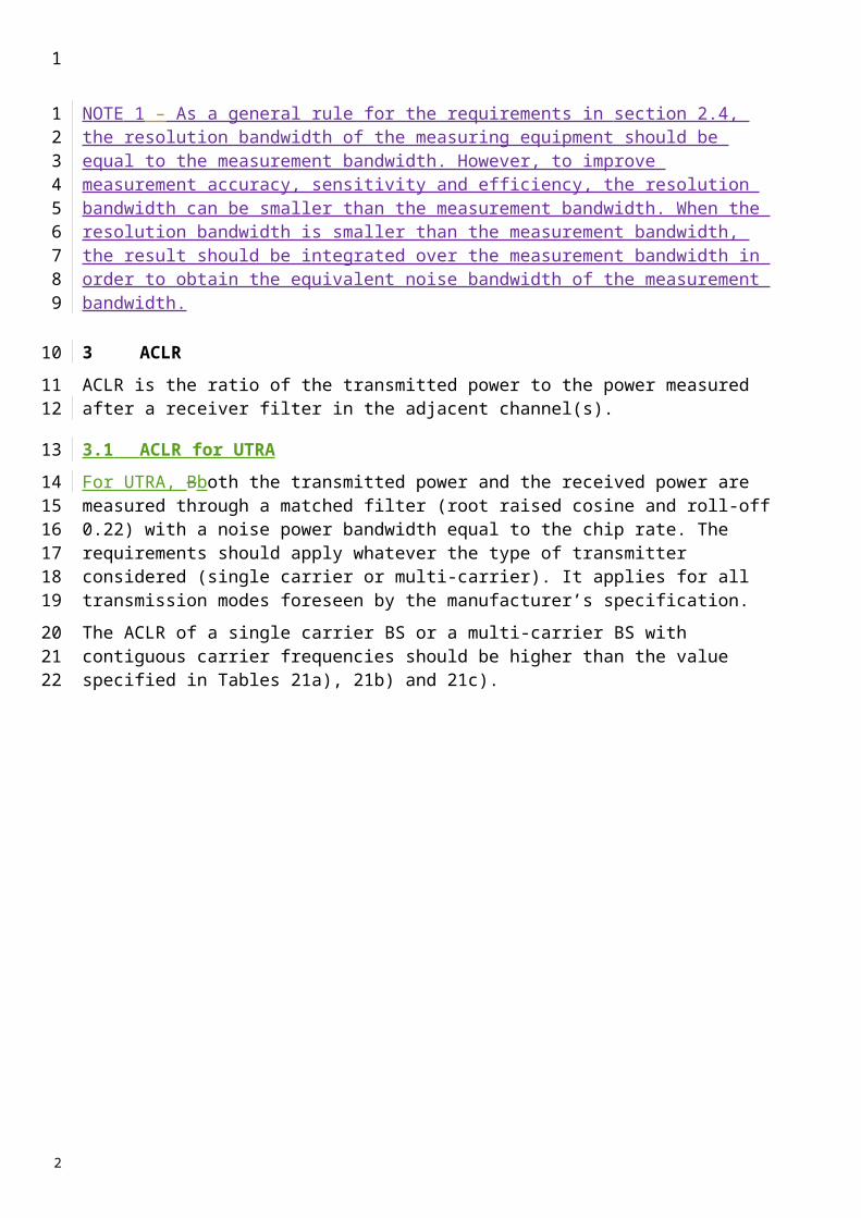
3.2 Coexistence with other systems in the same geographical/service area
These requirements may be applied for the protection of UE, MS and/or BS operating in other frequency bands in the same geographical area. The requirements may apply in geographical/service areas as applicable in which both OFDMA-TDD-WMAN and a system operating in another frequency band than the OFDMA-TDD-WMAN operating band are deployed. The systems operating in the other frequency band may be GSM900, DCS1800, PCS1900, GSM850, PHS, UTRA-TDD (3.84 Mchip/s, 7.68 Mchip/s, 1.28 Mchip/s options) and UTRA-FDD.
The power of any spurious emission should not exceed the limits of Table 57 for a BS where requirements for coexistence with the system listed in the first column apply.
TABLE 55
BS spurious emission limits for OFDMA-TDD-WMAN BS in geographic coverage area of systems operating in other frequency bands
System type operating in
the same geographical
area
Band for coexistence requirement
Maximum level
Measurement bandwidth
Note
GSM900921-960 MHz −57 dBm 100 kHz
876-915 MHz −61 dBm 100 kHz
DCS18001 805-1 880 MHz −47 dBm 100 kHz
1 710-1 785 MHz −61 dBm 100 kHz
PCS19001 930-1 990 MHz −47 dBm 100 kHz
1 850-1 910 MHz −61 dBm 100 kHz
GSM850869-894 MHz −57 dBm 100 kHz
824-849 MHz −61 dBm 100 kHz
PHS 1 884.5-1 919.6 MHz 41 dBm 300 kHz
FDD Band I2 110-2 170 MHz −52 dBm 1 MHz
1 920-1 980 MHz −49 dBm 1 MHz
FDD Band II1 930-1 990 MHz −52 dBm 1 MHz
1 850-1 910 MHz −49 dBm 1 MHz
FDD Band III1 805-1 880 MHz −52 dBm 1 MHz
1 710-1 785 MHz −49 dBm 1 MHz
FDD Band IV2 110-2 155 MHz −52 dBm 1 MHz
1 710-1 755 MHz −49 dBm 1 MHz
FDD Band V869-894 MHz −52 dBm 1 MHz
824-849 MHz −49 dBm 1 MHz
1
1
234567
89
10
1112
2
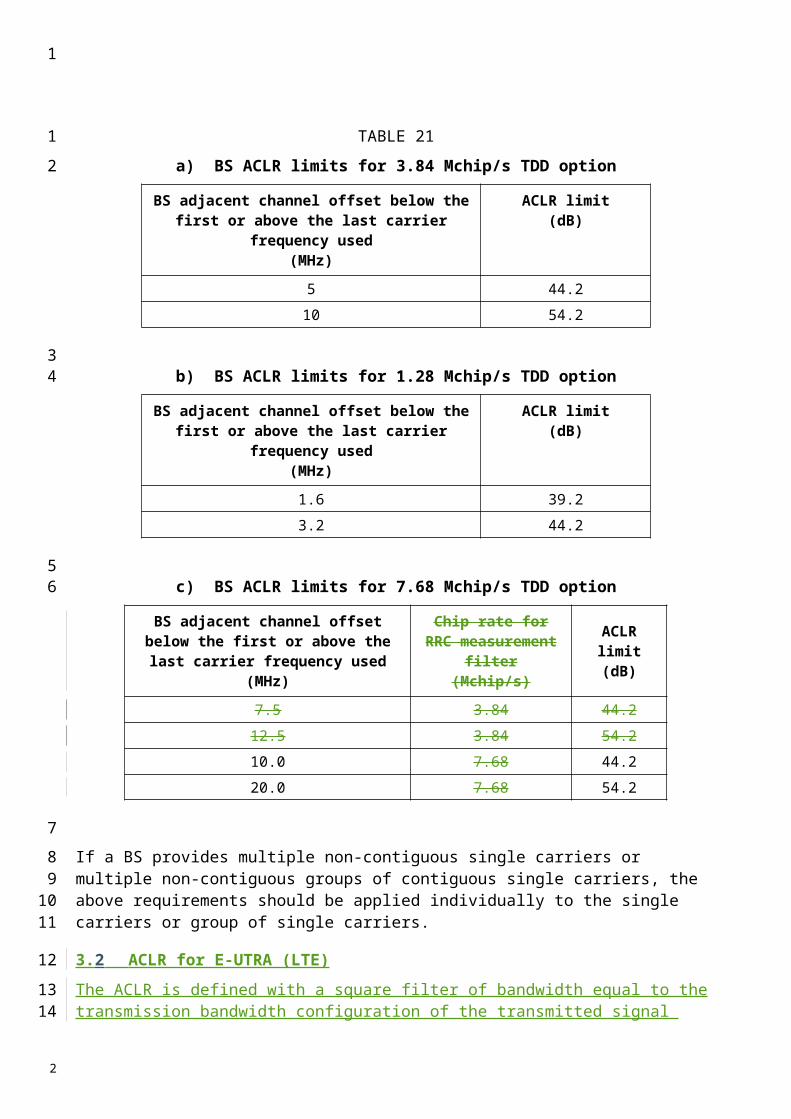
System type operating in
the same geographical
area
Band for coexistence requirement
Maximum level
Measurement bandwidth
Note
FDD Band VI860-895 MHz −52 dBm 1 MHz
815-850 MHz −49 dBm 1 MHz
FDD Band VII
2 620-2 690 MHz −52 dBm 1 MHzThis requirement does not apply to IP-OFDMA TDD WMAN operating in Band VII
2 500-2 570 MHz −49 dBm 1 MHzThis requirement does not apply to IP-OFDMA TDD WMAN operating in Band VII
FDD Band VIII925-960 MHz −52 dBm 1 MHz
880-915 MHz −49 dBm 1 MHz
FDD Band IX1 844.9-1 879.9 MHz −52 dBm 1 MHz1 749.9-1 784.9 MHz −49 dBm 1 MHz
FDD Band X2 110-2 170 MHz −52 dBm 1 MHz1 710-1 770 MHz −49 dBm 1 MHz
UTRA-TDD
1 900-1 920 MHz 52 dBm 1 MHz
2 010-2 025 MHz 52 dBm 1 MHz
2 300-2 400 MHz 52 dBm 1 MHz
This requirement does not apply to OFDMA TDD WMAN operating in the band 2 300-2 400 MHz
2 570-2 610 MHz 52 dBm 1 MHz
This requirement does not apply to OFDMA TDD WMAN operating in the band 2 500-2 690 MHz
NOTE 1 – The values in this table are considered as preliminary values only, and are subject to further study that could lead to a revision of this Recommendation.
4 Receiver spurious emissions (conducted)
The receiver spurious emissions in Table 56 are applied in Japan.
1
1
2
3
2

TABLE 56
Receiver spurious emission requirements
Frequency band Total allowed emission level(dBm)
f < 1 GHz –541 GHz f –47
5 Adjacent channel leakage ratio (ACLR)
5.1 ACLR values for equipment operating in the band 2 300-2 400 MHz
TBD
5.2 ACLR values for equipment operating in the band 2 500-2 690 MHz
Within this Annex, and in a similar manner to other annexes, the ACLR is defined as the ratio of the on-channel transmitted power to the power transmitted in adjacent channels as measured at the output of the receiver filter. In order to measure ACLR it is necessary to consider a measurement filter for the transmitted signal as well as a receiver measurement bandwidth for the adjacent channel (victim) system.
5.1 Inter-system and intra-system scenarios
There are two specific coexistence requirements that must be considered; the intra-system and inter-system. In this section only the following scenarios are considered:– OFDMA TDD WMAN adjacent to OFDMA TDD WMAN within the same network;– OFDMA TDD WMAN adjacent to UTRA technologies, which might operate using FDD or
unsynchronized TDD techniques. The ACLR in this case also takes into account the boundary coexistence conditions between an OFDMA TDD WMAN system and a UTRA system, which could happen in the case of deployments in adjacently assigned spectrum blocks.
In this text, only one inter-system scenario is discussed, that pertaining to UTRA. Two classes of ACLR figures are defined in this Annex to describe the two relevant scenarios as follows:
Intra-system scenario: A classification that identifies a level of minimum required ACLR performance generally appropriate for intra-system operation in contiguous channel assignments within the same network, i.e. OFDMA TDD WMAN adjacent to OFDMA TDD WMAN. In this Annex, intra-system ACLR is based on the following receiver bandwidths with the OFDMA TDD WMAN system operated on-channel and adjacent channel:– 4.75 MHz for a 5 MHz channelized system, and– 9.5 MHz for a 10 MHz channelized system.
UTRA scenario: A classification that identifies a level of minimum required ACLR performance appropriate for more demanding interoperator/coexistence scenarios at adjacent frequency block boundaries.
The following receiver bandwidths are assumed for the UTRA system:– 3.84 MHz for a 5 MHz channelized system, and
1
1
2
3
4
5
6
789
1011
12
1314151617181920
2122
23242526272829
303132
3334
2

– 7.68 MHz for a 10 MHz channelized system.
In each scenario, the passband of the receiver filter is centred on the first or second adjacent channel centre frequency. In the case where the adjacent system is OFDMA TDD WAN, both the transmitted power and the received power are measured with a rectangular filter. For adjacent UTRA systems the transmitted power is measured using a rectangular filter and the received power using a RRC filter with a roll-off factor of 0.22.
The ACLR values for the two relevant scenarios are provided in the following tables.
TABLE 57
a) BS ACLR for 5 MHz channel bandwidth – intra-system scenario
Adjacent channel centre frequency Minimum required ACLR(dB)
BS channel centre frequency ± 5 MHz 45BS channel centre frequency ± 10 MHz 55
b) BS ACLR for 5 MHz channel bandwidth – UTRA scenario
Adjacent channel centre frequency Minimum required ACLR(dB)
BS channel centre frequency ± 5 MHz 53.5BS channel centre frequency ± 10 MHz 66
c) BS ACLR for 10 MHz channel bandwidth – intra-system scenario
Adjacent channel centre frequency Minimum required ACLR(dB)
BS channel centre frequency ± 10.0 MHz 45BS channel centre frequency ± 20.0 MHz 55
d) BS ACLR for 10 MHz channel bandwidth –UTRA scenario
Adjacent channel centre frequency Minimum required ACLR(dB)
BS channel centre frequency ± 10.0 MHz 53.5BS channel centre frequency ± 20.0 MHz 66
Additional information may be provided in future revisions of this Recommendation.
NOTE 1 – Further study is necessary for other systems wherever applicable, as well as the relationship between ACLR and the emission mask.
1
1
23456
7
8
9
1011
1213
1415
16
17
1819
2
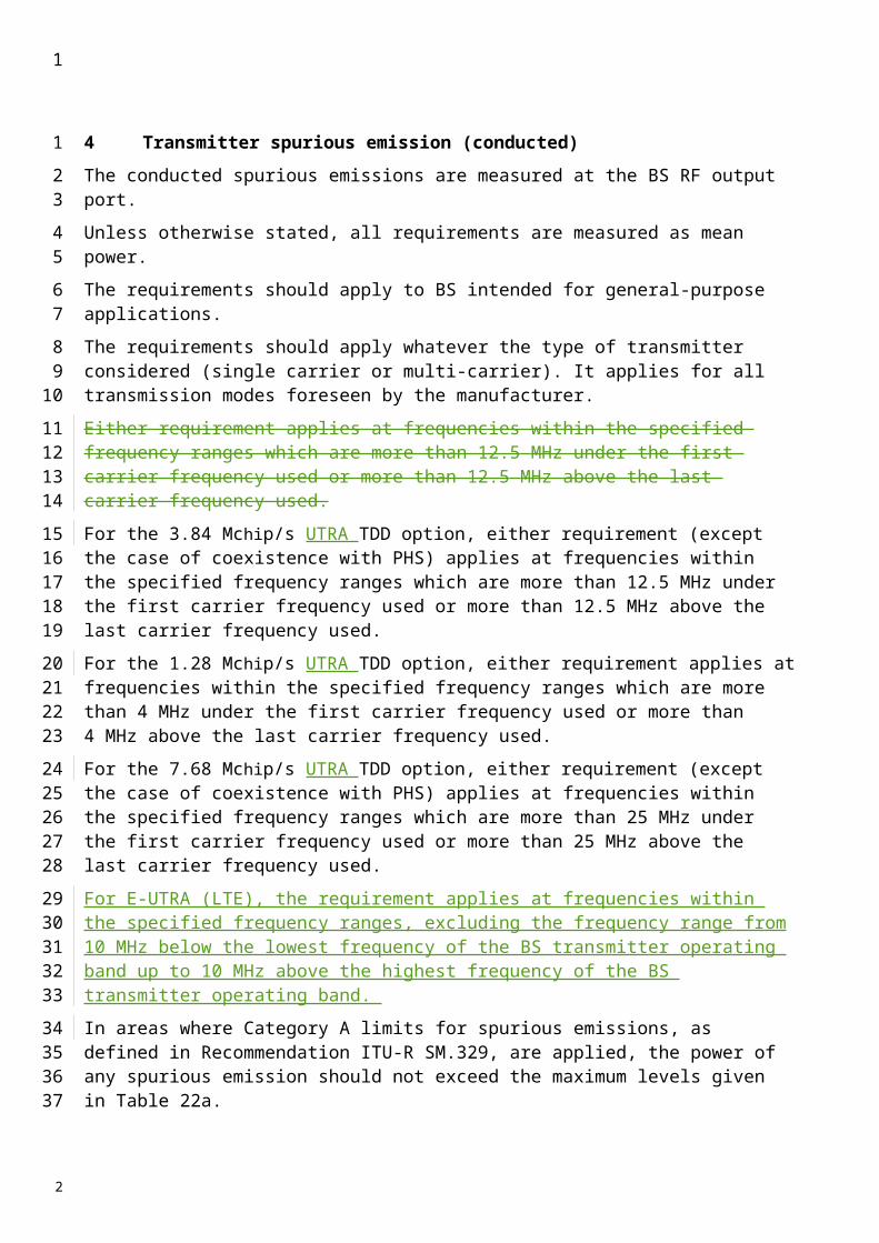
5.3 ACLR of equipment operating in the frequency range 3 400-3 600 MHz
TBD
1
1
2
2

Appendix 1
Definitions and Abbreviations
Test tolerance
With reference to Recommendation ITU-R M.1545, “test tolerance” is the relaxation value referred to in recommends 2 of ITU-R M.1545, i.e. the difference between the core specification value and the test limit, evaluated applying the shared risk principle as per figures 2 and 3 of annex 1 of ITU-R M.1545. In case the core specification value is equal to the test limit (figure 3 of annex 1 of ITU-R M.1545) the “test tolerances” are equal to 0.
1
123
4
5
6789
10
11
2

- 77 -
Source: Revision 1 to Document 5D/TEMP/129
Attachment 2
WORKING DOCUMENT TOWARDS THEA DRAFT REVISED REVISION OF RECOMMENDATION ITU-R M.1581-2*
Generic unwanted emission characteristics of mobile stations using the terrestrial radio interfaces of IMT-2000
(QUESTION ITU-R 229/8)(2002-2003-2007)
Scope
This Recommendation provides the generic unwanted emission characteristics of mobile stations using the terrestrial radio interfaces of IMT-2000, suitable for establishing the technical basis for global circulation of IMT-2000 terminals.”.
The ITU Radiocommunication Assembly,
considering
a) that unwanted emissions consist of both spurious and out-of-band (OoB) emissions according to No. 1.146 of the Radio Regulations (RR) and that spurious and OoB emissions are defined in RR Nos. 1.145 and 1.144, respectively;
b) that limitation of the maximum permitted levels of unwanted emissions of IMT-2000 mobile stations (MSs) is necessary to protect other radio systems and services from interference and to enable coexistence between different technologies;
c) that too stringent limits may lead to an increase in size or in complexity of IMT-2000 radio equipment;
d) that every effort should be made to keep limits for unwanted emissions at the lowest possible values taking account of economic factors and technological limitations;
e) that Recommendation ITU-R SM.329 relates to the effects, measurements and limits to be applied to spurious domain emissions;
f) that the same spurious emission limits apply equally to MSs of all radio interfaces;
g) that Recommendation ITU-R SM.1541 relating to OoB emission specifies generic limits in the OoB domain which generally constitute the least restrictive OoB emission limits and encourages the development of more specific limits for each system;
* This Recommendation should be brought to the attention of Radiocommunication Study Group 1.
1
1
2
3
456
7
8
91011
121314
1516
1718
1920
21
222324
3
4

h) that the levels of spurious emissions of IMT-2000 terminals shall comply with the limits specified in RR Appendix 3;
j) that Recommendation ITU-R M.15794 establishes the technical basis for global circulation of IMT-2000 MSs;
k) that one of the basic requirements of global circulation is that the MS does not cause harmful interference in any country where it is taken;
l) that the harmonization of unwanted emission limits will facilitate global use and access to a global market;
m) that additional work is needed in order to define unwanted emission limits for equipment operating in the bands identified for IMT-2000 at the World Radiocommunication Conference (Istanbul, 2000) (WRC-2000);
n) that unwanted emission limits are dependent on the transmitter emission characteristics in addition to depending on services operating in other bands,
noting
a) the work carried out by standardization bodies to define limits to protect other radio systems and services from interference and to enable coexistence between different technologies;
b) that IMT-2000 mobile stations must comply with local, regional, and international regulations for out-of-band and spurious emissions relevant to their operations, wherever such regulations apply;
c) with regard to Annex 6, IMT-2000 OFDMA TDD WMAN, additional urgent work, in particular on emission mask and ACLR, is needed to ensure geographical coexistence with other IMT-2000 radio interfaces,
recommends
1 that the unwanted emission characteristics of IMT-2000 MSs should be based on the limits contained in the technology specific Annexes 1 to 6 which correspond to the radio interface specifications described in § 5.1 to 5.6 of Recommendation ITU-R M.1457.
NOTE 1 – Except the cases stated in Note 2, Note 3, Note 4 and Note 54, the unwanted emission limits are only defined for mobile stations operating according to the following arrangement: frequency division duplex (FDD) uplink in the band 1 920-1 980 MHz, FDD downlink in the band 2 110-2 170 MHz and time division duplex (TDD) in the bands 1 885-1 980 and 2 010-2 025 MHz. Future versions of this Recommendation will include limits applicable to other frequency bands. Subject to further study, it is anticipated that such limits would be similar to those already contained in this Recommendation.
NOTE 2 – The unwanted emission limits defined in Annex 1 are for MS operating one of or a combination of the following arrangements:– Frequency division duplex (FDD) uplink in the band 1 920-1 980 MHz, FDD downlink in
the band 2 110-2 170 MHz, in Annex 1 referred to as FDD Band I in UTRA or Band 1 in E-UTRA.
– FDD uplink in the band 1 850-1 910 MHz, FDD downlink in the band 1 930-1 990 MHz, in Annex 1 referred to as FDD Band II in UTRA or Band 2 in E-UTRA.
– FDD uplink in the band 1 710-1 785 MHz, FDD downlink in the band 1 805-1 880 MHz, in Annex 1 referred to as FDD Band III in UTRA or Band 3 in E-UTRA.
1
12
34
56
78
91011
1213
14
1516
171819
202122
23
242526
27282930313233
343536373839404142
2

– FDD uplink in the band 1 710-1 755 MHz, FDD downlink in the band 2 110-2 155 MHz, in Annex 1 referred to as FDD Band IV in UTRA or Band 4 in E-UTRA.
– FDD uplink in the band 824-849 MHz, FDD downlink in the band 869-894 MHz, in Annex 1 referred to as FDD Band V in UTRA or Band 5 in E-UTRA.
– FDD uplink in the band 830-840 MHz, FDD downlink in the band 875-885 MHz, in Annex 1 referred to as FDD Band VI in UTRA or Band 6 in E-UTRA.
– FDD uplink in the band 2 500-2 570 MHz, FDD downlink in the band 2 620-2 690 MHz, in Annex 1 referred to as FDD Band VII in UTRA or Band 7 in E-UTRA.
– FDD uplink in the band 880-915 MHz, FDD downlink in the band 925-960 MHz, in Annex 1 referred to as FDD Band VIII in UTRA or Band 8 in E-UTRA.
– FDD uplink in the band 1 749.9-1 784.9 MHz, FDD downlink in the band 1 844.9-1 879.9 MHz, in Annex 1 referred to as FDD Band IX in UTRA or Band 9 in E-UTRA.
– FDD uplink in the band 1 710-1 770 MHz, FDD downlink in the band 2 110-2 170 MHz, in Annex 1 referred to as FDD Band X in UTRA or Band 10 in E-UTRA.
– FDD uplink in the band 1 427.9-1 452.9 MHz, FDD downlink in the band 1 475.9-1 500.9 MHz, in Annex 1 referred to as FDD Band XI in UTRA or Band 11 in E-UTRA.
– FDD uplink in the band 698-716 MHz, FDD downlink in the band 728-746 MHz, in Annex 1 referred to as FDD Band XII in UTRA.
– FDD uplink in the band 777-787 MHz, FDD downlink in the band 746-756 MHz, in Annex 1 referred to as FDD Band XIII in UTRA or Band 13 in E-UTRA.
– FDD uplink in the band 788-798 MHz, FDD downlink in the band 758-768 MHz, in Annex 1 referred to as FDD Band XIV in UTRA or Band 14 in E-UTRA.
Future versions of this Recommendation will include limits applicable to other frequency bands. Subject to further study, it is anticipated that such limits would be similar to those already contained in this Recommendation.
NOTE 3 – The unwanted emission limits defined in Annex 2 are for MS operating in the following arrangements and apply to both cdma2000 and HRPD operating modes except as noted:
1
123456789
101112131415161718192021222324
252627
2829
2

Band Class Name
MS Transmit Frequency
(MHz)
BS Transmit Frequency
(MHz)Band Group
0 800 MHz band 824-849 869-894 8001 1 900 MHz band 1 850-1 910 1 930-1 990 1 9002 TACS band 872-915 917-960 8003 JTACS band 887-925 832-870 8004 Korean PCS band 1 750-1 780 1 840-1 870 1 9005 450 MHz band 411-484 421-494 4506 2 GHz band 1 920-1 980 2 110-2 170 1 9007 700 MHz band 776-794 746-764 8008 1 800 MHz band 1 710-1 785 1 805-1 880 1 9009 900 MHz band 880-915 925-960 80010 Secondary 800 MHz band 806-901 851-940 80011 400 MHz European PAMR band 411-484 421-494 45012 800 MHz PAMR band 870-876 915-921 80013 2.5 GHz IMT-2000 extension band 2 500-2 570 2 620-2 690 N/A14 US PCS 1.9 GHz band 1 850-1 915 1 930-1 995 1 90015 AWS band 1 710-1 755 2 110-2 155 1 900
16* US 2.5 GHz band 2 502-2 568 2 624-2 690 N/A
* No emissions specifications at this time.
NOTE 34 – The unwanted emission limits defined in Annex 3 are for MS operating one of, or a combination of, the following arrangements:– Time division duplex (TDD) in the band 1 900-1 920 MHz and 2 010-2 025 MHz referred to
as Band b) in UTRA or Band 33 and 34, respectively, in E-UTRA. – TDD in the band 1 850-1 910 MHz and 1930-1990 MHz refered to as Band .b) in UTRA or
Band 35 and 36, respectively, in E-UTRA.– TDD in the band 1 910-1 930 MHz refered to as Band c) in UTRA or Band 37 in E-UTRA
TDD.– TDD in the band 2 570-2 620 MHz refered to as Band d) in UTRA or Band 38 in E-UTRA
TDD.– TDD in the band 1880-1920MHz refered to as Band 39 in E-UTRA. – TDD in the band 2300-2400MHz refered to as Band e) in UTRA or Band 40 in E-UTRA.
Future versions of this Recommendation will include limits applicable to other frequency bands. Subject to further study, it is anticipated that such limits would be similar to those already contained in this Recommendation.
NOTE 54 – The out-of-band emission limits defined in Annex 6 are for MS operating in the following arrangement:
1
1
2
3456789
101112131415
161718
1920
2

– TDD in the band 2 300-2 400 MHz;
– TDD in the band 2 500-2 690 MHz;
– TDD in the band 3 400-3 600 MHz.
Annex 1: IMT-2000 Code division multiple access (CDMA) Direct Spread mobile stations
Annex 2: IMT-2000 CDMA Multi-Carrier mobile stations
Annex 3: IMT-2000 CDMA TDD mobile stations
Annex 4: IMT-2000 TDMA Single-Carrier mobile stations
Annex 5: IMT-2000 FDMA/TDMA mobile stations
Annex 6: IMT-2000 OFDMA TDD WMAN mobile stations
Appendix 1 – Definitions and Abbreviations
1
1
2
3
4
5
6
7
8
9
10
11
12
13
2
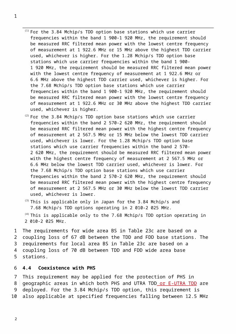
Annex 1
CDMA Direct Spread (universal terrestrial radio access(UTRA) FDD) mobile stations
1 Measurement uncertainty
Values specified in this Annex differ from those specified in Recommendation ITU-R M.1457 since values in this Annex incorporate test tolerances defined in Recommendation ITU-R M.1545.
2 Spectrum mask
2.1 UTRA spectrum mask
The spectrum emission mask of the MS applies to frequencies, which are between 2.5 MHz and 12.5 MHz away from the MS centre carrier frequency. The out-of-channel emission is specified relative to the root raised cosine (RRC) filtered mean power of the UE carrier, where the RRC filtered mean power is the mean power measured through a root raised cosine filter with a roll-off factor of 0.22 and a bandwidth equal to the chip rate of 3.84 MHz. The power of any UE emission should not exceed the levels specified in Table 1.
The absolute requirement is based on a −48.5 dBm/3.84 MHz minimum power threshold for the UE. This limit is expressed for the narrower measurement bandwidths as −54.3 dBm/1 MHz and −69.6 dBm/30 kHz.
1
1234
5
67
8
9
101112131415
161718
2

TABLE 1
Spectrum emission mask requirement (UTRA FDD MS)
Δf in MHz(Note 1)
Minimum requirement (Note 2) Additional requirements
Band II, Band IV, and Band V, and
Band X (Note 3)
Measurement bandwidth
(Note 6)Relative requirement
Absolute requirement (in measurement bandwidth)
2.5-3.5 −69.6 dBm −15 dBm 30 kHz (Note 4)
3.5-7.5 −54.3 dBm −13 dBm (Note 7) 1 MHz (Note 5)
7.5-8.5 −54.3 dBm −13 dBm (Note 7) 1 MHz (Note 5)
8.5-12.5 −47.5 dBc −54.3 dBm −13 dBm (Note 7) 1 MHz (Note 5)
NOTE 1 – f is the separation between the carrier frequency and the centre of the measurement bandwidth.NOTE 2 – The minimum requirement is calculated from the relative requirement or the absolute requirement, whichever is the higher power.NOTE NOTE 3: – For operation in Band Band II, Band IV, and Band V, and Band X only, the minimum requirement is calculated from the minimum requirement calculated in Note Note 2 or the additional requirement for band Band II, IV, V, X, whichever is the lower power.NOTE 4 – The first and last measurement positions with a 30 kHz filter at f equals 2.515 MHz and 3.485 MHz.NOTE 5 – The first and last measurement positions with a 1 MHz filter at f equals 4 MHz and 12 MHz.NOTE 6 – As a general rule, the resolution bandwidth of the measuring equipment should be equal to the measurement bandwidth. However, to improve measurement accuracy, sensitivity and efficiency, the resolution bandwidth may be smaller than the measurement bandwidth. When the resolution bandwidth is smaller than the measurement bandwidth, the result should be integrated over the measurement bandwidth in order to obtain the equivalent noise bandwidth of the measurement bandwidth.NOTE 7 – For operation in Band V, the measurement bandwidth of this requirement shall be 100 kHz.
2.2 E-UTRA spectrum mask
The output UE transmitter spectrum consists of the three components; the emission within the occupied bandwidth (channel bandwidth), the Out Of Band (OOB) emissions and the far out spurious emission domain (Figure 1).
1
1
2
3
456
2

FIGURE 1
The spectrum emission mask of the MS applies to frequencies (ΔfOOB) starting from the ± edges of the assigned E-UTRA channel bandwidth. For frequencies greater than (ΔfOOB) as specified in Table 1a the spurious requirements in §4 are applicable.
2.2.1 E-UTRA spectrum mask
The power of any MS emission shall not exceed the levels specified in Table 1a for the specified channel bandwidths.
TABLE 1A
E-UTRA spectrum emission mask
ΔfOOB
(MHz)Spectrum emission limit (dBm)/ Channel bandwidth
1.4MHz
3.0MHz
5MHz
10MHz
15MHz
20MHz
Measurement bandwidth
0-1 -13.5 -16.5 -18.5 -19.5 30 kHz 1-2.5 -8.5 -8.5 -8.5 -8.5 1 MHz 2.5-2.8 -8.5 -8.5 -8.5 -8.5 1 MHz 2.8-5 -8.5 -8.5 -8.5 -8.5 1 MHz 5-6 -11.5 -11.5 -11.5 -11.5 1 MHz 6-10 -23.5 -11.5 -11.5 -11.5 1 MHz 10-15 -23.5 -11.5 -11.5 1 MHz 15-20 -23.5 -11.5 1 MHz 20-25 -23.5 1 MHz
NOTE – As a general rule, the resolution bandwidth of the measuring equipment should be equal to the measurement bandwidth. However, to improve measurement accuracy, sensitivity and efficiency, the resolution bandwidth may be smaller than the measurement bandwidth. When the resolution bandwidth is smaller than the measurement bandwidth, the result should be integrated over the measurement bandwidth in order to obtain the equivalent noise bandwidth of the measurement bandwidth.
Note- the values for 1.4 MHz and 3.0 MHz channel bandwidths will be addressed at a later stage
1
1
23
456
7
89
10
11
121314151617
18
2
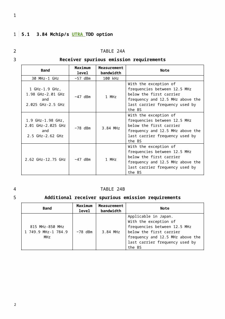
3 Adjacent channel leakage power ratio (ACLR)
3.1 UTRA ACLR
ACLR is the ratio of the RRC filtered mean power centred on the assigned channel frequency to the RRC filtered mean power centred on an adjacent channel frequency.
The limit for ACLR should be as specified in Table 2.
TABLE 2
MS ACLR limits
3.2 E-UTRA ACLR
ACLR is the ratio of the filtered mean power centred on the assigned channel frequency to the filtered mean power centred on an adjacent channel frequency. The ACLR requirements are specified for two scenarios: for (an) adjacent E -UTRA and/or UTRA channels (Figure 2).
FIGURE 2
E-UTRAACLR1 UTRA ACLR2 UTRAACLR1
RB
E-UTRA channel
Channel
ΔfOOB
3.2.1 Limits for E-UTRA
E-UTRA Adjacent Channel Leakage power Ratio (E-UTRAACLR) is the ratio of the filtered mean power centred on the assigned channel frequency to the filtered mean power centred on an adjacent channel frequency. The E-UTRA on channel and adjacent channel power is measured with a rectangular measurement bandwidth filter. The limits should be as specified in Table 2a.
Power class MS channel offset below the first or above the last carrier
frequency used(MHz)
ACLR limit(dB)
3, 4 5 32.23, 4 10 42.2
1
1
2
3
45
6
7
8
9
101112
13
1415
16171819
2
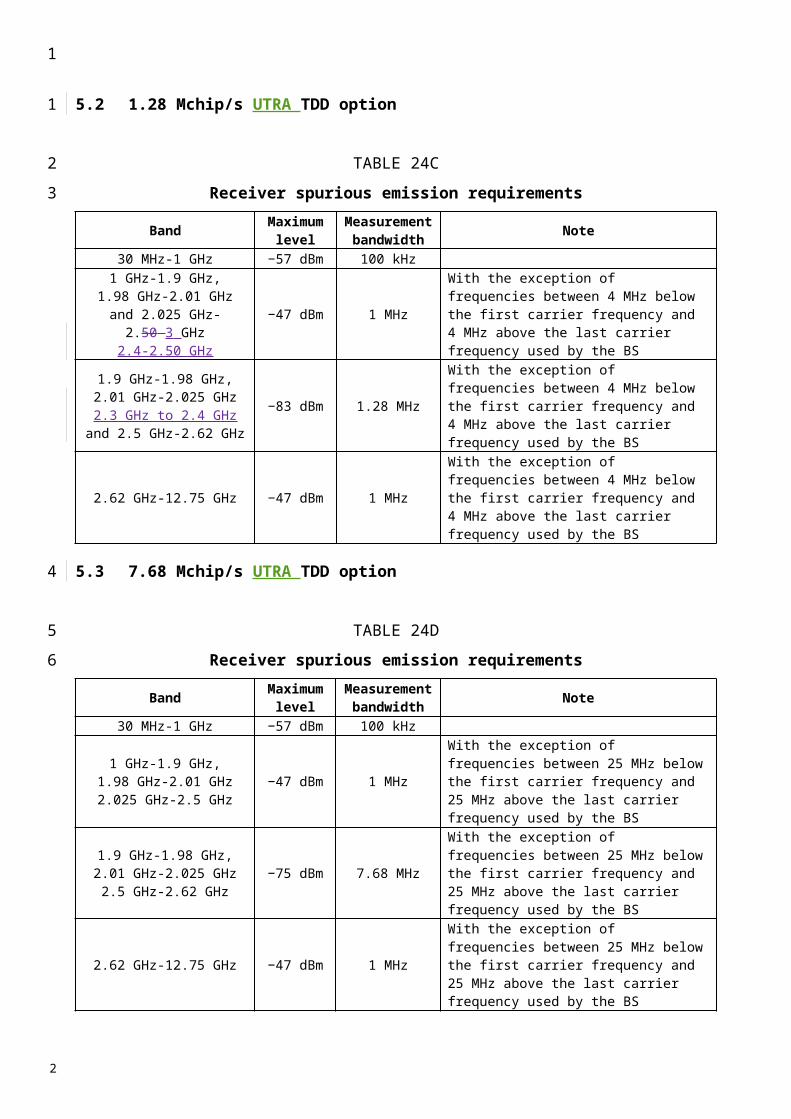
TABLE 2a
General requirements for E-UTRAACLR
Channel bandwidth / E-UTRAACLR1 / measurement bandwidth
1.4
MHz
3.0
MHz
5
MHz
10
MHz
15
MHz
20
MHz
E-UTRAACLR1 29.2 dB 29.2 dB 29.2 dB 29.2 dB 29.2 dB 29.2 dB
E-UTRA channel Measurement bandwidth
4.5 MHz 9.0 MHz 13.5 MHz
18 MHz
UE channel +5MHz or
-5MHz
+10MHz or
-10MHz
+15MHz or -
15MHz
+20MHz or
-20MHz
3.2.2 Limits for E-UTRA for UTRA co-existence in the same geographical area
For adjacent UTRA carriers the limits should be as specified in Table 2b.
UTRA Adjacent Channel Leakage power Ratio (UTRAACLR) is the ratio of the filtered mean power centred on the assigned E-UTRA channel frequency to the filtered mean power centred on an adjacent(s) UTRA channel frequency.
UTRA Adjacent Channel Leakage power Ratio is specified for both the first UTRA 5 MHz adjacent channel (UTRAACLR1) and the 2nd UTRA 5MHz adjacent channel (UTRAACLR2) .The UTRA channel is measured with a 3.84 MHz RRC bandwidth filter with roll-off factor =0.22. The E-UTRA channel is measured with a rectangular measurement bandwidth filter.
TABLE 2b
Additional requirements
Channel bandwidth / UTRAACLR1/2 / measurement bandwidth
1.4MHz
3.0MHz
5MHz
10MHz
15MHz
20MHz
UTRAACLR1 32.2 dB 32.2 dB 32.2 dB 32.2 dB 32.2 dB 32.2 dBUTRAACLR2 - - 35.2 dB 35.2 dB 35.2 dB 35.2 dBE-UTRA channel Measurement bandwidth
- 4.5 MHz 9.0 MHz 13.5 MHz 18 MHz
UTRA channel Measurement bandwidth
- - 3.84 MHz 3.84 MHz 3.84 MHz 3.84 MHz
UE channel for UTRA ACLR1
+2.5MHz from upper band edge or -2.5MHz from lower band edge
UE channel for UTRA ACLR2
+7.5MHz from upper band edge or -7.5MHz from lower band edge
1
1
2
3
4
5
678
9101112
13
14
15
2
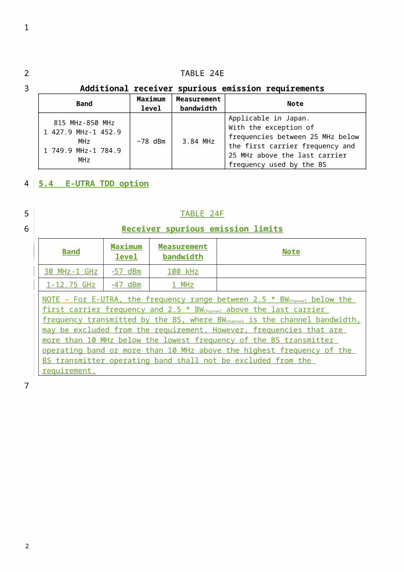
3.2.3 Additional ACLR limits
Additional ACLR requirements are signalled by the network to indicate that the UE shall meet an additional requirement for a specific deployment scenario as part of the cell handover/broadcast message.
The additional ACLR limits are specified for the 2nd UTRA 5MHz adjacent channel (UTRAACLR2). The UTRA channel is measured with a 3.84 MHz RRC bandwidth filter with roll-off factor =0.22. The E-UTRA channel is measured with a rectangular measurement bandwidth filter.
TABLE 2c
Additional requirements (UTRAACLR2)
Channel bandwidth / UTRAACLR2 / measurement bandwidth
1.4MHz
3.0MHz
5MHz
10MHz
15MHz
20MHz
UTRAACLR2bis - - 42.2 dB 42.2 dB - -E-UTRA channel Measurement bandwidth
- - 4.5 MHz 9.0 MHz - -
UTRA channel Measurement bandwidth
- - 3.84 MHz 3.84 MHz - -
UE channel for UTRAACLR2bis
+7.5MHz from upper band edge or -7.5MHz from lower band edge
4 Transmitter spurious emissions (conducted)
4.1 Transmitter spurious emissions for UTRA
For UTRA, theThe limits shown in Tables 3 and 4 are only applicable for frequencies which are greater than 12.5 MHz away from the MS centre carrier frequency.
TABLE 3
General spurious emissions requirements
Frequency bandwidth Measurement bandwidth Minimum requirement(dBm)
9 kHz f 150 kHz 1 kHz –36150 kHz f 30 MHz 10 kHz –3630 MHz f 1 000 MHz 100 kHz –36
1 GHz f 12.75 GHz 1 MHz –30
1
1
234
567
8
9
10
11
1213
14
15
16
2
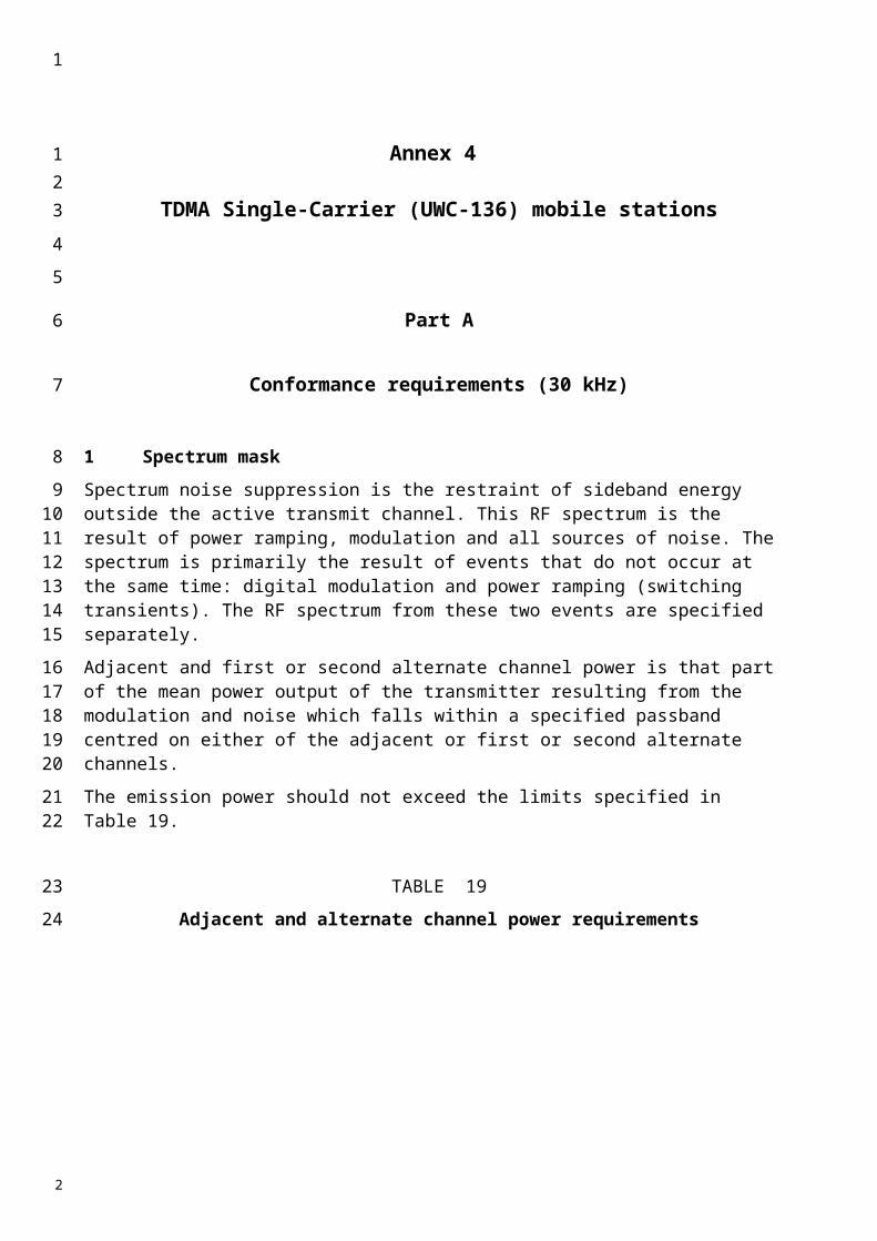
TABLE 4
Additional spurious emissions requirements for UTRA
Operating Band Frequency bandwidth Measurement
bandwidth Minimum requirement
I 860 MHz f 895 MHz 3.84 MHz −60 dBm921 MHz f < 925 MHz 100 kHz −60 dBm (see Note 1)
925 MHz f 935 MHz 100 kHz3.84 MHz
−67 dBm (see Note 1)−60 dBm
935 MHz < f 960 MHz 100 kHz −79 dBm (see Note 1) 1 475.9 MHz f 1 500.9 MHz 3.84 MHz -60 dBm
1 805 MHz f 1 880 MHz 100 kHz −71 dBm (see Note 1)1 844.9 MHz f 1 879.9 MHz 3.84 MHz −60 dBm
1 884.5 MHz < f < 1 919.6 MHz 300 kHz −41 dBm2 110 MHz f 2 170 MHz 3.84 MHz −60 dBm
2 620 MHz f 2 690 MHz 3.84 MHz −60 dBmII 869 MHz f 894 MHz 3.84 MHz −60 dBm
1 930 MHz f 1 990 MHz 3.84 MHz −60 dBm 2 110 MHz f 2 155 MHz 3.84 MHz −60 dBm
2 110 MHz f 2 170 MHz 3.84 MHz −60 dBm
1
1
2
3
2
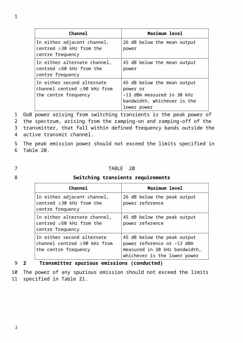
TABLE 4 (cont’)
Operating Band Frequency bandwidth Measurement
bandwidthMinimum requirement
III 921 MHz f < 925 MHz 100 kHz −60 dBm (see Note 1)
925 MHz f 935 MHz 100 kHz3.84 MHz
−67 dBm (see Note 1)−60 dBm
935 MHz < f 960 MHz 100 kHz −79 dBm (see Note 1)
1 805 MHz f 1 880 MHz 3.84 MHz −60 dBm2 110 MHz f 2 170 MHz 3.84 MHz −60 dBm
2 620 MHz f 2 690 MHz 3.84 MHz −60 dBmIV 869 MHz f 894 MHz 3.84 MHz −60 dBm
1 930 MHz f 1 990 MHz 3.84 MHz −60 dBm 2 110 MHz f 2 155 MHz 3.84 MHz −60 dBm
2 110 MHz f 2 170 MHz 3.84 MHz −60 dBmV 869 MHz f 894 MHz 3.84 MHz −60 dBm
1 930 MHz f 1 990 MHz 3.84 MHz −60 dBm 2 110 MHz f 2 155 MHz 3.84 MHz −60 dBm
2 110 MHz f 2 170 MHz 3.84 MHz −60 dBmVI 860 MHz f < 875 MHz 1 MHz −37 dBm
875 MHz f 895 MHz 3.84 MHz −60 dBm 1 475.9 MHz f 1 500.9 MHz 3.84 MHz -60 dBm
1 844.9 MHz f 1 879.9 MHz 3.84 MHz −60 dBm1 884.5 MHz f 1 919.6 MHz 300 kHz −41 dBm
2 110 MHz f 2 170 MHz 3.84 MHz −60 dBmVII 921 MHz f < 925 MHz 100 kHz −60 dBm (see Note 1)
925 MHz f 935 MHz 100 kHz3.84 MHz
−67 dBm (see Note 1)−60 dBm
935 MHz < f 960 MHz 100 kHz −79 dBm (see Note 1)1 805 MHz f 1 880 MHz 100 kHz −71 dBm (see Note 1)
2 110 MHz f 2 170 MHz 3.84 MHz −60 dBm2 620 MHz f 2 690 MHz 3.84 MHz −60 dBm
2 590 MHz f 2 620 MHz 3.84 MHz −50 dBmVIII 925 MHz f 935 MHz 100 kHz
3.84 MHz−67 dBm (see Note 1)
−60 dBm
935 MHz < f 960 MHz 100 kHz3.84 MHz
−79 dBm (see Note 1)−60 dBm
1 805 MHz < f 1 830 MHz 100 kHz3.84 MHz
−71 dBm (see Notes 1 and 2)−60 dBm (see Note 2)
1 830 MHz < f 1 880 MHz 100 kHz3.84 MHz
−71 dBm (see Note 1)−60 dBm
2 110 MHz f 2 170 MHz 3.84 MHz −60 dBm
2 620 MHz f 2 640 MHz 3.84 MHz −60 dBm2 640 MHz < f 2 690 MHz 3.84 MHz −60 dBm (see Note 2)
1
1
2

TABLE 4 (end)
Operating Band Frequency bandwidth Measurement
bandwidthMinimum requirement
IX 860 MHz f 895 MHz 3.84 MHz −60 dBm 1 475.9 MHz f 1 500.9 MHz 3.84 MHz -60 dBm
1 844.9 MHz f 1 879.9 MHz 3.84 MHz −60 dBm1 884.5 MHz f 1 919.6 MHz 300 kHz −41 dBm
2 110 MHz f 2 170 MHz 3.84 MHz −60 dBmX 869 MHz f 894 MHz 3.84 MHz −60 dBm
1 930 MHz f 1 990 MHz 3.84 MHz −60 dBm2 110 MHz f 2 170 MHz 3.84 MHz −60 dBm
XI 860 MHz f 895 MHz 3.84 MHz -60 dBm 1 475.9 MHz f 1 500.9 MHz 3.84 MHz -60 dBm
1 844.9 MHz f 1 879.9 MHz 3.84 MHz -60 dBm 1 884.5 MHz f 1 919.6 MHz 300 kHz -41 dBm
2 110 MHz f 2 170 MHz 3.84 MHz -60 dBmNOTE 1 – The measurements are made on frequencies which are integer multiples of 200 kHz. As exceptions, up to five measurements with a level up to the applicable requirements defined in Table 3 are permitted for each channel used in the measurement.NOTE 2 – The measurements are made on frequencies which are integer multiples of 200 kHz. As exceptions, measurements with a level up to the applicable requirements defined in Table 3 are permitted for each channel used in the measurement due to second or third harmonic spurious emissions.
4.2 Transmitter spurious emissions for E-UTRA
For E-UTRA, the spurious emission limits apply for frequency ranges that are more than ΔfOOB (MHz) from the edge of the channel bandwidth (Table 3a).
TABLE 3a
Boundary between E-UTRA ΔfOOB and spurious emission domain
Channel bandwidth
1.4MHz
3.0MHz
5MHz
10MHz
15MHz
20MHz
ΔfOOB (MHz) 10 15 20 25
Note- the values for 1.4 MHz and 3.0 MHz channel bandwidths will be addressed at a later stage
The spurious emission limits in Table 3b apply for all E-UTRA transmitter band configurations and channel bandwidths.
TABLE 3b
Spurious emissions limits
1
1
2
34
5
6
7
89
10
11
2
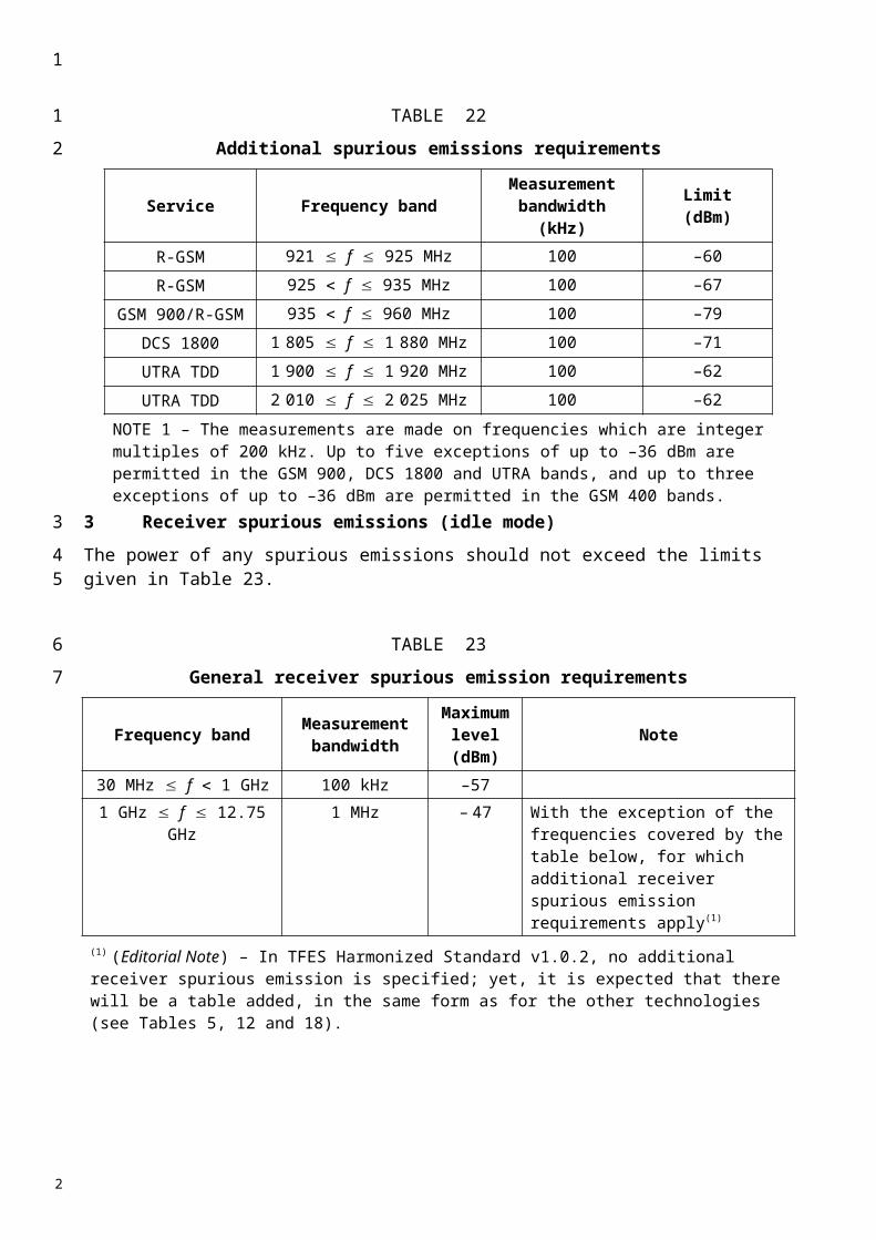
Table 4b specifies the requirements for the specified E-UTRA band
TABLE 4b
Spurious emissions requirements for UE co-existence in E-UTRA bands
E-UTRA Band
Spurious emission Protected band Frequency range
(MHz)Level (dBm)
Bandwidth (MHz)
Comment
1 E-UTRA Band 1, 3, 7, 8, 9, 11, 34, 38, 40 FDL_low - FDL_high -50 1 Frequency range 860 - 895 -50 1Frequency range 1884.5 - 1919.6 -41 0.3 E-UTRA band 33 1900 - 1920 -50 1 Note 3 E-UTRA band 39 1880 - 1920 -50 1 Note 3
2 E-UTRA Band 2, 4, 5, 10, 13, 14 FDL_low - FDL_high -50 1 3 E-UTRA Band 1, 3, 7, 8, 9, 11, 33, 34, 38 FDL_low - FDL_high -50 1 4 E-UTRA Band 2, 4, 5, 10, 13, 14 FDL_low - FDL_high -50 1 5 E-UTRA Band 2, 4, 5, 10, 13, 14 FDL_low - FDL_high -50 1 6 E-UTRA Band 1, 9, 11, 34 FDL_low - FDL_high -50 1
Frequency range 860 - 875 -37 1Frequency range 875 - 895 -50 1Frequency range 1884.5 - 1919.6 -41 0.3
7 E-UTRA Band 1, 3, 7, 8, 33, 34 FDL_low - FDL_high -50 1 E-UTRA Band 38 2570 - 2620 -50 1 Note 3
8 E-UTRA Band 1, 8, 7, 33, 34, 38, 39, 40 FDL_low - FDL_high -50 1 E-UTRA band 3 1805 - 1830 -50 1 Note 4 E-UTRA band 3 1805 - 1880 -36 0.1 Note 2,4 E-UTRA band 3 1830 - 1880 -50 1 Note 4 E-UTRA band 7 2640 - 2690 -50 1 Note 4 E-UTRA band 7 2640 - 2690 -36 0.1 Note 2,4
9 E-UTRA Band 1, 9, 11, 34 FDL_low - FDL_high -50 1 Frequency range 860 - 895 -50 1Frequency range 1884.5 - 1919.6 -41 0.3
10 E-UTRA Band 2, 4, 5, 10, 13, 14 FDL_low - FDL_high -50 1 11 E-UTRA Band 1, 9, 11, 34 FDL_low - FDL_high -50 1
Frequency range 860 - 895 -50 1Frequency range 1884.5 - 1919.6 -41 0.3
13 E-UTRA Band 2, 4, 5, 10, 13, 14 FDL_low - FDL_high -50 1 Frequency range 763 - 775 -35 0.00625
14 E-UTRA Band 2, 4, 5, 10, 13, 14 FDL_low - FDL_high -50 1 Frequency range 763 - 775 -35 0.00625
Note 1 FDL_low and FDL_high refer to each E-UTRA frequency band specified in Note 2 of the Scope
2 A number of exceptions are permitted and is FFS. These exceptions include both spurious due to LO mixing and I/Q imbalance for specific values of NRB. For these exceptions the requirements of Table 3b are applicable.
3 To meet these requirements some restriction will be needed for either the operating band or protected band
4 Requirements are specified in terms of E-UTRA sub-bands
5 For non synchronised TDD operation to meet these requirements some restriction will be needed for either the operating band or protected band
Frequency range Measurement bandwidth Maximum level 9 kHz f 150 kHz 1 kHz –36 dBm 150 kHz f 30 MHz 10 kHz –36 dBm
30 MHz f 1 000 MHz 100 kHz –36 dBm 1 GHz f 12.75 GHz 1 MHz –30 dBm
1
1
2
3
4
2
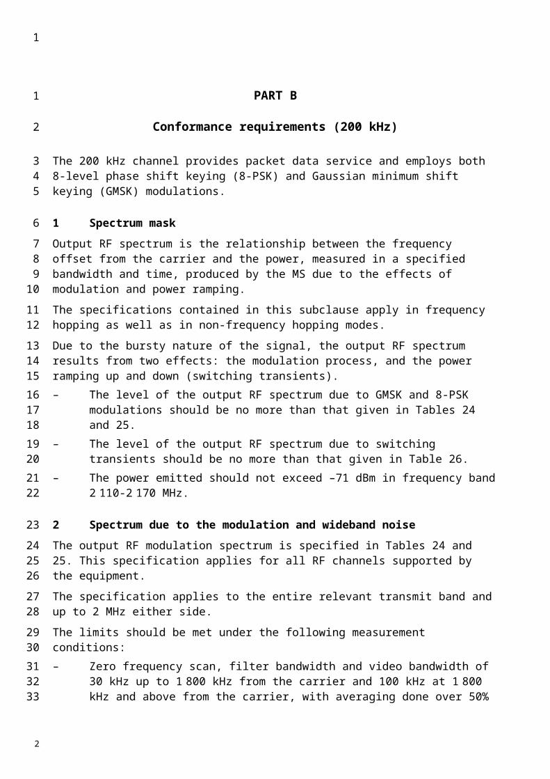
5 Receiver spurious emissions (conducted)
The spurious emissions power is the power of emissions generated or amplified in a receiver that appear at the UE antenna connector.
5.1 Receiver spurious emissions for UTRA
For UTRA, the power of any narrow-band continuous wave (CW) spurious emission should not exceed the maximum level specified in Tables 5 and 6.
TABLE 5
General receiver spurious emission requirements
For UTRA the following additional spurious emission limits are applicable
TABLE 6
Additional receiver spurious emission requirements
Band Frequency band Measurement bandwidth
Maximum level Note
I 860 MHz f 895 MHz 3.84 MHz −60 dBm
921 MHz f < 925 MHz 100 kHz −60 dBm*
925 MHz f 935 MHz 100 kHz3.84 MHz
−67 dBm*−60 dBm
935 MHz < f 960 MHz 100 kHz −79 dBm*
1 805 MHz f 1 880 MHz 100 kHz −71 dBm*1 475.9 MHz f 1 500.9 MHz 3.84 MHz −60 dBm
1 844.9 MHz f 1 879.9 MHz 3.84 MHz −60 dBm
1 920 MHz f 1 980 MHz 3.84 MHz −60 dBm UE transmit band in URA_PCH, Cell_PCH and idle state
2 110 MHz f 2 170 MHz 3.84 MHz −60 dBm UE receive band
2 620 MHz f 2 690 MHz 3.84 MHz −60 dBmII 869 MHz f 894 MHz 3.84 MHz −60 dBm
1 850 MHz f 1 910 MHz 3.84 MHz −60 dBm UE transmit band in URA_PCH, Cell_PCH and idle state
1 930 MHz f 1 990 MHz 3.84 MHz −60 dBm UE receive band 2 110 MHz f 2 170 MHz 3.84 MHz −60 dBm
Frequency band Measurement bandwidth
Maximum level Note
30 MHz f 1 GHz 100 kHz −57 (dBm)1 GHz f 12.75 GHz 1 MHz −47 (dBm)
1
1
23
4
56
7
8
10
11
12
2
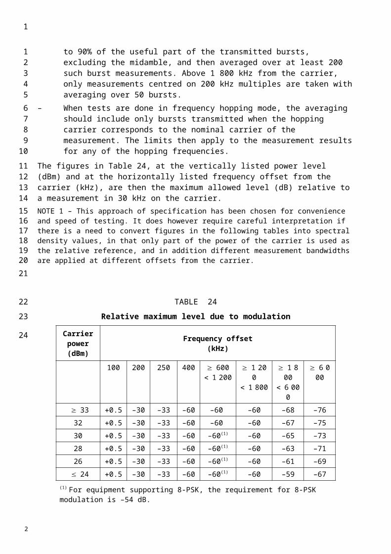
TABLE 6 (cont’)
Additional receiver spurious emission requirements
Band Frequency band Measurement bandwidth
Maximum level Note
III 921 MHz f < 925 MHz 100 kHz −60 dBm*
925 MHz f 935 MHz 100 kHz3.84 MHz
−67 dBm*−60 dBm
935 MHz < f 960 MHz 100 kHz −79 dBm*
1 710 MHz f 1 785 MHz 3.84 MHz −60 dBm UE transmit band in URA_PCH, Cell_PCH and idle state
1 805 MHz f 1 880 MHz 3.84 MHz −60 dBm UE receive band 2 110 MHz f 2 170 MHz 3.84 MHz −60 dBm
2 620 MHz f 2 690 MHz 3.84 MHz −60 dBmIV 869 MHz f < 894 MHz 3.84 MHz −60 dBm
1 710 MHz f < 1 755 MHz 3.84 MHz −60 dBm UE transmit band in URA_PCH, Cell_PCH and idle state
1 930 MHz f 1 990 MHz 3.84 MHz −60 dBm2 110 MHz f 2 170 MHz 3.84 MHz −60 dBm UE receive band (see note 1)
2 110 MHz f 2 170 MHz 3.84 MHz −60 dBm UE receive band (see note 2) V 824 MHz f 849 MHz 3.84 MHz −60 dBm UE transmit band in URA_PCH,
Cell_PCH and idle state869 MHz f < 894 MHz 3.84 MHz −60 dBm UE receive band
1 930 MHz f 1 990 MHz 3.84 MHz −60 dBm 2 110 MHz f 2 170 MHz 3.84 MHz −60 dBm
VI 815 MHz f 850 MHz 3.84 MHz −60 dBm UE in URA_PCH, Cell_PCH and idle state
860 MHz f 895 MHz 3.84 MHz −60 dBm UE in URA_PCH, Cell_PCH and idle state
1 475.9 MHz f 1 500.9 MHz 3.84 MHz −60 dBm1 844.9 MHz f 1 879.9 MHz 3.84 MHz −60 dBm
2 110 MHz f 2 170 MHz 3.84 MHz −60 dBmVII 921 MHz f < 925 MHz 100 kHz −60 dBm *
925 MHz f 935 MHz 100 kHz−3.84 MHz
−67 dBm*−60 dBm
935 MHz < f 960 MHz 100 kHz −79 dBm*1 805 MHz f 1 880 MHz 100 kHz −71 dBm*
2 110 MHz f 2 170 MHz 3.84 MHz −60 dBm
2 500 MHz f 2 570 MHz 3.84 MHz −60 dBm UE transmit band in URA_PCH, Cell_PCH and idle state
2 620 MHz f 2 690 MHz 3.84 MHz −60 dBm UE receive band
1
1
2
3
2

TABLE 6 (end)
Band Frequency band Measurement bandwidth
Maximum level Note
VIII 880 MHz f 915 MHz 3.84 MHz −60 dBm UE in URA_PCH, Cell_PCH and idle state 921 MHz f < 925 MHz 100 kHz −60 dBm*
925 MHz f MHz 100 kHz3.84 MHz
−67 dBm*−60 dBm
935 MHz < f 960 MHz 100 kHz −79 dBm*1 805 MHz < f 1 880 MHz 3.84 MHz −60 dBm2 110 MHz f 2 170 MHz 3.84 MHz −60 dBm2 620 MHz f 2 690 MHz 3.84 MHz −60 dBm
IX 860 MHz f 895 MHz 3.84 MHz −60 dBm1 475.9 MHz f 1 500.9 MHz 3.84 MHz −60 dBm
1 749.9 MHz f 1 784.9 MHz 3.84 MHz −60 dBm UE transmit band in URA_PCH, Cell_PCH and idle state
1 844.9 MHz f 1 879.9 MHz 3.84 MHz −60 dBm UE receive band2 110 MHz f 2 170 MHz 3.84 MHz −60 dBm
X 869 MHz f < 894 MHz 3.84 MHz −60 dBm
1 710 MHz f < 1 770 MHz 3.84 MHz −60 dBm UE transmit band in URA_PCH, Cell_PCH and idle state
1 930 MHz f 1 990 MHz 3.84 MHz −60 dBm2 110 MHz f 2 170 MHz 3.84 MHz −60 dBm UE receive band
XI 860 MHz f 895 MHz 3.84 MHz −60 dBm1 427.9 MHz f 1 452.9 MHz 3.84 MHz −60 dBm UE transmit band 1 475.9 MHz f 1 500.9 MHz 3.84 MHz −60 dBm UE receive band1 844.9 MHz f 1 879.9 MHz 3.84 MHz −60 dBm 2 110 MHz f 2 170 MHz 3.84 MHz −60 dBm
* The measurements are made on frequencies which are integer multiples of 200 kHz. As exceptions, up to five measurements with a level up to the applicable requirements defined in Table 5 are permitted for each channel used in the measurement.NOTE 1 – For UEs that conform to Release 6 and support Band IV shall support the defined frequency bandwidth.NOTE 2 – For UEs that conform to Release 7 and later releases and support Band IV shall support the defined frequency bandwidth.
5.2 Receiver spurious emissions for E-UTRA
The power of any narrow band CW spurious emission shall not exceed the maximum level specified in Table 7.
TABLE 7
General receiver spurious emission requirements for E-UTRAFrequency Band Measurement
BandwidthMaximum
levelNote
30MHz f < 1GHz 100 kHz -57 dBm1GHz f 12.75 GHz 1 MHz -47 dBm
1
1
2
34
5
6
2
Annex 2
IMT 2000 CDMA Multi-Carrier (CDMA-2000) mobile stationsNO CHANGES
NOTE – Single carrier HRPD spectrum emission mask or spurious emission limits are only applicable for spreading Rate 1.
1 Spectrum maskMask
1.1 Spreading Rate 1
When transmitting with sSpreading rRate 1, the spectrum emissions mask for Band Classes 0, 2, 5, 7, 9, 10, 11 and 12 should shall be less than the limits specified in Table 71.
TABLE 7
Transmitter spectrum emission limits for spreading rate 1
TABLE 1
Band Classes 0, 2, 5, 7, 9, 10, 11 and 12 Spectrum Emission Mask for spreading Rate 1
When transmitting with Spreading Rate 1, the spectrum emission mask for Band Classes 1, 4, 6, 8, 13, 14 and 15 shall be less than the limits specified in Table 2.
For |f | within the range(MHz)
Emission limit
1.25-1.98 Less stringent of –42 dBc/30 kHz or –54 dBm/1.23 MHz
1.98-2.25 Less stringent of –50 dBc/30 kHz or –54 dBm/1.23 MHz
2.25-4 –(13 + 1 (f – 2.25 MHz)) dBm/1 MHz
NOTE 1 – All frequencies in the measurement bandwidth should satisfy the restrictions on |f | where f centre frequency – closer edge frequency, f, of the measurement filter.
For |f | within the Range(MHz) Emission Limit
885-1.98 Less stringent of –42 dBc/30 kHz or –54 dBm/1.23 MHz1.25 to 4.00
(Band Class 10 only) –13 dBm/30 kHz
1.98-4.00 Less stringent of –54 dBc/30 kHz or –54 dBm/1.23 MHz2.25-4.00
(Band Class 7 only) –35 dBm/6.25 kHz
NOTE 1 – All frequencies in the measurement bandwidth shall satisfy the restrictions on |f | where f centre frequency – closer edge frequency, f, of the measurement filter.
1
123
4
5
67
8
9
1011
12
13
14
15
1718
2
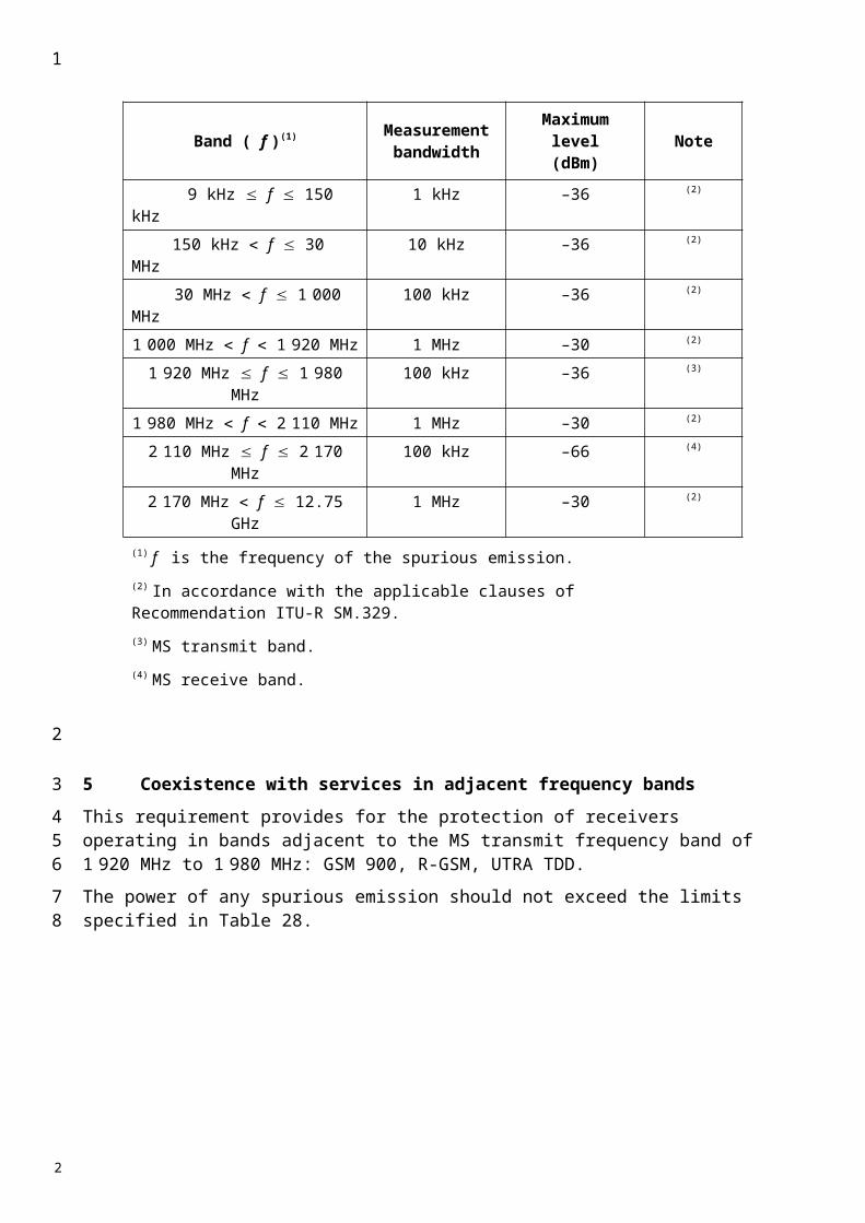
TABLE 2
Band Classes 1, 4, 6, 8, 13, 14 and 15 Spectrum Emission Mask for spreading Rate 1
When transmitting in Band Class 3, the spectrum emission mask shall be less than the limits specified in Table 3.
For |f | within the Range(MHz) Emission Limit
1.25 to 1.98 less stringent of -42 dBc/30 kHz or -54 dBm/1.23 MHz
1.98 to 4.00 less stringent of-50 dBc/30 kHz or -54 dBm/1.23 MHz
2.25 to 4.00(Band Classes 6, 8 and 13
only)-[13 + 1 (f – 2.25 MHz)] dBm/1 MHz
NOTE 1 – All frequencies in the measurement bandwidth shall satisfy the restrictions on |f | where f = centre frequency – closer edge frequency, f, of the measurement filter.
1
1
2
45
2
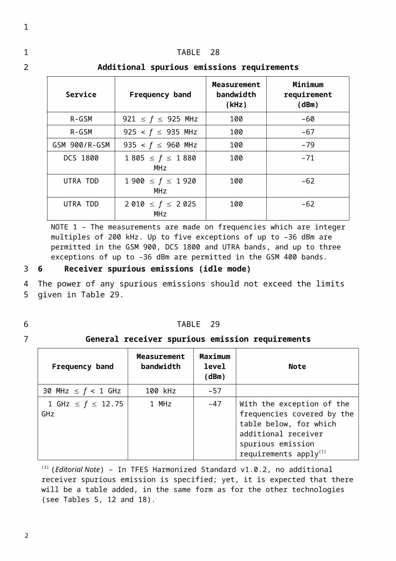
TABLE 3
Band Class 3 Spectrum Emission Mask for Spreading Rate 1
Measurement Frequency (MHz)
For |f| within the Range
Emission Limit
> 815 and 850,> 887 and 889,> 893 and 901,> 915 and 925
900 kHzand< 1.98 MHz
-42 dBc / 30 kHz
1.98 MHz25 mW (-16 dBm) / 100 kHz; Pout 30 dBm
-54 dBc / 100 kHz; Pout > 30 dBm
> 885 and 958,except> 887 and 889,> 893 and 901,> 915 and 925
< 1.98 MHz25 mW (-16 dBm) / 30 kHz; Pout 30 dBm
Less stringent of -60 dBc / 30 kHz or 2.5 mW (-26 dBm) / 30 kHz; Pout > 30 dBm
1.98 MHz25 mW (-16 dBm) / 100 kHz; Pout 30 dBm
Less stringent of -60 dBc / 100 kHz or 2.5 mW (-26 dBm) / 100 kHz; Pout > 30 dBm
885 and> 958,except 815-850
< 1.98 MHz25 mW (-16 dBm) / 30 kHz; Pout 30 dBm
Less stringent of -60 dBc / 30 kHz or 2.5 mW (-26 dBm) / 30 kHz; Pout > 30 dBm
1.98 MHz25 mW (-16 dBm) / 1 MHz; Pout 44 dBm
More stringent of -60 dBc / 1 MHz and 20 mW (13 dBm) / 1 MHz; Pout > 44 dBm
NOTE – All frequencies in the measurement bandwidth shall satisfy the restrictions on |f| where f = center frequency - closer measurement edge frequency (f). The lower and upper limits of the frequency measurement are currently 10 MHz and 3 GHz in Japan radio measurement documents.
When transmitting in Band Class 11 or 12 with spreading Rate 1, the spectrum emission mask shall also be less than the requirements in Table 4A for cdma2000 and Table 4B for HRPD.
1
1
2
345
67
2
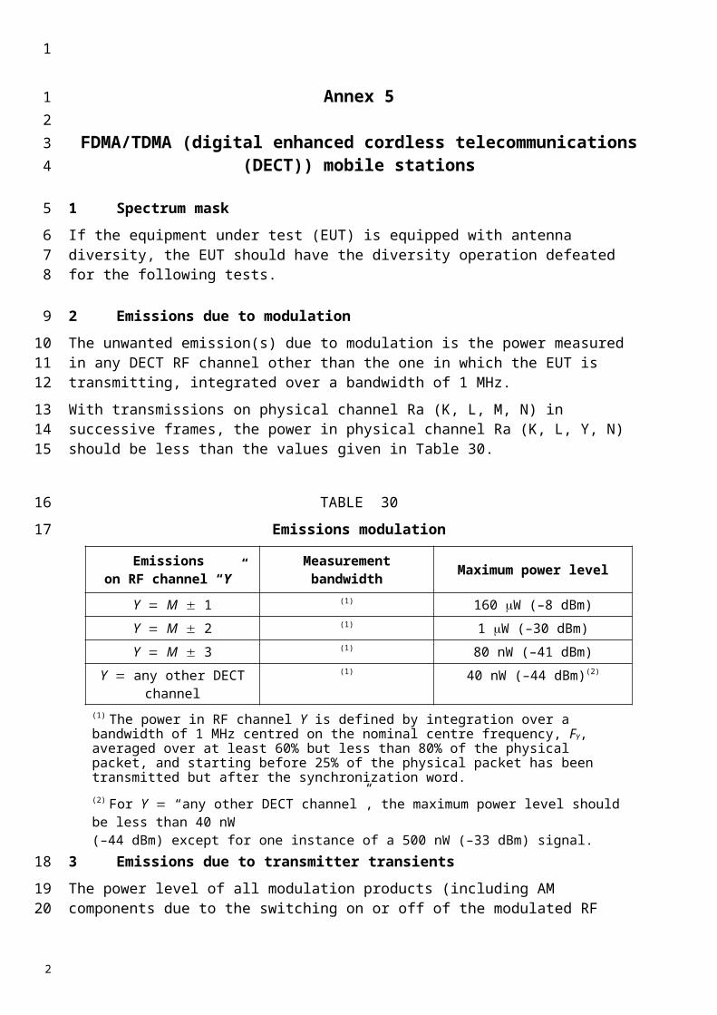
TABLE 4A
Additional cdma2000 Band Classes 11 and 12 Spectrum Emission Mask for spreading Rate 1
For |f| within the Range Emission Limit
885 to 1.125 -47 – 7 (|f| – 885) / 240 dBc in 30 kHz
1.125 to 1.98 -54 – 13 (|f| – 1125) / 855 dBc in 30 kHz
1.98 to 4.00 -67 – 15 (|f| – 1980) / 2020 dBc in 30 kHz
4.00 to 10.00 -51 dBm in 100 kHz
NOTE – All frequencies in the measurement bandwidth shall satisfy the restrictions on |f| where f = center frequency - closer measurement edge frequency (f). f is positive offset from the highest valid CDMA channel in the band subclass or negative offset from the lowest valid CDMA channel in the band subclass. The emission limits for Band Classes 11 and 12 (European PAMR bands) are designed to allow co-existence with incumbent services in Europe and are tighter than ITU Category B requirements.
TABLE 4B
Additional HRPD Band Classes 11 and 12 Spectrum Emission Mask
For |f| within the Range (MHz)
Emission Limit Band Class 11 Subclasses 4, 5; Band Class 12 Subclass 1
Emission Limit Band Class 11 Subclasses 0, 1, 2, 3; Band
Class 12 Subclass 0
.885 to 1.12 -47 – 7 (|f| – 885) / 235 dBc in 30 kHz Not specified
1.12 to 1.98 -54 – 13 (|f| – 1120) / 860 dBc in 30 kHz Not specified
1.98 to 4.00 -67 – 15 (|f| – 1980) / 2020 dBc in 30 kHz Not specified
NOTE – All frequencies in the measurement bandwidth shall satisfy the restrictions on |f| where f = center frequency - closer measurement edge frequency (f). f is positive offset from the highest valid CDMA channel in the band subclass or negative offset from the lowest valid CDMA channel in the band subclass. The emission limits for Band Classes 11 and 12 (European PAMR bands) are designed to allow co-existence with incumbent services in Europe and are tighter than ITU Category B requirements.
1.2 Multicarrier HRPD
When transmitting in Band Classes 0, 2, 3, 5, 7, 9, 10, 11 or 12 for a HRPD Rev B capable terminal configured with two reverse link channels with maximum frequency separation, the spectrum emission masks with ten or more averages shall be less than the limits specified in Table 5A.
1
1
2
345678
9
10
111213141516
17
181920
2

TABLE 5A
Band Classes 0, 2, 3, 5, 7, 9, 10, 11, and 12 Spectrum Emission Mask for Multicarrier HRPD
For ||f|| within the Range (MHz) Emission Limit
885 kHz to 1.885 6 dBm / 1 MHz
> 1.885 -13 dBm / 1 MHz
NOTE – All frequencies in the measurement bandwidth shall satisfy the restrictions on |f| where f is measured as the frequency offset from the center frequency of each reverse CDMA channel.
Emission Limits shall apply between the reverse CDMA channels when MaxReverseLinkBandwidth 41.23 MHz.
When transmitting in Band Classes 1, 4, 6, or 8 for a HRPD Rev B capable terminal configured with two reverse link channels with maximum frequency separation, the spectrum emissions mask with ten or more averages shall be less than the limits specified in Table 5B.
TABLE 5B
Band Classes 1, 4, 6, and 8 Spectrum Emission Mask for Multicarrier HRPD
For |f | within the Range (MHz) Emission Limit
1.25 to 2.25 6 dBm / 1 MHz
> 2.25 -13 dBm / 1 MHz
NOTE – All frequencies in the measurement bandwidth shall satisfy the restrictions on |f| where f where f is measured as the frequency offset from the center frequency of each channel. Emission Limits shall apply between the carriers when MaxReverseLinkBandwidth 41.25 MHz.
A single exception will be allowed for spurious emission frequencies between the two reverse CDMA channels (for both Tables 5A and 5B).
For adjacent reverse CDMA channels, the spectrum emission mask with ten or more averages shall be less than the limits specified in Tables 6A and 6B.
1
1
2
3
456
7
8
910
1112
2
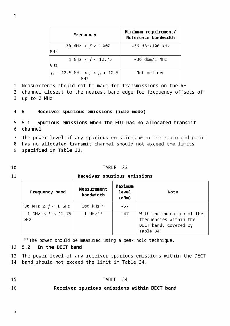
TABLE 6A
Adjacent Multi-carrier Spectrum Emission Limits for number of adjacent reverse CDMA Channels, N = 3
For |f | within the Range (MHz) Emission Limit
2.5 to 2.7 -14 dBm / 30 kHz
2.7 to 3.5 -[14 + 15 (f – 2.7 MHz)] dBm / 30 kHz
3.08 (Band Class 6 only) -33 dBc / 3.84 MHz
3.5 to 7.5 -[13 + 1 (f – 3.5 MHz)] dBm / 1 MHz
7.5 to 8.5 -[17 + 10 (f – 7.5 MHz)] dBm / 1 MHz
8.08 (Band Class 6 only) -43 dBc / 3.84 MHz
8.5 to 12.5 -27 dBm / 1 MHz
NOTE – All frequencies in the measurement bandwidth shall satisfy the restrictions on |f | where f = center frequency of the middle reverse CDMA channel- closer measurement edge frequency (f). The requirements at offsets of 3.08 and 8.08 MHz are equivalent to ACLR requirements of 33 and 43 dB from a Spreading Rate 3 mobile station transmitter into a Spreading Rate 3 or IMT-DS mobile station receiver offset by 5 and 10 MHz respectively. ITU Category B is intended to apply to only Band Classes 6, 8, 9, 11 and 12.
TABLE 6B
Adjacent multi-carrier Spectrum Emission Limits for number of adjacent reverse CDMA Channels, N≠ 3
For |f | within the Range (MHz) Emission Limit
2.5 + to 3.5 + -13 dBm / (12.5 kHz × N) kHz
3.5 + to 3.125× (N+1) -13 dBm / 1 MHz
NOTE – All frequencies in the measurement bandwidth shall satisfy the restrictions on |f | where f = center frequency - closer measurement edge frequency (f). ITU Category B is intended to apply to only Band Classes 6, 8, 9, 11 and 12. = (N-3) × 625 kHz, where N is the number of carriers (N ≥ 2). Operation outside North America is for future study.
1
1
23
4
56
7
2
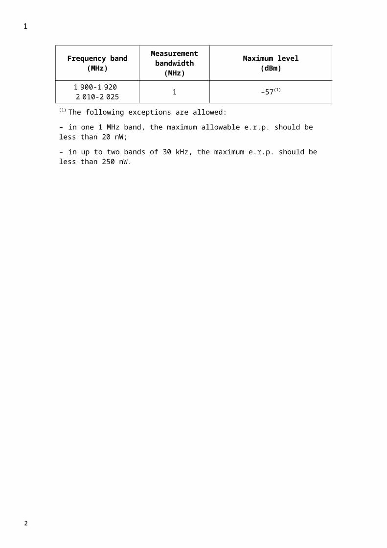
1.3 Spreading Rate 3
When transmitting with sSpreading rate Rate 3, the spectrum emissions mask shouldshall be less than the limits specified in Table 87.
TABLE 87
Transmitter sSpectrum eEmission lLimits for sSpreading rRate 3
2 Transmitter Sspurious eEmissions (cConducted)
When transmitting with spreading Spreading rate Rate 1 or sSpreading rRate 3, the spurious emissions should shall be less than the limits specified in Tables 9 8A and 108B.
TABLE 98A
Transmitter Sspurious eEmission lLimits for sSpreading rRates 1 and 3, rRespectively (Category A)
For |f | within the rRange(MHz) Emission lLimit
2.5-2.7 –14 dBm/30 kHz2.7-3.5 –(14 + 15 (f – 2.7 MHz)) dBm/30 kHz
3.08 (Band Class 6 only) –33 dBc/3.84 MHz3.5-7.5 –(13 + 1 (f – 3.5 MHz)) dBm/1 MHz7.5-8.5 –(17 + 10 (f – 7.5 MHz)) dBm/1 MHz
8.08 (Band Class 6 only) –43 dBc/3.84 MHz8.5-12.5 –27 dBm/1 MHz
NOTE 1: – All frequencies in the measurement bandwidth should shall satisfy the restrictions on |f | where f centre frequency – closer edge frequency, f, of the measurement filter.The requirements at offsets of 3.08 and 8.08 MHz are equivalent to ACLR requirements of 33 and 43 dB from a Sspreading rRate 3 mobile station transmitter into a sSpreading rRate 3 or IMT-2000 CDMA dDirect sSpread MS mobile station receiver offset by 5 and 10 MHz respectively. ITU Category B is intended to apply to only Band Classes 5, 6, 8, 9, 11 and 12.
1
1
23
4
5
6
78
9
1011
2

TABLE 8B
Transmitter Spurious Emission Limits for Spreading Rates 1 and 3, Respectively (Category B)
When transmitting with spreading Rate 1 or spreading Rate 3 in Band Class 6, the spurious emissions shall be less than the limits specified in Table 9.
TABLE 109
Additional Band Class 6 Ttransmitter sSpurious eEmission lLimits for Sspreading rRates 1 and 3, rRespectively
When transmitting in Band Class 7, the transmitter spurious emissions with ten or more averages shall also be less than the requirements in Table 10.
For |f | within the rRange Frequency bBandwidth
Measurement
bBandwidth
Emission lLimit(dBm)
> 4 MHz for Sspreading rRate 1> 12.5 MHz for spreading Spreading Rrate 3
9 kHz < f < 150 kHz150 kHz < f < 30 MHz
30 MHz < f < 1 GHz1 GHz < f < 12.75 GHz
1 kHz10 kHz
100 kHz1 MHz
–36 13 –3613–36 13 –3013
NOTE 1 – All frequencies in the measurement bandwidth should shall satisfy the restrictions on |f | where f centre frequency – closer edge frequency, f, of the measurement filter.
For |f | within the Range Frequency Bandwidth Measurement Bandwidth
Emission Limit(dBm)
> 4 MHz for spreading rate 1> 12.5 MHz for spreading rate 3
9 kHz < f < 150 kHz150 kHz < f < 30 MHz
30 MHz < f < 1 GHz1 GHz < f < 12.75 GHz
1 kHz10 kHz
100 kHz1 MHz
–36 –36–36 –30
NOTE 1 – All frequencies in the measurement bandwidth shall satisfy the restrictions on |f | where f centre frequency – closer edge frequency, f, of the measurement filter.
Measurement Ffrequency
(MHz)
Measurement Bbandwidth
(kHz)
EmissionlLimit(dBm)
Victim Bband
1 88493.5-1 919.6 300 41 PHS925-935 100 67 GSM 900935-960 100 79 GSM 900
1 805-1 880 100 71 DCS 1800NOTE 1 – Measurements apply only when the measurement frequency is at least 11.25 MHz (Sspreading rRate 1) or 12.5 MHz (spreading Spreading rate Rate 3) from the CDMA centre frequency. The non-PHS system band measurements are made on frequencies which are integer multiples of 200 kHz. As exceptions, up to five measurements with a level up to the spurious emission limits in Table 8B9 are allowed.
1
1
23
45
6
78
910
2
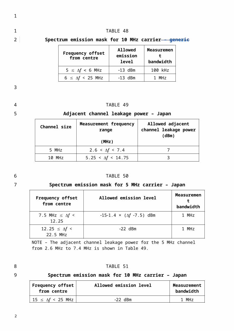
TABLE 10
Additional Band Class 7 Transmitter Spurious Emission Limits
Transmission Frequency (MHz)
Measurement Frequency (MHz) Emission Limit Victim Band
776-788 763-775 -35 dBm/6.25 kHz Public Safety788-793 769-775 -35 dBm/6.25 kHz Public Safety776-788 793-805 -35 dBm/6.25 kHz Public Safety788-793 799-805 -35 dBm/6.25 kHz Public Safety
When transmitting in Band Classes 11 and 12, the transmitter spurious emissions with ten or more averages shall also be less than the requirements in Table 11.
TABLE 11
Additional Band Classes 11 and 12 Transmitter Spurious Emission Limits
For |f| within the Range
Emission Limit Band Class 11 Subclasses 4, 5; Band Class 12
Subclass 1
Emission Limit Band Class 11 Subclasses 0, 1, 2, 3; Band Class
12 Subclass 0
4.00 MHz to 10.0 MHz -51 dBm in 100 kHz Not specified
NOTE – All frequencies in the measurement bandwidth shall satisfy the restrictions on |f| where f = center frequency – closer measurement edge frequency (f). f is positive offset from the highest valid CDMA channel in the band subclass or negative offset from the lowest valid CDMA channel in the band subclass. The emission limits for Band Classes 11 and 12 (European PAMR bands) are designed to allow co-existence with incumbent services in Europe and are tighter than ITU Category B requirements.
2 Adjacent Channel Leakage Power Ratio
For cdma2000 adjacent channel leakage power ratio (ACLR) calculation, both the transmitted power and received power are measured with a rectangular filter. For cdma2000 system, the first adjacent channel offset is 2.5 MHz and the second adjacent channel offset is 3.75 MHz for band classes in 1 900 MHz. For cellular band in 800 or 450 MHz, the first adjacent channel offset is 1.5 MHz and the second adjacent channel offset is 2.73 MHz. The receiver bandwidth is 1.23 MHz.
The limit for ACLR should be as specified in Table 12.
1
12
34
5
6
7
8
910111213
14
2

Table 12
Mobile Station ACLR Limits
Band Class ACLR1 (DB) ACLR2 (DB)
0 26.34 37.87
1 32.38 35.37
2 26.34 37.87
4 32.38 35.37
5 26.34 37.87
6 33.13 37.89
7 26.34 35.29
8 33.13 37.89
9 26.34 37.87
10 20.96 19.87
11
26.34 (HRPD)39.31 (CDMA2000 1X)
39.41 (HRPD: Band Subclasses 4 and 5 only)
37.87 (HRPD)55.67 (CDMA2000 1X; HRPD: B
Subclasses 4 and 5 only)
12
26.34 (HRPD)39.31 (CDMA20001X)39.41 (HRPD: Band
Subclass 1)
37.87 (HRPD)55.67 (CDMA2000 1X; HRPD:
Band Subclass 1 only)
13 33.13 37.89
14 32.38 35.3715 32.38 35.37
For cdma2000 system, the first adjacent channel offset is 2.5 MHz (ACLR1) and the second adjacent channel offset is 3.75 MHz for Band Classes in 1 900 MHz (ACLR2).
For cellular band in 800 or 450 MHz, the first adjacent channel offset is 1.5 MHz (ACLR1) and the second adjacent channel offset is 2.73 MHz (ACLR2).
343 Receiver Sspurious eEmissions (cConducted)
The conducted spurious emissions when not transmitting for a MS should shall be less than the limits in Table 1321.
1
1
2
3
4
56
2
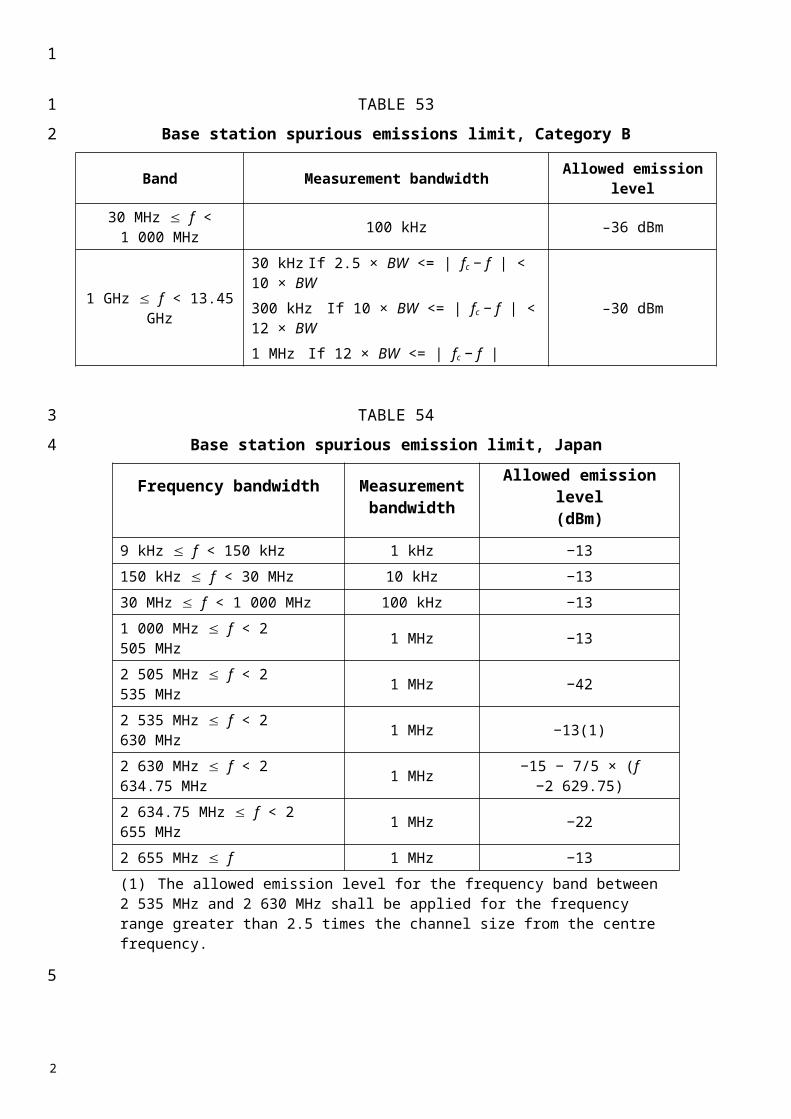
TABLE 1231
General Rreceiver sSpurious eEmission rRequirements
For all frequencies within the mobile station receive and transmit bands, the conducted emissions shall be below the limits in Table 134.
TABLE 1432
Additional Rreceiver sSpurious eEmission rRequirements
Frequency Bband Measurement Bbandwidth
Maximum Llevel(dBm)
Note
30 MHz f < 1 GHz 100 kHz 57 Band Class 6 only
1 GHz f 12.75 GHz 30 kHz –54
With the exception of the frequencies covered by Table 14, for which additional receiver spurious emission requirements applyBand Class 3 only
1 GHz f 12.75 GHz 1 MHz 47
With the exception of the frequencies covered by Table 12, for which additional receiver spurious emission requirements apply
1 GHz f 12.75 GHz 30 kHz –47
With the exception of the frequencies covered by Table 14, for which additional receiver spurious emission requirements applyAll Band Classes except 3 and 6
Frequency bandMeasurement Bbandwidth
(MHz)
Maximum lLevel(dBm)
Note
1 920 f 1 980 MHz 1 –61 Mobile transmit band2 110 f 2 170 MHz 1 –76 Mobile receive band
All Band Classes except 3
1 –81 Mobile receive bandBand Class 3
1
1
2
34
5
6
8
2
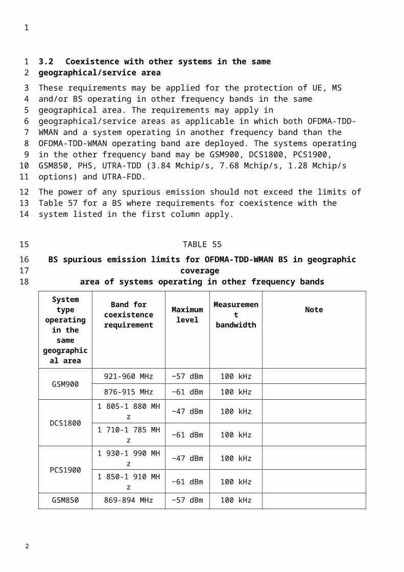
Annex 3
CDMA TDD (UTRA TDD) mobile stations
1 Measurement uncertainty
Values specified in this Annex differ from those specified in Recommendation ITU-R M.1457 since values in this Annex incorporate test tolerances defined in Recommendation ITU-R M.1545.
2 Spectrum mask
2.1 Spectrum mask (3.84 Mchip/s UTRA TDD option)
The spectrum emission mask of the MS applies to frequency offsets (f) between 2.5 and 12.5 MHz on both sides of the carrier frequency.
The out-of-channel emission is specified as a power level relative to the MS output power in a frequency band of 3.84 MHz bandwidth.
The power of any MS emission should not exceed −48.5 dBm/3.84 MHz or the levels specified in Table 13a, whichever is higher.
TABLE 13A
Spectrum emission mask requirement (3.84 Mchip/s TDD option)Δf(1)
(MHz)Minimum requirement Measurement bandwidth
2.5-3.5 −33.5 − 15(1) (f/MHz − 2.5) dBc 30 kHz(2)
3.5-7.5 –33.5 − 1(1) (f/MHz − 3.5) dBc 1 MHz(3)
7.5-8.5 −37.5 − 10(1) (f/MHz − 7.5) dBc 1 MHz(3)
8.5-12.5 −47.5 dBc 1 MHz(3)
(1) f is the separation between the carrier frequency and the centre of the measuring filter.(2) The first and last measurement positions with a 30 kHz filter at f equals 2.515 MHz and 3.485 MHz. (3) The first and last measurement positions with a 1 MHz filter at f equals 4 MHz and 12 MHz. As a general rule, the resolution bandwidth of the measuring equipment should be equal to the measurement bandwidth. To improve measurement accuracy, sensitivity and efficiency, the resolution bandwidth can be different from the measurement bandwidth. When the resolution bandwidth is smaller than the measurement bandwidth, the result should be integrated over the measurement bandwidth in order to obtain the equivalent noise bandwidth of the measurement bandwidth.NOTE 1 – The lower limit should be − 48.550 dBm/3.84 MHz or the minimum requirement presented in this table, whichever is the higher.
2.2 Spectrum mask (1.28 Mchip/s UTRA TDD option)
The spectrum emission mask of the MS applies to frequency offsets between 0.8 and 4.0 MHz on both sides of the carrier frequency.
The out-of-channel emission is specified as a power level relative to the MS output power in a frequency band of 1.6 MHz bandwidth.
dBcHzf 5.3133.55
1
123
4
56
7
8
910
1112
1314
15
16
17
1819
2021
2

TABLE 13B
Spectrum emission mask requirement (1.28 Mchip/s TDD option)Δf(1)
(MHz)Minimum requirement Measurement bandwidth
0.8 −33.5 dBc(3) 30 kHz(2)
0.8-1.8 −33.5 − 14(1)(f/MHz − 0.8) dBc(3) 30 kHz(2)
1.8-2.4 −47.5 − 1725(1)(f/MHz − 1.8) dBc(3) 30 kHz(2)
2.4-4.0 −42.5 dBc(3) 1 MHz(3)
(1) f is the separation between the carrier frequency and the centre of the measuring filter.(2) The first and last measurement positions with a 30 kHz filter at f equals to 0.815 MHz and 2.385 MHz.(3) The first and last measurement positions with a 1 MHz filter at f equals 2.9 MHz and 3.5 MHz. As a general
rule, the resolution bandwidth of the measuring equipment should be equal to the measurement bandwidth. To improve measurement accuracy, sensitivity and efficiency, the resolution bandwidth can be different from the measurement bandwidth. When the resolution bandwidth is smaller than the measurement bandwidth, the result should be integrated over the measurement bandwidth in order to obtain the equivalent noise bandwidth of the measurement bandwidth.
NOTE 1 – The lower limit should be −53.5 dBm/1.28 MHz or the minimum requirement presented in this table, whichever is the higher.
2.3 Spectrum mask (7.68 Mchip/s UTRA TDD option)
The spectrum emission mask of the UE applies to frequencies which are between 5 MHz and 25 MHz from the UE centre carrier frequency. The out-of-channel emission is specified relative to the RRC filtered mean power of the UE carrier.
The power of any UE emission should not exceed the levels specified in Table 13c.
TABLE 13C
Spectrum emission mask requirement (7.68 Mchip/s TDD option)Δf(1)
(MHz)Minimum requirement Measurement bandwidth
5.0-5.75 30 kHz(2)
5.75-7.0 30 kHz(2)
7.0-15 1 MHz(3)
15.0-17.0 1 MHz(3)
17.0-25.0 −51.5 dBc 1 MHz(3)
(1) f is the separation between the carrier frequency and the centre of the measuring filter.(2) The first and last measurement positions with a 30 kHz filter at f equals 5.015 MHz and 6.985 MHz.(3) The first and last measurement positions with a 1 MHz filter at f equals 7.5 MHz and 24.5 MHz. As a general
rule, the resolution bandwidth of the measuring equipment should be equal to the measurement bandwidth. To improve measurement accuracy, sensitivity and efficiency, the resolution bandwidth can be different from the measurement bandwidth. When the resolution bandwidth is smaller than the measurement bandwidth, the result should be integrated over the measurement bandwidth in order to obtain the equivalent noise bandwidth of the measurement bandwidth.
NOTE 1 – The lower limit should be −47 dBm/7.68 MHz or the minimum requirement presented in this table, whichever is the higher.
1
1
2
3
456
7
8
9
2
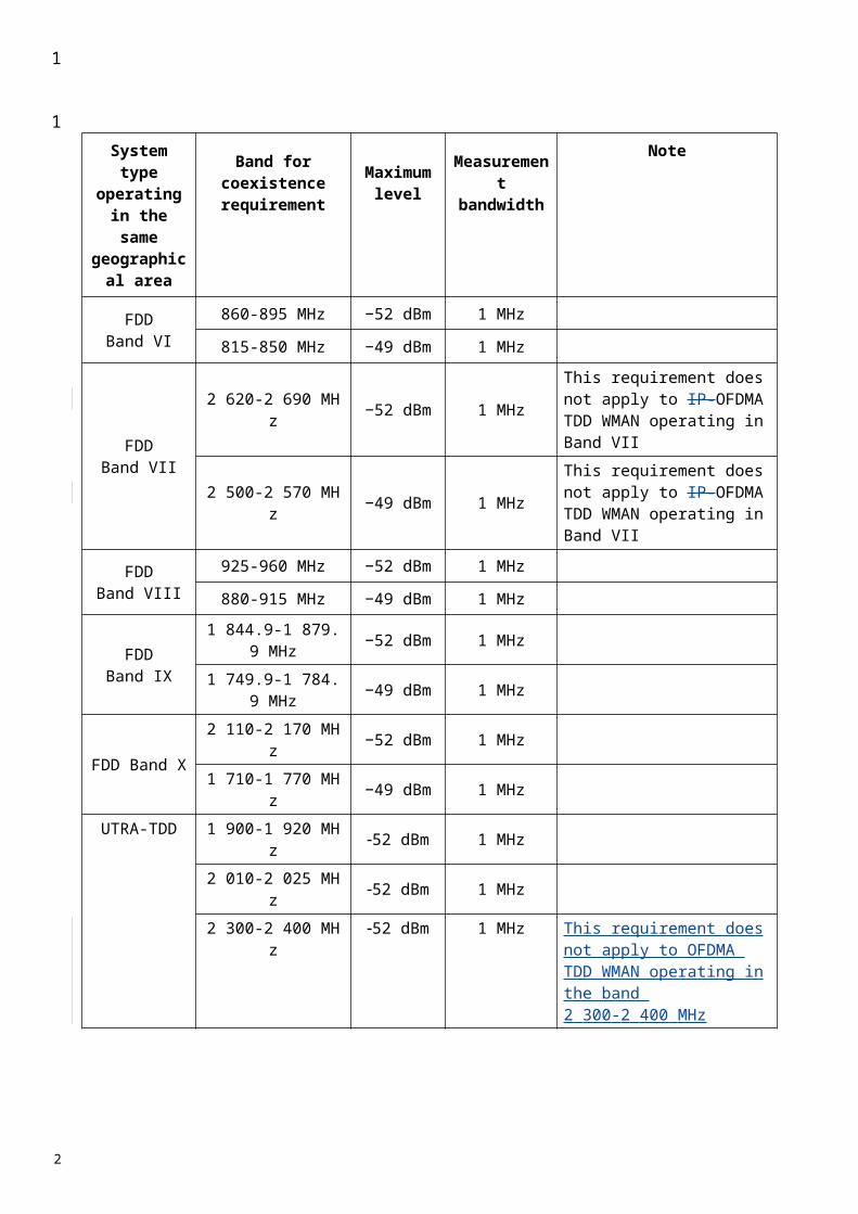
2.4 E-UTRA spectrum mask
The output UE transmitter spectrum consists of the three components; the emission within the occupied bandwidth (channel bandwidth), the Out Of Band (OOB) emissions and the far out spurious emission domain (Figure 3).
FIGURE 3
The spectrum emission mask of the MS applies to frequencies (ΔfOOB) starting from the ± edges of the assigned E-UTRA channel bandwidth. For frequencies greater than (ΔfOOB) as specified in Table 13d the spurious requirements in §4 are applicable.
2.4.1 General E-UTRA spectrum mask
The power of any MS emission shall not exceed the levels specified in Table 13d for the specified channel bandwidths.
TABLE 13d
General E-UTRA spectrum emission maskΔfOOB
(MHz)Spectrum emission limit (dBm)/ Channel bandwidth 1.4MHz
3MHz
5MHz
10MHz
15MHz
20MHz
Measurement bandwidth
0-1 -13.5 -16.5 -18.5 -19.5 30 kHz 1-2.5 -8.5 -8.5 -8.5 -8.5 1 MHz 2.5-2.8 -8.5 -8.5 -8.5 -8.5 1 MHz 2.8-5 -8.5 -8.5 -8.5 -8.5 1 MHz 5-6 -11.5 -11.5 -11.5 -11.5 1 MHz 6-10 -23.5 -11.5 -11.5 -11.5 1 MHz 10-15 -23.5 -11.5 -11.5 1 MHz 15-20 -23.5 -11.5 1 MHz 20-25 -23.5 1 MHz
Note- the values for 1.4 MHz and 3.0 MHz channel bandwidths will be addressed at a later stage
1
1
234
5
67
89
10
11
1213
14
15
1617
2

NOTE – As a general rule, the resolution bandwidth of the measuring equipment should be equal to the measurement bandwidth. However, to improve measurement accuracy, sensitivity and efficiency, the resolution bandwidth may be smaller than the measurement bandwidth. When the resolution bandwidth is smaller than the measurement bandwidth, the result should be integrated over the measurement bandwidth in order to obtain the equivalent noise bandwidth of the measurement bandwidth.
3 ACLR
3.1 ACLR for UTRA
ACLR is the ratio of the transmitted power to the power measured after a receiver filter in the adjacent channel(s). Both the transmitted power and the received power are measured through a matched filter (root raised cosine and roll-off 0.22) with a noise power bandwidth equal to the chip rate. The requirements should apply whatever the type of transmitter considered (single carrier or multi-carrier). It applies for all transmission modes foreseen by the manufacturer’s specification. The limit for ACLR should be as specified in Table 14a-14c).
TABLE 14
Table 14a) MS ACLR limits for 3.84 Mchip/s TDD option
Power class Adjacent channel ACLR limit(dB)
2, 3 MS channel ± 5 MHz 32.22, 3 MS channel ± 10 MHz 42.2
Table 14b) MS ACLR limits for 1.28 Mchip/s TDD option
Power class Adjacent channel ACLR limit(dB)
2, 3 MS channel ± 1.6 MHz 32.22, 3 MS channel ± 3.2 MHz 42.2
Table 14c) MS ACLR limits for 7.68 Mchip/s TDD option
Power classAdjacent channel
Chip rate for RRCmeasurement filter
(MHz)
ACLR limit(dB)
2, 3 MS channel ± 7.5 MHz 3.84 32.22, 3 MS channel ± 12.5 MHz 3.84 42.22, 3 MS channel ± 10.0 MHz 7.68 32.22, 3 MS channel ± 20.0 MHz 7.68 42.2
1
123456
7
8
91011121314
15
16
17
1819
2021
2
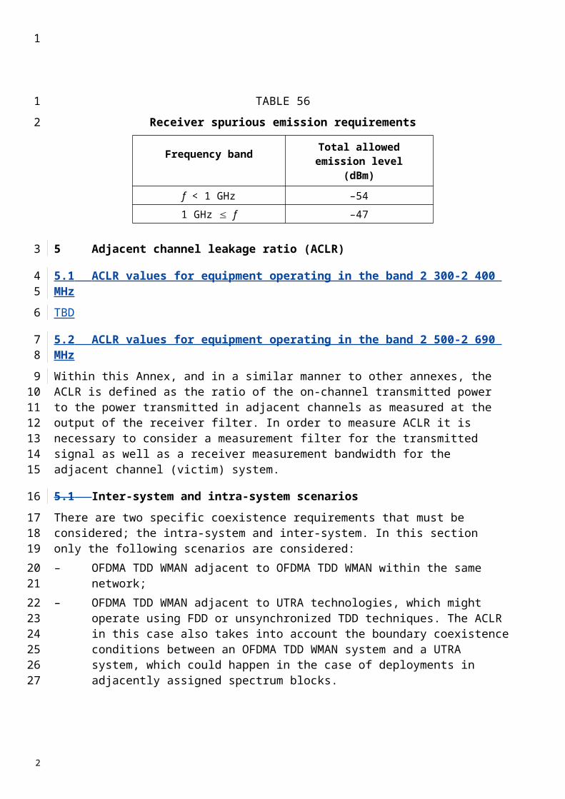
3.2 ACLR for E-UTRA
ACLR is the ratio of the filtered mean power centred on the assigned channel frequency to the filtered mean power centred on an adjacent channel frequency. The ACLR requirements are specified for two scenarios: for (an) adjacent E -UTRA and/or UTRA channels (Figure 4).
FIGURE 4
E-UTRAACLR1 UTRA ACLR2 UTRAACLR1
RB
E-UTRA channel
Channel
ΔfOOB
3.2.1 Limits for E-UTRA
E-UTRA Adjacent Channel Leakage power Ratio (E-UTRAACLR) is the ratio of the filtered mean power centred on the assigned channel frequency to the filtered mean power centred on an adjacent channel frequency. The E-UTRA on channel and adjacent channel power is measured with a rectangular measurement bandwidth filter. The limits should be as specified in Table 14D.
TABLE 14D
General requirements for E-UTRAACLR
Channel bandwidth / E-UTRAACLR1 / measurement bandwidth
1.4MHz
3MHz
5MHz
10MHz
15MHz
20MHz
E-UTRAACLR1 -29.2 dB -29.2 dB -29.2 dB -29.2 dB -29.2 dB -29.2 dB
E-UTRA channel Measurement bandwidth
4.5 MHz 9.0 MHz 13.5 MHz 18 MHz
UE channel +5MHz or
-5MHz
+10MHz or
-10MHz
+15MHz or
-15MHz
+20MHz or
-20MHz
3.2.2 Limits for E-UTRA for UTRA co-existence in the same geographical area
For adjacent UTRA carriers the limits should be as specified in Table 14e.
UTRA Adjacent Channel Leakage power Ratio (UTRAACLR) is the ratio of the filtered mean power centred on the assigned E-UTRA channel frequency to the filtered mean power centred on an adjacent(s) UTRA channel frequency.
1
1
234
5
67
89
1011
12
13
14
15
16
171819
2
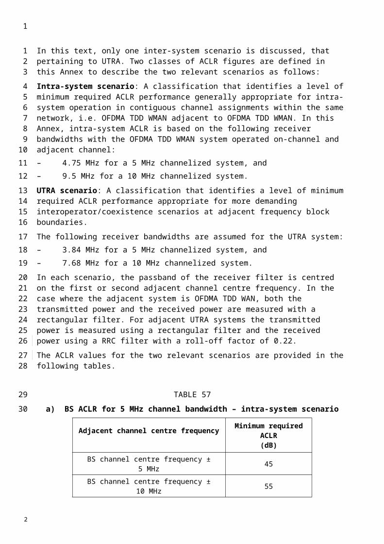
UTRA Adjacent Channel Leakage power Ratio is specified for both the first UTRA 5 MHz adjacent channel (UTRAACLR1) and the 2nd UTRA 5MHz adjacent channel (UTRAACLR2) .The UTRA channel is measured with a 3.84 MHz RRC bandwidth filter with roll-off factor =0.22. The E-UTRA channel is measured with a rectangular measurement bandwidth filter.
TABLE 14E
Additional requirements
Channel bandwidth / UTRAACLR1/2 / measurement bandwidth
1.4MHz
3MHz
5MHz
10MHz
15MHz
20MHz
UTRAACLR1 32.2 dB 32.2 dB 32.2 dB 32.2 dB 32.2 dB 32.2 dB
UTRAACLR2 - - 35.2 dB 35.2 dB 35.2 dB 35.2 dB
E-UTRA channel Measurement bandwidth
- 4.5 MHz 9.0 MHz 13.5 MHz 18 MHz
UTRA channel Measurement bandwidth
- - 3.84 MHz 3.84 MHz 3.84 MHz 3.84 MHz
UE channel for UTRAACLR1
+2.5MHz from upper band edge or -2.5MHz from lower band edge
UE channel for UTRAACLR2
+7.5MHz from upper band edge or -7.5MHz from lower band edge
3.2.3 Additional ACLR limits
Additional ACLR requirements are signalled by the network to indicate that the UE shall meet an additional requirement for a specific deployment scenario as part of the cell handover/broadcast message.
The additional ACLR limits are specified for the 2nd UTRA adjacent channel (UTRAACLR2). .The UTRA channel is measured with a 3.84 MHz RRC bandwidth filter with roll-off factor =0.22. The E-UTRA channel is measured with a rectangular measurement bandwidth filter.
1
1234
5
6
7
8
91011
121314
2
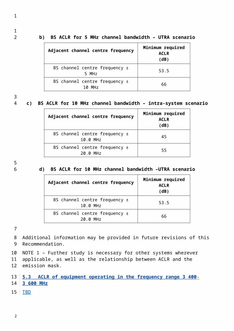
TABLE 14F
Additional requirements (UTRAACLR2)
Channel bandwidth / UTRAACLR2 / measurement bandwidth
1.4MHz
3MHz
5MHz
10MHz
15MHz
20MHz
UTRAACLR2bis - - 42.2 dB 42.2 dB - -
E-UTRA channel Measurement bandwidth
- - 4.5 MHz 9.0 MHz - -
UTRA channel Measurement bandwidth
- - 3.84 MHz 3.84 MHz - -
UE channel for UTRAACLR2bis +7.5MHz from upper band edge or -7.5MHz from lower band edge
4 Transmitter spurious emissions (conducted)
4.1 Transmitter spurious emissions for UTRA
For UTRA, Tthe spurious emissions should be less than the limits specified in Tables 15, 16a), 16b) and 16c). The following requirements are only applicable for MS centre carrier frequency offsets greater than 12.5 MHz (3.84 Mchip/s TDD option), 4 MHz (1.28 Mchip/s TDD option) or 25 MHz (7.68 Mchip/s TDD option).
TABLE 15
General spurious emissions requirements for UTRA
Frequency band Measurement bandwidth Minimum requirement(dBm)
9 kHz f 150 kHz 1 kHz –36150 kHz f 30 MHz 10 kHz –3630 MHz f 1 000 MHz 100 kHz –36
1 GHz f 12.75 GHz 1 MHz –30
1
1
2
3
4
5678
9
10
11
2
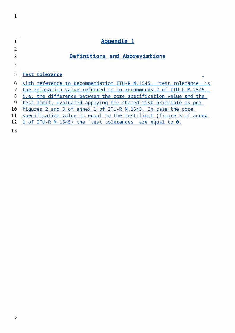
TABLE 16
a) Additional spurious emissions requirements (3.84 Mchip/s TDD option)
Frequency bandwidth Measurement bandwidth Minimum requirement(dBm)
921 MHz f < 925 MHz 100 kHz −60 (Note 1)925 MHz f 935 MHz 100 kHz −67 (Note 1)935 MHz < f 960 MHz 100 kHz −79 (Note 1)
1 805 MHz f 1 880 MHz 100 kHz −71 (Note 1) 2 620 MHz f 2 690 MHz 3.84 MHz −37 (Note 1)
1 884.5 MHz f 1 919.6 MHz 300 kHz −41 (Note 2)NOTE 1 – The measurements are made on frequencies which are integer multiples of 200 kHz. As exceptions, up to five measurements with a level up to the applicable requirements defined in Table 15 are permitted for each absolute RF channel used in the measurement. NOTE 2 – Applicable for transmission in 2 010-2 025 MHz.
b) Additional spurious emissions requirements (1.28 Mchips TDD option)Operating Band Frequency Bandwidth Measurement
BandwidthMinimum
requirementa 921 MHz f < 925 MHz 100 kHz -60 dBm (note1)
925 MHz f 935 MHz 100 kHz -67 dBm (note1)935 MHz < f 960 MHz 100 kHz -79 dBm (note1)
1805 MHz f 1880 MHz 100 kHz -71 dBm (note1)2010 MHz f 2025 MHz 1MHz -65 dBm (Note2)1900 MHz f 1920 MHz 1MHz -65 dBm (Note 3)
b 1850 MHz f 1910 MHz 1 MHz -65 dBm (Note 4)1930 MHz f 1990 MHz 1 MHz -65 dBm (Note 5)2010 MHz f 2025 MHz 1MHz -65 dBm
c 2010 MHz f 2025 MHz 1 MHz -65 dBmd 1900 MHz f 1920 MHz 1 MHz -65 dBm
2010 MHz f 2025 MHz 1 MHz -65 dBm2620 MHz f 2690 MHz 3.84 MHz -37 dBm
e 921 MHz f < 925 MHz 100 kHz -60 dBm (note1)925 MHz f 935 MHz 100 kHz -67 dBm (note1)935 MHz < f 960 MHz 100 kHz -79 dBm (note1)
1805 MHz f 1880 MHz 100 kHz -71 dBm (note1)1900 MHz f 1920 MHz 1 MHz -65 dBm2010 MHz f 2025 MHz 1 MHz -65 dBm
NOTE 1 –The measurements are made on frequencies which are integer multiples of 200 kHz. As exceptions, up to five measurements with a level up to the applicable requirements defined in Table 6.7c are permitted for each UARFCN used in the measurement.NOTE 2 – This requirement is only applicable when UE operating in 1900-1920MHz of band a.NOTE 3 – This requirement is only applicable when UE operating in 2010-2025MHz of band a.NOTE 4 – This requirement is only applicable when UE operating in 1930-1990MHz of band b.NOTE 5 – This requirement is only applicable when UE operating in 1850-1910MHz of band b.
1
1
2
34
5
2
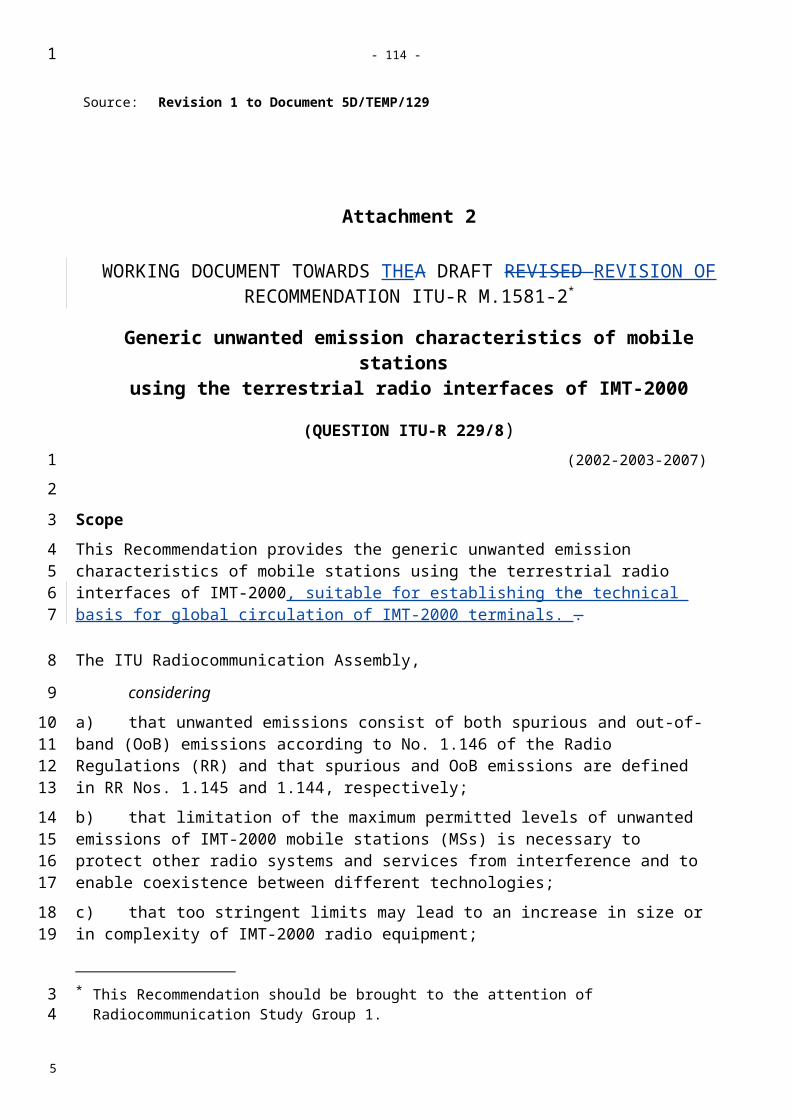
Frequency bandwidth Measurement bandwidth Minimum requirement(dBm)
921 MHz f < 925 MHz 100 kHz −60 (Note 1) 925 MHz f 935 MHz 100 kHz −67 (Note 1) 935 MHz < f 960 MHz 100 kHz −79 (Note 1) 1 805 MHz f 1 880 MHz 100 kHz −71 (Note 1) 2 620 MHz f 2 690 MHz 3.84 MHz −37 (Note 1)
NOTE 1 – The measurements are made on frequencies which are integer multiples of 200 kHz. As exceptions, up to five measurements with a level up to the applicable requirements defined in Table 15 are permitted for each absolute RF channel used in the measurement.
c) Additional spurious emissions requirements (7.68 Mchips TDD option)
Frequency bandwidth Measurement bandwidth Minimum requirement(dBm)
921 MHz f < 925 MHz 100 kHz −60 (Note 1)925 MHz f 935 MHz 100 kHz −67 (Note 1)935 MHz < f 960 MHz 100 kHz −79 (Note 1)
1 805 MHz f 1 880 MHz 100 kHz −71 (Note 1)2 620 MHz f 2 690 MHz 3.84 MHz −37 (Note 1)
1 884.5 MHz f 1 919.6 MHz 300 kHz −41 (Note 2)
NOTE 1 – The measurements are made on frequencies which are integer multiples of 200 kHz. As exceptions, up to five measurements with a level up to the applicable requirements defined in Table 15 are permitted for each absolute RF channel used in the measurement. NOTE 2 – Applicable for transmission in 2 010-2 025 MHz.
4.2 Transmitter spurious emissions for E-UTRA
For E-UTRA, the spurious emission limits apply for frequency ranges that are more than ΔfOOB (MHz) from the edge of the channel bandwidth (Table 16d).
TABLE 16d
Boundary between E-UTRA ΔfOOB and spurious emission domain
Channel bandwidth
1.4MHz
3.0MHz
5MHz
10MHz
15MHz
20MHz
ΔfOOB (MHz) 10 15 20 25
Note- the values for 1.4 MHz and 3.0 MHz channel bandwidths will be addressed at a later stage
The spurious emission limits in Table 16e apply for all E-UTRA transmitter band configurations and channel bandwidths.
1
1
2
3
4
56
7
8
910
11
1213
14
2
TABLE 16E
General spurious emissions requirements for E-UTRA
Frequency band Measurement bandwidth Minimum requirement(dBm)
9 kHz f 150 kHz 1 kHz –36 150 kHz f 30 MHz 10 kHz –36 30 MHz f 1 000 MHz 100 kHz –36 1 GHz f 12.75 GHz 1 MHz –30
TABLE 16F
Spurious emissions requirements for UE co-existance in E-UTRA bands
E-UTRA Band
Spurious emission Protected band Frequency range
(MHz)Level (dBm)
Bandwidth (MHz)
Comment
33 E-UTRA Band 1, 3, 8, 34, 38, 39, 40 FDL_low - FDL_high -50 1 Note 5 34 E-UTRA Band 1, 3, 7, 8, 9, 11, 33, 38,39,
40 FDL_low - FDL_high -50 1 Note 5 Frequency range 860 - 895 -50 1Frequency range 1884.5 - 1919.6 -41 0.3
353637 - 38 E-UTRA Band 1,3, 33, 34 FDL_low - FDL_high -50 1 39 E-UTRA Band 34, 40 FDL_low - FDL_high -50 1 40 E-UTRA Band 1, 3, 33, 34, 39 FDL_low - FDL_high -50 1
Note 1 FDL_low and FDL_high refer to each E-UTRA frequency band specified in Note 3 of the Scope
2 A number of exceptions are permitted and is FFS. These exceptions include both spurious due to LO mixing and I/Q imbalance for specific values of NRB. For these exceptions the requirements of Table 16e are applicable.
3 To meet these requirements some restriction will be needed for either the operating band or protected band
4 Requirements are specified in terms of E-UTRA sub-bands
5 For non synchronised TDD operation to meet these requirements some restriction will be needed for either the operating band or protected band
5 Receiver spurious emissions (conducted)
5.1 Receiver spurious emissions for UTRA
For UTRA, The the power of any spurious emissions from the receiver should not exceed the limits given in Tables 17, 18a), 18b) and 18c).
TABLE 17
General receiver spurious emission requirements
1
1
2
3
4
5
6
7
89
10
11
2
TABLE 18
a) Receiver spurious emission requirements (3.84 Mchip/s UTRA TDD option)
Band Maximum level
Measurement bandwidth Note
30 MHz-1 GHz −57 dBm 100 kHz1 GHz-1.9 GHz and
1.92 GHz-2.01 GHz and2.025 GHz-2.11 GHz and
2.17 GHz- 2.57 GHz
−47 dBm 1 MHz
With the exception of frequencies between 12.5 MHz below the first carrier frequency and 12.5 MHz above the last carrier frequency used by the MS.
1.9 GHz-1.92 GHz and2.01 GHz-2.025 GHz and2.11 GHz-2.170 GHz and
2.57 GHz-2.69 GHz
−60 dBm 3.84 MHz
With the exception of frequencies between 12.5 MHz below the first carrier frequency and 12.5 MHz above the last carrier frequency used by the MS.
2.69 GHz-12.75 GHz −47 dBm 1 MHz
b) Receiver spurious emission requirements (1.28 Mchip/s UTRA TDD option)
Band Maximum level
Measurement bandwidth Note
30 MHz-1 GHz −57 dBm 100 kHz1 GHz-1.9 GHz and
1.92 GHz-2.01 GHz and2.025 GHz-2.11 GHz and2.17 GHz-2.30 GHz and
2.40 GHz - 2.57 GHz
−47 dBm 1 MHz
With the exception of frequencies between 4 MHz below the first carrier frequency and 4 MHz above the last carrier frequency used by the MS.
1.9 GHz-1.92 GHz and2.01 GHz-2.025 GHz and2.11 GHz-2.170 GHz and2.30 GHz-2.40 GHz and
2.57 GHz-2.69 GHz
−64 dBm 1.28 MHz
With the exception of frequencies between 4 MHz below the first carrier frequency and 4 MHz above the last carrier frequency used by the MS.
2.69 GHz 12.75 GHz −47 dBm 1 MHz
Frequency band Measurement bandwidth
Maximum level
(dBm)Note
30 MHz f 1 GHz 100 kHz –571 GHz f 12.75 GHz 1 MHz –47 With the exception of the frequencies
covered by Tables 18a), 18b) and 18c), for which additional receiver spurious emission requirements apply.
1
2
3
45
6
2
TABLE 18 (end)
c) Receiver spurious emission requirements (7.68 Mchip/s UTRA TDD option)
Band Maximum level
Measurement bandwidth Note
30 MHz-1 GHz −57 dBm 100 kHz1 GHz-1.9 GHz and
1.92 GHz-2.01 GHz and2.025 GHz-2.11 GHz and
2.17 GHz-2.57 GHz
−47 dBm 1 MHz
With the exception of frequencies between 25 MHz below the first carrier frequency and 25 MHz above the last carrier frequency used by the MS.
1.9 GHz-1.92 GHz and2.01 GHz-2.025 GHz and2.11 GHz-2.170 GHz and
2.57 GHz-2.69 GHz
−57 dBm 7.68 MHz
With the exception of frequencies between 25 MHz below the first carrier frequency and 25 MHz above the last carrier frequency used by the MS.
2.69 GHz-12.75 GHz −47 dBm 1 MHz
5.2 Receiver spurious emissions for E-UTRA
The power of any narrow band CW spurious emission shall not exceed the maximum level specified in Table 19.
TABLE 19
General receiver spurious emission requirements for E-UTRAFrequency Band Measurement
BandwidthMaximum
levelNote
30MHz f < 1GHz 100 kHz -57 dBm1GHz f 12.75 GHz 1 MHz -47 dBm
1
1
2
3
45
6
7
8
2

Annex 4
TDMA Single-Carrier (UWC-136) mobile stations
Part A
Conformance requirements (30 kHz)
1 Spectrum mask
Spectrum noise suppression is the restraint of sideband energy outside the active transmit channel. This RF spectrum is the result of power ramping, modulation and all sources of noise. The spectrum is primarily the result of events that do not occur at the same time: digital modulation and power ramping (switching transients). The RF spectrum from these two events are specified separately.
Adjacent and first or second alternate channel power is that part of the mean power output of the transmitter resulting from the modulation and noise which falls within a specified passband centred on either of the adjacent or first or second alternate channels.
The emission power should not exceed the limits specified in Table 19.
TABLE 19
Adjacent and alternate channel power requirements
OoB power arising from switching transients is the peak power of the spectrum, arising from the ramping-on and ramping-off of the transmitter, that fall within defined frequency bands outside the active transmit channel.
The peak emission power should not exceed the limits specified in Table 20.
Channel Maximum level
In either adjacent channel, centred 30 kHz from the centre frequency
26 dB below the mean output power
In either alternate channel, centred 60 kHz from the centre frequency
45 dB below the mean output power
In either second alternate channel centred 90 kHz from the centre frequency
45 dB below the mean output power or –13 dBm measured in 30 kHz bandwidth, whichever is the lower power
1
123
4
5
6
7
8
9101112
131415
16
17
18
20
212223
24
25
2
TABLE 20
Switching transients requirements
2 Transmitter spurious emissions (conducted)
The power of any spurious emission should not exceed the limits specified in Table 21.
TABLE 21
MS spurious emission limits
2.1 Coexistence with services in adjacent frequency bands
This requirement provides for the protection of receivers operating in bands adjacent to the MS transmit frequency band of 1 920 to 1 980 MHz: GSM 900, R-GSM and UTRA TDD.NOTE 1 – UTRA FDD operates in the same frequency band as UWC-136.
The power of any spurious emission should not exceed the limits specified in Table 22.
Channel Maximum level
In either adjacent channel, centred 30 kHz from the centre frequency
26 dB below the peak output power reference
In either alternate channel, centred 60 kHz from the centre frequency
45 dB below the peak output power reference
In either second alternate channel centred 90 kHz from the centre frequency
45 dB below the peak output power reference or –13 dBm measured in 30 kHz bandwidth, whichever is the lower power
Band ( f ) (1) Maximum level(dBm)
Measurement bandwidth Note
9 kHz f 150 kHz –36 1 kHz (2)
150 kHz f 30 MHz –36 10 kHz (2)
30 MHz f 1 000 MHz –36 100 kHz (2)
1 000 MHz f 1 920 MHz –30 1 MHz (2)
1 920 MHz f 1 980 MHz –30 30 kHz (3)
1 980 MHz f 2 110 MHz –30 1 MHz (2)
2 110 MHz f 2 170 MHz –70 30 kHz (4)
2 170 MHz f 12.75 GHz –30 1 MHz (2)
(1) f is the frequency of the spurious emission.(2) In accordance with the applicable clauses of Recommendation ITU-R SM.329.(3) MS transmit band.(4) MS receive band.
1
1
2
4
5
6
7
8
10
111213
14
2
TABLE 22
Additional spurious emissions requirements
3 Receiver spurious emissions (idle mode)
The power of any spurious emissions should not exceed the limits given in Table 23.
TABLE 23
General receiver spurious emission requirements
Service Frequency bandMeasurement
bandwidth(kHz)
Limit(dBm)
R-GSM 921 f 925 MHz 100 –60R-GSM 925 f 935 MHz 100 –67
GSM 900/R-GSM 935 f 960 MHz 100 –79DCS 1800 1 805 f 1 880 MHz 100 –71
UTRA TDD 1 900 f 1 920 MHz 100 –62UTRA TDD 2 010 f 2 025 MHz 100 –62
NOTE 1 – The measurements are made on frequencies which are integer multiples of 200 kHz. Up to five exceptions of up to –36 dBm are permitted in the GSM 900, DCS 1800 and UTRA bands, and up to three exceptions of up to –36 dBm are permitted in the GSM 400 bands.
Frequency band Measurement bandwidth
Maximum level
(dBm)Note
30 MHz f 1 GHz 100 kHz –571 GHz f 12.75 GHz 1 MHz – 47 With the exception of the frequencies
covered by the table below, for which additional receiver spurious emission requirements apply(1)
(1) (Editorial Note) – In TFES Harmonized Standard v1.0.2, no additional receiver spurious emission is specified; yet, it is expected that there will be a table added, in the same form as for the other technologies (see Tables 5, 12 and 18).
1
1
2
4
5
6
7
9
10
11
12
2
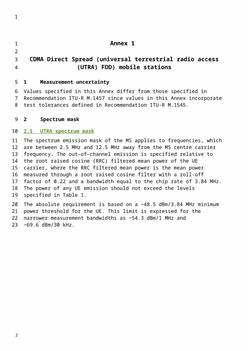
PART B
Conformance requirements (200 kHz)
The 200 kHz channel provides packet data service and employs both 8-level phase shift keying (8-PSK) and Gaussian minimum shift keying (GMSK) modulations.
1 Spectrum mask
Output RF spectrum is the relationship between the frequency offset from the carrier and the power, measured in a specified bandwidth and time, produced by the MS due to the effects of modulation and power ramping.
The specifications contained in this subclause apply in frequency hopping as well as in non-frequency hopping modes.
Due to the bursty nature of the signal, the output RF spectrum results from two effects: the modulation process, and the power ramping up and down (switching transients).– The level of the output RF spectrum due to GMSK and 8-PSK modulations should be no
more than that given in Tables 24 and 25.– The level of the output RF spectrum due to switching transients should be no more than that
given in Table 26.– The power emitted should not exceed –71 dBm in frequency band 2 110-2 170 MHz.
2 Spectrum due to the modulation and wideband noise
The output RF modulation spectrum is specified in Tables 24 and 25. This specification applies for all RF channels supported by the equipment.
The specification applies to the entire relevant transmit band and up to 2 MHz either side.
The limits should be met under the following measurement conditions:– Zero frequency scan, filter bandwidth and video bandwidth of 30 kHz up to 1 800 kHz from
the carrier and 100 kHz at 1 800 kHz and above from the carrier, with averaging done over 50% to 90% of the useful part of the transmitted bursts, excluding the midamble, and then averaged over at least 200 such burst measurements. Above 1 800 kHz from the carrier, only measurements centred on 200 kHz multiples are taken with averaging over 50 bursts.
– When tests are done in frequency hopping mode, the averaging should include only bursts transmitted when the hopping carrier corresponds to the nominal carrier of the measurement. The limits then apply to the measurement results for any of the hopping frequencies.
The figures in Table 24, at the vertically listed power level (dBm) and at the horizontally listed frequency offset from the carrier (kHz), are then the maximum allowed level (dB) relative to a measurement in 30 kHz on the carrier.NOTE 1 – This approach of specification has been chosen for convenience and speed of testing. It does however require careful interpretation if there is a need to convert figures in the following tables into spectral density values, in that only part of the power of the carrier is used as the relative reference, and in addition different measurement bandwidths are applied at different offsets from the carrier.
1
1
2
34
5
678
910
11121314151617
18
1920
21
22232425262728293031
3233343536373839
2
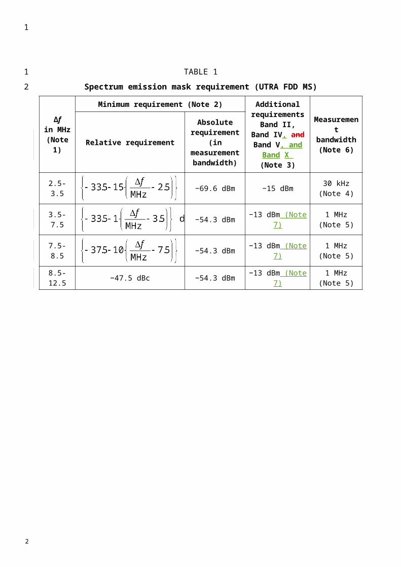
TABLE 24
Relative maximum level due to modulation
The following exceptions should apply, using the same measurement conditions as specified above:– In the combined range of 600 kHz to 6 MHz above and below the carrier, in up to three
bands of 200 kHz width centred on a frequency which is an integer multiple of 200 kHz, exception levels of up to –36 dBm are allowed.
– Above 6 MHz offset from the carrier in up to 12 bands of 200 kHz width centred on a frequency which is an integer multiple of 200 kHz, exception levels of up to –36 dBm are allowed.
Using the same measurement conditions as specified above, if a requirement in Table 24 results in lower than the power limit given in Table 25, then the latter should be applied instead.
TABLE 25
Absolute maximum level due to modulation
3 Spectrum due to switching transients
These effects are also measured in the time domain and the specifications assume the following measurement conditions: zero frequency scan, filter bandwidth 30 kHz, peak hold, and video bandwidth 100 kHz. Table 26 specifies the limits.
Carrier power (dBm)
Frequency offset(kHz)
100 200 250 400 6001 200
1 2001 800
1 800
6 000
6 000
33 0.5 –30 –33 –60 –60 –60 –68 –7632 0.5 –30 –33 –60 –60 –60 –67 –7530 0.5 –30 –33 –60 –60(1) –60 –65 –7328 0.5 –30 –33 –60 –60(1) –60 –63 –7126 0.5 –30 –33 –60 –60(1) –60 –61 –69
24 0.5 –30 –33 –60 –60(1) –60 –59 –67(1) For equipment supporting 8-PSK, the requirement for 8-PSK modulation is –54 dB.
Frequency offset from the carrier(kHz)
Level(dBm)
600 –36 600, 1 800 –56
1 800 –51
1
1
2
4
56789
1011
1213
14
15
17
18
192021
2
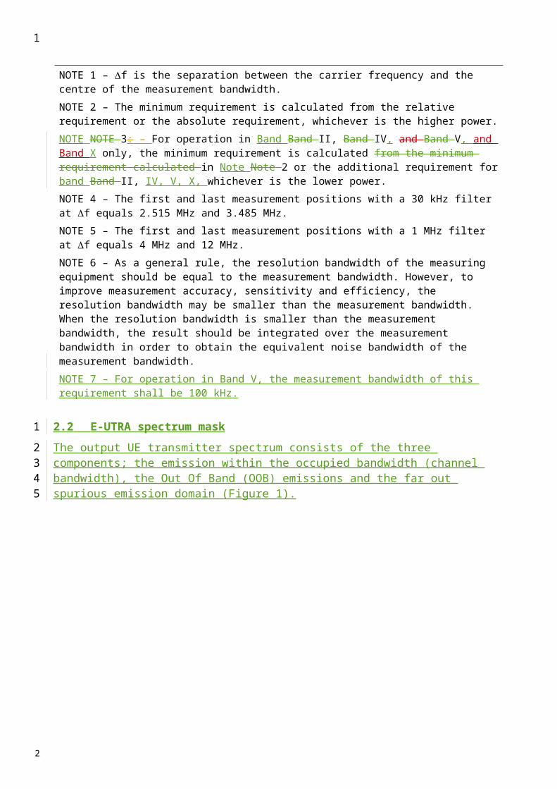
TABLE 26
Maximum levels due to switching transients
NOTE 1 – The relaxation for carrier power level 39 dBm is in line with the modulated spectra and thus causes negligible additional interference to an analogue system by an UWC-136 200 kHz signal.NOTE 2 – The near-far dynamics with this specification has been estimated to be approximately 58 dB for MS operating at a power level of 8 W or 49 dB for MSs operating at a power level of 1 W. The near-far dynamics then gradually decreases by 2 dB per power level down to 32 dB for MSs operating in cells with a maximum allowed output power of 20 mW or 29 dB for MS operating at 10 mW.NOTE 3 – The possible performance degradation due to switching transient leaking into the beginning or the end of a burst, was estimated and found to be acceptable with respect to the BER due to co-channel interference (C/I).
4 Transmitter spurious emissions (conducted)
The power of any spurious emission should not exceed the limits specified in Table 27.
TABLE 27
MS spurious emission limits
Carrier power level(dBm)
Maximum level measured at various frequency offsets
400 kHz 600 kHz 1 200 kHz 1 800 kHz39 –21 dBm –26 dBm –32 dBm –36 dBm
37 –23 dBm –26 dBm –32 dBm –36 dBm
Band ( f )(1) Measurement bandwidth
Maximum level(dBm) Note
9 kHz f 150 kHz 1 kHz –36 (2)
150 kHz f 30 MHz 10 kHz –36 (2)
30 MHz f 1 000 MHz 100 kHz –36 (2)
1 000 MHz f 1 920 MHz 1 MHz –30 (2)
1 920 MHz f 1 980 MHz 100 kHz –36 (3)
1 980 MHz f 2 110 MHz 1 MHz –30 (2)
2 110 MHz f 2 170 MHz 100 kHz –66 (4)
2 170 MHz f 12.75 GHz 1 MHz –30 (2)
(1) f is the frequency of the spurious emission.(2) In accordance with the applicable clauses of Recommendation ITU-R SM.329.(3) MS transmit band.(4) MS receive band.
1
1
2
3
56789
1011121314
15
16
17
18
2

5 Coexistence with services in adjacent frequency bands
This requirement provides for the protection of receivers operating in bands adjacent to the MS transmit frequency band of 1 920 MHz to 1 980 MHz: GSM 900, R-GSM, UTRA TDD.
The power of any spurious emission should not exceed the limits specified in Table 28.
TABLE 28
Additional spurious emissions requirements
6 Receiver spurious emissions (idle mode)
The power of any spurious emissions should not exceed the limits given in Table 29.
TABLE 29
General receiver spurious emission requirements
Service Frequency bandMeasurement
bandwidth(kHz)
Minimum requirement(dBm)
R-GSM 921 f 925 MHz 100 –60R-GSM 925 f 935 MHz 100 –67
GSM 900/R-GSM 935 f 960 MHz 100 –79DCS 1800 1 805 f 1 880 MHz 100 –71
UTRA TDD 1 900 f 1 920 MHz 100 –62UTRA TDD 2 010 f 2 025 MHz 100 –62
NOTE 1 – The measurements are made on frequencies which are integer multiples of 200 kHz. Up to five exceptions of up to –36 dBm are permitted in the GSM 900, DCS 1800 and UTRA bands, and up to three exceptions of up to –36 dBm are permitted in the GSM 400 bands.
Frequency bandMeasurement
bandwidthMaximum
level(dBm)
Note
30 MHz f 1 GHz 100 kHz –571 GHz f 12.75 GHz 1 MHz –47 With the exception of the frequencies
covered by the table below, for which additional receiver spurious emission requirements apply(1)
(1) (Editorial Note) – In TFES Harmonized Standard v1.0.2, no additional receiver spurious emission is specified; yet, it is expected that there will be a table added, in the same form as for the other technologies (see Tables 5, 12 and 18).
1
1
2
34
5
6
7
8
10
11
12
13
14
2

Annex 5
FDMA/TDMA (digital enhanced cordless telecommunications(DECT)) mobile stations
1 Spectrum mask
If the equipment under test (EUT) is equipped with antenna diversity, the EUT should have the diversity operation defeated for the following tests.
2 Emissions due to modulation
The unwanted emission(s) due to modulation is the power measured in any DECT RF channel other than the one in which the EUT is transmitting, integrated over a bandwidth of 1 MHz.
With transmissions on physical channel Ra (K, L, M, N) in successive frames, the power in physical channel Ra (K, L, Y, N) should be less than the values given in Table 30.
TABLE 30
Emissions modulation
3 Emissions due to transmitter transients
The power level of all modulation products (including AM components due to the switching on or off of the modulated RF carrier) in a DECT RF channel as a result of a transmission on another DECT RF channel.
Emissions on RF channel “Y ” Measurement bandwidth Maximum power level
Y M 1 (1) 160 mW (–8 dBm)Y M 2 (1) 1 mW (–30 dBm)Y M 3 (1) 80 nW (–41 dBm)
Y any other DECT channel (1) 40 nW (–44 dBm)(2)
(1) The power in RF channel Y is defined by integration over a bandwidth of 1 MHz centred on the nominal centre frequency, FY, averaged over at least 60% but less than 80% of the physical packet, and starting before 25% of the physical packet has been transmitted but after the synchronization word.(2) For Y “any other DECT channel”, the maximum power level should be less than 40 nW (–44 dBm) except for one instance of a 500 nW (–33 dBm) signal.
1
1
2
3
4567
8
910
11
1213
1415
16
17
19
202122
2
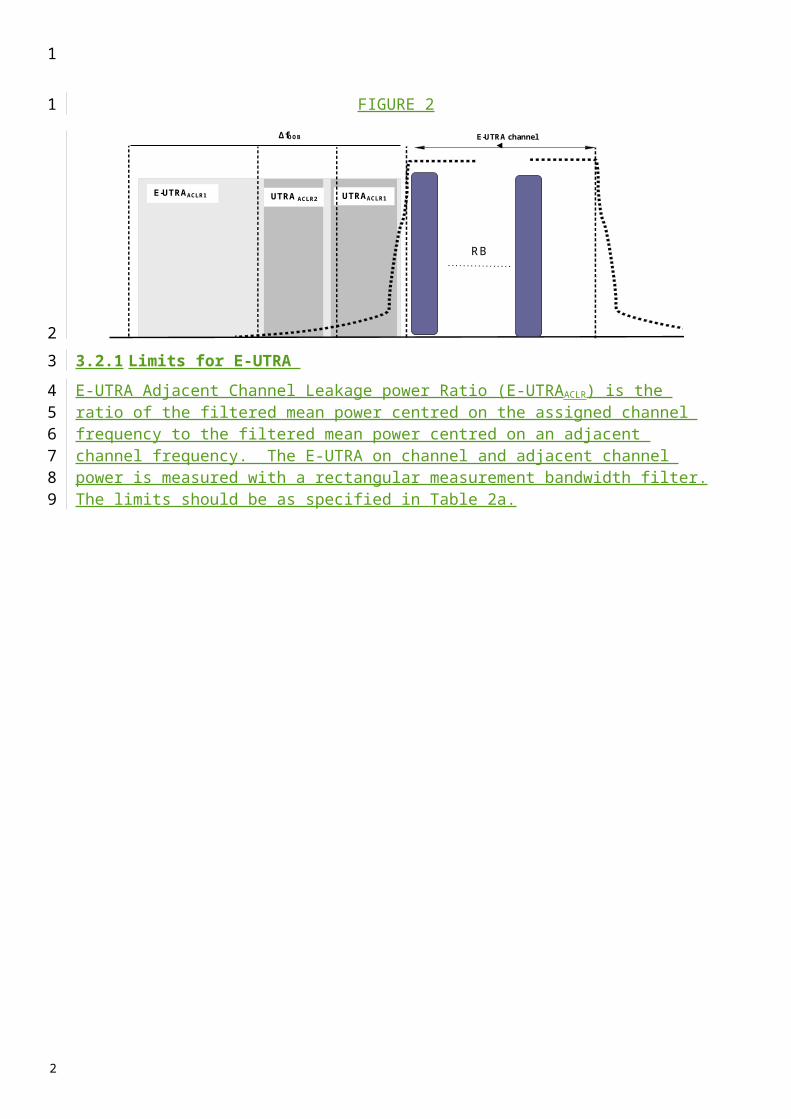
The power level of all modulation products (including AM products due to the switching on or off of a modulated RF carrier) arising from a transmission on RF channel M should, when measured using a peak hold technique, be less than the values given in Table 31.
TABLE 31
Emissions due to transmitter transients
4 Transmitter spurious emissions (conducted)
4.1 Spurious emissions when allocated a transmit channel
The spurious emissions, when a radio end point has an allocated physical channel, should meet the requirements of Table 32. The requirements of Table 32 are only applicable for frequencies which are greater than 12.5 MHz away from the centre frequency, fc, of a carrier.
TABLE 32
Spurious emissions requirements
Measurements should not be made for transmissions on the RF channel closest to the nearest band edge for frequency offsets of up to 2 MHz.
5 Receiver spurious emissions (idle mode)
5.1 Spurious emissions when the EUT has no allocated transmit channel
The power level of any spurious emissions when the radio end point has no allocated transmit channel should not exceed the limits specified in Table 33.
Emissions on RF channel “Y ” Measurement bandwidth Maximum power level
Y M 1 (1) 250 mW (–6 dBm)Y M 2 (1) 40 mW (–14 dBm)Y M 3 (1) 4 mW (–24 dBm)
Y any other DECT channel (1) 1 mW (–30 dBm)(1) The measurement bandwidth should be 100 kHz and the power should be integrated over a 1 MHz bandwidth centred on the DECT frequency, FY.
Frequency Minimum requirement/ Reference bandwidth
30 MHz f 1 000 MHz –36 dBm/100 kHz1 GHz f 12.75 GHz –30 dBm/1 MHz
fc – 12.5 MHz f fc 12.5 MHz Not defined
1
123
4
5
7
8
91011
12
13
15
1617
18
19
2021
22
2

TABLE 33
Receiver spurious emissions
5.2 In the DECT band
The power level of any receiver spurious emissions within the DECT band should not exceed the limit in Table 34.
TABLE 34
Receiver spurious emissions within DECT band
Frequency band Measurement bandwidth
Maximum level
(dBm)Note
30 MHz f 1 GHz 100 kHz (1) –57
1 GHz f 12.75 GHz 1 MHz (1) –47 With the exception of the frequencies
within the DECT band, covered by Table 34
(1) The power should be measured using a peak hold technique.
Frequency band(MHz)
Measurement bandwidth
(MHz)
Maximum level(dBm)
1 900-1 920 2 010-2 025 1 –57(1)
(1) The following exceptions are allowed:
– in one 1 MHz band, the maximum allowable e.r.p. should be less than 20 nW;
– in up to two bands of 30 kHz, the maximum e.r.p. should be less than 250 nW.
1
1
2
4
5
67
8
9
2
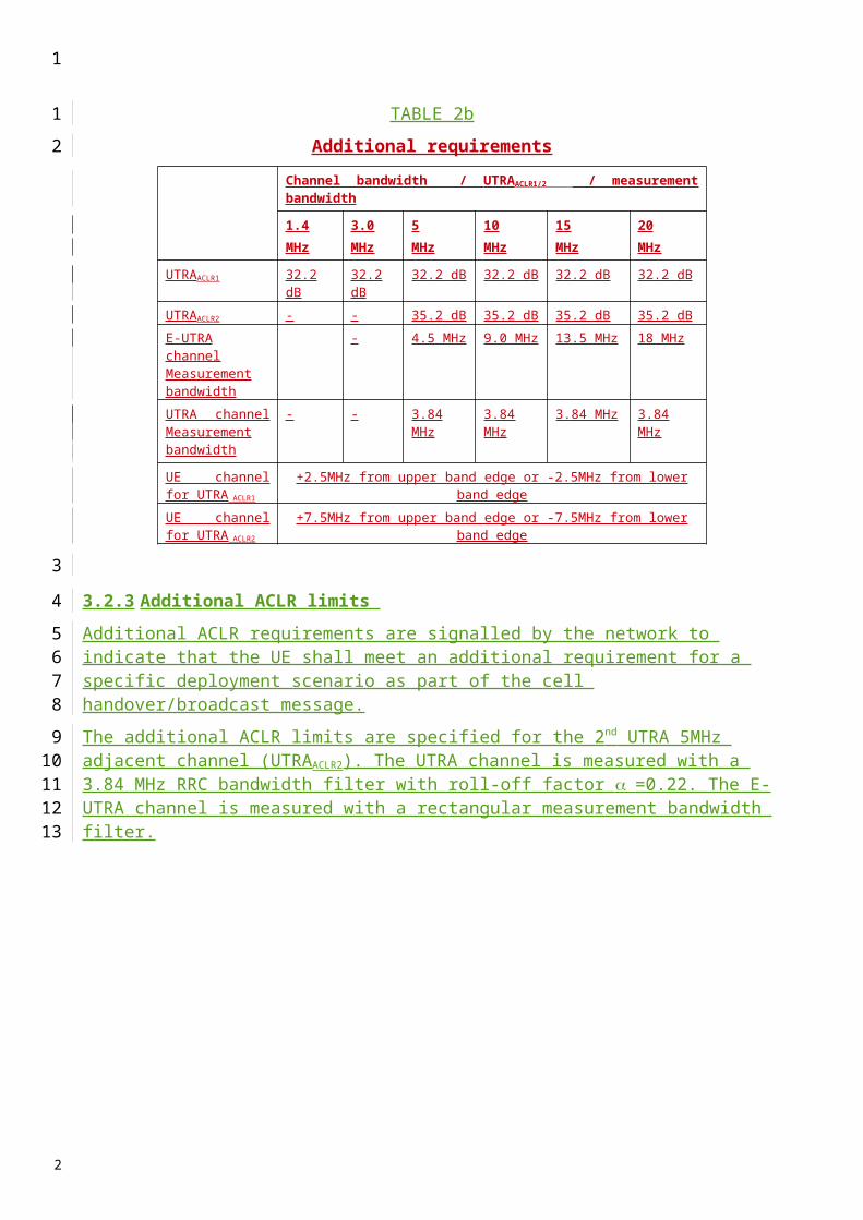
Annex 6
IMT 2000 OFDMA TDD WMAN mobile stations
This Annex defines the unwanted emission limits for IMT-2000 OFDMA TDD WMAN mobile stations.
1 Spectrum emission mask
1.1 Spectrum emission mask for equipment operating in the band 2 300-2 400 MHz
TBD
1.2 Spectrum emission mask for equipment operating in the band 2 500-2 690 MHz
The spectrum emission mask of user equipment applies to frequencies between 2.5 MHz and 12.5 MHz away from the user equipment centre frequency for the 5 MHz carrier and between 5 MHz and 25 MHz away from the user equipment centre frequency for the 10 MHz carrier.
TABLE 35
Spectrum emission mask for 10 MHz carrier
Segment number
Offset from channel centre frequency
(MHz)
Integration bandwidth
(kHz)
Allowed emission level(dBm/integration bandwidth)
1 5 to < 6 100 −13.002 6 to < 10 1 000 −13.003 10 to < 11 1 000 −13 − 12(f − 10)4 11 to < 15 1 000 −25.00
5 15 to < 20 1 000If PTx,max ≤ +23 dBm and 2 550 ≤ fc≤ 2 620 MHz then
−21 − 32/19 × (f −10.5) else −25
6 20 to < 25 1 000If PTx,max ≤ +23 dBm and 2 550 ≤ fc≤ 2 620 MHz then
−37.00 else −25
NOTE 1 – Maximum transmitter output power of user equipment is 23 dBm or smaller in Japan, and the frequency band of operation is limited to 2 545-2 625 MHz.
In Table 35:– Channel bandwidth is 10 MHz.– Integration bandwidth refers to the frequency range over which the emission power is
integrated.– f is defined as the frequency offset in MHz from the channel centre frequency.
1
123
45
6
7
8
9
101112
13
14
15
1617181920
2

– PTx,max is the maximum declared output power for the user equipment.
1
1
2
2

TABLE 36
Spectrum emission mask for 5 MHz carrier
Segment number
Offset from channel centre frequency
(MHz)
Integration bandwidth
(kHz)
Allowed emission level(dBm/integration bandwidth)
1 2.5 to < 3.5 50 −13.002 3.5 to < 7.5 1 000 −13.00
3 7.5 to < 8 1 000If PTx,max ≤ +23 dBm and
2 547.5 ≤ fc≤ 2 622.5 MHz then −20 − 2.28 × (f − 7.5) else −13.00
4 8 to < 10.4 1 000 −25.00
5 10.4 to < 12.5 1 000If PTx,max ≤ +23 dBm and
2 547.5 ≤ fc≤ 2 622.5 MHz then −21 − 1.68 × (f − 8) else −25
NOTE 1 – Maximum transmitter output power of user equipment is 23 dBm or smaller in Japan, and the frequency band of operation is limited to 2 545-2 625 MHz.
In Table 36:– Channel bandwidth is 5 MHz.– Integration bandwidth refers to the frequency range over which the emission power is
integrated.
1.3 Spectrum emission mask for equipment operating in the band 3 400-3 600 MHz
TBD
2 Transmitter spurious emissions (conducted)
IMT-2000 OFDMA TDD WMAN user equipment complies with the limits recommended in Recommendation ITU-R SM.329-10. The limits shown in Tables 37a and 37b and 38 are only applicable for frequency offsets which are greater than 12.5 MHz away from the user equipment centre frequency for the 5 MHz carrier and greater than 25 MHz for the 10 MHz carrier. f is the frequency of the spurious domain emissions. fc is the user equipment center frequency.
The emission levels in Table 37a should be met in areas where Category A levels for spurious emissions, as defined in Recommendation ITU-R SM.329-10, are applicable. The emission levels in Table 37b8 should be met in areas where Category B levels for spurious emissions, as defined in Recommendation ITU-R SM.329-10, are applicable.
1
1
2
3456
7
8
9
1011121314
15161718
2

TABLE 37a
User equipment spurious emissions limits – Category A
Band Measurement bandwidth Allowed emission level
9 kHz f 150 kHz 1 kHz −13 dBm150 kHz f 30 MHz 10 kHz −13 dBm
30 MHz f 1 000 MHz 100 kHz –13 dBm1 GHz f 13.45 GHz 1 MHz –13 dBm
TABLE 37b
User equipment spurious emissions limits – Category BBand Measurement bandwidth Allowed emission level
9 kHz f 150 kHz 1 kHz −13150 kHz f 30 MHz 10 kHz −13
30 MHz f 1 000 MHz 100 kHz –36 dBm
1 GHz f 13.45 GHz30 kHz If 2.5 × BW ≤ | fc − f | < 10 × BW300 kHz If 10 × BW ≤ | fc − f | < 12 × BW1 MHz If 12 × BW ≤ | fc − f |
–30 dBm
TABLE 37
General user equipment spurious emissions limitBand Measurement bandwidth Allowed emission level
9 kHz f 150 kHz 1 kHz −13150 kHz f 30 MHz 10 kHz −13
30 MHz f 1 000 MHz 100 kHz –36 dBm
1 GHz f 13.45 GHz30 kHz If 2.5 × BW ≤ | fc − f | < 10 × BW300 kHz If 10 × BW ≤ | fc − f | < 12 × BW1 MHz If 12 × BW ≤ | fc − f |
–30 dBm
1
1
2
3
4
5
6
7
2
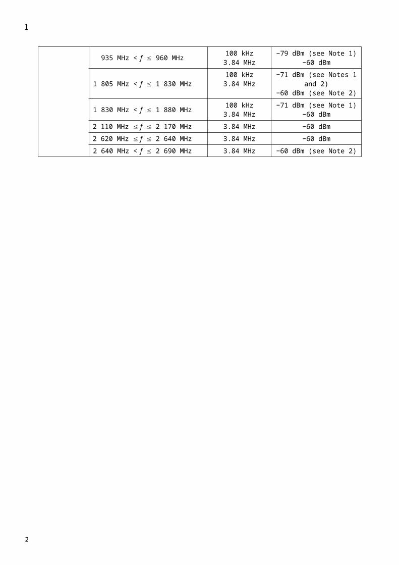
TABLE 38
Additional user equipment spurious emission limit for equipment operating in the range 2 500-2 690 MHz
Frequency bandwidthMeasure-
ment bandwidth
Minimum requirement(dBm) Note
1 000 MHz f 2 505 MHz 1 MHz −132 505 MHz f 2 530 MHz 1 MHz −372 530 MHz f 2 535 MHz 1 MHz 1.7f − 4 338
2 535 MHz f 2 630 MHz 1 MHz
−21 − 1.68*(f − 8) 12.5 MHz < f < 17.5 MHz−37 17.5 MHz < f < 22.5 MHz−18 22.5 MHz < f
For 5 MHz channel size
−18 25 MHz < f For 10 MHz channel size
2 630 MHz f 2 630.5 MHz 1 MHz −13 − 8/3.5 × (f − 2 627)
2 630.5 MHz f 2 640 MHz 1 MHz −21 − 16/9.5× (f − 2 630.5)
2 640 MHz f 2 655 MHz 1 MHz −372 655 MHz f 1 MHz −13
NOTE 1 – The allowed emission level shall be applied for the frequency range greater than 2.5 times the channel size from the centre frequency. f is the offset from channel centre frequency.NOTE 2 – This additional requirement provides for the protection of satellite systems in the bands 2 500-2 535 MHz and 2 630-2 690 MHz in Japan, and applies only to terminals operating in the frequency band 2 545-2 625 MHz with powers of 23 dBm or smaller.NOTE 3 – The update of the values in this Table is for further study.
3 Receiver spurious emissions (conducted)
The power of any narrow-band spurious emission should not exceed the maximum level specified in Table 39.
TABLE 39
General receiver spurious emission requirements
Band Measurement bandwidth Allowed emission level(dBm)
30 MHz f 1 GHz 100 kHz −57
1 GHz f 13.45 GHz
30 kHz If 2.5 × BW ≤ | fc − f | < 10 × BW300 kHz If 10 × BW ≤ | fc − f | < 12 × BW1 MHz If 12 × BW ≤ | fc − f |
−47
1
1
23
4
56
7
8
9
2
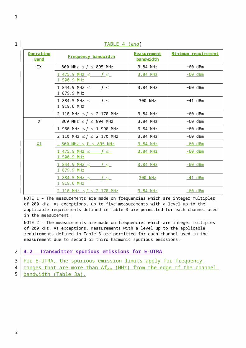
4 Adjacent channel leakage ratio (ACLR)
4.1 ACLR of equipment operating in the frequency range 2 300-2 400 MHz
TBD
4.2 ACLR of equipment operating in the frequency range 2 500-2 690 MHz
Within this Annex, and in a similar manner to other annexes, the ACLR is defined as the ratio of the on-channel transmitted power to the power transmitted in adjacent channels as measured at the output of the receiver filter. In order to measure ACLR, it is necessary to consider a measurement filter for the transmitted signal as well as a receiver measurement bandwidth for the adjacent channel (victim) system.
In this Annex, data is provided that is relevant to the case where the adjacent system is OFDMA TDD WMAN (intra-system) or the case where the adjacent system is UTRA (inter-system).
ACLR is therefore specified considering the following receiver bandwidths:
When the adjacent system is OFDMA TDD WMAN:– 4.75 MHz for a 5 MHz channelized system, and– 9.5 MHz for a 10 MHz channelized system.
When the adjacent system is UTRA:– 3.84 MHz for a 5 MHz channelized system, and– 7.68 MHz for a 10 MHz channelized system.
The measurement bandwidth for the measurement of on-channel power of the OFDMA TDD WMAN carrier is:– 4.75 MHz for a 5 MHz channelized system, and– 9.5 MHz for a 10 MHz channelized system.
The passband of the receiver filter is centred on the first or second adjacent channel centre frequency. In the case where the adjacent system is OFDMA TDD WAN, both the transmitted power and the received power are measured with a rectangular filter. For adjacent UTRA systems the transmitted power is measured using a rectangular filter and the received power using a RRC filter with a roll-off factor of 0.22.
The ACLR values for the two relevant cases are provided in the Tables 40 and 41.
TABLE 40
MS ACLR for 5 MHz channel bandwidth
Minimum required ACLR relative to assigned channel frequency (dB)
Adjacent channel centre frequency OFDMA TDD WMAN case UTRA(1) caseMS channel centre frequency ± 5 MHz 30 33MS channel centre frequency ± 10 MHz 44 43(1) These are similar to the minimum requirements for UTRA systems (see Annexes 1 and 3 to this Recommendation) and in practice may be expected to be larger.
1
1
2
3
4
56789
1011
12
131415
161718
19202122
2324252627
28
29
30
2

TABLE 41
MS ACLR for 10 MHz channel bandwidth
Minimum required ACLR relative to assigned channel frequency (dB)
Adjacent channel centre frequency OFDMA TDD WMAN case UTRA(1) caseMS channel centre frequency ± 10 MHz 30 33MS channel centre frequency ± 20 MHz 44 43(1) These are similar to the minimum requirements for UTRA systems (see Annexes 1 and 3 to this Recommendation) and in practice may be expected to be larger.
Additional information may be provided in future revisions of this Recommendation.NOTE 1 – Further study is necessary for other systems wherever applicable, as well as the relationship between ACLR and the emission mask.
4.3 ACLR of equipment operating in the frequency range 3 400-3 600 MHz
TBD
Appendix 1 – Definitions and Abbreviations
Test tolerance
With reference to Recommendation ITU-R M.1545, “test tolerance” is the relaxation value referred to in recommends 2 of ITU-R M.1545, i.e. the difference between the core specification value and the test limit, evaluated applying the shared risk principle as per figures 2 and 3 of annex 1 of ITU-R M.1545. In case the core specification value is equal to the test limit (Figure 3 of Annex 1 of ITU-R M.1545) the “test tolerances” are equal to 0.
______________
1
1
2
345
6
7
8
9
10
11
12
13
14
1516171819
20
21
22
2