Radio Wave Propagation2
38
RADIO WAVE PROPAGATION LAYERS USED POWER DENSITY ELECTRIC FIELD INTENSITY
-
Upload
erka-frnces -
Category
Documents
-
view
12 -
download
1
description
Radio Wave Propagation2RADIO WAVE PROPAGATIONLAYERS USEDPOWER DENSITYELECTRIC FIELD INTENSITYhug the contour of the earth and are affected by the terrainantenna must be vertically polarizedantenna must project the signal at a very small radiation angle so that the energy is not transmitted toward the atmosphere instead along the ground
Transcript of Radio Wave Propagation2

RADIO WAVE PROPAGATION
LAYERS USED
POWER DENSITY
ELECTRIC FIELD INTENSITY
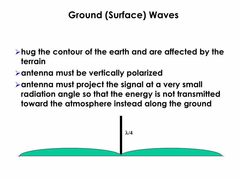
hug the contour of the earth and are affected by the
terrain
antenna must be vertically polarized
antenna must project the signal at a very small
radiation angle so that the energy is not transmitted
toward the atmosphere instead along the ground
/4
Ground (Surface) Waves
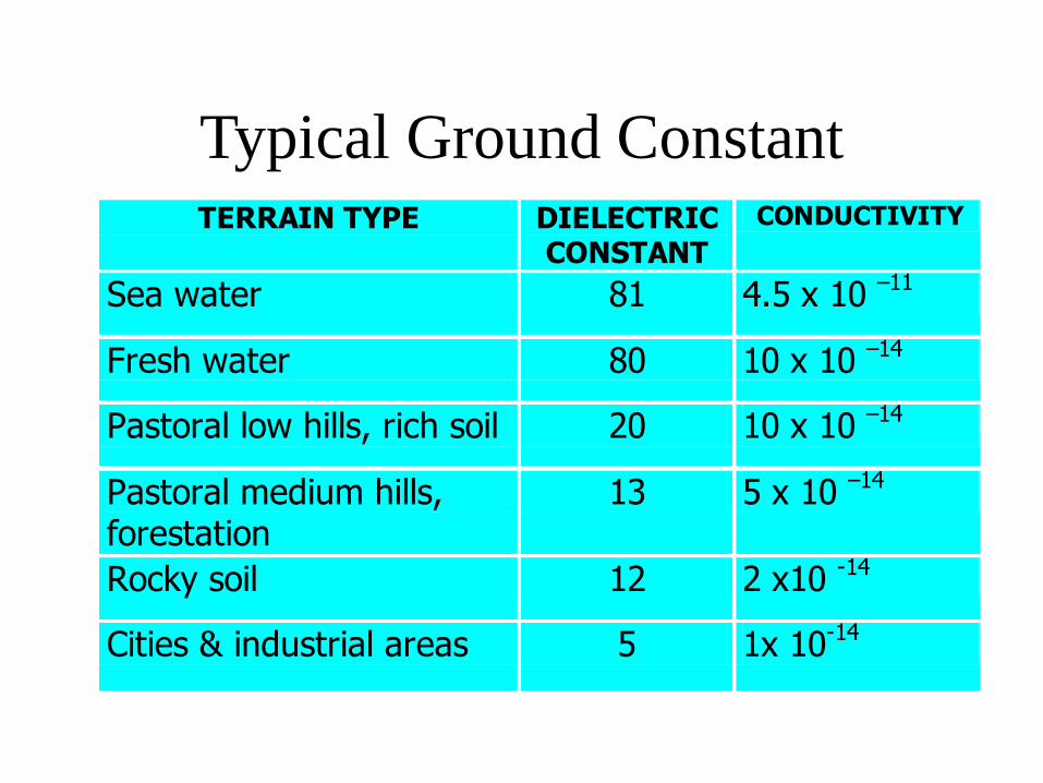
Typical Ground ConstantTERRAIN TYPE DIELECTRIC
CONSTANT
CONDUCTIVITY
Sea water 81 4.5 x 10 –11
Fresh water 80 10 x 10 –14
Pastoral low hills, rich soil 20 10 x 10 –14
Pastoral medium hills, forestation
13 5 x 10 –14
Rocky soil 12 2 x10 -14
Cities & industrial areas 5 1x 10-14

SOMMERFELD ANALYSIS on GWP
d
HT
TX
E =A E 1
d
Where:
E - Ground Wave Field Strength
A = factor affecting ground conductivity
d - Distance from transmitting antenna
E1 = electric field intensity at a unity distance
RX
HR

Problem
8. A police radio transmitter operating at a frequency of 1690 kHz
is required to provide a ground-wave having a field strength of at
least 0.5 mV/m at a distance of 10 miles. The transmitter antenna
is expected to have an efficiency of 50 %, thus, it radiates 50 % of
the energy actually delivered to it and produces a radiated field
that is proportional to the cosine of the angle of elevation. The
ground is such that a conductivity of 5 x 10 -14 emu and dielectric
constant of 15 can be expected resulting to a ground constant of 0.15.
Determine the transmitter power required.64.24 watts

Direct (Space) Waves
are useful primarily only in VHF and UHF bands.
VHF and UHF signals are easily reflected by
buildings, hills, and even airplanes, so some of your
signal reach the other station by a direct path and
some may be reflected
Direct or space wave travel in a straight line from
transmitting antenna to receiving antenna
is referred to as line-of-sight propagation
TV and FM radio broadcasts

Problem
10. In a VHF mobile radio system, the base station transmits
100 watts at 150 MHz, and the antenna is 20 m above ground.
The transmitting antenna is /2 dipole for which the gain is 1.64.
Calculate the field strength at a receiving antenna of height 2 m
at a distance of 40 km.
11. Using the data in no. 1, find the a) path difference of the
radiated wave and b) their phase difference.
11 V/m
2 mm ; 6.28 x10 -3 rad/s

d2
D
R R
R
Direct (Space) Waves
Path Distance
d1

d2
D
R’ R’
R’
A
B
C
D
Direct (Space) Waves
Path Distance
d1
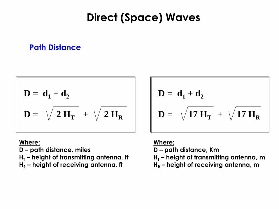
Direct (Space) Waves
D = d1 + d2
D = 2 HT 2 HR+
Where:
D – path distance, miles
HT – height of transmitting antenna, ft
HR – height of receiving antenna, ft
D = d1 + d2
D = 17 HT 17 HR+
Where:
D – path distance, Km
HT – height of transmitting antenna, m
HR – height of receiving antenna, m
Path Distance

Problem
9. Calculate the maximum distance at which a receiving
antenna of 200 ft be constructed away from a transmitting
antenna of 400ft considering line-of-sight condition with
k=4/3.
48.28 mi

Direct and Ground Reflected Waves
CHARACTERISTICS:
The received power is a function of the frequency of the radiated field.
The received power is a function of the (transmit and receive) antenna heights.
This model is valid for relatively low antenna elevations and frequencies of 50
MHz and above
This model assumes a plane earth and does not take into account the curvature
of the earth
Propagation Over Plane Earth
HT
HR
D
Direct Path
Reflected Path
ER

Propagation Over Plane Earth
ER =4 Ht Hr
D Ed
Where:
ER - Resulting Field Strength ; v/m
Ed - Direct Ray Field strength; v/m
HT - Height of transmitting antenna ; m
HR - Height of receiving antenna ; m
D - Path distance ; m
Tropospheric Propagations
Ed =
30 G Pt
D
Tropospheric Propagations
is the region of the earth's atmosphere immediately
adjacent to the earth surface
Tropospheric scatter is the method of propagating
microwave energy beyond LOS or over the horizon
takes advantage of the refraction and reflection
phenomena
causes signals to return to Earth beyond the
geometric horizon, and allows you to contact stations
that are farther away than would otherwise be
possible
TROPOSPHERE

This radio path horizon is generally about 15% farther
away than the visible horizon.
TROPOSPHERE
Tropospheric Propagations
Radio signals can be trapped in the troposphere,
traveling a longer distance than normal before
coming back to the Earth's surface
The area between the Earth and the warm air mass is
known as a duct
Ducts usually form over water, but they can also form
over land
Tropospheric ducting is the most common type of
enhanced propagation at UHF
Ducting-Super refractions
Tropospheric Propagations

Tropospheric Ducting

Ionospheric Propagations - Sky Waves
is aimed not at the intended receiver but at the sky
takes advantage of the ionosphere that surrounds the
earth to provide worldwide communications
radiate signal toward ionosphere and have it refract
and return to earth
Some of the signal passes through the layers of the
ionosphere and out into space, but enough returns to
earth to be picked up by a sensitive receiver
SKY WAVE

Transmittedwave
Reflectedwave
Refractedwave
Skip distance
Ionosphere
SKY WAVE
Ionospheric Propagations - Sky Waves


is the layer of partially ionized gas that is above the
oxygen-rich layer we live
absorbs large quantities of radiant energy from the
sun, becoming heated and ionized
The ionization is caused by ultraviolet radiation's from the sun
The amount of ionization depends on many factors:
amount of sunlight, seasons of the year, sunspot, weather conditions and local terrain
If the wave is bent enough, it returns to Earth
If the wave is not bent enough, it travels off into space
IONOSPHERE
Ionospheric Propagations - Sky Waves

IONOSPHERE
The ionosphere consist of a series of layers
varying ion density at different height (D, E, F1 & F2 layers)
Ionospheric Propagations - Sky Waves
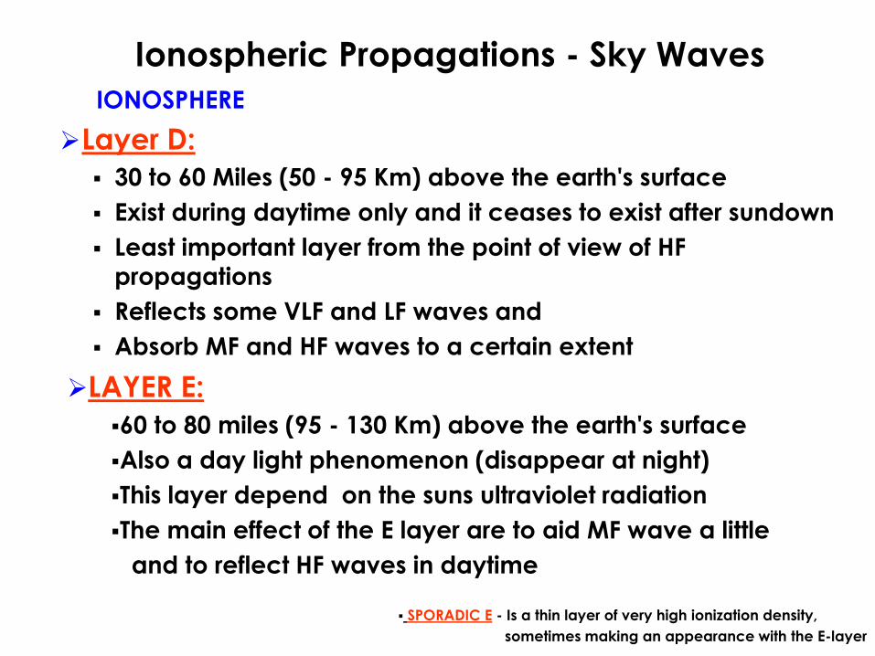
Layer D:
30 to 60 Miles (50 - 95 Km) above the earth's surface
Exist during daytime only and it ceases to exist after sundown
Least important layer from the point of view of HF
propagations
Reflects some VLF and LF waves and
Absorb MF and HF waves to a certain extent
IONOSPHERE
Ionospheric Propagations - Sky Waves
SPORADIC E - Is a thin layer of very high ionization density,
sometimes making an appearance with the E-layer
LAYER E:
60 to 80 miles (95 - 130 Km) above the earth's surface
Also a day light phenomenon (disappear at night)
This layer depend on the suns ultraviolet radiation
The main effect of the E layer are to aid MF wave a little
and to reflect HF waves in daytime
Layer F:
F1 100 to 155 miles (160 - 250 Km)
Provide more absorption for HF waves but some are reflected
from it
F2 155 to 250 miles (250 -400 Km)
Most important reflecting medium for HF radio waves
Most HF waves pass through to F2 where they are refracted
back to Earth
F1 and F2 are separate during daylights and merge after
sunset/nighttime (F-layer)
Most highly ionized, and hence there is some chance for the ionization to remain at night
Higher ion density means, the more refraction (bending)
IONOSPHERE
Ionospheric Propagations - Sky Waves

Effects of Ionospheric Density on Radio waves

Ionospheric Propagations - Sky Waves
Relative Permittivity( R)
Where:
R - Relative Permittivity (dielectric constant of the ionized layer)
N - Electron Density ; m -3
m - Electron Mass ; 9.11 x 10 -31 Kg
qe - Electron Charge ; 1.6 x 10 -19 C
- Angular frequency ; rad/sec
o - Permittivity of Free Space
R =N qe2
1 -o m 2

Ionospheric Propagations - Sky Waves
Plasma Frequency (Fp)
Angular velocity of the wave can have a value that makes R
equal to zero, this is the plasma angular frequency p
FP = 9 N
p = N qe2
o m

Ionospheric Propagations - Sky Waves
Critical Frequency (FC)
A wave of low frequency that is sent vertically toward
the ionosphere will be reflected back to the
transmitter
The highest frequency wave that will be reflected from
a given layer when the wave is at vertical incidence
Is a plasma frequency from a given layer
The equipment used to measure the virtual height of
the ionosphere is called an ionosonde
FC = 9 Nmax

Ionospheric Propagations - Sky Waves
Maximum Usable Frequency (MUF)
The critical frequency for the layer is an indication of
the highest frequency, called MUF
MUF is the highest frequency that will be reflected
from a given layer and return to earth at a given
angle of radiation
The frequency at which communication just starts to
fail is known as the Maximum Usable Frequency (MUF)
MUF = FC Sec i

Ionospheric Propagations - Sky Waves
Optimum Working Frequency (OWF)
Because of the general instability of the ionosphere, the optimum working frequency is used instead.
The highest frequency that can be used for sky wave
propagations between two points on the earth
OWF = 0.85 MUF

Frequency versus Refraction and Distance

Incidence angles of Radio Waves

Effect of Frequency on the Critical Angle

Problem
12. Two points on earth 1500km apart are to
communicate by means of HF. Given that this is to
be a single hop transmission, the critical frequency
at that time is 6 MHz and the conditions are
idealized. Calculate the maximum usable frequency
if the height of the ionosphere is 350 km.
14.188 MHz

Problem
13. A wave travelling in free space undergoes refraction
after it enters a denser region such that the original
25º angle of incidence at the boundary of the two
media is changed to 20º. What is the velocity of the
EM wave in the denser medium?
2.43 x 10 8 m/s

Problem
14. Calculate the transmission path distance for an
ionospheric transmission that utilizes a layer of
virtual height 200 km. The angle of elevation of the
antenna beam is 20º.
d = 2R ( R
R + h
2) sin -1 cos )(
1100 km
966 km
d = 2h / tan

TERMS• If the radiated energy comes from another radio
transmitter, then it is considered radio-frequency
interference (RFI)
• If the energy comes from else where, then it is
electromagnetic interference (EMI)
• Isothermal region Temperature in the stratosphere is
believed to be fairly constant and is not subject to
temperature changes or inversions and will not cause
significant refractions

TERMS
• Sunspots are relatively cool areas that appear as dark
blemishes on the face of the sun. They are formed
when magnetic field lines just below the sun's surface
are twisted and poke though the solar photosphere.
• Solar flares emit high-speed particles which cause
auroras, known in the northern hemisphere as
Northern Lights. From the ground auroras appear as
shimmering curtains of red and green light in the sky.