Radio Test Report per AS/NZS 4268:2008 + A1:2010...Test Certificate A sample of the following...
83
Test Certificate A sample of the following product received on October 19, 2010 and tested on September 1 and 6 and November 11, 2011 and January 4, 9, 10 and 12, 2012 complied with the requirements of AS/NZS 4268:2008 +A1:2010 Radio equipment and systems – Short range devices – limits and methods of measurement given the measurement uncertainties detailed in Elliott report R86848. Summit Data Communications Model SDC-SSD40NBT _____________________ _______________________ Mark E Hill Summit Data Communications Staff Engineer _______________________ Printed Name Elliott Laboratories is accredited by the A2LA, certificate number 2016.01, to perform the test(s) listed in this report, except where noted otherwise. This report and the information contained herein represent the results of testing test articles identified and selected by the client performed to specifications and/or procedures selected by the client. National Technical Systems (NTS) makes no representations, expressed or implied, that such testing is adequate (or inadequate) to demonstrate efficiency, performance, reliability, or any other characteristic of the articles being tested, or similar products. This report should not be relied upon as an endorsement or certification by NTS of the equipment tested, nor does it represent any statement whatsoever as to its merchantability or fitness of the test article, or similar products, for a particular purpose. This report shall not be reproduced except in full Elliott Laboratories 41039 Boyce Road 510-578-3500 Phone www.elliottlabs.com Fremont, CA. 94538-2435 510-440-9525 Fax
Transcript of Radio Test Report per AS/NZS 4268:2008 + A1:2010...Test Certificate A sample of the following...
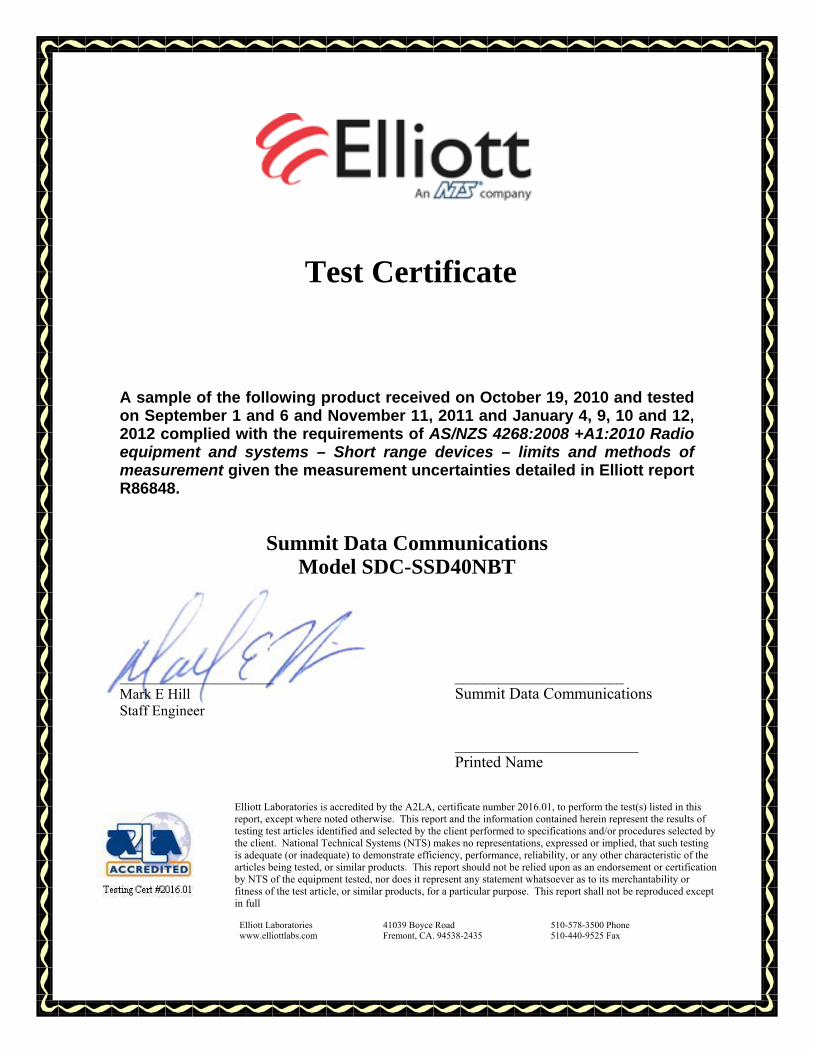
Test Certificate
A sample of the following product received on October 19, 2010 and tested on September 1 and 6 and November 11, 2011 and January 4, 9, 10 and 12, 2012 complied with the requirements of AS/NZS 4268:2008 +A1:2010 Radio equipment and systems – Short range devices – limits and methods of measurement given the measurement uncertainties detailed in Elliott report R86848.
Summit Data Communications Model SDC-SSD40NBT
_____________________ _______________________ Mark E Hill Summit Data Communications Staff Engineer _______________________ Printed Name
Elliott Laboratories is accredited by the A2LA, certificate number 2016.01, to perform the test(s) listed in this report, except where noted otherwise. This report and the information contained herein represent the results of testing test articles identified and selected by the client performed to specifications and/or procedures selected by the client. National Technical Systems (NTS) makes no representations, expressed or implied, that such testing is adequate (or inadequate) to demonstrate efficiency, performance, reliability, or any other characteristic of the articles being tested, or similar products. This report should not be relied upon as an endorsement or certification by NTS of the equipment tested, nor does it represent any statement whatsoever as to its merchantability or fitness of the test article, or similar products, for a particular purpose. This report shall not be reproduced except in full
Elliott Laboratories 41039 Boyce Road 510-578-3500 Phone www.elliottlabs.com Fremont, CA. 94538-2435 510-440-9525 Fax

Radio Test Report
AS/NZS 4268:2008 +A1:2010 Radio equipment and systems – Short range devices –
limits and methods of measurement RLAN Device Operating in the 2400-2483.5 MHz,
5150-5250 MHz, 5470-5725 MHz Band(s)
Model: SDC-SSD40NBT COMPANY: Summit Data Communications 526 South Main St. Suite 805 Akron, OH 44311 TEST SITE(S): Elliott Laboratories 41039 Boyce Road. Fremont, CA. 94538-2435 REPORT DATE: March 20, 2012 FINAL TEST DATES: September 1 and 6 and November 11, 2011 and
January 4, 9, 10 and 12, 2012 TOTAL NUMBER OF PAGES: 83 PROGRAM MGR / QUALITY ASSURANCE DELEGATE / TECHNICAL REVIEWER: FINAL REPORT PREPARER: ______________________________ ______________________________ Mark E Hill David Guidotti Staff Engineer Senior Technical Writer
Elliott Laboratories is accredited by the A2LA, certificate number 2016.01, to perform the test(s) listed in this report, except where noted otherwise. This report and the information contained herein represent the results of testing test articles identified and selected by the client performed to specifications and/or procedures selected by the client. National Technical Systems (NTS) makes no representations, expressed or implied, that such testing is adequate (or inadequate) to demonstrate efficiency, performance, reliability, or any other characteristic of the articles being tested, or similar products. This report should not be relied upon as an endorsement or certification by NTS of the equipment tested, nor does it represent any statement whatsoever as to its merchantability or fitness of the test article, or similar products, for a particular purpose. This report shall not be reproduced except in full
File: R86848 Page 2

Elliott Laboratories -- EMC Department Test Report Report Date: March 20, 2012
File: R86848 Page 3
REVISION HISTORY Rev# Date Comments Modified By
- 03-20-2012 First release
Elliott Laboratories -- EMC Department Test Report Report Date: March 20, 2012
File: R86848 Page 4
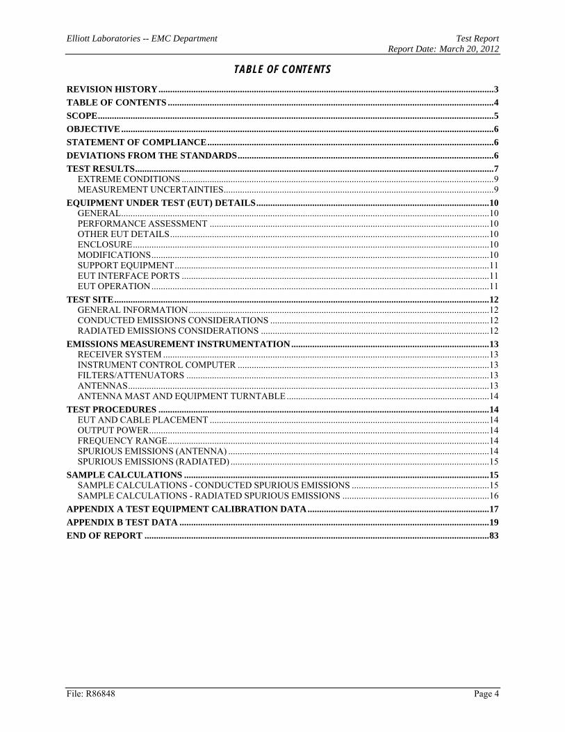
TABLE OF CONTENTS REVISION HISTORY ................................................................................................................................................ 3 TABLE OF CONTENTS ............................................................................................................................................ 4 SCOPE .......................................................................................................................................................................... 5 OBJECTIVE ................................................................................................................................................................ 6 STATEMENT OF COMPLIANCE ........................................................................................................................... 6 DEVIATIONS FROM THE STANDARDS .............................................................................................................. 6 TEST RESULTS .......................................................................................................................................................... 7
EXTREME CONDITIONS ...................................................................................................................................... 9 MEASUREMENT UNCERTAINTIES .................................................................................................................... 9
EQUIPMENT UNDER TEST (EUT) DETAILS .................................................................................................... 10 GENERAL .............................................................................................................................................................. 10 PERFORMANCE ASSESSMENT ........................................................................................................................ 10 OTHER EUT DETAILS ......................................................................................................................................... 10 ENCLOSURE ......................................................................................................................................................... 10 MODIFICATIONS ................................................................................................................................................. 10 SUPPORT EQUIPMENT ....................................................................................................................................... 11 EUT INTERFACE PORTS .................................................................................................................................... 11 EUT OPERATION ................................................................................................................................................. 11
TEST SITE ................................................................................................................................................................. 12 GENERAL INFORMATION ................................................................................................................................. 12 CONDUCTED EMISSIONS CONSIDERATIONS .............................................................................................. 12 RADIATED EMISSIONS CONSIDERATIONS .................................................................................................. 12
EMISSIONS MEASUREMENT INSTRUMENTATION ..................................................................................... 13 RECEIVER SYSTEM ............................................................................................................................................ 13 INSTRUMENT CONTROL COMPUTER ............................................................................................................ 13 FILTERS/ATTENUATORS .................................................................................................................................. 13 ANTENNAS ........................................................................................................................................................... 13 ANTENNA MAST AND EQUIPMENT TURNTABLE ....................................................................................... 14
TEST PROCEDURES .............................................................................................................................................. 14 EUT AND CABLE PLACEMENT ........................................................................................................................ 14 OUTPUT POWER .................................................................................................................................................. 14 FREQUENCY RANGE .......................................................................................................................................... 14 SPURIOUS EMISSIONS (ANTENNA) ................................................................................................................ 14 SPURIOUS EMISSIONS (RADIATED) ............................................................................................................... 15
SAMPLE CALCULATIONS ................................................................................................................................... 15 SAMPLE CALCULATIONS - CONDUCTED SPURIOUS EMISSIONS ........................................................... 15 SAMPLE CALCULATIONS - RADIATED SPURIOUS EMISSIONS ............................................................... 16
APPENDIX A TEST EQUIPMENT CALIBRATION DATA .............................................................................. 17 APPENDIX B TEST DATA ..................................................................................................................................... 19 END OF REPORT .................................................................................................................................................... 83

Elliott Laboratories -- EMC Department Test Report Report Date: March 20, 2012
File: R86848 Page 5
SCOPE Electromagnetic compatibility test data has been taken pursuant to the relevant requirements of AS/NZS 4268:2008 +A1:2010 “Radio Equipment and systems – Short range devices – Limits and methods of measurement”. This standard references the following documents:
• ANSI C63.4 American National Standard for Methods of Measurement of Radio-Noise Emissions from Low-Voltage Electrical and Electronic Equipment in the Range of 9 kHz to 40 GHz
• EN 300 328-1 V1.7.1 Electromagnetic Compatibility and Radio Spectrum Matters (ERM); Wideband transmission systems; Data transmission equipment operating in the 2,4 GHz ISM band and using spread spectrum modulation techniques; Part 1 : Technical characteristics and test conditions
• EN 301 893 V1.5.1 Broadband Radio Access Networks (BRAN); 5 GHz high performance RLAN; Harmonised EN covering essential requirements of article 3.2of the R&TTE Directive
• EN 300 440-1 V1.4.1 Electromagnetic Compatibility and Radio spectrum Matters (ERM); Short range devices; Radio equipment to be used in the 1 GHz to 40 GHz frequency range Part 1: Technical characteristics and test methods
• ETR 273-1-1 Electromagnetic Compatibility and Radio spectrum Matters (ERM); Improvement of radiated methods of measurement (using test sites) and evaluation of the corresponding measurement uncertainties
• Australian Communications Authority Radiocommunications (Low Interference Potential Devices) Class Licence 2000, compilation prepared on 15 September 2010 taking into account amendments up to Radiocommunications (Low Interference Potential Devices) Class Licence Variation Notice 2009 (No. 1)
• New Zealand Ministry for Economic development Radiocommunications Regulations (General User Radio Licence for Short Range Devices) July 29, 2010
For results of the Bluetooth operation, refer to Elliott report R86494.

Elliott Laboratories -- EMC Department Test Report Report Date: March 20, 2012
File: R86848 Page 6
OBJECTIVE The objective of the manufacturer is to comply with AS/NZS 4268:2008 +A1:2010 for use with the following spectrum allocations and licenses:
• Australian Communications Authority Radiocommunications (Low Interference Potential Devices) Class Licence 2000 (latest release dated July 27, 2011)
• New Zealand Ministry for Economic development Radiocommunications Regulations (General User Radio Licence for Short Range Devices) Notice 2 2010 (latest release dated April 7, 2011)
In order to demonstrate compliance, the manufacturer or a contracted laboratory makes measurements and takes the necessary steps to ensure that the equipment complies with the appropriate technical standards.
STATEMENT OF COMPLIANCE
The tested sample of Summit Data Communications model SDC-SSD40NBT complied with the relevant requirements of AS/NZS 4268:2008 +A1:2010 based on classification of the system by the manufacturer in accordance with the guidelines of AS/NZS 4268:2008 +A1:2010. The test results recorded herein are based on a single type test of Summit Data Communications model SDC-SSD40NBT and therefore apply only to the tested sample. The sample was selected and prepared by Ron Seide of Summit Data Communications. Maintenance of compliance is the responsibility of the manufacturer. Any modifications to the product should be assessed to determine their potential impact on the compliance status of the device with respect to the standards detailed in this test report.
DEVIATIONS FROM THE STANDARDS
No deviations were made from the published requirements listed in the scope of this report.

Elliott Laboratories -- EMC Department Test Report Report Date: March 20, 2012
File: R86848 Page 7
TEST RESULTS Transmitters employing digital modulation techniques in the 2400 - 24835 MHz band
Section1 Description Limit Measured Status
8.1 Maximum EIRP
Australia LIPD limit: 4000 mW eirp (36dBm) New Zealand GURL limit: 1000 mW output power (30dBm) 4000 mW eirp (36dBm)
b: 19.3 dBm g: 15.3 dBm n20: 12.7 dBm all values eirp
Pass
8.2 Transmitter Spurious Emissions
Australia LIPD / New Zealand GURL limit: 25 – 25 GHz: -20dBc (spurious and fundamental measured in 100kHz)
All emissions more than 10dB below limit
Pass
8.3, 8.4 Emission Bandwidth Australia LIPD / New Zealand GURL allocated band: 2400 -2483.5 MHz
802.11b: 2405.64 - 2478.22 MHz 802.11g: 2403.44 - 2480.60 MHz 802.11n20: 2402.98-2481.12 MHz
Pass
8.3, 8.4 Operating Frequencies 2412 MHz to 2472 MHz Pass
LIPD / GURL
Maximum peak power spectral density 25mW/3kHz (14dBm/3kHz) eirp
802.11b: 8.9 dBm/MHz eirp 802.11g: 4.5 dBm/MHz eirp 802.11n20: 1.5 dBm/MHz eirp
Pass
LIPD / GURL
Minimum 6dB bandwidth 500 kHz >500kHz Pass
9 Receiver Spurious Emissions
25 MHz to 1 GHz 3.3 nW EIRP, or 2.0 nW ERP 1 GHz to 40 GHz 32.8 nW EIRP, or 20 nW ERP
All emissions more than 10dB below limit
Pass
1 Reference to the either the section of AS/NZS 4268 or the Class License (LIPD or GURL) containing the requirement.

Elliott Laboratories -- EMC Department Test Report Report Date: March 20, 2012
File: R86848 Page 8
Transmitters employing digital modulation techniques in the 5150 – 5250 MHz,
5250 – 5350 MHz and 5470 – 5600 / 5650 - 5725 MHz bands Section2
Description Limit Measured Status
8.1
Maximum EIRP 5150 – 5350 MHz
Australia LIPD / New Zealand GURL limit:
200 mW eirp, indoor use only
11a: 19.2 dBm 11n: 19.6 dBm Complies
Maximum EIRP 5250 – 5350 MHz
New Zealand GURL limit: 1000 mW eirp with vertical radiation angle mask
Not used – using general indoor-only limits
N/A
Maximum EIRP 5470 – 5725 MHz
Australia LIPD limit: 1000 mW eirp
New Zealand GURL limit: 250 mW output power 1000 mW eirp
11a: 19.6 dBm 11n: 19.4 dBm Complies
8.2 Transmitter Spurious Emissions
Australia LIPD / New Zealand GURL limit3:
25 – 25 GHz: -27dBm eirp
All emissions more than 10dB below limit
Complies
8.3, 8.4 Emission Bandwidth Operating Frequencies
Australia LIPD / New Zealand GURL allocated band:
5150 - 5350 MHz
11a: 5171.690-5328.430 MHz 11n: 5171.030-5329.060 MHz
Complies
8.3, 8.4 Emission Bandwidth Operating Frequencies
Australia LIPD allocated band: 5470 – 5600 MHz 5650 – 5725 MHz
New Zealand GURL allocated band:
5470 – 5725 MHz
11a: 5491.390-5708.370 MHz 11n: 5490.430-5709.090 MHz
Complies
LIPD Maximum peak power spectral density, 5150 – 5350 MHz
Australia LIPD 10mW/MHz (10dBm/MHz eirp ) New Zealand GURL 10mW/MHz
11a: 9.6 dBm/MHz 11n: 9.6 dBm/MHz
Complies
GURL Maximum peak power spectral density, 5250 – 5350 MHz
New Zealand GURL 50mW/MHz Requires vertical radiation angle mask
Not used – using general indoor-only limits
N/A
LIPD / GURL
Maximum peak power spectral density, 5470 – 5600 MHz/ 5650 - 5725 MHz
50mW/MHz (10dBm/MHz eirp )
11a: 9.2 dBm/MHz 11n: 8.7 dBm/MHz
Complies
LIPD / GURL
Dynamic frequency Selection (5250- 5350, 5470 – 5600 MHz/ 5650 - 5725 MHz bands)
Meet the requirements of EN 301 893 V1.2.3 or FCC regulations Refer to R86491 Complies
LIPD / GURL
Transmit power Control (5250- 5350, 5470 – 5600 MHz/ 5650 - 5725 MHz bands)
If not employed maximum eirp is reduced to 500mW for the 5470 MHz band and 100mW for the 5250 MHz band
EUT is below TPC threshold N/A
9 Receiver Spurious Emissions
25 MHz to 1 GHz 3.3 nW EIRP, or 2.0 nW ERP
1 GHz to 40 GHz 32.8 nW EIRP, or 20 nW ERP
-50.9dBm @ 3453.5MHz (-3.9dB)
2 Reference to the either the section of AS/NZS 4268 or the Class License (LIPD or GURL) containing the requirement. 3 Limit taken from FCC Part 15 Subpart E as referenced in the Radiocommunications Regulations

Elliott Laboratories -- EMC Department Test Report Report Date: March 20, 2012
File: R86848 Page 9
EXTREME CONDITIONS
Voltage extremes used during testing were 3.0VDC to 3.6VDC and are based on the manufacturer declared values for extremes. Temperature extremes used during testing were those for unrestricted use, -20°C to +55°C.
MEASUREMENT UNCERTAINTIES
ISO/IEC 17025 requires that an estimate of the measurement uncertainties associated with the emissions test results be included in the report. The measurement uncertainties given below are based on a 95% confidence level (based on a coverage factor (k=2) and were calculated in accordance with NAMAS document NIS 81 and M3003.
Measurement Type Measurement Unit Frequency Range Expanded
Uncertainty RF frequency Hz 25 to 7000 MHz 1.7 x 10⁻⁷ RF power, conducted dBm 25 to 7000 MHz ± 0.52 dB Conducted emission of transmitter dBm 25 to 26500 MHz ± 0.7 dB
Conducted emission of receiver dBm 25 to 26500 MHz ± 0.7 dB
Radiated emission (substitution method) dBm 25 to 26500 MHz ± 2.5 dB
Radiated emission (field strength) dBμV/m 25 to 1000 MHz ± 3.6 dB
Transmitter switch off time Seconds - 0.1 sec
Elliott Laboratories -- EMC Department Test Report Report Date: March 20, 2012
File: R86848 Page 10
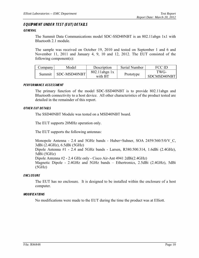
EQUIPMENT UNDER TEST (EUT) DETAILS GENERAL
The Summit Data Communications model SDC-SSD40NBT is an 802.11abgn 1x1 with Bluetooth 2.1 module. The sample was received on October 19, 2010 and tested on September 1 and 6 and November 11, 2011 and January 4, 9, 10 and 12, 2012. The EUT consisted of the following component(s):
Company Model Description Serial Number FCC ID
Summit SDC-MSD40NBT 802.11abgn 1x with BT Prototype TWG-
SDCMSD40NBT PERFORMANCE ASSESSMENT
The primary function of the model SDC-SSD40NBT is to provide 802.11abgn and Bluetooth connectivity to a host device. All other characteristics of the product tested are detailed in the remainder of this report.
OTHER EUT DETAILS
The SSD40NBT Module was tested on a MSD40NBT board. The EUT supports 20MHz operation only. The EUT supports the following antennas: Monopole Antenna - 2.4 and 5GHz bands - Huber+Suhner, SOA 2459/360/5/0/V_C, 3dBi (2.4GHz), 6.5dBi (5GHz) Dipole Antenna #1 - 2.4 and 5GHz bands - Larsen, R380.500.314, 1.6dBi (2.4GHz), 5dBi (5GHz) Dipole Antenna #2 - 2.4 GHz only - Cisco Air-Ant 4941 2dBi(2.4GHz) Magnetic Dipole - 2.4GHz and 5GHz bands – Ethertronics, 2.5dBi (2.4GHz), 5dBi (5GHz)
ENCLOSURE
The EUT has no enclosure. It is designed to be installed within the enclosure of a host computer.
MODIFICATIONS
No modifications were made to the EUT during the time the product was at Elliott.

Elliott Laboratories -- EMC Department Test Report Report Date: March 20, 2012
File: R86848 Page 11
SUPPORT EQUIPMENT
Company Model Description Serial Number FCC ID
Lenovo Inspiron 1545 Laptop Computer (Note 1) 953R2K1 DoC
Summit - Linux Test Fixture - -
- - AC/DC Adapter for test fixture - -
Note 1 - Used to configure the EUT and then disconnected prior to testing EUT INTERFACE PORTS
The I/O cabling configuration during testing was as follows:
Port Connected To
Cable(s) Description Shielded or Unshielded Length(m)
AC/DC Adapter – DC
out Test Fixture 2wire Unshielded 1.5m
EUT OPERATION
During testing, the EUT was configured to transmit continuously at the lowest data rate for the mode as this resulted in the highest output power.

Elliott Laboratories -- EMC Department Test Report Report Date: March 20, 2012
File: R86848 Page 12
TEST SITE GENERAL INFORMATION
Antenna port measurements were taken at the Elliott Laboratories test site located at 41039 Boyce Road, Fremont, CA 94538-2435.
Final radiated spurious emissions measurements were taken at the Elliott Laboratories Anechoic Chambers listed below. The sites conform to the requirements of ANSI C63.4: 2003 American National Standard for Methods of Measurement of Radio-Noise Emissions from Low-Voltage Electrical and Electronic Equipment in the Range of 9 kHz to 40 GHz and CISPR 16-1-4:2007 - Specification for radio disturbance and immunity measuring apparatus and methods Part 1-4: Radio disturbance and immunity measuring apparatus Ancillary equipment Radiated disturbances. They are registered with the VCCI and are on file with the FCC and\or Industry Canada.
Site Registration Numbers Location VCCI FCC Canada
Chamber 3 R-1683 C-1795 769238 IC 2845B-3
41039 Boyce Road Fremont, CA 94538-2435
Chamber 4 R-1684 C-1796 211948 IC 2845B-4
Chamber 5 R-1685 C-1797 211948 IC 2845B-5
Considerable engineering effort has been expended to ensure that the facilities conform to all pertinent requirements.
CONDUCTED EMISSIONS CONSIDERATIONS
Conducted emissions measurements are performed with the EUT’s rf input/output connected to the input of a spectrum analyzer. When required an attenuator or dc block is placed between the EUT and the spectrum analyzer.
RADIATED EMISSIONS CONSIDERATIONS
CISPR has determined that radiated measurements made in a shielded enclosure are not suitable for determining levels of radiated emissions. Radiated measurements are performed in an Open Area Test Site or anechoic chamber, as defined in CISPR 16-1-4 and Annex A of EN 300 328 / EN 301 893 / EN 300 440-1. The test site is maintained free of conductive objects within the CISPR defined elliptical area.

Elliott Laboratories -- EMC Department Test Report Report Date: March 20, 2012
File: R86848 Page 13
EMISSIONS MEASUREMENT INSTRUMENTATION RECEIVER SYSTEM
An EMI receiver as specified in CISPR 16-1-1 is used for radiated emissions measurements. The receivers used can measure over the frequency range of 9 kHz up to 7000 MHz. These receivers allow both ease of measurement and high accuracy to be achieved. The receivers have Peak, Average, and CISPR (Quasi-peak) detectors built into their design so no external adapters are necessary.
For measurements above the frequency range of the receivers, a spectrum analyzer is utilized because it provides visibility of the entire spectrum along with the precision and versatility required to support engineering analysis.
Measurement bandwidths for the test instruments are set in accordance with the requirements of EN 300 220 and EN 300 330 as referenced in this document and in AS/NZS 4268.
INSTRUMENT CONTROL COMPUTER
Software control is used to convert the receiver measurements to the field strength at an antenna, which is then compared directly with the appropriate specification limit. This provides faster, more accurate readings by performing the conversions described under Sample Calculations within the Test Procedures section of this report. Results are exported in a graphic and/or tabular format, as appropriate.
The Spectrum Monitor provides a visual display of the signal being measured. In addition, the controller or a personal computer runs automated data collection programs that control the receivers. This provides added accuracy since all site correction factors, such as cable loss and antenna factors are added automatically.
FILTERS/ATTENUATORS
External filters and precision attenuators are often connected between the EUT antenna port or receiving antenna and the test receiver. This eliminates saturation effects and non-linear operation due to high amplitude transient events.
ANTENNAS
A combination of biconical, log periodic or bi-log antennas are used to cover the range from 25 MHz to 1000 MHz. Broadband antennas or tuned dipole antennas are used over the entire 25 to 1000 MHz frequency range as the reference antenna for substitution measurements.
Above 1000 MHz, a dual-ridge guide horn antenna or octave horn antenna are used as reference and measurement antennas.
The antenna calibration factors are included in site factors that are programmed into the test receivers and instrument control software when measuring the radiated field strength.
Elliott Laboratories -- EMC Department Test Report Report Date: March 20, 2012
File: R86848 Page 14
ANTENNA MAST AND EQUIPMENT TURNTABLE
The antennas used to measure the radiated electric field strength are mounted on a non-conductive antenna mast equipped with a motor-drive to vary the antenna height.
EN 300 220 and EN 300 330 specify that the test height above ground for non-body worn devices shall be 150 centimeters. Floor mounted equipment will be placed on the ground plane if the device is normally used on a conductive floor or separated from the ground plane by insulating material from 3 to 12 mm if the device is normally used on a non-conductive floor. During radiated measurements, the EUT is positioned on a motorized turntable in conformance with this requirement.
TEST PROCEDURES EUT AND CABLE PLACEMENT
The standards require that interconnecting cables be connected to the available ports of the unit and that the placement of the unit and the attached cables simulate the worst case orientation that can be expected from a typical installation, so far as practicable. To this end, the position of the unit and associated cabling is varied within the guidelines of EN 300 220-1, and the worst-case orientation is used for final measurements.
OUTPUT POWER
Output power is measured using an average sensor head and corrected for transmit duty cycle. Power measurements are converted to an EIRP by adding the gain of the highest gain antenna that can be used with the device under test, as specified by the manufacturer.
FREQUENCY RANGE
Frequency range is measured by measuring the 99% bandwidth of the transmitted signal at normal and extreme conditions and at the upper and lower operating frequencies in each operating band for the device.
The highest and lowest frequencies that fall within the 99% bandwidth determine the frequency range of the device.
SPURIOUS EMISSIONS (ANTENNA)
Conducted emissions are measured at the output of the device using a RF cable and attenuator if required. Initial scans are made using a peak detector (RBW=VBW) and using scan rates to ensure that the EUT transmits before the sweep moves out of each resolution bandwidth (for transmit mode).

Elliott Laboratories -- EMC Department Test Report Report Date: March 20, 2012
File: R86848 Page 15
SPURIOUS EMISSIONS (RADIATED)
Radiated emissions measurements are performed in two phases. A preliminary scan of emissions is conducted in either an anechoic chamber or on an OATS during which all significant EUT frequencies are identified with the system in a nominal configuration. At least two scans are performed across the complete frequency range of interest and at each operating frequency identified in the reference standard. One or more of these is with the antenna polarized vertically while the one or more of these is with the antenna polarized horizontally. Initial scans are made using a peak detector (RBW=VBW) and using scan rates to ensure that the EUT transmits before the sweep moves out of each resolution bandwidth (for transmit mode).
During the preliminary scans, the EUT is rotated through 360°, the antenna height is varied and cable positions are varied to determine the highest emission relative to the limit. The limit is a field strength limit derived from the ERP limit specified in the standard(s).
All signals within 10dB of this calculated limit are re-measured on an OATS or Semi-anechoic chamber. The field strength is recorded and the EUT is then replaced with a substitution antenna of known gain (typically a dipole antenna or a double-ridged horn antenna). The eirp of the substitution antenna is measured and used to calculate the erp/eirp of the EUT.
SAMPLE CALCULATIONS SAMPLE CALCULATIONS - CONDUCTED SPURIOUS EMISSIONS
Measurements are compared directly to the conducted emissions specification limit (decibel form). The calculation is as follows:
Rr - S = M where: Rr = Measured value in dBm S = Specification Limit in dBm M = Margin to Specification in +/- dB

Elliott Laboratories -- EMC Department Test Report Report Date: March 20, 2012
File: R86848 Page 16
SAMPLE CALCULATIONS - RADIATED SPURIOUS EMISSIONS
Receiver readings are compared directly to a converted specification limit (decibel form). The conversion uses the effective radiated power limit specified in the standard to calculate the expected field strength in free space using the following formula:
E = √ 30 P G d where: E = Field Strength in V/m P = Power in Watts G = Gain of antenna in numeric gain4 D = distance in meters
The field strength limit is then converted to decibel form (dBuV/m) and the margin of a given emission peak relative to the limit is calculated as follows:
M = Rc - Ls where: Rc = Corrected Receiver Reading in dBuV/m Ls = Calculated specification Limit in dBuV/m M = Margin in dB Relative to Spec
When substitution measurements are required (all signals with less than 6dB of margin relative the field strength limit) the margin of the emissions relative to the effective radiated power limit is calculated from:
Ps - S = M where: Ps = effective radiated power determined from antenna substitution (dBm) S = Specification Limit in dBm M = Margin to Specification in +/- dB
4 Although the gain relative to a dipole should be used for limits expressed as an erp, the isotropic gain is used as this produces a more conservative limit.

Elliott Laboratories -- EMC Department Test Report Report Date: March 20, 2012
File: R86848 Page 17
Appendix A Test Equipment Calibration Data Radiated Emissions, 25 - 12,750 MHz, 09-Jan-12 Manufacturer Description Model Asset # Cal Due
Hewlett Packard Microwave Preamplifier, 1-26.5GHz
8449B 785 5/18/2012
Hewlett Packard SpecAn 9 kHz - 40 GHz, FT (SA40) Blue
8564E (84125C) 1393 8/9/2012
EMCO Antenna, Horn, 1-18 GHz 3115 1561 6/22/2012 Com-Power Corp. Preamplifier, 30-1000 MHz PA-103 1632 4/29/2012 Micro-Tronics Band Reject Filter, 2400-2500
MHz BRM50702-02 1683 8/3/2012
Rohde & Schwarz EMI Test Receiver, 20 Hz-7 GHz ESIB7 1756 4/6/2012 Sunol Sciences Biconilog, 30-3000 MHz JB3 2197 1/28/2012 Radio Antenna Port (Power and Spurious Emissions), 01-Sep-11, 06-Sep-11, 8-Oct-11, 11-Nov-11, 10-Jan-12, 11-Jan-12 Manufacturer Description Model Asset # Cal Due
Rohde & Schwarz Power Meter, Single Channel NRVS 1422 12/1/2011 Rohde & Schwarz Power Sensor 100 uW - 10
Watts NRV-Z53 1555 2/2/2012
Rohde & Schwarz Attenuator, 20 dB , 50 ohm, 10W, DC-18 GHz
20dB, 10W, Type N 1556 2/2/2012
Agilent PSA, Spectrum Analyzer, (installed options, 111, 115, 123, 1DS, B7J, HYX,
E4446A 2139 1/26/2012
Thermotron Temp Chamber (w/ F4 Watlow Controller)
S1.2 2170 7/8/2012
Radiated Spurious Emissions, EN 301 893, 10-Jan-12 Manufacturer Description Model Asset # Cal Due
Hewlett Packard Microwave Preamplifier, 1-26.5GHz
8449B 263 12/9/2012
EMCO Antenna, Horn, 1-18 GHz (SA40-Red)
3115 1142 8/2/2012
Hewlett Packard SpecAn 30 Hz -40 GHz, SV (SA40) Red
8564E (84125C) 1148 8/15/2012
Signal Substitutions, 12-Jan-12 Manufacturer Description Model Asset # Cal Due
EMCO Antenna, Horn, 1-18 GHz 3115 487 7/6/2012 Rohde & Schwarz Power Meter, Dual Channel NRVD 1071 5/26/2012 EMCO Antenna, Horn, 1-18 GHz
(SA40-Red) 3115 1142 8/2/2012
Hewlett Packard SpecAn 9 kHz - 40 GHz, FT (SA40) Blue
8564E (84125C) 1393 8/9/2012
Rohde & Schwarz
Power Sensor 100 uW - 2 Watts (w/ 20 dB pad, SN BJ5155)
NRV-Z32 1536 12/8/2012
Agilent MXG Analog Signal Generator N5181A 2146 1/26/2012

Elliott Laboratories -- EMC Department Test Report Report Date: March 20, 2012
File: R86848 Page 18
Radio Antenna Port (Power and Spurious Emissions), 01-Sep-11, 06-Sep-11, 8-Oct-11, 11-Nov-11, 10-Jan-12, 11-Jan-12 Manufacturer Description Model Asset # Cal Due
Rohde & Schwarz Power Meter, Single Channel NRVS 1422 12/1/2011 Rohde & Schwarz Power Sensor 100 uW - 10
Watts NRV-Z53 1555 2/2/2012
Rohde & Schwarz Attenuator, 20 dB , 50 ohm, 10W, DC-18 GHz
20dB, 10W, Type N 1556 2/2/2012
Agilent PSA, Spectrum Analyzer, (installed options, 111, 115, 123, 1DS, B7J, HYX,
E4446A 2139 1/26/2012
Thermotron Temp Chamber (w/ F4 Watlow Controller)
S1.2 2170 7/8/2012
Elliott Laboratories -- EMC Department Test Report Report Date: March 20, 2012
File: R86848 Page 19
Appendix B Test Data
T83340 Pages 20 - 82
EMC Test Data
Christine Krebill
Client: Summit Data Communications Job Number: J78403
Contact: Ron Seide
T-Log Number: T83340Account Manager:
-
Model: SDC-MSD40NBT
EMC Test DataFor The
Summit Data Communications
Emissions Standard(s): EN 300 328, EN 301 893, AS/NZS 4268 Class: -
Model
SDC-MSD40NBT
Immunity Standard(s): - Environment: -
Date of Last Test: 3/1/2012
R86848 Cover Page 20

EMC Test DataClient:
Contact:Standard:
Test Specific Details
General Test Configuration
Ambient Conditions: Temperature: 14-17 °CRel. Humidity: 30-50 %
Summary of Results
Summit Data Communications Job Number: J78403
Model: SDC-MSD40NBTT-Log Number: T83340
Account Manager: Christine KrebillRon SeideEN 300 328, EN 301 893, AS/NZS 4268 Class: N/A
Radiated Spurious EmissionsEN 300 328 v1.7.1, AS/NZS 4268: 2008
Objective: The objective of this test session is to perform final qualification testing of the EUT with respect to the specification listed above.
Date of Test: 1/9/2012 Config. Used: 1Test Engineer: M. Birgani Config Change: -Test Location: FT Chamber #7 Host EUT Voltage: 230V, 50Hz
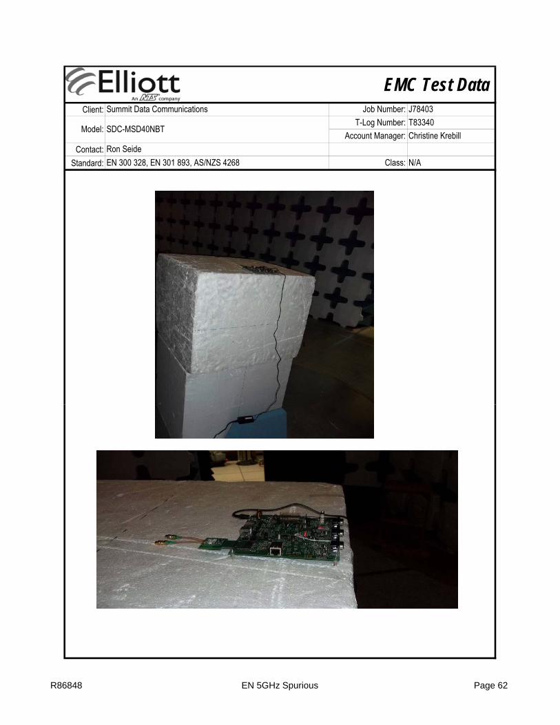
The EUT and all local support equipment were located on the turntable for radiated spurious emissions testing.
The measurement antenna was located 3 meters from the EUT.
Summary of ResultsPass / Fail
Pass
Pass All emissions are more than 10dB below the limit
Run # Test Performed Limit Result / Margin
3 0.0
Frequency Range
2Spurious Emissions
Transmit Mode30 - 12750 MHz
EN 300 328 All emissions are more than 10dB below the limit
4Spurious Emissions
Receive/Stand-By Mode30 - 12750 MHz
EN 300 328
3 3 0.0
Modifications Made During TestingNo modifications were made to the EUT during testing
Deviations From The StandardNo deviations were made from the requirements of the standard.
1 - 12.75 GHz 3
Test Distance Limit Distance Extrapolation Factor25 - 1000 MHz
R86848 EN 2.4GHz Spurious Page 21

EMC Test DataClient:
Contact:Standard:
Summit Data Communications Job Number: J78403
Model: SDC-MSD40NBTT-Log Number: T83340
Account Manager: Christine KrebillRon SeideEN 300 328, EN 301 893, AS/NZS 4268 Class: N/A
Run #1: Radiated Spurious Emissions, Transmit Mode, 25 - 12750 MHz
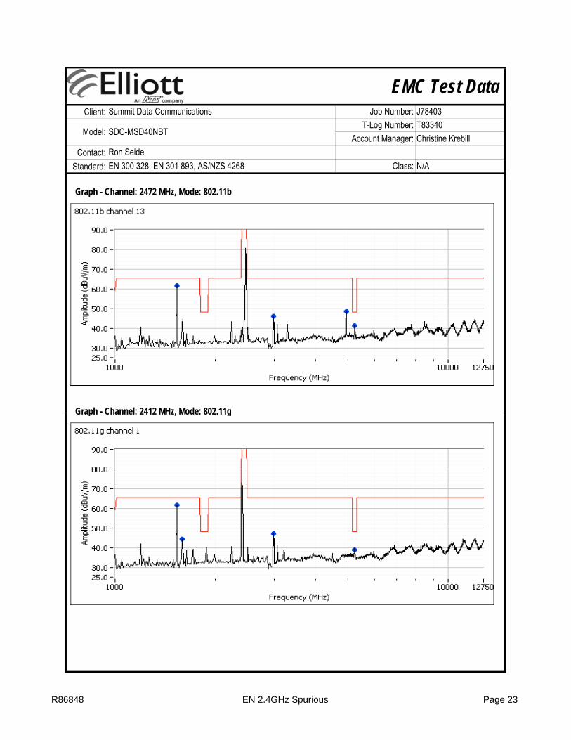
Graph - Channel: 2412 MHz, Mode: 802.11b
R86848 EN 2.4GHz Spurious Page 22
EMC Test DataClient:
Contact:Standard:
Summit Data Communications Job Number: J78403
Model: SDC-MSD40NBTT-Log Number: T83340
Account Manager: Christine KrebillRon SeideEN 300 328, EN 301 893, AS/NZS 4268 Class: N/A
Graph - Channel: 2472 MHz, Mode: 802.11b
Graph - Channel: 2412 MHz Mode: 802 11gGraph Channel: 2412 MHz, Mode: 802.11g
R86848 EN 2.4GHz Spurious Page 23

EMC Test DataClient:
Contact:Standard:
Summit Data Communications Job Number: J78403
Model: SDC-MSD40NBTT-Log Number: T83340
Account Manager: Christine KrebillRon SeideEN 300 328, EN 301 893, AS/NZS 4268 Class: N/A
Graph - Channel: 2472 MHz, Mode: 802.11g
Graph - Channel: 2412 MHz Mode: 802 11n 20MHzGraph Channel: 2412 MHz, Mode: 802.11n 20MHz
R86848 EN 2.4GHz Spurious Page 24

EMC Test DataClient:
Contact:Standard:
Summit Data Communications Job Number: J78403
Model: SDC-MSD40NBTT-Log Number: T83340
Account Manager: Christine KrebillRon SeideEN 300 328, EN 301 893, AS/NZS 4268 Class: N/A
Graph - Channel: 2472 MHz, Mode: 802.11n 20MHz
R86848 EN 2.4GHz Spurious Page 25

EMC Test DataClient:
Contact:Standard:
Summit Data Communications Job Number: J78403
Model: SDC-MSD40NBTT-Log Number: T83340
Account Manager: Christine KrebillRon SeideEN 300 328, EN 301 893, AS/NZS 4268 Class: N/A
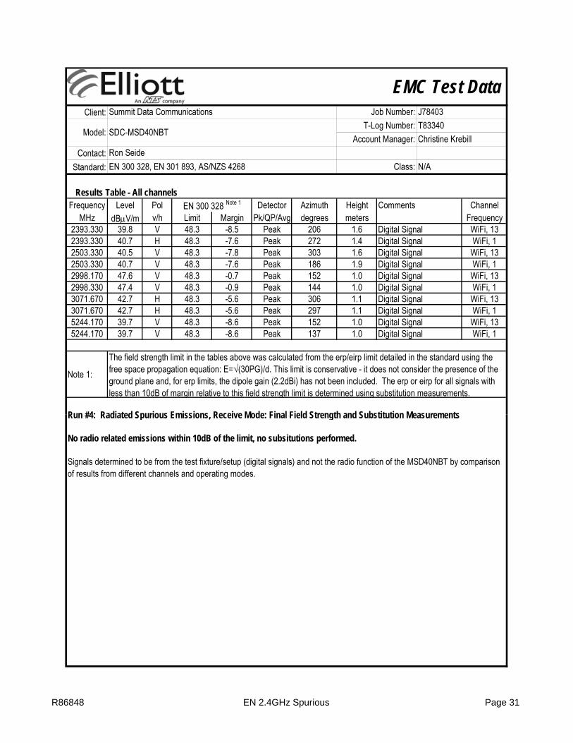
Results Table - All channelsFrequency Level Pol Detector Azimuth Height Comments Channel
MHz dBμV/m v/h Limit Margin Pk/QP/Avg degrees meters and mode153.958 46.1 H 59.3 -13.2 Peak 281 1.5 Digital signal ch 1, b153.958 46.2 H 59.3 -13.1 Peak 280 1.0 Digital signal ch 13, n20198.898 49.6 H 59.3 -9.7 Peak 279 1.0 Digital signal ch 1, b198.898 49.5 H 59.3 -9.8 Peak 274 1.0 Digital signal ch 13, n20241.884 52.5 H 59.3 -6.8 Peak 94 1.0 Digital signal ch 1, b241.884 52.7 H 59.3 -6.6 Peak 110 1.0 Digital signal ch 13, n20286.824 55.2 H 59.3 -4.1 Peak 101 2.0 Digital signal ch 1, b286.824 55.1 H 59.3 -4.2 Peak 95 2.0 Digital signal ch 13, n20329.810 48.9 H 59.3 -10.4 Peak 110 1.5 Digital signal ch 1, b329.810 49.4 H 59.3 -9.9 Peak 110 1.5 Digital signal ch 13, n20
1531.670 61.6 H 65.3 -3.7 Peak 278 1.4 Digital signal ch 13, b1531.670 61.6 H 65.3 -3.7 Peak 292 1.4 Digital signal ch 1, g1531.670 61.4 H 65.3 -3.9 Peak 281 1.4 Digital signal ch 13, g1531.670 63.3 H 65.3 -2.0 Peak 273 1.0 Digital signal ch 1, n201531.670 63.3 H 65.3 -2.0 Peak 274 1.0 Digital signal ch 13, n201586.670 44.2 V 65.3 -21.1 Peak 144 1.3 Digital signal ch 1, g1586 670 46 4 V 65 3 18 9 Peak 128 1 3 Digital signal ch 13 g
EN 300 328 Note 1
1586.670 46.4 V 65.3 -18.9 Peak 128 1.3 Digital signal ch 13, g1595.830 47.1 V 65.3 -18.2 Peak 341 1.0 Digital signal ch 13, n202989.170 47.2 V 65.3 -18.1 Peak 153 1.0 Digital signal ch 1, b2989.170 46.2 V 65.3 -19.1 Peak 154 1.0 Digital signal ch 13, b2989.170 47.2 V 65.3 -18.1 Peak 145 1.0 Digital signal ch 1, g2989.170 46.9 V 65.3 -18.4 Peak 158 1.0 Digital signal ch 13, g2989.170 47.6 V 65.3 -17.7 Peak 152 1.0 Digital signal ch 1, n202989.170 47.1 V 65.3 -18.2 Peak 154 1.0 Digital signal ch 13, n204813.330 50.0 H 65.3 -15.3 Peak 26 1.0 ch 1, b4941.670 48.6 H 65.3 -16.7 Peak 24 1.0 ch 13, b5235.000 39.6 V 48.3 -8.7 Peak 151 1.0 Digital signal ch 13, g5235.000 40.8 V 48.3 -7.5 Peak 160 1.0 Digital signal ch 1, n205241.690 43.6 V 48.3 -4.7 Peak 146 1.0 Digital signal ch 1, b5244.170 41.4 V 48.3 -6.9 Peak 146 1.0 Digital signal ch 13, b5244.170 39.0 V 48.3 -9.3 Peak 152 1.0 Digital signal ch 1, g5244.170 40.4 V 48.3 -7.9 Peak 209 1.6 Digital signal ch 13, n20
Note 1:
The field strength limit in the tables above was calculated from the erp/eirp limit detailed in the standard using the free space propagation equation: E=√(30PG)/d. This limit is conservative - it does not consider the presence of the ground plane and, for erp limits, the dipole gain (2.2dBi) has not been included. The erp or eirp for all signals with less than 10dB of margin relative to this field strength limit is determined using substitution measurements.
R86848 EN 2.4GHz Spurious Page 26

EMC Test DataClient:
Contact:Standard:
Summit Data Communications Job Number: J78403
Model: SDC-MSD40NBTT-Log Number: T83340
Account Manager: Christine KrebillRon SeideEN 300 328, EN 301 893, AS/NZS 4268 Class: N/A
Run #2: Radiated Spurious Emissions, Transmit Mode: Final Field Strength and Substitution Measurements
No radio related emissions within 10dB of the limit, no subsitutions performed.
Signals determined to be from the test fixture/setup (digital signals) and not the radio function of the MSD40NBT by comparison of results from different channels and operating modes.
R86848 EN 2.4GHz Spurious Page 27
EMC Test DataClient:
Contact:Standard:
Summit Data Communications Job Number: J78403
Model: SDC-MSD40NBTT-Log Number: T83340
Account Manager: Christine KrebillRon SeideEN 300 328, EN 301 893, AS/NZS 4268 Class: N/A
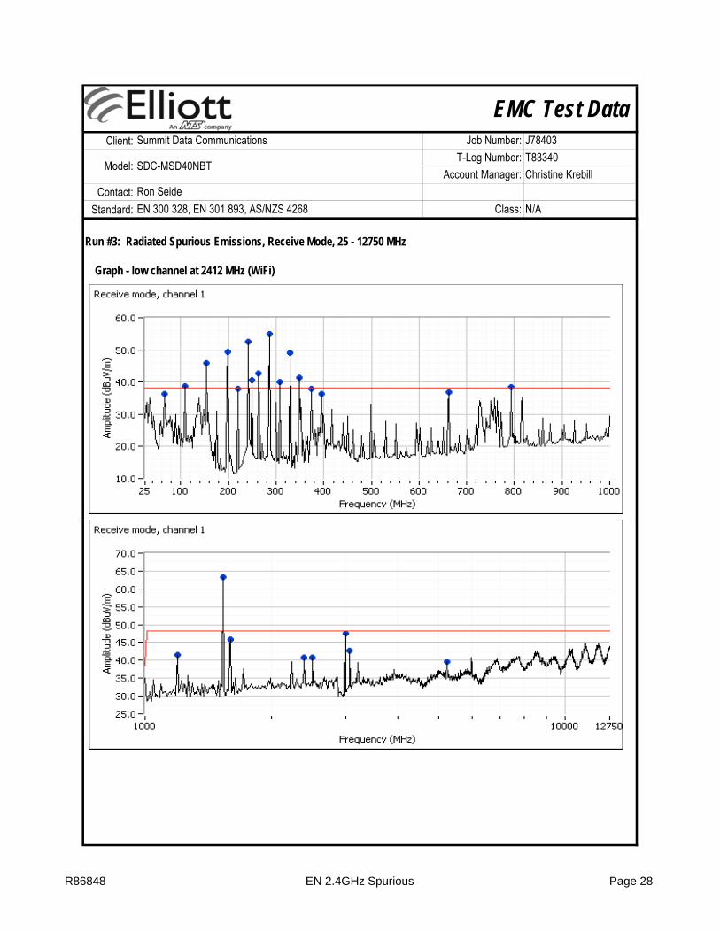
Run #3: Radiated Spurious Emissions, Receive Mode, 25 - 12750 MHz
Graph - low channel at 2412 MHz (WiFi)
R86848 EN 2.4GHz Spurious Page 28

EMC Test DataClient:
Contact:Standard:
Summit Data Communications Job Number: J78403
Model: SDC-MSD40NBTT-Log Number: T83340
Account Manager: Christine KrebillRon SeideEN 300 328, EN 301 893, AS/NZS 4268 Class: N/A
Graph - high channel at 2472 MHz (WiFi)
R86848 EN 2.4GHz Spurious Page 29

EMC Test DataClient:
Contact:Standard:
Summit Data Communications Job Number: J78403
Model: SDC-MSD40NBTT-Log Number: T83340
Account Manager: Christine KrebillRon SeideEN 300 328, EN 301 893, AS/NZS 4268 Class: N/A
Results Table - All channelsFrequency Level Pol Detector Azimuth Height Comments Channel
MHz dBμV/m v/h Limit Margin Pk/QP/Avg degrees meters Frequency34.770 35.0 V 38.3 -3.3 Peak 216 1.0 Digital Signal WiFi, 1366.032 36.4 V 38.3 -1.9 Peak 73 1.0 Digital Signal WiFi, 166.032 36.1 V 38.3 -2.2 Peak 20 1.0 Digital Signal WiFi, 13
109.018 38.8 H 38.3 0.5 Peak 288 1.5 Digital Signal WiFi, 1109.018 39.0 H 38.3 0.7 Peak 288 1.5 Digital Signal WiFi, 13153.958 45.8 H 38.3 7.5 Peak 272 1.5 Digital Signal WiFi, 1153.958 46.1 H 38.3 7.8 Peak 272 1.5 Digital Signal WiFi, 13198.898 49.3 H 38.3 11.0 Peak 285 1.0 Digital Signal WiFi, 1198.898 49.3 H 38.3 11.0 Peak 271 1.0 Digital Signal WiFi, 13220.391 37.9 H 38.3 -0.4 Peak 110 1.0 Digital Signal WiFi, 1220.391 37.9 H 38.3 -0.4 Peak 293 1.0 Digital Signal WiFi, 13241.884 52.5 H 38.3 14.2 Peak 105 1.0 Digital Signal WiFi, 1241.884 52.4 H 38.3 14.1 Peak 95 1.0 Digital Signal WiFi, 13249.699 40.6 H 38.3 2.3 Peak 94 1.0 Digital Signal WiFi, 1249.699 40.8 H 38.3 2.5 Peak 107 1.0 Digital Signal WiFi, 13263.377 42.6 H 38.3 4.3 Peak 273 2.5 Digital Signal WiFi, 1263 377 41 8 H 38 3 3 5 Peak 257 2 5 Digital Signal WiFi 13
EN 300 328 Note 1
263.377 41.8 H 38.3 3.5 Peak 257 2.5 Digital Signal WiFi, 13286.824 54.9 H 38.3 16.6 Peak 109 2.0 Digital Signal WiFi, 1286.824 55.2 H 38.3 16.9 Peak 101 2.0 Digital Signal WiFi, 13308.317 40.0 H 38.3 1.7 Peak 98 2.0 Digital Signal WiFi, 1308.317 40.2 H 38.3 1.9 Peak 106 2.0 Digital Signal WiFi, 13329.810 49.1 H 38.3 10.8 Peak 116 1.5 Digital Signal WiFi, 1329.810 49.2 H 38.3 10.9 Peak 121 1.5 Digital Signal WiFi, 13349.349 41.4 H 38.3 3.1 Peak 100 1.5 Digital Signal WiFi, 1349.349 41.3 H 38.3 3.0 Peak 110 1.5 Digital Signal WiFi, 13374.750 37.9 H 38.3 -0.4 Peak 277 1.5 Digital Signal WiFi, 1374.750 37.2 H 38.3 -1.1 Peak 115 1.5 Digital Signal WiFi, 13396.242 36.4 H 38.3 -1.9 Peak 79 1.5 Digital Signal WiFi, 1661.974 36.8 H 38.3 -1.5 Peak 145 3.0 Digital Signal WiFi, 1661.974 36.2 V 38.3 -2.1 Peak 205 1.0 Digital Signal WiFi, 13792.886 38.4 H 38.3 0.1 Peak 226 1.0 Digital Signal WiFi, 1
1192.500 43.2 V 48.3 -5.1 Peak 181 1.0 Digital Signal WiFi, 131192.500 41.4 V 48.3 -6.9 Peak 144 1.0 Digital Signal WiFi, 11531.670 63.3 H 48.3 15.0 Peak 273 1.0 Digital Signal WiFi, 131531.670 63.3 H 48.3 15.0 Peak 284 1.0 Digital Signal WiFi, 11591.670 43.7 V 48.3 -4.6 Peak 135 1.3 Digital Signal WiFi, 131593.830 45.8 V 48.3 -2.5 Peak 128 1.3 Digital Signal WiFi, 1
R86848 EN 2.4GHz Spurious Page 30
EMC Test DataClient:
Contact:Standard:
Summit Data Communications Job Number: J78403
Model: SDC-MSD40NBTT-Log Number: T83340
Account Manager: Christine KrebillRon SeideEN 300 328, EN 301 893, AS/NZS 4268 Class: N/A
Results Table - All channelsFrequency Level Pol Detector Azimuth Height Comments Channel
MHz dBμV/m v/h Limit Margin Pk/QP/Avg degrees meters Frequency2393.330 39.8 V 48.3 -8.5 Peak 206 1.6 Digital Signal WiFi, 132393.330 40.7 H 48.3 -7.6 Peak 272 1.4 Digital Signal WiFi, 12503.330 40.5 V 48.3 -7.8 Peak 303 1.6 Digital Signal WiFi, 132503.330 40.7 V 48.3 -7.6 Peak 186 1.9 Digital Signal WiFi, 12998.170 47.6 V 48.3 -0.7 Peak 152 1.0 Digital Signal WiFi, 132998.330 47.4 V 48.3 -0.9 Peak 144 1.0 Digital Signal WiFi, 13071.670 42.7 H 48.3 -5.6 Peak 306 1.1 Digital Signal WiFi, 133071.670 42.7 H 48.3 -5.6 Peak 297 1.1 Digital Signal WiFi, 15244.170 39.7 V 48.3 -8.6 Peak 152 1.0 Digital Signal WiFi, 135244.170 39.7 V 48.3 -8.6 Peak 137 1.0 Digital Signal WiFi, 1
Note 1:
Run #4: Radiated Spurious Emissions Receive Mode: Final Field Strength and Substitution Measurements
EN 300 328 Note 1
The field strength limit in the tables above was calculated from the erp/eirp limit detailed in the standard using the free space propagation equation: E=√(30PG)/d. This limit is conservative - it does not consider the presence of the ground plane and, for erp limits, the dipole gain (2.2dBi) has not been included. The erp or eirp for all signals with less than 10dB of margin relative to this field strength limit is determined using substitution measurements.
Run #4: Radiated Spurious Emissions, Receive Mode: Final Field Strength and Substitution Measurements
No radio related emissions within 10dB of the limit, no subsitutions performed.
Signals determined to be from the test fixture/setup (digital signals) and not the radio function of the MSD40NBT by comparison of results from different channels and operating modes.
R86848 EN 2.4GHz Spurious Page 31

EMC Test DataClient:
Contact:Standard:
Summit Data Communications Job Number: J78403
Model: SDC-MSD40NBTT-Log Number: T83340
Account Manager: Christine KrebillRon SeideEN 300 328, EN 301 893, AS/NZS 4268 Class: N/A
R86848 EN 2.4GHz Spurious Page 32

EMC Test DataClient:
Contact:Standard:
Test Specific Details
General Test Configuration
Summary of ResultsResult
Pass
Run # Test Performed Limit Value / Margin
1 Power spectral density at normal conditions
EN 300 32810dBm/MHz
(10 W/MH ) i
802.11b: 8.9 dBm/MHz802.11g: 4.5 dBm/MHz802 11 20 1 5 dB /MH
Test Engineer: M. Birgani / R. Varelas Config Change:EUT Voltage: 3.3 V
The EUT's rf port was connected to the measurement instrument's rf port, via an attenuator or dc-block if necessary.
Radio Performance Test - EN 300 328RF Port Measurements
Objective: The objective of this test session is to perform final qualification testing of the EUT with respect to the specification listed above.
noneTest Location: FT Lab #4
Date of Test: 9/1/2011 & 9/6/11 Config. Used: 1
Ron SeideEN 300 328, EN 301 893, AS/NZS 4268 Class: N/A
Summit Data Communications Job Number: J78403
Model: SDC-MSD40NBTT-Log Number: T83340
Account Manager: Christine Krebill
Pass
Pass
Pass
Pass
Pass3 Receiver spurious emissions, 30MHz - 12,750MHz (rf port) EN 300 328 All emissions below the Rx limit
2 Frequency Range over extreme conditions
AS/NZS 42682400 - 2483.5 MHz
802.11b: 2405.64 - 2478.22 MHz802.11g: 2403.44 - 2480.60 MHz802.11n20: 2402.98-2481.12 MHz
3 Transmitter spurious emissions, 30MHz - 12,750MHz (rf port) EN 300 328 All emissions below the Tx limit
2 Output Power over extreme conditions
EN 300 328,20dBm (100mW) eirp
802.11b: 19.3 dBm802.11g: 15.3 dBm802.11n20: 12.7 dBm
2 Frequency Range over extreme conditions
EN 300 3282400 - 2483.5 MHz
802.11b: 2403.80 - 2403.25 MHz802.11g: 2403.03 - 2481.07 MHz802.11n20: 2402.88- 2481.35 MHz
(10mW/MHz) eirp 802.11n20: 1.5 dBm/MHz
R86848 WiFi - 2.4GHz RF Port Page 33

EMC Test DataClient:
Contact:Standard:
Ron SeideEN 300 328, EN 301 893, AS/NZS 4268 Class: N/A
Summit Data Communications Job Number: J78403
Model: SDC-MSD40NBTT-Log Number: T83340
Account Manager: Christine Krebill
X
X
Ambient (Normal) Conditions: Temperature: 20 °CRel Humidity: 32 %
Temperature extremes:-20°C to +55°C (Limits for unrestricted use taken from EN 300 328 / EN 300 220) 0°C to +35°C (Limits for indoor use taken from EN 300 328 / EN 300 220)-10°C to +55°C (taken from AS/NZS 4268)Manufacturer declared values: ??°C to ??°C
Deviations From The StandardNo deviations were made from the requirements of the standard.
Normal and Extreme Operating Conditions:Test NotesVoltage extremes (nominal/normal voltage defined as 3.3 V):
Voltage extremes for DC-powered equipment +/10% of nominal
Modifications Made During TestingNo modifications were made to the EUT during testing
Rel. Humidity: 32 %
Run #1: Power Measurements - Spread spectrum (Digital Modulation)
8021.11b 8021.11gRate Setting Pmeas Duty Cycle Pout Rate Setting Pmeas Duty Cycle Pout
1 Default 15.4 1 15.4 6 Default 11.4 1 11.42 Default 15.4 1 15.4 9 Default 11.7 1 11.7
5.5 Default 15.4 1 15.4 12 Default 11.7 1 11.711 Default 15.1 1 15.1 18 Default 11.3 1 11.3
24 Default 11.3 1 11.3Setting: software power setting of EUT 36 Default 11.1 1 11.1Pmeas: Measured output power (average) 48 Default 10.6 1 10.6Duty Cycle: Duty cycle of transmissions (1 = 100%) 54 Default 8.6 1 8.6
Initial measurements made on the center channel to determine the data rate with the highest output power. All final measurements made with device operating at the highest power level.
R86848 WiFi - 2.4GHz RF Port Page 34

EMC Test DataClient:
Contact:Standard:
Ron SeideEN 300 328, EN 301 893, AS/NZS 4268 Class: N/A
Summit Data Communications Job Number: J78403
Model: SDC-MSD40NBTT-Log Number: T83340
Account Manager: Christine Krebill
Run #1: Power Measurements - Spread spectrum (Digital Modulation)
0.6 dB Attenuator: 10.0 dB Total Loss: 17.5 dB0.8 dB Combiner: 6.1 dB
Note 1:
Note 2:
Note 3:
Note 4:
Note 5:
Normal Extreme
Duty Cycle - the duty cycle of the transmitter during the power measurement [time on /(time off + time on)]. Measured using diode detector and oscilloscope or directly from the analyzer.EIRP levels are the measured levels corrected for duty cycle [10log(duty cycle)] and EUT antenna gain. For MIMO modes the total power is the aggregated eirp for each transmit chain.
Average Power1 under normal and extreme operating conditions
Power Channel / Average Power (dBm)1 For Operating Condition Max Max
Average Maximum permitted
Cable Loss:Cable Loss:
Notes for power and power spectral density measurementsAverage Power measured using a wideband, calibrated RF power meter with a thermocouple detector (or an equivalent thereof).PSD measured using a thermocouple detector (or an equivalent thereof) connected to the IF output of the spectrum analyzer, with the analyzer set to RMS Avg detector with RB=VB= 1MHz for digital modulation and RB=VB= 100kHz for FHSS.Gain is the maximum gain of the antenna assembly that can be used with the EUT at this power level.
Normal20°C3.3 V 3.0 V 3.6 V 3.0 V 3.6 V
Default #1b 14.9 14.3 14.3 15.3 15.3 3.0 1.0 18.3 20.0Default #6b 15.4 14.9 14.9 15.0 15.0 3.0 1.0 18.4 20.0Default #13b 16.3 16.2 16.3 16.3 16.3 3.0 1.0 19.3 20.0Default #1g 10.7 9.6 9.6 10.9 10.9 3.0 1.0 13.9 20.0Default #6g 11.4 11.0 11.0 11.1 11.1 3.0 1.0 14.4 20.0Default #13g 12.1 12.3 12.3 12.3 12.3 3.0 1.0 15.3 20.0Default #1n20 7.9 5.5 5.5 8.0 8.1 3.0 1.0 11.1 20.0Default #6n20 8.6 7.1 7.1 8.5 8.5 3.0 1.0 11.6 20.0Default #13n20 9.7 8.6 8.6 9.5 9.7 3.0 1.0 12.7 20.0
Extreme-20°C 55°C
Power Setting
Channel / Mode
Antenna Gain3
Duty Cycle4 Average Power (EIRP)5
permitted EIRP (dBm)
R86848 WiFi - 2.4GHz RF Port Page 35

EMC Test DataClient:
Contact:Standard:
Ron SeideEN 300 328, EN 301 893, AS/NZS 4268 Class: N/A
Summit Data Communications Job Number: J78403
Model: SDC-MSD40NBTT-Log Number: T83340
Account Manager: Christine Krebill
PSD2 Gain3 Duty EIRP5
dBm dBi Cycle4 PSD Limit MarginDefault #1b 4.9 3.0 1.0 7.9 10.0 -2.1Default #6b 4.6 3.0 1.0 7.6 10.0 -2.4Default #13b 5.9 3.0 1.0 8.9 10.0 -1.1Default #1g -0.6 3.0 1.0 2.4 10.0 -7.6Default #6g 0.8 3.0 1.0 3.8 10.0 -6.2Default #13g 1.5 3.0 1.0 4.5 10.0 -5.5Default #1n20 -3.8 3.0 1.0 -0.8 10.0 -10.8Default #6n20 -2.2 3.0 1.0 0.8 10.0 -9.2Default #13n20 -1.5 3.0 1.0 1.5 10.0 -8.5
Run #2: Frequency Range Under Normal and Extreme Conditions - EN 300 328
Normal20°C
Measured Frequency (MHz) For Operating ConditionLow FL
High FHResultExtreme
-20°C 55°C
2413.2822438.0902473.020
Mode Antenna Gain
Power Setting
2412.8052436.1222471.1412413.2332438.0822470.337
Power spectral Density2 (normal operating conditions)Power Setting Channel
Frequency PSDMHz
3.3 V 3.0 V 3.6 V 3.0 V 3.6 VFL (MHz) b 3.0 Default 2403.87 2403.80 2403.90 2404.000 2404.030 2403.80 PASSFH (MHz) b 3.0 Default 2480.12 2480.18 2480.25 2480.07 2479.91 2480.25 PASSFL (MHz) g 3.0 Default 2403.25 2403.03 2403.07 2403.41 2403.20 2403.03 PASSFH (MHz) g 3.0 Default 2480.63 2481.07 2481.07 2480.94 2480.96 2481.07 PASSFL (MHz) n20 3.0 Default 2402.88 2402.93 2402.90 2402.88 2402.99 2402.88 PASSFH (MHz) n20 3.0 Default 2481.17 2481.35 2481.32 2481.15 2481.17 2481.35 PASS
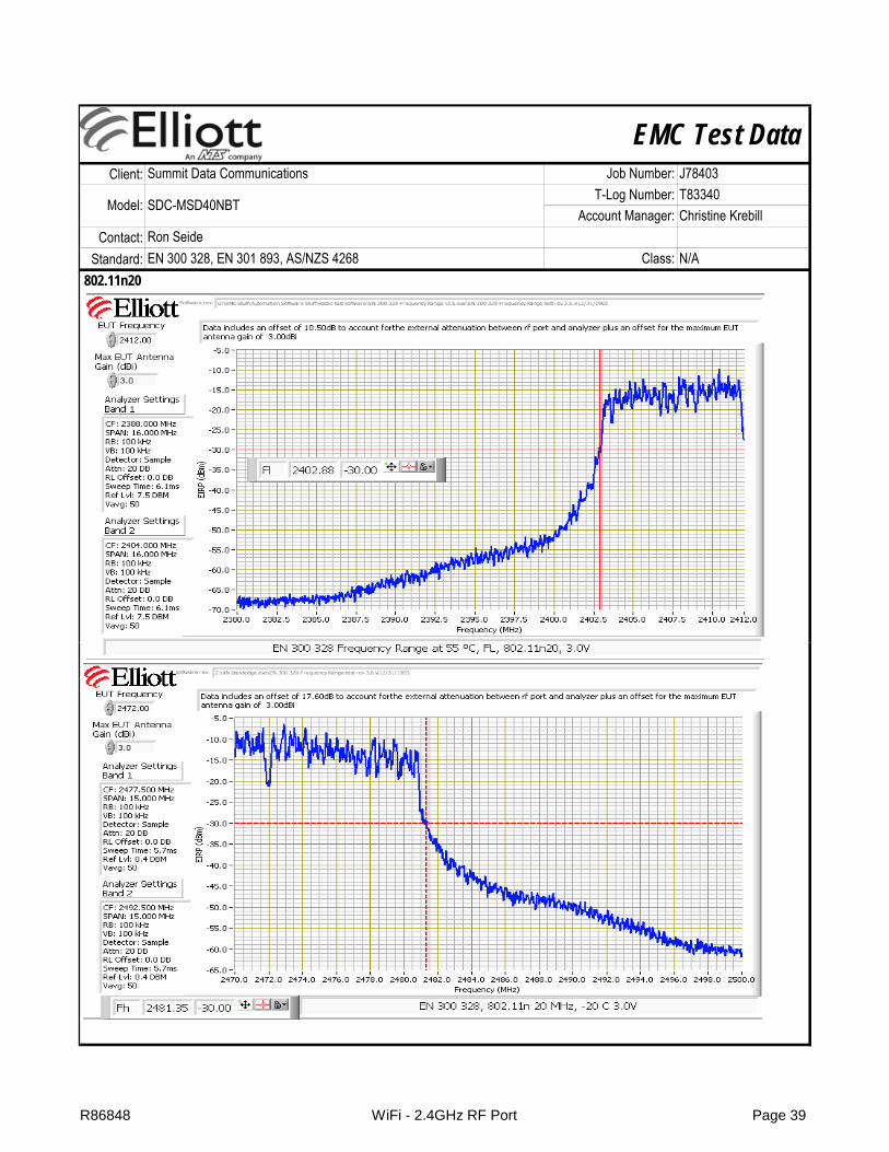
FL and Fh are the lowest and highest frequencies above the spurious emission limit of -30dBm/100kHz eirp for the operating mode (data rate and modulation) that produced the widest frequency range.If the device meets the frequency range requirements at the highest power setting and with the highest gain antenna then no further tests are required. If it does not then tests are made for each power setting using the highest gain that can be used with each power setting.
R86848 WiFi - 2.4GHz RF Port Page 36

EMC Test DataClient:
Contact:Standard:
Ron SeideEN 300 328, EN 301 893, AS/NZS 4268 Class: N/A
Summit Data Communications Job Number: J78403
Model: SDC-MSD40NBTT-Log Number: T83340
Account Manager: Christine Krebill
802.11b
R86848 WiFi - 2.4GHz RF Port Page 37

EMC Test DataClient:
Contact:Standard:
Ron SeideEN 300 328, EN 301 893, AS/NZS 4268 Class: N/A
Summit Data Communications Job Number: J78403
Model: SDC-MSD40NBTT-Log Number: T83340
Account Manager: Christine Krebill
802.11g
R86848 WiFi - 2.4GHz RF Port Page 38
EMC Test DataClient:
Contact:Standard:
Ron SeideEN 300 328, EN 301 893, AS/NZS 4268 Class: N/A
Summit Data Communications Job Number: J78403
Model: SDC-MSD40NBTT-Log Number: T83340
Account Manager: Christine Krebill
802.11n20
R86848 WiFi - 2.4GHz RF Port Page 39

EMC Test DataClient:
Contact:Standard:
Ron SeideEN 300 328, EN 301 893, AS/NZS 4268 Class: N/A
Summit Data Communications Job Number: J78403
Model: SDC-MSD40NBTT-Log Number: T83340
Account Manager: Christine Krebill
Run #2: Frequency Range Under Normal and Extreme Conditions - 2400 - 2483.5MHz, AZ/NZS 4268
Normal20°C3.3 V 3.0 V 3.6 V 3.0 V 3.6 V
FL (MHz) b 3.0 Default 2405.644 2405.720 2405.720 2405.711 2405.711 2405.644 PASSFH (MHz) b 3.0 Default 2478.156 2478.160 2478.160 2478.223 2478.223 2478.223 PASSFL (MHz) g 3.0 Default 2403.514 2403.480 2403.480 2403.448 2403.448 2403.448 PASSFH (MHz) g 3.0 Default 2480.552 2480.520 2480.600 2463.381 2480.552 2480.600 PASSFL (MHz) n20 3.0 Default 2403.048 2403.040 2403.040 2402.982 2402.982 2402.982 PASSFH (MHz) n20 3.0 Default 2481.085 2481.120 2481.080 2481.110 2481.110 2481.120 PASS
-20°C 55°C
FL and FH are the frequencies the define the upper and lower limits of the 99% signal bandwidth. FL is taken from the 99% bandwidth plot for the lowest operating frequency and FH from the 99% bandwidth plot for the highest operating frequency.
Mode Antenna Gain
Power Setting
Measured Frequency (MHz) For Operating ConditionLow FL
High FHResultExtreme
R86848 WiFi - 2.4GHz RF Port Page 40

EMC Test DataClient:
Contact:Standard:
Ron SeideEN 300 328, EN 301 893, AS/NZS 4268 Class: N/A
Summit Data Communications Job Number: J78403
Model: SDC-MSD40NBTT-Log Number: T83340
Account Manager: Christine Krebill
802.11b
R86848 WiFi - 2.4GHz RF Port Page 41

EMC Test DataClient:
Contact:Standard:
Ron SeideEN 300 328, EN 301 893, AS/NZS 4268 Class: N/A
Summit Data Communications Job Number: J78403
Model: SDC-MSD40NBTT-Log Number: T83340
Account Manager: Christine Krebill
802.11g
R86848 WiFi - 2.4GHz RF Port Page 42

EMC Test DataClient:
Contact:Standard:
Ron SeideEN 300 328, EN 301 893, AS/NZS 4268 Class: N/A
Summit Data Communications Job Number: J78403
Model: SDC-MSD40NBTT-Log Number: T83340
Account Manager: Christine Krebill
802.11n20
R86848 WiFi - 2.4GHz RF Port Page 43

EMC Test DataClient:
Contact:Standard:
Ron SeideEN 300 328, EN 301 893, AS/NZS 4268 Class: N/A
Summit Data Communications Job Number: J78403
Model: SDC-MSD40NBTT-Log Number: T83340
Account Manager: Christine Krebill
Run #3: Antenna Port Conducted Spurious Emissions, Transmit Mode, 30 - 12750 MHz
R86848 WiFi - 2.4GHz RF Port Page 44

EMC Test DataClient:
Contact:Standard:
Ron SeideEN 300 328, EN 301 893, AS/NZS 4268 Class: N/A
Summit Data Communications Job Number: J78403
Model: SDC-MSD40NBTT-Log Number: T83340
Account Manager: Christine Krebill
R86848 WiFi - 2.4GHz RF Port Page 45

EMC Test DataClient:
Contact:Standard:
Ron SeideEN 300 328, EN 301 893, AS/NZS 4268 Class: N/A
Summit Data Communications Job Number: J78403
Model: SDC-MSD40NBTT-Log Number: T83340
Account Manager: Christine Krebill
R86848 WiFi - 2.4GHz RF Port Page 46

EMC Test DataClient:
Contact:Standard:
Ron SeideEN 300 328, EN 301 893, AS/NZS 4268 Class: N/A
Summit Data Communications Job Number: J78403
Model: SDC-MSD40NBTT-Log Number: T83340
Account Manager: Christine Krebill
Frequency Level Port Detector Channel Mode CommentsMHz dBm Limit Margin
4946.320 -63.6 RF Port -30.0 -33.6 Peak 13 n204823.270 -59.6 RF Port -30.0 -29.6 Peak 1 n20451.120 -60.6 RF Port -36.0 -24.6 Peak 1 b
4823.270 -41.9 RF Port -30.0 -11.9 Peak 1 b511.280 -59.2 RF Port -36.0 -23.2 Peak 13 b
4943.310 -46.1 RF Port -30.0 -16.1 Peak 13 b4943.310 -59.2 RF Port -30.0 -29.2 Peak 13 g4823.270 -57.6 RF Port -30.0 -27.6 Peak 1 g
EN 300 328
R86848 WiFi - 2.4GHz RF Port Page 47

EMC Test DataClient:
Contact:Standard:
Ron SeideEN 300 328, EN 301 893, AS/NZS 4268 Class: N/A
Summit Data Communications Job Number: J78403
Model: SDC-MSD40NBTT-Log Number: T83340
Account Manager: Christine Krebill
Run #4: Antenna Port Conducted Spurious Emissions, Receive Mode, 30 - 12,750 MHz
R86848 WiFi - 2.4GHz RF Port Page 48

EMC Test DataClient:
Contact:Standard:
Test Specific Details
General Test Configuration
Ambient Conditions: Temperature: 20-22 °CRel. Humidity: 36 %
Summit Data Communications Job Number: J78403
Model: SDC-MSD40NBTT-Log Number: T83340
Account Manager: Christine KrebillRon SeideEN 300 328, EN 301 893, AS/NZS 4268 Class: N/A
Radiated Spurious EmissionsEN 301 893-1 v1.5.1, AS/NZS 4268: 2008
Objective: The objective of this test session is to perform final qualification testing of the EUT with respect to the specification listed above.
Date of Test: Jan 10/12 Config. Used: 1Test Engineer: John Caizzi / R. Varelas Config Change: noneTest Location: FT4 EUT Host Voltage: 230V / 50Hz
The EUT and all local support equipment were located on the turntable for radiated spurious emissions testing. The EUT was 1.5m above the ground plane.
The measurement antenna was located 3 meters from the EUT.
Summary of ResultsPass / Fail
Pass
PassSpurious Emissions
Receive/Stand-By Mode, 30 - 26000 MHz
EN 301 893 -50.9dBm @ 3453.5MHz (-3.9dB)
Run # Test Performed Limit Result / Margin
Modifications Made During TestingNo modifications were made to the EUT during testing
Deviations From The StandardNo deviations were made from the requirements of the standard.
2 Spurious Emissions Transmit Mode, 30 - 26000 MHz EN 301 893 -38.9dBm @ 1536.8MHz (-8.9dB)
4
R86848 EN 5GHz Spurious Page 49

EMC Test DataClient:
Contact:Standard:
Summit Data Communications Job Number: J78403
Model: SDC-MSD40NBTT-Log Number: T83340
Account Manager: Christine KrebillRon SeideEN 300 328, EN 301 893, AS/NZS 4268 Class: N/A
Run #1: Radiated Spurious Emissions, Transmit Mode, 30 - 26000 MHz
Channel: 5180 MHz, Mode: 802.11n20
R86848 EN 5GHz Spurious Page 50

EMC Test DataClient:
Contact:Standard:
Summit Data Communications Job Number: J78403
Model: SDC-MSD40NBTT-Log Number: T83340
Account Manager: Christine KrebillRon SeideEN 300 328, EN 301 893, AS/NZS 4268 Class: N/A
Channel: 5320 MHz, Mode: 802.11n20
Channel: 5500 MHz Mode: 802 11n20Channel: 5500 MHz, Mode: 802.11n20
R86848 EN 5GHz Spurious Page 51

EMC Test DataClient:
Contact:Standard:
Summit Data Communications Job Number: J78403
Model: SDC-MSD40NBTT-Log Number: T83340
Account Manager: Christine KrebillRon SeideEN 300 328, EN 301 893, AS/NZS 4268 Class: N/A
Graph - Channel: 5700 MHz, Mode: 802.11n20
R86848 EN 5GHz Spurious Page 52

EMC Test DataClient:
Contact:Standard:
Summit Data Communications Job Number: J78403
Model: SDC-MSD40NBTT-Log Number: T83340
Account Manager: Christine KrebillRon SeideEN 300 328, EN 301 893, AS/NZS 4268 Class: N/A
Results Table - All channelsFrequency Level Pol Detector Azimuth Height Comments Channel
MHz dBμV/m v/h Limit Margin Pk/QP/Avg degrees meters and mode66.032 35.5 V 41.3 -5.8 Peak 16 1.5 note 2 36
109.018 46.8 H 41.3 5.5 Peak 270 1.5 note 2 36153.958 57.0 H 59.3 -2.3 Peak 270 1.0 note 2 36175.451 43.6 H 41.3 2.3 Peak 260 1.0 note 2 36198.898 64.1 H 41.3 22.8 Peak 265 1.0 note 2 36220.391 56.3 H 41.3 15.0 Peak 260 1.0 note 2 36241.884 68.0 H 59.3 8.7 Peak 54 2.5 note 2 36249.699 52.9 H 59.3 -6.4 Peak 259 2.5 note 2 36263.377 52.2 H 59.3 -7.1 Peak 260 2.0 note 2 36286.824 57.4 H 59.3 -1.9 Peak 260 2.0 note 2 36595.541 31.7 H 41.3 -9.6 Peak 142 1.5 note 2 36661.974 33.5 V 41.3 -7.8 Peak 43 2.0 note 2 36749.900 33.8 H 41.3 -7.5 Peak 342 3.0 note 2 36816.333 36.0 H 41.3 -5.3 Peak 270 1.5 note 2 36
1531.670 60.5 H 65.3 -4.8 Peak 59 1.0 361536.840 60.7 H 65.3 -4.6 PK 60 1.0 RBW = 1 MHz = VBw 362989 170 48 3 V 65 3 17 0 Peak 147 1 3 36
EN 301 893 Note 1
2989.170 48.3 V 65.3 -17.0 Peak 147 1.3 363447.500 47.2 H 65.3 -18.1 Peak 46 1.0 36
1531.670 59.7 H 65.3 -5.6 Peak 24 1.6 641536.740 59.2 H 65.3 -6.1 Vavg 27 1.5 RBW = 1 MHz = VBw 642989.170 48.0 V 65.3 -17.3 Peak 140 1.3 643548.330 46.4 H 65.3 -18.9 Peak 39 1.3 64
1880.000 46.8 V 65.3 -18.5 Peak 140 1.9 1002237.500 43.1 V 65.3 -22.2 Peak 141 2.2 100
66.032 35.4 V 41.3 -5.9 Peak 17 1.5 note 2 140109.018 47.3 H 41.3 6.0 Peak 265 1.5 note 2 140153.958 57.1 H 59.3 -2.2 Peak 270 1.0 note 2 140175.451 44.2 H 41.3 2.9 Peak 260 1.0 note 2 140198.898 65.1 H 41.3 23.8 Peak 264 1.0 note 2 140220.391 57.2 H 41.3 15.9 Peak 275 1.0 note 2 140241.884 68.0 H 59.3 8.7 Peak 43 2.5 note 2 140249.699 53.5 H 59.3 -5.8 Peak 251 2.5 note 2 140263.377 52.4 H 59.3 -6.9 Peak 235 2.0 note 2 140286.824 58.4 H 59.3 -0.9 Peak 260 2.0 note 2 140
R86848 EN 5GHz Spurious Page 53

EMC Test DataClient:
Contact:Standard:
Summit Data Communications Job Number: J78403
Model: SDC-MSD40NBTT-Log Number: T83340
Account Manager: Christine KrebillRon SeideEN 300 328, EN 301 893, AS/NZS 4268 Class: N/A
Results Table - All channelsFrequency Level Pol Detector Azimuth Height Comments Channel
MHz dBμV/m v/h Limit Margin Pk/QP/Avg degrees meters and mode595.541 26.5 H 41.3 -14.8 Peak 326 1.5 note 2 140661.974 35.8 H 41.3 -5.5 Peak 343 3.0 note 2 140749.900 33.6 H 41.3 -7.7 Peak 338 3.0 note 2 140816.333 35.2 H 41.3 -6.1 Peak 255 2.0 note 2 140
2237.500 40.4 V 65.3 -24.9 Peak 328 1.6 1402503.330 40.4 V 65.3 -24.9 Peak 285 1.9 1403795.830 44.3 V 65.3 -21.0 Peak 10 1.0 140
Note 1:
Note 2:
EN 301 893 Note 1
The EUT was evaluated 30-1000MHz at two different channels to demonstrate that the emissions are the same regardless of channel selection. All emissions remained the same when a different channel was selected.
The field strength limit in the tables above was calculated from the erp/eirp limit detailed in the standard using the free space propagation equation: E=√(30PG)/d. This limit is conservative - it does not consider the presence of the ground plane and, for erp limits, the dipole gain (2.2dBi) has not been included. The erp or eirp for all signals with less than 10dB of margin relative to this field strength limit is determined using substitution measurements.
R86848 EN 5GHz Spurious Page 54
EMC Test DataClient:
Contact:Standard:
Summit Data Communications Job Number: J78403
Model: SDC-MSD40NBTT-Log Number: T83340
Account Manager: Christine KrebillRon SeideEN 300 328, EN 301 893, AS/NZS 4268 Class: N/A
Run #2: Radiated Spurious Emissions, Transmit Mode: Final Field Strength and Substitution Measurements
Frequency Level Pol Detector Azimuth Height Comments ChannelMHz dBμV/m v/h Limit Margin Pk/QP/Avg degrees meters and mode
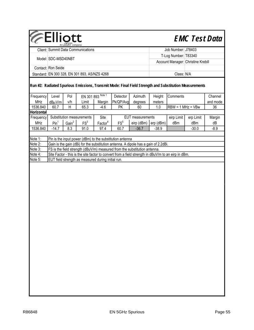
1536.840 60.7 H 65.3 -4.6 PK 60 1.0 RBW = 1 MHz = VBw 36HorizontalFrequency Site eirp Limit erp Limit Margin
MHz Pin1 Gain2 FS3 Factor4 FS5 eirp (dBm) erp (dBm) dBm dBm dB1536.840 -14.7 8.3 91.0 97.4 60.7 -36.7 -38.9 -30.0 -8.9
Note 1:Note 2:Note 3:Note 4:Note 5:
EN 301 893 Note 1
Substitution measurements EUT measurements
Pin is the input power (dBm) to the substitution antennaGain is the gain (dBi) for the substitution antenna. A dipole has a gain of 2.2dBi.FS is the field strength (dBuV/m) measured from the substitution antenna.Site Factor - this is the site factor to convert from a field strength in dBuV/m to an eirp in dBm.EUT field strength as measured during initial run.
R86848 EN 5GHz Spurious Page 55

EMC Test DataClient:
Contact:Standard:
Summit Data Communications Job Number: J78403
Model: SDC-MSD40NBTT-Log Number: T83340
Account Manager: Christine KrebillRon SeideEN 300 328, EN 301 893, AS/NZS 4268 Class: N/A
Run #3: Radiated Spurious Emissions, Receive Mode, 25 - 26000 MHz
Graph - low channel at 5180 MHz
R86848 EN 5GHz Spurious Page 56

EMC Test DataClient:
Contact:Standard:
Summit Data Communications Job Number: J78403
Model: SDC-MSD40NBTT-Log Number: T83340
Account Manager: Christine KrebillRon SeideEN 300 328, EN 301 893, AS/NZS 4268 Class: N/A
Graph - high channel at 5320 MHz
Graph - low channel at 5500 MHzGraph low channel at 5500 MHz
R86848 EN 5GHz Spurious Page 57

EMC Test DataClient:
Contact:Standard:
Summit Data Communications Job Number: J78403
Model: SDC-MSD40NBTT-Log Number: T83340
Account Manager: Christine KrebillRon SeideEN 300 328, EN 301 893, AS/NZS 4268 Class: N/A
Graph - high channel at 5700 MHz
R86848 EN 5GHz Spurious Page 58

EMC Test DataClient:
Contact:Standard:
Summit Data Communications Job Number: J78403
Model: SDC-MSD40NBTT-Log Number: T83340
Account Manager: Christine KrebillRon SeideEN 300 328, EN 301 893, AS/NZS 4268 Class: N/A
Results Table - All channelsFrequency Level Pol Detector Azimuth Height Comments Channel
MHz dBμV/m v/h Limit Margin Pk/QP/Avg degrees meters Frequency66.032 34.8 V 38.3 -3.5 Peak 44 1.5 note 2 36
109.018 47.0 H 38.3 8.7 Peak 265 1.5 note 2 36153.958 56.6 H 38.3 18.3 Peak 270 1.0 note 2 36175.451 43.6 H 38.3 5.3 Peak 260 1.0 note 2 36198.898 64.4 H 38.3 26.1 Peak 270 1.0 note 2 36220.391 56.7 H 38.3 18.4 Peak 276 1.0 note 2 36241.884 68.0 H 38.3 29.7 Peak 54 2.5 note 2 36249.699 52.9 H 38.3 14.6 Peak 261 2.5 note 2 36263.377 53.7 H 38.3 15.4 Peak 84 2.0 note 2 36286.824 57.8 H 38.3 19.5 Peak 260 2.0 note 2 36329.810 41.6 H 38.3 3.3 Peak 260 1.5 note 2 36661.974 36.5 H 38.3 -1.8 Peak 316 2.0 note 2 36792.886 39.3 H 38.3 1.0 Peak 337 2.0 note 2 36
3453.540 44.7 H 48.3 -3.6 PK 2 1.6 RB 1 MHz;VB 3 MHz;Pk 361905.820 40.1 V 48.3 -8.2 PK 107 1.8 RB 1 MHz;VB 3 MHz;Pk 362245.600 38.9 V 48.3 -9.4 PK 260 1.9 RB 1 MHz;VB 3 MHz;Pk 36
EN 301 893 Note 1
2245.970 41.1 V 48.3 -7.2 PK 280 2.0 RB 1 MHz;VB 3 MHz;Pk 642511.080 42.0 V 48.3 -6.3 PK 277 1.7 RB 1 MHz;VB 3 MHz;Pk 643453.320 44.6 H 48.3 -3.7 PK 10 1.6 RB 1 MHz;VB 3 MHz;Pk 64
3453.350 44.6 H 48.3 -3.7 PK 1 1.5 RB 1 MHz;VB 3 MHz;Pk 1002516.200 39.1 V 48.3 -9.2 PK 178 1.7 RB 1 MHz;VB 3 MHz;Pk 1002245.460 42.4 V 48.3 -5.9 PK 303 1.7 RB 1 MHz;VB 3 MHz;Pk 100
66.032 34.7 V 38.3 -3.6 Peak 23 2.0 note 2 140109.018 46.9 H 38.3 8.6 Peak 259 1.5 note 2 140153.958 56.7 H 38.3 18.4 Peak 270 1.0 note 2 140175.451 43.8 H 38.3 5.5 Peak 260 1.0 note 2 140198.898 64.4 H 38.3 26.1 Peak 275 1.0 note 2 140220.391 56.8 H 38.3 18.5 Peak 270 1.0 note 2 140241.884 68.0 H 38.3 29.7 Peak 49 2.5 note 2 140249.699 53.0 H 38.3 14.7 Peak 250 2.5 note 2 140263.377 54.0 H 38.3 15.7 Peak 85 1.0 note 2 140286.824 57.8 H 38.3 19.5 Peak 260 2.0 note 2 140329.810 41.7 H 38.3 3.4 Peak 259 1.5 note 2 140661.974 35.2 H 38.3 -3.1 Peak 348 3.0 note 2 140
R86848 EN 5GHz Spurious Page 59

EMC Test DataClient:
Contact:Standard:
Summit Data Communications Job Number: J78403
Model: SDC-MSD40NBTT-Log Number: T83340
Account Manager: Christine KrebillRon SeideEN 300 328, EN 301 893, AS/NZS 4268 Class: N/A
Results Table - All channelsFrequency Level Pol Detector Azimuth Height Comments Channel
MHz dBμV/m v/h Limit Margin Pk/QP/Avg degrees meters Frequency792.886 35.1 H 38.3 -3.2 Peak 255 1.0 note 2 140
1190.370 46.0 V 48.3 -2.3 PK 296 2.1 RB 1 MHz;VB 3 MHz;Pk 1402510.330 41.4 V 48.3 -6.9 PK 314 1.8 RB 1 MHz;VB 3 MHz;Pk 1403453.480 44.0 H 48.3 -4.3 PK 2 1.7 RB 1 MHz;VB 3 MHz;Pk 140
Note 1:
Note 2:
EN 301 893 Note 1
The field strength limit in the tables above was calculated from the erp/eirp limit detailed in the standard using the free space propagation equation: E=√(30PG)/d. This limit is conservative - it does not consider the presence of the ground plane and, for erp limits, the dipole gain (2.2dBi) has not been included. The erp or eirp for all signals with less than 10dB of margin relative to this field strength limit is determined using substitution measurements.The EUT was evaluated 30-1000MHz at two different channels to demonstrate that the emissions are the same regardless of channel selection. All emissions remained the same when a different channel was selected.
R86848 EN 5GHz Spurious Page 60

EMC Test DataClient:
Contact:Standard:
Summit Data Communications Job Number: J78403
Model: SDC-MSD40NBTT-Log Number: T83340
Account Manager: Christine KrebillRon SeideEN 300 328, EN 301 893, AS/NZS 4268 Class: N/A
Run #4: Radiated Spurious Emissions, Receive Mode: Final Field Strength and Substitution Measurements
Frequency Level Pol Detector Azimuth Height Comments ChannelMHz dBμV/m v/h Limit Margin Pk/QP/Avg degrees meters Frequency
1190.370 46.0 V 48.3 -2.3 PK 296 2.1 RB 1 MHz;VB 3 MHz;Pk 1401905.820 40.1 V 48.3 -8.2 PK 107 1.8 RB 1 MHz;VB 3 MHz;Pk 362245.460 42.4 V 48.3 -5.9 PK 303 1.7 RB 1 MHz;VB 3 MHz;Pk 1002511.080 42.0 V 48.3 -6.3 PK 277 1.7 RB 1 MHz;VB 3 MHz;Pk 643453.540 44.7 H 48.3 -3.6 PK 2 1.6 RB 1 MHz;VB 3 MHz;Pk 36
HorizontalFrequency Site eirp Limit erp Limit Margin
MHz Pin1 Gain2 FS3 Factor4 FS5 eirp (dBm) erp (dBm) dBm dBm dB3453.540 -17.5 9.1 85.0 93.4 44.7 -48.7 -50.9 -47.0 -3.9
VerticalFrequency Site eirp Limit erp Limit Margin
MHz Pin1 Gain2 FS3 Factor4 FS5 eirp (dBm) erp (dBm) dBm dBm dB1190.370 -14.1 6.2 90.2 98.1 46.0 -52.1 -54.3 -47.0 -7.31905.820 -15.4 7.9 89.2 96.7 40.1 -56.6 -58.8 -47.0 -11.82245.460 -16.2 9.3 90.0 96.9 42.4 -54.5 -56.7 -47.0 -9.7
Substitution measurements EUT measurements
EN 301 893 Note 1
Substitution measurements EUT measurements
2511.080 -16.5 9.1 88.7 96.1 42.0 -54.1 -56.3 -47.0 -9.3
Note 1:
Note 2:
Note 3:
Note 4:Note 5: EUT field strength as measured during initial run.
Pin is the input power (dBm) to the substitution antennaGain is the gain (dBi) for the substitution antenna. A dipole has a nominal gain of 2.2dBi, however the dipole balun loss may reduce the gain of the substitution dipole used.FS is the field strength (dBuV/m) measured from the substitution antenna, maximized for receive antenna height and transmit antenna azimuth.Site Factor - this is the site factor to convert from a field strength in dBuV/m to an eirp in dBm.
R86848 EN 5GHz Spurious Page 61
EMC Test DataClient:
Contact:Standard:
Summit Data Communications Job Number: J78403
Model: SDC-MSD40NBTT-Log Number: T83340
Account Manager: Christine KrebillRon SeideEN 300 328, EN 301 893, AS/NZS 4268 Class: N/A
R86848 EN 5GHz Spurious Page 62

EMC Test DataClient:
Contact:Standard:
Test Specific Details
General Test Configuration
Summary of ResultsRun # Pass / Fail
1 Pass
1 PassPower spectral density at normal conditions EN 301 893 (4.4.2.1) 802.11a: 9.2 dBm/MHz
Test Performed Limit Result / MarginPower spectral density at normal conditions
(5150-5350 MHz)EN 301 893 (4.4.2.1)
10dBm/MHz802.11a: 9.6 dBm/MHz
802.11n 20: 9.6 dBm/MHz
Test Engineer: R. Varelas, M. Birgani Config Change: None3.3V
The EUT's rf port was connected to the measurement instrument's rf port, via an attenuator or dc-block if necessary.
Radio Performance Test - EN 301 893 V1.5.1RF Port Measurements
Objective: The objective of this test session is to perform final qualification testing of the EUT with respect to the specification listed above.
Test Location: FT Lab #4 EUT Voltage:
Date of Test: 11/11/2011 and 1/4/2012 Config. Used: 1
Ron SeideEN 300 328, EN 301 893, AS/NZS 4268 Class: N/A
Summit Data Communications Job Number: J78403
Model: SDC-MSD40NBTT-Log Number: T83340
Account Manager: Christine Krebill
1 Pass
1 Pass
1 Pass
2 Pass
3 Pass
4 N/A
5 Pass
6 Pass
7 PassReceiver Spurious Emissions EN 301 893 (4.6) -60.1dBm @ 3799.930 MHz
Transmitter unwanted emissions within the 5GHz RLAN bands (Mask) EN 301 893 (4.5.2) Complies with mask
Transmitter unwanted emissions outside the 5GHz RLAN bands EN 301 893 (4.5.1) -31.8dBm @ 11395.13 MHz
Nominal Channel Bandwidth and Occupied Channel Bandwidth EN 301 893 (4.3) 802.11a: 19.0 MHz
802.11n 20: 18.2 MHz
Uniform Spreading EN 301 893 (4.7.2.6) (60%)
EUT is a client device without ad-hoc operation
Output Power over extreme conditions (5470-5725 MHz)
Highest Power setting
EN 301 893 (4.4.2.1)30dBm eirp
802.11a: 19.6 dBm802.11n 20: 19.4 dBm
Center Frequency EN 301 893 (4.2)20ppm Error = 14.5 ppm
(5470-5725 MHz) 17dBm/MHz 802.11n 20: 8.7 dBm/MHzOutput Power over extreme conditions (5150-
5350 MHz)Highest Power setting
EN 301 893 (4.4.2.1)23dBm eirp
802.11a: 19.2 dBm802.11n 20: 19.6 dBm
R86848 EN 301 893 RF Port Page 63

EMC Test DataClient:
Contact:Standard:
Ron SeideEN 300 328, EN 301 893, AS/NZS 4268 Class: N/A
Summit Data Communications Job Number: J78403
Model: SDC-MSD40NBTT-Log Number: T83340
Account Manager: Christine Krebill
X
X
Run #1: Power Measurements - Spread spectrum (Digital Modulation)
-20°C to +55°C (Limits for unrestricted use taken from EN 300 328 / EN 300 220)
Initial measurements made on the center channel to determine the data rate with the highest output power. All final measurements made with device operating at the highest power level.
For the Nominal Channel Bandwidth/Occupied Channel Bandwidth requirement of section 4.3, testing was performed using a 99% bandwidth measurement. This is consistent with the released version of EN 301 893 v1.6.1.
Normal and Extreme Operating Conditions:Extreme operating conditions are defined as the extremes of the intended operating voltage and temperature range specified by the manufacturer. As guidance, the following extreme conditions detailed in EN 300 328 v1.6.1 may be used:
Voltage extremes (nominal/normal voltage defined as 3.3 V):Voltage extremes for DC-powered equipment +/10% of nominal
Temperature extremes:
Modifications Made During TestingNo modifications were made to the EUT during testing
Deviations From The Standard
Rate Setting Pmeas Duty Cycle Pout Setting: software power setting of EUT6 Default 15.3 1 15.3 Pmeas: Measured output power (average)9 Default 14.3 1 14.3 Duty Cycle: Duty cycle of transmissions (1 = 100%)
12 Default 14.2 1 14.218 Default 14.2 1 14.224 Default 13.9 1 13.936 Default 13.6 1 13.648 Default 13.3 1 13.354 Default 10.7 1 10.7
easu e e ts ade t de ce ope at g at t e g est po e e e
R86848 EN 301 893 RF Port Page 64

EMC Test DataClient:
Contact:Standard:
Ron SeideEN 300 328, EN 301 893, AS/NZS 4268 Class: N/A
Summit Data Communications Job Number: J78403
Model: SDC-MSD40NBTT-Log Number: T83340
Account Manager: Christine Krebill
Run #1: RF Output Power, Transmit Power Control (TPC) and power density (Section 4.4)To Analyzer:
Coupler ID: Total Loss: 11.9 dBTo Meter:
Coupler ID: Total Loss: 1.7 dB
Run #1a: Transmit Power Control (TPC) (Section 4.4.1.2)
Does the device support TPC: Yes
Description of TPC operation:Supports 802.11h
Note: If the device does not support TPC, then the limits for power in the 5250-5350 and 5470-5725 MHz band are reduced by 3dB
Note - Client (aka Slave) devices with an output power exceeding 23dBm or power density exceeding 10dBm/MHz are required to have radar detection capabilities.
Cable ID(s): EL540 2033
Cable ID(s): EL540 2033
Run #1b: RF output power and power density at the highest power level (Section 4.4.2.1)
Single-chain or single-transmitter operation
Note 1:
Note 2:
Note 2:
Note 3:
Note 4:Note 5:
Gain is the maximum gain of the antenna assembly that can be used with the EUT at this power level for each individual chain.Duty Cycle - the duty cycle of the transmitter during the power measurement [time on /(time off + time on)]EIRP levels are the measured levels corrected for duty cycle [10log(1/duty cycle)] and EUT antenna gain.
Power measured using a wideband, calibrated RF power meter with a thermocouple detector (or an equivalent thereof).
PSD measured using a thermocouple detector (or an equivalent thereof) connected to the IF output of the spectrum analyzer, with the analyzer set to positive peak detector with RB= VB = 1MHz.PSD measured using a spectrum analyzer with RB=VB=1MHz and rms average detector, 60 second sweep time, max hold.
R86848 EN 301 893 RF Port Page 65

EMC Test DataClient:
Contact:Standard:
Ron SeideEN 300 328, EN 301 893, AS/NZS 4268 Class: N/A
Summit Data Communications Job Number: J78403
Model: SDC-MSD40NBTT-Log Number: T83340
Account Manager: Christine Krebill
Channel Frequency PSD2 Gain3 Duty EIRP5
MHz MHz dBm dBi Cycle4 PSD Limit Margin
5180 5181.065 2.6 6.5 1.0 9.1 10.0 -0.95320 5321.035 3.1 6.5 1.0 9.6 10.0 -0.45500 5500.990 2.7 6.5 1.0 9.2 10.0 -0.85700 5701.040 -3.4 6.5 1.0 3.1 10.0 -6.9
5180 5180.975 3.1 6.5 1.0 9.6 10.0 -0.45320 5321.080 3.0 6.5 1.0 9.5 10.0 -0.55500 5501.115 2.2 6.5 1.0 8.7 10.0 -1.35700 5701.115 0.2 6.5 1.0 6.7 10.0 -3.3
Normal20°C3.3 V 3.0 V 3.6 V 3.0 V 3.6 V
-20°C 55°C
802.11n20
Highest Average Power under normal and extreme operating conditions
Power Setting
Channel (MHz)
Average Power (dBm)1 For Operating Condition Max Antenna
Gain3
Duty Cycle4
Max Average Power (EIRP)5
Maximum permitted
EIRP
Extreme
Power spectral Density under normal operating conditionsPSD6
802.11a
- 5180 12.3 11.9 11.9 10.4 10.4 6.5 1.0 18.8 23.0- 5320 12.7 12.7 12.7 9.7 9.7 6.5 1.0 19.2 23.0- 5500 12.8 13.1 13.1 11.2 11.2 6.5 1.0 19.6 23.0- 5700 6.7 6.8 6.8 6.1 6.1 6.5 1.0 13.3 23.0
- 5180 13.1 12.5 12.5 11.2 11.2 6.5 1.0 19.6 23.0- 5320 13.0 12.4 12.4 9.5 9.5 6.5 1.0 19.5 23.0- 5500 12.8 12.9 12.9 10.8 10.8 6.5 1.0 19.4 23.0- 5700 10.3 10.6 10.6 10.0 10.0 6.5 1.0 17.1 23.0
802.11a
802.11n20
R86848 EN 301 893 RF Port Page 66

EMC Test DataClient:
Contact:Standard:
Ron SeideEN 300 328, EN 301 893, AS/NZS 4268 Class: N/A
Summit Data Communications Job Number: J78403
Model: SDC-MSD40NBTT-Log Number: T83340
Account Manager: Christine Krebill
Run #2: Center Frequencies (Section 4.2)
Normal20°C3.3 V 3.0 V 3.6 V 3.0 V 3.6 V
5180.030 5180.060 5180.075 5180.030 5180.0455319.985 5320.045 5320.045 5320.045 5320.0155500.015 5500.075 5499.925 5500.030 5500.0155699.985 5700.060 5700.060 5700.015 5700.030
Worst case error (ppm): 14.5
5500.00 75.000 13.65700.00 60.000 10.5
0°C 50°C
5180.00 75.000 14.55320.00 45.000 8.5
Frequency error was measured on the modulated carrier. The operating frequency was calculated by dividing the sum of the frequencies for the upper and lower -10dBc points on the modulated signal by 2 (RB= 10kHz VB= 3MHz).
Channel Frequency (MHz)
Measured Frequency (MHz) For Operating ConditionMaximum Frequency
Error (kHz)Maximum Frequency
Error (ppm)Extreme
R86848 EN 301 893 RF Port Page 67

EMC Test DataClient:
Contact:Standard:
Ron SeideEN 300 328, EN 301 893, AS/NZS 4268 Class: N/A
Summit Data Communications Job Number: J78403
Model: SDC-MSD40NBTT-Log Number: T83340
Account Manager: Christine Krebill
Run #2: Frequency Range Under Normal and Extreme Conditions - 5150-5350MHz and 5470-5725MHz - AS/NZS 4268
Normal20°C3.3 V 3.0 V 3.6 V 3.0 V 3.6 V
FL (MHz) a 6.5 Default 5171.810 5171.780 5171.750 5171.690 5171.720 5171.690 PASSFH (MHz) a 6.5 Default 5328.250 5328.430 5328.430 5328.370 5328.370 5328.430 PASSFL (MHz) n20 6.5 Default 5171.030 5171.150 5171.150 5171.090 5171.060 5171.030 PASSFH (MHz) n20 6.5 Default 5329.030 5329.030 5329.060 5329.000 5328.970 5329.060 PASS
FL (MHz) a 6.5 Default 5491.660 5491.420 5491.390 5491.510 5491.480 5491.390 PASSFH (MHz) a 6.5 Default 5708.130 5708.370 5708.340 5708.340 5708.340 5708.370 PASSFL (MHz) n20 6.5 Default 5490.430 5490.940 5490.940 5490.940 5490.970 5490.430 PASSFH (MHz) n20 6.5 Default 5708.790 5709.030 5709.000 5709.000 5709.000 5709.030 PASS
55°C
5150-5350 MHz
5470-5725 MHz
FL and FH are the frequencies the define the upper and lower limits of the 99% signal bandwidth. FL is taken from the 99%
Mode Antenna Gain
Power Setting
Measured Frequency (MHz) For Operating ConditionLow FL
High FHResultExtreme
-20°C
FL and FH are the frequencies the define the upper and lower limits of the 99% signal bandwidth. FL is taken from the 99% bandwidth plot for the lowest operating frequency and FH from the 99% bandwidth plot for the highest operating frequency.
R86848 EN 301 893 RF Port Page 68

EMC Test DataClient:
Contact:Standard:
Ron SeideEN 300 328, EN 301 893, AS/NZS 4268 Class: N/A
Summit Data Communications Job Number: J78403
Model: SDC-MSD40NBTT-Log Number: T83340
Account Manager: Christine Krebill
R86848 EN 301 893 RF Port Page 69

EMC Test DataClient:
Contact:Standard:
Ron SeideEN 300 328, EN 301 893, AS/NZS 4268 Class: N/A
Summit Data Communications Job Number: J78403
Model: SDC-MSD40NBTT-Log Number: T83340
Account Manager: Christine Krebill
R86848 EN 301 893 RF Port Page 70
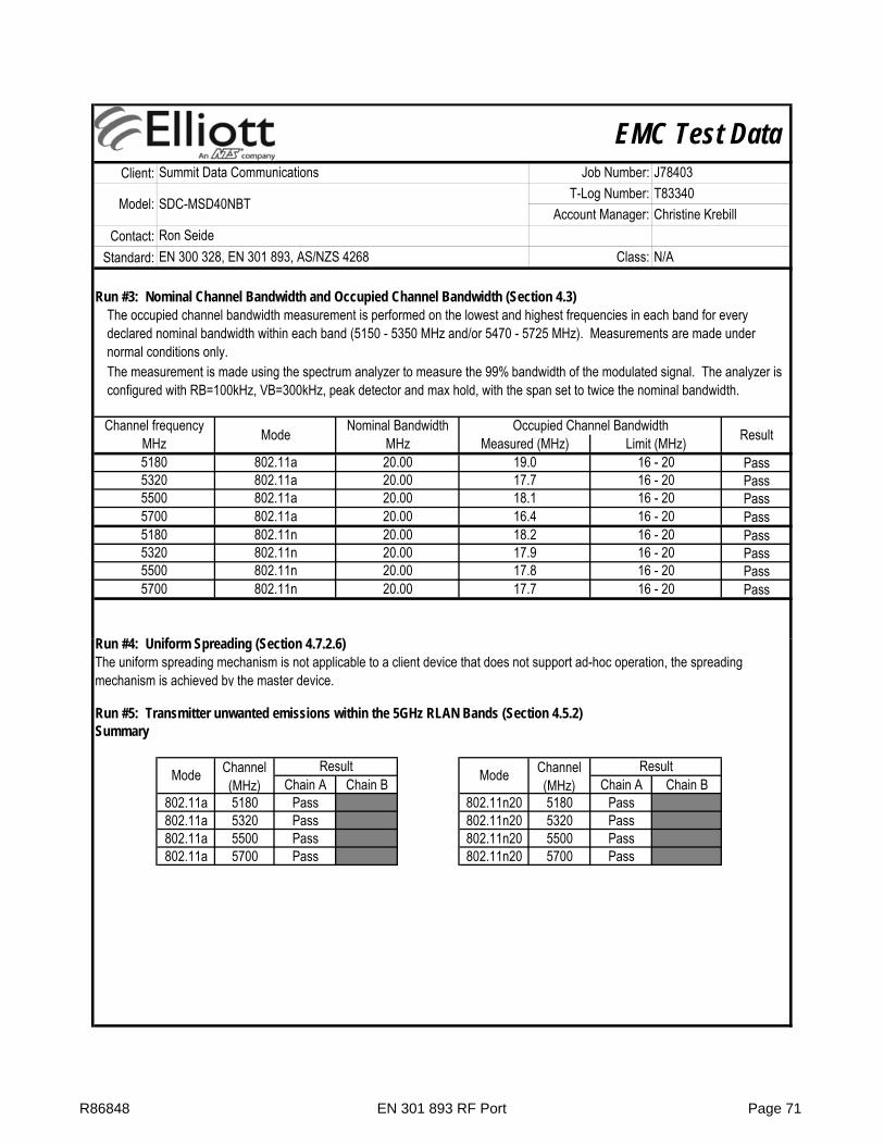
EMC Test DataClient:
Contact:Standard:
Ron SeideEN 300 328, EN 301 893, AS/NZS 4268 Class: N/A
Summit Data Communications Job Number: J78403
Model: SDC-MSD40NBTT-Log Number: T83340
Account Manager: Christine Krebill
Run #3: Nominal Channel Bandwidth and Occupied Channel Bandwidth (Section 4.3)
PassPassPassPassPassPassPassPass
R #4 U if S di (S ti 4 7 2 6)
5500 802.11n 20.00 17.8 16 - 205700 802.11n 20.00 17.7 16 - 20
5180 802.11n 20.00 18.2 16 - 205320 802.11n 20.00 17.9 16 - 20
5500 802.11a 20.00 18.1 16 - 205700 802.11a 20.00 16.4 16 - 20
5180 802.11a 20.00 19.0 16 - 205320 802.11a 20.00 17.7 16 - 20
Channel frequency Mode Nominal Bandwidth Occupied Channel Bandwidth ResultMHz MHz Measured (MHz) Limit (MHz)
The occupied channel bandwidth measurement is performed on the lowest and highest frequencies in each band for every declared nominal bandwidth within each band (5150 - 5350 MHz and/or 5470 - 5725 MHz). Measurements are made under normal conditions only.The measurement is made using the spectrum analyzer to measure the 99% bandwidth of the modulated signal. The analyzer is configured with RB=100kHz, VB=300kHz, peak detector and max hold, with the span set to twice the nominal bandwidth.
Run #4: Uniform Spreading (Section 4.7.2.6)
Run #5: Transmitter unwanted emissions within the 5GHz RLAN Bands (Section 4.5.2)Summary
Chain A Chain B Chain A Chain B802.11a 5180 Pass 802.11n20 5180 Pass802.11a 5320 Pass 802.11n20 5320 Pass802.11a 5500 Pass 802.11n20 5500 Pass802.11a 5700 Pass 802.11n20 5700 Pass
The uniform spreading mechanism is not applicable to a client device that does not support ad-hoc operation, the spreading mechanism is achieved by the master device.
Mode Channel (MHz)
Result Mode Channel (MHz)
Result
R86848 EN 301 893 RF Port Page 71

EMC Test DataClient:
Contact:Standard:
Ron SeideEN 300 328, EN 301 893, AS/NZS 4268 Class: N/A
Summit Data Communications Job Number: J78403
Model: SDC-MSD40NBTT-Log Number: T83340
Account Manager: Christine Krebill
802.11a
R86848 EN 301 893 RF Port Page 72

EMC Test DataClient:
Contact:Standard:
Ron SeideEN 300 328, EN 301 893, AS/NZS 4268 Class: N/A
Summit Data Communications Job Number: J78403
Model: SDC-MSD40NBTT-Log Number: T83340
Account Manager: Christine Krebill
R86848 EN 301 893 RF Port Page 73
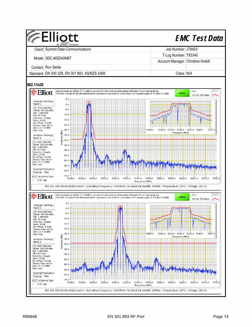
EMC Test DataClient:
Contact:Standard:
Ron SeideEN 300 328, EN 301 893, AS/NZS 4268 Class: N/A
Summit Data Communications Job Number: J78403
Model: SDC-MSD40NBTT-Log Number: T83340
Account Manager: Christine Krebill
802.11n20
R86848 EN 301 893 RF Port Page 74

EMC Test DataClient:
Contact:Standard:
Ron SeideEN 300 328, EN 301 893, AS/NZS 4268 Class: N/A
Summit Data Communications Job Number: J78403
Model: SDC-MSD40NBTT-Log Number: T83340
Account Manager: Christine Krebill
R86848 EN 301 893 RF Port Page 75

EMC Test DataClient:
Contact:Standard:
Ron SeideEN 300 328, EN 301 893, AS/NZS 4268 Class: N/A
Summit Data Communications Job Number: J78403
Model: SDC-MSD40NBTT-Log Number: T83340
Account Manager: Christine Krebill
Run #6: Transmitter unwanted emissions outside the 5 GHz RLAN bands (section 4.5.1)Transmit Mode, 30 - 26,500 MHz
R86848 EN 301 893 RF Port Page 76

EMC Test DataClient:
Contact:Standard:
Ron SeideEN 300 328, EN 301 893, AS/NZS 4268 Class: N/A
Summit Data Communications Job Number: J78403
Model: SDC-MSD40NBTT-Log Number: T83340
Account Manager: Christine Krebill
R86848 EN 301 893 RF Port Page 77

EMC Test DataClient:
Contact:Standard:
Ron SeideEN 300 328, EN 301 893, AS/NZS 4268 Class: N/A
Summit Data Communications Job Number: J78403
Model: SDC-MSD40NBTT-Log Number: T83340
Account Manager: Christine Krebill
R86848 EN 301 893 RF Port Page 78

EMC Test DataClient:
Contact:Standard:
Ron SeideEN 300 328, EN 301 893, AS/NZS 4268 Class: N/A
Summit Data Communications Job Number: J78403
Model: SDC-MSD40NBTT-Log Number: T83340
Account Manager: Christine Krebill
R86848 EN 301 893 RF Port Page 79

EMC Test DataClient:
Contact:Standard:
Ron SeideEN 300 328, EN 301 893, AS/NZS 4268 Class: N/A
Summit Data Communications Job Number: J78403
Model: SDC-MSD40NBTT-Log Number: T83340
Account Manager: Christine Krebill
Frequency Level Port Detector Channel Mode CommentsMHz dBm Limit Margin
11395.13 -31.8 RF Port -30.0 -1.8 Peak 140 n2011005.67 -33.1 RF Port -30.0 -3.1 Peak 100 n205018.34 -36.0 RF Port -30.0 -6.0 Peak 36 n20
10357.45 -39.8 RF Port -30.0 -9.8 Peak 36 n205483.49 -28.2 RF Port 10.0 -38.2 Peak 64 n20
10642.88 -36.0 RF Port -30.0 -6.0 Peak 64 n205018.34 -33.1 RF Port -30.0 -3.1 Peak 36 a
10360.12 -38.3 RF Port -30.0 -8.3 Peak 36 a5486.50 -29.6 RF Port 10.0 -39.6 Peak 64 a
10640.21 -35.4 RF Port -30.0 -5.4 Peak 64 a11003.00 -32.1 RF Port -30.0 -2.1 Peak 100 a11397.80 -46.0 RF Port -30.0 -16.0 Peak 140 a
EN 301 893
R86848 EN 301 893 RF Port Page 80
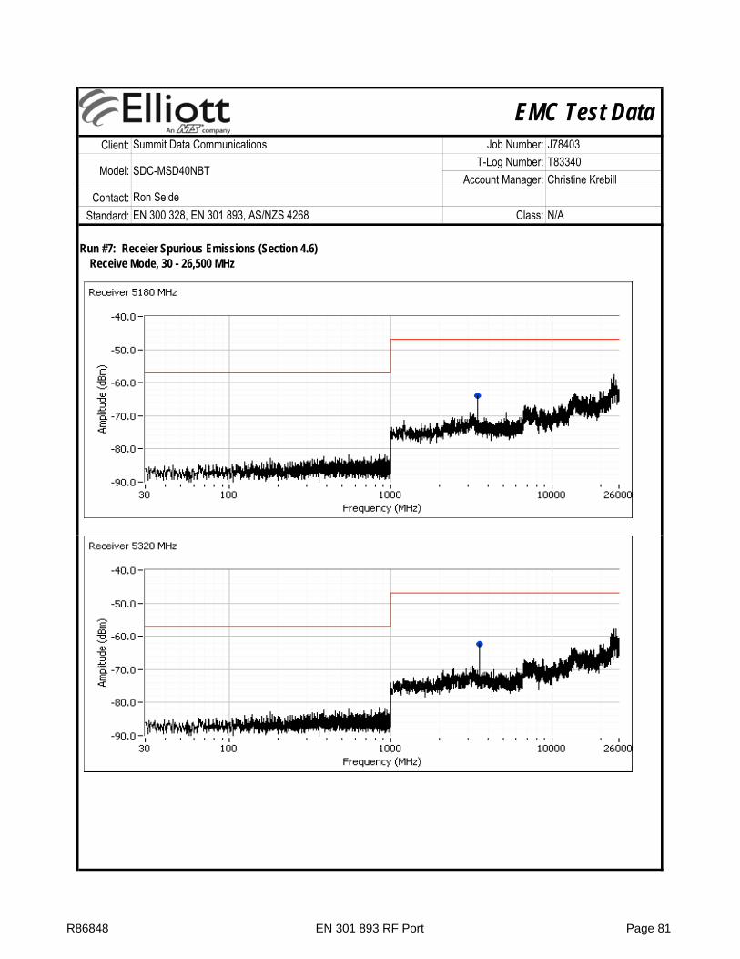
EMC Test DataClient:
Contact:Standard:
Ron SeideEN 300 328, EN 301 893, AS/NZS 4268 Class: N/A
Summit Data Communications Job Number: J78403
Model: SDC-MSD40NBTT-Log Number: T83340
Account Manager: Christine Krebill
Run #7: Receier Spurious Emissions (Section 4.6)Receive Mode, 30 - 26,500 MHz
R86848 EN 301 893 RF Port Page 81

EMC Test DataClient:
Contact:Standard:
Ron SeideEN 300 328, EN 301 893, AS/NZS 4268 Class: N/A
Summit Data Communications Job Number: J78403
Model: SDC-MSD40NBTT-Log Number: T83340
Account Manager: Christine Krebill
Frequency Level Port Detector Channel Mode CommentsMHz dBm Limit Margin
3454.820 -64.0 RF Port -47.0 -17.0 Peak 363547.850 -62.4 RF Port -47.0 -15.4 Peak 643667.890 -60.7 RF Port -47.0 -13.7 Peak 1003799.930 -60.1 RF Port -47.0 -13.1 Peak 140
EN 301 893
R86848 EN 301 893 RF Port Page 82

Elliott Laboratories -- EMC Department Test Report Report Date: March 20, 2012
File: R86848 Page 83
End of Report
This page is intentionally blank and marks the last page of this test report.