Radio Ocean requires the radio operator to meet the ... · RO4700 MARINE RADIO FU366-EUR 25/1 Watt...
22
RO4700 MARINE RADIO FU366-EUR 25/1 Watt VHF/FM OPERATOR WARNING Radio Ocean requires the radio operator to meet the requirements for Radio Frequency Exposure. Unauthorized changes or modifications to this equipment may void compliance with ETSI rule, Any change or modification must be approved in writing by Radio Ocean Corp This equipment has been tested and licensed to comply with the limits for Class D Digital Marine Devices. These limits are designed to provide reasonable protection against harmful interference in a residential installation. This equipment can generate or radiate radio frequency energy and, if not installed and used in accordance with the instructions, may cause harmful interference to radio communications and human body. Never transmit before you make sure the antenna is properly located. This device is only an aid to navigation. Its performance can be affected by many factors including equipment failure or defects, environmental condition and improper handling or use. It is the user's responsibility to exercise common prudence and navigational judgement, and this device should not be relied upon as a substitute for such prudence and judgement. Your Radio Ocean VHF radio generates and radiates radio frequency (RF) electromagnetic energy (EME), this equipment must be installed and operated in accordance with the instructions contained in this handbook. Failure to do so can result in personal injury and/or product malfunction. www.Busse-Yachtshop.de email: [email protected]
Transcript of Radio Ocean requires the radio operator to meet the ... · RO4700 MARINE RADIO FU366-EUR 25/1 Watt...
RO4700 MARINE RADIO
FU366-EUR 25/1 Watt VHF/FM
OPERATOR WARNING Radio Ocean requires the radio operator to meet the requirements for Radio Frequency Exposure. Unauthorized changes or modifications to this equipment may void compliance with ETSI rule, Any change or modification must be approved in writing by Radio Ocean Corp This equipment has been tested and licensed to comply with the limits for Class D Digital Marine Devices. These limits are designed to provide reasonable protection against harmful interference in a residential installation. This equipment can generate or radiate radio frequency energy and, if not installed and used in accordance with the instructions, may cause harmful interference to radio communications and human body. Never transmit before you make sure the antenna is properly located. This device is only an aid to navigation. Its performance can be affected by many factors including equipment failure or defects, environmental condition and improper handling or use. It is the user's responsibility to exercise common prudence and navigational judgement, and this device should not be relied upon as a substitute for such prudence and judgement. Your Radio Ocean VHF radio generates and radiates radio frequency (RF) electromagnetic energy (EME), this equipment must be installed and operated in accordance with the instructions contained in this handbook. Failure to do so can result in personal injury and/or product malfunction.
ww
w.B
usse-Yachtshop.de em
ail: [email protected]

Page 3 Page 4
TABLE OF CONTENTS 1 EQUIPMENT DESCRIPTION………………………….……………………5 1.1 INTRODUCTION…………………………………………………………….5 2. CONTROLS AND LCD DISPLAY…………………………………………6 2.1 BASE STATION PANEL……….……………….…………………….……6 2. 2 BASE STATION PANEL (REAR)…………..……………………..………8 2. 3 HANDSET………………….……………………………………………...…9 2. 4 LIQUID CRYSTAL DISPLAY……..………………………………..….…11 3. INSTALLATION…………………….…………………………….….…….12 3.1 SUPPLIED ACCESSORIES………………………………………….……12 3.2 LOCATION…………………………………………………………….……13 3.3 CONNECTIONS………………….………….……………………..………13 3.4 MOUNTING THE RADIO………..……..………………………………….15 3.5 ANTENNA MOUNTING/THE EMC EXPOSURE…………………..……16 3.6 MOUNTING THE HANDSET……………………………………………..16 3.7 RECESSED INSTALLATION……………………………………………..17 4 BASE OPERATION………………………….………………………….…18 4.1 TRANSMISSION AND RECEPTION…….………………..…………….18 4.2 CHANNEL SELECTION…………….…………………………………….18 4.3 MEMORY CHANNELS……….………………………….………….…19 4.4 TRANSMIT TIME-OUT-TIME……………………………………………..19 4.5 SCAN………………………………………………………..………………19 4.6 WATCH ………………………………………………………..……………20 4.7 POSITION INDICATON……………………………………………..20 5.0 DIGITAL SELECTIVE CALLING………………..………………….……21 5.1 GENERAL………………………………………………….….……..21 5.1.1 MARITIME MOBILE SERVICE IDENTITY(MMIS)….…………………21 5.1.2 HOW CAN I OBTAIN MMSI ASSIGNMENT?………………………..21 5.2. DSC CALL TYPE ………………………………………………………….21 5.2.1 SEND A DISTRESS CALL……………………………...……………..…23 5.2.2 SEND AN ALL SHIPS CALL…….………………………………….……23 5.2.3 SEND A GROUP CALL……………….………………………………..…24 5.2.4 MAKE A ROUTING CALL (INDIVIDUAL)………………………….…...24 5.2.4.1 MANUALLY SENDING AN INDIVIDUAL CALL……………...………..24 5.2.4.2 SENDING AN INDIVIDUAL CALL………………………………….…..25 5.2.4.3 ACK OF AN INDIVIDUAL INCOMING………………………....……….26 5.2.5 LAST CALL………………………………………………………………...26 5.2.6 SENDING AN INDIVIDUAL CALL USING THE CALL LOG……...….26 5.2.7 POS REQUEST AND POS REPLY……………………………………..26 5.2.7.1 POS REQUEST…………………………………………………………….26 5.2.7.2. POS REPLY………………………………………………………………...26 5.3 RECEIVER DSC CALL…………………………………………….………27 5.3.1 RECEIVER A DISTRESS CALL………………………………………...27 5.3.2 RECEIVING A DISTRESS ACK FROM A COAST STATION………..28 5.3.3 RECEIVER DISTRESS RELAY CALL...…………………………………28
5.3.4 RECEIVING AN ALL SHIPS CALL……………………………………….28 5.3.5 RECEIVING A GROUP CALL.……………………………………...29 5.3.6 RECEIVING AN INDIVIDUAL CALL …………………………………..29 5.3.7 RECEIVING AN “POSITION REPLY” CALL……………..……………29 5.3.8 RECEIVING A GEOGRAPHIC AREA CALL…………………………….30 6.0 SET-UP MENUS…………………………….…………………………..…30 6.1 MENU FUNCTION DESCRIPTION………….…………………….…….30 6.2 SET-UP MENU NAVIGATION…..……………………………………….30 6.3 BUDDY LIST…………………………………………………………31 6.3.1 ADDING AN ENTRY………………………………………………………31 6.3.2 EDIT EXISTING ENTRY …………………………………….……………31 6.3.3 DELETE AN ENTRY……………………………………………………... 32 6.4 BACK-LIGHT ADJUSTMENT……………………………………………32 6.5 CONTRAST ADJUSTMENT……………………………………………..32 6.6 GPS/TIME …………………………………………………………….…….32 6.6.1 MANUAL ENTRY GPS DATA…………………………………………….33 6.6.2 SETTING…………………………………………………………….………33 6.6.2.1 POSITION DISPLAY ON/OFF…………………………………………….33 6.6.2.2 TIME DISPLAY ON/OFF..…………………………………………………34 6.6.2.3 LOCAL TIME (TIME OFFSET)...…………………………………………34 6.6.2.4 TIME FORMAT OPTIONS (TIME FORMAT)…………………………….34 6.6.2.5 COURSE/SPEED DISPLAY OPTIONS (COG/SOG)…………………35 6.7 RADIO SETUP ……………………………………………………………..35 6.7.1.1 CHANNEL NAME DISPLAY………………………………………………35 6.7.1.2 CHANNEL NAME EDITING……………………………………………….35 6.7.2 RING VOLUME ADJUSTMENT……………………………...…………36 6.7.3 BEEP VOLUME ADJUSTMENT………………………………………….36 6.7.4 INTERNAL SPEAKER ON/OFF…………………………………………..36 6.8 DSC SETUP………………………………………………...……………….37 6.8.1 ENTER YOUR USER MMSI……………………………...…………..37 6.8.2 MAINTAIN GROUPS……………………………………………………….38 6.8.2.1 ENTER YOUR GROUPS…………………………………...……………38 6.8.2.2 EDIT USER GROUPS………………………………………………………38 6.8.2.3 DELETE A GROUP…………………………………………………………38 6.8.3 INDIV REPLY………………………………………………………………39 6.8.4 DSC ENABLE……………………………………………………………….39 6.8.5 POS REPLY………………………………………………….…….……..…40 6.9 RESET……………………………………………………..…………………40 7 MAINTENANCE…………………………………………………….………41 8 SPECIFICATION……………………………………………………………42 9 FREQUENCY TABLE……………………………………………………..43
ww
w.B
usse-Yachtshop.de em
ail: [email protected]

Page 5 Page 6
1 Equipment Description 1.1 INTRODUCTION
Congratulations on your purchase of Radio Ocean’s RO 4700 marine band radio. Base Station Radio with output power of 25/1 watt. It should be powered by a 13.8VDC power supply. The radio can support DSC (Digital Selective Calling) operation with specially designed DSC unit, which meets the standard of ITU-R, M493-10. When being connected with GPS, it will display the position (longitude and latitude) of the vessel. Compact fist microphone with digital keys makes for convenient operation of the equipment
Other features of the radio includes: Access to all available INTL channels (currently allocated). Allows memory all INTL channels for quick recall and memory scan. Provides as many as 20 user programmable names with MMSI, 10 distress
calls and 20 individual calls for DSC communications. Rotary volume control with power on/off, rotary channel selector and rotary
squelch adjustable knob give you more convenient operation of the radio. Outstanding performance of waterproof complying with Japanese Industry
Standard level 7. 25 watts high output power allows you make contact with others in a long
distance of marine communication and 1watt low power for short distance. Separate 16button for quick selection of the emergency call on CH16. Adjustable brightness of backlit for good visibility of large LCD various
circumstance. External interface easy to connect to GPS and external speaker. Mounting gimbal for firm and reliable location of your base station in
difference condition. 1.2 ETSI INFORMATION ETSI (European Telecommunications Standard Institute) has stipulated the specific requirements (EN 301 025-1/2/3) on marine radio with class D DSC feature, for use on non-SOLAS vessels.
2 CONTROLS AND LCD DISPLAY 2.1 BASE STATION (PANEL)
(1) Volume and Power On/Off 0-270°rotary control knob, turn clockwise to power on.
Continue to turn until a comfortable audio level. (2) Squelch Use this knob to set the squelch threshold,
(3) CH/enter Rotary encoder (no stop) with momentary push
` Rotate this knob to change the current number and change values in menu mode or during programming. Press the knob to enter values
(4) Band / Save Select band and set memory channels (5) Cancel the key to cancel last selection or change without
saving. It allows step back one level on menu mode. It cancels DSC Distress calls & auto-retransmission of DISTRESS calls.
(1)
(2)
(3)
(4)
(5) (6)
(7) (8)
(9)
(10)
(11)
(12)
(13)
ww
w.B
usse-Yachtshop.de em
ail: [email protected]
Page 7 Page 8
(6) DSC /menu Use this key to enter Menu Setup or DSC Call Menu Call Mode is used for making DSC Calls. Menu Mode is
used to setup the radio. (7) Hi/Low/mem Press and release HI/LO button to toggle between
power output 25watt and output 1 watt. “HI” or “LO” icon appears on LCD display to indicate setting Hold the key select memory channel mode
(8) Scan Start and stop normal or priority scan and MEM channels and priority channels scan.
(9) Watch Start dual watch or tri-watch, Stop dual watch or tri-
watch. (10) 16 Press 16 key to quit all other modes and to into the
priority channel. (11) DISTRESS this button is used to send a signal of distress in case of
emergency. See DSC Operation for details of sending the call. This button is cover by a spring cover.
The Distress Function or any other transmitted DSC function does not work unless a user’s MMSI has been entered. .
(12) LCD: Large LCD (2“×1.5”) with viewable area of 4×12 dot matrix makes it easy to be read.
(13) Built-in Speaker Guarantee a clear ring and voice communication
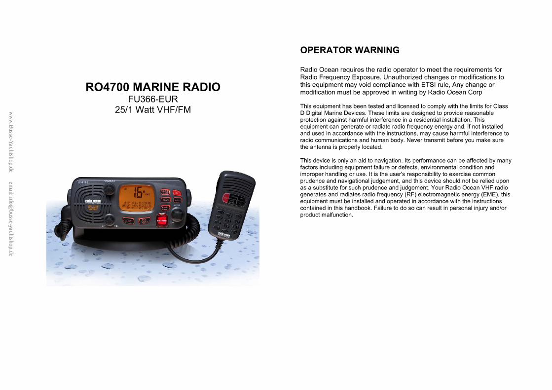
2.2 BASE STATION (REAR)
① Antenna Jack: Connect a suitable antenna to your marine VHF radio to get a satisfying communication.
② Power Source Connect the radio to a 13.8 VDC power source. ③ External Speaker Connection Cable
If need be, you can also use this cable to connect an external speaker.
④ GPS Connector Connect the radio to a GPS receiver to acquire the position and time information of your vessel
ww
w.B
usse-Yachtshop.de em
ail: [email protected]

Page 9 Page 10
2.3 HANDSET ① Channel Up/ Down Press and release to change channel. ② 16 Press 16 key to quit all other modes and to into
the priority channel. ③ Hi/Low: Press and release HI/LO button to toggle
between power output 25 watt and output.1 watt ④ PTT: Push to hold to transmit; release to receiver. . ⑤ DSC/MENU Use this button to enter Menu setup or DSC call
Menu Call Mode is used for making DSC Calls. Menu Mode is used to setup the radio
⑥ Alphanumeric Alphanumeric symbol keys total 12 units, it is
used to input alphabet and numbers also left shift, right shift ,cancel enter. Under normal operation, the numerical key ( 0 – 9 ) enable direct channel access function. Whenever 1st digit key in, the display will flash the digit # but not yet tune the channel. If no more key in within keystroke time out , the channel will be tuned immediately. If another digit key pressed
within the time-out period, the key in 2-digit channel # will be recalled immediately.
Under the Menu mode, those keys can be used to entry the MMIS# and set the required Numerical data. Besides the numerical data could be key in, those keys could be used to enter the channel name and edit the Buddy list
Key 0 1 2 3 4 5 6 7 8 9 Normal mode & Menu Mode
0 1 2 3 4 5 6 7 8 9
Edit Mode 1st stroke
( - A D G J M P T W
2nd stroke ) . B E H K N Q U X 3rd stroke % , C F I L O R V Y 4th stroke / ? ! : # ‘ S & Z 5th stroke 0 1 2 3 4 5 6 7 8 9 Press CH UP/DOWN to move the cursor Up/Down Press </>to move the cursor Left/Right The highlighted digit will be blinked and allow user to over-write the new digit or character. After edit finish, press ENT key to confirm the changes and quit the menu. (note: short press</>keys means to move the cursor Left/Right, long press </>keys show cancel /confirmation =
① ②
④ ③
⑤ ⑥
ww
w.B
usse-Yachtshop.de em
ail: [email protected]
Page 11 Page 12
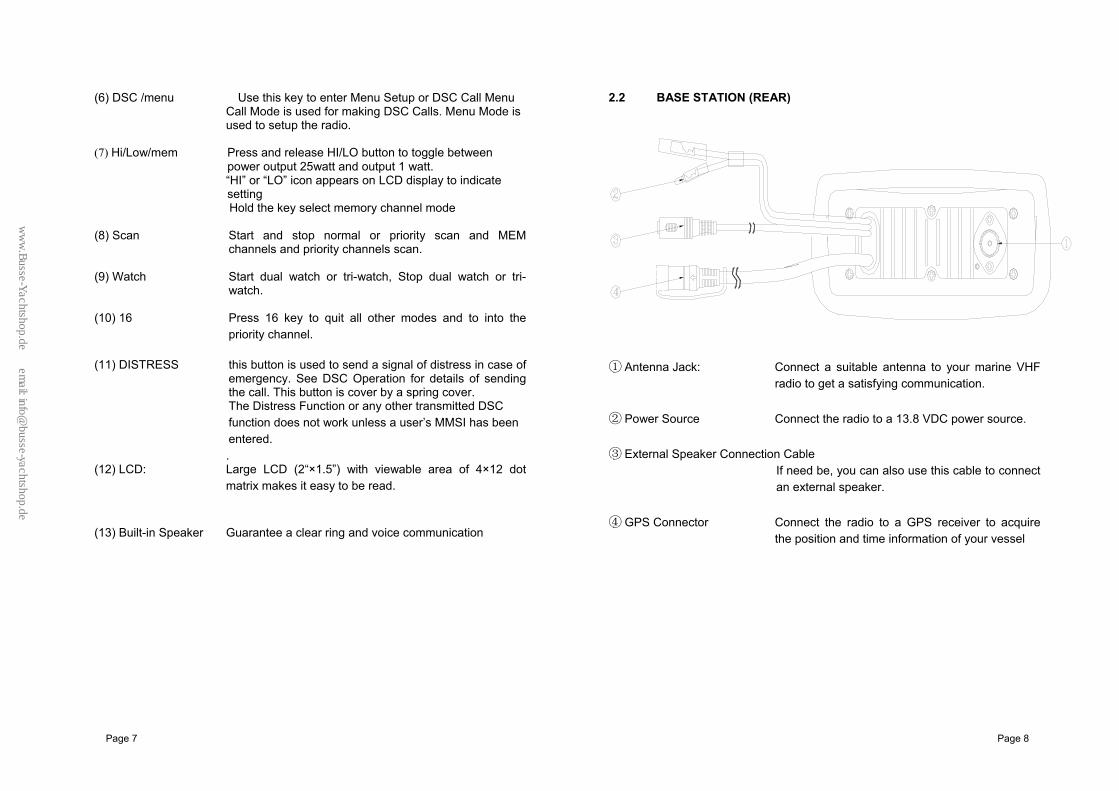
2.4 LCD SYMBOL AND MEANINGS
SYMBOL MEANINGS HI LO Transmission power high (HI) 25W or low (Lo) 1W.
Indicates an incoming DSC call or blank to notify you of any unread call log messages.
TX Indicate that the radio is Transmitting RX Indicate that the radio is receiving a radio signal. M Indicate the current channel has been saved in memory.
Indicate the current work at Memory mode (Channel is selected at saved channels).
DU TRI Indicate Watch state. ALT A weather alert signal are received, In US and Canada 88 Channel selected. I Indicates channel bank for VHF radio operations and regulations. PSCAN Indicate the current work in priority-scan mode. SCAN Indicate the current work at the scan mode. DSC DSC capability is available.
Battery Low indicates vessel battery voltage is low.
X Channel is temporarily deleted from the all scan operation. ATIS Enable for use In European in inland waterway other wise blank Dot Matrix Display indicates special conditions or radio functions.
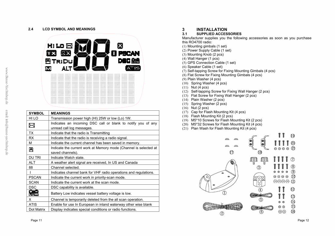
3 INSTALLATION 3.1 SUPPLIED ACCESSORIES Manufacturer supplies you the following accessories as soon as you purchase this RO4700 radio: (1) Mounting gimbals (1 set) (2) Power Supply Cable (1 set) (3) Mounting Knob (2 pcs) (4) Wall Hanger (1 pcs) (5) GPS Connection Cable (1 set) (6) Speaker Cable (1 set) (7) Self-tapping Screw for Fixing Mounting Gimbals (4 pcs) (8) Flat Screw for Fixing Mounting Gimbals (4 pcs) (9) Plain Washer (4 pcs) (10) Spring Washer (4 pcs) (11) Nut (4 pcs) (12) Self-tapping Screw for Fixing Wall Hanger (2 pcs) (13) Flat Screw for Fixing Wall Hanger (2 pcs) (14) Plain Washer (2 pcs) (15) Spring Washer (2 pcs) (16) Nut (2 pcs) (17) Cap for Flash Mounting Kit (4 pcs) (18) Flash Mounting Kit (2 pcs) (19) M5*10 Screws for Flash Mounting Kit (2 pcs) (20) M5*32 Screws for Flash Mounting Kit (4 pcs) (21) Plan Wash for Flash Mounting Kit (4 pcs)
ww
w.B
usse-Yachtshop.de em
ail: [email protected]

Page 13 Page 14
3.2 LOCATION REQUIREMENTS
To more conveniently and efficiently use your marine radio, find a mounting location that:
Is far enough from any devices like devices to avoid any interference caused by the speaker magnet in your radio during their operation;
Provides accessibility to the front panel controls; Allows connection to a power supply and an antenna; Has free space nearby for installation of a handset hanger; Where the antenna can be mounted at least 3 feet from radio.
3.3 CONNECTIONS POWER SUPPLY You radio should be powered by a 13.8VDC power supply. Red cable is for positive pole and the thicker black one is for negative pole. EXTERNAL SPEAKER If needed, you can connect your radio to an external speaker with the supplied connection cable. White cable is for positive pole and the thinner black one is for negative pole. GPS EQUIPMENT When your marine radio RO4700 is connected by the GPS cable to a GPS equipment, it can obtain the information of both its current location (longitude and latitude) and the local GMT. GPS CABLE Line up the arrow on the connector with the arrow on the GPS cable (supplied)
and then plug together. The GPS cable has eight pins as follows: Pin Wire Function 1 Red Not used. 2 Orange NMEA OUT (+) 3 White Not used 4 Green NMEA IN (-) from GPS navigation receiver 5 Yellow NMEA IN (+) from GPS navigation receiver 6 Black NMEA OUT (-) 7 Blue Not used 8 Grey Not used
NEMA 0183 Version (1.5 to 3.0) sentence format:: GLL, GGA, RMC, GNS. Note: never short wires, this may cause damage.
Connecting: GPS cable round plug to radio and the wire of yellow and the green connect to GPS navigation receiver.
ANTENNA A very important part for the performance of any communication system is a suitable antenna. Consult your dealer about antennas and ask them to help to mount your radio.
To RO4700 GPS connector
ORA NGE
GRE E N
Y E L L OW
B L A C K
ww
w.B
usse-Yachtshop.de em
ail: [email protected]
Page 15 Page 16
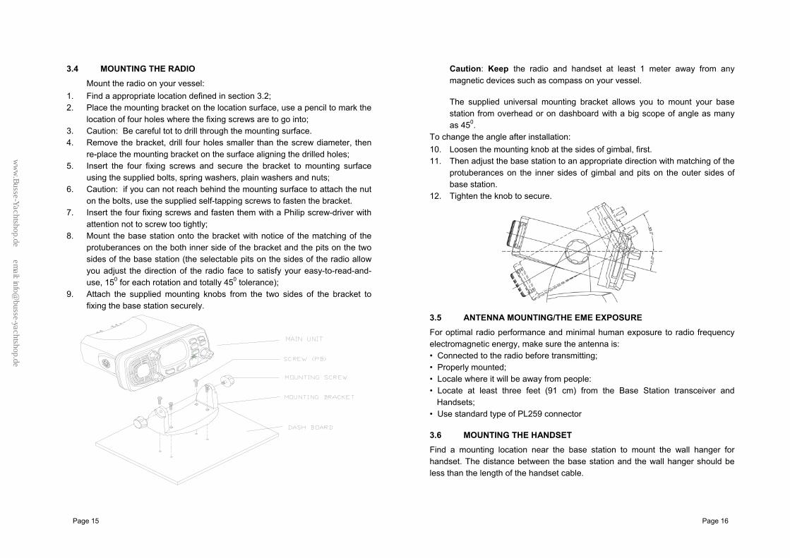
3.4 MOUNTING THE RADIO
Mount the radio on your vessel: 1. Find a appropriate location defined in section 3.2; 2. Place the mounting bracket on the location surface, use a pencil to mark the
location of four holes where the fixing screws are to go into; 3. Caution: Be careful tot to drill through the mounting surface. 4. Remove the bracket, drill four holes smaller than the screw diameter, then
re-place the mounting bracket on the surface aligning the drilled holes; 5. Insert the four fixing screws and secure the bracket to mounting surface
using the supplied bolts, spring washers, plain washers and nuts; 6. Caution: if you can not reach behind the mounting surface to attach the nut
on the bolts, use the supplied self-tapping screws to fasten the bracket. 7. Insert the four fixing screws and fasten them with a Philip screw-driver with
attention not to screw too tightly; 8. Mount the base station onto the bracket with notice of the matching of the
protuberances on the both inner side of the bracket and the pits on the two sides of the base station (the selectable pits on the sides of the radio allow you adjust the direction of the radio face to satisfy your easy-to-read-and-use, 150 for each rotation and totally 450 tolerance);
9. Attach the supplied mounting knobs from the two sides of the bracket to fixing the base station securely.
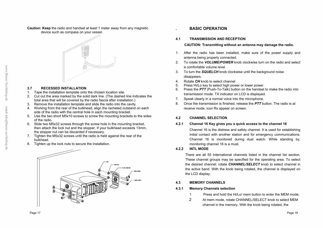
Caution: Keep the radio and handset at least 1 meter away from any magnetic devices such as compass on your vessel.
The supplied universal mounting bracket allows you to mount your base station from overhead or on dashboard with a big scope of angle as many as 450.
To change the angle after installation: 10. Loosen the mounting knob at the sides of gimbal, first. 11. Then adjust the base station to an appropriate direction with matching of the
protuberances on the inner sides of gimbal and pits on the outer sides of base station.
12. Tighten the knob to secure.
3.5 ANTENNA MOUNTING/THE EME EXPOSURE
For optimal radio performance and minimal human exposure to radio frequency electromagnetic energy, make sure the antenna is: • Connected to the radio before transmitting; • Properly mounted; • Locale where it will be away from people: • Locate at least three feet (91 cm) from the Base Station transceiver and
Handsets; • Use standard type of PL259 connector 3.6 MOUNTING THE HANDSET Find a mounting location near the base station to mount the wall hanger for handset. The distance between the base station and the wall hanger should be less than the length of the handset cable.
ww
w.B
usse-Yachtshop.de em
ail: [email protected]
Page 17 Page 18
Caution: Keep the radio and handset at least 1 meter away from any magnetic device such as compass on your vessel.
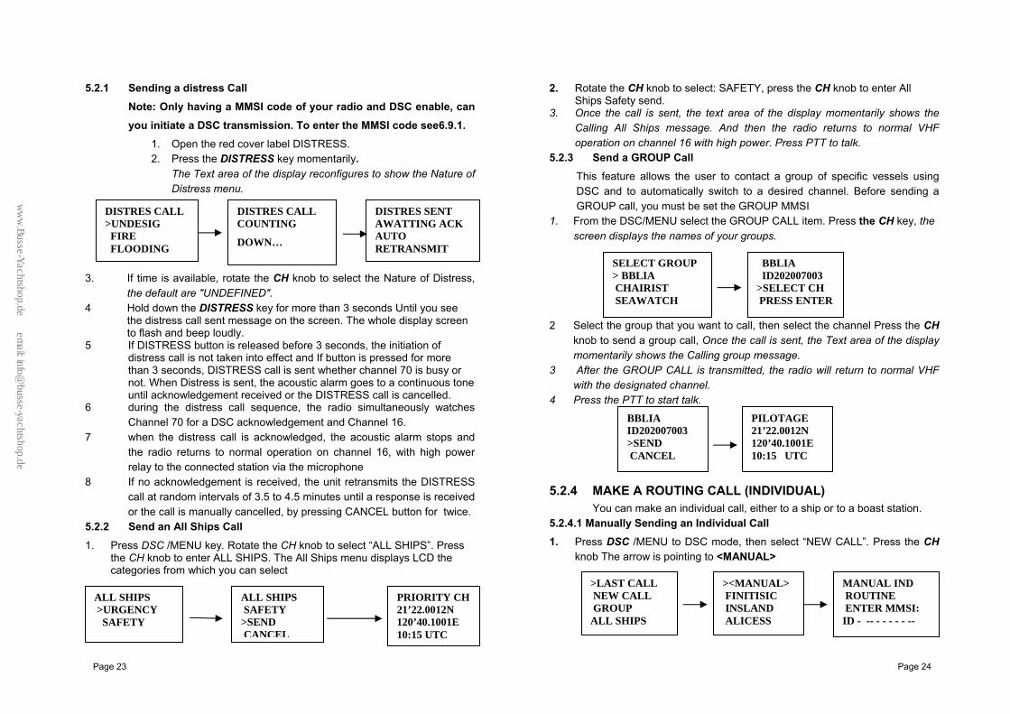
3.7 RECESSED INSTALLATION 1. Tape the installation template onto the chosen location site. 2. Cut out the area marked by the solid dark line. (The dashed line indicates the
total area that will be covered by the radio fascia after installation.) 3. Remove the installation template and slide the radio into the cavity. 4. Working from the rear of the bulkhead, align the racheted outstand on each
side of the radio with the central hole in each mounting bracket. 5. Use the two short M5x10 screws to screw the mounting brackets to the sides
of the radio. 6. Slide two M5x32 screws through the screw hole in the mounting bracket,
then attach the lock nut and the stopper. If your bulkhead exceeds 13mm, the stopper nut can be discarded if necessary.
7. Tighten the M5x32 screws until the radio is held against the rear of the bulkhead.
8. Tighten up the lock nuts to secure the installation.
. BASIC OPERATION 4.1 TRANSMISSION AND RECEPTION
CAUTION: Transmitting without an antenna may damage the radio.
1. After the radio has been installed, make sure of the power supply and antenna being properly connected.
2. To rotate the VOLUME/POWER knob clockwise turn on the radio and select a comfortable volume level.
3. To turn the SQUELCH knob clockwise until the background noise disappears.
4. Rotate CH knob to select channel 5. Press Hi/Lo key to select high power or lower power. 6. Press the PTT (Push-To-Talk) button on the handset to make the radio into
transmission mode. TX indicator on LCD is displayed. 7. Speak clearly in a normal voice into the microphone. 8. Once the transmission is finished, release the PTT button. The radio is at
receive mode, icon Rx appear on screen. 4.2 CHANNEL SELECTION 4.2.1 Channel 16 Key gives you a quick access to the channel 16
Channel 16 is the distress and safety channel. It is used for establishing initial contact with another station and for emergency communications. Channel 16 is monitored during dual watch. While standing by, monitoring channel 16 is a must.
4.2.2 INTL MODE There are all 55 International channels listed in the channel list section. These channel groups may be specified for the operating area. To select the desired channel: rotate CHANNEL/SELECT knob to select channel in the active band. With the knob being rotated, the channel is displayed on the LCD display;
4.3 MEMORY CHANNELS 4.3.1 Memory Channels selection
1 Press and hold the Hi/Lo/ mem button to enter the MEM mode; 2 At mem mode, rotate CHANNEL/SELECT knob to select MEM
channel in the memory. With the knob being rotated, the
ww
w.B
usse-Yachtshop.de em
ail: [email protected]

Page 19 Page 20
channel and the icon M will be turned on for indication that channel be saved in MEM lists displayed on the LCD display
4.3.2 SAVE favorite the Channels Your can store in the hope of channels as favorite channel. Program the FAV channel and store Process as follow:
1. At normal mode, tune to the desired channel and then press and hold
the BAND/SAVE key to save it as Favorite channel. The icon will be turned on for indication that channel be saved in FAV list.
2. Then tune to next desired channel and repeat the keystroke sequences till all desired channels be programmed / saved.
4.3.3 MEM Channels delete 1 Delete the channel from the MEM list at Normal mode. Select
the target channel with icon ON. Press and hold the BAND/SAVE key till the icon turn OFF. The target channel will then be deleted out from the MEM list. Repeat the keystroke operation for those unwanted channels.
2 If no channel has been programmed, an error beep occurs with indicate error message.
4.4 Transmit time-out timer (TOT)
When the PTT button on the microphone is held down, transmit time is limited to 5 minutes. This will avoid unintentional transmissions. About 10 second before automatic transmitter shutdown, a warning beep will be heard from the speaker(s). The transceiver will automatically go to receive mode. Before transmitting again, the PTT button must be released and then pressed again.
4.5 Scan:
Scanning is an efficient way to locate signals quickly over a wide frequency range.
The transceiver Scan mode has 2 types available: normal scan, memory channels scan. If no memory channels the way is normal all scan (1.2.3.4…), if there are memory channels only scan memory channels, every one’s have a normal scan and the priority scan
1 During normal scan Press and hold SCAN Key over 3sec, the Priority scan mode (1,16,2,16,3,16…) will be selected. P-scan icon will be appear on LCD Press and hold SCAN key over
3sec to turn it back to normal scan, the scan mode icon will be display.
2 During the SCAN modes: Press Up/Down key (CH knob clockwise/anti-clockwise) will change the scan direction.
3 Press SCAN key again will terminate the scan operation and stop at the last used channel. Press CANCEL key will also terminate the scan function and state at the last used channel
It also can be to cancel by 16.PTT. 4.6 Watch 4.6.1 Dual watch
Press Watch key to activate the DUAL WATCH mode. Monitor the current channel and Ch 16 in cycle. Icon “DU” will appear on the LCD.
4.6.2 Tri-watch
Press and hold Watch key to activate the TRI WATCH mode. Monitor the current channel, CH 16 and CH 9 in cycle. Icon “TRI” will be turn ON To quit the mode, press WATCH, 16, DSC/MENU, CANCEL key, Press PTT key to TX mode of current channel
4.7 POSITION INDICATION Your transceiver can display the position of the vessel’s (longitude and latitude) as well as time and data information, if connected to a GPS receiver; if no GPS equipment to be connected,an alert tone of 1-minute duration witch can cancelled By any button is sounded at 4 hour intervals to encourage manual input of positional data . Once no manual input is made for 23.5 hours, GPS disappears from the screen, the position data transmitted goes to 9’s and all the time data goes to 8’s.
5 DIGITAL SELECTIVE CALLING 5.1 GENERAL DSC(Digital Selective Calling) is a semi-automated method of establishing a radio call, it has been designated by the International Maritime Organization (IMO) as an international standard for establishing VHF, MF and HF radio calls. It had
DISTRESS 23’20.1234 N 100’15.1002 E 08:10 UTC
ww
w.B
usse-Yachtshop.de em
ail: [email protected]

Page 21 Page 22
also been designated part of the Global Maritime Distress and Safety System (GMDSS). It is planed that DSC will eventually replace aural watches on distress frequencies and will be used to announce routine and urgent maritime safety information broadcasts. This new service will also allow mariners to initiate or receive distress, urgency, safety and routine calls to or from another vessel equipped with a DSC transceiver. 5.1.1 MARITIME MOBILE SERVICE IDENTITY
An MMIS is a nine digit number used on Marine Transceiver capable of using Digital Selective Calling (DSC). This number is used like a telephone number to selectively call other vessels. Refer to section 6.12 (USER MMSI ENTRY).
5.1.2 HOW CAN I OBTAIN A MMSI ASSIGNMENT? Contact your dealer.
WARNING
This radio is designed to generate a digital maritime distress and safety call to facilitate search and rescue. To be effective as a safety device, this equipment must be used only within communication range of a shore–based VHF marine channel70 distress and safety watch system. The range of signal may very but under normal conditions should be approximately 20 nautical miles.
5.2 DSC CALL TYPES
Press the DSC/MENU key to pop up the menu for user to select the DSC call type to send. Note that only four calls can be shown at any one time on the screen. Press + /–or rotate the CH knob scroll up and down the call types until the cursor is positioned at the desired option. Press the Ch knob the call types are: Call Type Description
LAST CALL Recall last call no matter what type of call received at last.
NEW CALL Make a new call, by inputting the MMSI or pick up from the list max 20
GROUP Sends transmissions that are only received by radios that share a common group MMSI number, up to 3 group MMSI numbers can be stored and call.
ALL SHIPS Make an Urgency or Safety call to all ships. CALL LOG Allow a review of all stored Calls by number and time
of call. An individual call type can be placed to the selected MMSI/NAME in the LOG. The call at the end of the list is automatically erased. The earliest call stored at the end of the list. There is 20 calls could be stored.
DISTRESS Log Allow a review of all stored Distress calls by number and time of call. The call at the end of the list is automatically erased. The earliest call stored at the end of the list. There is also 10 calls could be stored.
POS REQUEST The option enables you to request GPS position information from any vessel for which an MMSI number is known, such request can pick up from Buddy list or manual entry.
EXIT quit the menu mode DISTRESS A specific Distress key is used to make the
distress call. The call send out the position and time information from the input NMEA data along with your MMSI number. This digital information lets other ships and shore equipped with appropriate DSC equipment know where you are and that you are in a distress situation, except immediate help is needed, never use the distress call.
ww
w.B
usse-Yachtshop.de em
ail: [email protected]
Page 23 Page 24
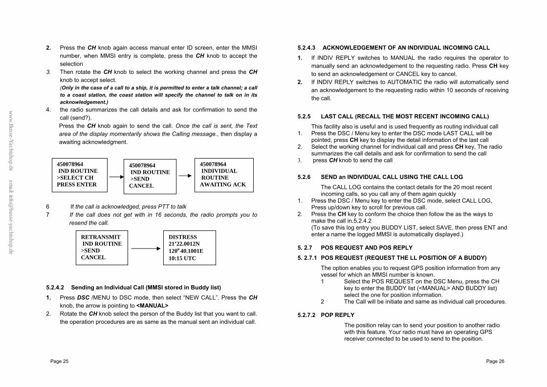
5.2.1 Sending a distress Call Note: Only having a MMSI code of your radio and DSC enable, can you initiate a DSC transmission. To enter the MMSI code see6.9.1.
1. Open the red cover label DISTRESS. 2. Press the DISTRESS key momentarily.
The Text area of the display reconfigures to show the Nature of Distress menu.
3. If time is available, rotate the CH knob to select the Nature of Distress, the default are "UNDEFINED".
4 Hold down the DISTRESS key for more than 3 seconds Until you see the distress call sent message on the screen. The whole display screen to flash and beep loudly.
5 If DISTRESS button is released before 3 seconds, the initiation of distress call is not taken into effect and If button is pressed for more than 3 seconds, DISTRESS call is sent whether channel 70 is busy or not. When Distress is sent, the acoustic alarm goes to a continuous tone until acknowledgement received or the DISTRESS call is cancelled.
6 during the distress call sequence, the radio simultaneously watches Channel 70 for a DSC acknowledgement and Channel 16.
7 when the distress call is acknowledged, the acoustic alarm stops and the radio returns to normal operation on channel 16, with high power relay to the connected station via the microphone
8 If no acknowledgement is received, the unit retransmits the DISTRESS call at random intervals of 3.5 to 4.5 minutes until a response is received or the call is manually cancelled, by pressing CANCEL button for twice.
5.2.2 Send an All Ships Call
1. Press DSC /MENU key. Rotate the CH knob to select “ALL SHIPS”. Press the CH knob to enter ALL SHIPS. The All Ships menu displays LCD the categories from which you can select
2. Rotate the CH knob to select: SAFETY, press the CH knob to enter All Ships Safety send.
3. Once the call is sent, the text area of the display momentarily shows the Calling All Ships message. And then the radio returns to normal VHF operation on channel 16 with high power. Press PTT to talk.
5.2.3 Send a GROUP Call This feature allows the user to contact a group of specific vessels using DSC and to automatically switch to a desired channel. Before sending a GROUP call, you must be set the GROUP MMSI
1. From the DSC/MENU select the GROUP CALL item. Press the CH key, the screen displays the names of your groups.
2 Select the group that you want to call, then select the channel Press the CH
knob to send a group call, Once the call is sent, the Text area of the display momentarily shows the Calling group message.
3 After the GROUP CALL is transmitted, the radio will return to normal VHF with the designated channel.
4 Press the PTT to start talk. 5.2.4 MAKE A ROUTING CALL (INDIVIDUAL)
You can make an individual call, either to a ship or to a boast station. 5.2.4.1 Manually Sending an Individual Call 1. Press DSC /MENU to DSC mode, then select “NEW CALL”. Press the CH
knob The arrow is pointing to <MANUAL>
SELECT GROUP > BBLIA CHAIRIST SEAWATCH
BBLIA ID202007003 >SELECT CH PRESS ENTER
>LAST CALL NEW CALL GROUP ALL SHIPS
><MANUAL> FINITISIC INSLAND ALICESS
MANUAL IND ROUTINE ENTER MMSI: ID - -- - - - - - --
BBLIA ID202007003 >SEND CANCEL
PILOTAGE 21’22.0012N 120’40.1001E 10:15 UTC
DISTRES CALL >UNDESIG FIRE FLOODING
DISTRES CALL COUNTING
DOWN…
DISTRES SENT AWATTING ACK AUTO RETRANSMIT
PRIORITY CH21’22.0012N 120’40.1001E 10:15 UTC
ALL SHIPS SAFETY >SEND CANCEL
ALL SHIPS >URGENCY SAFETY
ww
w.B
usse-Yachtshop.de em
ail: [email protected]
Page 25 Page 26
2. Press the CH knob again access manual enter ID screen, enter the MMSI number, when MMSI entry is complete, press the CH knob to accept the selection
3. Then rotate the CH knob to select the working channel and press the CH knob to accept select. (Only in the case of a call to a ship, it is permitted to enter a talk channel; a call to a coast station, the coast station will specify the channel to talk on in its acknowledgement.)
4. the radio summarizes the call details and ask for confirmation to send the call (send?). Press the CH knob again to send the call. Once the call is sent, the Text area of the display momentarily shows the Calling message., then display a awaiting acknowledgment.
6 If the call is acknowledged, press PTT to talk 7 If the call does not get with in 16 seconds, the radio prompts you to
resend the call. 5.2.4.2 Sending an Individual Call (MMSI stored in Buddy list) 1. Press DSC /MENU to DSC mode, then select “NEW CALL”. Press the CH
knob, the arrow is pointing to <MANUAL> 2. Rotate the CH knob select the person of the Buddy list that you want to call.
the operation procedures are as same as the manual sent an individual call.
5.2.4.3 ACKNOWLEDGEMENT OF AN INDIVIDUAL INCOMING CALL 1. If INDIV REPLY switches to MANUAL the radio requires the operator to
manually send an acknowledgement to the requesting radio. Press CH key to send an acknowledgement or CANCEL key to cancel.
2. If INDIV REPLY switches to AUTOMATIC the radio will automatically send an acknowledgement to the requesting radio within 10 seconds of receiving the call.
5.2.5 LAST CALL (RECALL THE MOST RECENT INCOMING CALL)
This facility also is useful and is used frequently as routing individual call 1. Press the DSC / Menu key to enter the DSC mode LAST CALL will be
pointed, press CH key to display the detail information of the last call 2. Select the working channel for individual call and press CH key, The radio
summarizes the call details and ask for confirmation to send the call 3. press CH knob to send the call 5.2.6 SEND an INDIVIDUAL CALL USING THE CALL LOG
The CALL LOG contains the contact details for the 20 most recent incoming calls, so you call any of them again quickly
1. Press the DSC / Menu key to enter the DSC mode, select CALL LOG, Press up/down key to scroll for previous call.
2. Press the CH key to conform the choice then follow the as the ways to make the call in.5.2.4.2 (To save this log entry you BUDDY LIST, select SAVE, then press ENT and enter a name the logged MMSI is automatically displayed.)
5. 2.7 POS REQUEST AND POS REPLY 5. 2.7.1 POS REQUEST (REQUEST THE LL POSITION OF A BUDDY)
The option enables you to request GPS position information from any vessel for which an MMSI number is known. 1 Select the POS REQUEST on the DSC Menu, press the CH
key to enter the BUDDY list (<MANUAL> AND BUDDY list) select the one for position information.
2 The Call will be initiate and same as individual call procedures.
5.2.7.2 POP REPLY
The position relay can to send your position to another radio with this feature. Your radio must have an operating GPS receiver connected to be used to send to the position.
450078964 IND ROUTINE >SEND CANCEL
450078964 IND ROUTINE >SELECT CH PRESS ENTER
450078964 INDIVIDUAL ROUTINE AWAITING ACK
RETRANSMIT IND ROUTINE >SEND CANCEL
DISTRESS 21’22.0012N 120º40.1001E 10:15 UTC
ww
w.B
usse-Yachtshop.de em
ail: [email protected]
Page 27 Page 28
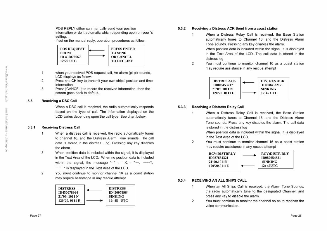
POS REPLY either can manually send your position information or do it automatic which depending upon on your ‘s setting. If set on the manual reply, operation procedures as follow:
1 when you received POS request call, An alarm (pi-pi) sounds, LCD displays as follow:
2 Press the CH key to transmit your own ships’ position and time information
3 Press [CANCEL]t to record the received information, then the screen goes back to default.
5.3. Receiving a DSC Call
When a DSC call is received, the radio automatically responds based on the type of call. The information displayed on the LCD varies depending upon the call type. See chart below.
5.3.1 Receiving Distress Call
1 When a distress call is received, the radio automatically tunes to channel 16, and the Distress Alarm Tone sounds. The call data is stored in the distress. Log. Pressing any key disables the alarm.
3 When position data is included within the signal, it is displayed in the Text Area of the LCD. When no position data is included within the signal, the message "--º--, ---X, ---º--, ----Y, --:--" is displayed in the Text Area of the LCD.
2 You must continue to monitor channel 16 as a coast station may require assistance in any rescue attempt
5.3.2 Receiving a Distress ACK Send from a coast station 1 When a Distress Relay Call is received, the Base Station
automatically tunes to Channel 16, and the Distress Alarm Tone sounds. Pressing any key disables the alarm. When position data is included within the signal, it is displayed in the Text Area of the LCD. The call data is stored in the distress log
2 You must continue to monitor channel 16 as a coast station may require assistance in any rescue attempt
5.3.3 Receiving a Distress Relay Call
1 When a Distress Relay Call is received, the Base Station automatically tunes to Channel 16, and the Distress Alarm Tone sounds. Press any key disables the alarm. The call data is stored in the distress log When position data is included within the signal, it is displayed in the Text Area of the LCD.
2 You must continue to monitor channel 16 as a coast station may require assistance in any rescue attempt
5.3.4 RECEIVING AN ALL SHIPS CALL
1 When an All Ships Call is received, the Alarm Tone Sounds, the radio automatically tune to the designated Channel, and press any key to disable the alarm.
2 You must continue to monitor the channel so as to receiver the voice communication.
DISTRESS ID450078964 21’09. 1011 N 120’20. 0111 E
DISTRESS ID450078964 SINKING 12: 45 UTC
RCV:DISTR RLY ID987654321 SINKING 12: 45UTC
RCV:DISTRRLYID987654321 21’09.1011N 120’20.0111E
DISTRES ACK ID008453217 21’09. 1011 N 120’20. 0111 E
DISTRES ACK ID008453217 SINKING 12:45 UTC
POS REQUEST FROM ID 450878967 12:22 UTC
PRESS ENTER TO SEND OR CANCEL TO DECLINE
ww
w.B
usse-Yachtshop.de em
ail: [email protected]
Page 29 Page 30
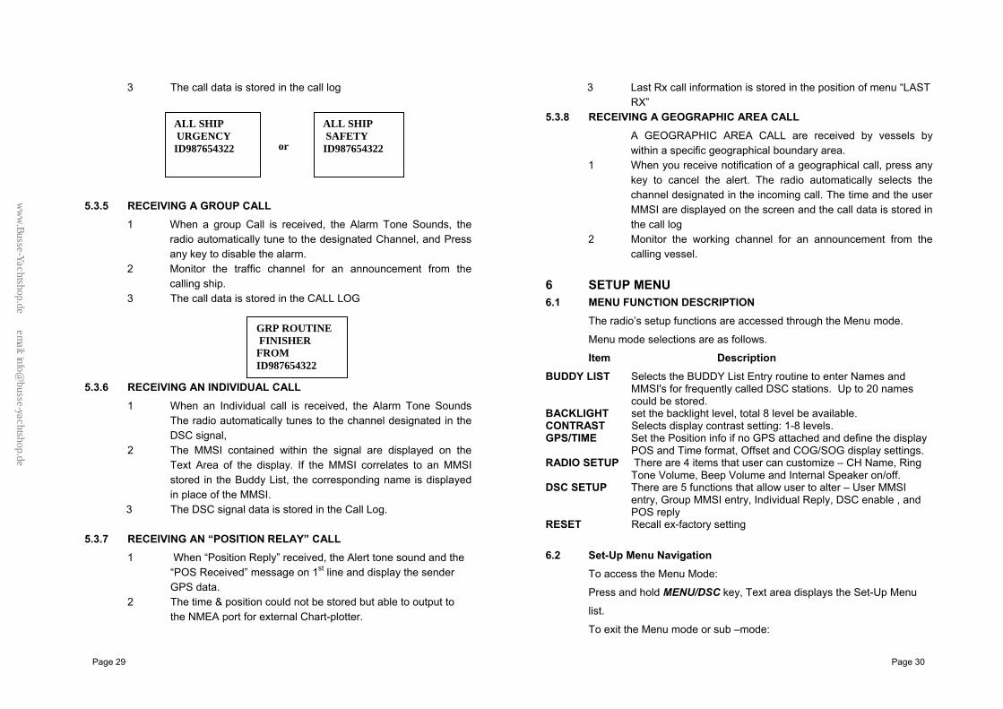
3 The call data is stored in the call log 5.3.5 RECEIVING A GROUP CALL
1 When a group Call is received, the Alarm Tone Sounds, the radio automatically tune to the designated Channel, and Press any key to disable the alarm.
2 Monitor the traffic channel for an announcement from the calling ship.
3 The call data is stored in the CALL LOG
5.3.6 RECEIVING AN INDIVIDUAL CALL
1 When an Individual call is received, the Alarm Tone Sounds The radio automatically tunes to the channel designated in the DSC signal,
2 The MMSI contained within the signal are displayed on the Text Area of the display. If the MMSI correlates to an MMSI stored in the Buddy List, the corresponding name is displayed in place of the MMSI.
3 The DSC signal data is stored in the Call Log. 5.3.7 RECEIVING AN “POSITION RELAY” CALL
1 When “Position Reply” received, the Alert tone sound and the “POS Received” message on 1st line and display the sender GPS data.
2 The time & position could not be stored but able to output to the NMEA port for external Chart-plotter.
3 Last Rx call information is stored in the position of menu “LAST RX”
5.3.8 RECEIVING A GEOGRAPHIC AREA CALL A GEOGRAPHIC AREA CALL are received by vessels by within a specific geographical boundary area.
1 When you receive notification of a geographical call, press any key to cancel the alert. The radio automatically selects the channel designated in the incoming call. The time and the user MMSI are displayed on the screen and the call data is stored in the call log
2 Monitor the working channel for an announcement from the calling vessel.
6 SETUP MENU 6.1 MENU FUNCTION DESCRIPTION
The radio’s setup functions are accessed through the Menu mode.
Menu mode selections are as follows.
Item Description BUDDY LIST Selects the BUDDY List Entry routine to enter Names and
MMSI's for frequently called DSC stations. Up to 20 names could be stored.
BACKLIGHT set the backlight level, total 8 level be available. CONTRAST Selects display contrast setting: 1-8 levels. GPS/TIME Set the Position info if no GPS attached and define the display
POS and Time format, Offset and COG/SOG display settings. RADIO SETUP There are 4 items that user can customize – CH Name, Ring
Tone Volume, Beep Volume and Internal Speaker on/off. DSC SETUP There are 5 functions that allow user to alter – User MMSI
entry, Group MMSI entry, Individual Reply, DSC enable , and POS reply
RESET Recall ex-factory setting
6.2 Set-Up Menu Navigation To access the Menu Mode:
Press and hold MENU/DSC key, Text area displays the Set-Up Menu
list.
To exit the Menu mode or sub –mode:
GRP ROUTINE FINISHER FROM ID987654322
ALL SHIP URGENCY ID987654322
ALL SHIP SAFETY ID987654322 or
ww
w.B
usse-Yachtshop.de em
ail: [email protected]

Page 31 Page 32
Press the 16/9 or CANCEL key or else select the EXIT option from the menu. Rotate the CH knob to select the Item within the Set-Up Menu list To confirm a selected item for adjustment, push the CH knob. When the desired setting is done, press the CH knob to enter the setting, and move back to the Main Menu list. Set Up operation is exited by turning the unit off. All changes are saved in EEPROM (exception Manual Enter GPS Data) During Set-Up operation, TX and RX are available.
6.3 Buddy List The Buddy List can store up to 20 entries with Name and MMSI#. User
can add, edit or delete the record from the list under this submenu. 6.3.1 Adding an Entry
Either use digital keys of hand mike or CH knob entry name and MMSI. To use the CH knob enter way as follow:
1 Select Buddy List and the cursor is at <NEW> press CH knob entry page which prompt up to allow enter Name and MMSI.
2 Rotate the CH knob to select the first desired character (A-Z, 1-9, Space and Back Arrow "<") for the name. When the desired character is shown, push the CH knob to enter, the next characters select all the same, The characters can be up to 12. When the last digit is entered, the activation advances to the first MMSI digit.
3 Enter the MMSI associated with that Buddy name (this must be numeric) Prefix 00 will treat as Coast Once 9 digit be entered, pops up a new page to ask for confirmation to save.
4 Press the CH knob to save the new entry, which is displayed at the top of your BUDDY LIST.
5 Press CANCEL will terminate the process without saving go back to Buddy list page.
6 When the Buddy list is full. you cannot make a new entry until you have delectd an existing entry.
6.3.2 Edit Existing Entry 1 Pick up one from Buddy list and edit Press CH knob one Page
pops up item for you to edit or delete, Choose EDIT. 2 when you are finished editing. Press CH knob into a new page
prompt in to ask for confirmation to save.
3 Press the CH knob to save the new edit. The Buddy list is displayed again. If more changes are required repeat steps1thru 3 otherwise, press cancel to exit.
6.3.3 Delete an entry 1 Select the one which you want to delete from the list. 2 rotate the CH knob to select the delete option.
3 press and hold the he CH knob to confirm the delete action. 4 the selected record will be removed and go back to BUDDY list
page. You can repeat steps from 1to 4 to delete more records, or press cancel to exit.
6.4 BACKLIGHT Adjustment
1 Select BACKLIGHT and press the CH knob. There are 8 levels control for the BACKLIGHT.
2 Rotate the CH knob to adjust the setting, Press the CH knob to permanently enter the setting and return to the MENU LIST.
6.5 CONTRAST Adjustment
1 Select CONTRAST and press the CH knob. There are 8 levels control for the contrast.. The higher numbers the darker LCD
2 Rotate the CH knob to adjust the setting, Press the CH knob to permanently enter the setting and return to the MENU LIST.
6.6 GPS/TIME
The radio automatically detects NMEA strings and decodes appropriate latitude/longitude position and time. If the GPS navigation receiver is not connected on or is not functional, a manual latitude/longitude position and UTC should be entered and used in the DSC distress transmitted message.
BUDDY LIST BACKLIGHT>CONTRAST GPS/TIME
CONTRAST LO HI � � � � � � � �
BUDDY LIST >BACKLIGHT CONTRAST GPS/TIME
BACKLIGHT OFF HI � � � � � � � �
ww
w.B
usse-Yachtshop.de em
ail: [email protected]

Page 33 Page 34
When valid Lat/Lon information is detected, the data is display on the LCD, when there is no valid position information, NO GPS appears.
6.6.1 Manual Enter GPS DATA
If no GPS data is available, POS DATA REQ is displayed, Alarm sounds for 5sec or till any key is pressed.
The manual entry function is just valid if and only if no GPS connected 1 select GPS/TIME then manual 2 enter the latitude, then the longitude, then the UTC. 3 PRESS the CH knob, when all the information is correct. The vessel’s lat/lot with the UTC time are shown on the screen. The
manual entries are cancelled if a real GPS position is received. 6.6.2 Settings
You can also set what time and position information is display on the screen
Whether Position data is displayed Whether the time is displayed Whether a Time Zone Offset is used How the time data is formatted Whether COG/SOG data is displayed
6.6.2.1 Position display on/off
You can choose the position data displayed on the normal mode or not 1. Select GPS/TIME then SETTINGS, then POS DISPLAY
2. Select ON(on) or OFF(off)as desired, this is example, selected on and the screen shows the vessel position.
6.6.2.2 TIME display on/off
You can to turn on/off the time displayed at the normal mode 1 Select GPS/TIME then SETTINGS, then TIME DISPLAY 2 Select ON(on) or OFF(off)as desired, in this example, selected and the
screen no longer shows the time 6.6.2.3 LOCAL TIME (TIME OFFSET)
You can set the add/subtract value from UTC time to equal to local time. When offset value is added, the time will be displayed as LOC instead of UTC First to set the offset direction + or – and then value in ½ hr. step. The updatad result will be displayed immediately
6.6.2.4 TIME FORMAT OPTIONS (TIME FORMAT)
You can choose display time in 12 hr or 24 hr format..
DISTRESS
POS DATA REQ
TIME OFFSET >+1.5 HRS 10:56AM LOC.
TIME FORMAT>12 HR 24 HR 10:56AM LOC.
GPS / TIME >MANUAL SETTINGS
DISTRESS 22 0 28.1111 N 112 0 11.0011 W 08 : 25 UTC
MANUAL POS - - 0 - -.- - - - N - - - 0 - -.- - - - W - - :- -UTC
POS DISPLAY > ON OFF
>POS DISPLAY TIME DISPLAY TIME OFFSET TIME FORMAT
DISTRESS 27º34.1268 N 102º55.5587 W 356º 12.6Ks
TIME DISPLAY ON > OFF
POS DISPLAY >TIME DISPLAY TIME OFFSET TIME FORMAT
COAST GUARD 27045.1234N 112036.5678W
ww
w.B
usse-Yachtshop.de em
ail: [email protected]
Page 35 Page 36
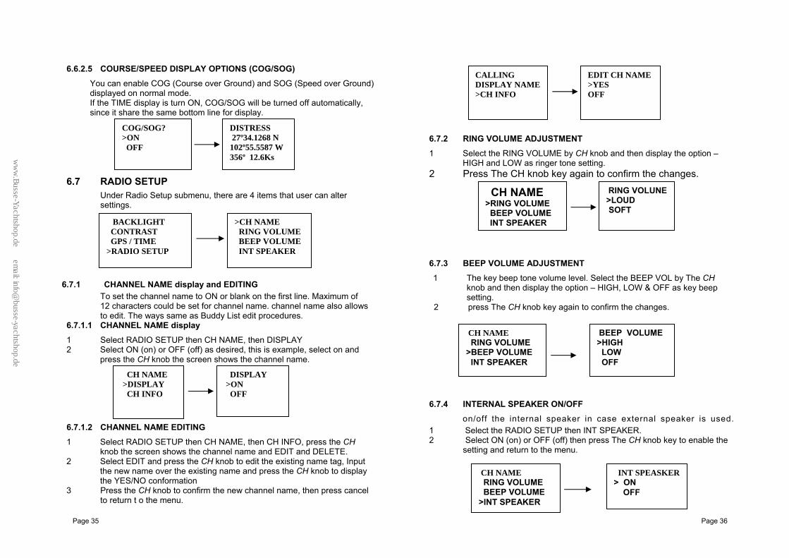
6.6.2.5 COURSE/SPEED DISPLAY OPTIONS (COG/SOG)
You can enable COG (Course over Ground) and SOG (Speed over Ground) displayed on normal mode. If the TIME display is turn ON, COG/SOG will be turned off automatically, since it share the same bottom line for display.
6.7 RADIO SETUP
Under Radio Setup submenu, there are 4 items that user can alter settings.
6.7.1 CHANNEL NAME display and EDITING To set the channel name to ON or blank on the first line. Maximum of 12 characters could be set for channel name. channel name also allows to edit. The ways same as Buddy List edit procedures.
6.7.1.1 CHANNEL NAME display
1 Select RADIO SETUP then CH NAME, then DISPLAY 2 Select ON (on) or OFF (off) as desired, this is example, select on and
press the CH knob the screen shows the channel name. 6.7.1.2 CHANNEL NAME EDITING
1 Select RADIO SETUP then CH NAME, then CH INFO, press the CH knob the screen shows the channel name and EDIT and DELETE.
2 Select EDIT and press the CH knob to edit the existing name tag, Input the new name over the existing name and press the CH knob to display the YES/NO conformation
3 Press the CH knob to confirm the new channel name, then press cancel to return t o the menu.
6.7.2 RING VOLUME ADJUSTMENT
1 Select the RING VOLUME by CH knob and then display the option – HIGH and LOW as ringer tone setting.
2 Press The CH knob key again to confirm the changes. 6.7.3 BEEP VOLUME ADJUSTMENT
1 The key beep tone volume level. Select the BEEP VOL by The CH knob and then display the option – HIGH, LOW & OFF as key beep setting.
2 press The CH knob key again to confirm the changes. 6.7.4 INTERNAL SPEAKER ON/OFF
on/off the internal speaker in case external speaker is used. 1 Select the RADIO SETUP then INT SPEAKER. 2 Select ON (on) or OFF (off) then press The CH knob key to enable the
setting and return to the menu.
DISTRESS 27º34.1268 N 102º55.5587 W 356º 12.6Ks
COG/SOG? >ON OFF
CALLING DISPLAY NAME >CH INFO
EDIT CH NAME>YES OFF
BACKLIGHT CONTRAST GPS / TIME >RADIO SETUP
>CH NAME RING VOLUME BEEP VOLUME INT SPEAKER
CH NAME >RING VOLUME BEEP VOLUME INT SPEAKER
RING VOLUNE>LOUD SOFT
CH NAME >DISPLAY CH INFO
DISPLAY >ON OFF
CH NAME RING VOLUME >BEEP VOLUME INT SPEAKER
BEEP VOLUME>HIGH LOW OFF
CH NAME RING VOLUME BEEP VOLUME >INT SPEAKER
INT SPEASKER> ON OFF
ww
w.B
usse-Yachtshop.de em
ail: [email protected]
Page 37 Page 38
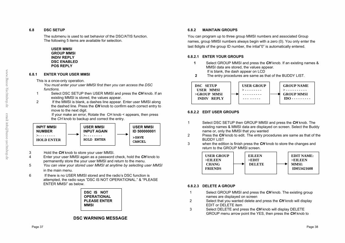
6.8 DSC SETUP
The submenu is used to set behavior of the DSC/ATIS function. The following 5 items are available for selection.
USER MMSI GROUP MMSI INDIV REPLY DSC ENABLED POS REPLY
6.8.1 ENTER YOUR USER MMSI
This is a once-only operation. You must enter your user MMSI first then you can access the DSC functions.
1 Select DSC SETUP then USER MMSI and press the CH knob. If an existing MMSI is stored, the values appear.
2 If the MMSI is blank, a dashes line appear. Enter user MMSI along the dashed line. Press the CH knob to confirm each correct entry to move to the next digit. If your make an error, Rotate the CH knob < appears, then press the CH knob to backup and correct the entry.
3 Hold the CH knob to store your user MMSI. 4 Enter your user MMSI again as a password check, hold the CH knob to
permanently store the your user MMSI and return to the menu. 5 You can view your stored user MMSI at anytime by selecting user MMSI
in the main menu. 6 If there is no USER MMSI stored and the radio’s DSC function is
attempted, the radio says “DSC IS NOT OPERATIONAL.” & “PLEASE ENTER MMSI” as below.
DSC WARNING MESSAGE
6.8.2 MAINTAIN GROUPS You can program up to three group MMSI numbers and associated Group names, group MMSI numbers always begin with a zero (0). You only enter the last 8digits of the group ID number, the intial”0” is automatically entered. 6.8.2.1 ENTER YOUR GROUPS
1 Select GROUP MMSI and press the CH knob. If an existing names & MMSI data are stored, the values appear. If is blank, the dash appear on LCD
2 The entry procedures are same as that of the BUDDY LIST. 6.8.2.2 EDIT USER GROUPS
1 Select DSC SETUP then GROUP MMSI and press the CH knob. The
existing names & MMSI data are displayed on screen. Select the Buddy name or, only the MMSI that you wanted
2 Press the CH knob to edit. The entry procedures are same as that of the BUDDY LIST
3 when the edition is finish press the CH knob to store the changes and return to the GROUP MMSI screen.
6.8.2.3 DELETE A GROUP
1 Select GROUP MMSI and press the CH knob. The existing group names are displayed on screen
2 Select that you wanted delete and press the CH knob will display EDIT or DELETE item
3 Select DELETE and press the CH knob will display DELETE GROUP menu arrow point the YES, then press the CH knob to
DSC IS NOTOPERATIONAL PLEASE ENTER MMSI
USER GROUP >EILEEN CHANG FRIENDS
EDIT NAME: >EILEEN MMSI: ID053421608
EILEEN >EDIT DELETE
DSC SETUP USER MMSI >GROUP MMSI INDIV REPLY
USER GROUP> - - - - - - - - - - - - - - - - - - - - - - - - -
GROUP NAME > - - - - - - - - - - GROUP MMSI IDO - - - - - - - - -
INPIT MMSINUMBER >- - - - - - - - HOLD ENTER
USER MMSIINPUT AGAIN >- - - - - - - - HOLD ENTER
USER MMSIID 500000001 >SAVE CANCEL
ww
w.B
usse-Yachtshop.de em
ail: [email protected]

Page 39 Page 40
empty the group and return to the USER GROUP screen. The LCD displays the group for > - - - - -- - -.
6.8.3 INDIVIDUAL REPLY
You can respond to incoming individual calls with an automatic response or a manual
1 Select DSC SETUP, then INDIV REPLY press the CH knob to display INDIV REPLY MANUAL or AUTOMATIC.
2 Select AUTOMATIC for an automatic response, or MANUAL for a manual response.
3 press the CH knob to confirm your choice and return to the menu.
6.8.4 DSC ENABLE
To temporary turn off the DSC function, such as sailing to inland water or no DSC region.
1 Select DSC SETUP, then DSC ENABLED, Press the CH knob to displays DSC ENABLE ON/OFF.
2 Select OFF for turn off DSC function. 3 press the CH knob to confirm your choice and return to the menu.
6.8.5 POS REPLY
You can set the radio to respond the Position Request. In on of three ways, automatic, manual, off.
1 Select DSC SETUP, then POS REPLY. Then press the CH knob, the
automatic, manual, off appear on the screen. 2 Select your response and press the CH knob to confirm and return to the
menu manual, 6.9 RESET
This feature resets every setting to the factory defaults, except USER MMSI and BUDDY LIST. GROUP MMSI, ATIS MMSI.
1 Select RESET, press CH key, the radios asks for confirmation 2 Select yes, press CH key to reset the radio and return to the
menu.
DSC SETUP USER MMSI GROUP MMSI > INDIV REPLY
INDIV REPLY >MANUAL AUTOMATIC
EILEEN EDIT >DELETE
DELETE GROUP EILEEN >YES NO
USER GROUP > - - - - - - - CHANG FRIENDS
DSC SETUP
GROUP MMSI INDIV REPLY >DSC ENABLED
DSC ENABLE >ON OFF
DSC SETUP INDIV REPLY DSC ENABLED >POS REPLY
POS REPLY
>AUTOMATIC MANUAL OFF
RESET ARE YOU SURE >NO YES
RADIO SETUP DSC SETUP >RESET EXIT
ALL USER SETTINGS RESTORED TO DEFAULTS
ww
w.B
usse-Yachtshop.de em
ail: [email protected]
Page 41 Page 42
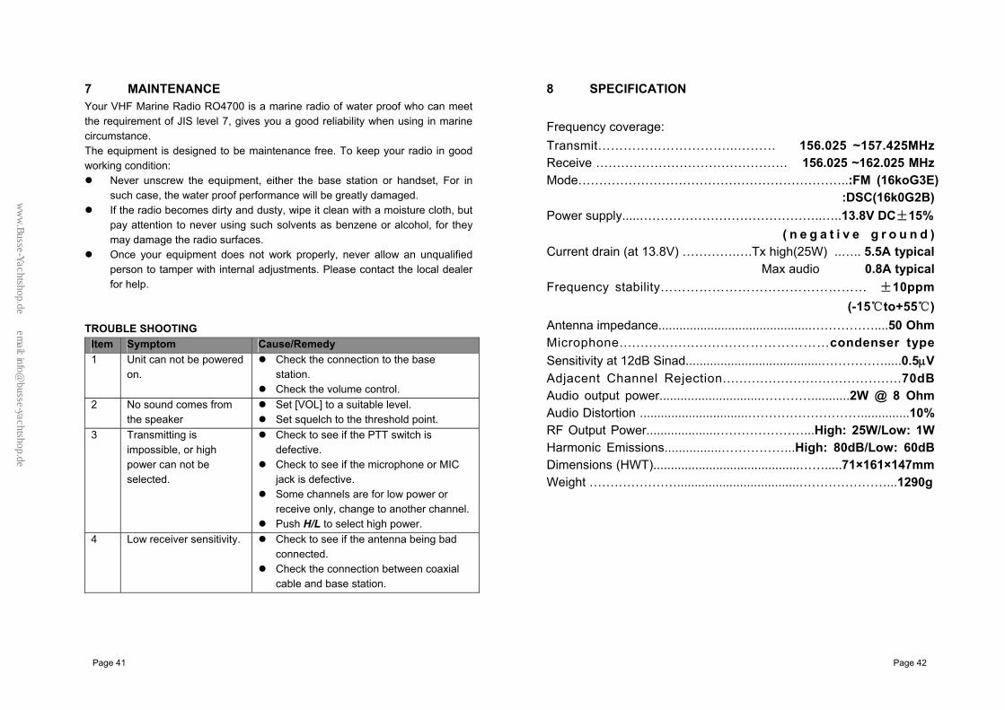
7 MAINTENANCE Your VHF Marine Radio RO4700 is a marine radio of water proof who can meet the requirement of JIS level 7, gives you a good reliability when using in marine circumstance. The equipment is designed to be maintenance free. To keep your radio in good working condition:
Never unscrew the equipment, either the base station or handset, For in such case, the water proof performance will be greatly damaged.
If the radio becomes dirty and dusty, wipe it clean with a moisture cloth, but pay attention to never using such solvents as benzene or alcohol, for they may damage the radio surfaces.
Once your equipment does not work properly, never allow an unqualified person to tamper with internal adjustments. Please contact the local dealer for help.
TROUBLE SHOOTING
Item Symptom Cause/Remedy 1 Unit can not be powered
on. Check the connection to the base
station. Check the volume control.
2 No sound comes from the speaker
Set [VOL] to a suitable level. Set squelch to the threshold point.
3 Transmitting is impossible, or high power can not be selected.
Check to see if the PTT switch is defective.
Check to see if the microphone or MIC jack is defective.
Some channels are for low power or receive only, change to another channel.
Push H/L to select high power. 4 Low receiver sensitivity. Check to see if the antenna being bad
connected. Check the connection between coaxial
cable and base station.
8 SPECIFICATION
Frequency coverage: Transmit…………………………...……… 156.025 ~157.425MHz Receive ………………………………………. 156.025 ~162.025 MHz Mode………………………………………………………..:FM (16koG3E)
:DSC(16k0G2B) Power supply.....……………………………………..…..13.8V DC±15% ( n e g a t i v e g r o u n d ) Current drain (at 13.8V) ………….….Tx high(25W) ..….. 5.5A typical
Max audio 0.8A typical Frequency stability………………………………………… ±10ppm (-15℃to+55℃) Antenna impedance............................................……………....50 Ohm Microphone............................…………………condenser type Sensitivity at 12dB Sinad.......................................…………….....0.5μV Adjacent Channel Rejection................................…........70dB Audio output power.............................…………...........2W @ 8 Ohm Audio Distortion ...............................………………………..............10% RF Output Power....................…………………...High: 25W/Low: 1W Harmonic Emissions................……………...High: 80dB/Low: 60dB Dimensions (HWT)..........................................…….....71×161×147mm Weight …………………...................................…………………...1290g
ww
w.B
usse-Yachtshop.de em
ail: [email protected]

Page 43 Page 44
9 Frequency chart INTL
FREQUENCY(MHz) CHTX RS MODE REMARK
01 156.050 160.650 D
02 156.100 160.700 D
03 156.150 160.750 D
04 156.200 160.800 D
05 156.250 160.850 D
06 156.300 156.300 S
07 156.350 160.950 D
08 156.400 156.400 S
09 156.450 156.450 S
10 156.500 156.500 S
11 156.550 156.550 S
12 156.600 156.600 S
13 156.650 156.650 S
14 156.700 156.700 S
15 156.750 156.750 S * 16 156.800 156.800 S
17 156.850 156.850 S *
18 156.900 161.500 D
19 156.950 161.550 D
20 157.000 161.600 D
21 157.050 161.650 D
22 157.100 161.700 D
23 157.150 161.750 D
24 157.200 161.800 D
25 157.250 161.850 D
26 157.300 161.900 D
27 157.350 161.950 D
28 157.400 162.000 D
60 156.025 160.625 D
61 156.075 160.675 D
62 156.125 160.725 D
63 156.175 160.775 D
64 156.225 160.825 D
65 156.275 160.875 D
66 156.325 160.925 D
67 156.375 156.375 S
68 156.425 156.425 S
69 156.475 156.475 S
70 156.525 156.525 S
71 156.575 156.575 S
72 156.625 156.625 S
73 156.675 156.675 S
74 156.725 156.725 S
75 156.775 156.775 S *
76 156.825 156.825 S *
77 156.875 156.875 S
78 156.925 161.525 D
79 156.975 161.575 D
80 157.025 161.625 D
81 157.075 161.675 D
82 157.125 161.725 D
83 157.175 161.775 D
84 157.228 161.825 D
85 157.275 161.875 D
86 157.325 161.925 D 87 157.375 157.375 S 88 157.425 157.425 S 57/33D/24S
*: Low power(1w) only.
ww
w.B
usse-Yachtshop.de em
ail: [email protected]