
Radio Installations on GMDSS Ships · 2017-10-30 · Radio Installations on GMDSS Ships Guidance...
43
Radio Installations on GMDSS Ships Guidance for Surveyors Notice to all Classification Societies and Radio Surveyors This notice supersedes MSISoo5 Radio Installations on GMDSS Ships. Instructions to Surveyors Summary These guidelines, wherever possible, are based upon the Survey Guidelines Under The Harmonised System Of Survey And Certification adopted by the International Maritime Organization (IMO) through IMO Assembly Resolution A.746(18). Text adopted by the IMO is shown in italics, with a reference to the relevant section of the A.746(18), followed by the interpretation or clarification adopted for radio installations on United Kingdom merchant ships. 1. General Object of instructions These guidelines are issued by the Maritime and Coastguard Agency for the guidance of radio surveyors in the survey and inspection of radio installations on ships for the purpose of ensuring compliance with the various Statutory Instruments covering merchant shipping. They also indicate to shipowners, shipowners' representatives, masters and crew, shipbuilders and radio installation companies the procedure adopted for the survey and acceptance of radio installations. These instructions should be read in conjunction with the instructions issued by the MCA relating to passenger ships, load-line, fire protection, navigational equipment, lifesaving appliances and oil prevention. 1.1 Statutory provisions The principal statutory provisions concerning radio installations are contained in: The Merchant Shipping Act 1995 The Wireless Telegraphy Act 1949 and 1967 The Merchant Shipping (Life-Saving Appliances) for Passenger Ships of Classes III 10 VI(a) 1999 (SI No.2723) The Merchant Shipping (Life-Saving Appliances) for Ships other than ships of Class III to VI(a) 1999 (SI no.2721)
Transcript of Radio Installations on GMDSS Ships · 2017-10-30 · Radio Installations on GMDSS Ships Guidance...
Radio Installations on GMDSS Ships
Guidance for Surveyors Notice to all Classification Societies and Radio Surveyors This notice supersedes MSISoo5 Radio Installations on GMDSS Ships. Instructions to Surveyors
Summary These guidelines, wherever possible, are based upon the Survey Guidelines Under The Harmonised System Of Survey And Certification adopted by the International Maritime Organization (IMO) through IMO Assembly Resolution A.746(18). Text adopted by the IMO is shown in italics, with a reference to the relevant section of the A.746(18), followed by the interpretation or clarification adopted for radio installations on United Kingdom merchant ships.
1. General
Object of instructions
These guidelines are issued by the Maritime and Coastguard Agency for the guidance of radio surveyors in the survey and inspection of radio installations on ships for the purpose of ensuring compliance with the various Statutory Instruments covering merchant shipping. They also indicate to shipowners, shipowners' representatives, masters and crew, shipbuilders and radio installation companies the procedure adopted for the survey and acceptance of radio installations. These instructions should be read in conjunction with the instructions issued by the MCA relating to passenger ships, load-line, fire protection, navigational equipment, lifesaving appliances and oil prevention.
1.1 Statutory provisions
The principal statutory provisions concerning radio installations are contained in:
The Merchant Shipping Act 1995
The Wireless Telegraphy Act 1949 and 1967
The Merchant Shipping (Life-Saving Appliances) for Passenger Ships of Classes III 10 VI(a) 1999 (SI No.2723)
The Merchant Shipping (Life-Saving Appliances) for Ships other than ships of Class III to VI(a) 1999 (SI no.2721)
The Merchant Shipping (Radio Installations) Regulations 1998 (SI 1998 No. 2510)
The Merchant Shipping (Categorisation of Waters) Regulations 1992 (SI 1992 No. 2356)
The Merchant Shipping (Survey and Certification) Regulations 1995 (SI 1995 No. 1210)
The Merchant Shipping (High Speed Craft) Regulations 1996 (SI 1996 No. 3188)
A comprehensive list of current Merchant Shipping acts and Regulations is issued at regular intervals and published by the MCA in the form of a Marine Guidance Note.
1.2 Definitions
In these guidelines the following definitions apply:
Basic Equipment
Equipment forming part of the radio installations provided on a ship to comply with regulation 8, 9, 10, 11 and 12, as appropriate, of the Radio Installation Regulations (q.v.).
Certifying Body
An Organisation authorised or recognised by the Secretary of State to perform the survey of radio installations on United Kingdom ships and, as appropriate, issue Certification.
Contractor
An Organisation appointed by the Secretary of State to perform Radio Surveys, Inspections and a Radio Advisory Service on behalf of the MCA.
DSC
Digital Selective Calling
Duplicate Equipment
Equipment, additional to basic equipment (q.v.), forming part of radio installations provided on a ship to comply with regulation 15(6) of the Radio Installation Regulations (q.v.).
Emergency Position-Indicating Radio Beacon (EPIRB)
A station in the mobile service, the emissions of which are intended to facilitate search and rescue operations.
Existing Installation
An installation wholly installed on board a ship before the date on which the present Convention enters into force irrespective of the date on which acceptance by the respective Administration takes effect; or,

An installation part of which was installed on board a ship before the date of entry into force of the present convention and the rest of which consists either of parts installed in replacement of identical parts, or parts which comply with the requirements of this chapter.
Float Charging
A battery-charging arrangement where a battery, and all equipment connected to the battery, are simultaneously supplied with electrical energy from an automatic charging device.
Functional Requirements
The functional requirements of the GMDSS as specified in regulation 4 of Chapter IV of the Safety Convention (q.v.).
GMDSS
The Global Maritime Distress and Safety System.
GOC
General Operator’s Certificate
HF
The radio frequencies between 4 and 30 MHz allocated by the ITU (q.v.) to the maritime mobile services.
IMO
International Maritime Organization 4, Albert Embankment London SE1 7SR
Tel +44 0207 735 7611
Initial Survey
The complete inspection, before a ship is put into service, of all the items relating to a particular certificate to confirm that the relevant requirements are complied with and that these items are satisfactory for the service for which the ship is intended.
INMARSAT
The Organisation established by the Convention of the International Maritime Satellite Organisation (INMARSAT) adopted on 3 September 1976.
INMARSAT Ltd. 99 City Road London EC1Y 1AX
Tel +44 0207 728 1000

International NAVTEX Service
The co-coordinated broadcast and automatic reception on 518 kHz of maritime safety information by means of narrow-band direct-printing telegraphy using the English language.
ITU
International Telecommunication Union (ITU) Places des Nations CH-1211 Geneva 20 Switzerland
Marine Guidance Notice
A notice described as such and issued by the Maritime and Coastguard Agency.
Maritime Safety Information (MSI)
Navigational and meteorological warnings, meteorological forecasts and other urgent safety related messages broadcast to ships.
Merchant Shipping Notice
A notice described as such and issued by the Maritime and Coastguard Agency; and any reference to a particular Merchant Shipping Notice includes a reference to any document amending or replacing that Notice which is considered by the Secretary of State to be relevant from time to time and is specified in a Merchant Shipping Notice.
MF
The radio frequencies less than 4 MHz allocated by the ITU (q.v.) to the maritime mobile services.
MCA
The Maritime and Coastguard Agency (MCA), an Executive Agency of the Department for Transport.
Navigation Safety Branch
Branch of the Standards Directorate of the MCA.
Survey and Inspection Branch
A Branch of the Operations Directorate of the MCA.
Seafarer Standards & Training
Branch of the Quality and Standards Directorate of the MCA.
New Installation
Any installation which is not an existing installation.

Radio Operator
A person holding a certificate specified in the Radio Regulations (ITU) (q.v.) as appropriate.
Radio Regulations (ITU)
The Radio Regulations annexed to, or regarded as being annexed to, the most recent International Telecommunication Convention which may be in force at any time.
Radio Installations Regulations
The Merchant Shipping (Radio Installations) Regulations 1998, as may be amended from time to time.
Regulations
Collectively or individually, those regulations regarding radio matters that are applicable to the vessel involved.
Renewal Survey
An inspection of the items relating to the particular certificate to confirm that they are in a satisfactory condition and for the service for which the ship is intended leading to the issue of a new certificate.
Safety Convention Ship
Any ship granted a certificate or certificates in accordance with the provisions of the "Safety of Life at Sea (SOLAS) Convention".
1.3 Application of the Radio Installations Regulations
1.3.1 Ships to which the Radio Installations Regulations apply
The Radio Installations Regulations apply to:
-Sea-going United Kingdom ships. -Other seagoing ships while they are in the United Kingdom or the territorial waters thereof.
1.3.2 Ships to which the Radio Installations Regulations do not apply
The Radio Installations Regulations do not apply to:
-Troopships not registered in the United Kingdom. -Ships not propelled by mechanical means. -Pleasure craft. -Fishing vessels. -Cargo ships of less than 300 tons. -United Kingdom ships while they are being navigated within the Great lakes Of North America and their connecting and tributary waters as far east as the lower exit of the St. Lambert Lock at Montreal in the Province of Quebec, Canada. -High Speed Craft to which the Merchant Shipping (High-Speed Craft) Regulations 1996 apply.

Note: Fishing vessels, high speed craft and certain other vessels engaged on commercial operations may be subject to separate requirements relating to the provision of radio installations. These instructions may be referred to when performing surveys or inspections of these radio installations.
1.4 Recommended practices
Recommended practices concerning radio installations for merchant ships are contained in:
-Code of Safe Working Practices for Merchant Seamen -Code of Practice for Noise Levels in Merchant Ships -The IEE Regulations for the Electrical Equipment of Ships -Merchant Shipping Notices -Marine Guidance Notices -Marine Information Notes -British Standard Specification for Limits and methods electromagnetic interference generated by marine equipment and installations. (BS 1597: 1985) -Code of practice for radio interference suppression on marine installations (BS 5260): 1975 Confirmed Nov 1981)
1.5 Powers of surveyors
Powers of surveyors are derived from:
-The Merchant Shipping Act 1995 (Section 256)
1.5.1 Surveyors - Terms of Reference
A Radio Surveyor appointed by the Secretary of State for Transport may under Sections 256 of the Merchant Shipping act 1995, inspect a vessel and, where appropriate, confirm that it is properly provided with radio installations and satisfies the other requirements in conformity with the Regulations.
A Radio Surveyor, whilst undertaking work on behalf of the Maritime and Coastguard Agency shall not:
-offer comments concerning individual suppliers of marine radio equipment or their capabilities in respect of repairs nor be personally involved in any repairs which may need to be carried out in connection with that survey; -undertake any sales activity whatsoever, whether at a Regional office or Main Office, in connection with any survey or inspection performed; -pass any information whatsoever regarding a potential sale or sales connected with any survey or inspection performed, to any third party (except the MCA for monitoring purposes) or to any person or Department within the surveyor's parent company.
1.5.2 Referral to Maritime and Coastguard Agency
Should a difficulty arise in an area covered by the Regulations, Merchant Shipping Notices, Marine Guidance Notices or these Instructions the matter should be referred to the:
Maritime and Coastguard Agency Navigation Safety Branch Spring Place 105 Commercial Road Southampton SO15 1EG

Tel: +44 (0) 023 80329 521
Fax: +44 (0) 023 80329 204
E-mail: [email protected]
1.6 Detention
In cases where a ship to which the regulations apply, does not comply with the relevant Regulations, the ship shall be liable to be detained.
Section 95 of the Merchant Shipping Act 1995 as amended provides for the detention of an unsafe ship. Guidance on detention is contained in MCA Instructions to Surveyors, Survey and Inspection Policy. In the event of a ship not complying with the regulations, the Radio Surveyor must consult with the local MCA Surveyor in charge who will determine whether the vessel should be detained and what further action should be taken against the vessel.
When a ship not registered in the UK is detained, a copy of the detention order should be forwarded as soon as possible to the Consul or Marine Administration of the country in which the ship is registered plus a copy to Survey and Inspection Branch.
1.7 Improvement and Prohibition Notices
1.7.1 General
Detention is effective if the ship is about to go to sea, and is mainly used to prevent departure of a ship until defects affecting her safety have been remedied. It is not appropriate for stopping unsafe practices or preventing dangerous activities in port, and in some cases it is too severe a course of action to deal with some infringements of statutory requirements. An alternative course of action is available under the Merchant Shipping Act 1995, which allows the serving of Improvement and Prohibition Notices.
1.7.2 Improvement Notices
An Improvement Notice can be issued where there is a breach of any of the statutory provisions listed in the Merchant Shipping Act 1995 or if it is believed that a contravention has occurred and is likely to be repeated. It is aimed at preventing accidents; injury or pollution by ensuring something is put right rather than punishment through prosecution. An Improvement Notice requires that the person on whom it is served must comply fully with the remedy described on the notice by a date specified in the notice.
1.7.3 Prohibition Notices
A Prohibition Notice may be used to stop or prohibit an activity if that activity involves a risk of serious personal injury or serious pollution. Unlike an Improvement Notice, a Prohibition Notice can have immediate effect and is therefore the appropriate instrument for use against imminent risk. The issue of a Prohibition Notice will mean the stopping of an activity, which in turn may delay the sailing of a ship. Consequently the decision to issue such a Notice should be given the same careful consideration as the issue of an Order of Detention.
1.7.4 Non-United Kingdom Ships

In general, United Kingdom Regulations require standards on non-United Kingdom ships to be equivalent to those on United Kingdom ships and make provisions for measures to be taken to rectify any deficiencies or, in extreme cases, for ships to be detained. Where an activity involves a risk of serious injury or pollution a Prohibition Notice can be issued to a non-United Kingdom ship provided the activity involved is one to which relevant statutory instruments apply. However an Improvement Notice can be issued only where there is a breach of specific regulation and the surveyor should first satisfy himself that the regulation involved does in fact apply to non-United Kingdom ships.
1.8 Exceptions
1.8.1 Application for Exemptions
The Secretary of State for Transport is empowered to exempt any merchant ship from any of the requirements of the Regulations. Applications for exemption may be sent by the owners or their representatives to the Maritime and Coastguard Agency's Navigation Safety Branch, or through the Chief Surveyor at the Local marine Office. Any such application should contain detailed reasons for regarding the statutory requirements as unnecessary or unreasonable. Applications received by District Chief Surveyors should be forwarded to the Navigation Safety Branch for a decision.
1.8.2 Issue of Exemption Certificate
If complete, partial or conditional exemption is granted by the MCA, an Exemption Certificate will be issued to the applicant stating the extent of the exemption, and where appropriate, the conditions upon which it has been granted. Exemption Certificates will not normally be valid for more than 12 months, and where possible, will remain in force for the same period as any certificate relating to the Radio Installation. A copy of any Exemption Certificate shall be retained aboard the vessel to which it is granted and must be made available to a Radio Surveyor or MCA Surveyor at any Survey or Inspection of the Radio station.
1.8.3 Non-UK Registered Ships
Where a safety Convention Ship not registered in the United Kingdom holds an Exemption Certificate, the Radio Surveyor or MCA Surveyor should check that the exemption falls within the terms of the Safety Convention as specified in IMO Circular SL.14/Circ.115 issued 21 June 1993. Where there is reason to doubt the extent of the exemption, the matter should be referred to the local Surveyor in Charge.
1.9 Fees
The fees for the surveys of ships are contained in the current Merchant Shipping (Fees) Regulations.
1.10 Safety
To confirm that personnel are not placed at risk or equipment is not inadvertently damaged during survey, a responsible person representing the owners, capable of operating the equipment should be present during survey or other inspection of radio installations. If the owner is not so represented the Surveyor should not proceed unless he is satisfied that it is safe to do so and has the agreement of the master or representative of the shipowner.
2. Survey Arrangements

2.1 Application for radio survey
Application for a survey should be made in accordance with Marine Guidance Notice 286. A Contractor has been appointed by the MCA to conduct the surveys of radio installations on UK registered ships and acts on the Agency's behalf in issuing Convention Certificates to UK registered cargo ships and non-UK registered cargo ships in UK ports. The Contractor is required to take full legal responsibility for the actions of the Radio Surveyors supplied.
In any application for an initial survey clear instructions should be given to the certifying body regarding the GMDSS sea area or areas through which the ship will pass during its intended voyage(s).
Where any change to the equipment and other items covered by the survey is to be made or has been made prior to a renewal survey, or where it is intended to amend the area or area(s) of operation on the certificate, this information should be brought to the attention of the certifying body at the time of application.
Radio surveyors may be required, as necessary; to perform a survey of the radio installations on a UK registered ship overseas. Initial surveys of UK registered ships are to be performed by the contractor unless alternative arrangements have been approved by Navigation Safety Branch. With the exception of UK registered passenger ships, which must be surveyed by the contractor, renewal surveys may be conducted locally in foreign ports as described in Marine Guidance note 286.
Radio Surveyors performing surveys for statutory purposes should confirm that all the equipment required under the Regulations is carried and is fit and ready for use, that the installation is in accordance with the Regulations and Instructions and that all radio operators are appropriately qualified.
2.2 Submission of drawings (plans & designs)
Shipowners and shipbuilders should submit plans and particulars of the proposed radio installations for new ships to Navigation Safety Branch or to the Contractor appointed by the MCA to conduct the surveys of radio installations on the Agency's behalf at the design stage. This will provide an early opportunity to determine; as far as possible, whether the proposals comply with the Regulations; they should cover the layout of equipment, wiring and antenna arrangements. These plans will be treated in confidence.
2.3 Issue of Certificates
If entirely satisfied that the applicable Regulations are being met and all fees due have been paid, the Radio Surveyor should complete and forward a Declaration of Radio Survey as follows:
-in the case of a passenger ship, to the MCA Lead Surveyor for use in connection with the issue of a Passenger Certificate; -in the case of a cargo ship, to the Contractor above, who will issue the Safety Radio Certificate.
Note: "Electronic" means may be used to forward Declarations of Survey over the telecommunications network.
2.4 Deficient installations
When a Radio Surveyor considers an installation deficient or defective, a notice in writing is to be handed or sent to the owner or his representative pointing out the defect or deficiency and indicating what is required to remedy it. All defects and deficiencies must be made good to the satisfaction of

the Radio Surveyor. If through non-compliance, a Declaration of Survey cannot be issued, or if it should be considered necessary to invoke further enforcement action, the local Regional Chief Surveyor must be informed.
3. Guidelines for Survey
3.1 Application
Radio equipment installed on a SOLAS ships should meet the relevant IMO requirements and ITU recommendations and should be of a type approved by the administration.
These Guidelines are applicable when installing GMDSS radio equipment on board SOLAS ships.
The rules in these guidelines also apply to radio installations on mobile offshore drilling units as prescribed in the MODU code.
(See chapter 11 for GMDSS requirements offshore)
Cargo ships of less than 300 gross tonnage (gt) and fishing/catching vessels are as a general rule not covered by SOLAS requirements. However, if such ships/vessels are going to install GMDSS radio equipment on a voluntary basis or mandatory basis according to national laws, these guidelines should be followed as far as practicable.
These guidelines reflect to a large extent unambiguous requirements in accordance with the relevant rules and regulations, see subsection 3.2. below. Other practical installation solutions than the ones emerging from these guidelines may, however, be accepted as long as the international requirements as laid down in the SOLAS Convention etc are met and the installation is considered to be equivalent.
Note: - The marine electronics company which installs the radio equipment should be responsible for giving the radio operators proper familiarisation in the use of the installed radio equipment before it is put into operation.
3.2 Rules and regulations
These guidelines are prepared in accordance with the following conventions, regulations, instructions and guidelines:
SOLAS 1974 as amended
IMO Resolutions (Performance standards) and IMO Circulars ITU (International Telecommunication Union) Radio Regulations (RR) International Standards – ISO 14612:2004 The STCW Convention (Standard of Training, Certification and Watchkeeping)
3.3 Drawings (plans and designs)
For the radio installations, including those used in lifesaving appliances, the examination of plans and designs should consist of:

- establishing:
• the sea areas declared for operation. • the equipment installed to fulfil the functional requirements for the sea areas. • the methods used to confirm the availability of the functional requirements. • the arrangements for supply of an emergency source of energy (if any).
Declarations are required from the owner, the owner's representative or the shipyard as appropriate relating to the following:
• The sea area or sea areas through which the ship will operate. • The radio installations fulfilling the functional requirement. • The method or methods adopted to ensure the radio equipment required by the Radio
Installations Regulations complies with the serviceability and maintenance requirements of these regulations.
• The availability, or otherwise, of an emergency supply conforming with the Merchant Shipping (Passenger Ship Construction and Survey) Regulations 1984, as amended, or the Merchant Shipping (Cargo Ship Construction and Survey) Regulations 1984, as amended and as appropriate relating to the requirements to supply the radio installations.
3.3.1 General
Specified drawings (plans of the radio installation) should available well before the work on a new building or reconstruction of ships or offshore units is started. Insufficient or missing drawings may result in deficiencies during radio survey and could lead to expensive repairs costs later. (Resolution A. 746(18) item 8)
For the radio installation the following drawings should be prepared:
1. Antenna drawing
2. Radio arrangement drawing
3. Wiring diagram
For new buildings the antenna and radio arrangement drawings should at least be of size 1:50.
Approved “as installed” wiring diagram, radio arrangement as well as antenna drawings should be kept available on board the ship for presentation during radio survey etc.
3.3.2 Antenna drawings
Antenna drawings should show all antennas seen from fore or aft position, the port or starboard position and from above. This applies to the following antennas:
1. All transmitting antennas including location of antenna tuner
2. All receiving antennas including GNSS antennas
3. Radar antennas
4. Satellite communication antennas

5. The location of float-free EPIRBs
6. AIS antennas
3.3.3 Changes in the antenna arrangement
When changes are made in the antenna arrangement, modified antenna drawings should be prepared.
3.3.4 Radio arrangement drawings (Lay-out of bridge and communication room)
These drawings should show the location of the following equipment:
1. Controllers for transmitting distress alerts
2. VHF radio installations, including any control units
3. MF or MF/HF installation, including any control units, NBDP printers etc.
4. Satellite communication equipment, including terminals, printers etc.
5. Watchkeeping receivers for VHF ch. 70, 2187.5 kHz, and HF distress channels in 4, 6, 8, 12 and 16 MHz bands
6. NAVTEX and EGC receivers
7. Radar transponders and EPIRBs (if located on the navigating bridge)
8. Hand held (two-way) GMDSS VHF transceivers and their chargers
9. Emergency light powered from a reserve source of energy to illuminate the mandatory radio equipment
10. Battery charger (for the reserve source of energy)
11. Fuse box.
3.3.5 Wiring diagram
These drawings should show the following connections etc:
1. Antenna connections
2. Connections to telephone exchange (PABX), fax machine etc.
3. Connections to the ships mains, emergency source of energy, and the reserve source of energy (batteries), and switching systems for all radio- and radio navigation equipment
4. Which radio equipment (including emergency light) being connected to each power unit/source
5. Fuses for all radio equipment
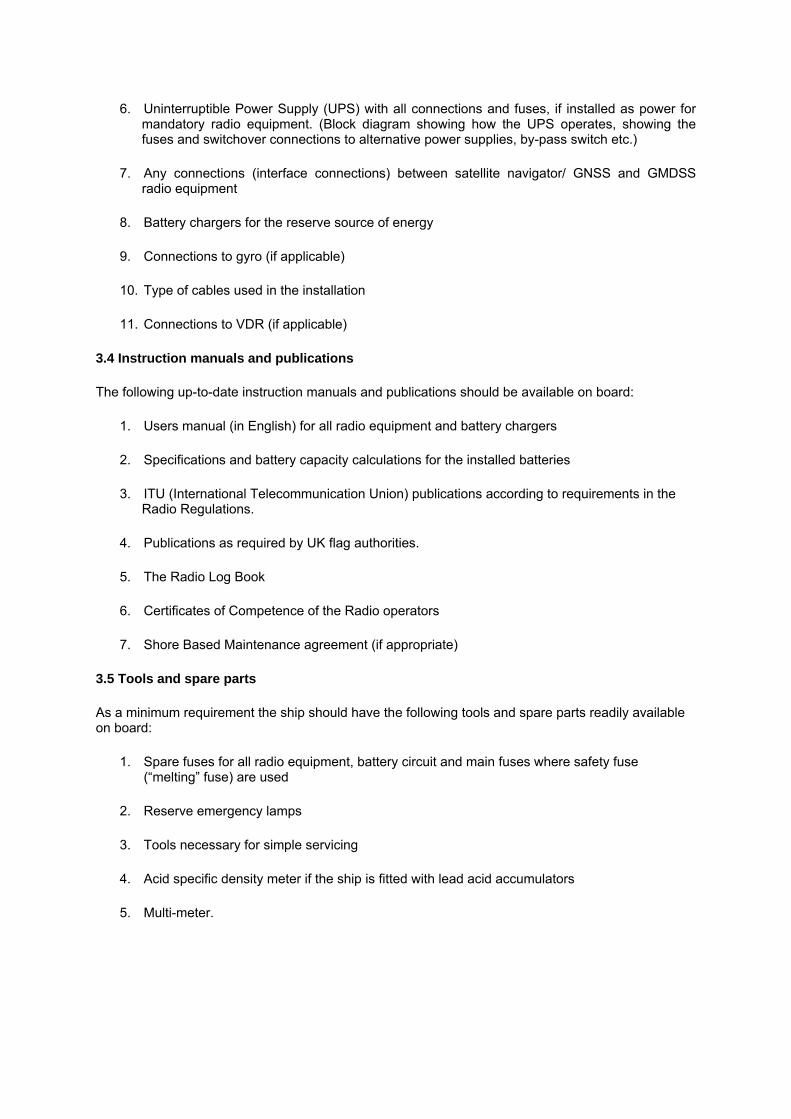
6. Uninterruptible Power Supply (UPS) with all connections and fuses, if installed as power for mandatory radio equipment. (Block diagram showing how the UPS operates, showing the fuses and switchover connections to alternative power supplies, by-pass switch etc.)
7. Any connections (interface connections) between satellite navigator/ GNSS and GMDSS radio equipment
8. Battery chargers for the reserve source of energy
9. Connections to gyro (if applicable)
10. Type of cables used in the installation
11. Connections to VDR (if applicable)
3.4 Instruction manuals and publications
The following up-to-date instruction manuals and publications should be available on board:
1. Users manual (in English) for all radio equipment and battery chargers
2. Specifications and battery capacity calculations for the installed batteries
3. ITU (International Telecommunication Union) publications according to requirements in the Radio Regulations.
4. Publications as required by UK flag authorities.
5. The Radio Log Book
6. Certificates of Competence of the Radio operators
7. Shore Based Maintenance agreement (if appropriate)
3.5 Tools and spare parts
As a minimum requirement the ship should have the following tools and spare parts readily available on board:
1. Spare fuses for all radio equipment, battery circuit and main fuses where safety fuse (“melting” fuse) are used
2. Reserve emergency lamps
3. Tools necessary for simple servicing
4. Acid specific density meter if the ship is fitted with lead acid accumulators
5. Multi-meter.

If the ship makes use of the “on board maintenance” method, it should be equipped with extensive test equipment and spare parts, which enable maintenance and repairs of all mandatory radio equipment while at sea.
3.6 Maintenance requirements
Ships equipped with GMDSS radio installation should meet specific requirements as to maintenance methods for the radio installation. Irrespective of sea areas, the ship should not leave harbour without being able to transmit distress alert ship-to-shore by at least two separate and independent radio communication systems.
(SOLAS 1974, as amended, chapter IV/4.1)
SOLAS ships in sea areas A1 and A2 are required to use at least one of the three specific maintenance methods, whereas convention ships in areas A3 and A4 should use a combination of two methods.
(SOLAS 1974, as amended, chapter IV.15 and IMO resolution A.702(17))
3.6.1 Shorebased maintenance
1. The shipping company/ship may have a written agreement with a marine electronic company or be able to present a written declaration/plan showing how shore-based maintenance is to be carried out. (IMO resolution A.702(17), Annex, item. 3)
2. A Radio Safety Certificate issued by an Administration should, in general, be a sufficient proof that satisfied adequate maintenance arrangement has been made. (IMO resolution, A.702(17) and Com/circ. 117)
3.6.2 At sea electronic maintenance
If the shipowner chooses at-sea electronic maintenance, personnel with necessary qualifications and authorisation for servicing the equipment must be present on board. All necessary instruments and spare parts for repair of all radio equipment must also be available when the ship is at sea.
(IMO resolution. A.702(17))
3.6.3 Duplication of equipment
The following additional equipment should be installed in sea areas A3 and A4:
1. VHF with DSC controller
2. Approved satellite ship earth station or complete MF/HF radio telephony station with DSC and NBDP (See note).
(IMO resolution A.702(17))
Note: - Ships in the A3 sea areas may choose between duplication with either complete MF/HF transceiver or approved satellite ship earth station. Ships in regular trade in sea areas A4 must duplicate with a complete MF/HF installation. Ships in sea area A4 which are not in regular trade in

that area may duplicate with approved satellite ship earth station, provided a MF/HF installation is used as main station.
3.7 Ship Station Radio License
1. A ship station radio licence in accordance with the Radio Regulations should be issued to the ship.
2. The licensee (normally the shipowner) is responsible for applying for a radio licence in due time before the installation take place.
(RR. Art. 18)
Note: - The Maritime Mobile Service Identity (MMSI) number stipulated in the radio licence should be coded into the DSC equipment, and if appropriate also into the satellite EPIRB. If the national authority accept serial number or call sign for identification of EPIRBs, the correct serial number or call sign must be coded into the EPIRB.
All these identities must be changed when a ship is transferred to another flag and appropriate steps taken to ensure databases held ashore are kept current.
3.8 Application for activation of satellite equipment
The licensee is also responsible for registration and service activation of satellite ship earth station.
3.9 De-activation of satellite equipment when transferring a ship to foreign flag
When transferring a ship to foreign flag, the licensee/shipowner must inform the appropriate Licensing Authority immediately concerning de-activation of satellite equipment.
3.10 Initial and annual radio survey, issuance, renewal and endorsement of Safety Radio Certificates
Survey of radio installation on SOLAS ships should be carried out in accordance with the rules laid down in IMO Res. A.746(18) “Survey Guidelines under the harmonised system of survey and certification” R 8 (adopted by IMO), and SOLAS 1974 as amended, chapter I, part B. It is important to note the following text in this resolution:
.1 The radio survey should always be performed by a fully qualified radio surveyor who has adequate knowledge of the IMO’s relevant Convention, particularly SOLAS and associated performance standards and appropriate ITU Radio Regulations. The radio survey should be carried out using suitable test equipment capable of performing all relevant measurements required by these guidelines.
.2 It is considered as very important that the responsible radio operators (holding a General Operators Certificate GOC or ROC certificate) are properly instructed and trained in how to use the GMDSS radio equipment.
.3 The International Convention of Training, Certification and Watch keeping of Seafarers (STCW 1995) requires that the radio operator performing watch-keeping duties should:
1. ensure that watch is maintained on the frequencies specified in the Radio Regulations and SOLAS Convention; and

2. while on duty, regularly check the operation of the radio equipment and its sources of energy and report to the master any failure of this equipment.
3. The radio licence and certificate for the radio operator/operators should be checked during the survey.
4. Functional requirements
4.1 General
1. The functional Requirements of the GMDSS are detailed in SOLAS chapter IV, regulation 4. The most important requirement is that “Every ship, while at sea, should be capable of transmitting ship-to-shore distress alerts by at least two separate and independent means each using a different radio communication service”. It should be possible to initiate such alerts from the position from which the ship is normally navigated.
2. Under certain conditions the satellite EPIRB may be used to meet this requirement if installed close to the navigation bridge or if it can be remote activated from the bridge.
3. In addition to the above mentioned requirements, it should be possible to initiate the transmission of DSC distress alerts from the navigation bridge on VHF, and also on MF or HF, provided that the MF or HF equipment is obligatory in the trade area of the ship. (SOLAS, chapters IV/8 and 9)
4. All ships should keep continuous watch on VHF channel 70 by use of a Digital Selective Calling (DSC) receiver.
5. Ships with MF requirements should in addition keep continuous watch on MF DSC 2187,5 kHz and on HF DSC distress and safety channels if required to have HF radio equipment installed (see also subsection 4.2.4 and 4.2.5).
6. IMO has at MSC 75 and in accordance with resolution MSC.131(75) decided to require all vessels to maintain, when practical, a continuous listening watch on VHF channel 16 until such time as the Maritime Safety Committee may determine the cessation of this requirement.
Watch should also be kept with NAVTEX and/or with Enhanced Group Calling (EGC) receiver.
4.2 Sea areas (definitions)
1. A1 means an area within the radiotelephone coverage of at least one VHF coast station in which continuous DSC alerting is available, as may be defined by a Contracting Government.
2. A2 means an area, excluding sea area A1, within the radiotelephone coverage of at least one MF coast station in which continuous DSC alerting is available, as may be defined by a Contracting Government.
3. A3 means an area, excluding sea areas A1 and A2, within the coverage of an INMARSAT geostationary satellite in which continuous alerting is available (76 °N and 76 °S).

4. A4 means an area outside sea areas A1, A2 and A3.
4.3 Equipment requirements (including duplication of equipment) for SOLAS ships
4.3.1 GMDSS equipment requirements in force for all passenger ship in international trade as well as cargo ships of 300 gt. and upwards in international trade: (SOLAS 1974, as amended, chapter IV and IMO resolution A.702(17))
Equipment
A1 A2 A3 INMARSAT solution
A3 HF solution
A4
VHF with DSC X X X X X DSC watch receiver channel 70 X X X X X MF telephony with MF DSC X X DSC watch receiver MF 2187,5 kHz X X INMARSAT ship earth station with EGC receiver X MF/HF telephony with DSC and NBDP X X DSC watch receiver MF/HF X X Duplicated VHF with DSC X X X Duplicated INMARSAT Ship to Earth Station (SES) X X Duplicated MF/HF telephony with DSC and NBDP X NAVTEX receiver 518 kHz X X X X X EGC receiver X1 X1 X X Float-free satellite EPIRB X X X X X4 Radar transponder Search and Rescue Transponder (SART)
X2 X2 X2 X2 X2
Hand held GMDSS VHF transceivers X3 X3 X3 X3 X3 For passenger ships the following applies from 01.07.97 “Distress panel” (SOLAS chapter IV/6.4 and 6.6) X X X X X Automatic updating of position to all relevant radiocommunication equipment chapter IV/6.5. This also applies for cargo ships from 01.07.02 (chapter IV, new regulation 18)
X X X X X
Two-way-on-scene radiocommunication on 121,5 or 123,1 MHz from the navigating bridge.(SOLAS chapter IV/7.5)
X X X X X
1)Outside NAVTEX coverage area.
²)Cargo ships between 300 and 500 gt.: 1 set. Cargo ships of 500 gt. and upwards and passenger ships: 2 sets.
³)Cargo ships between 300 and 500 gt.: 2 sets. Cargo ships of 500 gt. and upwards and passenger ships: 3 sets.
4)INMARSAT E-EPIRB cannot be utilised in sea area A4.
5. Basic equipment - supplementary requirements
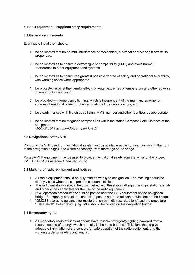
5.1 General requirements
Every radio installation should:
1. be so located that no harmful interference of mechanical, electrical or other origin affects its proper use.
2. be so located as to ensure electromagnetic compatibility (EMC) and avoid harmful interference to other equipment and systems.
3. be so located as to ensure the greatest possible degree of safety and operational availability, with warning notice when appropriate.
4. be protected against the harmful effects of water, extremes of temperature and other adverse environmental conditions.
5. be provided with emergency lighting, which is independent of the main and emergency sources of electrical power for the illumination of the radio controls; and
6. be clearly marked with the ships call sign, MMSI number and other identities as appropriate.
7. be so located that no magnetic compass lies within the stated Compass Safe Distance of the equipment. (SOLAS 1974 as amended, chapter IV/6.2)
5.2 Navigational Safety VHF
Control of the VHF used for navigational safety must be available at the conning position (in the front of the navigation bridge), and where necessary, from the wings of the bridge.
Portable VHF equipment may be used to provide navigational safety from the wings of the bridge. (SOLAS 1974, as amended, chapter IV.6.3)
5.3 Marking of radio equipment and notices
1. All radio equipment should be duly marked with type designation. The marking should be clearly visible when the equipment has been installed.
2. The radio installation should be duly marked with the ship's call sign, the ships station identity and other codes applicable for the use of the radio equipment.
3. DSC operation procedures should be posted near the DSC equipment on the navigation bridge. Emergency procedures should be posted near the relevant equipment on the bridge.
4. “GMDSS operating guidance for masters of ships in distress situations” and the procedure “False alerts”, both drawn up by IMO, should be posted on the navigation bridge.
5.4 Emergency lights
1. All mandatory radio equipment should have reliable emergency lighting powered from a reserve source of energy, which normally is the radio batteries. This light should give adequate illumination of the controls for safe operation of the radio equipment, and the working table for reading and writing.

2. Means should be provided for dimming any light source on the equipment which is capable of interfering with navigation, i.e. by adjustable light or by use of a curtain etc. during night time.
3. For VHF transceivers located openly in the front of the bridge, a screened light concentrating on each single piece of equipment, should be used. Scale illumination (powered from a reserve source of energy) may be accepted provided it is sufficient for the operation of call control devices both on the VHF transceivers and the DSC controllers.
4. Ceiling light may be used for equipment located in a separate radio workstation, providing it is not dazzling the navigator on watch. (IMO resolution A.694(17, item 3.3.)
5. The emergency light should have its own fuse circuit and fuses in each circuit. These fuses should be connected before the main fuses in order to prevent blown main fuses to cause interruption of the emergency light.
6. Switches for emergency lights must be properly marked.
5.5 Recommended installation
In order to meet all requirements and recommendations concerning the location of all units included in a GMDSS radio installation, it is recommended to establish either a “radio work station” in connection with the navigating bridge, or a separate “communication office” outside the navigation bridge with remote controls on the bridge. It must be emphasised, however, that the suggestions in subsections 5.6–5.8 below are to be considered as guidelines only. Other solutions and combinations are equally acceptable as long as the general requirements and recommendations outlined are fulfilled. (SOLAS 1974, as amended, chapter IV, COM/Circ. 105 and ISO 8468: 1990(E))
5.6 Radio work station
1. The workstation should be located in the aft of the navigation bridge so that the navigator has an overall view of the navigation while operating the radio equipment. If the workstation and the rest of the navigation on bridge are separated by a wall it must be made of glass or fitted with windows. There must be no lockable door between the workstation and the navigation bridge.
2. When the workstation is being used during night time, a curtain must be provided in order to avoid dazzling effect from the lights.
3. All mandatory radio equipment (except mandatory VHF, see subsection 6.1.1.) should be located in the radio workstation. Watch receivers may alternatively be located elsewhere on the navigation bridge. Note: - It is essential that satisfactory watch (clearly audible signals/visual alarms) can be maintained at the position from which the ship is normally navigated. If it is not possible to maintain satisfactory watch, alarm indicators on MF or MF/HF and INMARSAT equipment, including EGC printer, must be located outside this work station. (IMO resolution A.664(16), A.807(19) Annex item 3.2 regarding EGC, and A.610(15), A.806(19) Annex D item 8 regarding MF and MF/HF DSC requirements, and SOLAS1997 chapter IV.12 regarding watch-keeping requirements)
4. MF/HF RF power amplifiers should be located in a separate and screened room. Antenna tuners should, as a general rule, be located outdoors below the antenna.
5.7 Communication office
1. The communication office may be located as required by the shipping company, e.g. in connection to the captain’s office. It should be possible to make public calls and perform general radiocommunications on MF or HF and/or through satellite from the communication office, if such calls cannot be made from a suitable location elsewhere on the ship.
2. All equipment for written correspondence, as well as telephone services for MF/HF and INMARSAT, should be located in the communication office.

3. The remote operation panels for the mandatory equipment must be located in a central position on the navigation bridge, in order to fulfil the requirements for transmitting distress alerts from the navigation bridge. Note: - Consideration should also be given to the requirements for navigational safety communication and subsequent distress communications on MF or HF. When MF/HF DSC is included in the mandatory basic or duplicated radio equipment, it must be possible to conduct distress and safety communications from the navigating position, and the MF/HF DSC controller must be installed in this position. (IMO resolutions A.804(19) and A.806(19))
4. Watch receivers and NAVTEX/EGC receivers should be located on the navigation bridge. 5. VHF transceivers with DSC used for navigational safety should be located in the front of the
navigation bridge.
5.8 Ships with integrated bridge system (IBS)
1. Ships constructed to satisfy the IBS requirements for single-manned navigating bridge should have the operation panels for mandatory GMDSS equipment installed as close to the conning position as possible.
2. Equipment for the transfer of radiotelephone calls via radio (VHF, MF or MF/HF) or satellite to other areas of the ship should be placed close to the other GMDSS equipment near the conning position.
3. It should be possible also to operate printed communications (data communications via radio and/or INMARSAT) from other areas of the ship.
5.9 Ships with integrated radiocommunication systems (IRCS)
1. The IRCS is a system in which individual radiocommunication equipment and installations are used as sensors, i.e. without the need for their own control units, providing outputs to and accepting inputs from the operator’s position, called workstations. Such workstations are called “GMDSS workstations” if they include control and monitoring of all equipment and installations provided on a ship for the GMDSS which are also suitable for general radiocommunications. The IRCS workstation should be installed in a console located in a central position on the navigation bridge. Transmitting and receiving equipment may be located outside the navigation bridge.
2. The IRCS should comprise at least two GMDSS workstations each connected to each GMDSS radiocommunication sensor over a network or connection system. At least two printers should be installed. All requirements laid down in SOLAS 1974, as amended, chapter IV, should be fulfilled. (IMO resolutions A.811(19))
6. GMDSS radio equipment
6.1 Location of VHF transceivers and VHF DSC controllers
1. VHF with DSC forming part of the mandatory VHF communication equipment for safety of navigation should be located in the conning position. This equipment may be connected to several remote control units, i.e. on the wings of the navigation bridge, provided that the navigating bridge has priority. If such “combined” equipment is chosen, it should be possible to transmit DSC distress alert from the conning position.
2. If the ship is equipped with extra VHF transceiver (without DSC) with channels required for navigational safety, located in the conning position, another central location of the mandatory
DSC VHF equipment on the navigation bridge (in navigating position) can be accepted. (SOLAS 1974, as amended, chapters IV 4.1.5, 4.1.9 and 6.3.)
Note: - With regard to the location of equipment and distress alerts, the same requirements also apply to the duplicated DSC VHF equipment for ships in sea areas A3 and A4. The duplicated VHF transceiver can, however, be located in the “navigating position” instead of in the conning position. (IMO resolution. A.702(17), Annex, item 2.1.)
In order to conduct power measurements, easy access to the antenna output of each equipment should be provided. (SOLAS 1974, as amended, chapter. IV 15.2 and IMO resolution A.746 (18))
6.2 Continuous watch on DSC VHF channel 70
Continuous watch on DSC VHF channel 70 can be met by:
1. a separate VHF channel 70 watch receiver. It should not be muted or interrupted when using other radio equipment, or
2. a dedicated watch receiver combined with the VHF transceiver. It should be installed so as to maintain watch even when the VHF equipment is used for telephony, or
3. VHF with DSC permanently locked on channel 70 for reception and transmission of DSC calls only. To deal with other correspondence on other channels, an additional VHF-transceiver must be installed, which may be without the DSC function. (IMO resolution A 694 (17) and A 803 (19), Com/Circ. 105)
6.3 Location of MF/HF transceivers
1. If the equipment is main or duplicated equipment, it must be possible to activate the distress alert from the navigation bridge. If the equipment can be remote operated from other positions on board the ship, priority should be given to the unit on the navigation bridge.
2. With regard to a MF installation, the requirement for DSC distress alerts on 2187,5 kHz can also be fulfilled by a remote-activated MF control unit locked on 2187,5 kHz with alert activated from the navigation bridge. Note: - DSC on MF is required in sea areas A2, A3 and A4, irrespective of selected radio equipment solution. It should therefore always be possible to activate the DSC distress alerts on 2187,5 kHz from the navigation bridge. If combined MF/HF radio equipment is chosen as mandatory GMDSS equipment, it should also be possible to activate the distress alert from the navigating bridge on the mandatory HF DSC frequencies. If MF/HF installation is chosen as duplicated equipment (MF/HF option) on a ship with A3, there is no requirement for an extra DSC watch receiver. (SOLAS 1974, as amended, chapters IV. 9.2, 10.3 and COM/Circ. 105/Clarification)
3. RF power amplifiers should, as a general rule, not be located in the navigation bridge area. Location in such area may, however, be accepted if it can be granted that the EMC requirements are fulfilled. The antenna tuner should, as a general rule, be located in an outdoor position below and close to the antenna. (IMO resolution A. 813(19))
4. The MF or MF/HF transmitter should be equipped with an instrument or other provisions indicating antenna current or power delivered to the antenna. (IMO resolutions A.804(19) and A.806(19) Annex 6.1)
5. If the transmitter antenna is not permanently connected to the transmitter, it should be automatically connected before the distress alert is transmitted.
6.4 Watch-keeping receivers for DSC
1. Depending on the trade area and mandatory radio equipment of the ship, continuous watch is required via separate receivers for DSC channel 70, MF DSC 2187.5kHz and HF DSC 8414.5 kHz, as well as minimum one of the frequencies 4207.5 kHz, 6312 kHz, 12577 kHz and 16804.5 kHz. (SOLAS 1974, as amended, chapter IV/12)
2. The watch receiver for VHF DSC channel 70, MF DSC 2187.5 kHz and HF DSC scanning receiver must be located so that the alarm is clearly audible and visible all over the navigation bridge. (IMO resolutions A.804(19), COM/Circ 105)
3. It must be possible to read the DSC alert messages on the navigation bridge. The printer (if any) or display etc. may be common for all DSC watch receivers, provided that messages coming in simultaneously are arranged in queue and printed as soon as the printer/display is ready. (IMO resolutions A.803(19), A 804(19 and A.806(19))
4. Easy access to the antenna connector should be possible in order to conduct test of the equipment by means of measuring instruments. Note: - There is no requirement for a duplicated MF/HF DSC watch receiver for ships in sea areas A3 or A4 when maintenance method “duplication of equipment” is used. (IMO resolution A.702(17), Annex item 2.1)
6.5 Watch-keeping on MF or MF/HF DSC
6.5.1 Continuous watch on the MF DSC distress frequency 2187.5 kHz to be kept by:
1. A separate DSC watch receiver locked on 2187.5 kHz, or
2. A dedicated watch receiver combined with the MF radiotelephone. Note: - If DSC operation is desirable on other frequencies, an additional scanning receiver should be provided. Other frequencies than those used for distress and safety should not be included in the receiver dedicated for DSC emergency watchkeeping. A single DSC decoder may be used to serve both the DSC watch and the additional scanning receiver. (COM/Circ.105)
6.5.2 Continuous watch on MF/HF DSC distress and safety frequencies to be kept by:
1. A separate DSC MF/HF DSC scanning receiver for distress and safety frequencies only; or
2. A dedicated MF/HF DSC scanning watch receiver for distress and safety DSC frequencies only combined with the MF/HF radiotelephone. (COM/Circ. 105) Note: - If DSC operation is desirable on other frequencies, an additional scanning receiver should be provided. The receiver may be combined with the watch receiver for MF DSC. A single DSC decoder may be used to serve both the DSC distress and safety frequency scanning receiver and the additional scanning receiver only if continuous watch for distress and safety calls can be maintained. (SOLAS 1974, as amended, chapters IV.2.1.2, 10.2.2, 12.1.3 and COM/Circ. 105)
6.5.3 Watch-keeping on DSC calling frequencies
1. For watch-keeping on other frequencies than distress- and safety frequencies (national and international DSC calling frequencies), a separate scanning receiver should be provided. Note: - According to SOLAS chapter IV/4.1.8, there is a general requirement for transmitting and receiving “General communications”. Ships in sea areas A2 should according to these requirements, and according to SOLAS chapter IV/9.3, be able to transmit and receive general radiocommunications on MF or MF/HF telephony or NBDP or I NMARSAT ship earth station. Ships in sea area A2, which is equipped in accordance with the minimum SOLAS requirements (i.e. VHF and MF with DSC), should be provided with equipment for listening and calling on national and international MF DSC calling frequencies. Alternatively, they may be provided with INMARSAT equipment in order to fulfil the “general” and “public” correspondence requirements. According to IMO’s Performance Standards, Res. A.804(19) and A.806(19), it is required that the DSC equipment should have possibilities as to be used also for “public correspondence”. For ships in sea areas A3 and A4 the installed equipment (MF/HF or INMARSAT, depending on installation solution) should also be used for common radiocommunications. In these sea areas the requirements for “general” or “public correspondence” are normally fulfilled either by using the HF or INMARSAT equipment. (SOLAS 1974, as amended, chapters IV/ 10 and 11)
6.6 Satellite ship earth station (SES)
1. If the equipment is the main station or duplicated equipment, it must be possible to activate the distress alert from the navigation bridge. (SOLAS 1974, as amended, chapter IV.10.3)
2. The terminal and telephone, if any, may be placed in a “radio work station” in connection with the navigation bridge or in a separate communication office.
3. The satellite terminal and/or external printers may also be located elsewhere in the ship. Note: - Attention should be made to IMO resolution A807(19), Annex 3.2 regarding INMARSAT-C, which has the following text: “It should be possible to initiate and make distress calls from the position from which the ship is normally navigated and from at least one other position designated for distress alerting”. The words “one other position designated for distress alerting” is only actual for ships which have defined an additional place/room on board to be such “other position”. Normally it will be accepted that INMARSAT C equipment is installed in the “radio work station” if it is provided with facilities for conducting distress alerts from the navigation bridge. It is, however, recommended that the INMARSAT C terminal, including additional equipment, should be located on the navigation bridge in order to make it possible to conduct follow-up distress communication from this position.
6.7 Connection of external located data terminal to mandatory INMARSAT C ship earth station in the GMDSS
If the licensee/shipowner wants to connect the mandatory INMARSAT-C terminal i.e. to the ship’s PC-network or to an outside located data terminal, all mandatory GMDSS requirements in accordance with SOLAS 1974, as amended, should always be fulfilled.
In that case, the dedicated printer should be connected permanently to the output of the mandatory INMARSAT terminal’s printer output. A manually operated and duly marked switch, located near the INMARSAT terminal, should be installed to disconnect the INMARSAT terminal from the external equipment.
6.8 Extra requirements for passenger ships
1. A distress panel should be installed at the conning position, i.e. within the range of the manoeuvring console in the front of the navigating bridge.
2. This panel should contain either one single button which, when pressed, indicates a distress alert using all radiocommunication installation required on board for that purpose, or;
3. One button for each individual radio installation which are installed. 4. The distress alert panel should clearly and visually indicate whenever any button or buttons
have been pressed. Means should be provided to prevent inadvertent activation of the button or buttons. Note: - The alert button or buttons should be protected against inadvertent activation by use of a spring loaded lid or cover permanently attached by e.g. hinges in order to fulfil the requirement of carrying out “at least two independent actions” when transmitting distress alert, cf. IMO requirements in force from 23 November 1996. (The button or buttons should be pressed for at least 3 seconds before the alarm is activated).
5. If the installed satellite EPIRB is used as the secondary (mandatory) means of distress alerting and is not remotely activated, it should be acceptable to have an additional EPIRB (406 MHz or INMARSAT-E float-free or manual) installed on the navigation bridge near the conning position.
6. Information on the ship’s position should be continuously and automatically provided to all relevant radiocommunication equipment to be included in the initial distress alert when the button or buttons on the distress panel is pressed. (i.e. interface connection from the ship’s GNSS receiver should be provided, where GNSS is not integrated) (SOLAS 1974 as amended, chapter IV/6.4)
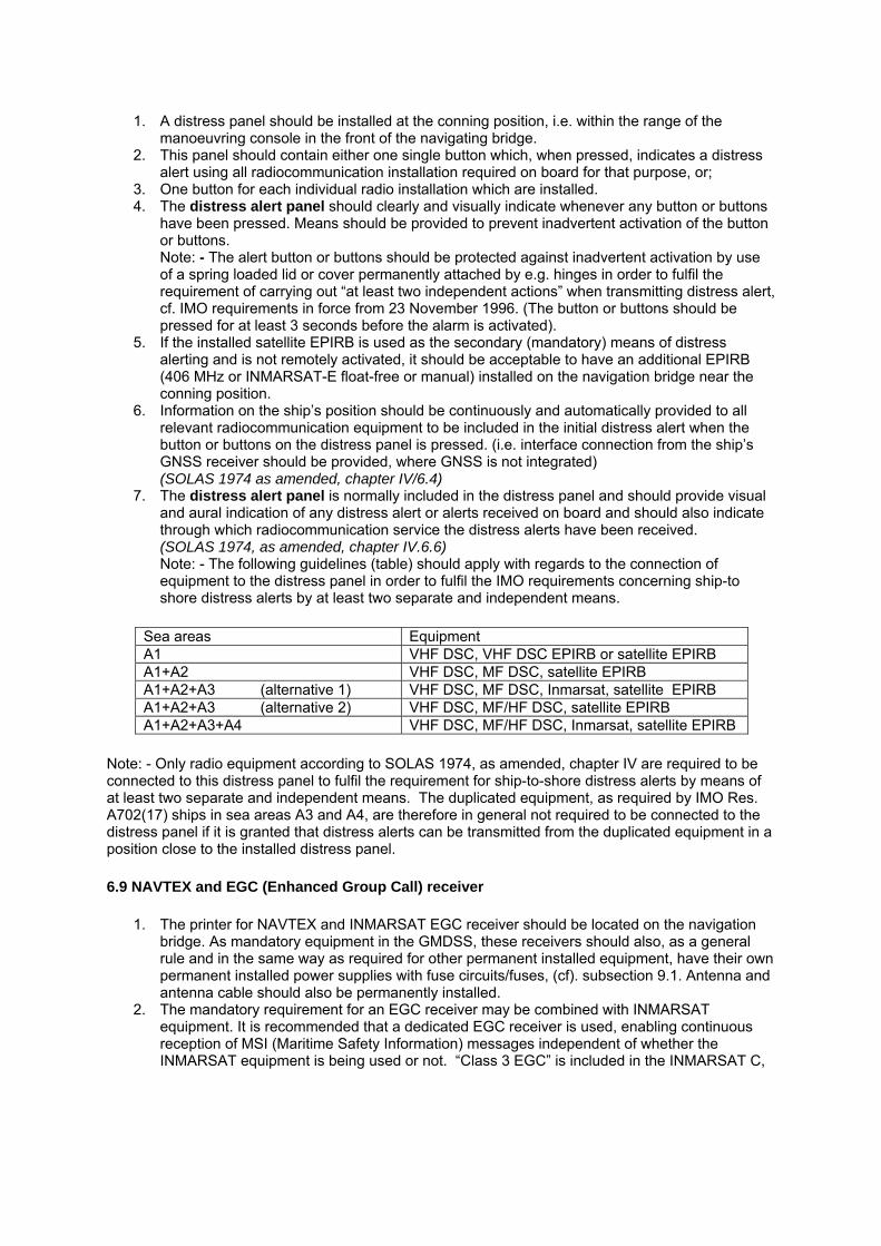
7. The distress alert panel is normally included in the distress panel and should provide visual and aural indication of any distress alert or alerts received on board and should also indicate through which radiocommunication service the distress alerts have been received. (SOLAS 1974, as amended, chapter IV.6.6) Note: - The following guidelines (table) should apply with regards to the connection of equipment to the distress panel in order to fulfil the IMO requirements concerning ship-to shore distress alerts by at least two separate and independent means.
Sea areas Equipment A1 VHF DSC, VHF DSC EPIRB or satellite EPIRB A1+A2 VHF DSC, MF DSC, satellite EPIRB A1+A2+A3 (alternative 1) VHF DSC, MF DSC, Inmarsat, satellite EPIRB A1+A2+A3 (alternative 2) VHF DSC, MF/HF DSC, satellite EPIRB A1+A2+A3+A4 VHF DSC, MF/HF DSC, Inmarsat, satellite EPIRB
Note: - Only radio equipment according to SOLAS 1974, as amended, chapter IV are required to be connected to this distress panel to fulfil the requirement for ship-to-shore distress alerts by means of at least two separate and independent means. The duplicated equipment, as required by IMO Res. A702(17) ships in sea areas A3 and A4, are therefore in general not required to be connected to the distress panel if it is granted that distress alerts can be transmitted from the duplicated equipment in a position close to the installed distress panel.
6.9 NAVTEX and EGC (Enhanced Group Call) receiver
1. The printer for NAVTEX and INMARSAT EGC receiver should be located on the navigation bridge. As mandatory equipment in the GMDSS, these receivers should also, as a general rule and in the same way as required for other permanent installed equipment, have their own permanent installed power supplies with fuse circuits/fuses, (cf). subsection 9.1. Antenna and antenna cable should also be permanently installed.
2. The mandatory requirement for an EGC receiver may be combined with INMARSAT equipment. It is recommended that a dedicated EGC receiver is used, enabling continuous reception of MSI (Maritime Safety Information) messages independent of whether the INMARSAT equipment is being used or not. “Class 3 EGC” is included in the INMARSAT C,
but only shares the antenna with this equipment and functions in parallel with and separate of the INMARSAT C equipment. (SOLAS 1974, as amended, chapters IV.7.1.4 and 7.1.5, and IMO resolutionA.701(17))
6.10 Satellite float-free EPIRB
The satellite float-free EPIRB should be located/installed so that the following requirements are fulfilled:
1. The EPIRB should - with greatest possible probability - float free and avoid being caught in railings, superstructure etc., if the ship sinks.
2. The EPIRB should be located so that it may be easily released manually and brought to the survival craft by one person. It should therefore not be located in a radar mast or any other place which can only be reached by vertical ladder. (SOLAS 1974, as amended, chapters IV.7.1.6, 8.1.5.2, 9.1.3.1, 10.1.4.1, 10.2.3.1 and IMO resolutions A.763(18), A.810(19), and A.812(19)) Note: - A float-free EPIRB may also be used to fulfil the requirements for one piece of equipment (of two), which is capable of transmitting distress alert to shore from or near the navigating bridge of the ship. Under such conditions the float-free EPIRB must fulfil the following additional requirements with regards to location/installation:
3. The EPIRB must be installed in the vicinity of the navigation bridge, i.e. on the wings of the navigation bridge. Access via vertical ladder should not be accepted. A location on the top of the wheelhouse may be accepted to fulfil the requirement if accessible by stairs. (SOLAS 1974, as amended, chapter IV/7 and Com/circ. 105) or
4. It may be possible to activate the EPIRB remotely from the bridge. If remote activation is used, the EPIRB should be installed so that it has unobstructed hemispherical line of sight to the satellites. (COM /Circ. 105) Note: - It should be considered that the main function of the EPIRB is float-free activation. If the additional requirements mentioned above cannot be met without reducing the reliability of the float-free activation, priority must be given to this requirement. Alternatively, two float-free EPIRBs should be installed.
5. The EPIRB should be equipped with a buoyant lanyard suitable for use as a tether to life raft etc. Such buoyant lanyard should be so arranged as to prevent it being trapped in the ship’s structure. (IMO resolution A.810(19))
6. The EPIRB should be marked with the ship’s call sign, serial number of EPIRB, MMSI number (if applicable), 15 Hex ID, and battery expiry date.
6.11 Radar transponders (SART)
1. The radar transponders should be placed in brackets on both sides of the ship and preferably visible from the navigation bridge. It must be easy to bring the transponders to the lifeboats or life-rafts. A visible location inside the navigation bridge, close to the outer doors, is recommended. Alternatively one radar transponder should be placed in bracket in each survival craft (normally covered lifeboats) if such location permits rapidly replacing of the SART’s into any survival crafts which may be used in emergency situations.

The SART should be provided with a pole or other arrangement compatible with the antenna pocket in the survival craft in order to fulfil the required height of at least 1 meter above sea level.
2. On ships carrying at least two radar transponders and equipped with free-fall lifeboats one of the radar transponders should be stowed in a free-fall lifeboat and the other located in the immediate vicinity of the navigation bridge so it can be utilised on board and ready for transfer to any of the other survival craft. (SOLAS 1974, as amended, chapter III.6.2.2 and IMO resolution A.802(19))
3. The SART’s should have waterproof marking with operational instructions, battery expiry date and the ship’s name and call sign.
6.12 Hand held (Two-way) GMDSS VHF transceivers
1. Obligatory hand held VHF transceivers including their emergency batteries (primary batteries normally of Lithium type) should be located in a central and easily accessible position on the navigation bridge. If such equipment is placed in a lockable cabinet, it must be possible to get easy access to the hand held VHF transceivers without the use of tools.
2. Primary batteries must be sealed for use only in emergency situations and marked by the supplier with battery expiry date. The battery will be considered as exhausted and used if its seal is broken, and a new battery will be requested during radio survey, cf. the IMO requirement for 8-hours operation in emergency situations.
3. If hand held VHF with re-chargeable NiCad batteries (secondary batteries) are used for on-board communications, chargers for these batteries should be provided. (SOLAS 1974, as amended, chapter III.6.2.1 and IMO resolutions A.762(18) and A.809(19))
4. Hand held VHF transceivers should have waterproof marking with the ship’s name and call sign. The primary battery must be marked with expire date. Channel numbers must be stated on the equipment.
6.13 Hand held VHF transceivers and communications from the wings of the navigation bridge
Requirements for radiocommunications from the wings of the navigation bridge are laid down in the SOLAS Convention. In order to fulfil this requirement, mandatory hand held GMDSS VHF can be used. (see subsection 6.1). Alternatively a simplex VHF transceiver (single frequency only) or remote controlled units with channel selector, loudspeaker and microphone may be installed in these positions. These remote controlled units must be controlled by a VHF installed in the front of the navigation bridge. (SOLAS 1974 as amended, chapter IV.6.3. and COM/Circ 105 Clarification)
6.14 Aeronautical mobile emergency radiocommunication equipment
1. All passenger ships should be provided with means for two-way on-scene radiocommunications for search and rescue purposes using the aeronautical frequencies 121.5 MHz and 123.1 MHz from the navigation bridge. Such equipment should be marked with the ships name and call sign. The primary battery must be marked with expiry date. (SOLAS 1974 as amended, chapter IV.7.5)
2. Approved equipment may be of a fixed type or a hand held type. The equipment should be provided with the frequencies 121.5 MHz and 123.1 MHz only. This equipment must be provided with a headset and microphone.
6.15 GNSS – navigational satellite system
1. In passenger ships irrespective of size, information on the ship’s position should be continuously and automatically provided to all relevant radiocommunication equipment. With

such connections the ship’s position will be included in the initial distress alerts. (SOLAS 1974, as amended, chapters IV/6.5 and V/19)
2. In cargo ships, where GNSS should be installed in accordance with new chapter V/19, automatic updating of the ship’s position into the DSC equipment and IINMARSAT equipment should be possible. If such automatic updating is not possible, it is required to enter the ship’s position manually into relevant GMDSS equipment at intervals not exceeding 4 hours whenever the ship is under way. (SOLAS 1974, as amended, chapter IV, new regulation 18) If the GNSS is connected to the GMDSS equipment, it should (similar to the mandatory GMDSS equipment) be supplied with energy from the reserve source of energy/batteries. (SOLAS 1974, as amended, chapter IV 13.8)
6.16 Connections of Navigational sensors
6.16.1 GNSS - Receiver
A GNSS receiver must be connected to the relevant radio communication equipment (DSC controller, GMDSS satellite equipment) in order to provide information on the ship’s position continuously and automatically to the radio equipment. This GNSS receiver must (similar to the mandatory GMDSS equipment) also be supplied from the reserve source of energy/batteries.
6.16.2 Heading sensor
If the GMDSS satellite equipment requires automatic antenna adjustment according to ships heading, the heading sensor (GYRO) should be connected.
In this case the GYRO should also be supplied with energy from the reserve source of energy/batteries.
7. Antenna installation
7.1 General
Special attention should be paid to the location and installation of the different antennae on a ship in order to ensure effective and efficient communication. Incorrect installed antennas will degrade the performance of the radio equipment and will reduce the range of radiocommunications.
7.2 Location of VHF antennae
1. VHF antennae should be placed in a position which is as elevated and free as possible, with at least 2 metres horizontal separation from constructions made by conductive materials.
2. VHF antennae should have a vertical polarisation. 3. Ideally there should not be more than one antenna on the same level. 4. The location of mandatory VHF-antennae should be given priority compared with mobile
telephone antennae. If they are located on the same level, the distance between them should be at least 5 meters.
5. It is recommended to use double screened cable with a maximum loss of 3 dB. 6. All outdoor installed connectors on the coaxial cables should be watertight by design in order
to give protection against water penetration into the antenna cable.

7. AIS VHF antenna should be installed safely away from interfering high-power energy sources like radar and other transmitting radio antennae, preferably at least 3 metres away from and out of the transmitting beam.
8. The AIS VHF antenna should be mounted directly above or below the ship's primary VHF radiotelephone antenna, with no horizontal separation and with minimum 2 m vertical separation. If it is located on the same level as other antennae, the distance apart should be at least 5 metres.
7.3 Location and choice of MF/HF antennae
1. The mounting arrangement of the antenna or pedestal must be constructed in order to withstand the strain from swaying and vibration. The transmitting whip antenna should be installed as vertical as possible.
2. Wire-antennae should be protected against breakage by having a weak link installed. 3. Whip antennae should be installed as vertical as possible and located in an elevated position
on the ship at least 1 metre away from conductive structures. 4. Attention must be paid to self-supportive vertical antennae and their swaying radius. 5. The recommended minimum length of the antenna is 8 metres. 6. The down lead from the base of the antenna to the antenna tuner should be insulated and run
as vertically as possible and not less than 45 degrees towards the horizontal plane. 7. The transmitting antenna should have an insulation resistance to earth which is
recommended to be of more than 50 MΩ in dry weather and of no less than 5MΩ in humid weather (transmitter to be disconnected when measuring).
7.4 Location of antenna tuner for MF/HF transceiver
The antenna tuner should normally be located externally (outdoor) and as close to the antenna as possible, and so that the down lead wire/cable from the antenna should be as vertical as possible.
7.5 Receiving antennas
1. As a general rule, all receivers including watch-keeping receivers should have their own separate antenna.
2. Antennae for watch-keeping receivers should be located as far away as possible from MF/HF transmitting antennae in order to minimise receiver blocking.
7.6 Satellite communication antennae
7.6.1 General
1. In general, satellite antennae must be located so that they have a 360 degree free view for the satellite at all times. In practical terms this can be difficult to achieve due to shadow sectors from nearby structures.
2. It is recommended for INMARSAT-A., B and F-77 antennae (stabilised directional antennae) that communication should be maintained with the satellite down to an elevation of minus 5 degrees. For INMARSAT-C (omni-directional antenna) it is recommended that communication should be maintained with the satellite down to an elevation of minus 5 degrees in the fore and aft direction and minus 15 degrees in the port and starboard direction.
7.6.2 Satellite communication antenna installation
The following guidelines should be observed in order to fulfil the above recommendations:
1. The antenna should be located at the top of the radar mast; or

2. On a pedestal, in the radar mast, or on the top deck so that: -for directive antennae; shadows from constructions, especially within a distance of 10 metres, is maximum 6 degrees; -for omnidirectional antennae; shadows from constructions, especially within a distance of 1 metre, is maximum 2 degrees.
3. Antennae must be installed in a readily accessible location.
4. They should not be located in an area where they can be damaged by heat and smoke.
5. The satellite antenna must not be located on the same plane as the ships radar antenna.
6. GNSS antennae should not be located close to or on the same plane as the INMARSAT antenna.
7. Consideration should be given to installing the INMARSAT antenna on a suitable pedestal. (Ref. IMO resolutions A.698(17), A-663(16), A 807(19) and INMARSAT Design and Installation Guidelines) Note: - The mast/or pedestal must be constructed so that vibrations are reduced as much as possible.
7.6.3 Safe antenna distances
The following “safe distance” from INMARSAT antennae to other antennae and to the compass are recommended:
1. Distance to the HF antenna should be more than 5 metres.
2. Distance to VHF antennae should be more than 4 metres.
3. Distance to the magnetic compass should be more than 3 metres. (Cf. the installation manual for the equipment and INMARSAT guidelines)
7.6.4 INMARSAT-C antenna
The antenna should be constructed so as to function up to 15 degrees pitch and roll. In order to obtain this result, the antenna should be located in such position that no objects or constructions down to 15 degrees below the horizon are degrading the performance of the equipment.
Note: - As it may be difficult to fulfil this recommendation fore-and-aft, the free area in this direction may be reduced to 5 below the horizon. (IMO resolutions A663(16) and A.807(19))
Zenith
Horizon 15°

7.6.5 Calculation of distance to obstructions:
If obstructions such as i.e. mast, funnel etc. is unavoidable, the following guidelines should apply:
The distance to the obstruction should be so that the obstruction only covers a 2 degrees sector.
Note: - In such case the safe distance will be the following: 20 x the diameter of the obstruction (in metres).
diameter (m) max. angle 2 degrees
If two INMARSAT C antennae are installed the vertical distance between them should be at least 1 meter to eliminate interference.
7.6.6 Antenna cable
The manufacturers specifications regarding total attenuation and maximum DC resistance (short-circuit in one end) must be complied with. Only double-screened cable should be used.
7.6.7 Antennae for voluntary radio equipment
Antennae for voluntary radio equipment may be located on deck, provided its use does not interfere with antennae of mandatory radio equipment. When mobile telephone is installed on board ships, special attention should be made to the facts that some types of mobile telephones (especially GSM telephone equipment) may interfere with the ship's navigational equipment (especially GNSS) and other electronic equipment.
7.7 Installation of coaxial cables
Coaxial cables should be installed in separate ducting and at least 10 cm away from power supply cables. Incorrect installation of cables may change their characteristic impedance resulting in power reflections, which will attenuate the RF signal and reduce the efficiency of the radio equipment.
In VHF antennae the reflected power should not be greater than 10% of the measured output power.
The following guidelines should be applied when bending coaxial cables:
1. Cables should be crossed at right angles.
2. Where there is one bend in a permanent fixture the bending radius should be 5 times the cable’s outside diameter.
3. Where there are several bends, the bending radius should be 10 times the outside diameter of the cable.

4. When using flexible cable the bending radius should be 20 times the outside diameter of the cable.
8. EMC, earthing and screening
8.1 Electromagnetic Compatibility (EMC)
8.1.1 General
All reasonable and practical steps should be taken to ensure EMC compatibility between the equipment concerned and other radio communication and navigational equipment carried on board in compliance with the relevant requirements of chapter IV and V of the SOLAS Convention as amended. In order to avoid interference the following rules apply:
1. Radio installations must not cause harmful interference to other electronic, electrical or navigational systems on board ships.
2. However, these other systems must not cause harmful interference to the radio installation.
3. In order to avoid electromagnetic noise interference it is essential that manufacturers’ guidelines relating to EMC, screening and earthing are correctly followed. (SOLAS 1974, as amended, IV/6.2.1 and chapter V/17 and IMO resolutions A694(17) and A.813(19))
8.1.2 Voluntary radio equipment
Additional, voluntarily carried Non-GMDSS radio equipment like e.g.
-Mobile telephone -Radio amateur stations -Satellite stations
Operation of such equipment is at the discretion of the master. It may be installed on the bridge provided that the EMC requirements are fulfilled and navigation and radio communication is not degraded.
8.2 Screening of cables
In order to avoid interference the following guidelines should apply with regards to screening of cables:
1. Coaxial down leads must be used for all receiving antennae and the coax screen should be connected to ground on at least one end.
2. All cables within a distance of 2 metres from a transmitting antenna must be screened and the screen properly earthed in a metal tube or duct.
8.3 Earthing
Earthing of radio equipment should be carried out in accordance with appropriate guidelines for Earthing in Maritime Installations required in international standards. Great care should be taken in order to fulfil the following rules:
1. Each unit of radio equipment must have a separated earth connection.
2. MF/HF antenna tuners must be earthed with either a copper bar or copper band.
3. The earthing bar or strap must be as short as possible, should not be more than one metre in length, and should be at least 60 mm in width.
4. For earthing straps up to 5 metres in length the width should be at least 100 mm (May be relevant on board vessels made of wood or synthetic materials).
5. It should be noted that a long earthing strap or bar will act as an antenna and radiate energy.
6. Copper bars and straps should be brazed to the steel bulkhead in order to eliminate corrosion and vibration and make a good earth connection.
7. Great care should be taken when earthing radio equipment on ships with aluminium superstructures in order to avoid galvanic corrosion. An approved and acceptable method of earthing should be used on such vessels. Note: - Insufficient earthing of the power amplifier may lead to capacitive and inductive connections between power cables etc. and cause interference to fire alarms, navigational equipment, inter-com. and other equipment. The transmitter output power may also be reduced.
9. Sources of energy
9.1 Main source of electrical power
The main source of electrical power is defined as the ship’s mains. All the basic and duplicated equipment must have an independent power supply from the ships mains. The battery charging arrangement used to charge any batteries associated with the reserve source of energy must also have an independent supply from the ships mains.
It is not advisable to provide the main source of electrical power to the GMDSS communications equipment through the battery charger. If a fault occurs in the battery charger, which renders it defective, it may not be possible to operate the equipment from the ship’s mains. Batteries used in the reserve source of energy will become discharged eventually leading to loss of all power supplies. (SOLAS 1974, as amended, chapter II and IMO resolution A.702(17) Annex item. 2.3)
9.2 Emergency source of electrical power
The emergency source of electrical power is defined as the emergency supply and is usually taken from the ship’s emergency generator. SOLAS requirements for the emergency source do not apply to cargo ships of less than 500 gross tonnage (gt). All other SOLAS ships constructed on or after 1 July 1986 are required to have an emergency source of electrical power. It should be observed that the GMDSS requirements concerning the emergency source have been made compulsory only for ships constructed later than 1 February 1995.

The emergency source must be adequate to operate both the basic and duplicated equipment (if applicable)for the duration as specified in SOLAS chapter II, i.e. 18 hours on cargo ship and for 36 hours on passenger ship. (SOLAS 1974, as emended, chapters II-1/42 and 43)
9.3 Reserve source of energy
1. The radio reserve source or sources of energy should meet the requirements set out in regulation IV/13 of SOLAS 1974, as amended, and in IMO resolutions A.694(17) and A.702(17), as applicable. It usually consists of rechargeable batteries and is used to supply the communication equipment in the event of failure of the ship’s mains and emergency source of electrical power. All passenger ships irrespective of size and cargo ships of 300 gt. and upwards should have a reserve source or sources of energy for the operation of the basic equipment, and the duplicated equipment if such equipment is required.
2. The changeover from the ship’s mains or emergency supply to the reserve source of energy should be done automatically and in such a manner that both the basic and duplicated communications equipment will be connected simultaneously. Where the changeover is done manually, the switch should be readily accessible to the radio operator, clearly labelled and located on the navigation bridge. Such changeover should not result in the loss of data stored in memories.
3. One bank of batteries may be acceptable if the capacity is sufficient to operate both the basic and duplicated radio equipment simultaneously. The battery capacity should also be sufficient to operate the gyro (if applicable), GNSS, and emergency light.
4. Any fault in the radio batteries or the battery charger should not affect both the basic and duplicated radio equipment and should not prevent the operation of the radio equipment from the ships mains or emergency supply.
5. The reserve source of energy must be capable of operating the radio installation for at least: 11 hours on ships provided with an emergency supply which is adequate to operate the radiocommunications equipment for a period of 18 hours on cargo ships and 36 hours on passenger ships; or 26 hours on ships not provided with an emergency supply as outlined in (9.2) above. (SOLAS 1994, as amended, chapters IV 13.2, 13.4, 13.5, 13.8 and IMO resolutions A.694(17), A.702(17) – Annex item 2.3, COMSAR/Circ.. 16)
9.4 Radio battery capacity
When defining the minimum required battery capacity, consideration should be given to the expected extreme temperatures for the location of the battery and reduction of its capacity during its lifetime in addition to the loads which are to be connected to it.
1. The batteries must have enough capacity to operate all the GMDSS radio equipment for the specific times outlined in 9.3.5 above. The total load for the entire radio installation should be calculated prior to the installation of any radio batteries for the reserve supply.
2. Where the basic and duplicated radio equipment cannot be operated simultaneously, the battery capacity should be sufficient to operate the equipment with the highest power consumption.
3. Where the basic and duplicated radio equipment are connected simultaneously the battery capacity should be sufficient to meet the average consumption of all connected equipment including any additional loads such as printers, VDU’s etc.
4. If the capacity requirement of radio batteries is to be maintained over their normal life cycle, an extra 40% capacity should be added to the minimum calculated capacity.
5. When calculating discharge time the following guidelines may be of assistance: .1 The capacity of a lead acid battery is normally quoted at 20 hours of discharge at an
operational temperature of 20 degrees C. .2 The capacity at 1 hour discharge is approximately 50% of the capacity at 20 hours discharge. .3 The capacity at 6 hours discharge is approximately 80% of the capacity at 20 hours discharge. .4 For batteries other than the lead acid type the capacity at 1 hour discharge is approximately 60% of the capacity at 10 hours discharge and 6 hours discharge will be approximately 92% of the capacity at 10 hours discharge.
6. The capacity of the radio batteries should be checked at intervals not exceeding 12 months when the ship is not at sea. One method of checking the capacity is to fully discharge and recharge the batteries using normal operation current over a period of 10 hours. Assessment of the charge condition can be made at any time, but it should be done without significant discharge of the battery when the ship is at sea. Another method could be to check the capacity by means of a battery tester, e.g. in connection with a radio survey. (SOLAS 1974, as amended, chapter IV/13 and IMO resolution A.702(17), COMSAR/Circ. 16) Note: - When determining the battery capacity the following must also be taken into consideration: -The battery is normally not fully charged. -Reduction of capacity due to ageing. -Reduction of capacity due to high or low temperatures. -Reduction of capacity due to rapid discharge.
9.5 Radio batteries
The batteries should be properly marked with type or construction, rated capacity, and installation date. The marking must be visible when the batteries have been installed and during their lifetime. A label warning of explosion danger should be displayed near the installed batteries.
1. Any type or construction of batteries (e.g. lead acid, alkaline, maintenance free, traction, semi-traction, etc.) may be used as reserve source or sources of energy, taking into consideration the environmental conditions of the location where they are installed.
2. The battery should maintain its rated capacity when inclined at any angle up to 22½ degrees in any orientation.
3. All battery units must be securely braced so that they will not be dislocated by movement of the ship.
4. An instruction manual which contains all necessary specifications of the batteries should be available on board. The information should include at least: .1 capacity and temperature range within which the stated capacity is maintained for the specific operation period i.e. 1 hour or 6 hours; .2 charging voltage and current limits in order to keep batteries fully charged while preventing overcharging; .3 actual specific gravity of the electrolyte and/or cell voltages or the voltage of the fully charged battery; .4 guidelines on how to carry out a controlled discharge test; .5 methods of determining the condition of charge of the battery, e.g. check of specific gravity of electrolyte (acid density) or check of battery cell voltage/battery voltages by using an

accurate measuring instrument in according with the battery manufacturer’s specifications; .6 requirement for ventilation; and .7 requirement for maintenance.
5. Equipment requiring a lower voltage than the total voltage of the battery bank should not be connected to a part of the battery bank.
6. The batteries should be installed in the upper part of the ship, in an elevated position and as close to the radio equipment as possible.
7. An outdoor located battery case should be avoided due to considerable temperature variation. Note: - Ideal location for the radio batteries is in a battery room with a constant temperature of approx. 20 degrees C. The location should in general satisfy the manufacturers’ specifications with regards to temperature tolerance and environmental strain in accordance with IEC 60945 or other equivalent standards.
8. Batteries of different types, different cell constructions, different capacities or different manufacturers should not be mixed in a battery bank.
9. Batteries of different types and different cell construction should not be installed in the same location if they can affect each other.
10. Sufficient ventilation for batteries should be provided, as required by the battery manufacturer. 11. Electrical installations including battery chargers, located in the battery room should be
intrinsically safe. 12. Sufficient space between batteries or battery banks should be provided in order to enable
inspections and maintenance. 13. The cabling from the batteries should be protected against earth- and short-circuits and be
appropriately fused and installed according to recognised international standards (IEC 60092-101 and IEC 60533). Battery cables should have sufficient dimensions to prevent voltage reduction at peak current consumption. (SOLAS 1974, as amended, chapter V/13 and COMSAR/Circ. 16)
9.6 Uninterruptible power supplies (UPS)
A UPS is defined as a device which for a specific period of time supplies continuous power to radio equipment independent of any power failures in the ship’s main or emergency source of electric energy. The UPS, installed as the reserve source or sources of energy, should meet the general requirements set out in regulation IV/13 of the SOLAS 1974, as amended, and in resolution A.694(17), as applicable, and should also comply with the following requirements:
1. Comprise an automatic charger, complying with requirements set out in SOLAS/IV chapter 13; and
2. Comprise rechargeable accumulator batteries, complying with the guidelines regarding accumulator batteries.
3. Provisions should be made for an aural alarm and visual indication at the position from which the ship is normally navigated, indicating any failure in the UPS which is not monitored by the alarm and indicators required by the guidelines regarding automatic chargers.
4. The UPS should be operational within 5 seconds of switching on.
5. The UPS should be so designed and constructed that it is protected against damage resulting from disconnecting the batteries or, with the battery disconnected, short-circuiting the UPS battery connections. If this protection is provided by electronic means it should automatically reset following removal of the open or short-circuit conditions. (COMSAR/Circ. 16) Note: - If the UPS does not fulfil the requirements in accordance with SOLAS chapter IV/13

and IMO resolution A.702(17), two separate UPS systems should be installed; one for the basic radio equipment and one for the duplicated equipment. The capacity of batteries used in UPS systems is normally stated at a discharge time of 10 hours. When discharging such batteries at shorter time, i.e. 1 hour in accordance with the GMDSS requirements, it will only be possible to utilise approx. 60% of the battery capacity. It is therefore recommended to dimension such batteries to be one and a half times larger than the total load.
9.7 Automatic battery chargers
Automatic chargers for radio batteries should meet the general requirements set out in regulation IV/13 of SOLAS 1974, as amended and IMO resolution A.694(17) and should also comply with the following requirements:
1. The charger must be capable of recharging the completely discharged accumulator batteries to the minimum required capacity within 10 hours.
2. The charger should be capable of keeping the batteries appropriate charged as prescribed by the manufacturer for permanent charging.
3. The supplied voltage and current should always be within the tolerance limits prescribed by the battery manufacturer, taking into account the environmental temperature of the battery, likely to be experienced in ship. A protection should be provided against over charging or discharging of batteries from a possible fault in the charger.
4. The automatic charger should be provided with a visual indication that it is switched on. An indication of the battery voltage and charge/discharge current should be available on the navigation bridge.
5. Provisions should be made for an aural alarm and visual indication at the position from which the ship is normally navigated, indicating when the charging voltage or current is outside the limits given by the manufacturer and indicating failure of the mains supply and/or charger. It should not be possible to disable this alarm and indication and it should only be possible to acknowledge and silence the alarm manually. Both the alarm condition and indication should reset automatically when normal charging condition has been restored. Failure of the alarm system should not interrupt the charging or discharging of batteries.
6. The automatic charger should be operational within five seconds of switching on or after a power supply interruption.
7. The automatic charger should be so designed and constructed that it is protected against damage resulting from disconnection the batteries or, with the battery disconnected, short-circuiting the battery connection. If this protection is provided by electronic means it should automatically reset following removal of the open or short-circuit conditions. (SOLAS 1974, as amended, chapter IV.13.6.1, COMSAR/Circ. 16) Note: - As said in item 9.1 above it is not advisable to provide the main source of energy to the GMDSS equipment through the battery charger. However, if the battery charger is used to supply parts of the GMDSS installation directly, i.e. the MF/HF transceiver, the capacity of the charger should be dimensioned for simultaneous supply of connected equipment and maintaining a sufficient charging of the batteries in accordance with SOLAS 1974, as amended, chapter IV/13.2.
9.8 Protection of circuits for accumulator batteries
1. Battery circuits (i.e. the cables from battery case/room) should be protected against short-circuit and overload. The protection device is to be installed as near as possible to the batteries.

2. When conductors from the batteries are not protected against short-circuit and overload, they are to be installed so as to be proof against short circuit and earth faults. The requirements for short-circuit protection also apply to charge current circuits.
Note: - For certain applications it may be necessary to establish measures which may conflict with these requirements. As an example, screening of battery cables can be required to avoid electro-magnetic interference, e.g. by using single-core insulated cables without screening installed in separate metal pipes which are properly earthed. Special measures should then be established to reduce the possibility of mechanical damage to the cables.
Equivalent solutions may be accepted, e.g. by using double-screened cables in the battery room with explosion-proof fuses. The inner screen must be treated according to Ex-rules, but the outer screen can be treated according to what is necessary to achieve good EMC-screening. The outer screen can e.g. be earthed at both ends to protect against High Frequency EMC-fields.
10. Cabling and wiring
10.1 Battery circuits – fuses and breakers
1. Each radio system should have separate fuses for both AC and DC voltages to which it is connected. AC and DC fuse boards should be located on the bridge or in close proximity to the bridge.
2. A single fault in one of the power units must not affect both the basic and duplicated radio equipment.
3. All fuses and breakers must be clearly marked and labelled to clearly indicate which equipment is being protected.
Note: - A VHF with DSC, a MF/HF DSC transceiver, a NBDP with printer, and INMARSAT equipment with a VDU and printer are each considered as a “radio system”.
11 Installation of GMDSS radio equipment on board mobile offshore drilling units (MODU)
Mobile offshore drilling units should fulfil the GMDSS requirements laid down in IMO’s MODU Code, as revised in 1991. This revision introduced provisions based on the GMDSS requirements. All GMDSS requirements should as a general rule be fulfilled. However, for drilling units the requirement for duplication may be considered as fulfilled if the radio installation complies with regulation 11.5.2 of the MODU Code as follows:
1. Each unit while stationary at the site, including when engaged in drilling operations, should comply with all requirements prescribed in chapter IV of the SOLAS amendments that are applicable to ship sailing through the same area.
2. Taking into account the different types of accident which may occur on the MODU, additional radio equipment should be installed in a room or position, which could be the bridge or an emergency control room, situated as far as practical from the radio equipment fitted in compliance with section 11.5.1, so that a single accident in any part of the MODU could

deprive the MODU of all facilities for radiocommunications.
3. The additional radio equipment should comply with the following regulations of the 1988 SOLAS amendment for MODUs drilling in: .1 sea area A1, the equipment prescribed in regulation IV/7.1.1; .2 sea area A2, the equipment prescribed by regulations IV/7,1,1 and IV/9.1.1; and .3 sea area A3, the equipment prescribed by regulations IV/7.1.1 and IV/10.1.1, plus 10.2; or alternatively, as required by regulations IV/7.1.1 and 10.2.1; .4 sea area A4, the equipment prescribed by regulations IV/7.1.1 and IV/10.2.1.
4. If the acoustic noise level in a room fitted with operating controls for radio equipment is so high or could be so high, during particular operating conditions, that it may disturb or prevent proper use of the radio equipment, adequate noise protection should be provided by mechanical or other means, in association with the operating controls for the radio equipment.
Note: - All requirements for chapter IV of the 1988 SOLAS amendments referring to “from the position the ship is normally navigated” should be applied as meaning “from a position (or from the positions), which is continuously manned and which is controlling the MODU. Watch-keeping on DSC and other emergency and calling channels should be kept from a position which is continuously manned. Watch-keeping and the operation of all radio equipment which are required on board should be carried out by a person holding a GOC/GMDSS or ROC/GMDSS (if only A1 installation) radio operator certificate.
**WARNING**
The antennae of operational radio transmitters can pose a serious health risk. If working in the vicinity of any transmitter antenna, adequate precautions should be taken to prevent activation of any equipment noting that an automatic over-ride of the antenna earthing arrangements may well be provided on the ship.
CAUTION:
Lead acid and alkaline batteries should not be installed in the same compartment, unless the lead acid battery is the sealed type.
Exceptionally, to enable the vessel to sail when correct batteries are not available, a mix is permissible. When this exception is exercised, confirm that clear warnings are posted highlighting the need to use separate hydrometers for each type of battery.
WARNING
Use of MF/HF transmitting equipment is prohibited in some locations and when handling some types of cargo. Before any transmitter is used it is essential that confirmation is obtained that it is safe and permitted to do so under the prevailing conditions at the time.
WARNING
Before any MF/HF transmitter is used it should first be established that the antennae are in place and that no hazard is presented to personnel who may be working in the vicinity of the antennae.

WARNING
Use of MF/HF transmitting equipment is prohibited in some locations and when handling some types of cargo. Before any transmitter is used it is essential that confirmation is obtained that it is safe, and permitted, to do so under the prevailing conditions at the time.
WARNING
Before any MF/HF transmitter is used it should first be established that the antennae are in place and that no hazard is presented to personnel who may be working in the antennae.
HEAD OFFICE
Selex Communications Ltd Marine Radio Surveys & Inspections Marconi House New Street Chelmsford Essex CM1 1PL
Telephone 01245 275888 Facsimile 01245 275500
Email: [email protected]
LONDON OFFICE
Selex Communications Ltd Units 5F Standard Industrial Estate 2 Henley Road Silvertown London E16 2ES
Telephone 0207 511 4391 Facsimile 0207 511 4483
SOUTHAMPTON OFFICE
Selex Communications Ltd Unit 409 Solent Business Centre Millbrook Road West Southampton Hants SO15 0HW
Telephone 02380 511868 Facsimile 02380 511890
FALMOUTH OFFICE

Selex Communications Ltd Unit 7, Waterside House Falmouth Road Penryn TR10 8BD
Telephone 01326 378031 Facsimile 01326 379442
BRISTOL
Selex Communications Ltd Broadquay House Orpen Park Ahs Ridge Road Almondsbury Bristol BS32 4QD
Telephone: 01454 618585 Fascimile: 01454 617310
KILKEEL (N Ireland)
Selex Communications Ltd 28b The Harbour Kilkeel Co. Down BT34 4AX
Telephone 02841 769009 Facsimile 02841 769430
ABERDEEN OFFICE
Selex Communications Ltd 28 Riverside Drive Aberdeen AB11 7DB
Telephone 01224 585334 Facsimile 01224 575975
FRASERBURGH OFFICE
Selex Communications Ltd 7 Balaclava Fraserburgh AB43 9EB
Telephone 01346 518187 Facsimile 01346 515282
NEWCASTLE OFFICE
Selex Communications Ltd Unit 26 Byker Business Develop. Centre Albion Row, Byker Newcastle-upon-Tyne NE6 1LQ
Telephone 0191 265 0374 Facsimile 0191 265 0382
LIVERPOOL OFFICE
Selex Communications Ltd 89 Woodside Park Birkenhead Merseyside CH41 1EL
Telephone 0151 647 6222 Facsimile 0151 647 3374
HULL OFFICE
Selex Communications Ltd Unit E4 Chamberlain Business Centre, Chamberlain Road, Kingston upon Hull, HU8 8HL
Telephone 01482 326144 Facsimile 01482 216472
LOWESTOFT OFFICE
Selex Communications Ltd 9 Battery Green Road Lowestoft Suffolk NR32 1DE
Telephone 01502 572365 Facsimile 01502 508955
LOOE
Selex Communications Ltd The Old Harbour Office Buller Quay East Looe Cornwall PL13 1AR
Telephone 01503 265548 Facsimile 01503 265548

GREENOCK
Selex Communications Ltd Unit 9 20 Pottery Street Greenock PA15 2UH
Telephone 01475 744977 Facsimile 01475 744325
ROSYTH
Selex Communications Ltd Room 32, c/o Forth Ports Ports of Rosyth Exmouth Building Rosyth KY11 2XP
Telephone 01383 419606 Facsimile 01383 419461
Further Information Further information on the contents of this Notice can be obtained from: Navigation Safety Branch Bay 2/29 Maritime and Coastguard Agency Spring Place 105 Commercial Road Southampton SO15 1EG Telephone: +44 (0) 23 8032 9146 Fax: +44 (0) 23 8032 9204 E-Mail: [email protected] General Enquiries: 24 Hour Infoline [email protected] 0870 600 6505 MCA Website Address: Internet: http://www.mcga.gov.uk File Ref: MNA 136/002/0056 Published: 12/2005 © Crown Copyright 2005
Safer Lives, Safer Ships, Cleaner Seas