RADIO-FREQUENCY QUADRUPOLE (RFQ) Tender Document … · IPR/TN/PUR/TPT/ET/18-19/2 Dated 03/05/2018...
39
IPR/TN/PUR/TPT/ET/18-19/2 Dated 03/05/2018 SECTION-C 1 RADIO-FREQUENCY QUADRUPOLE (RFQ) Tender Document For FABRICATION, INSPECTION, TESTING, SUPPLY, INSTALLATION & COMMISSIONING OF “RADIO-FREQUENCY QUADRUPOLE (RFQ)” Installation & Commissioning Site Institute for Plasma Research, Gandhinagar
Transcript of RADIO-FREQUENCY QUADRUPOLE (RFQ) Tender Document … · IPR/TN/PUR/TPT/ET/18-19/2 Dated 03/05/2018...

IPR/TN/PUR/TPT/ET/18-19/2 Dated 03/05/2018
SECTION-C
1
RADIO-FREQUENCY QUADRUPOLE (RFQ)
Tender Document
For
FABRICATION, INSPECTION, TESTING, SUPPLY, INSTALLATION &
COMMISSIONING
OF
“RADIO-FREQUENCY QUADRUPOLE (RFQ)”
Installation & Commissioning Site
Institute for Plasma Research, Gandhinagar

IPR/TN/PUR/TPT/ET/18-19/2 Dated 03/05/2018
SECTION-C
2
PART-A (I)
Technical Terms, Conditions & Instruction to Bidders 1.1 Requirement of Radio-Frequency Quadrupole (RFQ)……………………………………………………………………………………………..3
1.2 The parameters of RFQ ................................................................................................................................................. 4
2. SCOPE OF WORK .............................................................................................................................................................. 6
2.1 ENGINEERING SCOPE OF WORK OF COMPONENTS ...................................................................................................... 8
2.1.1 BASE PLATE: ............................................................................................................................................................ 8
2.1.2 VANES: .................................................................................................................................................................... 9
2.1.3 STEMS: .................................................................................................................................................................. 10
2.1.4 VACUUM VESSEL ASSEMBLY: (REF DRG.NO:IPR/17/A3/RFQ/-19030002) ........................................................... 11
2.2. RFQ PROTOTYPE ASSEMBLY: ...................................................................................................................................... 12
2.3 Final Assembly of RFQ components and Vacuum Vessel: ........................................................................................... 13
3 PRELIMINARY DESIGN FOR RFQ & VACUUM VESSEL (External Pressure Vessel) ........................................................... 14
3.1. LIMITS OF DESIGN:...................................................................................................................................................... 14
3.1.1 Vacuum Vessel: ..................................................................................................................................................... 14
3.1.2 RFQ Assembly: ...................................................................................................................................................... 18
4 Acceptance criteria: ........................................................................................................................................................ 21
5. MATERIAL PROCUREMENT ............................................................................................................................................ 26
5.1 MATERIAL SPECIFICATION ........................................................................................................................................... 27
6. CLEANINESS, STORAGE AND WORKMANSHIP ............................................................................................................... 28
7. HANDLING, PACKAGING and TESTING........................................................................................................................... 28
8. DRAWINGS ..................................................................................................................................................................... 29
8.1. Engineering Drawings: ................................................................................................................................................ 29
8.2. Manufacturing Drawing: ............................................................................................................................................. 29
9. DELIVERY ........................................................................................................................................................................ 30
10. INFORMATION REQUIRED WITH BID PROPOSAL......................................................................................................... 30
Annexure-A: Free Issue Material ................................................................................................................................... 31
ANNEXURE-B: Mandatory Conditions ............................................................................................................................... 32
ANNEXURE-C: Technical Bid Format .................................................................................................................................. 33
ANNEXURE –D: List of Drawings ........................................................................................................................................ 37

IPR/TN/PUR/TPT/ET/18-19/2 Dated 03/05/2018
SECTION-C
3
INTRODUCTION
1.1 Requirement of Radio-Frequency Quadrupole (RFQ)
The RFQ Accelerator is being developed under the project “Development of RFQ for
Accelerators” for Ion Irradiation Facility. In Irradiation Facility, an ECR ion source is used to
produce ion beam which is further accelerated by Radio Frequency Accelerator to few MeV
energies. These high energy ions can be used to study the material properties of first wall
components like tungsten, copper, ferrous etc. of a fusion reactor.
In RFQ, basic structure is 4 electrodes, which generate RF electric field in its channel to
accelerate and focus ion beams simultaneously. The RF field also plays the role of transverse
matching and longitudinal bunching functions according to dynamics design. RFQ ingeniously
integrates the above four basic functions in a compact RF cavity. The practical range of operation
of RFQs goes to low velocities as compared to conventional linac. The RFQs bunch the beam
adiabatically, which increases the capture efficiency and transmission. Because of these
remarkable properties, the RFQs are well suited as a first unit of all high current RF linear
accelerators in many advanced applications.
4 electrodes of RFQ are housed in vacuum vessel. For our design, this vacuum vessel will be
made up of Aluminum 6061-T6 Grade to achieve a base pressure ~ 10-8
Torr. The vacuum vessel
will have different ports for RF feed, vacuum components and diagnostics etc. Figure 1(a) and
1(b) give two detailed views of vacuum vessel.
Figure 1(a) : Conceptual Assembly View of RFQ with Vacuum Vessel.

IPR/TN/PUR/TPT/ET/18-19/2 Dated 03/05/2018
SECTION-C
4
Figure 1(b) : Another View of RFQ with Vacuum Vessel.
1.2 The parameters of RFQ
1 MeV RFQ was designed @60 MHz to accept a 50 KeV, 5 mA DC proton beams from the ion
source with a length of ≈ 4.2 m. The resonant frequency of RFQ is sensitive to the vane tip
displacement within order of 2.5 MHz/mm. A photograph of a typical RFQ is shown below in
Figure 2 and Figure 3.
Fig.2: Schematic of RFQ cross section and modulations Fig.3: Typical cross section of a Rod Type RFQ
The RFQ consists of four „vanes‟ that are positioned in such a way that the ion beam passes
through the central region between the tips of the vanes, as shown in the figure 4. In this region
alone the ion beam will see an accelerating field that will accelerate it to the desired energy and
hence this region is most important part of the RFQ fabrication and needs very tight accuracies
during the fabrication process.

IPR/TN/PUR/TPT/ET/18-19/2 Dated 03/05/2018
SECTION-C
5
Fig.4: Bunching and acceleration of the beam between the pole tips
Table 1 below summarizes the parameters and accuracy requirements of RFQ.
Table 1: Parameters of RFQ
Physical
Beam line height from the floor 1.5 m
Overall width ≤1.3 m
Overall length (flange-to-flange) 4.5m
(approximately)
Overall height (from floor) ≤ 2.00 m
Beam
Particle Type Proton
Input beam parameters Match to LEBT at
5 mA
Nominal Input energy (kinetic) 50 (+/- 0.5%) keV
Nominal output energy (kinetic) 1 (+/- 0.15) MeV
Physical beam aperture, 2*R0, beginning-to-end 30 mm (Approx.)
Nominal Beam Current 5 mA
Transmission efficiency >97%
Transverse emittance (normalized, rms) < 0.2 mm mrad
Alignment/
machining
precision
Vane Machining Accuracy 20-50µm
RFQ Vane Alignment Accuracy Better than ±50 µm
Inter-segment Alignment Accuracy Better than ±50 µm
Max transverse position error (X,Y)at upstream and
downstream beam flange
Better than ±100 µm
Max longitudinal position error (Z) Better than ±100 µm
RF
Frequency 60 MHz
Duty factor (CW) 1%
Total RF power for resistive losses and beam
loading
<100 kW
RFQ operating temperature Less than 30 0C
Vacuum Operating pressure ≤4 x 10⁻⁷
torr

IPR/TN/PUR/TPT/ET/18-19/2 Dated 03/05/2018
SECTION-C
6
2. SCOPE OF WORK
Scope of work contains preparation of manufacturing/fabrication drawings, manufacturing and
quality documents (such as Manufacturing and Inspection Plan (MIP), Quality Plan (QP),
manufacturing procedures, welding procedures etc.), inspection, assembly, testing procedures (at
vendor site and at IPR site) and commissioning.
As per the topology of RFQ, the assembly tolerances are very tight – of the order of 100
microns, so proper machining of vanes and stems should be carried out strictly as per drawings.
It is very critical as these vanes and stems are joined by bolting and dowelling only. In order to
ensure that the tight tolerances mentioned above are actually achieved, at each stage precision
metrology using a Coordinate Measurement Machine (CMM) is essential.
The vanes have to be machined to tight tolerances, of the order of few 10s of microns. Since
vanes are exposed to high electric fields, the surface finish of the vanes has to be better than 0.4
m Ra and 2 m Rt.
Also, as the RFQ operates at ultra-high vacuum (UHV), the surface must be free of adsorbed
molecules and other contaminants. Therefore, cleaning and handling procedures are very
important, and the procedures given in this document should be strictly followed, failing which
acceptance may not be given.
The detailed scope of work is given in this tender document.
a. The drawings of the RFQ and vacuum chamber issued with this tender are offered as a
reference. Detailed fabrication drawings for the vacuum chamber and RFQ shall be prepared
by vendor and to be approved by the purchaser before starting any fabrication process.
Therefore, although the reference drawings and associated data are available for use by
vendor, vendor shall be finally responsible for the designs meeting the performance
requirements as mentioned in this specification. Vendor is free to cross verify the design to
meet the required specification.
b. Vendor shall submit all the drawings and relevant documents in soft copy as well as in hard
copy for IPR approval.
c. Inspection and testing at various stages before / after / during manufacturing as mentioned in
the various sections and annexures of specification and drawings. IPR reserves the right to
define/select the third party Inspection (TPI) agency. All the instruments required for
testing (vendor site / IPR site) has to be arranged by vendor.
d. Completion of all factory acceptance tests as listed in section 4 of this document.
e. The issuance of “Inspection Release Note” / “Dispatch Clearance” from the purchaser or his
authorized representative shall be considered as “Factory acceptance test”.
f. Proper packing, Loading, safe delivery, transportation, handling, unloading & installation at
IPR site.
g. The vendor will be required to supply the entire blank off flanges, good quality SS.304
(socket head cap screws, hexagonal nuts and i-bolts) of the required quantity and sizes.

IPR/TN/PUR/TPT/ET/18-19/2 Dated 03/05/2018
SECTION-C
7
h. Vendor can suggest any change in the design for vacuum vessel with can avoid the welding
distortion with prior approval of IPR. IPR may suggest any minor modification in the vacuum
vessel design which has to be incorporated by the vendor without any extra cost.
i. Site acceptance test at IPR which consists of overall visual inspection for verification of
transportation damages, dimensional inspection, leak testing, Hydro testing, RF Testing, High
Vacuum testing, in presence of purchaser‟s representative. Vendor shall arrange the pumping
system, valves and leak detection equipment, required for testing at the vendor‟s site.
j. IPR shall provide the pumping system and leak detection equipment for the IPR site
acceptance.
k. Minor changes in the drawings may be incorporated at a later stage at no extra cost.
l. Deviation from the given tolerances will not be permitted; the manufactured items will be
checked / inspected with CMM at the supplier‟s inspection Centre to ensure compliance with
the supplied set of drawings and also at IPR after delivery to check for any damage during
transportation.
m. The supplied components should have excellent workmanship in all aspects of fabrications.
All the Jigs and Fixtures required for the fabrication, assembly, testing (at vendor site / IPR
site) and commissioning are under the scope of vendor.
n. The vendor will be required to send the inspection report of each and every stage of
fabrication of all components. IPR reserves the right to send his personnel to vendor‟s works
and get the components inspected in front of him during any or all stages of fabrication for
final approval.
o. Proper cleaning (mechanical / chemical) of components and system is under the scope of
vendor.
p. Vendor is responsible for safe storage of all components in all intermediate stages,
particularly with a view to avoid nicks and scratches on the surfaces of the vanes, stems and
vacuum vessel, and also to avoid surface contamination of the internal surfaces of the vanes
and stems.
q. Vendor will be required to make strong wooden boxes with proper packing‟s like thermocol
etc. with hinged top cover to keep the fabricated/machined all the individual components e.g.
each vane and each stem individually and safely i.e. one vane / stem per box, the separate
base plates etc.
r. Terminology / units in consistency must be followed in all documents.

IPR/TN/PUR/TPT/ET/18-19/2 Dated 03/05/2018
SECTION-C
8
List of Components to be delivered at IPR after dispatch clearance:
Sr.
No.
Particulars Qty. Material Drawing No.
1 Base Plate 02 ETP Copper 19020003
19020004
2 Typical RFQ vanes 24 Oxygen Free Electronic
(OFE) copper
19020010 TO
19020036
3 Stems 12 Oxygen Free Electronic
(OFE) copper
19020007
19020008
19020009
4 Vacuum Vessel assembly 01 Al 6061-T6 19030001
5 RFQ Assembly Prototype 01 Oxygen Free Electronic
(OFE) copper
19010002
6 Full Assembly 01 Variable 19010001
7. Spares – 10% extra for the consumables like gaskets, bolts, nuts, washers, dowels,
O-rings etc.
Table 2: List of deliverables of Components
NOTE: A prototype (part of actual RFQ) will be fabricated first and tested. THIS PROTOTYPE HAS TO BE
FABRICATED WITHIN 4 MONTHS AFTER RECEIVING THE PURCHASE ORDER FROM IPR.
In case accepted, Prototype will be a part of RFQ structure. Successful testing would lead to manufacturing of
complete RFQ (as mentioned above). The Vendor can sub-contact any part of the tender to
authorised manufactures/representatives. Vendor has to submit the name of vendor during the
technical quotation for sub-contract. IPR reserves the right to accept / reject the sub-
contracted vendor.
2.1 ENGINEERING SCOPE OF WORK OF COMPONENTS
2.1.1 BASE PLATE:
Base plate is bottom part of the RFQ assembly that holds the full assembly of stem and vanes.
Flatness and dimensional accuracy of the base plate is very much critical and essential to achieve the
total RFQ dimensional accuracies. Base plate of RFQ is sitting inside of the bottom of the vacuum
vessel (plate having rectangular cut out). Base plate itself rests on bottom of vessel all along its
perimeter which is sealed by O ring to provide vacuum integrity to the vacuum vessel.
Fabrication steps of Base Plate:
a. Vendor should prepare jig plate for the holes required for base plate and slots for the stem
location, baseplate and bottom plate hole should be machined accordingly.

IPR/TN/PUR/TPT/ET/18-19/2 Dated 03/05/2018
SECTION-C
9
b. For All the O-ring grooves, inside surface of the vacuum vessel and stem covered area of the
base plate, flatness should be within ±0.02mm.
c. Slot of the base plate should be measured with respect to the reference of the face. The entire
slot should be machined with respect to reference so that error should not be accumulated.
Go/No Go Gauge should be developed for the slot of stem.
Inspection of Base Plate:
a. All the holes should be checked with reference to the edge face of the base plate.
b. All the slots for the stem should be checked with Go/No Gauge, Slot center distance should
be as per drawing.
c. Flatness should be checked for the full length of the plate and also sagging of the plate is not
accepted.
s. NOTE: All the bolts used for base plate to bottom plate should be drilled from Center
to evacuate the trap volume of bottom plate. The screws used to clamp base plate should
have 3mm through hole for the escape of trapped air.
2.1.2 VANES:
Vanes are the main important part of the RFQ Assembly. There are four vanes assembled 90 degree
apart from each other.. These vanes are made in six pieces length and aligned with each other by
fixing and levelling on stems. These vanes are having a modulation throughout its length that (Face
profile) varies in dimension along the entire vane length (Six segments). The vanes also have are
have internal cavities for water flow.
Fabrication steps of Vanes:
All the vanes will be made in two phases:
a. Pre Welding Machining:
1. The vendor will be required to prepare the pre-welding drawings and to machine the job as
per the pre welding set of drawings.
2. Vendor will complete plug welding/brazing of cooling holes.
3. After welding, successful leak checking and hydro test vendor should go for final
machining.
b. Post Welding Machining:
The vendor will be required to do final machining of all the Vanes as per the post welding set
of drawings.
Following point has to be taken care while fabrication of Vanes.
i. Not even a minor scratch/dent is permissible/allowed on the modulated profile surface and
other surfaces shown in the drawings.
ii. None of the water entry/exit hole should be chamfered and the surface around these holes has
to scratch free as „O „ring sits around for vacuum as well as water sealing locations.

IPR/TN/PUR/TPT/ET/18-19/2 Dated 03/05/2018
SECTION-C
10
iii. Digital copy of “Co-ordinated of the Profile” i.e. a text file containing x, y, z coordinates of
the points on vane profile data will be provided by IPR for each and every vane to the
eligible vendors. A sample of the co-ordinates is given below:
x y z
0.00 -6.60 0.00
0.20 -6.60 0.00
0.40 -6.63 0.00
…………………………..and so on.
Inspection/Metrology of VANE:
a. All Component and Assembly inspection should be done using high precision measuring
instrument CMM, Laser Tracker or Articulated Arm.
b. Profile measurement of the Vane should be measured with reference to the two face of the
VANE. It is evident that establishing datum using two face of the Vane, profile measurement
can be done.
c. Profile should be checked for the full length of vanes from the datum using CMM scan
method. Measured point and machining data should be accepted within error of ±20 micron.
d. Length of the Vane should be measured between end faces of the vane. Sagging of VANES
should not exceed the tolerance limit of 20 micron.
e. All O-Ring and Dowel pin should be measured with reference to datum.
2.1.3 STEMS:
Stems are intermediate structure between the vane and base plate. Stems (twelve numbers) are sitting
on the base plate and hold the vanes. All assembly references should be taken from the stem for the
assembly of the vanes. Stems are having internal cavities for cooling on top surface of the stem.
Fabrication steps of Stems:
Following point has to be taken care during fabrication of Stems.
i. Consider reference point i and ii of the section 2.1.2 (post welding machining) for the
fabrication of the stems.
ii. Stems should be machined using CNC wire cut machine preferably.
iii. Flatness of the inside base surface and top surface of the stem should be ±20 Microns.
Inspection of Stems:
a. Profile measurement of stem is to be done using reference of bottom face surface which is
joined with base plate.
b. Flatness should be checked with in limit of ±20 Microns at bottom face & top face at vane
sitting location.
c. Perpendicularity should be checked with reference to bottom face of the stem.
d. All the measurement should be checked with the imaginary axis of the RFQ assembly.

IPR/TN/PUR/TPT/ET/18-19/2 Dated 03/05/2018
SECTION-C
11
2.1.4 VACUUM VESSEL ASSEMBLY: (REF DRG.NO:IPR/17/A3/RFQ/-19030002)
RFQ Assembly will be enclosed inside a vacuum vessel made of Al 6061 T6. Vacuum of the order of
1x10⁻⁸
mbar is required to operate the RFQ. RFQ base plate becomes part of bottom of vacuum
vessel. RFQ assembly sits on the bottom plate of the Vacuum vessel and joined through bolting to
vacuum vessel. There is O-ring Sealing between bottom plate of the vessel and base plate of the RFQ
Assembly. Vessel assembly is made in two parts; these two parts shall be joined through bolting and
O-rings to form the full length assembly. End Flange of the Vessel Assembly is fitted with the help
of Viton O-ring and bolts. There are port/Nozzles on Vessel for different and are required to be
welded with vessel. The vacuum vessel is closed with end flange covers using O-ring seal or gasket
as shown in the drawings.
Fabrication Steps of Vacuum Vessel:
a. All the plates (side plate, bottom plate and top plate) shall be welded together to make one
single high vacuum chamber such that the mating flanges i.e. end flanges, remain
perpendicular to inside surface of the bottom plate to an accuracy of ±0.05 Degree.(
REF.DRG.NO:IPR/17/A3/RFQ/19030002 ,ITEM NO:2,3,4)
b. Bottom Plate: It is most important component of the chamber, because it holds the RFQ
assembly on it. The bottom plate should be kept flat to an accuracy of ±0.25 mm after
welding. The inside surface of bottom plate and outside face of end flanges may require
machining even after final welding to maintain the required flatness and perpendicularity.
(REF.DRG.NO:IPR/17/A3/RFQ/19030002 ,ITEM NO:01)
c. Tapping/threading trial should be carried out on a piece of Aluminum material first and only
after successful trial and approval vendor shall go ahead in bottom plate assembly. The
vendor shall ensure the proper tightening torque required to achieve the required vacuum
levels. All the tapping on the bottom plate should be carried out using jig plate that has been
used for the base plate.
d. Vendor should ground the weld surface in vacuum vessel where assembly of bottom plate and
base plates are mating. No weld protruding inside of vessel will be accepted from assembly
point of view.
Following points have to be taken care during fabrication of Vacuum Vessel:
I. Only TIG welding is allowed and should be done on all plate of vessel from inside. Tack
welding should be given only from outside.
II. All the plates should be fine machined from all the sides i.e. surface roughness of N4-N5
grade should be achieved.
III. No dent or scratch will be permissible on inside surface of the chamber, knife edges of CF
flanges, O ring grooves and the surfaces where sealing is done using the rubber O rings.
IV. Overall length of the chamber has to be maintained within the accuracy of ±2mm.
V. Overall perpendicularity requirement is within ±0.2 Degree.
VI. The vendor shall get all the components inspected from IPR personnel before welding and
before dispatch.

IPR/TN/PUR/TPT/ET/18-19/2 Dated 03/05/2018
SECTION-C
12
VII. Vacuum testing: Leak testing of vacuum chambers shall be carried out in presence of IPR
personnel at vendor‟s site as well as at IPR site after delivery and leak rate should be better
than 1x10⁻⁹
Torr-lit./sec. Ultimate vacuum of the chamber should be better than 1x10⁻⁸
Torr.
VIII. Machining of the vacuum vessel should be done in two steps. In first step, extra material
should be kept for End flanges and bottom plate, next step should be welding and only after
that final machining should be carried out because of the possibility of developing distortions
in these components during welding.
Inspection of Vacuum Vessel:
a. All the measurement should be carried out with reference to the face of the outer flange so it
remains parallel and perpendicular with respect to back flange of the vessel within ± 0.05mm.
b. Measurements on the Bottom plate, for flatness and perpendicularity, should be carried out
with respect to outer flange face.
c. All the tapping should be checked using thread gauges.
d. All the O-ring surface areas of the vacuum vessel should be kept dent free and scratch free
i.e., no dents and scratches are allowed on surfaces of End flanges, bottom plate, top plate
near the O-rings.
2.2. RFQ PROTOTYPE ASSEMBLY:
RFQ prototype is basically a small part of vacuum vessel, which consists of one octant of four vane,
four stem along with base plate as shown in the drawing (IPR/17/A3/RFQ/19010002). It is for
validation of vane profile perfectness, vacuum and hydraulic sealing between stem and vane
interface and also for the vacuum sealing between all the flanges at ports, sealing between vessel and
baseplate as well as between stem and base plate. Final testing will be carried out in assembly
condition with one part of vacuum vessel. The ultimate vacuum of the chamber should be better than
1x10⁻⁸
Torr.
Fig 5: Isometric View of Prototype Assembly
Note: Vendor is required to fabricate Prototype strictly within 4 months after getting the order
from IPR and perform the prototype assembly as per the above mentioned details. After taking

IPR/TN/PUR/TPT/ET/18-19/2 Dated 03/05/2018
SECTION-C
13
prior approval from IPR after successful assembly and testing of the prototype, fabrication of the
rest of the components should be carried out.
Inspection/Metrology:
a. Dimensional inspection shall be carried out as per full assembly procedures.
b. Vendor should carry out the Hydro test up to a pressure of 5 bar and vacuum leak testing of
the prototype for 1x10⁻⁸
Torr.
c. Vendor should prepare set up to carry out RF testing for the RF acceptance procedure, as
given in Full assembly section.
2.3 Final Assembly of RFQ components and Vacuum Vessel:
RFQ Assembly consists of two sub-assemblies of twelve Vane & six stem.
Full assembly of RFQ is the assembly of vacuum vessel (with all nozzles/ports with all their closing
flanges with gasket / O-rings) and RFQ assembly (with all stems (12Nos), Vanes (24Nos),
Baseplates (02Nos) with O-rings, Bolts, Nipples). Once Assembly of Vacuum Vessel is finished then
base plates will be assembled on the bottom plate of the vessel and tightened with bolt. Stem will be
inserted from the bottom side of the base plates through the cut outs made for the stems. After that
vanes will be assembled on the stems. Finally End flanges covers will be mounted to close the
chamber.
Metrology/inspection of the assembly:
a. All the dimension of the vessel assembly should be checked with respect to outer flange
b. Both end flanges should be checked for the parallelism to each other and side plates should
be perpendicular to each other as per drawings.
c. Both the bottom plates should be checked for perpendicularity w.r.t the outer flanges.
d. Vendor should fabricate a temporary structure for the Assembly and testing.
e. The vendor will be required to plan for jigs & fixtures for the assembly of RFQ inside the
vacuum vessel.
f. First base plate should be installed with reference to vacuum vessel outer flanges;
perpendicularity and flatness should be checked with reference to outer flanges with in ±20
Micron.
g. All the stem slot centers should be checked with reference to the vessel outer flange and the
distance of stem center should be with in tolerance defined as per drawings.
h. All the stem assembly should be checked for the perpendicularity with respect to the
baseplate and center distance with respect to vessel outer flange.
i. All the distance of the stem dowel should be checked before starting assembly of Vane with
stems.
j. After assembly of the entire Vanes, Centre of RFQ axis should be measured with reference to
stem datum point.
k. RFQ assembly should be measured with reference to vacuum vessel face to the distance of
VANE face and center axis of vessel and center of RFQ should be measured.

IPR/TN/PUR/TPT/ET/18-19/2 Dated 03/05/2018
SECTION-C
14
3 PRELIMINARY DESIGN FOR RFQ & VACUUM VESSEL (External
Pressure Vessel)
Based on functional and operational requirement of the RFQ assembly & Vacuum Vessel, the
Assembly has been divided into following parts:
a. Vanes segments (total twenty-four Number) with different modulations.
b. Three Types of Stems (total twelve numbers).
c. Base Plates (total two numbers).
d. Vacuum Vessel in two identical rectangles.
e. End Flanges
f. Covering Flanges for all CF Standard ports with Gaskets & O RINGS
g. Bolts, Studs, Nuts, Washer, Dowel pins
3.1. LIMITS OF DESIGN:
Vendor is required to give suggestions or modifications if required, during the design review phase
and get the approval for the same from IPR.
While suggesting any modifications or alternate design proposals, vendor must satisfy the following
conditions listed under “Limits of Design”:
3.1.1 Vacuum Vessel:
i. Length of Vacuum vessel:
Fig 6: Elevation (front) View of vacuum vessel
Length of vessel (all two part vessel) must be limited to 4245 mm as shown in figure 6 and END
flange height and width to 650 mm & 700 mm as shown in figure 7. All parts of chamber will be
assembled together to make one single vacuum chamber.
Precaution: Mating flanges i.e. end flanges, should be perpendicular to the inside surface of the
bottom plate to an accuracy of ±0.05 Degree.

IPR/TN/PUR/TPT/ET/18-19/2 Dated 03/05/2018
SECTION-C
15
ii. Size of the Vacuum vessel:
Fig 7: Side View of Vacuum vessel
As shown in figure 6, Outer width and Inner width of Vacuum vessel must be limited to 700 mm and
500 mm respectively. Outer height of vessel is 650mm and inner height is 450 mm.
iii. Locations & projection of Standard CF openings/ports:
Location and projection of all the standard CF openings/ports must be as per the attached drawings
and all the covering flange must be standard CF compatible as mentioned in drawings. In case vender
finds lack of information in the drawings 3D model of the vacuum vessel can be referred which is
self-explanatory.
iv. Location & Projection of Non Standard Openings/ ports:
Location and projection of Non Standard ports must be as per the drawings. Vendor may suggest
some provision for local strengthening of these ports in the design to have the induced stress within
allowable limit near the opening area. The port openings of nonstandard ports are shown in figure 8.

IPR/TN/PUR/TPT/ET/18-19/2 Dated 03/05/2018
SECTION-C
16
Figure 8: Projection for Non Standard Ports as Small, Circular port.
v. Thickness of End flange cover & Nonstandard ports of Vacuum Vessel:
Fig 9: End Flanges cover for Vacuum Vessel

IPR/TN/PUR/TPT/ET/18-19/2 Dated 03/05/2018
SECTION-C
17
vi. Design of port flanges of Vacuum Vessel:
Fig 10: End Flanges for Vacuum Vessel
Connecting end flanges of Vacuum Vessel are having some specific design features as highlighted in
drawings. Out of two End flanges of the vessel, one end flange surface will have single groove for
placing Viton „O‟ rings and other end flange surface will have flat ~ 3 micron finishing. (For details
please refer to engineering drawings and the CAD model). While designing the end flanges vendor
must preserve these features as it meets the experimental requirement refer fig 10 and drawings.
vii. Bottom Plate: It is most important component of the chamber as it holds the RFQ assembly. The
bottom plate should be flat to an accuracy of ±0.25 mm after welding. The inside surface of
bottom plate and outside face of end flanges may require machining after welding to maintain
required flatness and perpendicularity refer figure 11.
Fig 11: Bottom plate

IPR/TN/PUR/TPT/ET/18-19/2 Dated 03/05/2018
SECTION-C
18
3.1.2 RFQ Assembly:
i. Height of RFQ Assembly (Assembly of Vane, Stem, Base plate):
Fig 12: Elevation (front) View of RFQ Assembly
Length of RFQ (assembly of Vane and stem with Base plate) must be limited to 4160.19 mm. In
figure 12, Assembly height shown as height is 300.473mm from inside of vessel base plate.
ii. Size of the RFQ Assembly:
Fig 13: Front View of RFQ Assembly
As shown in figure 13, Outer width of RFQ Assembly must be limited to 470mm. and Length of
the RFQ Assembly to 4160mm.
iii. Base Plate of RFQ Assembly: Base plate length should be limited to 2122.5 mm. and width of the
base plate to 470mm.

IPR/TN/PUR/TPT/ET/18-19/2 Dated 03/05/2018
SECTION-C
19
Fig 14: Elevation (front) View of Base Plate Assembly
Base plate surface should have flat ~ 3 micron finishing due to matching surface with ”Viton” O-Ring.
iv. Vane of RFQ Assembly:
Six number of Vane should be machined precisely (~ 3 micron finish) as per drawing
specification and section length should be 823.57 mm,717.99 mm,717.96 mm, 717.99
mm,718.14 mm,464.51 mm respectively. Vanes having modulations and cooling holes are
required to be matched precisely as per reference drawings.
Fig 15: Elevation (front) View of VANE Assembly
v. Stem of RFQ Assembly:
Three types of stem with different cooling channel should be machined as per drawings. “O-
Ring” Groove should be machined as per required drawings and surface finish.
Fig 16: Top View of STEM for type of cooling channel

IPR/TN/PUR/TPT/ET/18-19/2 Dated 03/05/2018
SECTION-C
20
Fig 17: Front View of STEM
vi. Full RFQ Assembly:
RFQ Assembly consists of two sub-assemblies of twelve Vane & six Stems. This sub-assembly
is assembled with two base plates. Vendor has to establish assembly sequence and get it
approved from IPR.
Fig 18: Elevation (front) View of VANE Assembly

IPR/TN/PUR/TPT/ET/18-19/2 Dated 03/05/2018
SECTION-C
21
4 Acceptance criteria:
A. Dimensional Acceptance & Visual Inspection Test:
a. Dimensions & Surface finish of all fabricated components and assembly (RFQ + Vacuum
Vessel) must be as per the approved engineering/fabrication drawing.
b. Structural Integrity of vacuum vessel assembly must be ensured.
c. Trial component shall be subjected to Dimensional inspection according to IS 2102 (Part 1) /
ISO 2768-1 with precision measuring instrument i.e CMM, Laser Tracker, Articulated Arm.
B. Helium Leak Test:
Helium Leak test shall be carried in presence of IPR representatives.
The vessel shall be thoroughly cleaned before vacuum test following the standard vacuum
protocols. 100% weld must be tested for helium leak testing.
It is considered that all other Non-Destructive examination (RT/UT) shall be completed
before the Helium leak test.
For the leak testing, vacuum vessel will be leak tested separately using aluminum covering
flanges. The vacuum vessel shall be placed at sufficient height at a temporary structure so
that bottom of the baseplate can be accessed easily for testing. All the ports of vessel are
required to be closed with blank flanges before testing. The system shall be evacuated to a
vacuum 1 x 10⁻⁷
torr or less, using appropriate high vacuum pump. All the joints including the
weld joints shall be leak tested using helium leak detector for leak rate of less than 1 x 10⁻⁹
Torr-l/s.
The Supplier is responsible to arrange all jigs, tools, seals and equipment to for carrying out
the leak tests.
The Supplier is responsible for arrangement of required pumps and leak detection equipment
for the tests.
Supplier shall submit the Leak testing procedure, which describes how the leak testing will be
performed and include configuration diagrams and full details of equipment to be used etc. to
IPR for approval. If required IPR team can help them in finalizing the leak testing procedures.
Supplier shall prepare leak test report for IPR approval.
C. RF acceptance tests
RF test is the most important functional requirement for operation of the RFQ. These RF tests
will include the following:
a. Measurement of quadrupole (60 MHz +/- 0.2 MHz with flush tuners) resonant frequencies of
the vane assembly
IPR/TN/PUR/TPT/ET/18-19/2 Dated 03/05/2018
SECTION-C
22
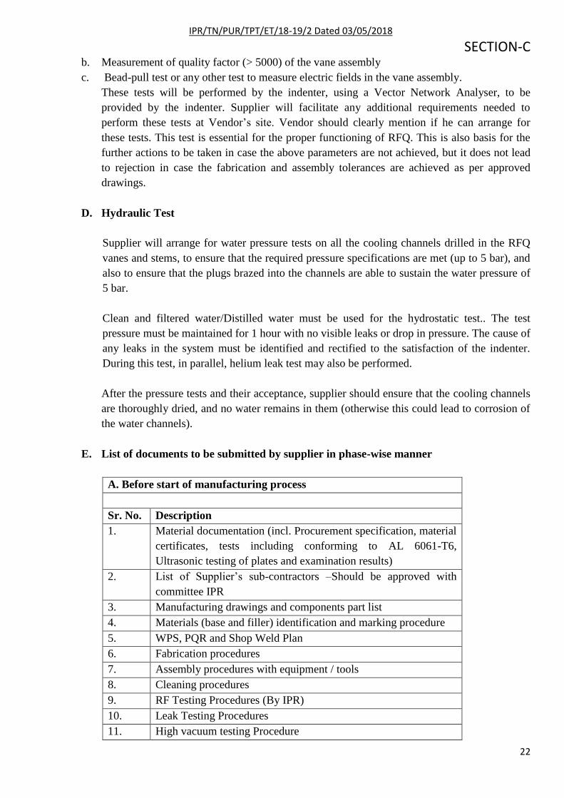
b. Measurement of quality factor (> 5000) of the vane assembly
c. Bead-pull test or any other test to measure electric fields in the vane assembly.
These tests will be performed by the indenter, using a Vector Network Analyser, to be
provided by the indenter. Supplier will facilitate any additional requirements needed to
perform these tests at Vendor‟s site. Vendor should clearly mention if he can arrange for
these tests. This test is essential for the proper functioning of RFQ. This is also basis for the
further actions to be taken in case the above parameters are not achieved, but it does not lead
to rejection in case the fabrication and assembly tolerances are achieved as per approved
drawings.
D. Hydraulic Test
Supplier will arrange for water pressure tests on all the cooling channels drilled in the RFQ
vanes and stems, to ensure that the required pressure specifications are met (up to 5 bar), and
also to ensure that the plugs brazed into the channels are able to sustain the water pressure of
5 bar.
Clean and filtered water/Distilled water must be used for the hydrostatic test.. The test
pressure must be maintained for 1 hour with no visible leaks or drop in pressure. The cause of
any leaks in the system must be identified and rectified to the satisfaction of the indenter.
During this test, in parallel, helium leak test may also be performed.
After the pressure tests and their acceptance, supplier should ensure that the cooling channels
are thoroughly dried, and no water remains in them (otherwise this could lead to corrosion of
the water channels).
E. List of documents to be submitted by supplier in phase-wise manner
A. Before start of manufacturing process
Sr. No. Description
1. Material documentation (incl. Procurement specification, material
certificates, tests including conforming to AL 6061-T6,
Ultrasonic testing of plates and examination results)
2. List of Supplier‟s sub-contractors –Should be approved with
committee IPR
3. Manufacturing drawings and components part list
4. Materials (base and filler) identification and marking procedure
5. WPS, PQR and Shop Weld Plan
6. Fabrication procedures
7. Assembly procedures with equipment / tools
8. Cleaning procedures
9. RF Testing Procedures (By IPR)
10. Leak Testing Procedures
11. High vacuum testing Procedure

IPR/TN/PUR/TPT/ET/18-19/2 Dated 03/05/2018
SECTION-C
23
12. Hydro Testing Procedures
13. List and status of equipment / instruments / tools for QC setup
14. List and status of equipment / instruments / tools for QC setup
with subcontractor
15. Packing and Transportation procedures
16. Non Conformance Report (If applicable)
B. Documents to be supplied before final acceptance in the factory
Sr. No. Description
1. Description
2. Inspection reports (dimensional checking, visual inspection,
results of leak tests performed (including size and location of
leaks found), Pressure/Vacuum Testing, Hydro testing, NDT,RF
testing.
3. End of manufacturing report (Release Note) including as built
drawings. (Soft Copy-as per the desired & approved format
Preferably CATIA V5 mutually agreed with IPR and Hard Copy).
Table 3: List of deliverables of Documents
Note: Apart from the list mentioned above as deliverables, any other item required for testing,
assembly to maintain mechanical integrity and to meet the requirements as fabrication of RFQ
Assembly & vacuum vessel with required covering flanges also comes under scope of supply.
F. MACHINING & WELDING
CRITERIA FOR MACHINING OF RFQ VANES AND STEMS
All machining shall comply with the specification laid down under the relevant Indian standard
for general tolerances.
Latest edition of the following shall be the applicable code / specification:
IS 2102(Part 1)/ISO 2768-1: Tolerances for Linear and Angular dimensions without individual
tolerance indications.
IS 6838: Dimensions for „O‟ Rings and Grooves for Vacuum Flanges.
IS 3073: Assessment of Surface Roughness.
IS 2709: Guide for selection of FITS.
Machining General Requirement:
Machining shall be done on the job, strictly following the approved Manufacturing and
Inspection Plan (MIP) using approved machining tools, fixtures and qualified machinist /
machine operators. Suitable sequencing of machining shall be carried out to avoid buildup of
residual stress and distortion.

IPR/TN/PUR/TPT/ET/18-19/2 Dated 03/05/2018
SECTION-C
24
The manufacturer shall prepare written procedure for distortion control for each typical
operation giving the sequence of machining; machine feed, speed to machining etc. and shall
submit the same to purchaser before taking up manufacturing. The same shall be displayed in
manufacturer‟s shop during machining. Clearance shall be obtained from the purchaser‟s
inspector for further machining. The sagging and distortion of the machined component shall be
measured and recorded. The required accuracy as per qualified Procedure should be maintained
by properly controlling speed, feed and usage of fixtures.
The machining processes shall be carried out using the base material and precise machines, tools
and fixtures.
Welding General Requirement:
Welding shall be done on the job, strictly following the approved welding procedures using
approved welding consumables and qualified welders / welding operators. Suitable sequencing
of welds shall be carried out to avoid buildup of residual stress and distortion.
The manufacturer shall prepare written procedure for distortion control for each typical joint
giving the sequence of welding; heat input to weld etc. and shall submit the same to purchaser
before taking up manufacture. The same shall be displayed in manufacturer‟s shop during
welding. Clearance shall be obtained from the purchaser‟s inspector for fit-up before welding.
The shrinkage and distortion of the welded joints shall be measured and recorded. The average
heat input as per qualified Procedure Quality Record (PQR) shall be maintained by properly
controlling voltage, current and welding speed during welding to meet the mechanical and
metallurgical properties.
All the welding consumable shall be manufactured, inspected, tested, packed, supplied and
stored as per the requirements of ASME Sec II Part C. Each batch of welding consumable is
required to be qualified at vendor‟s shop as per the requirements of ASME Sec II Part C.
All weld joints shall comply with the specification laid down under the relevant Subsections of
Article 1 of ASME standard for Boiler and Pressure vessels, section IX.
Latest edition of the following shall be the applicable code / specification:
ASME Sec IX: Welding and Brazing Qualification
ASME Sec V: Non-destructive Examination
ASME Sec II Part C: Specifications for Welding Vanes, Electrodes and Filler Metals.
Acceptance tests for welds:
The welding processes shall be carried out using the same base material and filler materials.
Radiographic inspection:
Weld samples shall be subjected to radiographic inspection according to QW191 of ASME
standard for Boiler & Pressure vessels section IX.

IPR/TN/PUR/TPT/ET/18-19/2 Dated 03/05/2018
SECTION-C
25
The welding quality shall be checked on welding samples produced during fabrication under
identical conditions for, and in parallel with, the actual fabrication welding. The number of
samples will be agreed in writing between the vendor and IPR. The vendor shall initiate
manufacturing only after receiving the written approval of IPR related to the acceptance tests.
G. INSPECTION and TESTING
i. The supplier shall inspect all the parts, sub-assemblies, final assemblies etc., for full
compliances as per approved drawings.
ii. All measurement should be carried out with highly precise measuring instrument i.e. CMM
(Co-ordinate Measuring Machine), Laser Tracker, Articulated Arm.
iii. All the tolerance dimensions / features in the individual parts and the completed vessel shall
be inspected by suitable methods.
iv. Dimensional check for the individual components and the completed vessel shall be carried
out at a constant temperature as per the approved procedure and shall meet the requirements
specified in the approved drawing.
v. Before dimensional checks all the tools, gauges, instruments and measuring equipment‟s
must be calibrated to ensure their proper range, type, accuracy & precision.
vi. Inspection of welds must be as per criterion mention in section 9.
vii. Helium leak test with vacuum must be done on finally fabricated and cleaned vacuum vessel
as per final acceptance criterion mentioned in section 11.
viii. High Vacuum (HV) Test must be done after the successfully completion of helium leak
testing as per acceptance criterion mentioned in section 11.
ix. The supplier shall provide details of all the inspection and testing facilities. The inspection
and testing shall be done in a manner acceptable to purchaser. If deemed necessary purchaser
will have right to specify additional inspection / testing other than specified in this
specification and cost of such test / inspection will be borne by the purchaser. The records of
all the tests and inspection shall be maintained by the supplier and the same will be submitted
to the purchaser.
x. Quality surveillance as well as quality audit by the purchaser or his authorized representative
shall not relieve the supplier from the responsibility of meeting the specification or the
inspection duties.
xi. The inspection shall be in compliance with MIP prepared by the supplier and approved by the
purchaser. However depending on the manufacturing procedure, quality assurance system of
the company and manufacturing and inspection facilities available with the supplier, some
additional checks may also be necessary on and above approved MIP. Such checks shall be
incorporated and implemented by the supplier without any extra financial implications to the
purchaser.

IPR/TN/PUR/TPT/ET/18-19/2 Dated 03/05/2018
SECTION-C
26
xii. Written reports to be reviewed and signed by authorized representative of the vendor for each
test and inspection.
xiii. IPR should be informed before planning of any test well in advance. IPR representative will
witness these tests. Acceptance of any component will only be given once full requirements
of the specification and/or drawings are achieved. In the event of a test failure, the vendor
shall document the failure and submit a proposal for correcting the faults. Written approval
from IPR shall be required before any corrective action is taken.
xiv. The vendor shall verify the work at various steps/check points as described in the
specifications. The work shall be inspected and tested at each stage of manufacture to ensure
conformity with the requirements specified therein and to enforce quality control measures.
xv. The quality control tasks shall be carried out by a unit of the vendor‟s organization that is
independent of the production/manufacturing unit and reports directly to the management.
xvi. The entire documentation for the inspection and tests shall be recorded suitably with date,
supporting data of the observations and duly certified with the signature of the quality control
personnel. These records shall be easily and freely accessible to the authorized representative
of IPR and he will also witness quality control activities for critical processes and operations.
5. MATERIAL PROCUREMENT Complete list of free-issue-material is shown in the Annexure-A. The materials undergoing
fabrication procedures shall be protected against damage/distortion by mishandling, scratches,
denting or effects of weather.
An essential functional requirement for internal surface of RFQ structure is high quality surface
finish, free of any embedded particulate contamination such as abrasive particles. Otherwise also, the
OFE copper is a very soft material, which must be protected from any sort of surface damage
specially on inner cavity walls of RFQ.
After completion of the work as per the drawings, Left over material should be returned to IPR.
All the material, welding consumable, proprietary items and brought out items including materials
for trials, qualifications and test coupons etc., as required for manufacturing of the vacuum vessel
shall be procured in accordance with relevant ASTM specification with appropriate test certificates.
The supplier shall procure all the materials as per relevant applicable specification from reputed
manufacturers and not through agents. The source of material procurement shall also be indicated
and got approved from the purchaser. MIP, QP, testing procedure, Non Destructive Examination
(NDE) procedure etc. submitted by the suppliers of raw materials, welding consumables, and
proprietary items and brought out items shall be submitted to the purchaser for approval before
procurement of material. Approved MIP and QP shall be strictly followed thereafter during
procurement.

IPR/TN/PUR/TPT/ET/18-19/2 Dated 03/05/2018
SECTION-C
27
5.1 MATERIAL SPECIFICATION
Sr.No. Component Material Equivalent grade
1. VACUUM VESSEL IN TWO
IDENTICAL RECTANGLES
AL 6061-T6 ASTM B209M – 14,AL
6061-T6
2. Covering Flanges of Vacuum
Vessel with O ring Grooves
AL 6061-T6 ASTM B209M – 14,AL
6061-T6
3. Ports on vacuum vessel AL 6061-
T6/SS316
ASTM B209M−14,AL
6061-T6/ASTM A-240
4. Vane/Stem material Oxygen Free
Electronic (OFE)
copper
ASTM B170-99, grade 1
UNS C10100
5. Base Plate ETP Copper ASTM B 152/ B152 M,
Copper C11000
6. Filler wire for AL 6061-T6 ER 4043 AWS A5.10/A5.10M:2017
7. Brazing foils for end plugs BAg-8 AWS A5-8
8. Bolts , studs, insert & Nuts
,washer, Dowel pins
Stainless steel ASTM A-193 non
magnetic
The dimensions mentioned in the drawings are finished dimensions and the supplier shall procure the
material in sufficient quantities and appropriate size taking into account all the necessary allowances
required for manufacture, qualification and testing.
Testing of material to meet the specification of equivalent ASTM Grade is to be carried out by vendor and
certification for all the material tests is to be provided to IPR. All material shall be free from all the kinds of
defects like porosity, cracks, fissures, dents, pits, lamination or any other defects which would make it
incompatible with ultra-high vacuum environment. Following test must be performed to comply with
specification:
1. Chemical Analysis test
2. Tensile strength test
Vendor must agree for a laboratory test in govt. approved test laboratories in presence of IPR
representatives.
Surface finish of material:
The inner surface (expose to Vacuum) must be ~3 micron and it must be dent and scratch free. The
region of the flanges, where wire seals, CF seals and O-rings are to be placed, must attain a surface
finish of ~ 3 micron and should be free from any scratch. The outer surface must be free from sharp
edges. Components shall be cleaned with NaOH and water to remove traces of acid left after electro-
polishing.

IPR/TN/PUR/TPT/ET/18-19/2 Dated 03/05/2018
SECTION-C
28
6. CLEANINESS, STORAGE AND WORKMANSHIP
Prior to its helium leak test, the vacuum vessel shall be cleaned. All internal and external surfaces of
the vacuum vessel, including all flanges shall be rendered free from fingerprints, contamination,
welding flux, and any other substance that may impair the ability to establish and maintain the
required vacuum. After cleaning, the vacuum vessel shall be closed with airtight covers and stored
under clean polyethylene covers in a clean, dry and dust free area. Remove oil, grease, and water
vapor using an organic solvent such as acetone or a mild alkaline solution like a strong soap. Remove
surface oxides with a stainless steel wire brush (used only for aluminum) or strong alkaline or acid.
shall be followed by detergent cleaning.
Suggested Procedure for cleaning of copper component:
1. Cleaning using citric acid dilute solution, rinsing with fresh water, again cleaning with
isopropyl alcohol and packing
2. Chemical Cleaning in stages as listed below:
a. First Etching with dilute sulphuric or nitric acid solution (Ratio 20: 100) for about 1min or
less.
b. Second rinsing with clean water
c. Cleaning with detergent powder thoroughly
d. Again rinse with clean water
e. Dip in dilute chromic acid solution (Ratio 20: 100) for about half to 1 minute based on trial.
f. Rinse with fresh water
g. Drying with hot air
h. cleaning with isopropyl alcohol and packing
Note: Second method is just like as passivation, in which copper surface get fine chrome layer,
which can last for months or years if it protected well means air tight.
7. HANDLING, PACKAGING and TESTING
The procedures for the handling and storage of Copper and Copper alloys are very similar to
those used for Aluminum and Stainless Steel. It should be noted that the products are heavy, but
relatively soft and can thus be easily damaged through poor or inappropriate handling.
i. Copper bars should remain in their packaging until required and should be kept separated by
protective material to avoid abrasion between the bars. Equally, the products must be
protected from water, dampness and condensation.
ii. Where Necessary, Finished component and bars should be stored in covered racks.
iii. The bidder shall give details of floor space and suitable handling facilities available at the
place of manufacture, assembly and testing of vacuum vessel parts and assemblies at the time
of bidding.
iv. The supplier shall ensure that all the vessel parts / assemblies / surfaces of the material are
protected by proper covering against any corrosion or damage during all stages of
manufacture, inspection, handling, storage and transport. The packing shall be suitable and
rigid enough to ensure safety of vessel during all stages of shipping by road to site, loading,

IPR/TN/PUR/TPT/ET/18-19/2 Dated 03/05/2018
SECTION-C
29
stacking and storage at plant site. Adequate number of silica gel packets along with a copy of
shipping release shall be kept inside carte.
v. All the openings shall be protected to prevent entrance of dirt and moisture during shipment,
storage at site and erection.
vi. The package shall be stenciled in bold character with indelible paint, protected with shellac to
indicate shipping mark, package numbers, dimensions and gross weight in kilos, the purchase
order number and any other necessary data to identify the equipment and relate it to the
contract.
vii. Packing list shall plainly show package number, kinds of package, contents, dimensions and
net, legal and gross weight of each package. If different items are in a package, the net weight
for each item shall be specified.
viii. The shipment of equipment shall not be effected until and unless written “Inspection Release
Note” / “Shipping Release” / “Dispatch Clearance” is obtained. The same will be issued by
the purchaser or his authorized representative at contractor‟s work after satisfactory
completion of “Factory acceptance test”. The supplier then only shall dispatch the vessel to
purchaser‟s site.
ix. Transshipment in transit shall be avoided and supplier shall arrange specially hired
conveyance for direct delivery at purchaser‟s site.
8. DRAWINGS
8.1. Engineering Drawings:
The drawings for the preliminary design, prepared by CATIA, would be provided by IPR and
are applicable as per annexure-D.
8.2. Manufacturing Drawing: The supplier shall prepare manufacturing / shop drawing based on final design approved by
purchaser. The drawings prepared by the supplier shall require the approval of the purchaser
prior to start of manufacturing activities. The supplier shall take care to prepare detailed shop
manufacturing drawings / sketches indicating all the dimensions with tolerances for all the
individual components, sub-assemblies, final assemblies etc.
The vendor needs to prepare the „as built‟ drawing after completion of all the manufacturing and
testing activities and the same shall be submitted to purchaser for review and approval.

IPR/TN/PUR/TPT/ET/18-19/2 Dated 03/05/2018
SECTION-C
30
9. DELIVERY The RFQ assembly and Vacuum vessel covered by this tender document should be
supplied, delivered and unloaded at IPR site within nine months from the date of approval
of fabrication drawings by IPR. Prototype should be ready for testing within 4 months
from the date of approval of fabrication drawings. The vender should submit fabrication
drawings for IPR approval within 5 weeks from the date of LOI.
10. INFORMATION REQUIRED WITH BID PROPOSAL
1. Technical Bid Format and Bidder's Confirmation as per Annexure-C enclosed with this document is
to be furnished in full along with above requirements asked.

IPR/TN/PUR/TPT/ET/18-19/2 Dated 03/05/2018
SECTION-C
31
Annexure-A: Free Issue Material
Oxygen Free Electronic (OFE) copper extruded bars, conforming to ASTM B170-99, grade shall be
supplied by IPR as free issue items. This material is guaranteed for freedom from hydrogen
embrittlement and tested according to method D of ASTM B577-93
Sr. no. Description Quantity
1 OFE Copper Bars for Stems: 140 mm x 270 mm x 920mm or
bigger
04 approx
2 OFE Copper Bars for Vanes: 140 mm x 100mm x 920mm or
bigger
07 approx
NOTE: As the material will be supplied by IPR and it is costly material (Aprox.Rs.900/-per kg) in case
of rejection, a maximum of 25% of total raw material, if required from vendor‟s side, will be issued free,
against the rejected components. Over and above will be deducted at the rate of Rs.900/ (Rupees Nine
Hundred) per Kg from the final bill.
Total value of FIM is approx. Rs.1,600,000/-

IPR/TN/PUR/TPT/ET/18-19/2 Dated 03/05/2018
SECTION-C
32
ANNEXURE-B (Mandatory Conditions)
Preliminary Information:
The fabrication of 4-Rod Radio Frequency Quadrupole (RFQ) is very intricate process in terms of
precision and shape. The rods/vanes tips are having irregular modulations. These modulations take the
special curved shape. This shape should be maintained within the précised tolerance of 10-20 m
because the resonant frequency of RFQ cavity is very sensitive to mechanical deformation, specially, on
vane tips. Similar kinds of tolerances are required to be maintained during assembly of vanes and stems
of RFQ. The fabrication of vanes and stems requires high precision CNC machines, CMM etc.
Mandatory Conditions:
Note: As part of technical acceptance, bidder must comply with following conditions for this tender:
1. Bidder must have good fabrication facilities which include C.N.C 5- AXIS MILLING MACHINE,
CNC wire cut machine, Surface/Universal grinding machine, Universal milling & boring machine
with D.R.O. The vendor must provide the list of machinery along with its technical specifications
that are required and their availability to execute the job.
2. Bidder should possess or arrange at a 3rd
party premises the metrology required for the measurement
and testing like including CMM machines, linear height master, Surface roughness tester in their
workshops. Documentary proof for the same must be provided. Consent letter from 3rd
party shall be
furnished wherever applicable.
3. In case the Bidder is sub-contracting the fabrication and test of vacuum system, consent letter from
the sub-contract shall be furnished as applicable.
4. List of bidder‟s sub-contract suppliers with their undertaking for this tender to be submitted.
5. The bidder should submit a declaration with regard to Projects on-hand with cost details for the
next Three (3) years.

IPR/TN/PUR/TPT/ET/18-19/2 Dated 03/05/2018
SECTION-C
33
ANNEXURE-C: Technical Bid Format
A. Bidder's Experience: (to be provided by Bidder)
B. Required Infrastructure to execute the job: (Bidder has to list down all the required machines /
metrology / infrastructure etc.). If the bidder don’t have the required infrastructure then he should
mention clearly the name of sub-contractor.
Sr.
No.
Required to execute the job Availability with bidder /
Sub-contractor
1
2
3
4
5
6
7
8
9
10
11
12
13
C. Quality System and Assurance: (Bidder has to provide the details to maintain the QA / QC during
the execution of job)
D. Codes and Standards: (Bidder has to mention the name of codes and standards to be followed)

IPR/TN/PUR/TPT/ET/18-19/2 Dated 03/05/2018
SECTION-C
34
E. Technical Compliance Sheet for RFQ assembly &Vacuum Vessel:
RFQ assembly &Vacuum Vessel to be delivered as follows:
Sr.
No.
Scope of Supply Bidder’s
confirmation
1 Evaluation and analysis of design to meet the specified
design and operation condition, suggest changes if required,
implementation of those changes in concurrence with the
purchaser
2. Preparation of shop drawings for manufacture in shop,
manufacturing and quality documents such as Manufacturing
and Inspection Plan (MIP), Quality Plan (QP),
manufacturing process sheets, manufacturing procedures,
welding procedures, assembly procedures, inspection and
testing procedures, packing & transportation procedures, etc.
3. Procurement of all the materials required for the job
including those for qualifications (welding and forming) and
for production test coupons (if required) etc, as per the
specification and manufacture, assembly, inspection, testing,
surface treatment, packing.
4. Manufacture the equipment as per the drawings and
specification with the optimum and efficient method of
manufacturing to meet the design and operational
requirements.
5. Design and manufacture (with supplier‟s material) of dyes,
punches, jigs, fixtures and tooling required for manufacture,
handling assembly, inspection and testing of vessel is in the
scope of supplier.
6. Design, manufacture (with supplier‟s material), supply and
guarantee of special transportation structure and handling
tools / fixtures for handling vessel at purchaser‟s site. The
design of packing / transportation structure shall be such
that, when lifted by crane at site, alone gets lifted leaving
behind the packing structure.
7. Carry out inspection and tests at various stages before / after
/ during manufacturing as asked by the various sections and
annexures of this specification and drawing.
8. The issuance of “Inspection Release Note” / “Shipping
Release” / “Dispatch Clearance” from the purchaser or his
authorized representative shall be considered as “Factory
acceptance test”
9. Loading, safe delivery, transportation, handling, unloading at
identified location at IPR site, installation and vacuum
testing at IPR site. The vessel shall be handled in such a

IPR/TN/PUR/TPT/ET/18-19/2 Dated 03/05/2018
SECTION-C
35
manner that it remains horizontal all the time and no load
acts upon it.
10. Carry out site acceptance test which may contain overall
dimensional inspection, visual inspection for verification of
transportation damages, and leak testing in presence of
purchaser‟s representative.
11. Responsibility of vessel functionality
F. Compliance sheet for RFQ fabrication
Compliance Sheet For RFQ Fabrication
S.No Parameter IPR Requirement Vender
Specification
1. Vane Machining Accuracy 20 µm
2. RFQ Vane Alignment Accuracy Better than ±50 µm
3. Inter-segment Alignment Accuracy Better than ±50 µm
4. Max transverse position error
(X,Y)at upstream and
downstream beam flange
Better than ±100 µm
5. Max longitudinal position error (Z) Better than ±100 µm
6. Leak rate for Vacuum vessel and
RFQ Assembly
< 1x 10⁻⁹
mbar lt/sec
7. Surface Flatness of all components
as mentioned in the respective
drawings e.g Base Plate
Within ±0.02mm.
8. Alignment of all components as per respective drawings
G. Spares to be supplied for RFQ assembly and Vacuum Vessel:
Spare to be supplied by the bidder:
Any other spares which are needed for functioning of vessel as per the design and Operation requirements
are to be supplied along with the vessel.
H. Bidder’s deviations from technical specifications, terms and conditions, if other than specified in
part-A and associated appendices:
Bidder may specify his deviation from technical specifications, terms and conditions, if other than specified
in Part-A & its appendices. However these changes will become applicable on technical merit after
discussion with purchaser and acceptance of the same by purchaser. Any noncompliance shall be
unambiguously highlighted by the bidder.

IPR/TN/PUR/TPT/ET/18-19/2 Dated 03/05/2018
SECTION-C
36
I. Any additional information bidder wants to give in support of his bid.
K. Delivery schedule along with project execution milestone chart.
K. Confirmation letter from bidder:
Bidder will attach a confirmation letter with Part-A of the bid confirming that vendor has have studied all
documents and drawings of Tender notice for Manufacturing, Inspection, supply, installation and final
acceptance at IPR site of “RFQ assembly and Vacuum Vessel”. And also must confirm that Price Bid is
in-line with the terms and conditions, management specifications and technical specifications given in this
tender.” Vendor should put his authorized signature and official stamp on the confirmation with date and
place of signing.

IPR/TN/PUR/TPT/ET/18-19/2 Dated 03/05/2018
SECTION-C
37
ANNEXURE –D: List of Drawings
List of drawings:

IPR/TN/PUR/TPT/ET/18-19/2 Dated 03/05/2018
SECTION-C
38

39