Radio Access Network (RAN) Signalling …epubs.surrey.ac.uk/811126/1/PhDThesisReport.pdfRadio Access...
130
Radio Access Network (RAN) Signalling Architecture for Dense Mobile Networks Joseph Stalin Thainesh Submitted for the Degree of Doctor of Philosophy from the University of Surrey Institute for Communication Systems (ICS) University of Surrey Guildford, Surrey GU2 7XH, UK July 2016 c Joseph Stalin Thainesh 2016
Transcript of Radio Access Network (RAN) Signalling …epubs.surrey.ac.uk/811126/1/PhDThesisReport.pdfRadio Access...

Radio Access Network (RAN) SignallingArchitecture for Dense Mobile Networks
Joseph Stalin Thainesh
Submitted for the Degree ofDoctor of Philosophy
from theUniversity of Surrey
Institute for Communication Systems (ICS)University of Surrey
Guildford, Surrey GU2 7XH, UK
July 2016
c© Joseph Stalin Thainesh 2016


Abstract
Small cells are becoming a promising solution for providing enhanced coverage andincreasing system capacity in a large-scale small cell network. In such a network, thelarge number of small cells may cause mobility signalling overload on the core network(CN) due to frequent handovers, which impact the users Quality of Experience (QoE).This is one of the major challenges in dense small cell networks. Such a challengehas been considered, this thesis addresses this challenging task to design an effectivesignalling architecture in dense small cell networks.
First, in order to reduce the signalling overhead incurred by path switching opera-tions in the small cell network, a new mobility control function, termed the Small CellController (SCC) is introduced to the existing base station (BS) on the Radio-Access-Network(RAN)-side. Based on the signalling architecture, a clustering optimisationalgorithm is proposed in order to select the optimal SCC in a highly user density envi-ronment. Specifically, this algorithm is designed to select multiple optimal SCCs dueto the growth in number of small cells in the large-scale environment. Finally, a scal-able architecture for handling the control plane failures in heterogeneous networks isproposed. In that architecture, the proposed SCC scheme controls and manages theaffected small cells in a clustered fashion during the macro cell fail-over period. Par-ticularly, the proposed SCC scheme can be flexibly configured into a hybrid scenario.
For operational reduction (reducing a number of direct S1 connections to the CN), bet-ter scalability (reducing a number of S1 bearers on the CN) and reduction of signallingload on the CN, the proposed radio access network (RAN) signalling architecture isa viable and preferable option for dense small cell networks. Besides, the proposedsignalling architecture is evaluated through realistic simulation studies.
Key words: Cluster formation, Control plane, Controller Selection, Mobility manage-ment, Small cells, Signalling load, X2-handover
Email: [email protected]
WWW: http://www.eps.surrey.ac.uk/

Acknowledgements
First, I would like to express my sincere gratitude to my supervisor Prof.Rahim Tafa-zolli for his continuous support, motivation and guidance. I’m also grateful to myco-supervisor Dr.Ning Wang. I’m extremely thankful for his numerous suggestions,technical discussions and guidance throughout my research study. I would also want toexpress my deep gratitude to Dr.Anastasios Karousos and Dr.Konstantinos Katsarosfor their valuable comments.
Further, I would like to express my gratitude to all of the Institute for CommunicationSystems (ICS) members for their help and support. Specifically, I would like to thankthe ICS admin staff for their assistance in many ways.
Finally, I am forever indebted to my family for their love, support and encourage-ment. Their belief in me during my entire life, especially during my studies made thisendeavour simple.

Contents
Glossary of Terms xvii
1 Introduction 1
1.1 Introduction . . . . . . . . . . . . . . . . . . . . . . . . . . . . . . . . . . 1
1.2 Motivation and Objectives . . . . . . . . . . . . . . . . . . . . . . . . . . 3
1.3 Main Contributions . . . . . . . . . . . . . . . . . . . . . . . . . . . . . . 5
1.4 Organization of the Thesis . . . . . . . . . . . . . . . . . . . . . . . . . . 7
2 Literature Review 9
2.1 Small Cell Network Architecture . . . . . . . . . . . . . . . . . . . . . . 9
2.2 Functional Overview . . . . . . . . . . . . . . . . . . . . . . . . . . . . . 11
2.2.1 Small cell . . . . . . . . . . . . . . . . . . . . . . . . . . . . . . . 12
2.2.2 MME . . . . . . . . . . . . . . . . . . . . . . . . . . . . . . . . . 12
2.2.3 SGW . . . . . . . . . . . . . . . . . . . . . . . . . . . . . . . . . 13
2.2.4 PGW . . . . . . . . . . . . . . . . . . . . . . . . . . . . . . . . . 13
2.3 Mobility Management . . . . . . . . . . . . . . . . . . . . . . . . . . . . 14
2.3.1 Idle Mode Mobility . . . . . . . . . . . . . . . . . . . . . . . . . . 14
2.3.1.1 PLMN Selection . . . . . . . . . . . . . . . . . . . . . . 14
2.3.1.2 Cell Selection and Reselection . . . . . . . . . . . . . . 14
2.3.1.3 Location Management . . . . . . . . . . . . . . . . . . . 15
2.3.2 Connected Mode Mobility . . . . . . . . . . . . . . . . . . . . . . 16
2.3.3 Comparison Summary of Mobility Management . . . . . . . . . . 23
2.4 Coverage and Interference Management . . . . . . . . . . . . . . . . . . 24
2.4.1 Comparison Summary of Coverage and Interference Management 26
2.5 Summary . . . . . . . . . . . . . . . . . . . . . . . . . . . . . . . . . . . 27
v

vi Contents
3 RAN Signalling Architecture for Dense Mobile Networks 29
3.1 Introduction . . . . . . . . . . . . . . . . . . . . . . . . . . . . . . . . . . 29
3.2 The SCC based Small Cell Networks . . . . . . . . . . . . . . . . . . . . 30
3.2.1 Main Procedures of the SCC . . . . . . . . . . . . . . . . . . . . 31
3.2.1.1 X2 configuration setup . . . . . . . . . . . . . . . . . . 32
3.2.1.2 X2 based handover . . . . . . . . . . . . . . . . . . . . . 32
3.2.1.3 Bearer setup . . . . . . . . . . . . . . . . . . . . . . . . 32
3.3 Mobility Management . . . . . . . . . . . . . . . . . . . . . . . . . . . . 33
3.3.1 Intra SCC Cluster based Mobility Management . . . . . . . . . . 33
3.3.1.1 X2 based IntraSToS handover . . . . . . . . . . . . . . 33
3.3.1.2 X2 based IntraSToSCC handover . . . . . . . . . . . . . 35
3.3.1.3 X2 based IntraSCCToS handover . . . . . . . . . . . . . 35
3.3.2 Inter SCC Cluster based Mobility Management . . . . . . . . . . 39
3.3.2.1 X2 based InterSToS handover . . . . . . . . . . . . . . 39
3.3.2.2 X2 based InterSToSCC handover . . . . . . . . . . . . . 41
3.3.2.3 X2 based InterSCCToS handover . . . . . . . . . . . . . 41
3.3.2.4 X2 based InterSCCToSCC handover . . . . . . . . . . . 42
3.3.3 Placement of the SCC in a cluster . . . . . . . . . . . . . . . . . 46
3.4 Mobility Performance Metrics . . . . . . . . . . . . . . . . . . . . . . . . 48
3.4.1 Signalling and Data Forwarding Cost per UE . . . . . . . . . . . 48
3.4.1.1 Intra SCC cluster based handover . . . . . . . . . . . . 48
3.4.1.2 Inter SCC cluster based handover . . . . . . . . . . . . 49
3.4.2 Signalling Load . . . . . . . . . . . . . . . . . . . . . . . . . . . . 51
3.4.2.1 Signalling Load at the MME . . . . . . . . . . . . . . . 51
3.4.2.2 Signalling Load at the SCC . . . . . . . . . . . . . . . . 52
3.5 Performance Analysis . . . . . . . . . . . . . . . . . . . . . . . . . . . . 53
3.5.1 Signalling Load at the CN . . . . . . . . . . . . . . . . . . . . . . 55
3.5.2 Signalling and Data Delivery Latency per UE . . . . . . . . . . . 57
3.5.3 Impact of the SCC Mobility Schemes on Handover Performance . 59
3.5.4 Performance Analysis of the Signalling Load Reduction at the CN 61
3.6 Summary . . . . . . . . . . . . . . . . . . . . . . . . . . . . . . . . . . . 63

Contents vii
4 A Clustering Optimisation Approach in Dense Mobile Networks 65
4.1 Introduction . . . . . . . . . . . . . . . . . . . . . . . . . . . . . . . . . . 65
4.2 A Scalable Clustering based Approach for the SCC . . . . . . . . . . . . 66
4.2.1 The Clustering Optimisation Algorithm . . . . . . . . . . . . . . 67
4.2.2 Example of the Clustering Optimization Algorithm . . . . . . . . 70
4.3 Performance Analysis . . . . . . . . . . . . . . . . . . . . . . . . . . . . 72
4.3.1 Signalling Load at the CN . . . . . . . . . . . . . . . . . . . . . . 73
4.3.2 Signalling and Data Delivery Latency per UE . . . . . . . . . . . 77
4.3.3 Signalling load at the SCC . . . . . . . . . . . . . . . . . . . . . 79
4.4 Summary . . . . . . . . . . . . . . . . . . . . . . . . . . . . . . . . . . . 81
5 A Scalable Architecture for Handling Control Plane Failures in Het-erogeneous Networks 83
5.1 Introduction . . . . . . . . . . . . . . . . . . . . . . . . . . . . . . . . . . 83
5.2 A Macro cell goes down in Heterogeneous Networks . . . . . . . . . . . 84
5.2.1 The Legacy Procedure . . . . . . . . . . . . . . . . . . . . . . . . 84
5.2.2 The Proposed Procedure . . . . . . . . . . . . . . . . . . . . . . . 86
5.3 The SCC Cluster based Heterogeneous Network . . . . . . . . . . . . . . 87
5.4 A Hybrid Configuration Scenario . . . . . . . . . . . . . . . . . . . . . . 89
5.5 Performance Analysis . . . . . . . . . . . . . . . . . . . . . . . . . . . . 92
5.5.1 Signalling and Data Delivery Latency per UE . . . . . . . . . . . 93
5.5.2 Signalling Load at the CN . . . . . . . . . . . . . . . . . . . . . . 95
5.6 Summary . . . . . . . . . . . . . . . . . . . . . . . . . . . . . . . . . . . 98
6 Conclusions and Future Work 99
6.1 Conclusions . . . . . . . . . . . . . . . . . . . . . . . . . . . . . . . . . . 99
6.2 Future Works . . . . . . . . . . . . . . . . . . . . . . . . . . . . . . . . . 101
Bibliography 103

viii Contents

List of Figures
1.1 Small cell networks . . . . . . . . . . . . . . . . . . . . . . . . . . . . . . 2
2.1 Small cell network architecture . . . . . . . . . . . . . . . . . . . . . . . 10
2.2 Functional Split between E-UTRAN and EPC . . . . . . . . . . . . . . . 11
2.3 X2 based handover . . . . . . . . . . . . . . . . . . . . . . . . . . . . . . 17
2.4 Local anchor based handover architecture . . . . . . . . . . . . . . . . . 20
3.1 The SCC based small cell networks . . . . . . . . . . . . . . . . . . . . . 30
3.2 X2 based, IntraSToS handover procedure . . . . . . . . . . . . . . . . . 34
3.3 X2 based, IntraSToSCC handover procedure . . . . . . . . . . . . . . . . 36
3.4 X2 based, IntraSCCToS handover procedure . . . . . . . . . . . . . . . . 37
3.5 An example of intra SCC cluster scenario . . . . . . . . . . . . . . . . . 38
3.6 X2 based, InterSToS handover procedure . . . . . . . . . . . . . . . . . . 40
3.7 X2 based, InterSToSCC handover procedure . . . . . . . . . . . . . . . . 42
3.8 X2 based, InterSCCToS handover procedure . . . . . . . . . . . . . . . . 43
3.9 X2 based, InterSCCToSCC handover procedure . . . . . . . . . . . . . . 44
3.10 An example of inter SCC cluster scenario . . . . . . . . . . . . . . . . . 45
3.11 SCC at center in a cluster . . . . . . . . . . . . . . . . . . . . . . . . . . 46
3.12 SCC at edge in a cluster . . . . . . . . . . . . . . . . . . . . . . . . . . . 47
3.13 Effect of cell size: Total handover signalling load at the MME . . . . . . 56
3.14 Effect of user velocity: Total handover signalling load at the MME (Thenumber of clusters is fixed) . . . . . . . . . . . . . . . . . . . . . . . . . 57
3.15 Effect of cell size: Signalling and data delivery latency per UE . . . . . 58
3.16 Effect of user velocity: Signalling and data delivery latency per UE . . . 59
3.17 Effect of cell size: Total percentage of intra SCC based handover sig-nalling load at the CN . . . . . . . . . . . . . . . . . . . . . . . . . . . . 60
ix

x List of Figures
3.18 Effect of cell size: Total percentage of inter SCC based handover sig-nalling load at the CN . . . . . . . . . . . . . . . . . . . . . . . . . . . . 60
3.19 Effect of user velocity: Total percentage of intra SCC based handoversignalling load at the CN . . . . . . . . . . . . . . . . . . . . . . . . . . 61
3.20 Effect of user velocity: Total percentage of inter SCC based handoversignalling load at the CN . . . . . . . . . . . . . . . . . . . . . . . . . . 61
3.21 Effect of cell size: Total percentage of reduction in handover signallingload at the CN . . . . . . . . . . . . . . . . . . . . . . . . . . . . . . . . 62
3.22 Effect of user velocity: Total percentage of reduction in handover sig-nalling load at the CN (The number of clusters is fixed) . . . . . . . . . 62
4.1 Algorithm 2: Compute Common Neigbhours . . . . . . . . . . . . . . . 69
4.2 An example of algorithm output scenario 1 . . . . . . . . . . . . . . . . 70
4.3 An example of algorithm output scenario 2 . . . . . . . . . . . . . . . . 71
4.4 Effect of small cells: Total handover signalling load at the MME (Thenumber of SCCs is fixed) . . . . . . . . . . . . . . . . . . . . . . . . . . 74
4.5 Effect of user velocity: Total handover signalling load at the MME . . . 75
4.6 Effect of user density: Total handover signalling load at the MME . . . 76
4.7 Effect of the number of small cells: Signalling and data delivery latencyper UE . . . . . . . . . . . . . . . . . . . . . . . . . . . . . . . . . . . . . 77
4.8 Effect of user velocity and the number of SCCs: Signalling and datadelivery latency per UE . . . . . . . . . . . . . . . . . . . . . . . . . . . 78
4.9 Effect of the number of small cells: Total handover signalling load at theSCC (The number of SCCs is fixed) . . . . . . . . . . . . . . . . . . . . 79
4.10 Effect of user velocity: Total percentage of reduction in handover sig-nalling load at the SCC in comparison with single SCC . . . . . . . . . 80
4.11 Effect of user density: Total percentage of reduction in handover sig-nalling load at the SCC in comparison with single SCC . . . . . . . . . 81
5.1 A macro cell goes down in the heterogeneous network. . . . . . . . . . . 85
5.2 A hybrid configuration, some of small cells are controlled by the SCC . 89
5.3 Example of hexagonal ring structure in the hybrid scenario . . . . . . . 91
5.4 Effect of user velocity and ring size: Signalling and data delivery latencyper UE . . . . . . . . . . . . . . . . . . . . . . . . . . . . . . . . . . . . . 93
5.5 Effect of cell size: Signalling and data delivery latency per UE . . . . . 94
5.6 Effect of cell size: Total handover signalling load at the MME . . . . . . 95

List of Figures xi
5.7 Effect of user velocity and ring size: Total handover signalling load atthe MME . . . . . . . . . . . . . . . . . . . . . . . . . . . . . . . . . . . 96
5.8 Effect of user density and ring size: Total handover signalling load atthe MME . . . . . . . . . . . . . . . . . . . . . . . . . . . . . . . . . . . 97

xii List of Figures

List of Tables
2.1 Comparison Summary of Mobility Management Schemes . . . . . . . . . 23
2.2 Comparison Summary of Coverage and Interference Management Schemes 26
3.1 Simulation Main Parameters . . . . . . . . . . . . . . . . . . . . . . . . 54
3.2 Cost Parameters . . . . . . . . . . . . . . . . . . . . . . . . . . . . . . . 55
6.1 Comparison between the cluster based approach and hybrid based ap-proach in small cell networks . . . . . . . . . . . . . . . . . . . . . . . . 101
xiii

xiv List of Tables

Glossary of Terms
3G Third Generation
3GPP Third Generation Partnership Project
3GPP2 Third Generation Partnership Project 2
AGW Anchor Gateway
AMBR Aggregate Maximum Bit Rate
APN Access Point Name
CCO Coverage and Capacity Optimization
CIP Cellular IP
CN Core Network
CP Control Plane
DC Dual Connectivity
DES Discrete-Event Simulation
DL Downlink
E −RAB E-UTRAN Radio Access Bearer
E − UTRAN Evolved UMTS Radio Access Network
eNB Evolved NodeB
EPC Evolved Packet Core
EPS Evolved Packet System
EUTRA Evolved UMTS Radio Access
GGSN Gateway GPRS Support Node
GSM Global System for Mobile Communications
GSN GPRS Support Node
xv

xvi List of Tables
GTP GPRS Tunnelling Protocol
GW Gateway
HeNB Home Evolved NodeB
HeNB −GW HeNB Gateway
HO Handover
ICI Inter-Cell Interference
IETF Internet Engineering Task Force
LAU Location Area Update
LTE Long Term Evolution
LTE −A Long Term Evolution-Advanced
LU Location Update
MAN Metropolitan Area Network
MM Mobility Management
MME Mobility Management Entity
MN Mobile Node
MSISDN Mobile Station International ISDN Number
MT Mobile Terminal
NGMN Next Generation Mobile Networks
PCRF Policy and Charging Rules Function
PDP Packet Data Protocol
PGW Packet Data Network Gateway
PLMN Public Land Mobile Network
QoE Quality of Experience
QoS Quality of Service
RAB Radio Access Bearer
RAN Radio Access Network
RAT Radio Access Technology
RNC Radio Network Controller
RRC Radio Resource Control

List of Tables xvii
RSRP Reference Signal Received Power
S1AP S1 Application Protocol
SCC Small Cell Controller
SCTP Stream Control Transmission Protocol
SDN Software Defined Network
SF System Function
SGSN Serving GPRS Support Node
SGW Serving Gateway
SIM Subscriber Identity Module
SINR Signal-To-Interference-plus-Noise Ratio
SN Sequence Number
SON Self Optimization Network
TA Tracking Area
TAI Tracking Area Identity
TAL Tracking Area list
TAU Tracking Area Update
UE User Equipment
UL Uplink
UMTS Universal Mobile Telecommunication System
UP User Plane
UTRAN UMTS Radio Access Network
WCDMA Wideband Code Division Multiple Access
WiMAX Worldwide Interoperability for Microwave Access
WPAN Wireless Personal Area Networks
X2AP X2 Application Protocol

xviii List of Tables

Chapter 1
Introduction
1.1 Introduction
The mobile data traffic is growing exponentially in recent years; it has posed big chal-
lenges for the existing network to cope with a large amount of traffic generated by
smart devices [1, 2]. In such a network, the deployment of low cost small cells is one
of the most efficient and convenient solutions for providing better system capacity and
enhancing coverage of cellular network, where a variety of base stations such as femto,
pico, metro, micro and macro cells are deployed in the same geographical area, such
networks are commonly known as heterogeneous networks (HeNets) [3]. Specifically,
small cells are overlaid with the existing macro cell coverage in the cellular network; this
deployment is undergoing as a major transformation [4]. However, there are several
challenges arising in the existing approaches of multi-layered HeNets such as inter-
ference management, self-organization and mobility management [4, 5]. Lately, third
generation partnership project (3GPP) Long Term Evolution-Advanced (LTE-A) re-
lease 12 (R12) has approved a work item of small cell enhancements, where various
deployment scenarios have been identified and discussed [6]. One of the scenarios is
where small cells are deployed in areas without a macro cell coverage, and this of-
ten known as Not-spot [7, 8]. Especially in rural areas, as regulators are mandating
ever higher coverage obligations [9], Not-spot small cells help mobile operators extend
network coverage to reach the rural areas [8, 9].
1

2 Chapter 1. Introduction
Small cell networks
EnterpriseEnterprise
ResidentialResidential
AirportAirport
StadiumStadium
Dense UrbanDense UrbanRural TownRural Town
Railway StationRailway Station
InternetEvolved Packet Core (EPC)
Figure 1.1: Small cell networks
Small cells can be deployed in large areas such as in large enterprise, auditoriums,
airports, etc., [4, 8], as shown in Fig. 1.1. In such large areas, low cost small cells
can be adequately used rather than deploying more expensive resource from macro site
installation [10, 11, 12]. In fact, the mobility management and interference management
are fundamental problems in large-scale small cell deployments [4, 13, 14]. Mobility
management consists of location management and handover management. Location
management tracks the user equipment (UE) in idle mode and informs to the core
network (CN) in order to facilitate the incoming service. Handover management tracks
the UE in connected mode with ongoing sessions during their movement. Currently,
LTE-A in 3GPP follows a scheme for inter small cell handover similar to the scheme
used for inter macro cell handover [15]. In that scheme, the path switch operations
are conducted at the CN for every UE handover, this operation is expensive at the
CN because the bearer is re-created between small cell and the CN for every handover.
Thus, this handover scheme is well suited for macro cell deployment areas, because
the macro cell coverage is normally up to several kilometres in which case only a few

1.2. Motivation and Objectives 3
handovers occurs. In contrast to the macro cell scenarios, the UE movements between
small cells cause frequent handovers due to smaller coverage area of small cells that led
to frequent path switch operations at the CN, thus causing significant signalling load
on the CN. Although there are several researches that have been conducted for small
cells, they mainly focus on interference management [16] and coverage optimization
[17]. A small number of work has been done for mobility management in large-scale
small cell deployment, specifically for inter small cell handovers [4].
In addition to the Not-spot scenario, small cells can also be deployed in areas with
macro coverage often called Hot spot [7]. In these areas lower cost small cell enables
the operator to provide additional capacity where needed. A new architecture with
split control and user plane has been proposed in 3GPP R12. In this architecture, the
control plane will be handled by a macro cell and the user plane will be handled by
small cells [18]. Since small cells are deployed within the radio coverage of an existing
macro cell network, necessary techniques should be in place in order to enable small
cells to work autonomously upon the failure of the corresponding macro cell [7]. This
situation may be handled by the new 3GPP architecture in proposal, in which case
the affected UEs which are originally attached to the macro cell will be connect to
the small cells in the user plane they are attached to. In this case, similar to the Not
spot scenario aforementioned, using small cells for covering control plane operations
(in particular, mobility handover) can introduce high overhead in handover signalling
during the macro cell fail-over period. Particularly, since there is no research work has
been conducted for macro cell resilient case in heterogeneous networks.
1.2 Motivation and Objectives
Small cell network strategies are applied for providing enhanced coverage and increasing
system capacity in the network. In such network, substantial growth of signalling
messages on the CN can be caused by reduced cell size, increased user density and
increased user velocity. Further, the scenario of having only small cells may potentially
suffer from the high volume of handover signalling load due to UE mobility across
small cell boundaries. Specifically, frequent handovers will cause significant signalling

4 Chapter 1. Introduction
overhead on the CN, which may impact the users Quality of Experience (QoE) [14].
Such impact has been considered, in order to achieve effective signalling reduction on
the CN in the small-cell-only scenario, the authors of [4] proposed an anchor scheme
that reduces over 50% of signalling load on the CN compared with the legacy scheme in
3GPP. However, in their anchor scheme, if the UE moves around within the same cluster
for a longer period then eventually the path switch signalling messages are forwarded
to the CN, causing unnecessary signalling overhead. Therefore, since the handover
management procedures of inter small cells are fundamentally similar to inter macro
cells in 3GPP, a necessary signalling architecture should be in place in order to avoid
the frequent handovers to the CN.
The separation between the control plane and the user plane is a key property of the
newly proposed heterogeneous networks. In contrast to the failure of a small cell in the
user plane which can be directly handled by the associated macro cell, the solution to
handling a macro cell failure in the control plane is less investigated, in particular with
regard to the signalling scalability issues of having all the affected small cells directly
communicate with the CN. Therefore, a necessary signalling architecture should be
in place in order to enable small cells to work autonomously upon the failure of the
corresponding macro cell.
With all this in mind, this thesis aims to design a new Radio Access Network (RAN)
signalling architecture that can be integrated into dense small cell networks. Therefore,
the goal of this research is defined as:
”To design a new signalling architecture for dense small cell networks,
to evaluate the signalling performance of current mobility management ap-
proaches, and to improve the handover performance with a cluster based
mobility management solution by reducing the handover signalling load and
handover signalling delay.”
The objectives of the research can be summarized as follows:
• To investigate the existing mobility management schemes in small cell networks.

1.3. Main Contributions 5
• To design a new signalling architecture for dense small cell networks in order to
reduce the frequent handovers to the CN.
• Based on the new signalling architecture, to propose a clustering optimization
algorithm in order to select multiple optimal controller small cells in a highly
user density environment.
• To propose a scalable architecture for handling the control plane failures in het-
erogeneous networks during the macro cell fail-over period.
• To propose a hybrid configuration approach that controls a subset of small cells
in heterogeneous networks during the macro cell fail-over period, while leaving
the rest of small cells controlled by the legacy scheme in 3GPP.
1.3 Main Contributions
The contributions of this thesis can be summarized as follows:
• Literature review has been conducted for the current mobility man-
agement approaches in small cell networks. This review provides a detailed
study of the small cell network architecture with existing mobility management
schemes. It reveals the limitations of the existing schemes with respect to the
signalling load on the CN and handover delay. The detailed studies have been
described in Chapter 2.
• Design and evaluation of the proposed signalling architecture in dense
small cell networks. Firstly, a new mobility control function, termed the Small
Cell Controller (SCC) is introduced to the existing base station on the RAN side in
small cell networks in order to reduce the frequent handovers to the CN. Further,
the cluster based mobility management schemes are proposed, with intra and
inter cluster based communications. The proposed scheme is evaluated through
realistic simulation studies and the results clearly indicate that more signalling
load and handover delay savings can be achieved in the proposed SCC scheme

6 Chapter 1. Introduction
compared with the legacy scheme in 3GPP and the existing schemes. The detailed
descriptions have been discussed in Chapter 3.
• A clustering optimisation algorithm is proposed for dense environ-
ments. Based on the proposed signalling architecture, this algorithm enables
to selection of multiple optimal SCCs due to the growth in number of small cells
in the large-scale environment. Particularly, there is no limit to the number of
small cells per SCC in a cluster. The proposed algorithm scheme is evaluated
through system level simulation and the results show that more signalling load
and handover delay savings can be achieved in the proposed scheme when com-
pared with the legacy scheme in 3GPP and the existing schemes. The detailed
description of the algorithm has been discussed in Chapter 4.
• A scalable architecture for handling the control plane failures in het-
erogeneous networks is proposed. Since small cells are deployed within the
radio coverage of an existing macro cell network, necessary techniques should be
in place in order to enable small cells to work autonomously upon the failure of
the corresponding macro cell. This situation can be mitigated by applying the
proposed SCC scheme, which takes the control of affected small cells in a clustered
fashion during the macro cell fail-over period. Further, the proposed SCC scheme
reduces the signalling load on the CN introduced by the UE mobility during the
macro cell fail-over period. The simulation results show that the proposed SCC
scheme saves significant signalling load and handover delay when compared with
the legacy scheme in 3GPP and the detailed information, refer to Chapter 5.
• The proposed SCC scheme can be flexibly configured into a hybrid
scenario in heterogeneous networks. In this scenario, the SCC forms a
cluster of nearby small cells in heterogeneous networks during the macro cell fail-
over period, while leaving the rest of the small cells directly connected to the CN.
The simulation results illustrate that more signalling load and handover delay
savings can be achieved in the proposed scheme compared against the legacy
scheme in 3GPP. The detailed description of a hybrid configuration scenario is
discussed in chapter 5. And finally, the research work has been concluded in

1.4. Organization of the Thesis 7
Chapter 6.
Published Papers
The following papers have been published during the course of this research work and
some of the works are yet to be published in the future.
1. J. Thainesh, N. Wang, and R. Tafazolli, A Scalable Architecture for Handling
Control Plane Failures in Heterogeneous Networks, in IEEE Communications
Magazine, vol. 54, no. 4, pp. 145-151, April 2016.
2. J. Thainesh, N. Wang, and R. Tafazolli, Reduction of core network signalling
overhead in cluster based LTE small cell networks, in Computer Aided Modelling
and Design of Communication Links and Networks (CAMAD), 2015 IEEE 20th
International Workshop on, UK, Sept 2015, pp. 226-230.
1.4 Organization of the Thesis
The organization of the thesis is structured as follows:
+ Chapter 1 introduces a general overview of small cell networks and highlights the
motivation and technical objectives of this thesis. Further, it provides an overview
of the main contributions that have been made and explains the structure of this
research work.
+ Chapter 2 presents the literature review of the existing works in order to support
the research work has undertaken in this thesis. Besides, it provides the back-
ground of small cell network architecture and a survey of the existing mobility
management schemes and the legacy scheme in 3GPP.
+ Chapter 3 introduces a new signalling architecture in dense small cell networks.
Further, it provides the proposed cluster based mobility management schemes
in small cell networks. Additionally, the performance evaluation study has been
conducted on the proposed scheme through system level simulation and the results
are discussed.

8 Chapter 1. Introduction
+ Based on the signalling architecture described in Chapter 3, Chapter 4 presents
a clustering optimisation approach in dense environments. In that approach,
the clustering optimisation algorithm is discussed with some examples and the
performance results of the proposed scheme have been discussed.
+ Chapter 5 presents a scalable architecture for handling control plane failures
in heterogeneous networks. Additionally, a hybrid configuration scenario has
been discussed and the proposed SCC scheme in HetNet environments has been
evaluated through the system level simulation and the results have been discussed.
+ Chapter 6 concludes the thesis by highlighting the outcomes from this research
work. Further, it presents the future work and discussions.

Chapter 2
Literature Review
Cellular network provides seamless communication services to UEs irrespective of the
mobility patterns and locations. In fact, mobility offers several benefits to the UEs
as they connect to the network and move anywhere while maintaining their services
with minimal interruption. Particularly, mobility management is one of the important
challenges since it enables the network to allow the UE to roam into a new service
area while continuing on-going sessions without disruption. This chapter introduces
an overview of small cell network architecture, with legacy mobility management call
flows in 3GPP. Subsequently, it discusses the existing mobility management, coverage
and interference management schemes in small cell networks.
2.1 Small Cell Network Architecture
The demand for mobile data traffic is growing exponentially in recent years, and there-
fore it is a big challenge for existing cellular system architectures to cope with such
an expected traffic volume of data in an economical way [10]. One of the solutions to
address this situation is the small cell networks [11, 12]. It is envisioned as a promising
solution for enhancing the system capacity and coverage of cellular systems [3, 19]. A
small cell is a low range base station mainly designed to provide cellular coverage in
enterprise, residential, or hotspot outdoor environments [20]. It can be mounted on
9

10 Chapter 2. Literature Review
street facilities such as bus stops and traffic lights, as well as in public transportation
vehicles including buses and cars.
3GPP has developed an architecture for LTE with high-level objectives that include:
higher bandwidth, better spectrum efficiency, wider coverage and inter-working with
other (3GPP or non-3GPP) wireless systems [21, 22, 23]. The high level of the ar-
chitecture comprises of two components: Evolved Universal Mobile Telecommunica-
tions System Terrestrial Radio Access Network (E-UTRAN) and Evolved Packet Core
(EPC). EUTRAN consists of evolved NodeBs (eNBs) and EPC consists of Serving Gate-
way (SGW), Mobility Management Entity (MME) and Packet data network Gateway
(PGW) [15]. Small cells are integrated into the LTE system as shown in Fig. 2.1,
where a small cell is the 3GPP’s term for a HeNB and the functionality of small cell is
incorporated from the eNB [24]. Therefore, the procedures that run between small cell
and the EPC are the same as between the eNB and the EPC.
E-UTRAN
Evolved Packet Core (EPC)
Public
Internet
MMESGW/
PGWS5/S11
S1-C S1-U
SGi
X2
Small cell1
Small cell2
Small cell3
Small cell4Small cell5
Small cell6
Small cell7
LTE-Uu
LTE-UuX2S1-C S1-U Small cell UE
Figure 2.1: Small cell network architecture

2.2. Functional Overview 11
Fig. 2.1 illustrates that the UE communicates with small cells through radio interface
over the LTE-Uu interface [15]. Small cells are interconnected with each other by means
of the X2 interface [25]. The small cells are also connected by means of the S1 interface
to the EPC, more specifically to the MME by means of the S1-MME interface and to
the SGW by means of the S1-U interface [26]. The S1-MME interface is also known as
the S1-C interface that provides the control plane signalling towards the MME and the
S1-U interface provides the user plane data towards the SGW [27]. The S1 interface
supports many-many relation between MMEs/ SGWs and eNBs. The SGW connects
to the MME by means of the S11 interface [28] and also connects to the PGW by means
of the S5 interface [29]. The PGW connects to the internet world over the SGi interface
[30]. The role and functions of each component described in subsequent sections.
2.2 Functional Overview
Figure 2.2 illustrates the functional overview of logical nodes and functional entities of
the control plane [15].
Small Cell
Inter Cell RRM
RB Control
Connection Mobility Cont.
Radio Admission Control
eNB Measurement
Configuration & Provision
Dynamic Resource
Allocation (Scheduler)
SGW
Mobility Anchoring
PGW
UE IP Address Allocation
Packet Filtering
E-UTRAN EPC
MME
NAS Security
Idle state Mobility
Handling
EPS Bearer Control
S1
Figure 2.2: Functional Split between E-UTRAN and EPC [15]

12 Chapter 2. Literature Review
2.2.1 Small cell
A small cell is the radio access node in small cell networks. It is mainly responsible
for radio resource allocation for the UE and routing the user plane data towards the
SGW. The main functions of the small cell are as follows [15]:
• Radio resource management
• IP header compression and encryption of user data stream
• Routing of the user plane data towards the SGW
• Scheduling and transmission of paging messages
• Scheduling and transmission of broadcast information
• Measurement reporting configuration for mobility and scheduling
2.2.2 MME
MME is the control plane node in small cell networks. It processes the control plane
signalling messages between the UE and the CN. These signalling messages are mainly
referring to the Non-access stratum (NAS) signalling protocol. Specifically, the connec-
tion and bearer managements are handled by the NAS protocol. The main functions
of the MME are as follows [15]:
• Authentication
• Tracking Area list management
• PGW and SGW selection
• Connection management
• Bearer management
• Paging

2.2. Functional Overview 13
2.2.3 SGW
The SGW is the user plane node in small cell networks. As such networks, the user
plane data are transferred to the UE via the SGW. It mainly serves as the local mobility
gateway for the user plane data when the UE moves between small cells. Additionally,
the SGW performs some administrative functions in the network such as uplink and
downlink charging per UE and lawful interception. The main functions of the SGW
are as follows [15]:
• The local mobility anchor point for inter small cell handovers
• Lawful interception
• Packet routing and forwarding
• Transport level packet marking in the uplink and the downlink
• Accounting on user and QCI granularity for inter-operator changing
• Uplink and downlink charging per UE
2.2.4 PGW
The PGW is also the user plane node in small cell networks and it connects to external
data networks. It is mainly responsible for QoS enforcement and uplink and downlink
charging. The PGW hosts the following functions [15]:
• Per-user based packet filtering
• UE IP address allocation
• UL and DL service level charging
• DL rate enforcement based in Access point name (APN)-Aggregate maximum bit
rate(AMBR)

14 Chapter 2. Literature Review
2.3 Mobility Management
Mobility management is one of the important functions in small cell networks. The
MME is responsible for mobility management function. It tracks the location of the
UE in the network and provides to setup the data connection to the CN. There are two
types of mobility mode: Idle mode mobility and Connected mode mobility.
2.3.1 Idle Mode Mobility
In idle mode, a UE has no active radio connection with a network. Instead, the UE
register its location to the network in order to receive the incoming services from the
network. The idle mode functionality can be divided into three categories [31]. These
categories are discussed in subsequent sections.
1. PLMN Selection
2. Cell Selection and Reselection
3. Location Management
2.3.1.1 PLMN Selection
When a UE is switched on, it scans all available evolved UMTS radio access (EUTRA)
carrier frequencies and selects the highest signal strength of cell in each of them [31, 32].
Then the UE identifies the public land mobile network (PLMN) identity based on the
system information broadcast by the small cells. Further, the UE selects the best
PLMN which matches with its subscriber identity module (SIM) information. Upon
successfull PLMN identity, the UE triggers the cell selection procedure in order to find
the best cell to camp on [31, 32]. The cell selection procedure is described in next
section 2.3.1.2.
2.3.1.2 Cell Selection and Reselection
Once the PLMN selection has been completed then the UE performs cell selection
procedure. There are two types of procedures [32]:

2.3. Mobility Management 15
1. Stored Information Cell Selection: The previously used the PLMN and car-
rier frequencies are used to speed up the cell selection process [31].
2. Initial cell selection: If no previous information exists, then the UE can scan
all available EUTRA carrier frequencies and search for the highest signal strength
of cell in the chosen PLMN.
The UE selects the best cell if it satisfies the Eq. (2.1) (in dB) [31],
Srxlev = Qrxlevmeas −Qrxlevmin +Qrxlevminoffset > 0 (2.1)
where,
Qrxlevmeas is the measured RX signal strength (RSRP)
Qrxlevmin is the minimum required RX signal strength for the small cell (dBm)
Qrxlevminoffset is offset to the Qrxlevmin where the UE is measuring a small cell from
a higher priority PLMN to make the measured small cell more favorable [31]
There is several research studies that have been conducted based on RSRP measure-
ment, especially in a heterogeneous network environment, where the small cells have
more chances to be selected as the serving cell [33, 34, 35, 36].
2.3.1.3 Location Management
Location management enables the network to track and locate the idle mode UEs
for maintaining connections and delivering incoming services. It mainly refers in two
categories:
1. Location area update (LAU)
2. Paging
LAU enables a UE to do periodical location registration and it registers its current
location to the network so that the UE location information can be maintained in the

16 Chapter 2. Literature Review
location database. A group of small cells can be grouped into the tracking areas (TAs)
[37, 38]. This TA is a logical partitioning area of the network that will be used to track
and locate the idle mode UEs. When the UE moves from one TA to another TA then
it will send uplink signalling messages to the MME in order to update its new TA.
This procedure is known as a tracking area update (TAU) [38]. Particularly, this TAU
notify the mobile network of its new access point. Further, it enables to identify the
location of the UE when an incoming call arrives to the network.
Each small cell assigns to only one TA and a UE registers to more than one TAs [39].
A group of TAs form a TA list (TAL) that is assigned to the UE. This TA list can
be different for every UE in the same area of network. For example, if the UE moves
between two TAs, it will simply register to both TAs to avoid excessive TA signalling
messages to the CN. This could be one of the reasons; each UE has different TAL
and it can be assigned by the MME only. Therefore, the planning and optimization
of TA is a big challenge in the network. Specifically, the poor configuration of TA
causes excessive signalling load on the CN due to a large number of TAU signalling
messages [40]. There is several research studies that have been conducted to deal with
planning and configuration of TA in small cell networks [40, 41, 42, 43]. In fact, 3GPP
has introduced the concept of TAL that helps to reduce the signalling load on the CN,
especially in large-scale small cell networks [44, 45, 46]. The TAL can be planned based
on the UEs mobility behaviour, where it considers the previous registered TA in order
to avoid ping pong effect [47]. Although if the UE mobility and location were known
then the network can avoid the TAU signalling messages to the CN but in reality the
exact UE location is unknown [40, 48]. When an incoming call arrives, the network
attempts to connect to the UE, it asks small cells in the TAL to page the UE. As such
network, paging broadcast will consume a high percentage of control plane signalling
messages that may lead to small cells overload [49].
2.3.2 Connected Mode Mobility
Handover is one of the important functions in mobility management. It maintains a
UE’s active connection while the UE moves from one coverage area to another coverage

2.3. Mobility Management 17
area with minimal disruption. Specifically, the mobility of UE is handled by a handover
procedure. Further, small cell is responsible to decide and implement the handover.
UESource
smallcell
Target
smallcellMME SGW
Handover Request
Admission
control
Handover Request ACK
RRC Connection Reconfiguration
SN Status Transfer
RRC Connection Reconfiguration complete
Path Switch Request
Modify Bearer Response
UE Context Release Command
End Marker
Synchronise
to new cell
Handover
decision
Release resources
Inter Node
UE Context
transfer
Signalling
towards
CN
Modify Bearer Request
Path Switch Request ACK
Switch DL
data path
End Marker
Data Forwarding
Data ForwardingData Forwarding
Data Forwarding
Data buffering
User PlaneControl Plane
Figure 2.3: X2 based handover [15]

18 Chapter 2. Literature Review
The X2 interface is used to communicate between small cells in small cell networks, as
shown in Fig. 2.1. This X2 signalling communication has been standardized by 3GPP
in the categories of principles and different aspects [25]. In fact, the source small cell
triggers the X2 based handover when a UE moves from coverage area of one small cell
to another, where the source and target small cells under the same coverage of MME
and SGW. This X2 based handover is illustrated in Fig. 2.3 and the explanation of the
messages is described below.
1. The source small cell analyses the received measurement report from the UE
then it chooses the best target small cell from measurement report and decides
the handover.
2. Upon successfull handover decision, the source small cell sends a Handover Re-
quest message to the target small cell. This message contains the radio resource
control (RRC) context, radio access bearer (RAB) context and the target cell
identifier.
3. Once the Admission control is completed by the target small cell and it sends a
Handover Request Acknowledge message to the source small cell. This message
contains an dedicated random access preamble at the target cell, this means the
target small cell reserves radio resources for the UE, then the UE does not have
to perform a contention based random access procedure.
4. The source small cell forwards the RRC Connection Reconfiguration message to
the UE. Upon receiving the message, the UE detaches from the source small cell.
5. The source small cell starts to buffer the downlink user plane data received from
the SGW. It sends out a Sequence Number (SN) Status Transfer message to the
target small cell over the X2 interface.
6. After successful synchronisation, the UE sends the RRC connection Reconfigura-
tion complete message to the target small cell. As soon as the target small cell
receives the RRC Connection Reconfiguration Complete message, it starts to send
the forwarded user plane data to the UE.

2.3. Mobility Management 19
7. The target small cell sends the Path Switch Request message to the MME over
the S1-C interface. This message notifies to switch the user plane data path at
the SGW.
8. Upon receiving the Path Switch Request message from the target small cell, the
MME sends a Modify Bearer Request message to the SGW over the S11 interface.
9. Upon receiving the Modify Bearer Request message, the SGW switches the user
plane data path from the source small cell to the target small cell then it sends
a special GTP End Marker message to the source small cell. This is an empty
message as it assists the packet reordering function at the target small cell.
10. The SGW sends the Modify Bearer Response message to the MME over the S11
interface. Upon receiving Modify Bearer response message, the MME sends the
Path switch Request Acknowledge message to the target small cell over the S1-C
interface.
11. After the successful handover, the target small cell sends the UE context Release
message to the source small cell over the X2 interface.
12. Upon receiving the UE context Release message, the source small cell removes
any context related for the UE and then sends an End Marker message towards
the target small cell. This is an empty message.
A local mobility management scheme has been investigated in LTE-A femto cells [14,
50]. The authors of [14] proposed a new mobility management scheme that reduces
the signalling load on the CN during the UE handover. However, in the proposed
scheme [14], the user plane data is forwarded hop by hop to the destination instead of
switching the data path after each handover, which causes an unnecessary signalling
load and an additional delay on the intermediate small cells. Chekkouri et al [50]
proposed a local mobility management scheme in LTE-A femto cells, and this proposed
scheme was compared against the legacy scheme in 3GPP using an analytical model.
This analysis revealed that the HO decision was introducing a signalling overhead on
the local anchor node. This introduces an inefficiency, which could be removed by

20 Chapter 2. Literature Review
keeping this HO decision at the local node. In addition, the operator shall bear the
burden of selecting an appropriate anchor gateway in the network.
Figure 2.4: Local anchor based handover architecture [4]
In [4], a local anchor based architecture was proposed in order to reduce the signalling
load on the CN, as shown in Fig. 2.4. Further, the author of [4] proposed a new
handover scheme based on coordination of small cells and their proposed scheme is
compared with the legacy scheme in 3GPP using an analytical model. Particularly, if
the UE moves around within a same cluster for a longer period, then eventually the path
switch signalling messages are forwarded to the CN, causing an unnecessary signalling
overhead. Besides, the network operator shall bear the additional burden of selecting
an appropriate anchor node in a given network. Moreover, the cluster formation and
the placement of a local anchor node are not considered in their work.
The authors of [51] proposed a fast handover scheme, which simplifies and increases
the speed of existing handover procedure in the legacy scheme in 3GPP. However, the
proposed scheme does not provide significant savings of signalling load on the CN.

2.3. Mobility Management 21
Zdarsky et al. [52] proposed a new architecture in enterprise femto cell networks, it
requires redefining the existing mobility management call flows, security mechanisms
and other modifications. Further, their proposed scheme incurs an additional signalling
messages towards the MME for every UE handover. Wang et al. [53] proposed a new
intermediate node called HeNB gateway (HeNB-GW) in femto cell networks in order to
improve the scalability with respect to the MME. However, the proposed solution does
not reduce the signalling cost since the HeNB-GW is still located in the CN and thus
this leads to an increase signalling load on the CN. In [12], a new small cell network
architecture has been discussed in rural and remote environments, where a number of
small cells are directly connected to the CN, in which case the path switch operations
can be exchanged on the CN for every UE handover. Thus, this path switch operation
generates more signalling load on the CN.
Small cell enhancements have been studied in 3GPP and it is revealed that the system
performance can be improved in heterogeneous network environments, especially for
hotspot deployment [6, 54]. In such environments, small cells are overlaid with the
existing macro cells, where a large number of small cells cause radio link failures and
handover failures due to frequent handovers introduced by the UE mobility [55, 56, 57].
This handover failure has been investigated by [58] and their simulation results show
that the proposed handover optimization technique can reduce the handover failure
rates. However, the proposed technique is specifically suitable for small cells scenario
only. The authors of [59] evaluated the various mobility parameters in heterogeneous
networks and they concluded that mobility performance depends on the user velocity
and cell size. The authors of [60] proposed a fuzzy logic controller scheme for macro
cell network only, which optimizes the handover parameters based on the system load
and user velocity.
In the envisaged 5G environment, small cells can be used to enhance system capacity in
hotspot areas by offloading traffic from macro cells, but the deployment of small cells is
likely to become a major challenge in dense urban areas. One of the major challenges is
that a large number of small cells cause heavy signalling load on the CN due to frequent
handover events [55]. Such a challenge has been considered and a new architecture
with the separation of control and user plane in 3GPP R12 was proposed. In this

22 Chapter 2. Literature Review
architecture, the control and user plane are not necessarily covered by the same type of
base stations; the control plane will be handled by a macro cell and the user plane will
be handled by small cells [61]. Such an architecture is called heterogeneous network
with dual connectivity (DC). Besides, DC allows for the maintenance of a connection to
the macro cell, and hence frequent mobility handover of UE can be avoided. Moreover,
DC allows macro cells and small cells to operate on the same or on different frequency
bands, enabling cellular networks to work more flexibly in the available spectrum.
Furthermore, it enables the improvement of the mobility robustness, increasing user
throughput and load balancing between the macro and small cells.
In heterogeneous network areas, a low cost small cell enables the operator to provide
additional capacity where needed. With the increasing reliance on mobile applications,
heterogeneous networks with a mixture of macro cell and small cells are considered
to be a possible deployment option for the fifth generation networks [62]. With the
advent of 5G technologies, where subscribers may demand a high degree of reliability,
infrastructure failures may have severe impact on the operators. Various evolved packet
core (EPC) network elements failure scenarios have been studied by the 3GPP technical
group [63]. This study mainly covers the MME, SGW and PGW failures with possible
recovery solutions. Taleb et al. [64] discussed a service restoration procedure for the
MME failure restoration case. The proposed solution is to proactively trigger MME
relocation and restoration to avoid service disruption of UEs at a later stage. However,
the current solutions like [64] have not addressed the failure case of macro cell which
takes the control plane function in heterogeneous network environments.
Since small cells are deployed within the radio coverage of an existing macro cell net-
work, necessary techniques should be in place in order to enable small cells to work
autonomously upon the failure of the corresponding macro cell [15]. This situation may
be handled by the new 3GPP architecture in proposal, in which case the affected UEs
which are originally attached to the macro cell will be connected to the small cells in the
user plane they are attached to [15]. According to the requirements in the next gener-
ation of mobile networks (NGMN) initiative, each small cell will need to autonomously
take over the control plane functions upon the failure of its umbrella macro cell [7].
This thesis refers this mechanism as the legacy scheme. In this case, using small cells

2.3. Mobility Management 23
for covering control plane operations (in particular, mobility handover) introduces high
overhead in handover signalling on the core network during the fail-over period.
2.3.3 Comparison Summary of Mobility Management
Table 2.1 illustrates the comparison of different mobility management schemes. And,
the following are the main factors to be taken into account when comparing the different
mobility management schemes.
Table 2.1: Comparison Summary of Mobility Management Schemes
References Macro/
Small cell
Cluster
Support
Centralized
Architecture
Support
Scalability Handover
Parameter
Optimization
[14] Small cell No No High No
[50] Small cell No Yes Average No
[51] Small cell No No Low No
[52] Small cell No No Low No
[4] Small cell Yes Yes Average No
[53] Small cell No Yes Average No
[55] Both Yes Yes Low Average
[56] Both Yes Yes Average Low
[58] Both Yes Yes Low Poor
[59] Both Yes Yes Low High
[60] Small cell No No Low High
1. Macro/Small cell: A separation has been made to distinguish between macro
versus small cell in terms of mobility management schemes. The macro cell
handover scheme is designed for the large cell coverage area which is up to several
kilometres in which case only a few handovers occurs. In contrast to the macro
cell, the same handover scheme is introduced for small cells in the legacy scheme
in 3GPP, which causes frequent handovers due to smaller coverage area of small

24 Chapter 2. Literature Review
cells. In DC heterogeneous networks, the different handover scheme is used in
3GPP, where the control plane is transmitted by a macro cell and the user plane is
transmitted by small cells. This DC mitigates the frequent handovers introduced
by the UE mobility.
2. Cluster Support: A group of macro/small cells can be formed in a clustered
fashion, where the control plane and the user plane data are controlled and man-
aged by the cluster controller node in order to reduce the signalling load on the
CN.
3. Centralized Architecture Support: Most mobility management schemes are
based on the centralised architecture, where the control plane and the user plane
data are always anchored to the centralized node. This centralized node is used
to reduce the signalling load on the CN. Therefore, centralised architecture has
been considered in the comparison.
4. Scalability: The scalability is analysed in terms of increasing the number of
small cells and the number of UEs in the network. As such network, how does
the network adapt to the increase of signalling loads on the CN.
5. Handover Parameter Optimization: The handover parameters can be op-
timized in order to reduce the number of unnecessary handovers and ping-pong
effect in the network. Particularly, by reducing the number of unnecessary han-
dovers can reduce the signalling load on the CN.
2.4 Coverage and Interference Management
In [65], the femto cells are deployed with macro cells in real environment and the
simulation results show that coverage of femto cells can improve the indoor user’s
signal-to-interference-plus-noise ratio (SINR) in the range of 50-60 dB. Further, by
increasing the number of femto cells can reduce the traffic load on macro cells, on
the contrary, it will increase the co-interference between femto cells and macro cells.
The coverage of femto cells can be optimized by using self-optimization techniques as

2.4. Coverage and Interference Management 25
discussed in [66, 67]. The author of [66] proposed self-optimization techniques, which
enhance femto cells coverage using pilot power. This pilot power can be increased or
decreased based upon the UEs measurement data. However, increasing or decreasing
the pilot power causes interference to neighbouring cells. In [67], the coverage of femto
cells is further optimized using multi-element antennas in self-optimization technique as
discussed in [66]. The femto cells coverage can be maximized by increasing or decreasing
pilot power for the appropriate antenna based upon UEs measurement data. However,
the proposed technique causes high interference to neighbouring cells when the pilot
power increases.
The author of [68] proposed the centralized and distributed optimization algorithms
in order to optimize the coverage of outdoor small cell areas. However, the proposed
algorithms cause significant interference to neighbouring small cells, which may impact
overall network throughput. Huang et al. [69] proposed the distributed optimization
algorithm for outdoor small cell areas. This algorithm minimizes the coverage holes
and neighbour overlaps in the small cell network, but it increases the interference to
neighbouring small cells. The author of [70] proposed an interference-aware handover
decision algorithm for the femto cell network. This algorithm reduces the interference
to small cells based on the impact of user mobility, interference, and energy efficiency.
Similarly, the handover interference management scheme has been proposed and this
scheme minimizes the interference to small cells while decreasing the size of sub-bands
[71].
The control plane/user plane (C/U) split architecture [72, 73, 74, 75, 76, 77] has been
proposed in order to reduce the frequent handovers in heterogeneous environments,
where the control plane is transmitted by a macro cell and the user plane is transmit-
ted by small cells and this LTE enhancement called DC in 3GPP Rel 12. Based on
DC architecture, Zhang et al. [72, 73] proposed a new technique for mitigating the
interference between macro cells and small cells. Further, the proposed technique is
based on enhanced inter-cell interference coordination (eICIC) and therefore, macro
cells are transmitting certain sub-frames and small cells are transmitting different sub-
frames that would eliminate interference between macro cells and small cells. However,
the radio resources available for the UE would be reduce. Further, the author of [75]

26 Chapter 2. Literature Review
proposed a new method based on stable matching theory which enhance the control
channel coverage in heterogeneous networks. Ishii et al. [76] proposed a new method
which increases the capacity of network and boost the user data rates at cell edge.
Similarly, the author of [78] proposed a hybrid based CCO (Coverage and Capacity
Optimization) framework, where the top layer optimizes the coverage of network glob-
ally and the bottom layer maximizes the capacity of each small cell.
2.4.1 Comparison Summary of Coverage and Interference Manage-
ment
The comparison of different schemes for coverage and interference managements is
shown in table 2.2. And, the following are the main factors to be taken into account
when comparing the coverage and interference schemes.
Table 2.2: Comparison Summary of Coverage and Interference Management Schemes
References Coverage
Type
Cluster
Support
Centralized
Architecture
Support
Coverage
Optimization
Interference
Optimization
[65] Indoor No No Average No
[67] Indoor No No Average No
[69] Outdoor No No Low Low
[68] Outdoor No Yes Average Low
[70] Indoor No No No Low
[71] Indoor No No No Average
[72] Outdoor Yes Yes No High
[73] Outdoor Yes Yes No High
[75] Outdoor Yes Yes High No
1. Coverage Type: The coverage type can be categorized into two types: indoor
and outdoor.

2.5. Summary 27
2. Cluster Support: A group of cells can be optimized at a cluster level that will
improve the overall network throughput.
3. Centralized Architecture Support: Most of the coverage and interference
optimization can be done at a centralized level in order to improve the overall
network performance.
4. Coverage Optimization: This is one of the important optimization in the
network. How effectively the uplink and downlink coverage can be optimized in
the network.
5. Interference Optimization: This is an another important optimization in the
network. How effectively the uplink and downlink interference can be minimized
in the network.
2.5 Summary
This chapter presents the literature review of dense small cell networks. Firstly, small
cell network architecture has been explained in this chapter with a functional overview
of RAN and CN network elements. Moreover, this chapter describes a detailed survey of
mobility management, coverage and interference managements in small cell networks.
Particularly, mobility management schemes have been deployed in cellular networks
based upon 3GPP standard. However, the handover management procedures of inter
small cells are fundamentally similar to inter macro cells in 3GPP, in which case data
path switch signalling messages are exchanged to the CN for every UE handover. These
signalling messages can cause significant signalling load on the CN, especially for large-
scale areas. Specifically, these excessive signalling messages degrade the users QoE due
to frequent handovers introduced by the UE mobility.
Since small cells are deployed within the radio coverage of an existing macro cell net-
work, necessary techniques should be in place in order to enable small cells to work
autonomously upon the failure of the corresponding macro cell. This situation may
be handled by the new 3GPP architecture in proposal, where the affected UEs which
are originally attached to the macro cell will be connected to the small cells in the

28 Chapter 2. Literature Review
user plane they are attached to. In such situation, the control plane operations are
covered by small cells can introduce high overhead in handover signalling during the
macro cell fail-over period. And finally, Tables 2.1 and 2.1 illustrate the comparison
of existing schemes for mobility management, coverage and interference managements
respectively.

Chapter 3
RAN Signalling Architecture for
Dense Mobile Networks
3.1 Introduction
This chapter introduces a new RAN signalling architecture with clustered small cells
supported by an entity called SCC within each cluster. The SCC main function is
to minimise path switching operations on the CN during inter-small-cell handover.
Further, the cluster of cells is controlled and managed by the SCC, which maintains a
cluster of cells and associated forwarding information for UEs within a localized mobility
management domain. The detailed information about the new signalling architecture
will be discussed in next section 3.2.
29

30 Chapter 3. RAN Signalling Architecture for Dense Mobile Networks
3.2 The SCC based Small Cell Networks
Cluster -BCluster -A
Evolved Packet Core (EPC)
Public
Internet
MMESGW/
PGWS5/S11
S1-C S1-U
X2
SGi
SCC cell Small cell
Figure 3.1: The SCC based small cell networks
In the 3GPP system, if a UE is in connected mode, then the UE moves across the area
covered by the small cell network; the UE may perform the handover procedure when
crossing the cell border. During the handover procedure the UE context is transferred
from the source small cell to the target small cell and signalling is exchanged between
the small cell and the core network entities. A UE served in a densely deployed small
cell network may need to change the serving cell more frequently than in the macro cell
coverage case, and this in turn will cause an increase in the mobility signalling load on
the RAN and CN. That is, due to the nature of the small cell network, a UE moving
with a moderate velocity crossing cell borders may cause frequent handover events,
which impact the service offered to the UE. Therefore, an increased number of small
cells can increase considerably the signalling load on the RAN/CN and the UE speed,
UE density and Cell size have an important impact in the small cell network. Use of a
new type of SCC is proposed on the RAN side in the small network, in order to reduce
the X2 based handover signalling loads on the CN, as shown in Fig. 3.1. This SCC is
a small cell with some mobility control functionality. The SCC module is positioned

3.2. The SCC based Small Cell Networks 31
to run in the enterprise either on a small cell or on a separate node and the SCC is to
be deployed in one small cell from each cluster. The main functions of the SCC are as
follows:
• Tracking UE management (for connected mode UEs);
• Forwarding the user plane data.
Fig. 3.1 illustrates a group of small cells form an SCC cluster. Further, it shows
that small cells are assigned to various clusters. The SCC connects to the Mobility
Management Entity (MME) by means of the S1-C interface, and to the Serving Gateway
(SGW) by means of the S1-U interface [27]. The MME is connected to the SGW with
the S11 interface. The SCC is directly connected to a group of small cells via X2
interfaces [25]. Neighbour small cells are also interconnected via the X2 interfaces
[25]. All small cells are not directly connected to the MME or SGW except the SCC.
The detailed descriptions of each functional entity can be found in [15]. Each cluster
contains six normal cells and one SCC, which is also serving as a small cell but with
additional control functions within the cluster. One or more clusters can be handled by
the proposed SCC in such a network. In fact, the control and user plane data of small
cells will be transferred to the MME and SGW via SCC. Moreover, the user plane data
path will be created between the SGW and the SCC and the user plane data will be
forwarded from the SGW to small cells via SCC. In addition, the SCC will maintain
a Management Table (SCCMT), which associates UE’s with small cells which they
are attached. For simplicity, this chapter combines the Packet Data Network Gateway
(PGW) and the Serving Gateway (SGW) into one network element. In this chapter,
the SGW refers to both SGW and PGW network elements.
3.2.1 Main Procedures of the SCC
Only the radio resource control (RRC) protocol is modified in 3GPP protocols and
major procedures are as follows:

32 Chapter 3. RAN Signalling Architecture for Dense Mobile Networks
3.2.1.1 X2 configuration setup
Within a cluster, each small cell tries to initialize a stream control transmission protocol
(SCTP) association with the SCC by using a known initial remote IP endpoint, until
SCTP connectivity is established [15]. Once SCTP connectivity has been established,
the small cell and its peer small cell exchanges the application level configuration data
on the X2 interface. The SCC initiates the procedure by sending the X2 Setup Request
message to all small cells in the cluster. The X2 Setup Request message contains an
identity of the SCC that will be used to transmit both the control plane and user
plane data to the CN by small cells. Upon receiving the configuration information, the
small cell replies with the X2 Setup Response message. And, the rest of the procedure
behaves in the same way as legacy scheme in the 3GPP standard [15].
3.2.1.2 X2 based handover
During the X2 based handover, the UE mobility will be tracked by the SCC and it will
forward the user plane data to the UE. The SCC based mobility management schemes
will be discussed in section 3.3.
3.2.1.3 Bearer setup
In the legacy scheme in 3GPP, every small cell is directly connected to the CN via S1
interface, in which case the S1 bearer will be created on the CN and the user plane
data will be transferred from the CN to small cells. Furthermore, this S1 bearer will be
re-created for every UE handover on the CN. This bearer re-creation can be avoided
by applying the proposed SCC scheme, where the S1 bearer will be created between
the CN and the SCC and the user plane data will be transferred to small cells via the
SCC. Specifically, this bearer could not be re-created on the CN for every UE handover
within a SCC cluster.

3.3. Mobility Management 33
3.3 Mobility Management
3.3.1 Intra SCC Cluster based Mobility Management
This section presents the proposed intra SCC cluster based mobility management
schemes. If a UE moves across the area covered by the same SCC cluster, then it
invokes the X2 based intra SCC handover procedure. Three types of X2 based intra
SCC handovers have been identified. These are as follows:
1. Intra handover from Small cell to Small cell (IntraSToS)
2. Intra handover from Small cell to the SCC (IntraSToSCC)
3. Intra handover from the SCC to Small cell (IntraSCCToS)
3.3.1.1 X2 based IntraSToS handover
The X2 based IntraSToS handover procedure is shown in Fig. 3.2 and the handover
procedure is described below:
1. The source small cell decides the target small cell for the UE handover during
Handover decision process. Once the Handover decision is completed, the source
small cell initiates a HO Request message to the target small cell.
2. Upon receiving the HO Request message, the target small cell performs an ad-
mission control and then responds with HO Request ACK message to the source
small cell.
3. As soon as the source small cell receives the HO Request ACK message, it sends
the RRC Connection Reconfiguration message to the UE.
4. After receiving the RRC Connection Reconfiguration message from the source
small cell, the UE detaches from the source small cell and synchronizes to the
target small cell.
5. During the handover process, the SCC forwards the downlink user plane data to
the source small cell, it starts to buffer the received user plane data.

34 Chapter 3. RAN Signalling Architecture for Dense Mobile Networks
UESource
smallcell
Target
smallcell
SCC
smallcellMME SGW
Handover Request
Admission
control
Handover Request ACK
RRC Connection Reconfiguration
SN Status Transfer
RRC Connection Reconfiguration Complete
Path Switch Request
Path Switch Request ACK
UE Context Release Command
Synchronise to
new cell
Handover
decision
Release
resources
Inter Node UE Context
transfer
Signalling towards
CN
Data ForwardingData Forwarding
Data Forwarding
Data Forwarding
Data Forwarding
Data Forwarding
Data
buffering
Switch DL
data path
User PlaneControl Plane
Figure 3.2: X2 based, IntraSToS handover procedure
6. The source small cell sends the SN Status Transfer message to the target small
cell and then forwards the buffered downlink user plane data to the target small
cell. The target small cell starts to buffer the user plane data as the UE is yet to
connect.
7. Once the synchronization has been completed successfully, the UE sends the RRC
Connection Reconfiguration Complete message to the target small cell.

3.3. Mobility Management 35
8. After receiving the RRC Connection Reconfiguration Complete message from the
UE, the target small cell initiates to switch the user plane data path by sending
a Path Switch Request message to the SCC. At this point, the target small cell
starts to send the buffered user plane data to the UE.
9. Upon receiving the Path Switch Request message from the target small cell, the
SCC does not inform to the MME about the UE changes, because the UE is
attached to the target small cell which belongs to its cluster.
10. After receiving the Path Switch Request ACK message from the SCC, the target
small cell initiates a UE Context Release message to the source small cell.
11. After receiving the UE Context Release message from the target small cell, the
source small cell releases the user plane data forwarding resources and also re-
moves the UE context and then it sends an End marker message to the target
small cell.
3.3.1.2 X2 based IntraSToSCC handover
The IntraSToSCC handover procedure is illustrated in Fig. 3.3. It is shown that the
SCC does not have to send a Path Switch Request message to the MME because the
UE moving within its cluster and handovers to the SCC which is a controller node.
Additionally, the user plane data path can be switched from small cell to the SCC and
the user plane data will be forwarded to the UE directly. Besides, the SCC will update
its own identity in its SCCMT table. Similar to the IntraSToS handover procedure,
the SCC sends a UE Context Release message to the source small cell to inform the
success of handover and triggers the release of control plane and radio resources.
3.3.1.3 X2 based IntraSCCToS handover
Further investigate a case when the UE moves from the SCC to small cell within the
SCC cluster, as shown in Fig. 3.4. It can be seen that the target small cell does not
have to send a Path Switch Request message to the SCC because the SCC already aware
the UE changes since the UE was previously connected to that SCC. Furthermore, the

36 Chapter 3. RAN Signalling Architecture for Dense Mobile Networks
UESource
smallcell
SCC
smallcellMME SGW
Handover Request
Admission
control
Handover Request ACK
RRC Connection Reconfiguration
SN Status Transfer
RRC Connection Reconfiguration complete
UE Context Release Command
Synchronise
to new cell
Handover
decision
Release
resources
Inter Node
UE Context
transfer
Signalling
towards
CN
Switch DL
data path
Data Forwarding
Data Forwarding
Data Forwarding
Data
buffering
User PlaneControl Plane
Figure 3.3: X2 based, IntraSToSCC handover procedure
target small cell does not have to initiate a UE Context Release message to the SCC
because the SCC already aware the UE changes as stated earlier. Besides, the SCC can
update the target cell identity in its SCCMT table and it will release only the radio
resources of the UE. The SCC does not have to release the data forwarding resource
of the UE because that will be used to forward the ongoing user plane data to the UE
via the target small cell within the cluster.
In all three cases, if a UE moves from the source cell to the target cell, then the SCC
will update the target cell identity in its SCCMT this will be used to forward the

3.3. Mobility Management 37
UESCC
smallcell
Target
smallcellMME SGW
Handover Request
Admission
control
Handover Request ACK
RRC Connection Reconfiguration
SN Status Transfer
RRC Connection Reconfiguration complete
Synchronise
to new cell
Handover
decision
Inter Node
UE Context
transfer
Signalling
towards
CN
Switch DL
data path
Data Forwarding
Data Forwarding
Data Forwarding
Data Forwarding
Data Forwarding
Data
buffering
User PlaneControl Plane
Figure 3.4: X2 based, IntraSCCToS handover procedure
ongoing user plane data to the UE. Note that path switch signalling messages are not
forwarded to the CN by the SCC, but inter node UE context will still be transferred
from the source small cell to the target small cell, as before. In this way, the proposed
SCC reduces path switch signalling messages on the CN during X2 based intra SCC
handover.
One example is shown in Fig. 3.5 to illustrate the intra SCC handover scheme, where
the UE moves from small cell4 to small cell3, where the user plane data path of the
SCC scheme is changed during mobility. The steps are numbered in the following order:

38 Chapter 3. RAN Signalling Architecture for Dense Mobile Networks
UESCC cell Small cell
Public
Internet
S1-C S1-U
Evolved Packet Core (EPC)
MMESGW/
PGWS5/S11
SGi
(2)(1)
Cluster A
Smallcell2
Smallcell3Smallcell4
SmallCell5
Smallcell1
(3) (4)
X2
Control plane
User plane
Trajectory of UE
Figure 3.5: An example of intra SCC cluster scenario
1. The UE is attached to small cell4, where the control plane connection is estab-
lished between the SCC (small cell1) and the MME.
2. Upon successful bearer path establishment, the user plane data is forwarded from
the SGW to the SCC (small cell1).

3.3. Mobility Management 39
3. The user plane data is forwarded from the SCC (small cell1) to small cell4.
4. The user plane data path at the SCC (small cell1) will be switched from small
cell4 to small cell3 when the UE moves from small cell4 to small cell 3 in which
case the intra SCC handover procedure will be followed during mobility as the
handover procedure is described in Fig. 3.2.
3.3.2 Inter SCC Cluster based Mobility Management
This section presents the proposed inter SCC cluster based mobility management
schemes. When the UE moves from one SCC cluster to another SCC cluster area,
then it performs an X2 based inter SCC handover procedure. Four types of handover
procedures have been identified in this scenario, as follows:
1. Inter handover from Small cell to Small cell (InterSToS)
2. Inter handover from Small cell to the SCC (InterSToSCC)
3. Inter handover from the SCC to Small cell (InterSCCToS)
4. Inter handover from one SCC to another SCC (InterSCCToSCC)
3.3.2.1 X2 based InterSToS handover
Fig. 3.6 illustrates that the UE moves from one SCC cluster to another SCC cluster
area, then the UE performs the InterSToS handover procedure over the X2 interface.
The InterSToS handover procedure is described below:
1. Once the Admission control is completed by the target small cell then it sends a
HO Request ACK message to the source small cell.
2. Upon receiving the RRC Connection Reconfiguration message, the UE detaches
from the source small cell.
3. The source small cell starts to buffer the downlink user plane data received from
the source SCC. It sends out a SN Status Transfer message and forwards the user
plane data to the target small cell.

40 Chapter 3. RAN Signalling Architecture for Dense Mobile Networks
UESource
smallcell
Target
smallcell
Source
SCC
smallcell
MME SGW
Handover Request
Admission
controlHandover Request ACK
RRC Connection Reconfiguration
SN Status Transfer
RRC Connection Reconfiguration complete
Path Switch Request
Path Switch Request ACK
UE Context Release Command
End Marker
Synchronise
to new cell
Handover
decision
Release
resources
Inter Node
UE Context
transfer
Signalling
towards
CN
Path Switch Request
Modify Bearer Request
Modify Bearer Response
Path Switch Request ACK
End Marker Switch DL
data path
Target
SCC
smallcell
Data ForwardingData Forwarding
Data Forwarding
Data Forwarding
Data Forwarding
Data
buffering
Data Forwarding
User PlaneControl Plane
End Marker
Figure 3.6: X2 based, InterSToS handover procedure
4. As soon as the target small cell receives the RRC Connection Reconfiguration
Complete message, it starts to send the forwarded user plane data to the UE.
5. Upon receiving the Path Switch Request message from the target small cell, the
target SCC forwards a Path Switch Request message to the MME.
6. The MME sends a Modify Bearer Request message to the SGW over the S11
interface. After the path switch succeeds, the SGW sends a special GTP End
Marker packet to the source SCC.

3.3. Mobility Management 41
7. As soon as the source SCC receives the End Marker packet from the SGW, the
source SCC identifies that the path has been changed for the UE and it removes
all resources related to the UE. Then the source SCC forwards the End Marker
packet to the source small cell because this packet will be used to assist the
reordering function at the target small cell.
8. The source small cell forwards the End Marker packet to the target small cell.
9. As soon as the source small cell receives the UE context release message from the
target small cell, it removes any context related to the UE.
3.3.2.2 X2 based InterSToSCC handover
Similar to the InterSToS handover, the Handover decision is completed by the source
small cell and the Inter node UE context is exchanged between the source small cell and
the target SCC. When compared with the InterSToS handover procedure, an additional
forwarding path switch message has been reduced because the UE handovers to the
small cell itself a SCC, as shown in Fig. 3.7. In all other respects, the handover
procedure will behave as same in the InterSToS handover procedure.
3.3.2.3 X2 based InterSCCToS handover
Further investigate a case when the UE moves from the SCC to small cell, which belongs
to another SCC cluster then the UE performs the InterSCCToS handover procedure,
as shown in Fig. 3.4 and this handover procedure is similar to the InterSToS handover
procedure. Compared to the InterSToS handover procedure, the source SCC removes
all resources related to the UE as soon as it receives the UE context release message
from the target small cell. But in case of the InterSToS handover procedure, the source
SCC removes the UE context once it receives the GTP End Marker packet from the
SGW.

42 Chapter 3. RAN Signalling Architecture for Dense Mobile Networks
UESource
smallcell
Target
SCC
smallcell
Source
SCC
smallcell
SGW
Handover Request
Admission
controlHandover Request ACK
RRC Connection Reconfiguration
SN Status Transfer
RRC Connection Reconfiguration complete
Path Switch Request
UE Context Release Command
End Marker
Synchronise
to new cell
Handover
decision
Release
resources
Inter Node
UE Context
transfer
Signalling
towards
CN
Modify Bearer Request
Modify Bearer Response
Path Switch Request ACK
End Marker Switch DL
data path
MME
Data ForwardingData Forwarding
Data Forwarding
Data Forwarding
Data
buffering
Data Forwarding
User PlaneControl Plane
End Marker
Figure 3.7: X2 based, InterSToSCC handover procedure
3.3.2.4 X2 based InterSCCToSCC handover
Fig. 3.9 illustrates that the UE moves from one SCC to another SCC then it performs
the InterSCCToSCC handover procedure. In all four cases the SCC will update the
target cell identity in its SCCMT. In all other respects, the handover behaves in the
same way as legacy scheme in 3GPP standard [15], refer to Fig. 2.3, i.e., path switch

3.3. Mobility Management 43
UE
Source
SCC
smallcell
Target
smallcell
Target
SCC
smallcell
SGW
Handover Request
Admission
controlHandover Request ACK
RRC Connection Reconfiguration
SN Status Transfer
RRC Connection Reconfiguration complete
Path Switch Request
Path Switch Request ACK
UE Context Release Command
End Marker
Synchronise
to new cell
Handover
decision
Release
resources
Inter Node
UE Context
transfer
Signalling
towards
CN
Path Switch Request
Modify Bearer Request
Modify Bearer Response
Path Switch Request ACK
End Marker Switch DL
data path
MME
Data Forwarding
Data Forwarding
Data Forwarding
Data Forwarding
Data
buffering
Data Forwarding
User PlaneControl Plane
Figure 3.8: X2 based, InterSCCToS handover procedure
signalling messages are forwarded to the CN by the SCC, and inter node UE context
is transferred from the source small cell to the target small cell.
In summary, the path switch signalling messages to the CN is only reduced in the case

44 Chapter 3. RAN Signalling Architecture for Dense Mobile Networks
UESource
SCC
smallcell
Target
SCC
smallcell
MME SGW
Handover Request
Admission
control
Handover Request ACK
RRC Connection Reconfiguration
SN Status Transfer
RRC Connection Reconfiguration complete
Path Switch Request
Modify Bearer Response
UE Context Release Command
End Marker
Synchronise
to new cell
Handover
decision
Release resources
Inter Node
UE Context
transfer
Signalling
towards
CN
Modify Bearer Request
Path Switch Request ACK
Switch DL
data path
End Marker
Data Forwarding
Data ForwardingData Forwarding
Data Forwarding
Data buffering
User PlaneControl Plane
Figure 3.9: X2 based, InterSCCToSCC handover procedure
of X2 based intra SCC handovers. It can be seen that the number of X2 based intra
SCC handover increases when cluster size increases. By increasing the cluster size, the
signalling load will be reduced on the CN with the help of RAN-side SCC, however
care should be taken not to make the cluster size too large, otherwise the SCC may
overload. To avoid such overloads, additional SCC’s may be added but it should be

3.3. Mobility Management 45
kept in mind that this will lead to an increase in inter SCC handover signalling.
Cluster B
Smallcell7
Smallcell8
Smallcell10
Smallcell6
(4)
S1-C S1-U
Evolved Packet Core (EPC)
MMESGW/
PGWS5/S11
SGi
(6)
(2)(1)
Cluster A
Smallcell2
Smallcell3
Smallcell4
Smallcell5
Smallcell1(3)
(5)
X2 X2
Public
Internet
Smallcell9
UESCC cell Small cell
Control plane User plane Trajectory of UE
Figure 3.10: An example of inter SCC cluster scenario
The example in Fig. 3.10 illustrates when the UE moves from one SCC cluster (Cluster
A) to another SCC cluster (Cluster B), where the user plane data path of the SCC
scheme is changed during mobility. The steps are numbered in the following order:
1. The UE is attached to small cell3, where the control plane connection is estab-
lished between the SCC (small cell1) in a cluster A and the MME.
2. Upon successful bearer path establishment, the user plane data is forwarded from
the SGW to the SCC (small cell1).
3. The user plane data is forwarded from the SCC (small cell1) to small cell3.
4. When the UE moves from one SCC cluster (Cluster A) to another SCC cluster
(Cluster B), the inter SCC handover procedure will be followed as the handover

46 Chapter 3. RAN Signalling Architecture for Dense Mobile Networks
procedure is described in Fig. 3.6. The control plane connection is established
between the new SCC (small cell6) and the MME during mobility.
5. After successful inter SCC handover, the user plane data path at the SGW will be
switched from the SCC (small cell1) in a cluster A to another SCC (small cell6)
in a cluster B.
6. The user plane data is forwarded from the SGW to small cell9 via the new SCC
(small cell6).
3.3.3 Placement of the SCC in a cluster
There are two different types of placement in a cluster:
1. SCC at center in a cluster
2. SCC at edge in a cluster
(1,6)
(1,0)
(1,1)
(1,4)
(1,3)
(1,2)
(1,5)
(2,4)
(2,0)
(2,5)
(2,2)
(2,1)
(2,6)
(2,3)
(3,2)
(3,0)
(3,3)
(3,6)
(3,5)
(3,4)
(3,1)
Cluster 2
(Green)
Cluster 3
(Blue)
Cluster 1
(Yellow)
Cluster 2
SCC (2,0)
Cluster 3
SCC (3,0)
Cluster 1
SCC (1,0)
Figure 3.11: SCC at center in a cluster
The SCC is deployed at the center of a cluster as shown in Fig. 3.11, which shows three
such clusters ({(1,0), (1,1), (1,2), (1,3), (1,4), (1,5), (1,6)}, {(2,0), (2,1), (2,2), (2,3),
(2,4), (2,5), (2,6)} and {(3,0), (3,1),(3,2), (3,3), (3,4), (3,5), (3,6)}). It can be seen that
in cluster 1, a UE in the cell (1,0) has an equal probability of handing over to any of

3.3. Mobility Management 47
(1,5)
(1,6)
(1,0)
(1,3)
(1,2)
(1,1)
(1,4)
(2,3)
(2,6)
(2,4)
(2,1)
(2,0)
(2,5)
(2,2)
(3,1)
(3,6)
(3,2)
(3,5)
(3,4)
(3,3)
(3,0)
Cluster 2
(Green)
Cluster 3
(Blue)
Cluster 1
(Yellow)
Cluster 2
SCC (2,0)
Cluster 3
SCC (3,0)
Cluster 1
SCC (1,0)
Figure 3.12: SCC at edge in a cluster
the 6 adjacent cells {(1,1), (1,2), (1,3), (1,4), (1,5), (1,6)}. The Fig. 3.11 illustrates
that three inter SCC handover cases are not possible, as follows:
1. InterSCCToSCC: {(1,0) to (2,0) and (3,0)};
2. InterSToSCC: {(2,1), (2,2), (2,3), (2,4), (2,5), (2,6), (3,1), (3,2), (3,3), (3,4), (3,5)
and (3,6) to (1,0)};
3. InterSCCToS: {(1,0) to (2,1), (2,2), (2,3), (2,4), (2,5), (2,6), (3,1), (3,2), (3,3),
(3,4), (3,5) and (3,6)}.
Therefore the total number of SCC handover cases are reduced from seven to four.
However the probability of InterSToS handover case increases due to the absence of
other inter SCC handover cases. The SCC can also be deployed at the edge of a cluster
as shown in Fig. 3.12. The SCC cells (1,0), (2,0) and (3,0) are placed at the edge of
their respective clusters. It is easily discernible from Fig. 3.12 that all seven handover
cases are possible. For simplicity, this chapter model the SCC at the edge of the cluster
and the results are discussed in the subsequent section.

48 Chapter 3. RAN Signalling Architecture for Dense Mobile Networks
3.4 Mobility Performance Metrics
This section presents the mobility performance metrics that have been used to evaluate
the proposed signalling architecture. Signalling latency, data latency and signalling
load are important metrics to evaluate the mobility performance. This performance
analysis computes the average cost of the proposed SCC scheme that includes both
intra and inter SCC handover procedures. Further, the cost of each handover procedure
is described in subsequent sections.
3.4.1 Signalling and Data Forwarding Cost per UE
The signalling and data forwarding costs have been analyzed from the perspective of a
single UE. The signalling cost defines the total latency of handover signalling messages
during the entire handover process. The data forwarding cost defines the total latency
of the user plane data transmission from the SGW to target small cell. The cost is
calculated based on the transmission latency and the processing latency of signalling
messages and the user plane data and the calculation is similar to the other works
in literature [4, 14, 79, 80]. The transmission latency represents the amount of time
required to transmit the signalling messages and the user plane data from the source
node to the target node. The processing latency represents the amount of time required
to process the signalling messages and the user plane data at the node. And compute
the cost functions as the sum of the transmission latency and processing latency at
different nodes during the handover process. Let CX2, CS1C , CS1U and CS11 denote
the transmission latency over the X2, S1-C, S1-U and S11 interface respectively and
CSC , CSCC , CMME and CSGW denote the processing latency at the small cell, SCC,
MME and SGW respectively.
3.4.1.1 Intra SCC cluster based handover
If the UE moves across the area covered by the same SCC cluster, then it invokes
different types of intra SCC handover procedures, as discussed in section 3.3.1. In this
situation, when the UE moves from one small cell to another small cell within a SCC

3.4. Mobility Performance Metrics 49
cluster as shown in Fig. 3.2, the signalling cost in the ISToS handover procedure
involves the processing cost and transmission cost of source small cell, target small cell
and the SCC. This handover procedure cost includes the Handover Request, Handover
Request Acknowledgment, SN Status Transfer, Path Switch Request, Path Switch Re-
quest Acknowledgment and UE Context Release Command. In this case, the signalling
cost is given as
CcISToS = 6CX2 + 5CSC + CSCC (3.1)
The data forwarding cost is
CuISToS = CS1U + CX2 + CSGW + CSCC (3.2)
Similarly, the signalling and data costs of the ISToSCC handover procedure can be
expressed as
CcISToSCC = 4CX2 + 2CSC + 2CSCC (3.3)
CuISToSCC = CS1U + CSGW (3.4)
Similarly, the signalling and data costs of the SCCToS handover procedure can be
written as
CcISCCToS = 3CX2 + CSC + 2CSCC (3.5)
CuISCCToS = CS1U + CX2 + CSGW + CSCC (3.6)
3.4.1.2 Inter SCC cluster based handover
If the UE moves from one SCC to another SCC cluster area, then it invokes different
types of inter SCC handover procedures, as discussed in section 3.3.2. The inter SCC
handover procedure cost includes the Handover Request, Handover Request Acknowledg-
ment, SN Status Transfer, Path Switch Request, Path Switch Request Acknowledgment,
Modify Bearer Request, Modify Bearer Response and UE Context Release Command.
If the UE moves from one small cell that belongs to one SCC cluster to another small cell
that belongs to another SCC cluster, then it invokes the XSToS handover procedure
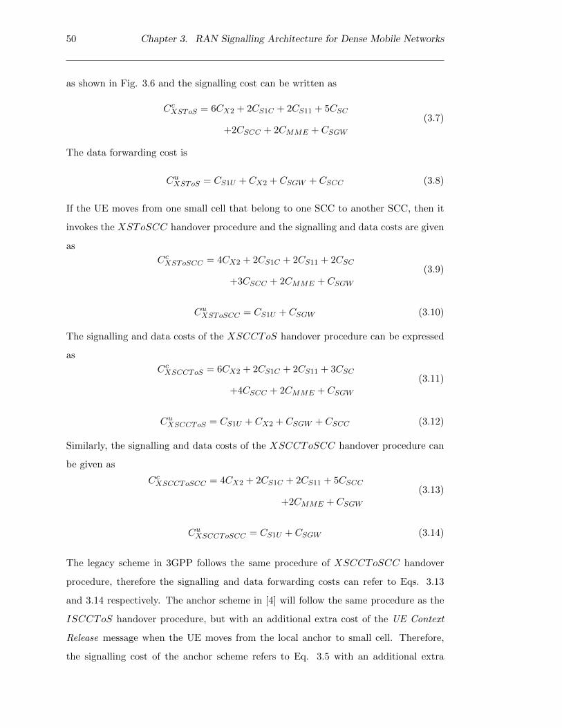
50 Chapter 3. RAN Signalling Architecture for Dense Mobile Networks
as shown in Fig. 3.6 and the signalling cost can be written as
CcXSToS = 6CX2 + 2CS1C + 2CS11 + 5CSC
+2CSCC + 2CMME + CSGW
(3.7)
The data forwarding cost is
CuXSToS = CS1U + CX2 + CSGW + CSCC (3.8)
If the UE moves from one small cell that belong to one SCC to another SCC, then it
invokes the XSToSCC handover procedure and the signalling and data costs are given
as
CcXSToSCC = 4CX2 + 2CS1C + 2CS11 + 2CSC
+3CSCC + 2CMME + CSGW
(3.9)
CuXSToSCC = CS1U + CSGW (3.10)
The signalling and data costs of the XSCCToS handover procedure can be expressed
as
CcXSCCToS = 6CX2 + 2CS1C + 2CS11 + 3CSC
+4CSCC + 2CMME + CSGW
(3.11)
CuXSCCToS = CS1U + CX2 + CSGW + CSCC (3.12)
Similarly, the signalling and data costs of the XSCCToSCC handover procedure can
be given as
CcXSCCToSCC = 4CX2 + 2CS1C + 2CS11 + 5CSCC
+2CMME + CSGW
(3.13)
CuXSCCToSCC = CS1U + CSGW (3.14)
The legacy scheme in 3GPP follows the same procedure of XSCCToSCC handover
procedure, therefore the signalling and data forwarding costs can refer to Eqs. 3.13
and 3.14 respectively. The anchor scheme in [4] will follow the same procedure as the
ISCCToS handover procedure, but with an additional extra cost of the UE Context
Release message when the UE moves from the local anchor to small cell. Therefore,
the signalling cost of the anchor scheme refers to Eq. 3.5 with an additional extra

3.4. Mobility Performance Metrics 51
cost of the UE Context Release message and the data forwarding cost in Eq. 3.6. In
addition, if the UE moves from one small cell to another small cell within a same local
anchor area, then the signalling and data forwarding costs can refer to Eqs. 3.1 and
3.2 respectively. Specifically, if the UE reaches the path switch threshold, then the
anchor scheme in [4] refers to Eqs. 3.13 and 3.14 even though the UE moves within a
same local anchor area. In all other cases, if the UE moves outside of the local anchor
area, then the signalling and data forwarding costs can refer to Eqs. 3.13 and 3.14
respectively.
3.4.2 Signalling Load
The signalling load defines the total number of handover related signalling messages
(sending and receiving) that need to be processed at the node.
3.4.2.1 Signalling Load at the MME
The four signalling messages that need to be processed at the MME during the entire
handover process is:
1. Path Switch Request
2. Path Switch Request Acknowledgment
3. Modify Bearer Request
4. Modify Bearer Response
The path switch signalling messages are exchanged to the MME during inter SCC han-
dover procedure only as described in section 3.3.2. Therefore, the number of signalling
messages processed at the MME can be expressed as
C ldMME = 4 ∗ µuser ∗N (3.15)
where, µuser indicates the average number of UEs in a cluster and N indicates the
number of clusters in small cell network. In case of intra SCC handover procedure, the

52 Chapter 3. RAN Signalling Architecture for Dense Mobile Networks
number of signalling messages processed at the MME is zero as it is easily
discernible from Figs. 3.2, 3.3 and 3.4.
The path switch signalling messages are exchanged to the MME for every UE handover
in the legacy scheme in 3GPP as illustrated in Fig. 2.3. Therefore, Eq. 3.15 is used
to calculate the MME load in the network. Similarly, the same Eq. 3.15 is used in the
anchor scheme in [4] when the UE moves outside of the local anchor area. Besides, the
same Eq. 3.15 will be used in the anchor scheme in [4] when the UE reaches the path
switch threshold even though the UE moves within a same local anchor area.
3.4.2.2 Signalling Load at the SCC
The SCC signalling load defines the number of signalling messages that need to be
processed at the SCC during the entire handover process. These signalling messages
are the Handover Request, Handover Request Acknowledgment, SN Status Transfer,
Path Switch Request, Path Switch Request Acknowledgment and UE Context Release
Command. The number of signalling messages processed at the SCC for the ISToS
handover procedure can be expressed as
C ldISToS = 2 ∗ µuser ∗N (3.16)
The SCC load of the ISToSCC handover procedure is given by
C ldISToSCC = 4 ∗ µuser ∗N (3.17)
The SCC load of the ISCCToS handover procedure is given as
C ldISCCToS = 3 ∗ µuser ∗N (3.18)
The SCC load of the XSToS handover procedure can be written as
C ldXSToS = 4 ∗ µuser ∗N (3.19)
The SCC load of the XSToSCC handover procedure is given as
C ldXSToSCC = 6 ∗ µuser ∗N (3.20)

3.5. Performance Analysis 53
The SCC load of the XSCCToS handover procedure can be expressed as
C ldXSCCToS = 8 ∗ µuser ∗N (3.21)
The SCC load of the XSCCToSCC handover procedure is given as
C ldXSCCToSCC = 10 ∗ µuser ∗N (3.22)
3.5 Performance Analysis
The network modelling framework has been implemented in ns3 [81]. For the network
model level the system is designed to follow the 3GPP EPS topology and build up a
network scenario which consists of one MME, one SGW and up to 100 small cells. All
the nodes are distributed in a geographical area of 1 km2. All neighbour small cells are
interconnected via X2 interfaces [25]. The simulation were performed for a number of
average constant velocities. These were 2 km/h, 4 km/h, 6 km/h, 8 km/h, 10 km/h,
12 km/h and 14 km/h [22], with UE movements based on the random walk mobility
model [82, 83, 84, 85]. The UEs were uniformly distributed and the user density in
the given area was 300 users/km2. The network model configures the path switch
threshold value of two in order to compare with the anchor scheme in [4]. Further,
the network model assumed that all UEs are always in ECM CONNECTED state,
and that all handovers were X2 based. The ns3 based simulator is used to evaluate
the accuracy of the signalling load. It focuses on modelling the mobility management
related control plane for evaluating how the signalling load can deteriorate the overall
performance, and how this is compensated by the introduction of SCCs. There are two
performance evaluation scenarios that are identified in order to analyse the effects of
X2 based handover signalling load in the small cell network these are Cell size and User
velocity scenarios. For simplicity, the SCC at the edge of the cluster is modelled and
the simulation results are discussed in cell size and user velocity scenarios.

54 Chapter 3. RAN Signalling Architecture for Dense Mobile Networks
Table 3.1: Simulation Main Parameters [4, 14, 86]
Parameter Value
Cell Layout hexagonal
Site Height 10 m
UE Height 1 m
Carrier Frequency 2.12 GHz
Mobility Model Random walk mobility model
Path Loss ITU-R P.1411 LOS Propagation Loss model
Transmission Power 20-30 dbm
Antenna Model Parabolic Antenna Model
Site Noise Figure 5 dB
UE Noise Figure 7 dB
Bandwidth 5 MHz
Handover Hysteresis 3 dB
Handover Time to Trigger 256 ms
Handover Algorithm A3-RSRP
Scheduler Type RrFf MAC Scheduler
Beamwidth 70 degrees
Max Attenuation 20 dB
Traffic Model Constant bit rate traffic using UDP, Packet size: 1KB, 1 Packet/ms
Geographical Area 1 km2
Average User Velocity 2-14 km/h
Average User Density 300 users/km2
Cell Size 100-600 m
Cluster Size 7
User movement (0, 2π)
Simulation time 60 seconds

3.5. Performance Analysis 55
Table 3.2: Cost Parameters [4, 14, 86]
Parameter Value
CSC 1ms
CSCC 3ms
CMME 5ms
CSGW 5ms
CX2 1ms
CS1C 2ms
CS1U 1ms
CS11 1ms
The main simulation parameters are defined and listed in Table 3.1. The transmission
latency and the processing latency related parameter values are based on [4, 14, 86]
and listed in Table 3.2.
• Cell Size Scenario: Both average user velocity and user density are constant
and only the cell size changes;
• User Velocity Scenario: Both cell size and average user density are constant
and only the average user velocity changes.
3.5.1 Signalling Load at the CN
In the cell size scenario, the network simulation uses an average velocity of 10 km/h,
user density is 300 users/km2 and cell size shrinks from 600 m to 100 m. The MME
signalling load calculation is based on section 3.4.2.1. The anchor scheme in [4] has
been implemented in ns3 using C++ language. Compared to the legacy scheme in
3GPP, the number of signalling messages processed at the MME is reduced by up to
58.11% on the CN when the cell size shrinks from 300 to 100 m as shown in Fig. 3.13.
As stated earlier, each SCC cluster has six small cells and therefore, seven small cells in
the cluster that includes the SCC small cell as well. With this in mind, it can be seen

56 Chapter 3. RAN Signalling Architecture for Dense Mobile Networks
from Fig 3.13 that the number of SCC cluster increases (from 2 to 15 clusters) when
the cell size shrinks from 300 to 100 m. For example, 15 clusters are needed for 100 m
cell size. Furthermore, the number of cluster remains same when the cell size shrinks
from 600 to 400 m and the number of signalling messages processed at the MME is
reduced by up to 100% in the CN when compared with the legacy scheme in 3GPP.
In addition, the proposed SCC scheme reduces more signalling load at the MME when
compared with the anchor scheme in [4]. Therefore, the proposed SCC significantly
100 200 300 400 500 6000
500
1000
1500
2000
Cell size (m)
Num
ber
of p
roce
ssed
mes
sage
s/m
in
SCC simLegacy simAnchor sim [4]
The number of cluster reduces down to one
Figure 3.13: Effect of cell size: Total handover signalling load at the MME
reduces the CN signalling load in the cell size scenario. Specifically, the path switch
signalling messages on the CN are reduced, this reduction is mainly in the case of X2
based intra SCC handovers.
In the user velocity scenario, the network simulation uses a cell size of 100 m, the
user density is 300 users/km2 and the average user velocity varies from 2 km/h to
14 km/h [22]. As stated earlier, the cell size is constant in the network simulation,
and therefore the number of clusters is fixed. Fig. 3.14 illustrates that the number of
signalling messages processed at the MME increases when the user velocity increases.
Particularly, the number of signalling messages processed at the MME reduces by up to

3.5. Performance Analysis 57
2 4 6 8 10 12 140
500
1000
1500
2000
2500
Average User Velocity (km/h)
Num
ber
of p
roce
ssed
mes
sage
s/m
in
SCC simLegacy simAnchor sim [4]
Figure 3.14: Effect of user velocity: Total handover signalling load at the MME (The
number of clusters is fixed)
41.83% on the CN when compared against the legacy scheme in Fig. 3.14. Moreover, the
proposed SCC reduces the number of signalling messages processed at the MME when
compared against the anchor scheme in [4]. Therefore, the proposed SCC significantly
reduces the CN signalling load in the user velocity scenario. Similar to the cell size
scenario, the path switch signalling on the CN is reduced in the user velocity scenario
as well and this reduction is mainly in the case of X2 based intra SCC handovers.
3.5.2 Signalling and Data Delivery Latency per UE
This section evaluates the signalling latency and the data delivery latency during han-
dover. The latency is calculated based on the transmission latency and the processing
latency of the messages and the calculation is based on section 3.4.1. Fig. 3.15 illus-
trates the ratio of the signalling cost of the proposed scheme to the signalling cost of
the legacy scheme in 3GPP, and this often known as relative signalling delay. Further,
it shows the signalling latency as a function of cell size and it can be seen that more
signalling savings can be achieved when compared against the legacy scheme in 3GPP.

58 Chapter 3. RAN Signalling Architecture for Dense Mobile Networks
1.08
1.1
1.12
1.14
1.16
1.18
1.2
1.22
1.24
1.26
0
0.1
0.2
0.3
0.4
0.5
0.6
100 200 300 400 500
Rel
ativ
e dat
a d
elay
Rel
ativ
e si
gn
alli
ng
del
ay
Cell size(m)
SCC sim-Sig
SCC sim-Data
Signalling cost savings decreases
when the cell size increases
Additional data cost expenditure
decreases when the cell size increases
Figure 3.15: Effect of cell size: Signalling and data delivery latency per UE
However the signalling latency savings come at the expense of increased data delivery
latency, as shown in Fig. 3.15. With the decrease of cell size, the proposed scheme will
incur more data delivery latency than the legacy scheme in 3GPP, because the local
X2 traffic forwarding between the SCC and small cell incurs additional latency. How-
ever, it is commonly accepted that backhaul latency will be higher than the local X2
forwarding latency [14], so the proposed scheme only introduces marginal extra latency
in the user plane data transmission. More importantly, the crossover point denotes a
cell size of 200 m would be balance point between the relative signalling delay and the
relative data delay. Further, it clearly shows that 40% savings of the signalling delay
in handover and an additional 18% of the data delay are the optimal operating points.
This is because when the cell size increases from 100 m to 200 m (i.e. optimal number
of clusters decreases from 15 to 4), less inter SCC based handovers and more intra SCC
based handovers and therefore, optimal cell size is needed to keep the signalling delay
and the data delay at low levels.
Fig. 3.16 shows the signalling latency as a function of user velocity. Similar to the
cell size scenario, it is easily discernible that more signalling savings can be achieved
when compared against the legacy scheme in 3GPP. Further, the proposed SCC scheme
incurs additional data latency when compared against the legacy scheme in 3GPP and
the anchor scheme in [4]. As stated earlier, this additional data latency is due to the

3.5. Performance Analysis 59
1.08
1.1
1.12
1.14
1.16
1.18
1.2
1.22
1.24
1.26
0
0.05
0.1
0.15
0.2
0.25
0.3
0.35
0.4
0.45
2 4 6 8 10
Rel
ativ
e d
ata
del
ay
Rel
ativ
e si
gn
alli
ng
del
ay
Average User Velocity (km/h)
SCC sim-Sig
SCC sim-Data
Signalling cost savings increases
when the user velocity increases
Additional data cost expenditure increases
when the user veloctiy increases
Figure 3.16: Effect of user velocity: Signalling and data delivery latency per UE
X2 forwarding from the SCC to small cell. Specifically, the crossover point denotes a
average user velocity of 4 km/h would be balance point between the relative signalling
delay and the data delay. It shows that 30% savings of the signalling delay in handover
and an additional 18% of the data delay are the optimal operating points. This is due
to the fact that the UE movements between small cells increases as the average user
velocity increases from 2 km/h to 4 km/h that led to frequent path switch operations
at the CN.
3.5.3 Impact of the SCC Mobility Schemes on Handover Performance
The intra-handover from the proposed scheme is illustrated in Fig. 3.17. The bars
illustrate the level of contribution of each type of intra-handover signalling load in the
CN. Similarly, the contributions for inter handovers are shown in Fig. 3.18. Fig. 3.17
illustrates that the IntraSToS handovers consume a greater percentage of signalling
load than other types when the cell size shrinks from 600 m to 100 m. As seen in Fig.
3.18 the InterSToS handovers consume more percentage of CN signalling load than
other types when the cell size shrinks from 300 m to 100 m. The number of clusters
reduces down to one when the cell size shrinks from 600 to 400 m and as a result the
inter handover CN signalling load is zero as shown in Fig. 3.18.
The handover types for each of the proposed schemes are shown in Fig. 3.19 and 3.20.

60 Chapter 3. RAN Signalling Architecture for Dense Mobile Networks
0.00%
10.00%
20.00%
30.00%
40.00%
50.00%
60.00%
70.00%
80.00%
90.00%
100.00%
100 200 300 400 500 600
To
tal
han
do
ver
sig
nal
lin
g
Lo
ad a
t th
e C
N
Cell size (m)
IntraSToS
IntraSToSCC
IntraSCCToS
Figure 3.17: Effect of cell size: Total percentage of intra SCC based handover signalling
load at the CN
0.00%
10.00%
20.00%
30.00%
40.00%
50.00%
60.00%
70.00%
80.00%
90.00%
100.00%
100 200 300 400 500 600
To
tal
han
do
ver
sig
nal
lin
g
Lo
ad a
t th
e C
N
Cell size (m)
InterSCCToSCC
InterSToSCC
InterSToS
InterSCCToS
The number of cluster reduces
down to one
Figure 3.18: Effect of cell size: Total percentage of inter SCC based handover signalling
load at the CN
These illustrate the level of contribution of intra and inter handover signalling load
respectively. It can be seen from Fig. 3.19 that the IntraSToS handovers consume a
greater percentage of signalling load than other types when the user velocity increases
from 2 km/h to 14 km/h. Fig. 3.20 illustrates that the InterSToS handovers consume a
greater percentage of signalling load than other types when the user velocity increases
from 2 km/h to 14 km/h.

3.5. Performance Analysis 61
0.00%
10.00%
20.00%
30.00%
40.00%
50.00%
60.00%
70.00%
80.00%
90.00%
100.00%
2 4 6 8 10 12 14
Tota
l han
dover
sig
nal
ling
Load
at
the
CN
User Velocity (km/hr)
IntraSToS IntraSToSCC IntraSCCToS
Figure 3.19: Effect of user velocity: Total percentage of intra SCC based handover
signalling load at the CN
0.00%
10.00%
20.00%
30.00%
40.00%
50.00%
60.00%
70.00%
80.00%
90.00%
100.00%
2 4 6 8 10 12 14
Tota
l han
dover
sig
nal
ling
Load
at
the
CN
User Velocity (km/hr)
InterSCCToSCC InterSToSCC
InterSToS InterSCCToS
Figure 3.20: Effect of user velocity: Total percentage of inter SCC based handover
signalling load at the CN
3.5.4 Performance Analysis of the Signalling Load Reduction at the
CN
It can be seen from Fig. 3.21 that the number of cluster increases when the cell size
shrinks from 300 to 100 m and the signalling load is reduced by up to 58.11% on the CN.
The number of clusters remain same when the cell size shrinks from 600 to 400 m and
the signalling load is reduced by up to 100% in the CN. Particularly, the crossover point
denotes a cell size of 200 m would be balance point between the signalling reduction

62 Chapter 3. RAN Signalling Architecture for Dense Mobile Networks
in handover at the CN and the number of clusters. Further, it clearly shows that 40%
of the signalling load reduction in handover and six clusters are the optimal operating
points. As stated earlier, this is due to less inter SCC based handovers and more intra
SCC based handovers.
0
2
4
6
8
10
12
14
16
0.00%
10.00%
20.00%
30.00%
40.00%
50.00%
60.00%
70.00%
80.00%
90.00%
100.00%
100 200 300 400 500 600
Num
ber
of
clust
ers
Tota
l han
dover
sig
nal
ling
load
re
du
ctio
n a
t th
e C
N
Cell size (m)
Signalling load
Number of clusters
Figure 3.21: Effect of cell size: Total percentage of reduction in handover signalling
load at the CN
0
2
4
6
8
10
12
14
16
0.00%
5.00%
10.00%
15.00%
20.00%
25.00%
30.00%
35.00%
40.00%
45.00%
2 4 6 8 10 12 14
Num
ber
of
clust
ers
Tota
l han
dover
sig
nal
ling
load
re
duct
ion a
t th
e C
N
User Velocity (km/hr)
Signalling load
Number of clusters
Figure 3.22: Effect of user velocity: Total percentage of reduction in handover signalling
load at the CN (The number of clusters is fixed)
The signalling load reduces by up to 41.83% on the CN when compared against the
legacy scheme in Fig. 3.22. Besides, the average user velocity of 2km/h would be

3.6. Summary 63
crossover point between the signalling load reduction in handover at the CN and the
number of clusters. It is easily discernible that 40% of the signalling load reduction in
handover on the CN and fourteen clusters are the optimal operating points. This is
because the UE most likely to perform path switch operations at the CN. Specifically,
the number of clusters is remaining same in the user velocity scenario. Therefore, the
proposed SCC significantly reduces the signalling load on the CN in both cell size and
user velocity scenarios.
3.6 Summary
Small cells are becoming a promising solution for providing enhanced coverage and
maximizing system capacity in a large-scale environment. In such a network, the large
number of small cells may cause mobility signalling overload on the CN due to frequent
handovers. Nonetheless, the signalling overload incurred by path switch operations on
the CN can be reduced by a new signalling architecture. In the new architecture, small
cells are formed in to clusters and within a cluster, a designated SCC controls and
manages the group of small cells and maintains associated forwarding information for
UEs within a localized mobility management domain. Further, cluster based mobility
management schemes are proposed in the new signalling architecture. Compared to
the legacy scheme in 3GPP, the simulation results show that the proposed signalling
architecture achieves the signalling reduction gain by up to 58.1% on the CN with
various cell sizes. In addition, it is able to reduce the signalling gain by up to 41.8% on
the CN with various user velocities. In fact, the proposed signalling architecture saves
more signalling load and signalling latency when compared against the anchor scheme
in [4].
Therefore, from operational reduction (reducing a number of direct S1 connections to
the CN), better scalability (reducing a number of S1 bearers on the CN) and reduction
of signalling load on the CN perspective, the proposed signalling architecture is a viable
and preferable option for dense small cell networks. Given that small cell networks are
still at an early stage of deployment, a small upgrade is only required in the RAN side,
that means an incremental upgrade is required in small cells.

64 Chapter 3. RAN Signalling Architecture for Dense Mobile Networks

Chapter 4
A Clustering Optimisation
Approach in Dense Mobile
Networks
4.1 Introduction
Based on the signalling architecture described in Chapter 3, this chapter further consid-
ers how to select the SCC according to the anticipated UE distribution in the given area.
The growth in number of small cells in the large-scale environment is primarily due to
enhanced coverage and increasing system capacity. In such an environment, multiple
SCCs are needed in a scalable manner in order to cope with high volume of handover
signalling load and also data volume demand due to the UE mobility across small cell
boundaries. The selection of the SCC plays a crucial role in the overall performance of
radio access networks in order to minimize the CN signalling load introduced by UE
mobility. Especially in a clustering based approach, one of the main concerns is the
selection of the appropriate SCCs in the network and the formation of balanced clusters
in terms of traffic load in a highly user density environment. System parameters like
the number of small cells in the network and required number of the SCCs need to be
taken into consideration. With this is mind, the SCCs are selected first based on user
density profile and then cluster formation takes place. This approach not only aims to
65

66 Chapter 4. A Clustering Optimisation Approach in Dense Mobile Networks
reduce signalling load on the CN but also to balance the traffic load on the SCCs in
terms of number of users. Therefore, this approach proposes an algorithm which aims
to evenly distribute all small cells to form well balanced clusters in highly dense small
cell networks. In this context, the proposed algorithm aims to
• Select an optimal SCC according to the anticipated UE distribution in the given
area in order to reduce the signalling load on the CN introduced by UE mobility.
• Evenly distribute small cells to the various SCC clusters formed, hence resulting
in a well distributed set of small cells.
The detailed information about the algorithm will be discussed in next section 4.2.
4.2 A Scalable Clustering based Approach for the SCC
This section presents the scalable clustering based approach for the SCC in small cell
networks. This approach proposes the clustering optimisation algorithm. In this algo-
rithm, it is assumed that every small cell must belong to one SCC. There are two input
data sets i.e. the SCC configuration and the user density profile. The SCC configura-
tion contains the list of small cells, required number of the SCCs and maximum radius.
The user density profile contains the list of small cells with the number of UEs that
previously connected to them. The input data sets are preconfigured by the mobile
network operator in order to run the algorithm and the results that are used to plan
the SCC clusters in dense small cell networks. As stated earlier, the selection of the
optimal SCC is based on the UE distribution in the given area in order to reduce the
signalling load on the CN introduced by the UE mobility, therefore the user density
should be considered in the SCC selection process.

4.2. A Scalable Clustering based Approach for the SCC 67
4.2.1 The Clustering Optimisation Algorithm
Algorithm 1 The Clustering Optimisation Algorithm
Input: SCC configuration (Network data- The list of small cells, M- The number of
SCCs, Maximum radius) and user density profile
Output: SCCClusterList
Initialisation: Empty the SCCClusterList
1: Select top M SCCs with regards to the user density from user density profile and
store them in to the SCCList.
2: Set SmallCelllList = NetworkData
3: Remove M SCCs from the SmallCellList
4: Categorised each non-SCC small cells according to the following list:
1. DirectNbrList
2. CommonDirectNbrList
3. RemoteNbrList
4. CommonRemoteNbrList
5: Add DirectNbrList into SCCClusterList
6: Add RemoteNbrList into SCCClusterList
7: Set templist = ComputeSCCForCommonNbrCells (SC-
CList,CommonDirectNbrList,MaxRadius)
8: Add templist into SCCClusterList
9: Set templist = ComputeSCCForCommonNbrCells (SC-
CList,CommonRemoteNbrList,MaxRadius)
10: Add templist into SCCClusterList
11: return SCCClusterList
The algorithm framework is described in Algorithm 1. Firstly, the SCCClusterList
(output) is initialized with an empty set during the initialization phase and then top
M SCCs is selected with regard to the user density from user density profile and store
them into the SCCList. Here, M , SCCClusterList and SCCList refers to required

68 Chapter 4. A Clustering Optimisation Approach in Dense Mobile Networks
number of the SCCs, a list of the SCC clusters (all small cells that are members of
the SCC clusters) and a list of the SCCs respectively. After completion of the SCCs
selection, each non-SCC small cells is categorised according to the following lists:
1. DirectNbrList: Small cells that are direct neighbours to a SCC
2. CommonDirectNbrList: Small cells that are direct neighbours to more than one
SCCs
3. RemoteNbrList: Small cells that are indirect neighbours to any SCC according
to smaller inter site distance
4. CommonRemoteNbrList: Small cells that are indirect neighbours to more than
one SCCs but with the same inter site distance.
After categorised, DirectNbrList andRemoteNbrList are directly added into SCCClusterList.
For direct neighbours, it is easy to select the SCC and associate with it. Similarly for
remote neighbours, the SCC is selected according to the smallest inter site distance.
But in case of CommonDirectNbrList and CommonRemoteNbrList, the SCC selec-
tion is not very straight forward because all the SCCs have same inter site distance.
The common neighbours algorithm is proposed in order to compute the common neigh-
bours, as shown in Fig. 4.1. By applying this algorithm, both CommonDirectNbrList
and CommonRemoteNbrList are resolved and the result will be added in to the
SCCClusterList.
Fig. 4.1 illustrates the algorithm by using flow chart. This algorithm takes three
inputs, including the list of selected SCCs, the list of non-SCC small cells (common
neighbours) and maximum radius. It traverses a loop, where at each iteration one
SCC cluster is updated and result is added to CommonNbrSCCClusterList. At the
beginning of each iteration, one of the SCCs in SCCList is selected. Starting from this
selected SCC, this algorithm builds the cluster around the selected SCC and returns
the CommonNbrSCCClusterList. For each selected SCC, the number of unassigned
common neighbours is determined in radial enlargement. The way how to choose
the SCC for each common neighbours plays an important role in the quality of this

4.2. A Scalable Clustering based Approach for the SCC 69
Is SCCList empty?
For the selected SCC, determine the number
of unassigned common neighbours from the
CommonNbrList in radial enlargement
For each common neighbour, find the SCC
which has a high number of direct neighbours
to that common neighbour. If more than one
SCC found, then select the SCC which has the
least number of users
1. Add a common neighbour with the SCC
into a CommonNbrSCCClusterList
2.Remove the common neighbour from
CommonNbrList
Any unassigned
common neighbours
found?
Return
CommonNbrS
CCClusterList
Is MaxRadius
Reached?
Yes
Get the first SCC from the SCCList?
No
ComputeSCCForCommonNbrCells()
SCCList,CommonNbrList,MaxRadius
Remove the
SCC from the
SCCList
Yes
No
No
Yes
Radial increment
Figure 4.1: Algorithm 2: Compute Common Neigbhours
algorithm. For simplicity, this algorithm considers that all small cells in this network
are hexagonal, where each small cell has six adjacent small cells. In that case for each
common neighbour from CommonNbrList, find the SCC which has a high number of
direct neighbours that are adjacent to the common neighbour. If more than one SCC
is found, then select the SCC which has the least number of users according to user
density profile. Here, the number of users is accumulated at the SCC cluster level that
includes the SCC and all small cells belonging to that SCC. Furthermore, small cells
that have been assigned to a cluster are removed from CommonNbrList. The loop
continues with the next iteration until all common neighbours have been assigned to

70 Chapter 4. A Clustering Optimisation Approach in Dense Mobile Networks
the SCC cluster.
4.2.2 Example of the Clustering Optimization Algorithm
SCC configuration:
Num. of the SCCs= 3, Small cells=1 to 49 & Max.Radius= 3km
(*) Assume each small cell has 100 m in radius
User density Profile (in terms of number of users):
Small cells 17,22 and 32 = 100 and other small cells = 10
Common
direct
neighbours
Common
remote
neighbours
Direct
neighbours
Remote
neighbours
Controlled
by SCCsSCCs
21
3
54
6
87
9
1110
12
2625
27
2322
24
2019
21
1716
18
1413
15
3837
39
3534
36
3231
33
2928
30
4140
42
4443
45
4746
4849
Figure 4.2: An example of algorithm output scenario 1
An example with two different scenarios is shown in Figs. 4.2 and 4.3. These scenarios
are covering all four types of neighbours. For simplicity, this example considers 49
small cells and three SCCs in both scenarios and also small cells 17, 22 and 23 have
100 users and other small cells have 10 users in the first scenario. The algorithm steps
have illustrated at each stage along with results in the following order:
1. Firstly, the SCCs are selected with regards to high user density: SCCs {17, 22,
23}
2. Secondly, direct neighbours are selected for each SCC: SCC 17:{13, 16, 18, 30},
SCC 22:{11, 23, 24, 26,27,39} and SCC 32:{31,43,45,48}
3. Thirdly, remote neighbours are selected according to inter site distance from each
of them to the nearest SCC: SCC 17:{1, 2, 3, 5, 6, 13, 14, 15, 16, 18, 21, 30},

4.2. A Scalable Clustering based Approach for the SCC 71
SCC 22:{7, 8, 9, 10, 11, 12, 19, 23, 24, 25, 26, 27, 34, 37, 38, 39, 49} and SCC
32:{31, 35, 40, 41, 43, 44, 45, 46, 47, 48}
4. Fourthly, common direct neighbours are selected according to a high number of
assigned direct neighbours from each of them: SCC 17:{1, 2, 3, 5, 6, 13, 14, 15,
16, 18, 21, 30}, SCC 22:{7, 8, 9, 10, 11, 12, 19, 23, 24, 25, 26, 27, 34, 37, 38, 39,
49} and SCC 32:{28, 31, 33, 35, 40, 41, 43, 44, 45, 46, 47, 48}
5. And finally, common remote neighbours are selected according to a high number
of assigned direct neighbours from each of them, but with the same inter site
distance to the SCC: SCC 17:{1, 2, 3, 4, 5, 6, 13, 14, 15, 16, 18, 20, 21, 30}, SCC
22:{7, 8, 9, 10, 11, 12, 19, 23, 24, 25, 26, 27, 34, 36, 37, 38, 39, 49} and SCC
32:{28, 29, 31, 33, 35, 40, 41, 42, 43, 44, 45, 46, 47, 48}
21
3
54
6
87
9
1110
12
2625
27
2322
24
2019
21
1716
18
1413
15
3837
39
3534
36
3231
33
2928
30
4140
42
4443
45
4746
4849
SCC configuration:
Num. of the SCCs= 3, Small cells=1 to 49 & Max.Radius= 3km
(*) Assume each small cell has 100 m in radius
User density Profile (in terms of number of users):
Small cells 20,31 and 36 = 100 and other small cells = 10
Common
direct
neighbours
Common
remote
neighbours
Direct
neighbours
Remote
neighbours
Controlled
by SCCsSCCs
Figure 4.3: An example of algorithm output scenario 2
After execution of the above steps, the result of the algorithm is easily discernible from
Fig. 4.2 that small cells are evenly distributed to the various SCC clusters and hence
obtain a well distributed set of small cells. In the second scenario, small cells 20, 31

72 Chapter 4. A Clustering Optimisation Approach in Dense Mobile Networks
and 36 have 100 users and other small cells have 10 users. Similar to the first scenario,
small cells are evenly distributed to the various SCC clusters and well balanced in the
network. In both scenarios, the clusters that are formed by the proposed algorithm are
well balanced in terms of user density.
4.3 Performance Analysis
This section evaluates the performance of the proposed SCC clustering scheme and
compares it against the legacy scheme in 3GPP and the anchor scheme in [4] through
a system level simulation. The network modelling framework has been implemented
in the network simulator ns3 [81]. This network model considers that each hexagonal
cell area is served by a small cell and all small cells that are distributed within a given
geographical coverage area of 1 km2. For the network model, the system is designed to
follow the 3GPP evolved packet system topology and build up a network scenario which
consists of one MME, one SGW and up to 150 small cells. All neighbour small cells
are interconnected via physical interfaces. The UE movement follows the shortest path
map based movement model [87] with average user velocities of 2-10 km/h. In order
to compare the anchor scheme in [4], the network model configures the path switch
threshold value of two. The shortest-path-map-based movement model provides points
of interest hotspot areas (destination coordinates), speeds and pause times. In addition,
it uses the Dijkstra’s shortest path algorithm to calculate the shortest path from the
current location to the destination. For simplicity, the network model has defined three
hotspot areas in the mobility model with an average inter-hotspot distance of 1 km,
where the UEs are uniformly distributed and the user density in the given area varies
from 100 to 300 users/km2. Besides, the UEs move randomly to selected hot spot
areas during the simulation period. The network model assumed all UEs are always in
ECM CONNECTED state, and that all handovers were X2 based. The main simulation
parameters are defined and listed in Table 3.1.
There are four performance evaluation scenarios that are identified in order to analyse
the effects of mobility management in the network:

4.3. Performance Analysis 73
• Varying the number of SCCs: The number of small cells, average user velocity
and average user density are constant and only the number of SCC changes;
• Varying the number of small cells: The number of SCCs, average user ve-
locity and average user density are constant and only the number of small cells
changes;
• Varying the average user velocity: The number of SCCs, the number of small
cells and average user density are constant and only the average user velocity
changes;
• Varying the average user density: The number of SCCs, the number of small
cells and average user velocity are constant and only the average user density
changes;
4.3.1 Signalling Load at the CN
This chapter first evaluates the impact of the signalling load on the CN in terms of
the number of messages processed at the MME, as the signalling load calculation is
described in section 3.4.2.1. The transmission latency and the processing latency re-
lated parameter values are based on Table 3.2. The network model considers that the
number of small cells ranges from 50 to 150 and they are distributed within the given
geographical area of 1 km2. In this network, 300 UEs are randomly distributed in three
hotspot areas, and they move with average velocity of 10 km/h. Firstly, the clustering
optimisation algorithm is executed and as a result each hotspot area forms a new SCC
cluster in the network. After formation of the SCC clusters, the UEs move randomly
to selected hot spot areas during the simulation period as the mobility performance is
illustrated in Fig. 4.4.
Fig. 4.4 shows the number of signalling messages processed at the MME per minute
as a function of the number of small cells under various user velocities. It is shown
that the proposed SCC scheme can significantly reduce the number of signalling mes-
sages that need to be processed at the MME, even when the average velocity is low (2
km/h). More signalling overhead can be saved at the MME when the average velocity

74 Chapter 4. A Clustering Optimisation Approach in Dense Mobile Networks
50 75 100 125 1500
500
1000
1500
2000
2500
Number of small cells
Num
ber
of p
roce
ssed
mes
sage
s/m
in
SCC sim,Avg.velocity=2SCC sim,Avg.velocity=4SCC sim,Avg.velocity=6SCC sim,Avg.velocity=8SCC sim,Avg.velocity=10Legacy sim,Avg.velocity=10Anchor sim,Avg.velocity=10 [4]
Figure 4.4: Effect of small cells: Total handover signalling load at the MME (The
number of SCCs is fixed)
increases. Furthermore, Fig. 4.4 illustrates that enlargement of the SCC cluster size
(in terms of the number of small cells per SCC) has two simultaneous effects on han-
dover performances. Larger SCC clusters indicate more intra SCC handovers, but this
condition also means less inter SCC handovers. Moreover, the path switch operation
can happen only in case of inter SCC handovers as a result the effect of signalling load
on the MME causes slower grow rate when the number of small cells increases. It is
easily discernible from Fig. 4.4 that more signalling savings can be achieved by the
proposed SCC scheme compared with the legacy scheme and the anchor scheme in [4].
Particularly, the proposed scheme reduces the signalling gain up to 85.48% on the CN
with various number of cells when compared against the legacy scheme in 3GPP.
The impact of the signalling load on the CN is evaluated in the user velocity scenario.
The network model considers that 100 small cells are distributed within the given
geographical area of 1 km2. In this network, 300 UEs are randomly distributed in
three hotspot areas, and they move with different range of user velocities. Similar to

4.3. Performance Analysis 75
2 4 6 8 100
200
400
600
800
1000
1200
1400
1600
Average User Velocity (km/h)
Num
ber
of p
roce
ssed
mes
sage
s/m
in
SCC sim,Num of SCCs=1SCC sim,Num of SCCs=2SCC sim,Num of SCCs=3Legacy simAnchor sim [4]
Figure 4.5: Effect of user velocity: Total handover signalling load at the MME
the previous scenario, firstly the clustering optimisation algorithm is executed with the
number of SCC ranges from 1 to 3 and then UEs move randomly to selected hotspot
areas and the results are shown in Fig. 4.5. It illustrates the number of signalling
messages processed at the MME per minute as a function of the average user velocity
under the number of SCCs. According to Fig. 4.5, fast moving users increase signalling
load on the CN as a result of the higher number of handovers. More signalling savings
can be achieved by the proposed SCC scheme compared with the legacy scheme and the
anchor scheme in [4]. In addition, Fig. 4.5 illustrates that all three hotspot areas are
controlled by the SCCs to range from one to three (shrinkage of the SCC cluster size)
have two simultaneous effects on handover performance. Smaller clusters can indicate
more inter SCC handovers, but this condition also means less intra SCC handovers and
as a result the effect of signalling load on the MME causes slower grow rate in overall
metrics. Compared to the legacy scheme in 3GPP, the proposed SCC scheme reduces
the signalling gain up to 82.9% on the CN with the number of SCCs is three.
In the user density scenario, the network model considers that 100 small cells are

76 Chapter 4. A Clustering Optimisation Approach in Dense Mobile Networks
100 150 200 250 3000
200
400
600
800
1000
1200
1400
1600
Average User Density (users/km2)
Num
ber
of p
roce
ssed
mes
sage
s/m
in
SCC sim,Num of SCCs=1SCC sim,Num of SCCs=2SCC sim,Num of SCCs=3Legacy simAnchor sim [4]
Figure 4.6: Effect of user density: Total handover signalling load at the MME
distributed within the given geographical area of 1 km2 and all UEs move with average
velocity of 10 km/h. In this network, various user densities are randomly distributed
in three hotspot areas and the clustering optimisation algorithm is executed with the
number of SCC ranging from 1 to 3. Fig. 4.6 shows the number of signalling messages
processed at the MME per minute as a function of the average user density under
the number of SCCs. It is easily discernible from Fig. 4.6 that the proposed SCC
scheme can significantly reduce the number of signalling messages processed at the
MME, even when the user density is low (100 users), and therefore, similar to the user
velocity scenario, more signalling load savings can be achieved in the proposed SCC
scheme compared with the legacy scheme and the anchor scheme in [4]. Moreover,
more signalling load can be saved when there is a single SCC because all small cells
are controlled by its SCC, and hence only intra SCC handover is possible and as a
result all path switch signalling messages are not forwarded to the CN by the SCC.
Specifically, the proposed SCC scheme reduces the signalling gain up to 82.9% on the
CN with the number of SCCs is three when compared against the legacy scheme in

4.3. Performance Analysis 77
3GPP. It is clearly shown that the proposed SCC scheme can significantly reduce the
signalling load on the CN in all scenarios.
4.3.2 Signalling and Data Delivery Latency per UE
1.1
1.12
1.14
1.16
1.18
1.2
1.22
0
0.05
0.1
0.15
0.2
0.25
0.3
50 75 100 125 150
Rel
ativ
e dat
a del
ay
Rel
ativ
e si
gn
alli
ng
del
ay
Number of small cells
SCC sim-Sig,Avg.velocity=10
SCC sim-Data,Avg.velocity=10
Signalling cost savings increases when the
Additional data cost expenditure increases when
the number of small cells increases
Figure 4.7: Effect of the number of small cells: Signalling and data delivery latency
per UE
This section evaluates the signalling and data forwarding cost during the entire han-
dover as the cost calculation is described in section 3.4.1. The relative signalling delay
and the relative data delay are used for better illustration in Figs. 4.7 and 4.8, it is
defined as the ratio of the cost of the proposed scheme to the cost of the legacy scheme
in 3GPP under the same parameter setting. For comparison, the same simulation envi-
ronment as described in section 4.3.1 is used. Fig. 4.7 illustrates the relative cost ratio
between the proposed scheme and the legacy scheme as a function of the number of
small cells under various user velocities. It shows that more signalling savings can be
achieved when the SCC cluster size increases (in terms of the number of small cells per
SCC increases). This is because the UE movement within a SCC cluster is more likely
to perform path switch operation on the CN. Furthermore, the signalling cost of the
proposed SCC scheme increases when the user velocity increases. More importantly,
the crossover point denotes 75 small cells would be balance point between the relative

78 Chapter 4. A Clustering Optimisation Approach in Dense Mobile Networks
signalling delay and the relative data delay. Further it shows that 20% savings of the
signalling delay in handover and an additional 18% of the data delay are the optimal
points. This is due to the fact that less inter SCC based handovers and more intra SCC
based handovers are possible at the optimal point.
Fig. 4.8 shows the relative cost ratio between the proposed scheme, the anchor scheme
in [4] and the legacy scheme as a function of the average user velocity under the number
of SCCs. It shows that the signalling cost of the proposed SCC scheme increases when
the number of SCCs increases (in terms of the number of small cells per SCC decreases).
Besides, the signalling cost of the proposed SCC scheme increases when the user velocity
increases, because the UE crosses the SCC cluster boundaries more frequently. It can be
easily seen from Fig. 4.8 that more signalling savings can be achieved when compared
with the legacy scheme in 3GPP. Specifically, the crossover point denotes the average
user velocity of 4 km/h would be balance point between the relative signalling delay
and the relative data delay. It clearly shows that 40% savings of the signalling delay in
handover and an additional 13% of the data delay are the optimal points.
0.95
1
1.05
1.1
1.15
1.2
1.25
0
0.1
0.2
0.3
0.4
0.5
0.6
2 4 6 8 10
Rel
ativ
e d
ata
del
ay
Rel
ativ
e si
gn
alli
ng
del
ay
Average User Velocity (km/h)
SCC sim-Sig,Num of SCCs=1 SCC sim-Sig,Num of SCCs=2
SCC sim-Sig,Num of SCCs=3 SCC sim-Data,Num of SCCs=1
SCC sim-Data,Num of SCCs=2 SCC sim-Data,Num of SCCs=3
Additional data cost expenditure increases
when the user velocity increases Signalling cost savings increases when
the user velocity increases
Figure 4.8: Effect of user velocity and the number of SCCs: Signalling and data delivery
latency per UE
The signalling cost savings come at expense of the data forwarding cost, as shown in
Figs. 4.7 and 4.8. With the increase of number of small cells and user velocity, the
proposed scheme will incur additional data forwarding latency than the legacy scheme
in 3GPP. This is because the local X2 traffic forwarding between the SCC and the

4.3. Performance Analysis 79
small cell incurs additional latency. However, it is a typical case that the backhaul
latency is higher than the local X2 traffic forwarding latency in small cell networks
[14]; the proposed scheme only introduces marginal extra latency in the user plane
data transmission which may be negligible in most realistic cases. Moreover, the data
cost increases in the proposed scheme when the number of small cells and user velocity
increases. Therefore, the SCC scheme can be selected, based on the signalling and data
forwarding cost requirements.
4.3.3 Signalling load at the SCC
50 75 100 125 1500
200
400
600
800
1000
Number of small cells
Num
ber
of p
roce
ssed
mes
sage
s/m
in
SCC sim,Avg.velocity=2SCC sim,Avg.velocity=4SCC sim,Avg.velocity=6SCC sim,Avg.velocity=8SCC sim,Avg.velocity=10
Figure 4.9: Effect of the number of small cells: Total handover signalling load at the
SCC (The number of SCCs is fixed)
This section evaluates the impact of the signalling load on the SCC side in terms of
the number of messages processed at the SCC and signalling load calculation of the
SCC is described in section 3.4.2.2. Although this work do not explicitly model the
SCC overload at the RAN-side that could results from large processing requests from
small cells, the SCC signalling load can somewhat reflect this overload condition. For

80 Chapter 4. A Clustering Optimisation Approach in Dense Mobile Networks
comparison, the same simulation environment as described in previous section 4.3.1 is
used. Fig. 4.9 shows that the number of signalling messages processed at the SCC
increases when the number of small cells and the average user velocity increases. As
stated earlier, the number of intra SCC handover increases when the number of small
cells increases in the SCC cluster (enlargement of SCC cluster size) and as a result Fig.
4.9 shows that the combined effect of intra and inter SCC signalling load on the SCC
causes higher grow rate when the number of small cells increases.
0.00%
10.00%
20.00%
30.00%
40.00%
50.00%
60.00%
70.00%
80.00%
90.00%
100.00%
2 4 6 8 10
Tota
l han
dov
er s
ign
alli
ng
load
red
uct
ion a
t th
e S
CC
Average User Velocity (km/h)
SCC Sim, Num of SCCs=2
SCC Sim, Num of SCCs=3
Figure 4.10: Effect of user velocity: Total percentage of reduction in handover signalling
load at the SCC in comparison with single SCC
It can be directly inferred that the number of signalling messages processed at the SCC
increases when the user velocity increases, as shown in Fig. 4.10. As stated earlier, the
number of inter SCC handover increases when the number of SCCs increases (shrinkage
of SCC cluster size), in which case the combined effect of intra and inter SCC signalling
load causes higher grow rate on the SCC.
Similar to the user velocity case, the signalling messages on the SCC increases when
the number of SCCs and the average user density increases, as shown in Fig. 4.11. It
can be further inferred that the number of signalling messages on the SCC is high when
the number of SCCs is one, because all small cells that are controlled and managed by
the single SCC. By increasing the number of SCCs, the signalling load will be balanced
on the SCCs. Conversely, with the decrease of the number of SCCs, more signalling
load can be achieved on the CN. Thus, the number of SCCs can be selected according

4.4. Summary 81
0.00%
10.00%
20.00%
30.00%
40.00%
50.00%
60.00%
70.00%
80.00%
90.00%
100.00%
100 150 200 250 300
To
tal
han
do
ver
sig
nal
lin
g l
oad
red
uct
ion
at
the
SC
C
Average User Density (users/km2)
SCC Sim, Num of SCCs=2 SCC Sim, Num of SCCs=3
Figure 4.11: Effect of user density: Total percentage of reduction in handover signalling
load at the SCC in comparison with single SCC
to the UE distribution in the given area. Therefore, the proposed SCC scheme can be
selected based on the number of small cells and the number of SCCs requirements.
4.4 Summary
In large-scale small cell networks, an increase number of UEs can augment the signalling
load on the CN due to user mobility. In order to achieve effective signalling reduction on
the CN, the previous chapter 3 introduced a new signalling architecture with clustered
small cells supported by an entity called SCC. This chapter further extends the previous
work by selecting optimised locations of SCCs and how conventional small cells are
clustered around them. As such an environment, this chapter introduces the clustering
optimisation algorithm. From a scalability perspective, this algorithm is designed to
select multiple optimal SCCs due to the growth in number of small cells in the large-
scale environment. Specifically, this algorithm is designed to balance the traffic load
on the SCC by selecting the SCCs first and then forming the well distributed cluster of
small cells. Furthermore, this chapter describes two example scenarios for the proposed
algorithm. It is evaluated through the realistic system level simulation and results show
that significant signalling overhead savings can be achieved and more signalling cost
can be saved when compared against the legacy scheme in 3GPP and the anchor scheme
in [4]. Particularly, the proposed scheme reduces the signalling gain up to 85.48% on

82 Chapter 4. A Clustering Optimisation Approach in Dense Mobile Networks
the CN with various number of cells and it reduces the signalling gain up to 82.9% on
the CN with the number of SCCs is three in both the user velocity and user density
scenarios.
Therefore, based on the number of small cells and cost requirements, the proposed
algorithm can be selected. For the optimal SCC selection, well balanced cluster forma-
tion and signalling load reduction on the CN perspective, the proposed algorithm is a
viable and preferable option for small cell networks especially in a highly user density
environment.

Chapter 5
A Scalable Architecture for
Handling Control Plane Failures
in Heterogeneous Networks
5.1 Introduction
This chapter applies the proposed SCC scheme in Chapter 3 for tackling the loss of
control plane failures of small cells due to macro cell failure in heterogeneous networks.
The proposed SCC scheme that takes the control of small cells in a clustered fashion
during the macro cell fail-over period. By default a cluster is the set of small cells
covered under the common macro cell. Specifically, upon the failure of the umbrella
macro cell, a pre-determined small cell in each cluster can become an autonomous
local SCC for handling control plane functions (in particular UE mobility handover
signalling) as a bridge between the rest of the affected small cells and the CN. In that
way, unnecessary handover signalling to the CN incurred by UEs frequent mobility
can still be avoided, and similar behaviour as before in heterogeneous networks is
still maintained. Moreover, the SCC maintains a cluster of small cells and associated
forwarding information for UEs within a localized mobility management domain.
83

84 Chapter 5. A Scalable Architecture for Handling Control Plane Failures in
Heterogeneous Networks
5.2 A Macro cell goes down in Heterogeneous Networks
This section first introduces the protection scenario upon macro cell failures according
to the legacy architecture. Then, it presents the proposed SCC architecture for tackling
the loss of control plane functions due to macro cell failures, in order to avoid heavy
UE handover signalling that the legacy scheme suffers from. In this chapter, the SGW
refers to both SGW and PGW network elements. The detailed descriptions of each
functional entity can be found in [15].
5.2.1 The Legacy Procedure
This section discuss about the macro cell failure handling scenario, which is impacted
by equipment failure, power outage etc. in heterogeneous network [7], and necessary
techniques should be in place in order to enable small cells to work autonomously upon
the failure of the macro cell, as shown in Fig. 5.1. It can be seen from Fig. 5.1a and
5.1b that the UE connectivity procedure steps are numbered in the following order:
1. An UE sends an attach request message to the macro cell/small cell4 in the control
plane
2. The macro cell/small cell4 forwards an attach request message to the MME
3. After successful connection establishment with the CN, the SGW forwards the
user plane data to small cell4
4. The UE connects to small cell4 in the user plane; small cell4 forwards the user
plane data to the UE
Since small cells radio coverage will reside within an existing macro cell coverage, a UE
attaches to the macro cell in the control plane and to small cell4 in the user plane, as
shown in Fig. 5.1a. The support of control plane signalling with the CN is covered by
the macro cell and the data transmission from/to the SGW in the user plane is fulfilled
by small cell4. In such a scenario, when a macro cell goes down all its macro cell
contexts shall be deleted. All neighbour small cells (small cell1, small cell2, small cell3

5.2. A Macro cell goes down in Heterogeneous Networks 85
Macro cell
A UE connects to the macro cell in the control
plane and to the small cell in the user plane
Small cell 1
Small cell 2
Small cell 3
Small cell 4
Control Plane User Plane
Step (1)
(2)(3)
(4)
EPC
MMESGW/
PGWS5/S11
S1-C/
S1-U
X2
(a) Normal operation without failure
(Legacy scheme)
Small cell 1
Small cell 2
Small cell 3Small cell 4
Macro cell
A UE connects to the small cell in the
control plane and the user plane
Control Plane User Plane
Macro
cell
goes
down
(2)
(4)
(3)
Step (1)
EPC
MMESGW/
PGWS5/S11
X2
S1-C/
S1-U
(b) Post-failure operation (Legecy scheme)
Small cell 1 with SCC
Small cell 2
Small cell 3
Small cell 4
Macro cell
A UE connects to the small cell in the
control plane and the user plane
Macro
cell
goes
down
SCC
becomes
active
(5)(2)
(3)
(6)
(4)
Control Plane User Plane
No control/user plane transmission
Step (1)
EPC
MME SGW/PGWS5/S11
S1-C/
S1-U
X2
(c) Post-failure operation (SCC scheme)
Figure 5.1: A macro cell goes down in the heterogeneous network.

86 Chapter 5. A Scalable Architecture for Handling Control Plane Failures in
Heterogeneous Networks
and small cell4) detect the failure of the macro cell over an X2 interface, where they
shall delete the forwarding tunnel contexts. When the MME detects the unavailability
of the macro cell, it locally deletes the macro cell related contexts and initiates release
of all S1 bearers towards the SGW by sending a ReleaseAccessBearerRequest message
[38]. Furthermore, the MME shall initiate DedicatedBearerDeactivation procedure in
the packet core [88]. Upon receiving the ReleaseAccessBearerRequest message, the
SGW shall release all macro cell related information [38]. Besides, the affected UEs
which were originally attached to the macro cell will be connected to small cell4 in the
control plane and the user plane, as shown in Fig. 5.1b.
5.2.2 The Proposed Procedure
In the legacy scheme, the affected UEs are attached to small cells in the control plane,
which can introduce high mobility signalling load on the CN during the macro cell fail-
over period. This situation will be mitigated by applying the proposed SCC scheme
on small cell1, which takes the local control of small cells (small cell2, small cell3 and
small cell4) in a clustered fashion, as shown in Fig. 5.1c. It can be seen from Fig. 5.1c,
the UE connectivity procedure steps are numbered in the following order:
1. An UE sends an attach request message to small cell4 in the control plane
2. Small cell4 forwards an attach request message to the SCC (small cell1)
3. The SCC (small cell1) forwards an attach request message to the MME
4. After successful connection establishment with the CN, the SGW forwards the
user plane data to the SCC (small cell1)
5. The SCC (small cell1) forwards the user plane data to small cell4
6. The UE connects to small cell4 in the user plane; Small cell4 forwards the user
plane data to the UE
Fig. 5.1c illustrates that the designated SCC function on small cell1 becomes active
when the macro cell goes down in the network, then the UE connectivity procedure

5.3. The SCC Cluster based Heterogeneous Network 87
operates in the same way as legacy scheme except the handover procedure and the user
plane data transmission. Moreover, when a macro cell becomes live in the network, the
macro cell will take the control back from the designated SCC that is small cell1 and
behaves in the same way as before. By comparing with the legacy scheme, the affected
UEs will re-establish the context and resume the data transfer, the new data path will
be created between the SGW and the designated SCC and the user plane data will be
forwarded from the SGW to small cell4 via designated SCC, as shown in Fig. 5.1c.
Besides, a direct back-haul S1 connection to the CN is required for every small cells
in the legacy scheme, as shown in Fig. 5.1a and 5.1b. While the direct backhaul S1
connection to every small cell is still necessary for the user plane data transmission when
the macro cell works normally, these S1 connections (except the one connecting to the
SCC) are not involved in the user/control plane during the macro cell fail-over period,
as shown in Fig. 5.1c. Moreover, the legacy scheme uses the secondary cell group bearer
for transmission of the user plane data and this bearer will be re-created on the CN for
every UE handover. This bearer re-creation will be avoided by applying the proposed
SCC scheme, where it uses the split bearer for the user plane data transmission and
this bearer could not be re-created on the CN for every UE handover within a SCC
cluster. Therefore, for better scalability (reducing a number of secondary cell group
bearers) and the macro cell resilient case, the proposed SCC is a viable and preferable
option. Given that the heterogeneous network is still at an early stage of deployment,
a small upgrade is only required in the radio access network (RAN) side, that means
a small upgrade is required in the macro cell and small cells and technically it can be
fitted into the current 3GPP scope without introducing any radical changes.
5.3 The SCC Cluster based Heterogeneous Network
This section presents the proposed SCC cluster based heterogeneous network, as shown
in Fig. 5.1c. Fig. 5.1c illustrates that the macro cell is connected to the MME by
means of the S1-C interface, and to the SGW by means of the S1-U interface. The
macro cell with SCC is directly connected to a group of small cells via X2 interfaces.
The MME is connected to the SGW with the S11 interface. Neighbor small cells are

88 Chapter 5. A Scalable Architecture for Handling Control Plane Failures in
Heterogeneous Networks
also interconnected via the X2 interface, this interface between small cells are physical
links [14]. It can be seen from Fig. 5.1c that a group of small cells form a SCC cluster.
The SCC cluster contains a group of small cells and one SCC, which also serves as
a small cell but with additional control functions. Furthermore, Fig. 5.1c illustrates
that all small cells (small cell1, small cell2 and small cell3) are controlled by the SCC
in a clustered fashion within a macro cell coverage, where the transport of user plane
data is based on the split bearer. Besides, the SCC will maintain UEs information,
which associates UEs with small cells which they are attached. In fact, the SCC is
preconfigured by the mobile network operator rather than nominated by the macro
cell. Concerning the bandwidth provisioning for the SCC backhaul capacity, it should
match the capacity of the macro cell’s S1 interface, as this will be used for carrying all
the affected user plane data under the common macro cell upon its failure.
In the 3GPP protocol stack, only the radio resource control (RRC) protocol is modified
and the major procedures are as follows:
1. X2 configuration setup: During the X2 setup procedure, the macro cell shall
send the identity of the designated SCC to all small cells, so that all small cells
are aware of the SCC prior to any possible failure of the macro cell. The X2 setup
procedure is described in section 3.2.1.
2. X2 based handover: If a UE moves across the area covered by the SCC cluster
during the macro cell fail-over period, then it invokes the X2 based SCC handover
scheme, as shown in Fig. 3.2. Specifically, the SCC tracks the UE mobility within
a cluster and forwards the ongoing user plane data to the UE. More detailed
description of the handover procedure can be found in section 3.3.1.
3. Post macro cell failure: Upon the failure of the macro cell, all the affected
small cells select the designated SCC to be reconnected in both the control plane
and the user plane. In fact, this designated SCC identifier was exchanged during
the X2 setup procedure.
4. Post macro cell recovery: Upon recovery of the macro cell, the macro cell will
take the control back from the designated SCC and behaves in the same way as
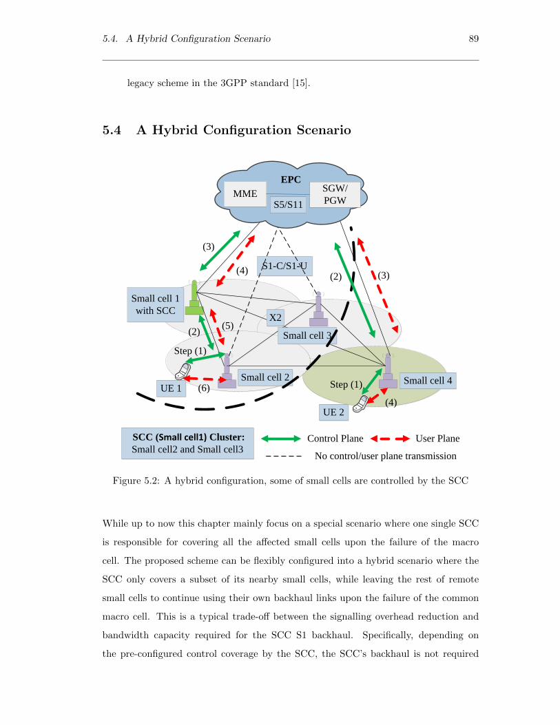
5.4. A Hybrid Configuration Scenario 89
legacy scheme in the 3GPP standard [15].
5.4 A Hybrid Configuration Scenario
S1-C/S1-U
Small cell 2 Small cell 4
X2
Small cell 3
UE 1
Small cell 1
with SCC
SCC (Small cell1) Cluster:
Small cell2 and Small cell3
UE 2
(3)
Step (1)
(2)
(2)
(4)
(5)
(3)
(4)
(6) Step (1)
Control Plane User Plane
No control/user plane transmission
EPC
MMESGW/
PGWS5/S11
Figure 5.2: A hybrid configuration, some of small cells are controlled by the SCC
While up to now this chapter mainly focus on a special scenario where one single SCC
is responsible for covering all the affected small cells upon the failure of the macro
cell. The proposed scheme can be flexibly configured into a hybrid scenario where the
SCC only covers a subset of its nearby small cells, while leaving the rest of remote
small cells to continue using their own backhaul links upon the failure of the common
macro cell. This is a typical trade-off between the signalling overhead reduction and
bandwidth capacity required for the SCC S1 backhaul. Specifically, depending on
the pre-configured control coverage by the SCC, the SCC’s backhaul is not required

90 Chapter 5. A Scalable Architecture for Handling Control Plane Failures in
Heterogeneous Networks
to match the bandwidth capacity of macro cell’s S1 interface, as those remote small
cells not covered by the SCC will use their own S1 interfaces for the user plane data
transmission upon the failure of the macro cell. For instance, in Fig. 5.2 illustrates that
some of small cells are not controlled by the SCC within a macro cell coverage. The
SCC on small cell1 takes the local control of small cell2 and small cell3 in a clustered
fashion during the macro cell fail-over period, as shown in Fig.5.2. It illustrates that
the UE1 is attached to small cell2 in the control plane and the user plane, in which case
small cell2 and small cell3 will use the split bearer for the user plane data transmission.
Furthermore, Fig.5.2 shows that only small cell4 is not controlled by the SCC within a
macro cell coverage, the UE2 is attached to small cell4 in the control plane and the user
plane, in which case small cell4 uses the secondary cell group bearer for transmission of
the user plane data. Moreover, path switch signalling messages are used to modify the
bearer for the user plane data transmission and these path switch signalling messages
are forwarded to the CN for every UE handover in the legacy scheme [15]. These path
switch signalling messages are not forwarded to the CN according to the proposed SCC
scheme, as shown in Fig. 3.2. Therefore, the UE mobility is not visible to the CN in
the proposed SCC scheme.
An example in Fig.5.3 illustrates that the designated SCC forms a group of nearby
small cells that can be arranged in hexagonal ring structure in the hybrid scenario.
The hexagonal ring structure represents the SCC’s control coverage and each hexagonal
ring composed of number of small cells. The designated SCC will be deployed in the
centre cell that is inner most ring 0 and it is surrounded by number of rings of small
cells. It can be seen from Fig. 5.3 that the small cells (small cell 2 to 19) of rings 1
and 2 are controlled by the SCC (small cell1) and small cells (small cell 20 to 37) of
ring 3 are not controlled by the SCC (small cell1). Furthermore, small cells (small cell
2 to 19) are inside the SCC control coverage will follow the proposed SCC handover
procedure, as shown in Fig. 3.2 and small cells (small cell 20 to 37) are outside of the
SCC control coverage will follow the legacy handover procedure in the 3GPP standard
[15]. Particularly, the number of rings (the number of small cells within each successive
ring increases) increase with the enlargement of the SCC control coverage size has two
simultaneous effects on handover performance. Larger control coverage size indicates

5.4. A Hybrid Configuration Scenario 91
Small cell2
(1)
Small cell1
with SCC
(0)
Small cell3
(1)
Small cell6
(1)
Small cell5
(1)
Small cell4
(1)
Small cell7
(1)
Small cell8
(2)
Small cell18
(2)
Small cell19
(2)
Small cell17
(2)
Small cell16
(2)
Small cell15
(2)Small cell14
(2)
Small cell12
(2)
Small cell13
(2)
Small cell11
(2)
Small cell10
(2)
Small cell9
(2)
Small cell20
(3)
Small cell1
(3)
Small cell22
(3)Small cell3
(3)
Small cell24
(3)
Small cell25
(3)
Small cell26
(3)Small cell27
(3)
Small cell28
(3)
Small cell29
(3)
Small cell30
(3)
Small cell31
(3)
Small cell32
(3)
Small cell33
(3)
Small cell34
(3)
Small cell35
(3)
Small cell36
(3)
Small cell37
(3)
Small cell1
with SCC
Small cells ( 2 to
19) are controlled
by the SCC
Small cells (20 to 37)
are not controlled by
the SCC
Figure 5.3: Example of hexagonal ring structure in the hybrid scenario

92 Chapter 5. A Scalable Architecture for Handling Control Plane Failures in
Heterogeneous Networks
more SCC handovers and thus less legacy handovers.
5.5 Performance Analysis
This section evaluates the performance of the proposed scheme and compares it against
the legacy scheme through the system level simulation. The network modelling frame-
work has been implemented in ns3 [81]. The network model considers that each hexag-
onal cell area is served by a small cell, and the small cells can be arranged in ring
structure, as shown in Fig.5.3. It is worth noting that, using such a ring-based topol-
ogy is effectively able to cover the consideration of different hybrid scenarios, depending
on how many rings are under the control of the SCC upon the failure of the umbrella
macro cell. For the network model, the system is configured to follow the 3GPP evolved
packet system topology and build up a network scenario which consists of one MME,
one SGW and up to 100 small cells. All the nodes are distributed within a macro cell
coverage area of 1 km2. Note that this chapter do not explicitly model the macro cell
failure in the network, but the network model assumes that the macro cell failure hap-
pened; thereafter this model evaluates the performance of the mobility management
in the network during the fail-over period only. Neighbouring small cells are intercon-
nected via physical interface. The simulation was performed at a number of average
constant velocities 2-10 km/h, and their movements were based on the ns3 inbuilt Ran-
dom Walk mobility model [85]. For instance, in the random walk model, the UEs select
a direction in which to move between 0 and 2π, a speed from a given distribution, and
then move in that direction at that speed for a given time period. The UEs were uni-
formly distributed and the user density in the given area varies from 100-300 users/km2.
The network model assumed that all UEs are always in ECM CONNECTED state, and
that all handovers were X2 based. The main simulation parameters are based on Table
3.1.
There are three performance evaluation scenarios that are identified in order to analyse
the effects of mobility management in the network:
• Cell Size Scenario: Both average user velocity and user density are constant

5.5. Performance Analysis 93
and only the cell size changes;
• User Velocity Scenario: Both cell size and average user density are constant
and only the average user velocity changes;
• User Density Scenario: Both Cell Size and average user velocity are constant
and only the average user density changes;
5.5.1 Signalling and Data Delivery Latency per UE
1.08
1.1
1.12
1.14
1.16
1.18
1.2
0
0.05
0.1
0.15
0.2
0.25
0.3
0.35
0.4
2 4 6 8 10
Rel
ativ
e dat
a del
ay
Rel
ativ
e si
gn
alli
ng
del
ay
Average User Velocity (km/h)
SCC sim-Sig,controls up to 2 rings SCC sim-Sig,controls up to 3 ringsSCC sim-Sig,controls up to 4 rings SCC sim-Sig,controls up to 5 ringsSCC sim-Data,controls up to 2 rings SCC sim-Data,controls up to 3 ringsSCC sim-Data,controls up to 4 rings SCC sim-Data,controls up to 5 rings
Signalling cost savings increases when the
number of rings and user velocity increases
Additional data cost expenditure increases when the
number of rings and user velocity increases
Figure 5.4: Effect of user velocity and ring size: Signalling and data delivery latency
per UE
This chapter first evaluates the signalling latency and the data delivery latency dur-
ing handover. The latency is calculated based on the transmission latency and the
processing latency of the messages and the calculation is based on section 3.4.1. The
transmission latency and the processing latency related parameter values are based
on Table 3.2. Fig. 5.4 illustrates the ratio of the cost of the proposed scheme to the
cost of the legacy scheme in 3GPP. It show the signalling and data delivery latency
as a function of user velocity under various ring sizes. In terms of signalling latency,
as shown in Fig. 5.4, the following observations can be made. First, more signalling
savings can be achieved when the user velocity increases. Second, the signalling latency
of the proposed scheme has less impact when the ring size increases. This is because
the UE movement within a cluster area is more likely to perform path switch operation
procedures. However the signalling latency savings come at the expense of the data

94 Chapter 5. A Scalable Architecture for Handling Control Plane Failures in
Heterogeneous Networks
delivery latency, as shown in Fig. 5.4. With the increase of user velocity, the proposed
scheme will incur more data delivery latency than the legacy scheme, because the local
X2 traffic forwarding between the designated SCC and the small cell incurs additional
latency. However, since it is the common practice that backhaul latency is higher than
the local X2 forwarding latency [14], the proposed scheme only introduces marginal
extra latency in the user plane data transmission. Specifically, the crossover point
denotes the 4 km/h would be balance point between the relative signalling delay and
the relative data delay. It can be easily discernible that 30% savings of the signalling
delay in handover and an additional 15% of the data delay are the optimal points. In
fact, this is because the UE most likely to perform path switch operations at the user
velocity of 4 km/h.
1.12
1.13
1.14
1.15
1.16
1.17
1.18
1.19
1.2
1.21
0
0.1
0.2
0.3
0.4
0.5
0.6
100 200 300 400 500
Rel
ativ
e d
ata
del
ay
Rel
ativ
e si
gn
alli
ng
del
ay
Cell size(m)
SCC sim-Sig,Avg.velocity=10
SCC sim-Data,Avg.velocity=10
Signalling cost savings
decreases when the cell
size increases
Additional data cost expenditure decreases
when the cell size increases
Figure 5.5: Effect of cell size: Signalling and data delivery latency per UE
Similar to the user velocity scenario, the signalling and data delivery latency is cal-
culated and results are shown in Fig. 5.5. It shows the signalling and data delivery
latency as a function of cell size. It is illustrated that more signalling savings can be
achieved when compared with the legacy scheme in 3GPP. Further similar to the user
velocity scenario, it can be seen from Fig. 5.5, the data delivery latency incurs addi-
tional cost due to local X2 forwarding between the SCC and small cell. However, when
the backhaul latency is higher than the local X2 traffic forwarding latency [14], which
may be a typical case in the heterogeneous network, the local X2 traffic forwarding
only introduces marginal extra latency. Therefore, the SCC scheme can be selected,

5.5. Performance Analysis 95
based on the signalling and data delivery latency requirements. Similar to the user
velocity scenario, the crossover point denotes a cell size of 200 m would be balance
point between the relative signalling delay and the relative data delay. It can be easily
discernible that 30% savings of the signalling delay in handover and an additional 16%
of the data delay are the optimal points.
5.5.2 Signalling Load at the CN
100 200 300 400 500 6000
500
1000
1500
2000
Cell Size (m)
Num
ber
of p
roce
ssed
mes
sage
s/m
in
Legacy simSCC sim
Figure 5.6: Effect of cell size: Total handover signalling load at the MME
The impact of the signalling load on the CN is evaluated in this section in terms of the
number of messages processed at the MME, as described in the handover procedure
in Fig. 3.2. Further, the signalling load calculation is based on section 3.4.2.1. The
network model considers that different cell size ranges from 100 m to 600 m are dis-
tributed under the coverage area of an MME and SGW. In this network, 300 UEs are
randomly distributed, and they randomly move within the given geographical area of
1 km2 and their average velocity is 10 km/h. Fig. 5.6 shows the number of signalling
messages processed at the MME per minute as a function of the cell size. It can be
directly inferred that the number of signalling messages processed at the MME is zero
in the proposed scheme when compared to the legacy scheme, because all small cells
are controlled and managed by the designated SCC. Moreover, the number of signalling

96 Chapter 5. A Scalable Architecture for Handling Control Plane Failures in
Heterogeneous Networks
messages generated by the legacy scheme increases when the cell size decreases, because
the path switch operation is performed for every UE handover.
2 4 6 8 10 12 140
500
1000
1500
2000
2500
3000
Average User Velocity (km/h)
Num
ber
of p
roce
ssed
mes
sage
s/m
in
Legacy simSCC sim,controls up to 2 ringsSCC sim,controls up to 3 ringsSCC sim,controls up to 4 ringsSCC sim,controls up to 5 rings
Figure 5.7: Effect of user velocity and ring size: Total handover signalling load at the
MME
In the user velocity scenario, the network model considers that 100 small cells are
distributed in the hexagonal ring structure under the coverage area of an MME and
SGW. Similar to the cell size case, 300 UEs are randomly distributed, and they move
randomly with different range of user velocities. Fig. 5.7 illustrates the number of
signalling messages processed at the MME per minute as a function of the average
user velocity under various ring sizes. The signalling load generated by the legacy
scheme increases when the user velocity increases, because the UE performs path switch
operation for every handover in the legacy scheme as compared with the proposed
scheme. As stated earlier, the path switch signalling messages are not forwarded to the
CN by the SCC when a UE moves from one small cell to another small cell within a
SCC cluster. As can be seen in Fig. 5.7, the growth of the number of rings (number of
small cells) enlarges the SCC control coverage size. Larger cluster size indicates higher
handover cost, but this condition also means more intra SCC handovers in the SCC
cluster and thus less legacy handovers.

5.5. Performance Analysis 97
Therefore it can be easily inferred that more signalling savings can be achieved when the
number of rings covered by the designated SCC increases. Specifically, the signalling
load becomes zero in the proposed scheme when all the small cells (up to ring size=5)
are controlled and managed by the designated SCC.
100 150 200 250 3000
500
1000
1500
2000
Average User Density (users/km2)
Num
ber
of p
roce
ssed
mes
sage
s/m
in
Legacy simSCC sim,controls up to 2 ringsSCC sim,controls up to 3 ringsSCC sim,controls up to 4 ringsSCC sim,controls up to 5 rings
Figure 5.8: Effect of user density and ring size: Total handover signalling load at the
MME
In the user density scenario, the network model considers that 100 small cells are
distributed in the hexagonal ring structure and all UEs randomly move with average
velocity of 10 km/h. Fig. 5.8 shows the number of signalling messages processed at
the MME per minute as a function of the average user density under various ring
sizes. Similar to the user velocity case, more signalling load savings can be achieved
in the proposed scheme when the user density increases and the number of rings are
controlled by the designated SCC increases. It is clearly shown that the proposed
scheme can significantly reduce the signalling load on the CN in all three scenarios.
Therefore, the proposed scheme is able to bring signalling benefits for heterogeneous
network and it can be selected based on the cell size, user velocity, user density and
ring size requirements.

98 Chapter 5. A Scalable Architecture for Handling Control Plane Failures in
Heterogeneous Networks
5.6 Summary
The separation between the control plane and the user plane is a key property of
the newly proposed heterogeneous networks that will be widely deployed in 5G. In
contrast to the failure of a small cell in the user plane which can be directly handled by
the associated macro cell, the solution to handling a macro cell failure in the control
plane is less investigated, in particular with regard to the signalling scalability issues
of having all the affected small cells directly communicate with the CN. This chapter
applies the proposed SCC scheme in Chapter 3, which takes the control of small cells
in a clustered fashion upon the failure of the umbrella macro cell in the heterogeneous
network environment. In this way, frequent handover signalling can be in the same
way as in heterogeneous network upon the failure of the macro cell that involved in the
control plane. As such, recreation of the secondary cell group bearer will be avoided on
the CN for every UE handover as compared with the legacy scheme in 3GPP. Without
the loss of generality, the proposed scheme can be flexibly configured into a ring-based
hybrid scenario where nearby small cells can be directly controlled by the SCC itself,
while remote small cells can remain independent with their own backhaul links to the
CN for signalling and data transmission. Moreover, the simulation results show that the
processing load (in terms of number of signalling messages processed) can be reduced
significantly at the CN, whereas the local X2 traffic forwarding only introduces marginal
extra load, which is relatively moderate. Specifically, the proposed SCC scheme reduces
the signalling gain up to 100% on the CN in all three scenarios.
Therefore, based on the cell size, latency requirements and mobility pattern, an appro-
priate ring size and the proposed SCC can be selected. As a final remark, the proposed
scheme to be applied is not visible to the CN or UEs, and an incremental upgrade is
necessary only at the RAN side.

Chapter 6
Conclusions and Future Work
6.1 Conclusions
The work described in this thesis has been concerned with the signalling architecture,
especially in a large-scale small cell network. Particularly, three main research con-
tributions that have been proposed relating to signalling architecture in a large-scale
environment: Firstly, a new signalling architecture is proposed for dense small cell net-
works in order to reduce the frequent handovers to the CN. Based on the proposed
signalling architecture, the clustering optimization algorithm is proposed in order to
select the optimal SCC in a highly user density environment and finally, the proposed
SCC scheme is applied in heterogeneous network in order to enable small cells to work
autonomously upon the failure of the corresponding macro cell. These may be sum-
marised as:
• In order to achieve effective signalling reduction on the CN, a new RAN signalling
architecture with clustered small cells is introduced that supports by an entity
called SCC. This SCC is introduced to the existing base station on the RAN
side. It controls and manages a cluster of small cells and maintains associated
forwarding information for UEs within a localized mobility management domain.
In order to achieve such a feature, the proposed signalling architecture also intro-
duced the corresponding local signalling mechanism for the X2-based handover
procedure. The simulation results show that the proposed signalling architecture
99

100 Chapter 6. Conclusions and Future Work
is able to achieve the signalling reduction gain by up to 58.1% on the CN with
various cell sizes when compared to the legacy scheme in 3GPP. Moreover, it
reduces the signalling gain by up to 41.8% on the CN with various user velocities
when compared to the legacy scheme in 3GPP. In fact, the proposed signalling
architecture saves more signalling load and signalling latency when compared
against the anchor scheme in [4].
• Further research has been carried out for selecting the optimal SCC in dense
small cell networks. Thus, this research proposed the clustering optimization
algorithm. From a scalability perspective, this algorithm is designed to select
multiple optimal SCCs due to the growth in number of small cells in a large-
scale environment. Specifically, this algorithm is designed to form the traffic-load
balanced clusters in a highly user density environment. The simulation results
show that more signalling load and signalling cost savings can be achieved in the
proposed algorithm when compared against the legacy scheme in 3GPP and the
anchor scheme in [4]. Particularly, the proposed algorithm reduces the signalling
gain by up to 85.48% on the CN with various number of cells and it reduces the
signalling gain by up to 82.9% on the CN with the number of SCCs is three in
both the user velocity and user density scenarios.
• Finally, research has been carried out for tackling the control plane failures of
small cells in heterogeneous network when the macro cell is failed. As such net-
work, this research applies the proposed SCC scheme, which takes the control
of affected small cells in a clustered fashion and it avoids the unnecessary han-
dover signalling load to the CN incurred by UEs frequent mobility. Further, this
research also proposed a hybrid configuration scenario in heterogeneous network
during the macro cell fail-over period. This hybrid scenario forms a cluster of
nearby small cells, while leaving the rest of small cells directly connected to the
CN. The simulation results show that significant signalling load and signalling
cost can be saved in the proposed scheme when compared against the legacy
scheme in 3GPP. Particularly, the proposed SCC scheme reduces the signalling
gain by up to 100% on the CN in all three scenarios.

6.2. Future Works 101
The comparison between the cluster based approach and hybrid based approach in
small cell networks is shown in table 6.1.
Table 6.1: Comparison between the cluster based approach and hybrid based approach
in small cell networks
Parameters Cluster Based Approach Hybrid Based Approach
How clusters are formed Clustering optimization tech-
nique
Ring based technique
Time complexity O(Mnt) M=Number of clus-
ters n= No of cells t= No of
iterations
O(Rnt) M=Number of rings
n= No of cells t= No of itera-
tions
Deployment scenarios Sparse populated areas Dense populated areas
Intra SCC scheme support Yes Yes
Inter SCC scheme support Yes No
Scalability Yes Yes
Handover signalling delay Average Low
Centralized architecture support Yes Yes
6.2 Future Works
There are still a few open problems for future research. These problems suggest a
variety of directions in which the present work that can be extended as follows:
• Since the proposed signalling architecture must be able to provide the optimal
operating points based on the given scenarios in dense mobile networks. Further,
this research work can be extended to support and locate other optimal operating
points based on the system requirements.
• Paging is one of the important challenges in small cell networks. As stated earlier
in Chapter 2, paging broadcast generates a high volume of signalling load that

102 Chapter 6. Conclusions and Future Work
may lead to small cells overload. This signalling load can be reduced by applying
the proposed SCC scheme. The proposed SCC scheme can be extended further
to support the idle mode UEs and it allows paging initiated only to the group of
small cells within a TA since the SCC is directly connected to the MME.
• The TAU is an another important challenge in small cell networks as discussed
earlier in Chapter 2. The poor configuration of TA causes a large number of
TAU signalling messages on the CN. These signalling messages can be reduced
by applying the proposed SCC scheme. Similar to the paging case, the SCC
scheme can be extended further to support the idle mode UEs. Particularly, the
proposed SCC scheme is able to detect the UE movement between the TA areas
and then the TA list can be optimized further. Moreover, this TAU reduction
can extend the UE’s battery lifetime.
• This research is not limited to the mobility management only; the proposed SCC
scheme can be extended to support other research areas such as coverage and
interference management as discussed in Chapter 2. Specifically, these areas can
be improved by using self-optimization network (SON) approach. This approach
can easily fit into the proposed SCC scheme since the SCC is directly connected
to all small cells within its cluster. Further, this approach can extend to support
mobility load balancing use case as well.

Bibliography
[1] K. Kweon, J. Park, J. Lee, S. Baek, and A. Yegin, “Energy efficient ip reachability
for push service in natted lte systems,” in Communications (ICC), 2014 IEEE
International Conference on, June 2014, pp. 2526–2531.
[2] S. Liu, J. Wu, C. H. Koh, and V. Lau, “A 25 gb/s(/km2) urban wireless network
beyond imt-advanced,” Communications Magazine, IEEE, vol. 49, no. 2, pp. 122–
129, February 2011.
[3] 3GPP TR 36.839 v11.1.0, “Mobility enhancements in heterogeneous networks,”
Dec 2012.
[4] R. Balakrishnan and I. Akyildiz, “Local anchor schemes for seamless and low-cost
handover in coordinated small cells,” Mobile Computing, IEEE Transactions on,
vol. PP, no. 99, pp. 1–1, 2015.
[5] 3GPP TR 36.814, Version 9.0.0, “Evolved universal terrestrial radio access (e-
utra); further advancements for e-utra physical layer aspects,” Mar 2010.
[6] 3GPP TR 36.932 V12.1.0, “Scenarios and requirements for small cell enhance-
ments for EUTRA and EUTRAN,” Oct. 2014.
[7] J. Robson, “Small cell backhaul requirements,” Next Generation Mobile Networks,
White Paper, June 2012.
[8] C. broadband networks, “Small cell deployment strategies and best practice back-
haul,” White Paper, August 2012.
103
104 Bibliography
[9] “Ofcom unveils plans for 4G auction of the airwaves,” Ofcom, Tech. Rep., July
2012.
[10] Small Cell Forum Document 156.05.01, “Deployment issues for rural and remote
small cells,” February 2015.
[11] Small Cell Forum Version 2.02, “Business drivers for connecting the unconnected
via small cells,” Feb 2015.
[12] Small Cell Forum Document 153.05.01, “Rural and remote small cell network ar-
chitectures,” March 2015.
[13] J. Ferragut and J. Mangues-Bafalluy, “A self-organized tracking area list mecha-
nism for large-scale networks of femtocells,” in Communications (ICC), 2012 IEEE
International Conference on, June 2012, pp. 5129–5134.
[14] T. Guo, A. ul Quddus, N. Wang, and R. Tafazolli, “Local Mobility Management
for Networked Femtocells Based on X2 Traffic Forwarding,” Vehicular Technology,
IEEE Transactions on, vol. 62, no. 1, pp. 326–340, Jan 2013.
[15] 3GPP TS 36.300 V13.1.0, “Evolved Universal Terrestrial Radio Access (E-UTRA)
and Evolved Universal Terrestrial Radio Access Network (E-UTRAN); Overall
description,” Sep. 2015.
[16] V. Chandrasekhar and J. Andrews, “Uplink capacity and interference avoidance
for two-tier femtocell networks,” Wireless Communications, IEEE Transactions
on, vol. 8, no. 7, pp. 3498–3509, July 2009.
[17] L. Ho and H. Claussen, “Effects of user-deployed, co-channel femtocells on the call
drop probability in a residential scenario,” in Personal, Indoor and Mobile Radio
Communications, 2007. PIMRC 2007. IEEE 18th International Symposium on,
Sept 2007, pp. 1–5.
[18] H. Song, X. Fang, and L. Yan, “Handover scheme for 5g c/u plane split heteroge-
neous network in high-speed railway,” Vehicular Technology, IEEE Transactions
on, vol. 63, no. 9, pp. 4633–4646, Nov 2014.

Bibliography 105
[19] C. Coletti, L. Hu, N. Huan, I. Kovacs, B. Vejlgaard, R. Irmer, and N. Scully, “Het-
erogeneous deployment to meet traffic demand in a realistic lte urban scenario,”
in Vehicular Technology Conference (VTC Fall), 2012 IEEE, Sept 2012, pp. 1–5.
[20] J. Andrews, H. Claussen, M. Dohler, S. Rangan, and M. Reed, “Femtocells: Past,
present, and future,” Selected Areas in Communications, IEEE Journal on, vol. 30,
no. 3, pp. 497–508, April 2012.
[21] G. T. RP-040461, “Proposed study item on evolved utra and utran,” December
2004.
[22] “Requirements for evolved utra (e-utra) and evolved utran (e-utran),” 3GPP TS
25.913, Version 9.0.0, Feb 2010.
[23] H. Ekstrom, A. Furuskar, J. Karlsson, M. Meyer, S. Parkvall, J. Torsner, and
M. Wahlqvist, “Technical solutions for the 3g long-term evolution,” Communica-
tions Magazine, IEEE, vol. 44, no. 3, pp. 38–45, 2006.
[24] Wikipedia, “Home enodeb,” March 2014. [Online]. Available: https://en.
wikipedia.org/wiki/Home eNode B
[25] 3GPP TS 36.420 V12.1.0, “X2 general aspects and principles,” Feb 2015.
[26] “S1 general aspects and principles,” 3GPP TS 36.410, Version 12.1.0, February
2015.
[27] 3GPP TS 36.413 V12.6.0, “S1 application protocol (s1ap),” Jul 2015.
[28] 3GPP TS 29.274, Version 13.3.0, “Evolved general packet radio service (gprs) tun-
nelling protocol for control plane (gtpv2-c),” Sep 2015.
[29] 3GPP TS 23.402, Version 13.4.0, “Architecture enhancements for non-3gpp ac-
cesses,” Dec 2015.
[30] 3GPP TS 29.061, Version 13.2.0, “Interworking between the public land mobile
network (plmn) supporting packet based services and packet data networks (pdn),”
Dec 2015.

106 Bibliography
[31] 3GPP TS 36.304, Version 12.6.0, “Evolved universal terrestrial radio access (e-
utra); user equipment (ue) procedures in idle mode,” Nov 2015.
[32] X. Cao and L. Liu, “Research of the rrc layer idle state in td-lte,” in Educational
and Information Technology (ICEIT), 2010 International Conference on, vol. 3,
Sept 2010, pp. V3–349–V3–352.
[33] C. Qian, W. Zhang, and W. Zhou, “Performance evaluation of reference signal
received power strength based idle users’ cell selection in 3gpp lte,” in Vehicular
Technology Conference (VTC Spring), 2013 IEEE 77th, June 2013, pp. 1–5.
[34] J. Wang, J. Liu, D. Wang, J. Pang, and G. Shen, “Optimized fairness cell selection
for 3gpp lte-a macro-pico hetnets,” in Vehicular Technology Conference (VTC
Fall), 2011 IEEE, Sept 2011, pp. 1–5.
[35] M. Simsek, H. Wu, B. Zhao, T. Akbudak, and A. Czylwik, “Performance of dif-
ferent cell selection modes in 3gpp-lte macro-/femtocell scenarios,” in Wireless
Advanced (WiAd), 2011, June 2011, pp. 126–131.
[36] T. Qu, D. Xiao, D. Yang, W. Jin, and Y. He, “Cell selection analysis in outdoor het-
erogeneous networks,” in Advanced Computer Theory and Engineering (ICACTE),
2010 3rd International Conference on, vol. 5, Aug 2010, pp. V5–554–V5–557.
[37] 3GPP TS 23.002, Version 13.4.0, “Network architecture,” Dec 2015.
[38] 3GPP TS 23.401 V13.4.0, “General Packet Radio Service (GPRS) enhancements
for Evolved Universal Terrestrial Radio Access Network (E-UTRAN) access,” Sep.
2015.
[39] T. Deng, X. Wang, P. Fan, and K. Li, “Modeling and performance analysis of
tracking area list-based location management scheme in lte networks,” Vehicular
Technology, IEEE Transactions on, vol. PP, no. 99, pp. 1–1, 2015.
[40] S. Razavi and D. Yuan, “Reducing signaling overhead by overlapping tracking
area list in lte,” in Wireless and Mobile Networking Conference (WMNC), 2014
7th IFIP, May 2014, pp. 1–7.

Bibliography 107
[41] Y. Bejerano, A. Smith, J. Naor, and N. Immorlica, “Efficient location area planning
for personal communication systems,” Networking, IEEE/ACM Transactions on,
vol. 14, no. 2, pp. 438–450, April 2006.
[42] E. Cayirci and I. Akyildiz, “Optimal location area design to minimize registration
signaling traffic in wireless systems,” Mobile Computing, IEEE Transactions on,
vol. 2, no. 1, pp. 76–85, Jan 2003.
[43] I. Demirkol, C. Ersoy, M. Caglayan, and H. Delic, “Location area planning and
cell-to-switch assignment in cellular networks,” Wireless Communications, IEEE
Transactions on, vol. 3, no. 3, pp. 880–890, May 2004.
[44] Y. W. Chung, “Adaptive design of tracking area list in lte,” in Wireless and Optical
Communications Networks (WOCN), 2011 Eighth International Conference on,
May 2011, pp. 1–5.
[45] S. Razavi, D. Yuan, F. Gunnarsson, and J. Moe, “Exploiting Tracking Area List
for Improving Signaling Overhead in LTE,” in Vehicular Technology Conference
(VTC 2010-Spring), 2010 IEEE 71st, May 2010, pp. 1–5.
[46] H. Safa and N. Ahmad, “Tabu search based approach to solve the tas reconfigu-
ration problem in lte networks,” in Advanced Information Networking and Appli-
cations (AINA), 2015 IEEE 29th International Conference on, March 2015, pp.
593–599.
[47] 3GPP TS 24.301, Version 13.4.0, “Non-access-stratum (nas) protocol for evolved
packet system (eps),” Dec 2015.
[48] S. Razavi, D. Yuan, F. Gunnarsson, and J. Moe, “Dynamic Tracking Area List
configuration and performance evaluation in LTE,” in GLOBECOM Workshops
(GC Wkshps), 2010 IEEE, Dec 2010, pp. 49–53.
[49] R.-H. Liou, Y.-B. Lin, and S.-C. Tsai, “An investigation on lte mobility manage-
ment,” Mobile Computing, IEEE Transactions on, vol. 12, no. 1, pp. 166–176,
2013.

108 Bibliography
[50] A. Chekkouri, A. Ezzouhairi, and S. Pierre, “X2 based local mobility management
for networked femtocells,” in Wireless and Mobile Computing, Networking and
Communications (WiMob), 2013 IEEE 9th International Conference on, Oct 2013,
pp. 622–629.
[51] A. Rath and S. Panwar, “Fast handover in cellular networks with femtocells,” in
Communications (ICC), 2012 IEEE International Conference on, June 2012, pp.
2752–2757.
[52] F. Zdarsky, A. Maeder, S. Al-Sabea, and S. Schmid, “Localization of data and
control plane traffic in enterprise femtocell networks,” in Vehicular Technology
Conference (VTC Spring), 2011 IEEE 73rd, May 2011, pp. 1–5.
[53] L. Wang, Y. Zhang, and Z. Wei, “Mobility management schemes at radio network
layer for lte femtocells,” in Vehicular Technology Conference, 2009. VTC Spring
2009. IEEE 69th, April 2009, pp. 1–5.
[54] “Study on small cell enhancements for eutra and eutran higher layer aspects,”
3GPP TS 36.842, Version 0.2.0, may 2013.
[55] X. Ge, H. Cheng, M. Guizani, and T. Han, “5g wireless backhaul networks: chal-
lenges and research advances,” Network, IEEE, vol. 28, no. 6, pp. 6–11, Nov 2014.
[56] J. Hoydis, M. Kobayashi, and M. Debbah, “Green small-cell networks,” Vehicular
Technology Magazine, IEEE, vol. 6, no. 1, pp. 37–43, March 2011.
[57] V. Capdevielle, A. Feki, and E. Sorsy, “Joint interference management and han-
dover optimization in lte small cells network,” in Communications (ICC), 2012
IEEE International Conference on, 2012, pp. 6769–6773.
[58] T. Yamamoto and S. Konishi, “Impact of small cell deployments on mobility per-
formance in lte-advanced systems,” in Personal, Indoor and Mobile Radio Com-
munications (PIMRC Workshops), 2013 IEEE 24th International Symposium on,
Sept 2013, pp. 189–193.
[59] S. Barbera, P. Michaelsen, M. Saily, and K. Pedersen, “Mobility performance of

Bibliography 109
lte co-channel deployment of macro and pico cells,” in Wireless Communications
and Networking Conference (WCNC), 2012 IEEE, April 2012, pp. 2863–2868.
[60] P. Munoz, R. Barco, and I. de la Bandera, “On the potential of handover pa-
rameter optimization for self-organizing networks,” Vehicular Technology, IEEE
Transactions on, vol. 62, no. 5, pp. 1895–1905, Jun 2013.
[61] S. Jha, K. Sivanesan, R. Vannithamby, and A. Koc, “Dual connectivity in lte
small cell networks,” in Globecom Workshops (GC Wkshps), 2014, Dec 2014, pp.
1205–1210.
[62] B. Bangerter, S. Talwar, R. Arefi, and K. Stewart, “Networks and devices for the
5G era,” Communications Magazine, IEEE, vol. 52, no. 2, pp. 90–96, February
2014.
[63] 3GPP TR 23.857 V11.0.0, “Study of Evolved Packet Core (EPC) nodes restora-
tion,” Dec. 2012.
[64] T. Taleb and K. Samdanis, “Ensuring service resilience in the eps: Mme failure
restoration case,” in Global Telecommunications Conference (GLOBECOM 2011),
2011 IEEE, 2011, pp. 1–5.
[65] P.-C. Lu, K.-J. Tsao, C.-R. Huang, and T.-C. Hou, “A suburban femtocell model
for evaluating signal quality improvement in wimax networks with femtocell base
stations,” in Wireless Communications and Networking Conference (WCNC),
2010 IEEE, April 2010, pp. 1–6.
[66] H. Claussen, L. Ho, and L. Samuel, “Self-optimization of coverage for femtocell de-
ployments,” in Wireless Telecommunications Symposium, 2008. WTS 2008, April
2008, pp. 278–285.
[67] H. Claussen and F. Pivit, “Femtocell coverage optimization using switched multi-
element antennas,” in Communications, 2009. ICC ’09. IEEE International Con-
ference on, June 2009, pp. 1–6.
[68] H. Liang, Z. Yiqing, W. Yuanyuan, H. Xue, S. Jinglin, and C. Xunxun, “Advanced

110 Bibliography
coverage optimization techniques for small cell clusters,” Communications, China,
vol. 12, no. 8, pp. 111–122, August 2015.
[69] L. Huang, Y. Zhou, X. Han, Y. Wang, M. Qian, and J. Shi, “Distributed cov-
erage optimization for small cell clusters using game theory,” in Wireless Com-
munications and Networking Conference (WCNC), 2013 IEEE, April 2013, pp.
2289–2293.
[70] D. Xenakis, N. Passas, L. Merakos, and C. Verikoukis, “Energy-efficient and
interference-aware handover decision for the lte-advanced femtocell network,” in
Communications (ICC), 2013 IEEE International Conference on, 2013, pp. 2464–
2468.
[71] A. Feki, V. Capdevielle, L. Roullet, and A. Sanchez, “Handover aware interference
management in lte small cells networks,” in Modeling Optimization in Mobile, Ad
Hoc Wireless Networks (WiOpt), 2013 11th International Symposium on, 2013,
pp. 49–53.
[72] Y.-P. Zhang, S. Feng, P. Zhang, L. Xia, Y. chun Wu, and X. Ren, “Inter-cell
interference management in lte-a small-cell networks,” in Vehicular Technology
Conference (VTC Spring), 2013 IEEE 77th, June 2013, pp. 1–6.
[73] Y.-P. Zhang, S. Feng, and P. Zhang, “Adaptive cell association and interference
management in lte-a small-cell networks,” in Vehicular Technology Conference
(VTC Fall), 2013 IEEE 78th, Sept 2013, pp. 1–6.
[74] A. Zakrzewska, D. Lopez-Perez, S. Kucera, and H. Claussen, “Dual connectivity
in lte hetnets with split control- and user-plane,” in Globecom Workshops (GC
Wkshps), 2013 IEEE, Dec 2013, pp. 391–396.
[75] A. Mukherjee, “Macro-small cell grouping in dual connectivity lte-b networks with
non-ideal backhaul,” in Communications (ICC), 2014 IEEE International Confer-
ence on, June 2014, pp. 2520–2525.
[76] H. Ishii, Y. Kishiyama, and H. Takahashi, “A novel architecture for lte-b :c-

Bibliography 111
plane/u-plane split and phantom cell concept,” in Globecom Workshops (GC Wk-
shps), 2012 IEEE, 2012, pp. 624–630.
[77] K. Pedersen, P. Michaelsen, C. Rosa, and S. Barbera, “Mobility enhancements for
lte-advanced multilayer networks with inter-site carrier aggregation,” Communi-
cations Magazine, IEEE, vol. 51, no. 5, pp. 64–71, May 2013.
[78] J. Zhang, C. Sun, Y. Yi, and H. Zhuang, “A hybrid framework for capacity and
coverage optimization in self-organizing lte networks,” in Personal Indoor and Mo-
bile Radio Communications (PIMRC), 2013 IEEE 24th International Symposium
on, 2013, pp. 2919–2923.
[79] Y. Li and I.-R. Chen, “Design and performance analysis of mobility management
schemes based on pointer forwarding for wireless mesh networks,” Mobile Com-
puting, IEEE Transactions on, vol. 10, no. 3, pp. 349–361, March 2011.
[80] R. Langar, N. Bouabdallah, and R. Boutaba, “A comprehensive analysis of mobil-
ity management in mpls-based wireless access networks,” Networking, IEEE/ACM
Transactions on, vol. 16, no. 4, pp. 918–931, Aug 2008.
[81] The ns-3 network simulator. [Online]. Available: http://www.nsnam.org/
[82] R. Rohankar, R. Bhatia, V. Shrivastava, and D. Sharma, “Performance analysis
of various routing protocols (proactive and reactive) for random mobility models
of adhoc networks,” in Recent Advances in Information Technology (RAIT), 2012
1st International Conference on, March 2012, pp. 331–335.
[83] M. Singh, S.-G. Lee, D. Singh, and H. J. Lee, “Impact and performance of mobil-
ity models in wireless ad-hoc networks,” in Computer Sciences and Convergence
Information Technology, 2009. ICCIT ’09. Fourth International Conference on,
Nov 2009, pp. 139–143.
[84] L. Madany, M. Madkour, and A. Al-Talhi, “Characteristics of mobility models for
mobile ad hoc networks,” in Signal and Image Processing Applications (ICSIPA),
2009 IEEE International Conference on, Nov 2009, pp. 554–558.

112 Bibliography
[85] K.-H. Chiang and N. Shenoy, “A 2-d random-walk mobility model for location-
management studies in wireless networks,” Vehicular Technology, IEEE Transac-
tions on, vol. 53, no. 2, pp. 413–424, March 2004.
[86] 3GPP TR 25.912 V12.0.0, “Feasibility study for evolved Universal Terrestrial Ra-
dio Access (UTRA) and Universal Terrestrial Radio Access Network (UTRAN),”
Oct. 2014.
[87] A. Keranen and J. Ott, “Increasing reality for DTN protocol simulations,” Net-
working Laboratory, Helsinki University of Technology, TR, 2007.
[88] 3GPP TS 23.007 V13.2.0, “Restoration procedures,” Sep. 2015.


![1 Wireless Resources Virtualization for Cloud Radio Access ... · Access Network (C-RAN) as a new platform for future mobile network infrastructure [4]. In C-RAN, the baseband processing](https://static.fdocuments.in/doc/165x107/605ea79ddb649a73e938db7d/1-wireless-resources-virtualization-for-cloud-radio-access-access-network-c-ran.jpg)