Radio Access Network Architecture and Protocols · • Aggregate Maximum Bit Rate (AMBR) per group...
36
© 3GPP 2011 3GPP Workshop, Bangalore, 30 May 2011 1 Radio Access Network Architecture and Protocols Benoist Sébire Nokia Siemens Networks 3GPP TSG-RAN WG2
Transcript of Radio Access Network Architecture and Protocols · • Aggregate Maximum Bit Rate (AMBR) per group...

THE Mobile Broadband Standard
© 3GPP 2011 3GPP Workshop, Bangalore, 30 May 2011 1
Radio Access Network Architecture and Protocols
Benoist Sébire
Nokia Siemens Networks
3GPP TSG-RAN WG2

THE Mobile Broadband Standard
© 3GPP 2011 3GPP Workshop, Bangalore, 30 May 2011
Contents
E-UTRAN Overview• Architecture, Functions
Protocol Architecture• User Plane, Control Plane
Some Highlights• QoS, Reliability, Mobility, Latency
Rel-10• Overview, Carrier Aggregation, Minimisation of Drive Tests
2

THE Mobile Broadband Standard
© 3GPP 2011 3GPP Workshop, Bangalore, 30 May 2011
E-UTRAN Architecture and Functions
3

THE Mobile Broadband Standard
© 3GPP 2011 3GPP Workshop, Bangalore, 30 May 2011
E-UTRAN Architecture
E-UTRAN consists of eNBs• flat architecture (no RNC or BSC as in UTRAN and
GERAN) for reduced latency and delays
eNBs are interconnected with each other by means of the X2 interface• can be a logical connection via CN elements
eNBs are also connected to the Evolved Packet Core (EPC)• eNBs are connected to the Mobility Management
Entity (MME) via the S1-MME interface
• eNBs are connected to the to the Serving Gateway (S-GW) by means of the S1-U interface
4
eNB
MME / S-GW MME / S-GW
eNB
eNB
S1
S1
S1
S1
X2
X2
X2
E-UTRAN
THE Mobile Broadband Standard
© 3GPP 2011 3GPP Workshop, Bangalore, 30 May 2011
E-UTRAN Functions
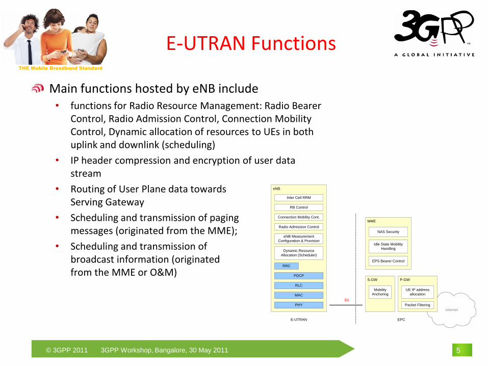
Main functions hosted by eNB include• functions for Radio Resource Management: Radio Bearer
Control, Radio Admission Control, Connection Mobility Control, Dynamic allocation of resources to UEs in both uplink and downlink (scheduling)
• IP header compression and encryption of user data stream
• Routing of User Plane data towards Serving Gateway
• Scheduling and transmission of pagingmessages (originated from the MME);
• Scheduling and transmission of broadcast information (originated from the MME or O&M)
5
internet
eNB
RB Control
Connection Mobility Cont.
eNB Measurement
Configuration & Provision
Dynamic Resource
Allocation (Scheduler)
PDCP
PHY
MME
S-GW
S1
MAC
Inter Cell RRM
Radio Admission Control
RLC
E-UTRAN EPC
RRC
Mobility
Anchoring
EPS Bearer Control
Idle State Mobility
Handling
NAS Security
P-GW
UE IP address
allocation
Packet Filtering
THE Mobile Broadband Standard
© 3GPP 2011 3GPP Workshop, Bangalore, 30 May 2011
Protocol Architecture
6
THE Mobile Broadband Standard
© 3GPP 2011 3GPP Workshop, Bangalore, 30 May 2011
User Plane
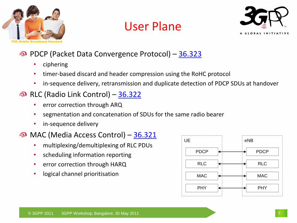
PDCP (Packet Data Convergence Protocol) – 36.323• ciphering
• timer-based discard and header compression using the RoHC protocol
• in-sequence delivery, retransmission and duplicate detection of PDCP SDUs at handover
RLC (Radio Link Control) – 36.322• error correction through ARQ
• segmentation and concatenation of SDUs for the same radio bearer
• in-sequence delivery
MAC (Media Access Control) – 36.321• multiplexing/demultiplexing of RLC PDUs
• scheduling information reporting
• error correction through HARQ
• logical channel prioritisation
7
eNB
PHY
UE
PHY
MAC
RLC
MAC
PDCPPDCP
RLC

THE Mobile Broadband Standard
© 3GPP 2011 3GPP Workshop, Bangalore, 30 May 2011
User Plane
8
Multiplexing
...
HARQ
Scheduling / Priority Handling
Transport Channels
MAC
RLC
PDCP
Segm.
ARQ etc
Segm.
ARQ etc
Logical Channels
ROHC ROHC
Radio Bearers
Security Security
UL-SCH

THE Mobile Broadband Standard
© 3GPP 2011 3GPP Workshop, Bangalore, 30 May 2011
User Plane
9
PDCP SDU
IP PayloadHeader
H
IP PDU#1Radio Bearer 1
MAC SDU
CRCTransport Block
H
H H
RLC SDU
H
RLC PDU RLC PDU
Multiplexing
MAC SDU
PD
CP
RLC
MA
CP
HY
SN PDCP SDU
IP PayloadHeader
H
IP PDU#2Radio Bearer 1
RLC SDU
SN
RLC SDU
PDCP SDU
IP PayloadHeader
H
IP PDU#2Radio Bearer 2
SN

THE Mobile Broadband Standard
© 3GPP 2011 3GPP Workshop, Bangalore, 30 May 2011
Control Plane
RRC (Radio Resource Control) – 36.331• Broadcast of system information, paging, RRC connection management, RB control,
mobility functions, UE measurement reporting and control
PDCP (Packet Data Convergence Protocol) – 36.323• Ciphering and integrity protection
RLC (Radio Link Control) – 36.322• Error Correction through ARQ, (re)-Segmentation according to the size of the TB,
concatenation of SDUs for the same radio bearer, in-sequence delivery
MAC (Media Access Control) – 36.321• Multiplexing/demultiplexing of RLC PDUs,
error correction through HARQ, Logical Channel Prioritisation
10
eNB
PHY
UE
PHY
MAC
RLC
MAC
MME
RLC
NAS NAS
RRC RRC
PDCP PDCP

THE Mobile Broadband Standard
© 3GPP 2011 3GPP Workshop, Bangalore, 30 May 2011
Control Plane
Only two RRC states• idle and connected
Idle mode• UE known in EPC, has an IP address and its location known on Tracking Area level
• UE-based cell-selection and tracking area update to EPC
• MME initiates paging in the whole tracking areas indicated by the UE
Connected mode• UE known in E-UTRAN and its location known on Cell level
• Mobility is UE-assisted, network-controlled
• Discontinuous Data Reception (DRX) supported for power saving
11

THE Mobile Broadband Standard
© 3GPP 2011 3GPP Workshop, Bangalore, 30 May 2011
E-UTRAN Highlights
QoS
Reliability
Mobility
Latency
12

THE Mobile Broadband Standard
© 3GPP 2011 3GPP Workshop, Bangalore, 30 May 2011
QoS
E-UTRAN is responsible for Radio Bearer management and therefore ensuring QoS over the radio• one-to-one mapping between EPS bearer, E-RAB and Radio Bearer
13
P-GWS-GW Peer
Entity
UE eNB
EPS Bearer
Radio Bearer S1 Bearer
End-to-end Service
External Bearer
Radio S5/S8
Internet
S1
E-UTRAN EPC
Gi
E-RAB S5/S8 Bearer

THE Mobile Broadband Standard
© 3GPP 2011 3GPP Workshop, Bangalore, 30 May 2011
QoS
RB establishment based on QoS parameters from MME• QoS Class Identifier (QCI) per bearer : scalar value which identifies a particular
service in terms of resource type, priority, packet delay budget and packet error rate [23.203]
• Guaranteed Bit Rate (GBR) and Maximum Bit Rate (MBR) per bearer• Aggregate Maximum Bit Rate (AMBR) per group of bearers
RB Scheduling based on QoS parameters from MME and scheduling information from UE• Channel Quality Indication• Buffer Status Report• Power Headroom Report
Scheduling for downlink is eNB implementation specificScheduling for uplink is only partially specified• Logical channel prioritization and avoid starvation [36.321]
14

THE Mobile Broadband Standard
© 3GPP 2011 3GPP Workshop, Bangalore, 30 May 2011
Reliability
L1 applies 24 bit CRC protection to transport blocks (MAC PDUs)• erroneous transport blocks are discarded on L1
Hybrid ARQ (HARQ) protocol in MAC + ARQ protocol in RLC• high reliability and radio efficiency
• HARQ feedback sent on L1/L2 control channel• Single, un-coded bit (low overhead)• Sent for each scheduled subframe (fast)• Retransmissions are soft-combined with previous attempt (efficient)
• ARQ status report sent as MAC data• RLC Status is sent on demand (poll, timer, gap detection)• protected by CRC and HARQ retransmissions
Both HARQ and ARQ protocols operate between the eNB and UE• fast handling of residual HARQ errors
Ensures low latency and high reliability
15
THE Mobile Broadband Standard
© 3GPP 2011 3GPP Workshop, Bangalore, 30 May 2011
Mobility
Handover Principles• Lossless: packets are forwarded from the source to the target
• Network-controlled : target cell is selected by the network, not by the UE and Handover control in E-UTRAN (not in packet core)
• UE-assisted : measurements are made and reported by the UE to the network
• Late path switch: only once the handover is successful, the packet core is involved
16
THE Mobile Broadband Standard
© 3GPP 2011 3GPP Workshop, Bangalore, 30 May 2011
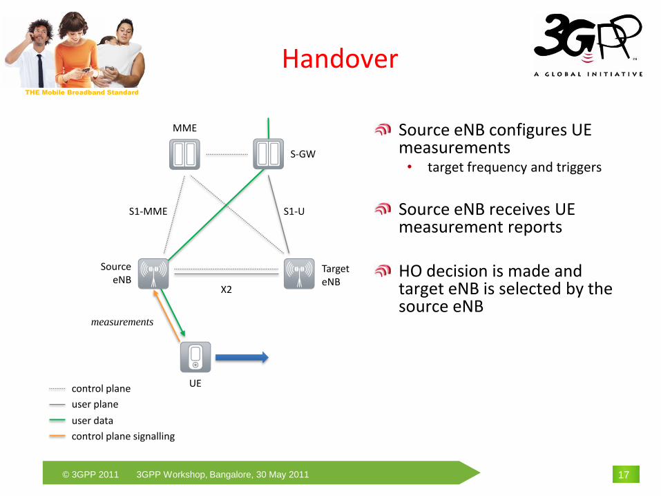
Handover
17
SourceeNB
TargeteNB
UE
X2
S-GW
MME
control plane
user plane
user data
S1-US1-MME
control plane signalling
measurements
Source eNB configures UE measurements• target frequency and triggers
Source eNB receives UE measurement reports
HO decision is made and target eNB is selected by the source eNB

THE Mobile Broadband Standard
© 3GPP 2011 3GPP Workshop, Bangalore, 30 May 2011
HO request sent from source eNB to target eNB
Target eNB performs admission control and accepts the HO request
HO Ack sent to source eNB from target eNB
Handover
18
SourceeNB
TargeteNB
UE
S-GW
MME
control plane
user plane
user data
S1-US1-MME
control plane signalling
measurements
HO request
HO Request Ack

THE Mobile Broadband Standard
© 3GPP 2011 3GPP Workshop, Bangalore, 30 May 2011
Handover
19
SourceeNB
TargeteNB
UE
X2
S-GW
MME
control plane
user plane
user data
S1-US1-MME
control plane signalling
HO command
HO command is sent to the UE• RRCConnectionReconfiguration
including the mobilityControlInfo
Data forwarding initiated towards the target eNB

THE Mobile Broadband Standard
© 3GPP 2011 3GPP Workshop, Bangalore, 30 May 2011
Handover
20
SourceeNB
TargeteNB
UE
X2
S-GW
MME
control plane
user plane
user data
S1-US1-MME
control plane signalling
HO confirm
UE accesses the target eNB and confirms the HO• RACH procedure is initiated• RRCConnectionReconfigurationCo
mplete is sent

THE Mobile Broadband Standard
© 3GPP 2011 3GPP Workshop, Bangalore, 30 May 2011
Handover
21
SourceeNB
TargeteNB
UE
X2
S-GW
MME
control plane
user plane
user data
control plane signalling
Target eNB requests EPC to switch the data path• eNB → MME : path switch
request • MME → S-GW : modify bearer
request• S-GW → MME : modify bearer
response• MME → eNB : path switch
request ACK
Target eNB notifies the source eNB that UE resources can be released

THE Mobile Broadband Standard
© 3GPP 2011 3GPP Workshop, Bangalore, 30 May 2011
Handover
22
SourceeNB
TargeteNB
X2
S-GW
MME
control plane
user plane
user data
S1-US1-MME
control plane signalling
Path is switched
Source eNB finishes forwarding packets• once completed UE context can
be cleared and resources freed
HO is completed
UE
THE Mobile Broadband Standard
© 3GPP 2011 3GPP Workshop, Bangalore, 30 May 2011
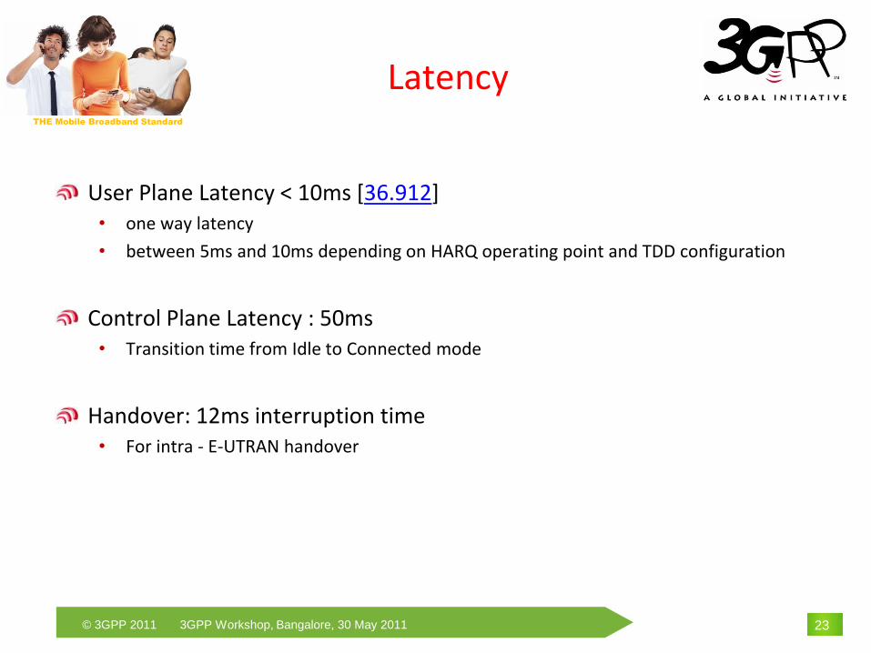
Latency
User Plane Latency < 10ms [36.912]• one way latency
• between 5ms and 10ms depending on HARQ operating point and TDD configuration
Control Plane Latency : 50ms• Transition time from Idle to Connected mode
Handover: 12ms interruption time• For intra - E-UTRAN handover
23

THE Mobile Broadband Standard
© 3GPP 2011 3GPP Workshop, Bangalore, 30 May 2011
Rel-10
Overview
Carrier Aggregation
Minimisation of Drive Tests
24

THE Mobile Broadband Standard
© 3GPP 2011 3GPP Workshop, Bangalore, 30 May 2011
Rel-10
Main goal of Rel-10 was to fulfil the IMT-Advanced requirements• up to 1Gbps in downlink and 500Mbps in uplink [36.913]
• took 2 years of efforts in 3GPP
Main Rel-10 Features• Carrier Aggregation: to increase the bit rate and reach IMT-A requirements [WID]
• eICIC: to efficiently support highly increasingly complex network deployment scenarios with unbalanced transmit power nodes sharing the same frequency [WID]
• Relay Nodes: to improve the coverage of high data rates, cell-edge throughput and ease temporary network deployments [WID]
• Minimisation of Drive Tests / SON Enhancements: enhanced and combined effort to optimize the performance of the network aiming to automate the collection of UE measurements and thus minimize the need for operators to rely on manual drive-tests [WID] [WID]
• MBMS enhancements: to enable the network to know the reception status of UEs receiving a given MBMS service in connected mode… [WID]
• Machine Type Communication: protect the core network from signalling congestion & overload [WID]
25

THE Mobile Broadband Standard
© 3GPP 2011 3GPP Workshop, Bangalore, 30 May 2011
Carrier Aggregation
Goal of Carrier aggregation is to aggregate Rel-8 compatible carriers to increase peak data rate• up to 5 carriers can be aggregated in DL for a maximum BW of 100 MHz
• non-contiguous carriers can also be aggregated in DL for increased flexibility
26
LTE-Advanced maximum bandwidth
Carrier 1 Carrier 4 Carrier 5Carrier 3Carrier 2
Rel’8 BW Rel’8 BW Rel’8 BW Rel’8 BW Rel’8 BW

THE Mobile Broadband Standard
© 3GPP 2011 3GPP Workshop, Bangalore, 30 May 2011
Carrier Aggregation
Impact on L2 Architecture
27
HARQ HARQ
DL-SCH
on CC1
...
Segm.
ARQ etc
Multiplexing UE1 Multiplexing UEn
BCCH PCCH
Unicast Scheduling / Priority Handling
Logical Channels
MAC
Radio Bearers
Security Security...
CCCH
MCCH
Multiplexing
MTCH
MBMS Scheduling
PCHBCH MCH
RLC
PDCP
ROHC ROHC...
Segm.
ARQ etc...
Transport Channels
Segm.
ARQ etc
Security Security...
ROHC ROHC...
Segm.
ARQ etc...
Segm. Segm.
...
...
...
DL-SCH
on CCx
HARQ HARQ
DL-SCH
on CC1
...
There is one PDCP and RLC per Radio Bearer. Not visible from RLC
on how many CCs the PHY layer transmission is conducted.
Dynamic L2 packet scheduling across multiple CCs supported
Independent HARQ per CC. HARQ retransmissions shall be sent on the
same CC as the CC of the original transmission
Separate TrCH per CC
THE Mobile Broadband Standard
© 3GPP 2011 3GPP Workshop, Bangalore, 30 May 2011
Carrier Aggregation
Basic Concept• when CA is configured, the UE only has one RRC connection with the network
• at RRC connection establishment/re-establishment/handover, one serving cell provides the NAS mobility information (e.g. TAI), and at RRC connection re-establishment/handover, one serving cell provides the security input
• this cell is referred to as the Primary Cell (PCell)
• in the downlink, the carrier corresponding to the PCell is the Downlink Primary Component Carrier (DL PCC) while in the uplink it is the Uplink Primary Component Carrier (UL PCC)
• depending on UE capabilities, Secondary Cells (SCells) can be configured to form together with the PCell a set of serving cells
• in the downlink, the carrier corresponding to an SCell is a Downlink Secondary Component Carrier (DL SCC) while in the uplink it is an Uplink Secondary Component Carrier (UL SCC)
• the configured set of serving cells for a UE therefore always consists of one PCell and one or more SCells
28
THE Mobile Broadband Standard
© 3GPP 2011 3GPP Workshop, Bangalore, 30 May 2011
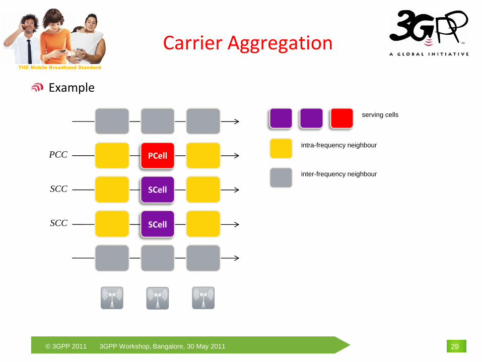
Carrier Aggregation
Example
29
PCell
SCell
SCell
serving cells
intra-frequency neighbour
inter-frequency neighbour
PCC
SCC
SCC

THE Mobile Broadband Standard
© 3GPP 2011 3GPP Workshop, Bangalore, 30 May 2011
Minimisation of Drive Tests
Goal of Minimisation of Drive Tests• replace manual drive testing that the operators have to perform currently
• automatic UE measurements and data logging in drive-tests scenarios
• provide a basis for finding coverage problems in the HSPA & LTE network
30
THE Mobile Broadband Standard
© 3GPP 2011 3GPP Workshop, Bangalore, 30 May 2011
Minimisation of Drive Tests
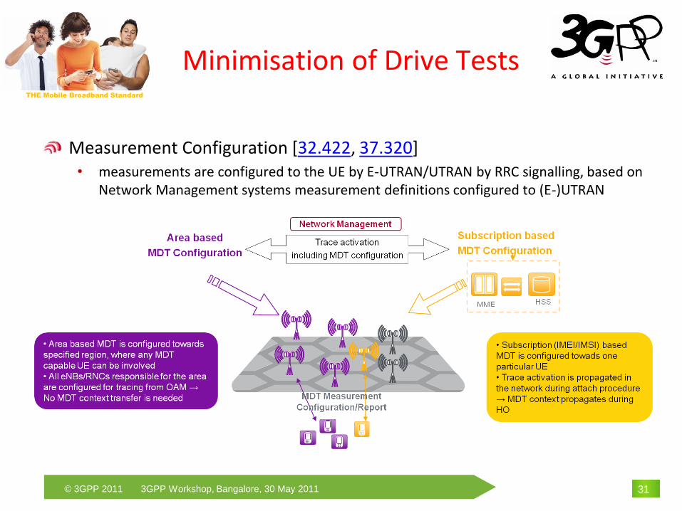
Measurement Configuration [32.422, 37.320]• measurements are configured to the UE by E-UTRAN/UTRAN by RRC signalling, based on
Network Management systems measurement definitions configured to (E-)UTRAN
31

THE Mobile Broadband Standard
© 3GPP 2011 3GPP Workshop, Bangalore, 30 May 2011
Minimisation of Drive Tests
Measurements• Real time (Immediate MDT) and non-real time (Logged MDT) measurements
• Measurements are configured to the UE by (E-)UTRAN by dedicated RRC signalling
• The measurements should be tagged with UE position on best effort basis• in the best case GNSS information can be included,
• otherwise cell ID or RF fingerprints
32

THE Mobile Broadband Standard
© 3GPP 2011 3GPP Workshop, Bangalore, 30 May 2011
Minimisation of Drive Tests
RLF Reporting• To identify origin of radio link failures
• Content• Cell measurement results at the time of the failure
• Available accurate location information
• Cell IDs for following cells
• E-CGI or PCI where the failure happened
• E-CGI of the cell to which UE attempted establish the connection after the failure
• Time between last successful HO and the failure
• Reporting• At RRC Connection Setup, Re-establishment or Reconfiguration
• UE Information procedure is used
• upon retrieval report is removed, otherwise should be maintainedin the UE for 48hours
33

THE Mobile Broadband Standard
© 3GPP 2011 3GPP Workshop, Bangalore, 30 May 2011
Conclusions
34

THE Mobile Broadband Standard
© 3GPP 2011 3GPP Workshop, Bangalore, 30 May 2011 35
Conclusions
E-UTRAN presents a flat architecture for low latency and delays
E-UTRAN Rel-10 introduces• carrier aggregation for higher bit rates and flexible spectrum usage
• eICIC for improved support of HetNet
• RN to increase coverage and deployment flexibility
• MDT/SON to ease deployments and network optimisations

THE Mobile Broadband Standard
© 3GPP 2011 3GPP Workshop, Bangalore, 30 May 2011
Thank You
36
www.3gpp.org
More Information about 3GPP:
Benoist SébireNokia Siemens [email protected]