Radical Service Manual Rev D -...
37
i Radical Signal Extraction Pulse Oximeter Service Manual UM-10014 - 0804 Signal Extraction Pulse Oximeter Service Manual Masimo Corporation
Transcript of Radical Service Manual Rev D -...
i Radical Signal Extraction Pulse Oximeter Service Manual
UM-10014 - 0804
Signal Extraction Pulse Oximeter
Service Manual
Masimo Corporation
Radical Signal Extraction Pulse Oximeter Service Manual UM-10014 – 0804
ii
The Radical Service Manual is intended to provide the necessary information for proper servicing of all models of the Radical pulse oximetry system. This manual is structured to support troubleshooting to the assembly or module level. This manual does not provide instructions for troubleshooting to the printed circuit board component level. There may be information provided in this manual that is not relevant for your system. Do not service the Radical pulse oximeter without completely reading and understanding these instructions. Service training provided by Masimo is required prior to utilization of this manual. CAUTION:
Federal law (U.S.) restricts this device to sale by or on the order of a physician
Masimo Corporation 40 Parker
Irvine, CA 92618 USA
Tel: 949-297-7000 Fax:949-297-7001 www.masimo.com
Authorized Representative:
MDSS GmbH Burckhardstrasse 1 D-30163 Hanover
Germany Tel: +49-511-62 62 86 30 Fax:+49-511-62 62 86 33
Made in USA. © 2004 Masimo Corporation. All rights reserved. Masimo, Masimo Logo, SET, LNOP, Radical, Rad-9, Rad-5, SIQ, FastSat, FastStart Signal IQ and APOD are trademarks of Masimo Corporation. Covered by one or more of the following U.S. Patents: RE38,492, RE38,476, 6,699,194, 6,684,090, 6,658,276, 6,654,624, 6,650,917, 6,643,530, 6,606,511, 6,584,336, 6,501,975, 6,463,311, 6,430,525, 6,360,114, 6,263,222, 6,236,872, 6,229,856, 6,206,830, 6,157,850, 6,067,462, 6,011,986, 6,002,952, 5,919,134, 5,823,950, 5,769,785, 5,758,644, 5,685,299, 5,632,272, 5,490,505, 5,482,036, international equivalents, or one or more of the patents referenced at www.masimo.com/patents. Other patents pending.
Radical Signal Extraction Pulse Oximeter Service Manual UM-10014 – 0804
iii
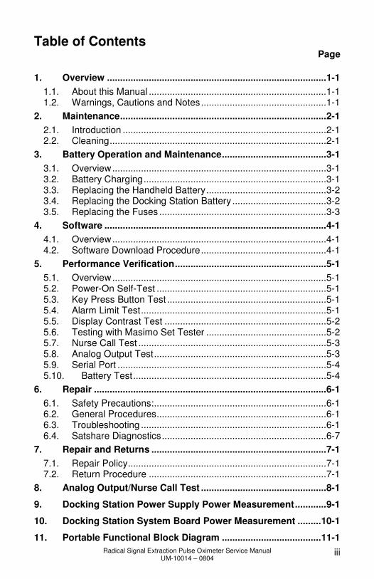
Table of Contents Page
1. Overview ....................................................................................1-1
1.1. About this Manual ....................................................................1-1 1.2. Warnings, Cautions and Notes................................................1-1
2. Maintenance...............................................................................2-1
2.1. Introduction ..............................................................................2-1 2.2. Cleaning...................................................................................2-1
3. Battery Operation and Maintenance........................................3-1
3.1. Overview..................................................................................3-1 3.2. Battery Charging......................................................................3-1 3.3. Replacing the Handheld Battery..............................................3-2 3.4. Replacing the Docking Station Battery ....................................3-2 3.5. Replacing the Fuses ................................................................3-3
4. Software .....................................................................................4-1
4.1. Overview..................................................................................4-1 4.2. Software Download Procedure................................................4-1
5. Performance Verification..........................................................5-1
5.1. Overview..................................................................................5-1 5.2. Power-On Self-Test .................................................................5-1 5.3. Key Press Button Test .............................................................5-1 5.4. Alarm Limit Test.......................................................................5-1 5.5. Display Contrast Test ..............................................................5-2 5.6. Testing with Masimo Set Tester ..............................................5-2 5.7. Nurse Call Test ........................................................................5-3 5.8. Analog Output Test..................................................................5-3 5.9. Serial Port ................................................................................5-4 5.10. Battery Test..........................................................................5-4
6. Repair .........................................................................................6-1
6.1. Safety Precautions:..................................................................6-1 6.2. General Procedures.................................................................6-1 6.3. Troubleshooting .......................................................................6-1 6.4. Satshare Diagnostics...............................................................6-7
7. Repair and Returns ...................................................................7-1
7.1. Repair Policy............................................................................7-1 7.2. Return Procedure ....................................................................7-1
8. Analog Output/Nurse Call Test ................................................8-1
9. Docking Station Power Supply Power Measurement............9-1
10. Docking Station System Board Power Measurement .........10-1
11. Portable Functional Block Diagram ......................................11-1
Radical Signal Extraction Pulse Oximeter Service Manual UM-10014 – 0804
iv
12. Docking Station Functional Block Diagram .........................12-2
13. Radical Isolation Block Diagram ...........................................13-1
14. Portable Wiring Interconnect .................................................14-1
15. Docking Station Wiring Interconnect ....................................15-1
16. Portable Parts List...................................................................16-1
17. Docking Station Parts List .....................................................17-1
18. RDS2 Parts List .......................................................................18-1
Disks
FRM-1312 (Back Cover)

Radical Signal Extraction Pulse Oximeter Service Manual UM-10014 – 0804
1-1
1. Overview
1.1. About this Manual
This manual explains how to service the Radical pulse oximeter. Important safety information relating to general use of the Radical pulse oximeter appears in the Radical Operator’s Manual. Other important safety information is located throughout this manual where appropriate.
1.2. Warnings, Cautions and Notes
Please read and follow any warnings, cautions and notes presented throughout this manual. An explanation of these labels is as follows: A warning is provided when actions may result in a serious outcome (i.e., injury, serious adverse affect, death) to the patient or user. Look for text in a gray shaded box. Sample of Warning:
WARNING: THIS IS A SAMPLE OF A WARNING STATEMENT.
A caution is given when any special care is to be exercised by the patient or user to avoid injury to the patient, damage to this device or damage to other property. Sample of Caution:
CAUTION: This is a sample of a Caution statement.
A note is provided when extra general information is applicable. Sample of Note:
Note: This is a sample of a Note statement.
Radical Signal Extraction Pulse Oximeter Service Manual UM-10014 – 0804
2-1
2. Maintenance
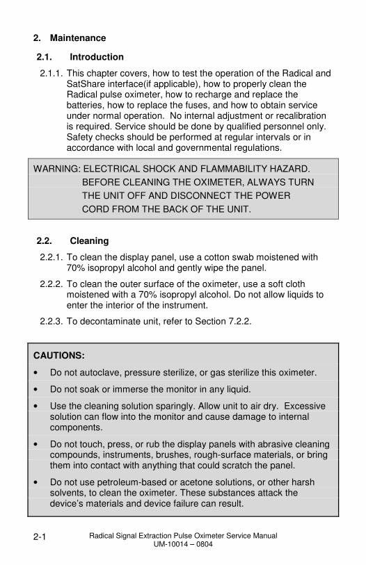
2.1. Introduction
2.1.1. This chapter covers, how to test the operation of the Radical and SatShare interface(if applicable), how to properly clean the Radical pulse oximeter, how to recharge and replace the batteries, how to replace the fuses, and how to obtain service under normal operation. No internal adjustment or recalibration is required. Service should be done by qualified personnel only. Safety checks should be performed at regular intervals or in accordance with local and governmental regulations.
WARNING: ELECTRICAL SHOCK AND FLAMMABILITY HAZARD.
BEFORE CLEANING THE OXIMETER, ALWAYS TURN
THE UNIT OFF AND DISCONNECT THE POWER
CORD FROM THE BACK OF THE UNIT.
2.2. Cleaning
2.2.1. To clean the display panel, use a cotton swab moistened with 70% isopropyl alcohol and gently wipe the panel.
2.2.2. To clean the outer surface of the oximeter, use a soft cloth moistened with a 70% isopropyl alcohol. Do not allow liquids to enter the interior of the instrument.
2.2.3. To decontaminate unit, refer to Section 7.2.2.
CAUTIONS:
• Do not autoclave, pressure sterilize, or gas sterilize this oximeter.
• Do not soak or immerse the monitor in any liquid.
• Use the cleaning solution sparingly. Allow unit to air dry. Excessive solution can flow into the monitor and cause damage to internal components.
• Do not touch, press, or rub the display panels with abrasive cleaning compounds, instruments, brushes, rough-surface materials, or bring them into contact with anything that could scratch the panel.
• Do not use petroleum-based or acetone solutions, or other harsh solvents, to clean the oximeter. These substances attack the device’s materials and device failure can result.
Radical Signal Extraction Pulse Oximeter Service Manual UM-10014 – 0804
3-1
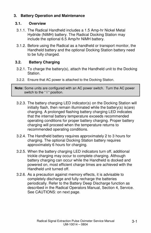
3. Battery Operation and Maintenance
3.1. Overview
3.1.1. The Radical Handheld includes a 1.5 Amp-hr Nickel Metal Hydride (NiMH) battery. The Radical Docking Station may include the optional 6.5 Amp/hr NiMH battery.
3.1.2. Before using the Radical as a handheld or transport monitor, the Handheld battery and the optional Docking Station battery need to be fully charged.
3.2. Battery Charging
3.2.1. To charge the battery(s), attach the Handheld unit to the Docking Station.
3.2.2. Ensure that AC power is attached to the Docking Station.
Note: Some units are configured with an AC power switch. Turn the AC power
switch to the “ I “ position.
3.2.3. The battery charging LED indicator(s) on the Docking Station will
initially flash, then remain illuminated while the battery(s) is(are) charging. A prolonged flashing battery charging LED indicates that the internal battery temperature exceeds recommended operating conditions for proper battery charging. Proper battery charging will proceed when the temperature returns to recommended operating conditions.
3.2.4. The Handheld battery requires approximately 2 to 3 hours for charging. The optional Docking Station battery requires approximately 6 hours for charging.
3.2.5. When the battery charging LED indicators turn off, additional trickle charging may occur to complete charging. Although battery charging can occur while the Handheld is docked and powered on, most efficient charge times are achieved with the Handheld unit turned off.
3.2.6. As a precaution against memory effects, it is advisable to completely discharge and fully recharge the batteries periodically. Refer to the Battery Deep Discharge function as described in the Radical Operators Manual, Section 4, Service. See CAUTIONS: on next page.

Radical Signal Extraction Pulse Oximeter Service Manual UM-10014 – 0804
3-2
CAUTIONS:
• If the Radical has not been charged for 1 month or more, then recharge the battery prior to use.
• At low battery warning, connect the Radical to AC power to prevent interruption of power.
• Additional information on the Radical batteries may be found in the Radical Operators Manual.
3.3. Replacing the Handheld Battery
3.3.1. Turn the Radical Handheld off and remove the patient cable connection. Detach the Radical Handheld from the Docking Station (if docked).
3.3.2. Place the Handheld face down on a soft surface such that no cosmetic damage occurs to the unit.
3.3.3. Loosen the closure screw on the battery and remove the battery.
3.3.4. Position the replacement battery into the Handheld, bottom first.
3.3.5. Tighten the battery screw until it is secure and the grasp loop is pointing towards the top of the Handheld and lays flat into the plastic housing.
3.3.6. Place Handheld into Docking Station. Turn on power and if necessary, charge battery according to Section 9 of the Radical Operator’s Manual: Battery Operation and Maintenance.
3.4. Replacing the Docking Station Battery
CAUTION: Do not over tighten screws. Tighten the screws throughout the Radical Handheld and Docking Station to 80 in.- oz.
Note: Docking Station Battery can only be installed in RDS-1B type units.
Note: It will be necessary to perform safety testing after replacement.
3.4.1. With the AC power cord disconnected, remove the Handheld from the Docking Station.
Radical Signal Extraction Pulse Oximeter Service Manual UM-10014 – 0804
3-3
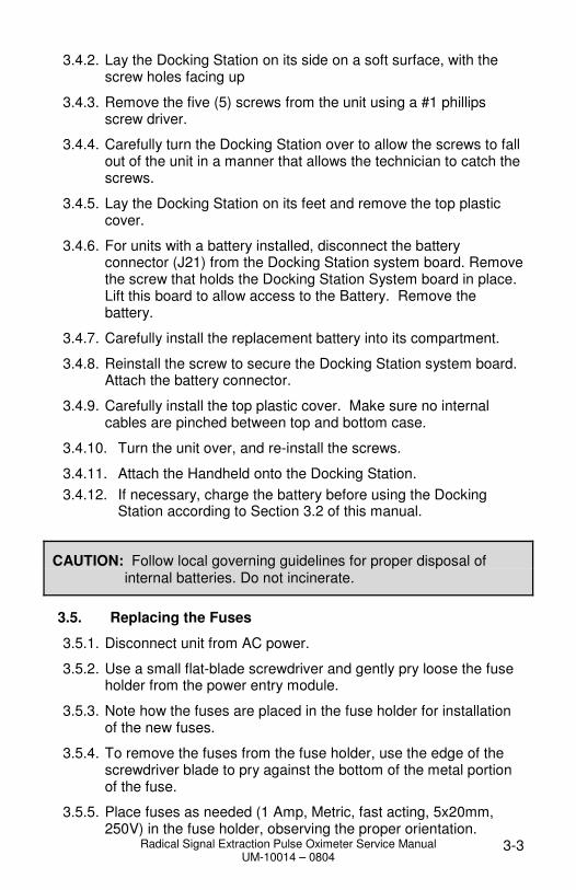
3.4.2. Lay the Docking Station on its side on a soft surface, with the screw holes facing up
3.4.3. Remove the five (5) screws from the unit using a #1 phillips screw driver.
3.4.4. Carefully turn the Docking Station over to allow the screws to fall out of the unit in a manner that allows the technician to catch the screws.
3.4.5. Lay the Docking Station on its feet and remove the top plastic cover.
3.4.6. For units with a battery installed, disconnect the battery connector (J21) from the Docking Station system board. Remove the screw that holds the Docking Station System board in place. Lift this board to allow access to the Battery. Remove the battery.
3.4.7. Carefully install the replacement battery into its compartment.
3.4.8. Reinstall the screw to secure the Docking Station system board. Attach the battery connector.
3.4.9. Carefully install the top plastic cover. Make sure no internal cables are pinched between top and bottom case.
3.4.10. Turn the unit over, and re-install the screws.
3.4.11. Attach the Handheld onto the Docking Station.
3.4.12. If necessary, charge the battery before using the Docking Station according to Section 3.2 of this manual.
CAUTION: Follow local governing guidelines for proper disposal of internal batteries. Do not incinerate.
3.5. Replacing the Fuses
3.5.1. Disconnect unit from AC power.
3.5.2. Use a small flat-blade screwdriver and gently pry loose the fuse holder from the power entry module.
3.5.3. Note how the fuses are placed in the fuse holder for installation of the new fuses.
3.5.4. To remove the fuses from the fuse holder, use the edge of the screwdriver blade to pry against the bottom of the metal portion of the fuse.
3.5.5. Place fuses as needed (1 Amp, Metric, fast acting, 5x20mm, 250V) in the fuse holder, observing the proper orientation.
Radical Signal Extraction Pulse Oximeter Service Manual UM-10014 – 0804
3-4
3.5.6. Slide the fuse holder back into the power entry module and press firmly to make sure it is firmly inserted.
3.5.7. The unit is ready to be reconnected to AC power.
Note: If the fuses blow after replacement, troubleshoot the unit.
WARNING: FIRE HAZARD: TO PROTECT AGAINST FIRE HAZARD, REPLACE ONLY WITH FUSES OF THE SAME TYPE, CURRENT RATING, AND VOLTAGE RATING.

Radical Signal Extraction Pulse Oximeter Service Manual UM-10014 – 0804
4-1
4. Software
4.1. Overview
4.1.1. The Radical product is configured to allow software downloads directly from a PC. The Radical product has three different boards that utilize software that may require upgrade. The Pulse Oximeter Board, Handheld System Board and Docking Station System Board all operate with software that is independent of each other. The software must be compatible between the boards for the Radical product to operate properly. The boards communicate with each other through on board connections - in the case of the Oximeter Board to Handheld System Board. For the Handheld to Docking Station communication, this is accomplished through a Contact Pin/Interface Cable.
4.1.2. When software upgrades are affected, it is imperative that FRM-1312 is completed and returned to Masimo to ensure each unit is tracked with the software version of each unit. This form can be found in this manual, in the contents of the software disk and can also be acquired from Masimo if necessary by contacting Masimo using the information in Section 7.2.11.
4.2. Software Download Procedure
Note: RDS-2 does not require programming.
4.2.1. On the PC, open FlashApp.exe from your hard drive. Masimo software can be obtained by Authorized Service providers by calling Masimo Technical Support “domestic” at (800)326-4890, option #2, or “International” at 949-297-7498 option #2.
4.2.2. Set the default “Target”, “Port” and “Baud” parameters as shown in the table below.
FlashApp Number
Target Port Baud1
FlashApp #1 Portable COM1 57600
FlashApp #2 Portable (MS-3) (MS-5) (MS-7) (MS-11) COM1 57600
FlashApp #3 Docking Station COM1 57600
4.2.3. For programming Radical Handheld, perform the following steps:
1 If a unit does not program with 57600, set baud rate to 9600.

Radical Signal Extraction Pulse Oximeter Service Manual UM-10014 – 0804
4-2
4.2.4. Connect a Docking Station to AC outlet and turn the AC Switch to ON (if applicable).
4.2.5. Connect a straight through serial cable between the PC and the Docking Station.
4.2.6. Install the Radical Handheld to the Docking Station.
4.2.7. Turn off the Handheld, if it is on.
4.2.8. Press the green button on the FlashApp window with Target set to Portable (Green) or Portable (Blue) depending on the LCD color.
4.2.9. Turn on the Handheld.
4.2.10. The green button will turn off, and red button will turn on. Wait until the green button turns on again.
4.2.11. If the message on the Status window is “Complete – Success”, continue with the next step. If programming is not successful, go back to 4.2.7 and repeat. If this cycle is repeated 3 times without success, troubleshooting is required.
4.2.12. Turn off the Handheld.
4.2.13. To program the Oximeter board, perform the following steps:
Note: The serial number label will indicate which version Oximeter board is inside. (MS-3 is identified by not having an indicator).
4.2.14. Press the green button on FlashApp window with Target set to Portable MS-3, MS-5, MS-7or MS-11. The MS-# board type can be determined by looking at the bar code label on the lower back side of the Radical handheld. The MS-# board type is listed to the left of the bar code. If the MS-3L board is present, there is no MS- # board type listed.
4.2.15. Turn on the Handheld.
4.2.16. The green button will turn off, and red button will turn on. Wait until the green button turns on again.
4.2.17. If the message on the Status window is “Complete – Success”, continue with next step. If programming is not successful, go back to 4.2.12 and repeat. If this cycle is repeated 3 times without success, troubleshooting is required.

Radical Signal Extraction Pulse Oximeter Service Manual UM-10014 – 0804
4-3
4.2.18. To program Radical Docking Station, perform the following steps:
4.2.19. Connect a Docking Station to AC outlet and turn the switch to ON position (if applicable).
4.2.20. Connect a serial cable between computer and the Docking Station.
4.2.21. Install a known good Radical Handheld to the Docking Station.
4.2.22. Turn off the Handheld, if it is on.
4.2.23. Press the green button on FlashApp window with Target set to Docking Station.
4.2.24. Turn on the Handheld.
4.2.25. The green button will turn off, and red button will turn on. Wait until the green button turns on again.
4.2.26. If the message on the Status window is “Complete – Success”, continue with next step. If the message is “Complete – Fail”, go back to 4.2.22 and repeat. If this cycle is repeated 3 times without success, troubleshooting is required.
4.2.27. To check software version numbers, perform the following steps:
4.2.28. Turn off the Handheld.
4.2.29. Turn on the Handheld.
4.2.30. Press the Menu key.
4.2.31. Press the Down key and select About.
4.2.32. Verify that the Handheld (Handheld, Masimo SET) and Docking Station (D-Station) software version(s) are the intended version. The Handheld must be docked to the Docking Station in order to see the version of the Docking Station.
4.2.33. Record software version in FRM-1312 and notify Masimo as per Section 4.1.2.
Radical Signal Extraction Pulse Oximeter Service Manual UM-10014 – 0804
5-1
5. Performance Verification
5.1. Overview
5.1.1. To test the performance of the Radical pulse oximeter following repairs or during routine maintenance, follow the procedure outlined in this section. If the Radical fails any of the described tests, discontinue its use and correct the problem before returning the unit back to the user.
5.1.2. Before performing the following tests place the Radical Handheld into the Docking Station, connect the Radical to AC power and fully charge the Radical Handheld battery (the AC mains switch must be on). Disconnect any patient cables or pulse oximetry probes, as well as SatShare, serial or Analog Output/Nurse Call cables from the instrument.
5.2. Power-On Self-Test
5.2.1. Connect the unit to AC power and verify that the AC Power Indicator LED is illuminated. If it is not, verify that the AC mains switch is on.
5.2.2. Turn the unit on by depressing the Power/Standby Button. Within 5 seconds all available LEDs are momentarily illuminated, a 1-second beep tone sounds, and the Masimo SET logo is displayed.
5.2.3. The Docking Indicator LED, AC Power Indicator LED, Handheld Battery Charge LED and Docking Station Charge LED (if Docking Station is equipped with optional battery) are illuminated and the Radical begins normal operation.
5.3. Key Press Button Test
5.3.1. With the exception of the Power/Standby Button, press each soft key button and verify that the Radical acknowledges each key-press with an audible beep tone or by indicating an associated change on the display.
5.4. Alarm Limit Test
5.4.1. With the monitor turned on, select the Menu Access key and enter the Alarm menu. Change the desired parameter, below, to a value two points below the currently selected value, and accept the change.
5.4.2. Verify that the newly set parameter is shown on the Saturation Alarm Limit Display, next to the SpO2 or pulse rate measurement display.
5.4.3. Return the Alarm parameter to its original setting.
Radical Signal Extraction Pulse Oximeter Service Manual UM-10014 – 0804
5-2
5.4.4. Perform steps 5.4.1 through 5.4.3 with the High Saturation Alarm parameter.
5.4.5. Perform steps 5.4.1 through 5.4.3 with the Low Saturation Alarm parameter.
5.4.6. Perform steps 5.4.1 through 5.4.3 with the High Pulse Rate Alarm parameter.
5.4.7. Perform steps 5.4.1 through 5.4.3 with the Low Pulse Rate Alarm parameter.
5.4.8. Reset the alarm limits again to the original settings.
5.5. Display Contrast Test
5.5.1. With the monitor turned on, select the Menu key and enter the Display menu. Change the Contrast parameter by scrolling through the contrast settings.
5.5.2. Return the Contrast setting to the original value, or a value that allows maximum viewing contrast.
5.5.3. Exit the Menu system and press and hold down the Backlight/Contrast button for several seconds. The display will scroll again through all the contrast settings.
5.5.4. Release the Backlight/Contrast button again when the display shows maximum viewing contrast.
5.6. Testing with Masimo Set Tester
5.6.1. Turn the Radical off and then on again.
5.6.2. Set the alarm limits to:
% SpO2 Pulse Rate
High 100 140
Low 90 50
5.6.3. Connect the Masimo Tester to the Radical.
5.6.4. Verify that within 20 seconds a plethysmographic and a Signal IQ waveform displays.
5.6.5. Verify that the SpO2 measurement is between 79% and 84%.
5.6.6. Verify that the pulse rate measurement is between 55 bpm and 65 bpm.
Radical Signal Extraction Pulse Oximeter Service Manual UM-10014 – 0804
5-3
5.6.7. Verify that an audible alarm occurs and that the SpO2 measurement and the low SpO2 alarm are flashing
5.6.8. Press the Alarm Silence button once and verify that the alarm is silenced.
5.6.9. Wait 120 seconds and verify that the alarm silence times out and the audible alarm is activated again. Disable the Alarm before continuing.
5.6.10. Press the Increase Loudness button several times and verify that the loudness of the pulse beep tone increases.
5.6.11. Press the Decrease Loudness button and verify that the loudness of the pulse beep tone decreases. Press the Decrease Loudness button and verify that the loudness of the pulse beep tone can be turned off.
5.7. Nurse Call Test
Note: Refer to Section 8 in this manual for connector pinouts noted in Sections 5.7and 5.8.
5.7.1. Disconnect the patient cable or the Masimo SET Tester from the Radical and turn the instrument on. Ensure that there are no audible alarms and that the audible alarms are not silenced.
5.7.2. Connect the common lead of a digital multimeter to pin 12 (Nurse Call - Common) of the Analog Output/Nurse Call Connector (see Service Manual, Troubleshooting, Section 8, Analog Output/Nurse Call Test) on the Radical. Connect the positive lead of the multimeter to pin 6 (Nurse Call - Normally Open) of the Analog Output/Nurse Call Connector and
measure that the resistance is greater than 1 MΩ (open circuit).
5.7.3. Trigger an alarm on the monitor (e.g. by disconnecting a sensor after it was measuring data) and verify the resistance is
< 20Ω.
5.8. Analog Output Test
5.8.1. Disconnect all patient cables and sensors from the Radical. Turn the Radical off and then on again.
5.8.2. Connect the common lead of a multimeter to the pin 2 (Ground) of the Analog Output/Nurse Call Connector. Connect the positive lead of the multimeter to pin 9 (Analog 1) of Analog Output/Nurse Call Connector.

Radical Signal Extraction Pulse Oximeter Service Manual UM-10014 – 0804
5-4
5.8.3. Enter the menu system and set the "Output", "Analog 1" to "0v Output". Verify that the voltmeter measures a voltage of approximately between –10mV and 100mV.
5.8.4. Set “Analog 1” to 1v Output”. Verify that the voltmeter measures a voltage between 0.90V to 1.10V.
5.8.5. Reset “Analog1” to “Spo2 0 – 100%”.
5.8.6. Repeat steps 5.8.3 and 5.8.4 with the positive lead of the multimeter connected to pin 15 (Analog2) and set “Analog2” to “0V Output” and “1V Output”.
5.8.7. Reset “Analog2” to “Pulse Rate”.
5.9. Serial Port
5.9.1. The serial port outputs ASCII data using standard RS-232 protocol via a straight through serial cable. The Handheld must be docked with AC power applied.
5.9.2. Validation of the port can be done by connecting a serial printer or using a PC with Hyper Terminal and the following setup:
5.9.3. Communication Parameters
baud rate 9600 bps
data bits 8
stop bit 1
parity none
hand shaking none
5.9.4. With the Radical connected as per the above setup, attach a patient cable and sensor to the Radical. From the Output menu, select ASCII 1 and the printer (or PC monitor) will print in the following format every second.
12/11/00 11:56:29 SPO2=100% BPM=240 PI=20.00% ALARM=00 EXC=820\r\n
5.10. Battery Test
5.10.1. Fully charge the Radical Handheld Battery by placing the Handheld into the Docking Station and connecting the AC power (the AC mains switch must be on).
5.10.2. Verify that the green Handheld Battery Indicator LED is illuminated.
5.10.3. When the Radical is fully charged the green Handheld Battery Indicator turns off.

Radical Signal Extraction Pulse Oximeter Service Manual UM-10014 – 0804
5-5
5.10.4. Turn the Radical on and verify that the Handheld Battery indicator shows a full charge.
5.10.5. Fully charge the Radical Docking Station Battery by placing the Handheld into the Docking Station and connecting the AC power (the AC mains switch must be on).
5.10.6. Verify that the green Docking Station Battery Indicator LED is illuminated.
5.10.7. When the Radical is fully charged the green Docking Station Battery Indicator turns off.
5.10.8. Turn the Radical on and verify that the Docking Station Battery indicator shows a full charge.
Radical Signal Extraction Pulse Oximeter Service Manual UM-10014 – 0804
6-1
6. Repair
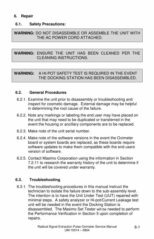
6.1. Safety Precautions:
WARNING: DO NOT DISASSEMBLE OR ASSEMBLE THE UNIT WITH THE AC POWER CORD ATTACHED.
WARNING: ENSURE THE UNIT HAS BEEN CLEANED PER THE CLEANING INSTRUCTIONS.
WARNING: A HI-POT SAFETY TEST IS REQUIRED IN THE EVENT THE DOCKING STATION HAS BEEN DISASSEMBLED.
6.2. General Procedures
6.2.1. Examine the unit prior to disassembly or troubleshooting and inspect for cosmetic damage. External damage may be helpful in determining the root cause of the failure.
6.2.2. Note any markings or labeling the end user may have placed on the unit that may need to be duplicated or transferred in the event the housing or ancillary components are to be replaced.
6.2.3. Make note of the unit serial number.
6.2.4. Make note of the software versions in the event the Oximeter board or system boards are replaced, as these boards require software updates to make them compatible with the end users version of software.
6.2.5. Contact Masimo Corporation using the information in Section 7.2.11 to research the warranty history of the unit to determine if the unit will be covered under warranty.
6.3. Troubleshooting
6.3.1. The troubleshooting procedures in this manual instruct the technician to isolate the failure down to the sub-assembly level. The intention is to have the Unit Under Test (UUT) repaired with minimal steps. A safety analyzer or Hi-pot/Current Leakage test unit will be needed in the event the Docking Station is disassembled. The Masimo Set Tester will be needed to perform the Performance Verification in Section 5 upon completion of repairs.
Radical Signal Extraction Pulse Oximeter Service Manual UM-10014 – 0804
6-2
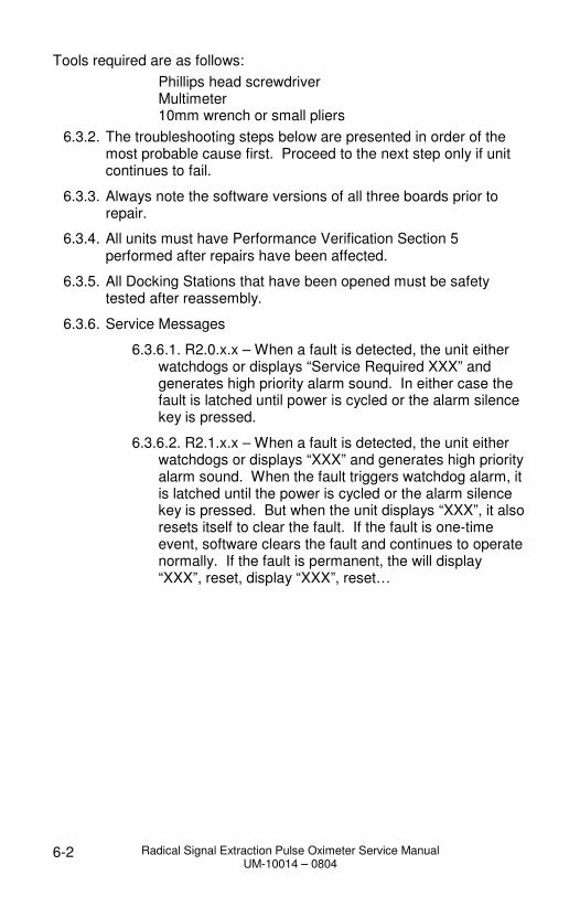
Tools required are as follows:
Phillips head screwdriver Multimeter 10mm wrench or small pliers
6.3.2. The troubleshooting steps below are presented in order of the most probable cause first. Proceed to the next step only if unit continues to fail.
6.3.3. Always note the software versions of all three boards prior to repair.
6.3.4. All units must have Performance Verification Section 5 performed after repairs have been affected.
6.3.5. All Docking Stations that have been opened must be safety tested after reassembly.
6.3.6. Service Messages
6.3.6.1. R2.0.x.x – When a fault is detected, the unit either watchdogs or displays “Service Required XXX” and generates high priority alarm sound. In either case the fault is latched until power is cycled or the alarm silence key is pressed.
6.3.6.2. R2.1.x.x – When a fault is detected, the unit either watchdogs or displays “XXX” and generates high priority alarm sound. When the fault triggers watchdog alarm, it is latched until the power is cycled or the alarm silence key is pressed. But when the unit displays “XXX”, it also resets itself to clear the fault. If the fault is one-time event, software clears the fault and continues to operate normally. If the fault is permanent, the will display “XXX”, reset, display “XXX”, reset…

Radical Signal Extraction Pulse Oximeter Service Manual UM-10014 – 0804
6-3
Symptom Cause and Corrective Action
Steps
• 001
• SRAM Memory Failure 1. Replace Portable System Board
• 002
• Flash Memory Failure 1. Replace Portable System Board
• 003
• Low Speed Bus Timeout 1. Replace Portable System Board
• 004
• Display or Low Speed Bus Failure
1. Replace Portable System Board 2. Replace Display
• 005
• Dual UART Failed at Power Up 1. Replace Portable System Board
• 006
• Oximeter Board Failure 1. Replace Oximeter Board
• 007
• Oximeter Board Communication Error
1. Verify Oximeter Board Software is correct
a. If version is incorrect or not displayed, reload System Application Software.
b. If version is correct, replace Oximeter Board.
c. Replace Portable System Board
• 008
• Real Time Clock Failure 1. Replace Portable System Board
• 009
• Watchdog Failure 1. Replace Portable System Board
• 010 • Docking Station Watchdog Failure
1. Replace Docking Station System Board. 2. Replace Portable System Board
• 200 • Invalid SatShare coefficients 1. Replace Docking Station System Board.

Radical Signal Extraction Pulse Oximeter Service Manual UM-10014 – 0804
6-4
Symptom Cause and Corrective Action
Steps
• All Flashing LED's 1. Flashing alternates between all LED's and AC Power LED. 2. Refer to Radical Operators Manual for LED status Parameters.
• Communication error between Portable and Docking Station
1. Verify software versions of Portable and Docking Station System Boards using the Portable menu a. If versions are incorrect or not
displayed, reload System Application Software for that device utilizing procedures outlined in the Software Download Procedure.
2. Replace The Interface Cable 3. Replace the Portable System Board 4. Replace the Docking Station
System Board
• No LED'S Illuminated 1. Both Portable and Docking Station are turned on. 2. Refer to Radical Operators Manual for LED status Parameters.
• Power fault 1. Replace external Power Cable 2. Check fuses at AC Input Filter 3. Check 12VDC power (Sections 7
& 8) 4. Replace Docking Station System
Board
• No Battery Icon Displayed • NiMH Battery Fault 1. Replace NiMH battery 2. Replace Portable System Board
• Battery LED Not Illuminated
1. No fault, battery is fully charged 2. Check 12VDC power (Sections 7 & 8) 3. Replace Docking Station System Board
• Battery LED Flashing 1. Ensure Service Mode – Deep Discharge is not enabled 2. Allow NiMH Battery to cool down 3. Verify Fan operation 4. Replace NiMH Battery 5. Replace Docking Station System Board.

Radical Signal Extraction Pulse Oximeter Service Manual UM-10014 – 0804
6-5
Symptom Cause and Corrective Action
Steps
• Alarm LED does not Illuminate
1. Unit must be in alarm state 2. Audible alarm can be heard
1. Replace Docking Station System Board 2. Replace LED Cable.
• Alarm Condition But No Audible Indication.
1. Unit must be in alarm condition. 2. Should hear sound upon button depression.
• Alarm Fault 1. Replace Speaker 2. Replace Portable System Board
• Display Missing Segments 1. Replace LCD 2. Replace Portable System Board
• Display Backlight Will Not Illuminate
1. Replace Portable System Board 2. Replace Display
• Button Function Error 1. Any front panel button affected 2. Buttons do not activate feature 3. Buttons hard to press
1. Replace Keypad 2. Replace Portable System Board
• Rightmost Touch Key Difficult to Depress
1. Open unit. If Swivel Connector flex cable is interfering with button, replace Swivel Connector 2. Replace Keypad.
• "No Sensor", “Defective Sensor” or “Sensor Off” Displayed
1. Replace sensor. 2. Replace patient cable. 3. Replace swivel connector. 4. Replace oximeter board.
• Display Does Not Rotate Automatically
1. Ensure Docking Station is powered up 2. Ensure Power Save feature is not enabled 3. Replace Docking Station System Board
• Display Does Not Rotate Manually
1. Flex interference? Replace Swivel Connector. 2. Replace Keypad 3. Replace Portable System Board
• Docking Station Fails When Portable is Docked
1. Ensure software of Handheld and Docking Station is compatible 2. Replace Portable System Board 3. Replace Docking Station System Board
Radical Signal Extraction Pulse Oximeter Service Manual UM-10014 – 0804
6-6
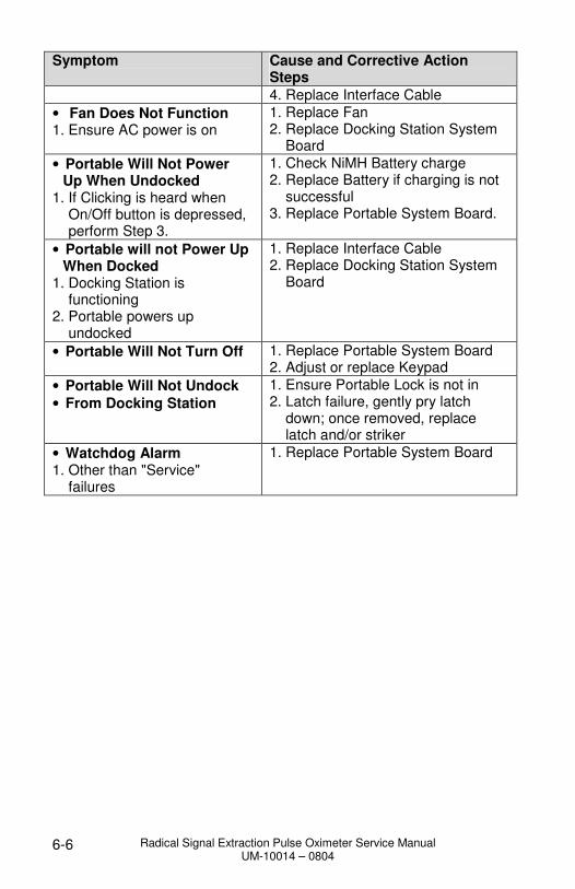
Symptom Cause and Corrective Action Steps
4. Replace Interface Cable
• Fan Does Not Function 1. Ensure AC power is on
1. Replace Fan 2. Replace Docking Station System Board
• Portable Will Not Power Up When Undocked
1. If Clicking is heard when On/Off button is depressed, perform Step 3.
1. Check NiMH Battery charge 2. Replace Battery if charging is not successful 3. Replace Portable System Board.
• Portable will not Power Up When Docked
1. Docking Station is functioning 2. Portable powers up undocked
1. Replace Interface Cable 2. Replace Docking Station System Board
• Portable Will Not Turn Off 1. Replace Portable System Board 2. Adjust or replace Keypad
• Portable Will Not Undock
• From Docking Station
1. Ensure Portable Lock is not in 2. Latch failure, gently pry latch down; once removed, replace latch and/or striker
• Watchdog Alarm 1. Other than "Service" failures
1. Replace Portable System Board

Radical Signal Extraction Pulse Oximeter Service Manual UM-10014 – 0804
6-7
6.4. Satshare Diagnostics
Note: As SatShare Diagnostics simulates physiological information (SpO2 ) and Pulse Rate values), it should be performed with caution, especially in areas with central monitoring. The attending nurse and supervisor should always be made aware that SatShare Diagnostic testing is being performed.
During transient situations, the SpO2 and pulse rate values on Radical and the multiparameter monitor may differ by more than the specified tolerance. The averaging time set on the multiparameter monitor may also affect the delay during transient situations.
6.4.1. If the SpO2 and pulse rate values displayed on a multi-parameter monitor is in question, perform the following steps.
6.4.1.1. Press Menu – General – SatShare Numbers – Yes.
6.4.2. With the Handheld docked and AC power applied, disconnect the patient cable from Radical. Press the following key sequence: Menu – About – 2 – 1 – 1 (see Service menu for number key assignments). Five (5) different SatShare values can be selected by pressing the Select key. The selected value will be displayed on the multiparameter monitor if the unit is working properly. The SatShare Diagnostics feature times out if a key is not pressed within 1 minute.
Radical Signal Extraction Pulse Oximeter Service Manual UM-10014 – 0804
7-1
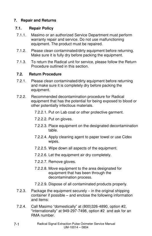
7. Repair and Returns
7.1. Repair Policy
7.1.1. Masimo or an authorized Service Department must perform warranty repair and service. Do not use malfunctioning equipment. The product must be repaired.
7.1.2. Please clean contaminated/dirty equipment before returning. Make sure it is fully dry before packing the equipment.
7.1.3. To return the Radical unit for service, please follow the Return Procedure outlined in this section.
7.2. Return Procedure
7.2.1. Please clean contaminated/dirty equipment before returning and make sure it is completely dry before packing the equipment.
7.2.2. Recommended decontamination procedure for Radical equipment that has the potential for being exposed to blood or other potentially infectious materials.
7.2.2.1. Put on Lab coat or other protective garment.
7.2.2.2. Put on gloves.
7.2.2.3. Place equipment on the designated decontamination table.
7.2.2.4. Apply cleaning agent to paper towel or use Cidex wipes.
7.2.2.5. Wipe down all aspects of the equipment.
7.2.2.6. Let the equipment air dry completely.
7.2.2.7. Remove gloves.
7.2.2.8. Move equipment to the area designated for equipment that has been through the decontamination process.
7.2.2.9. Dispose of all contaminated products properly.
7.2.3. Package the equipment securely – in the original shipping container if possible – and enclose the following information and items:
7.2.4. Call Masimo “domestically” at (800)326-4890, option #2, “internationally” at 949-297-7498, option #2 and ask for an RMA number.

Radical Signal Extraction Pulse Oximeter Service Manual UM-10014 – 0804
7-2
7.2.5. A letter or email describing in detail any symptoms or difficulties experienced with the pulse oximeter. Please include the RMA number in the letter.
7.2.6. Warranty information – a copy of the invoice or other applicable documentation must be included.
7.2.7. Purchase order number to cover repair if the oximeter is not under warranty, or for tracking purposes if the warranty is in effect.
7.2.8. Ship-to and bill-to information.
7.2.9. Person (name, telephone/Telex/fax number, email and country) to contact for any questions about the repairs.
7.2.10. A document stating the oximeter has been decontaminated for bloodborne pathogens.
7.2.11. Return pulse oximeter to the following shipping address:
Masimo Corporation
40 Parker Irvine, California
USA 92618
(Domestic Toll Free): 800-326-4890, option #2 (International): 949-297-7498, option #2 FAX: 949-297-7499
Email: [email protected]

Radical Signal Extraction Pulse Oximeter Service Manual UM-10014 – 0804
8-1
8. Analog Output/Nurse Call Test

Radical Signal Extraction Pulse Oximeter Service Manual UM-10014 – 0804
10-1
9. Docking Station Power Supply Power Measurement
Part Number 20241 and 20364
Part Number 20293
10. Docking Station System Board Power Measurement
AC
12VDCJP1
JP2 +
-
Ground point
AC
12VDC
JP1
JP2
+ -
LED Status
PIN 8
GROUND
J25
Interface
J19
PIN5
3.3VDC
PIN4
7.5VDC
PIN6
5.0VDC
SUPPLY VOLTAGE PIN2 12VDC
BATTERY VOLTAGE PIN3 4.8VDC
Optional
Battery
J21
J23PIN2
12 VDC
PIN1
12 VDC
J22
PIN1
12 VDC
Fan
DC
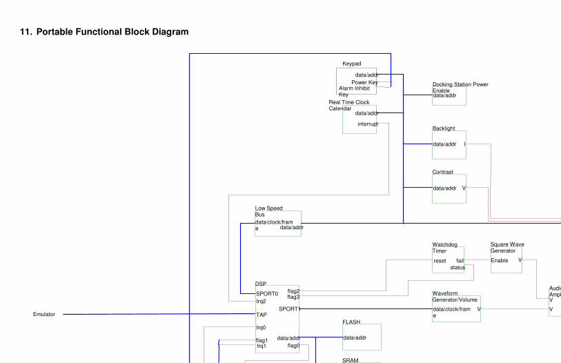
11. Portable Functional Block Diagram
Keypad
Contrast
data/addr
fail
I
data/addr
reset
Square WaveGenerator
data/addr
AudioAmplifier
WatchdogTimer
SPORT0
Power
interruptBacklight
flag2
DSP
flag1
status
Power Key
flag3
data/addr
SRAM
flag0
data/clock/frame
TAP
Alarm InhibitKey
data/addr
Emulator
Low SpeedBus
V
Real Time ClockCalendar
VIrq2
data/addr
FLASHIrq0
Irq1
V
Enable
SPORT1
data/addr
V
Docking Station PowerEnable
data/addr
data/clock/frame
WaveformGenerator/Volume
V

12. Docking Station Functional Block Diagram
Portable Battery Charger
SatShare
data/addr
data/clock/frame
SRAM
data/addr
Reset
Low Speed Bus
/Reset
/Reset
data/addr
J21 Docking Station Battery Pack Connector
data/addr
V
data/addr
12VDC
TAP
Nurse Call
7.5VDC Sepic Power Supply
LED Interface
3.3VDC
FLASH
flag1
RS-232 Level Translator
DSP
data/clock/frame
Irq0
Serial EEPROM Interface
V
5VDC
Irq1
Analog Output
data/addr
J28 Emulator Port Connector
data/addr
data/addr
I
SPORT0
Power Supervisors
V
SPORT1
CLK/Data
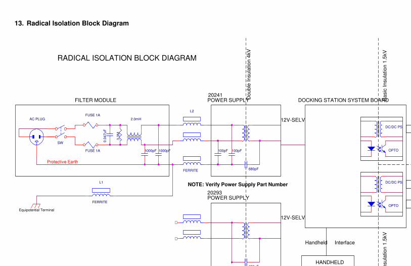
13. Radical Isolation Block Diagram
FILTER MODULE Do
ub
le I
nsu
latio
n 4
kV
L1
FERRITE
2.0mH
NOTE: Verify Power Supply Part NumberDC/DC PS
OPTO100pF
Protective Earth
1000pF
Equipotential Terminal
FUSE 1A
Ba
sic
In
su
latio
n 1
.5kV
680pF
L2
FERRITE 680pF
FUSE 1A
20293
0.0
47
uF
DC/DC PS
HANDHELD
DOCKING STATION SYSTEM BOARD
12V-SELV
OPTO
AC PLUG
RADICAL ISOLATION BLOCK DIAGRAM
Handheld Interface
POWER SUPPLY
12V-SELV
20241POWER SUPPLY
Ba
sic
In
su
latio
n 1
.5kV
3.3
M
100pF
SW
1000pF

14. Portable Wiring Interconnect
Board
Speaker
J16
J8
J3
Display
Board
NiMH Battery
Pack
J1
J9
Portable System
J1
MS-XXJ6
J17
Swivel ConnectorJ7
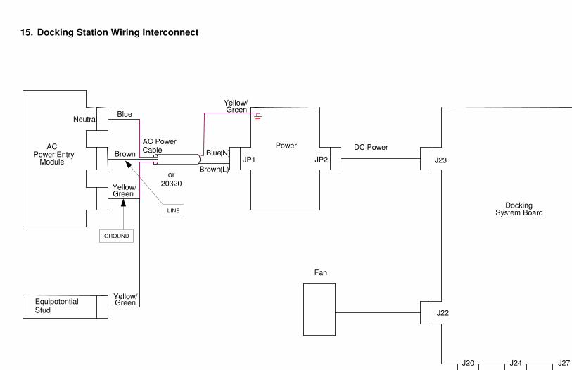
15. Docking Station Wiring Interconnect
Green
ACBlue
J24
JP2
J27
Neutral
(N)DC Power
Yellow/
EquipotentialStud
AC PowerCable
System Board
Fan
JP1
Blue
Green
J23
Docking
Yellow/
Yellow/
BrownModule
PowerPower Entry
(L)
J22
Green
Brown
J20
or20320
LINE
GROUND

16. Portable Parts List
1. Latch 10. Display Retainer 19. NiMH Battery Pack2. Top Shell 11. MS-xx Standoff Mounting Hardware (4 pcs) 20. Radical Logo Label3. Swivel Connector 12. Handheld System Board 21. Lithium Coin Cell 4. Leash Pins 13. Portable System Board Mounting Hardware (2 pcs)85 22. Foam Pad 5. Speaker Gasket 14. Standoff (4 pcs)
6. Speaker 15. MS-xx mounting Hardware (4 pcs)
7. Keypad Adhesive 16. MS-3L or MS-5 or MS-7 or MS-11
8. Keypad 17. Back Shell
9. Display. 18. Plastics Hardware (6 pcs)
1.
2.
3.
4.
5.6.
7.
8.9.
10.
11.
12.13.
14.
15.
16.
17.
20
21.
22.

17. Docking Station Parts List (RDS-1, RDS-1B and RDS-3)
Note: Only RDS-1B configured Docking Stations will contain the 20284 Optional Battery Pack.
1. Front Shell 10. AC Filter Module Fuses (2 pcs) 19. DC Power Cable 2. LED Status Label 11. AC Power Entry Module 20. Top Shell 3. Radical Logo Label 12. AC Filter Module Bracket 21. Docking Station System Board (2 types)
- RDS-1 and RDS-1B (All ports available - RDS-3 (Only ports P1 and P2 availab
4
1
2
3
5
6
7
8
9
10
11
12
13
14
15
16
17
18
19
21
22
24
25
26
27
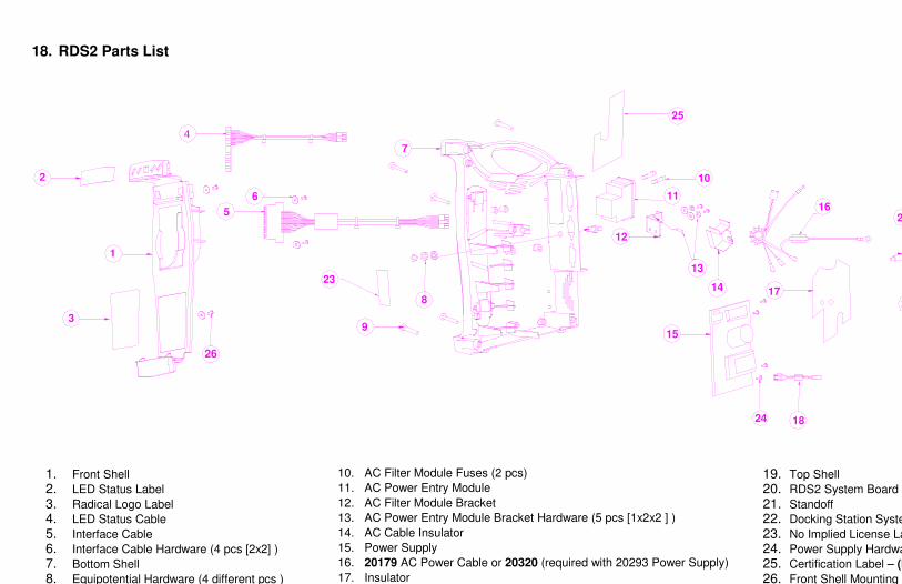
18. RDS2 Parts List
1. Front Shell 10. AC Filter Module Fuses (2 pcs) 19. Top Shell
2. LED Status Label 11. AC Power Entry Module 20. RDS2 System Board
3. Radical Logo Label 12. AC Filter Module Bracket 21. Standoff
4. LED Status Cable 13. AC Power Entry Module Bracket Hardware (5 pcs [1x2x2 ] ) 22. Docking Station System Board Mounting
5. Interface Cable 14. AC Cable Insulator 23. No Implied License Label
6. Interface Cable Hardware (4 pcs [2x2] ) 15. Power Supply 24. Power Supply Hardware (4 pcs)
7. Bottom Shell 16. 20179 AC Power Cable or 20320 (required with 20293 Power Supply) 25. Certification Label – (Port P1, P2 and P3 closed)
8. Equipotential Hardware (4 different pcs ) 17. Insulator 26. Front Shell Mounting Hardware (4 pcs [2x2] )
4
1
2
3
5
6
7
8
9
10
11
12
16
17
18
20
21
23
24
25
13
14
15
26