Radiation Protection Strategy Development for Mars Surface ...
21
45th International Conference on Environmental Systems ICES-2015-54 12-16 July 2015, Bellevue, Washington Radiation Protection Strategy Development for Mars Surface Exploration Arturo R. Ortiz 1 , Vadim Y. Rygalov 2 , and Pablo de León 3 University of North Dakota, Grand Forks, ND, 58202 Computational analyses were performed to assess space radiation shielding effectiveness of ‘minimal’ planetary surface exploration concepts developed by the University of North Dakota: the Inflatable Lunar-Martian Habitat (ILMH), Pressurized Electric Rover (PER), and NDX-2 space suit. Using the HZETRN and NUCFRG3 radiation analysis computer codes with ray-by-ray transport through three-dimensional shielding thickness distributions, the authors calculated doses in the Mars surface environment under conditions of the February 1956 solar flare and 1977 solar minimum galactic cosmic radiation. Results indicate that polyethylene shielding of 5, 10, and 15 g/cm 2 can protect the ILMH up to 11, 18, and 25 km surface elevation, respectively, while 1m of Mars regolith can protect up to 30 km. The shielded ILMH is adequate as primary radiation storm shelter, and meets permissible limits for 30 and 365 day exposures. The structural shell of the PER can protect from acute exposure only up to 5 km elevation, and hence is not adequate as a secondary storm shelter. A Mylar space suit at a thickness of 500 micrometers can protect from acute exposure only up to 4 km. The authors estimated doses for surface stays of 365 days, and found total dose varied from 176 mGy-Eq while performing minimal exploration, to 1025 mGy-Eq in a scenario that includes extravehicular activity (EVA) between 24 and 30 km elevation during a large solar flare. Acute exposure during the flare at high surface elevation approaches the threshold for acute radiation syndrome. Since the PER and space suit cannot protect from short term exposure except over a limited elevation range, fast access to a shielded habitat will always be required if a major solar storm occurs during surface roving or EVA. This drives a need to implement an early warning system for solar storms to enable safe extended surface exploration of Mars. Nomenclature AU = astronomical unit BFO = blood forming organs CNS = central nervous system EVA = extravehicular activity GCR = galactic cosmic radiation HZETRN = High Charge (Z) and Energy Transport ILMH = Inflatable Lunar-Martian Habitat mGy-Eq = milli Gray equivalent NDX = North Dakota Experimental NUCFRG = Nuclear Fragmentation OLTARIS = On Line Tool for the Assessment of Radiation in Space PEL = Permissible Exposure Limit PER = Pressurized Electric Rover SPE = solar particle event UND = University of North Dakota Z = atomic number 1 Graduate Student, Department of Space Studies, 4149 University Ave., Stop 9008, Grand Forks, ND 58202 2 Associate Professor, Department of Space Studies, 4149 University Ave., Stop 9008, Grand Forks, ND 58202 3 Associate Professor, Department of Space Studies, 4149 University Ave., Stop 9008, Grand Forks, ND 58202
Transcript of Radiation Protection Strategy Development for Mars Surface ...

45th International Conference on Environmental Systems ICES-2015-54 12-16 July 2015, Bellevue, Washington
Radiation Protection Strategy Development for Mars
Surface Exploration
Arturo R. Ortiz
1, Vadim Y. Rygalov
2, and Pablo de León
3
University of North Dakota, Grand Forks, ND, 58202
Computational analyses were performed to assess space radiation shielding effectiveness
of ‘minimal’ planetary surface exploration concepts developed by the University of North
Dakota: the Inflatable Lunar-Martian Habitat (ILMH), Pressurized Electric Rover (PER),
and NDX-2 space suit. Using the HZETRN and NUCFRG3 radiation analysis computer
codes with ray-by-ray transport through three-dimensional shielding thickness distributions,
the authors calculated doses in the Mars surface environment under conditions of the
February 1956 solar flare and 1977 solar minimum galactic cosmic radiation. Results
indicate that polyethylene shielding of 5, 10, and 15 g/cm2 can protect the ILMH up to 11, 18,
and 25 km surface elevation, respectively, while 1m of Mars regolith can protect up to 30
km. The shielded ILMH is adequate as primary radiation storm shelter, and meets
permissible limits for 30 and 365 day exposures. The structural shell of the PER can protect
from acute exposure only up to 5 km elevation, and hence is not adequate as a secondary
storm shelter. A Mylar space suit at a thickness of 500 micrometers can protect from acute
exposure only up to 4 km. The authors estimated doses for surface stays of 365 days, and
found total dose varied from 176 mGy-Eq while performing minimal exploration, to 1025
mGy-Eq in a scenario that includes extravehicular activity (EVA) between 24 and 30 km
elevation during a large solar flare. Acute exposure during the flare at high surface
elevation approaches the threshold for acute radiation syndrome. Since the PER and space
suit cannot protect from short term exposure except over a limited elevation range, fast
access to a shielded habitat will always be required if a major solar storm occurs during
surface roving or EVA. This drives a need to implement an early warning system for solar
storms to enable safe extended surface exploration of Mars.
Nomenclature
AU = astronomical unit
BFO = blood forming organs
CNS = central nervous system
EVA = extravehicular activity
GCR = galactic cosmic radiation
HZETRN = High Charge (Z) and Energy Transport
ILMH = Inflatable Lunar-Martian Habitat
mGy-Eq = milli Gray equivalent
NDX = North Dakota Experimental
NUCFRG = Nuclear Fragmentation
OLTARIS = On Line Tool for the Assessment of Radiation in Space
PEL = Permissible Exposure Limit
PER = Pressurized Electric Rover
SPE = solar particle event
UND = University of North Dakota
Z = atomic number
1 Graduate Student, Department of Space Studies, 4149 University Ave., Stop 9008, Grand Forks, ND 58202
2 Associate Professor, Department of Space Studies, 4149 University Ave., Stop 9008, Grand Forks, ND 58202
3 Associate Professor, Department of Space Studies, 4149 University Ave., Stop 9008, Grand Forks, ND 58202

International Conference on Environmental Systems
2
I. Introduction
Human exploration of Mars will involve surface stays of one Earth year or longer. During an extended stay, the
crew may experience a major solar particle event (SPE) in addition to background galactic cosmic radiation (GCR).
Since Mars does not have the protection of a planetary magnetosphere, doses of ionizing radiation will be high. The
thin Mars atmosphere will provide relatively little protection. Without radiation shielding, Permissible Exposure
Limits (PELs)1,2
will be exceeded. Astronauts will require the protection of a shielded habitat, with very limited
protection provided by surface rovers and space suits.
We performed computational analyses to assess radiation doses inside ‘minimal’ planetary surface exploration
concepts developed by the University of North Dakota (UND) under a NASA grant: the Inflatable Lunar-Martian
Habitat (ILMH), Pressurized Electric Rover (PER), and the North Dakota Experimental (NDX)-2 space suit.
Initially, these concepts were developed to provide minimal life support structures for astronauts. For the ILMH, we
examined several shielding configurations and identified surface elevations where the ILMH could be deployed to
ensure PELs are met. For the PER, we calculated internal doses under operationally realistic materials and
thicknesses. For the space suit, we calculated internal doses under operationally realistic suit fabric and thicknesses.
We estimated doses for minimal, intermediate, and extreme surface exploration scenarios.
II. Method
A. Overview
These investigations used the latest version of the HZETRN (High Charge [Z] and Energy Transport) and
NUCFRG3 (Nuclear Fragmentation 3) computer codes, developed by the NASA Langley Research Center, available
through the On Line Tool for the Assessment of Radiation in Space (OLTARIS) web site.3 HZETRN transport
algorithms solve numerically the linearized Boltzmann transport equation using Bethe-Bloch theory, along with the
straight-ahead and continuous slowing down approximations.4 The most recent version accounts for neutron
backscatter from planetary surfaces. NUCFRG3 analyzes heavy ion collisions using the abrasion-ablation model of
heavy ion fragmentation to estimate cross sections for production of isotopes. It computes production cross sections
of emerging particles for input into HZETRN.5-7
We assumed a worst case external radiation environment. The February 1956 solar flare is considered to be the
most severe SPE ever observed.8 The 1977 solar minimum galactic cosmic radiation (GCR) is considered to be a
severe environment.9 Calculations used the NASA Langley model of the February 1956 solar flare and the
Badhwar-O’Neill 2010 model of 1977 solar minimum GCR, in the Mars surface environment of the Mars-GRAM
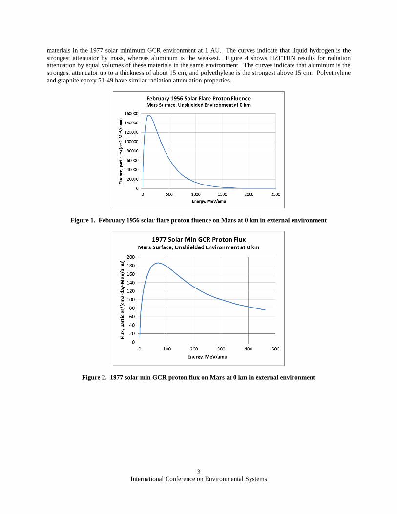
2001 atmospheric model. Figure 1 shows the proton spectrum generated by HZETRN for the February 1956 solar
flare after transport through the Mars atmosphere to 0 km surface elevation, in the external environment. Although
other ion species are present in the solar flare, proton fluence is dominant. Figure 2 shows the proton spectrum
generated by HZETRN for 1977 solar minimum GCR after transport through the Mars atmosphere to 0 km surface
elevation, in the external environment. Although other ion species are present in the GCR, the proton flux is
highest. We defined surface environments of acute, 30 day, and 365 day exposure. Acute exposure calculations
were used to identify situations where an astronaut could be near the threshold for acute radiation syndrome.
Calculations of 30 day and 365 day exposures were used to compare levels to NASA dose limits for short term or
career non-cancer effects.
We implemented very simple models of the ILMH, PER, and space suit, for evaluation of internal doses. For
each concept, the shielding was represented as a three-dimensional material thickness distribution. Each thickness
distribution consists of a 42-ray geodesic sphere centered at interior target points, with a shielding material thickness
specified along each ray. The rays are evenly distributed over a full solid angle of 4 steradians, with each ray
accompanied by an opposite ray.
B. ILMH
We represented the ILMH as a hollow box of dimensions 12.2 m x 3m x 2.4 m, with no internal shielding, seated
on the Martian surface. We examined shielding over the roof and along the four walls, with no floor shielding,
assuming the planetary body provides shielding from the floor direction.
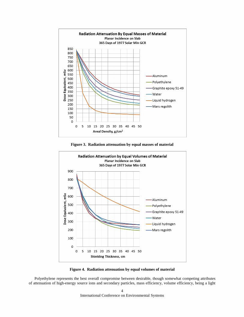
For shielding materials, we considered liquid hydrogen, water, graphite epoxy 51-49, polyethylene, and Mars
regolith. A preliminary assessment compared the shielding effectiveness of these five materials to aluminum, using
HZETRN and NUCFRG3. Figure 3 shows HZETRN results for radiation attenuation by equal masses of these six
International Conference on Environmental Systems
3
materials in the 1977 solar minimum GCR environment at 1 AU. The curves indicate that liquid hydrogen is the
strongest attenuator by mass, whereas aluminum is the weakest. Figure 4 shows HZETRN results for radiation
attenuation by equal volumes of these materials in the same environment. The curves indicate that aluminum is the
strongest attenuator up to a thickness of about 15 cm, and polyethylene is the strongest above 15 cm. Polyethylene
and graphite epoxy 51-49 have similar radiation attenuation properties.
Figure 1. February 1956 solar flare proton fluence on Mars at 0 km in external environment
Figure 2. 1977 solar min GCR proton flux on Mars at 0 km in external environment
International Conference on Environmental Systems
4
Figure 3. Radiation attenuation by equal masses of material
Figure 4. Radiation attenuation by equal volumes of material
Polyethylene represents the best overall compromise between desirable, though somewhat competing attributes
of attenuation of high-energy source ions and secondary particles, mass efficiency, volume efficiency, being a light
International Conference on Environmental Systems
5
material that reduces production of secondary particles, hydrogen-rich content, and high number of electrons per
unit mass. Hence, we selected polyethylene as the primary shielding material for the ILMH. We selected Mars
regolith as a secondary shielding material, in case massive shielding is required. This enables exploitation of a
planetary resource, if required.
We defined external surface radiation environments of acute, 30 day, and 365 day exposure, over an elevation
range of -10 to 30 km. For each of these environments, we assumed an SPE would occur during the time interval, in
addition to background GCR. Table 1 shows our definitions of the surface environments.
Table 1. Surface environments for exposure inside the ILMH
Exposure External Environment
Acute February 1956 solar flare and 1 day of 1977 solar minimum GCR
30 day February 1956 solar flare and 30 days of 1977 solar minimum GCR
365 day February 1956 solar flare and 365 days of 1977 solar minimum GCR
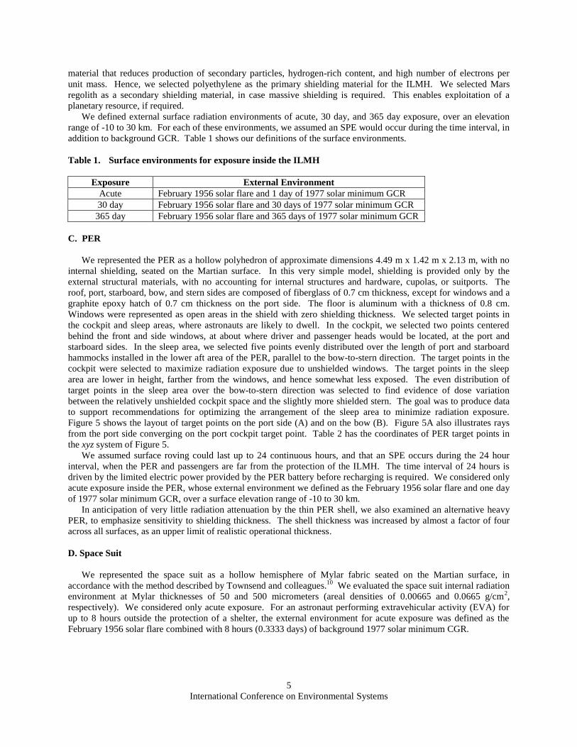
C. PER
We represented the PER as a hollow polyhedron of approximate dimensions 4.49 m x 1.42 m x 2.13 m, with no
internal shielding, seated on the Martian surface. In this very simple model, shielding is provided only by the
external structural materials, with no accounting for internal structures and hardware, cupolas, or suitports. The
roof, port, starboard, bow, and stern sides are composed of fiberglass of 0.7 cm thickness, except for windows and a
graphite epoxy hatch of 0.7 cm thickness on the port side. The floor is aluminum with a thickness of 0.8 cm.
Windows were represented as open areas in the shield with zero shielding thickness. We selected target points in
the cockpit and sleep areas, where astronauts are likely to dwell. In the cockpit, we selected two points centered
behind the front and side windows, at about where driver and passenger heads would be located, at the port and
starboard sides. In the sleep area, we selected five points evenly distributed over the length of port and starboard
hammocks installed in the lower aft area of the PER, parallel to the bow-to-stern direction. The target points in the
cockpit were selected to maximize radiation exposure due to unshielded windows. The target points in the sleep
area are lower in height, farther from the windows, and hence somewhat less exposed. The even distribution of
target points in the sleep area over the bow-to-stern direction was selected to find evidence of dose variation
between the relatively unshielded cockpit space and the slightly more shielded stern. The goal was to produce data
to support recommendations for optimizing the arrangement of the sleep area to minimize radiation exposure.
Figure 5 shows the layout of target points on the port side (A) and on the bow (B). Figure 5A also illustrates rays
from the port side converging on the port cockpit target point. Table 2 has the coordinates of PER target points in
the xyz system of Figure 5.
We assumed surface roving could last up to 24 continuous hours, and that an SPE occurs during the 24 hour
interval, when the PER and passengers are far from the protection of the ILMH. The time interval of 24 hours is
driven by the limited electric power provided by the PER battery before recharging is required. We considered only
acute exposure inside the PER, whose external environment we defined as the February 1956 solar flare and one day
of 1977 solar minimum GCR, over a surface elevation range of -10 to 30 km.
In anticipation of very little radiation attenuation by the thin PER shell, we also examined an alternative heavy
PER, to emphasize sensitivity to shielding thickness. The shell thickness was increased by almost a factor of four
across all surfaces, as an upper limit of realistic operational thickness.
D. Space Suit
We represented the space suit as a hollow hemisphere of Mylar fabric seated on the Martian surface, in
accordance with the method described by Townsend and colleagues.10
We evaluated the space suit internal radiation
environment at Mylar thicknesses of 50 and 500 micrometers (areal densities of 0.00665 and 0.0665 g/cm2,
respectively). We considered only acute exposure. For an astronaut performing extravehicular activity (EVA) for
up to 8 hours outside the protection of a shelter, the external environment for acute exposure was defined as the
February 1956 solar flare combined with 8 hours (0.3333 days) of background 1977 solar minimum CGR.

International Conference on Environmental Systems
6
Figure 5. PER target points on port side (A) and bow (B)
International Conference on Environmental Systems
7
Table 2. PER target points (coordinates refer to Figure 5)
Target Point x, inches y, inches z, inches
Port cockpit 16 10 -43
Port hammock 1 -18 17 13.3
Port hammock 2 -18 17 29.55
Port hammock 3 -18 17 45.8
Port hammock 4 -18 17 62.05
Port hammock 5 -18 17 78.3
Starboard cockpit 16 -10 -43
Starboard hammock 1 -18 -17 13.3
Starboard hammock 2 -18 -17 29.55
Starboard hammock 3 -18 -17 45.8
Starboard hammock 4 -18 -17 62.05
Starboard hammock 5 -18 -17 78.3
E. Surface Scenarios
The authors proposed three surface scenarios with a stay of one Earth year. A minimal scenario entails exposure
in a relatively benign radiation environment. An intermediate scenario entails moderate exposure, and is more likely
to resemble operational conditions on Mars. An extreme scenario entails exposure under worst conditions, possibly
leading to acute radiation syndrome. In all three scenarios, the only protection from radiation is provided by either
the ILMH shielding, PER shell, or space suit fabric.
In the minimal scenario, the ILMH is deployed at 0 km surface elevation, under polyethylene shielding of 5
g/cm2 areal density, in the external environment of the February 1956 solar flare and 1977 solar minimum GCR.
PER roving occurs under the external radiation environment of background 1977 solar minimum GCR. For PER
dwells, we evaluated dose at the relatively exposed port cockpit target point, for conservatism. During EVA, the
astronaut is protected only by a space suit made of Mylar fabric of 500 micrometers thickness, while exposed to
background 1977 solar minimum GCR. Local EVAs of 3 hours duration occur at 0 km elevation. Short and long
excursions of PER roving occur over a surface elevation range of -4 to 4 km. Short excursions last 24 hours, of
which 8 are inside the PER and 16 are EVA. Long excursions last 72 hours, of which 24 are inside the PER and 48
are EVA. Each month, the astronaut performs 25 local EVAs, two short roving excursions, and one long roving
excursion, with excursion dwell times evenly distributed over the surface elevation range of -4 to 4 km. The
environment for acute exposure is the February 1956 solar flare occurring while inside the ILMH under one day of
background 1977 solar minimum GCR. Table 3 is a summary of surface activities and environments under the
minimal scenario.
Table 3. Minimal surface scenario
Surface Activity Radiation
Shielding
Total Duration
(Days)
External Radiation Environment
Local EVA 500 micrometers
of Mylar fabric
37.5 1977 solar min GCR at 0 km
Excursion EVAs 500 micrometers
of Mylar fabric
40 Average 1977 solar min GCR over -4 to 4 km
Excursion PER dwells PER structure 20 Average 1977 solar min GCR over -4 to 4 km
ILMH dwell 5 g/cm2
polyethylene
267.5 February 1956 solar flare and 1977 solar min
GCR at 0 km
General conditions for the intermediate and minimal scenarios are similar. The exception is that in the
intermediate scenario, the solar flare occurs during EVA at 4 km elevation, instead of while inside the ILMH.
Hence, the environment for acute exposure is the February 1956 solar flare while under the protection of the space
suit alone at 4 km elevation, under one day of background 1977 solar minimum GCR.

International Conference on Environmental Systems
8
Table 4. Climbing expedition
The extreme scenario includes a 10 day climbing expedition to 30 km elevation. For 11 of the 12 months,
general conditions for the extreme scenario are the same as for the minimal scenario, but with no solar flare while
inside the ILMH. During the remaining month, the astronaut performs only 10 local EVAs, and does not perform
any short or long excursion roving. Instead, the astronaut performs the 10 day climbing expedition up to 30 km
elevation under one day of background GCR, with a solar flare occurring during EVA between 24 and 30 km. The
environment for acute exposure is the February 1956 solar flare and one day of background 1977 solar minimum
GCR, with both the flare and the GCR averaged over 24 to 30 km elevation. Table 4 shows the activities and
environments of the climbing expedition.
III. Results
A. ILMH
We calculated internal doses at the center of the ILMH box, under polyethylene layers of 5, 10, and 15 g/cm2
areal density, and under regolith layers of 1 and 2m thickness. Figures 6 through 8 are surface plots for exposure
under polyethylene shielding for 1, 30, and 365 days, respectively. Each surface plot shows dose in the external
environment and at shielding of 5, 10, and 15 g/cm2 areal density. The plots indicate a relatively steep attenuation
slope over the first 5 g/cm2 of polyethylene, with a progressive leveling off up to 15 g/cm
2. This illustrates the
diminishing effectiveness of greater shielding thickness, and suggests that addition of another 5 g/cm2 on top of the
15 g/cm2 would result in only marginal reduction in dose.
Figures 9 through 11 are the corresponding contour plots. To assess the effectiveness of ILMH shielding, we
compared calculated doses to 150 mGy-Eq for acute exposure (1 day), and to NASA dose limits for short term or
career non-cancer effects1 (30 and 365 day). Calculated doses were interpolated to find minimum surface elevations
where limits are exceeded. Figure 9 indicates the 1 day dose exceeds 150 mGy-Eq at elevation above 5.2 km in the
external environment, above 11.5 km behind 5 g/cm2 of polyethylene, above 18.0 km behind 10 g/cm
2, and above
25.4 km behind 15 g/cm2. Figure 10 indicates that the lowest PEL for 30 day exposure, which is 250 mGy-Eq for
blood forming organs (BFO) and heart, is exceeded above 12.6 km elevation in the external environment. Figure 10
also indicates this limit is exceeded above 26.4 km behind 5 g/cm2 of polyethylene. Finally, Figure 10 indicates that
all PELs for 30 day exposure are met behind 10 g/cm2 of polyethylene shielding over the entire surface elevation
range of -10 to 30 km. Figure 11 indicates that the lowest PEL for 1 year exposure, which is 500 mGy-Eq for BFO
and heart, is exceeded above 17.6 km in the external environment. Figure 11 also indicates that all PELs for 1 year
exposure are met behind 5 g/cm2 of polyethylene shielding over the entire surface elevation range of -10 to 30 km.
For incident ions of atomic number Z ≥ 10, there is a 1 year limit of 100 mGy for the central nervous system (CNS).
However, ions of Z ≥ 10 are more likely to be found in GCR. HZETRN results indicate GCR exposure remains
below 100 mGy even in the external environment for 1 year at 30 km elevation. Therefore, we consider this limit as
being met.
Surface Activity Radiation
Shielding
Total
Duration
(Days)
External Radiation Environment
Excursion PER dwells
from 0 to 6 km
elevation
PER structure 3 Average 1977 solar min GCR from 0 to 6 km
Excursion PER dwells
from 6 to 12 km
elevation
PER structure 2 Average 1977 solar min GCR from 6 to 12 km
Excursion EVAs from
12 to 18 km elevation
500 micrometers of
Mylar fabric
2 Average 1977 solar min GCR from 12 to 18 km
Excursion EVAs from
18 to 24 km elevation
500 micrometers of
Mylar fabric
2 Average 1977 solar min GCR from 18 to 24 km
Excursion EVAs from
24 to 30 km elevation
500 micrometers of
Mylar fabric
1 February 1956 solar flare and 1977 solar min GCR,
both averaged over 24 to 30 km elevation

International Conference on Environmental Systems
9
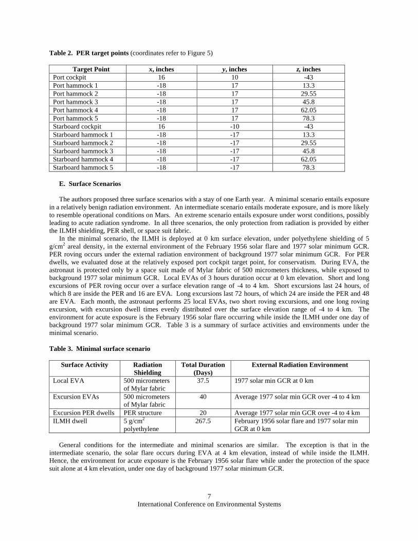
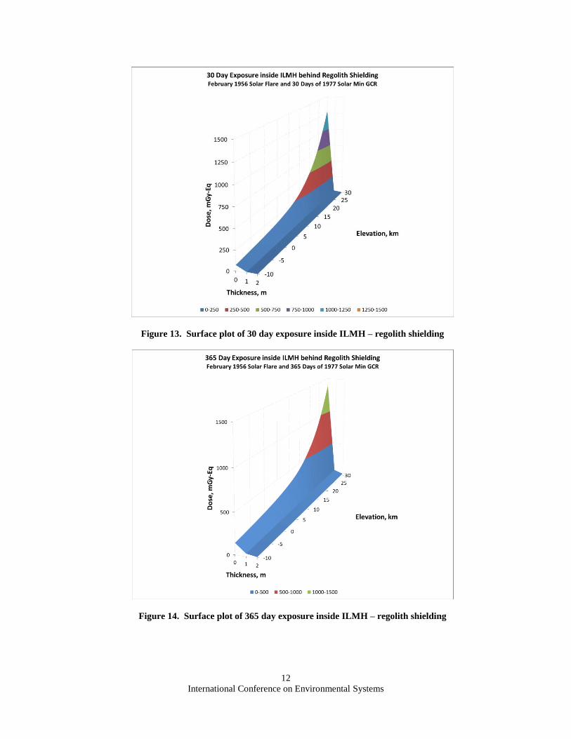
Figures 12 through 14 are surface plots for exposure under regolith shielding for 1, 30, and 365 days,
respectively. Each surface plot shows dose in the external environment and under 1 and 2m of regolith thickness.
(The external environment is the same as for polyethylene shielding.) The plots indicate a very steep attenuation
slope over the first meter of regolith, with a much lower slope over the second meter. This illustrates the
diminishing effectiveness of greater shielding thickness, as similarly illustrated by the surface plots for polyethylene
shielding. The plots suggest that addition of a third meter of regolith would result in only marginal reduction in
dose. Figures 15 through 17 are the corresponding contour plots. They indicate that 1m of regolith shielding is
sufficient to meet a 150 mGy-Eq limit for acute exposure, and PELs for 30 day and 1 year exposure, over the entire
surface elevation range of -10 to 30 km.
Figure 6. Surface plot of 1 day exposure inside ILMH – polyethylene shielding
Figure 7. Surface plot of 30 day exposure inside ILMH – polyethylene shielding

International Conference on Environmental Systems
10
Figure 8. Surface plot of 365 day exposure inside ILMH – polyethylene shielding
Figure 9. Contour plot of 1 day exposure inside ILMH – polyethylene shielding.
Figure 10. Contour plot of 30 day exposure inside ILMH – polyethylene shielding

International Conference on Environmental Systems
11
Figure 11. Contour plot of 365 day exposure inside ILMH – polyethylene shielding
Figure 12. Surface plot of 1 day exposure inside ILMH – regolith shielding
International Conference on Environmental Systems
12
Figure 13. Surface plot of 30 day exposure inside ILMH – regolith shielding
Figure 14. Surface plot of 365 day exposure inside ILMH – regolith shielding
International Conference on Environmental Systems
13
Figure 15. Contour plot of 1 day exposure inside ILMH – regolith shielding
Figure 16. Contour plot of 30 day exposure inside ILMH – regolith shielding
Figure 17. Contour plot of 365 day exposure inside ILMH – regolith shielding
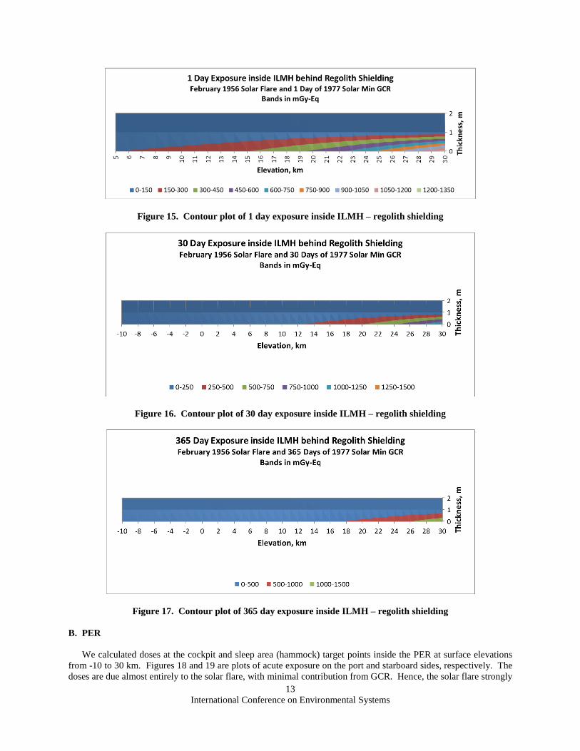
B. PER
We calculated doses at the cockpit and sleep area (hammock) target points inside the PER at surface elevations
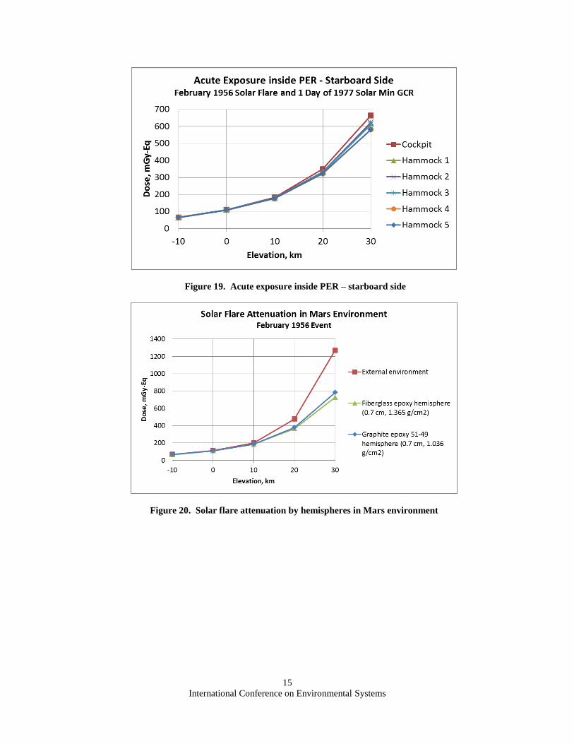
from -10 to 30 km. Figures 18 and 19 are plots of acute exposure on the port and starboard sides, respectively. The
doses are due almost entirely to the solar flare, with minimal contribution from GCR. Hence, the solar flare strongly

International Conference on Environmental Systems
14
dominates the internal radiation environment. At 30 km, the dose at the port cockpit point in the external
environment is 1269 mGy-Eq, which exceeds the 700 mGy threshold for acute radiation syndrome. Figure 18
indicates that the very light shielding of the thin PER shell reduces it to 665 mGy-Eq, which is about half of the
external environment level. Figures 18 and 19 indicate dose is highest at the target points behind the cockpit
windows, with a general, though small downward trend in dose at hammock target points in the bow-to-stern
direction. This is not surprising, as the cockpit target points have minimal shielding behind large windows, while
the hammock target points are behind the very light shielding of the PER shell, and at lower height than the cockpit
windows. However, the downward trend in dose in the bow-to-stern direction is small, and it does not indicate
existence of cold areas in the internal radiation field. Results do not support optimum repositioning of crew sleep
areas. Interpolation of port cockpit doses indicates exposure exceeds 150 mGy-Eq above 5.5 km.
A cursory examination of Figures 18 and 19 indicates similar trends in dose on the port and starboard sides.
However, there are slightly different trends on the port and starboard sides, due to the shielding asymmetry caused
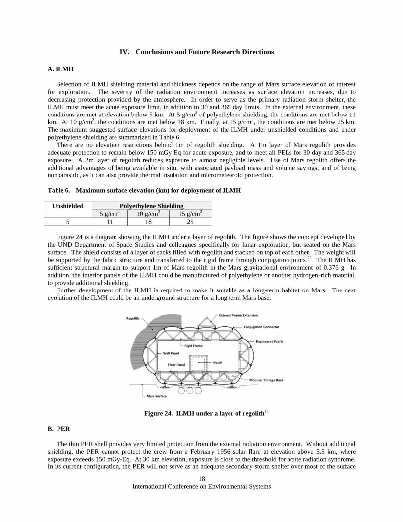
by the graphite epoxy hatch on the port side. Figure 20 shows HZETRN results for attenuation of SPE by
hemispheres of fiberglass epoxy and graphite epoxy of 0.7 cm thickness, in the Mars surface environment. The
plots indicate that fiberglass epoxy is a slightly better attenuator of SPE than graphite epoxy over the entire surface
elevation range. Port target points have diminishing shielding behind graphite epoxy and increasing shielding
behind fiberglass epoxy in the bow-to-stern direction, which impacts slightly the dose trend from SPE in the bow-to-
stern direction. Since the starboard side is all fiberglass epoxy, there is a slight asymmetry in SPE dose trends
between the port and starboard sides. Figure 21 shows HZETRN results for attenuation of GCR by hemispheres of
fiberglass epoxy and graphite epoxy of 0.7 cm thickness, in the Mars surface environment. The plots indicate that
graphite epoxy is a slightly better attenuator of GCR than fiberglass epoxy over the entire surface elevation range.
Again, the asymmetry caused by the graphite epoxy hatch on the port side causes a small difference in trends of
GCR dose between the port and starboard sides. Since the SPE environment is very dominant in acute exposure,
trending for the total dose from SPE and GCR environments essentially follows the SPE trend.
Figure 18. Acute exposure inside PER – port side
International Conference on Environmental Systems
15
Figure 19. Acute exposure inside PER – starboard side
Figure 20. Solar flare attenuation by hemispheres in Mars environment

International Conference on Environmental Systems
16
Figure 21. GCR attenuation by hemispheres in Mars environment
Figure 22 is a plot comparing acute exposure inside the baseline and heavy PERs on the port side over a surface
elevation range of -10 to 30 km. It indicates higher attenuation inside the heavy PER, as expected, with similar
trends in the bow-to-stern direction. For both the baseline and heavy PERs, the highest dose occurs at the cockpit
target point. In the baseline PER, the port cockpit dose at 30 km is 665 mGy-Eq, while in the heavy PER it is 327
mGy-Eq, about half the level of the baseline PER. Hence, an almost fourfold increase in shielding reduced the dose
only by about one half, indicating the diminishing effectiveness of increased shielding thickness.
Figure 22. Acute exposure inside baseline and heavy PERs – port side

International Conference on Environmental Systems
17
Figure 23. Acute exposure during surface EVA
C. Space Suit
We computed dose at the center of the Mylar hemisphere for acute exposure over a surface elevation range of
-10 to 30 km. Figure 23 shows acute exposure during surface EVA, where the astronaut is protected only by the
space suit fabric. The plots show doses in the external environment and under the protection of 50 and 500
micrometers of Mylar fabric. At only 8 hours of background GCR, the dose due to solar flare is strongly dominant,
while the contribution from GCR is minimal. Results indicate there is minimal attenuation of radiation from the
external environment level, even inside 500 micrometers of Mylar. Under 500 micrometers of Mylar, exposure
exceeds 150 mGy-Eq at elevation above 4.3 km. The 700 mGy threshold for acute radiation syndrome is exceeded
at elevation above 23.1 km.
D. Surface Scenarios
Total radiation exposure varied considerably over the three surface scenarios. Total exposures and acute
exposures from the solar flare and background GCR during EVA are summarized in Table 5. Limits for 1 year
exposure are met under the minimal and intermediate scenarios. Under the intermediate scenario, most of the 221
mGy-Eq total exposure is due to the solar flare that occurs at 4 km elevation while the astronaut is performing EVA
under the protection of 500 micrometers of Mylar fabric. The total exposure to solar flare and GCR during this
EVA is 139 mGy-Eq, which is below the 150 mGy-Eq limit. Under the extreme scenario, the 500 mGy-Eq limit for
BFO and heart is exceeded. Most of the 1025 mGy-Eq total exposure is due to the 1 day mountain climb from 24 to
30 km elevation, where the solar flare occurs while the astronaut is performing EVA under the protection of 500
micrometers of Mylar fabric. Exposure during this EVA is 628 mGy-Eq, which is close to the threshold of 700
mGy for acute radiation syndrome. (Under all three scenarios, the 100 mGy limit for CNS at Z ≥ 10 is met, since 1
year GCR exposure is below 100 mGy even at 30 km elevation.)
Table 5. Exposure for 365 day surface stay
Surface Scenario Acute Exposure from Solar Flare and
Background GCR during EVA
(mGy-Eq)
Total Exposure (mGy-Eq)
Minimal - 176
Intermediate 139 221
Extreme 628 1025
International Conference on Environmental Systems
18
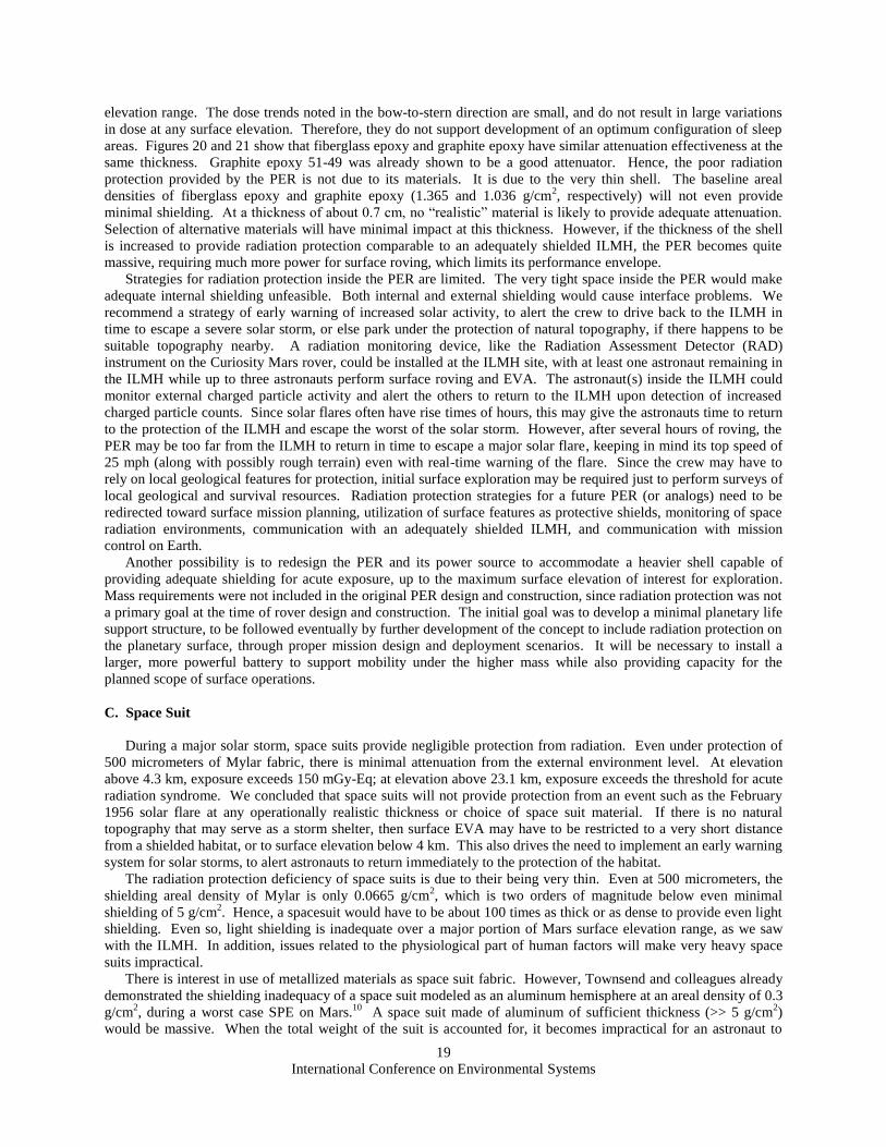
IV. Conclusions and Future Research Directions
A. ILMH
Selection of ILMH shielding material and thickness depends on the range of Mars surface elevation of interest
for exploration. The severity of the radiation environment increases as surface elevation increases, due to
decreasing protection provided by the atmosphere. In order to serve as the primary radiation storm shelter, the
ILMH must meet the acute exposure limit, in addition to 30 and 365 day limits. In the external environment, these
conditions are met at elevation below 5 km. At 5 g/cm2 of polyethylene shielding, the conditions are met below 11
km. At 10 g/cm2, the conditions are met below 18 km. Finally, at 15 g/cm
2, the conditions are met below 25 km.
The maximum suggested surface elevations for deployment of the ILMH under unshielded conditions and under
polyethylene shielding are summarized in Table 6.
There are no elevation restrictions behind 1m of regolith shielding. A 1m layer of Mars regolith provides
adequate protection to remain below 150 mGy-Eq for acute exposure, and to meet all PELs for 30 day and 365 day
exposure. A 2m layer of regolith reduces exposure to almost negligible levels. Use of Mars regolith offers the
additional advantages of being available in situ, with associated payload mass and volume savings, and of being
nonparasitic, as it can also provide thermal insulation and micrometeoroid protection.
Table 6. Maximum surface elevation (km) for deployment of ILMH
Unshielded Polyethylene Shielding
5 g/cm2
10 g/cm2 15 g/cm
2 5 11 18 25
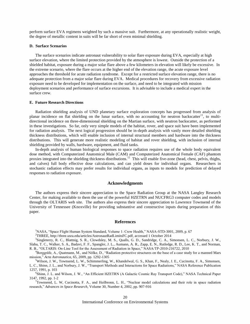
Figure 24 is a diagram showing the ILMH under a layer of regolith. The figure shows the concept developed by
the UND Department of Space Studies and colleagues specifically for lunar exploration, but seated on the Mars
surface. The shield consists of a layer of sacks filled with regolith and stacked on top of each other. The weight will
be supported by the fabric structure and transferred to the rigid frame through conjugation joints.11
The ILMH has
sufficient structural margin to support 1m of Mars regolith in the Mars gravitational environment of 0.376 g. In
addition, the interior panels of the ILMH could be manufactured of polyethylene or another hydrogen-rich material,
to provide additional shielding.
Further development of the ILMH is required to make it suitable as a long-term habitat on Mars. The next
evolution of the ILMH could be an underground structure for a long term Mars base.
Figure 24. ILMH under a layer of regolith11
B. PER
The thin PER shell provides very limited protection from the external radiation environment. Without additional
shielding, the PER cannot protect the crew from a February 1956 solar flare at elevation above 5.5 km, where
exposure exceeds 150 mGy-Eq. At 30 km elevation, exposure is close to the threshold for acute radiation syndrome.
In its current configuration, the PER will not serve as an adequate secondary storm shelter over most of the surface
International Conference on Environmental Systems
19
elevation range. The dose trends noted in the bow-to-stern direction are small, and do not result in large variations
in dose at any surface elevation. Therefore, they do not support development of an optimum configuration of sleep
areas. Figures 20 and 21 show that fiberglass epoxy and graphite epoxy have similar attenuation effectiveness at the
same thickness. Graphite epoxy 51-49 was already shown to be a good attenuator. Hence, the poor radiation
protection provided by the PER is not due to its materials. It is due to the very thin shell. The baseline areal
densities of fiberglass epoxy and graphite epoxy (1.365 and 1.036 g/cm2, respectively) will not even provide
minimal shielding. At a thickness of about 0.7 cm, no “realistic” material is likely to provide adequate attenuation.
Selection of alternative materials will have minimal impact at this thickness. However, if the thickness of the shell
is increased to provide radiation protection comparable to an adequately shielded ILMH, the PER becomes quite
massive, requiring much more power for surface roving, which limits its performance envelope.
Strategies for radiation protection inside the PER are limited. The very tight space inside the PER would make
adequate internal shielding unfeasible. Both internal and external shielding would cause interface problems. We
recommend a strategy of early warning of increased solar activity, to alert the crew to drive back to the ILMH in
time to escape a severe solar storm, or else park under the protection of natural topography, if there happens to be
suitable topography nearby. A radiation monitoring device, like the Radiation Assessment Detector (RAD)
instrument on the Curiosity Mars rover, could be installed at the ILMH site, with at least one astronaut remaining in
the ILMH while up to three astronauts perform surface roving and EVA. The astronaut(s) inside the ILMH could
monitor external charged particle activity and alert the others to return to the ILMH upon detection of increased
charged particle counts. Since solar flares often have rise times of hours, this may give the astronauts time to return
to the protection of the ILMH and escape the worst of the solar storm. However, after several hours of roving, the
PER may be too far from the ILMH to return in time to escape a major solar flare, keeping in mind its top speed of
25 mph (along with possibly rough terrain) even with real-time warning of the flare. Since the crew may have to
rely on local geological features for protection, initial surface exploration may be required just to perform surveys of
local geological and survival resources. Radiation protection strategies for a future PER (or analogs) need to be
redirected toward surface mission planning, utilization of surface features as protective shields, monitoring of space
radiation environments, communication with an adequately shielded ILMH, and communication with mission
control on Earth.
Another possibility is to redesign the PER and its power source to accommodate a heavier shell capable of
providing adequate shielding for acute exposure, up to the maximum surface elevation of interest for exploration.
Mass requirements were not included in the original PER design and construction, since radiation protection was not
a primary goal at the time of rover design and construction. The initial goal was to develop a minimal planetary life
support structure, to be followed eventually by further development of the concept to include radiation protection on
the planetary surface, through proper mission design and deployment scenarios. It will be necessary to install a
larger, more powerful battery to support mobility under the higher mass while also providing capacity for the
planned scope of surface operations.
C. Space Suit
During a major solar storm, space suits provide negligible protection from radiation. Even under protection of
500 micrometers of Mylar fabric, there is minimal attenuation from the external environment level. At elevation
above 4.3 km, exposure exceeds 150 mGy-Eq; at elevation above 23.1 km, exposure exceeds the threshold for acute
radiation syndrome. We concluded that space suits will not provide protection from an event such as the February
1956 solar flare at any operationally realistic thickness or choice of space suit material. If there is no natural
topography that may serve as a storm shelter, then surface EVA may have to be restricted to a very short distance
from a shielded habitat, or to surface elevation below 4 km. This also drives the need to implement an early warning
system for solar storms, to alert astronauts to return immediately to the protection of the habitat.
The radiation protection deficiency of space suits is due to their being very thin. Even at 500 micrometers, the
shielding areal density of Mylar is only 0.0665 g/cm2, which is two orders of magnitude below even minimal
shielding of 5 g/cm2. Hence, a spacesuit would have to be about 100 times as thick or as dense to provide even light
shielding. Even so, light shielding is inadequate over a major portion of Mars surface elevation range, as we saw
with the ILMH. In addition, issues related to the physiological part of human factors will make very heavy space
suits impractical.
There is interest in use of metallized materials as space suit fabric. However, Townsend and colleagues already
demonstrated the shielding inadequacy of a space suit modeled as an aluminum hemisphere at an areal density of 0.3
g/cm2, during a worst case SPE on Mars.
10 A space suit made of aluminum of sufficient thickness (>> 5 g/cm
2)
would be massive. When the total weight of the suit is accounted for, it becomes impractical for an astronaut to
International Conference on Environmental Systems
20
perform surface EVA regimens weighted by such a massive suit. Furthermore, at any operationally realistic weight,
the degree of metallic content in suits will be far short of even minimal shielding.
D. Surface Scenarios
The surface scenarios indicate astronaut vulnerability to solar flare exposure during EVA, especially at high
surface elevation, where the limited protection provided by the atmosphere is lowest. Outside the protection of a
shielded habitat, exposure during a major solar flare above a few kilometers in elevation will likely be excessive. In
the extreme scenario, where the flare occurs at the higher end of the elevation range, the acute exposure level
approaches the threshold for acute radiation syndrome. Except for a restricted surface elevation range, there is no
adequate protection from a major solar flare during EVA. Medical procedures for recovery from excessive radiation
exposure need to be developed for implementation on the surface, and need to be integrated with mission
deployment scenarios and performance of surface excursions. It is advisable to include a medical expert in the
surface crew.
E. Future Research Directions
Radiation shielding analysis of UND planetary surface exploration concepts has progressed from analysis of
planar incidence on flat shielding on the lunar surface, with no accounting for neutron backscatter11
, to multi-
directional incidence on three-dimensional shielding on the Martian surface, with neutron backscatter, as performed
in these investigations. So far, only very simple models of the habitat, rover, and space suit have been implemented
for radiation analysis. The next logical progression should be in-depth analysis with vastly more detailed shielding
thickness distributions, which will enable inclusion of internal structural members and hardware into the thickness
distributions. This will generate more realistic modeling of habitat and rover shielding, with inclusion of internal
shielding provided by walls, hardware, equipment, and fluid tanks.
In-depth analysis of human biological responses to space radiation requires use of the whole body equivalent
dose method, with Computerized Anatomical Male (CAM) and Computerized Anatomical Female (CAF) phantom
proxies integrated into the shielding thickness distributions.12
This will enable five-zone (head, chest, pelvis, thighs,
and calves) full body effective dose calculations, and can yield doses for individual organs. Researchers in
stochastic radiation effects may prefer results for individual organs, as inputs to models for prediction of delayed
responses to radiation exposure.
Acknowledgments
The authors express their sincere appreciation to the Space Radiation Group at the NASA Langley Research
Center, for making available to them the use of the powerful HZETRN and NUCFRG3 computer codes and models
through the OLTARIS web site. The authors also express their sincere appreciation to Lawrence Townsend of the
University of Tennessee (Knoxville) for providing substantive and constructive inputs during preparation of this
paper.
References
1NASA, “Space Flight Human System Standard, Volume 1: Crew Health,” NASA-STD-3001, 2009, p. 67 2THREE, http://three.usra.edu/articles/AstronautRadLimitsFC.pdf, accessed 1 October 2014 3Singleterry, R. C., Blattnig, S. R., Clowdsley, M. S., Qualls, G. D., Sandridge, C. A., Simonsen, L. C., Norbury, J. W.,
Slaba, T. C., Walker, S. A., Badavi, F. F., Spangler, J. L., Aumann, A. R., Zapp, E. N., Rutledge, R. D., Lee, K. T., and Norman,
R. B., “OLTARIS: On-Line Tool for the Assessment of Radiation in Space,” NASA/TP-2010-216722, 2010 4Borggräfe, A., Quatmann, M., and Nölke, D., “Radiation protective structures on the base of a case study for a manned Mars
mission,” Acta Astronautica, 65, 2009, pp. 1292-1305 5Wilson, J. W., Townsend, L. W., Schimmerling, W., Khandelwal, G. S., Khan, F., Nealy, J. E., Cucinotta, F. A., Simonsen,
L. C., Shinn, J. L., and Norbury, J. W., “Transport Methods and Interactions for Space Radiations,” NASA Reference Publication
1257, 1991, p. 103 6Shinn, J. L. and Wilson, J. W., “An Efficient HZETRN (A Galactic Cosmic Ray Transport Code),” NASA Technical Paper
3147, 1992, pp. 1-2 7Townsend, L. W, Cucinotta, F. A., and Heilbronn, L. H., “Nuclear model calculations and their role in space radiation
research,” Advances in Space Research, Volume 30, Number 4, 2002, pp. 907-916
International Conference on Environmental Systems
21
8Vashenyuk, E. V., Balabin, Y. V., and Miroshnichenko, L. I., “Relativistic solar protons in the ground level event of 23
February 1956: New study,” Advances in Space Research, 41, 2008, pp. 926–935 9Badavi, F. F., Wilson, J. W, and Hunter, A., “Numerical study of the generation of linear energy transfer spectra for space
radiation applications,” Advances in Space Research, 47, 2011, pp. 1608-1615 10Townsend, L. W., Anderson, J. A., Adamczyk, A. M., and Werneth, C. M., “Estimates of Carrington-class solar particle
event radiation exposures as a function of altitude in the atmosphere of Mars,” Acta Astronautica, 89, 2013, pp. 189-194 11Schneider, I., Daga, A., de León, P., and Harris, G. (2010), “Interim Report for the Human Exploration of the Moon and
Mars: Space radiation protection and mitigation strategies for a long term duration lunar base (a NASA funded study),” 40th
International Conference on Environmental Systems, CP6220, AIAA, Washington, DC, 2010, DOI/ISBN 10.2514/6.2010-6220 12Singleterry, R. C., Blattnig, S. R., Clowdsley, M. S., Qualls, G. D., Sandridge, C. A., Simonsen, L. C., Slaba, T. C., Walker,
S. A., Badavi, F. F., Spangler, J. L., Aumann, A. R., Zapp, E. N., Rutledge, R. D., Lee, K. T., Norman, R. B., and Norbury, J. W.,
“OLTARIS: On-line tool for the assessment of radiation in space,” Acta Astronautica, 68, 2011, pp. 1086-1097