RADIATION EFFECTS IN SPACE ELECTRONICS
66
ESA UNCLASSIFIED - Releasable to the Public Christian Poivey 16/05/2019 RADIATION EFFECTS IN SPACE ELECTRONICS 6 th EIROforum School on Instrumentation
Transcript of RADIATION EFFECTS IN SPACE ELECTRONICS

ESA UNCLASSIFIED - Releasable to the Public
Christian Poivey
16/05/2019
RADIATION EFFECTS IN SPACE ELECTRONICS
6th EIROforum School on Instrumentation

ESA UNCLASSIFIED - Releasable to the Public Christian Poivey | 16/05/2019 | Slide 2
Why Are We Concerned by Radiation in Space ?
• There is an abundance of high-energy particles in space
• Space radiation can be dangerous for humans in space.
• Space radiation environment may also be dangerous for materials and electronic components used in spacecraft
SOHO, the effect of solar Coronal Mass Ejection resulting in a strong high energy proton event. Proton impinging on the imaging sensor of the instrument are observed as bright pixels or streaks.
High-energy particle impact on Schottky diode.
(J. George NSREC Radiation Effects Data Workshop 2013)

ESA UNCLASSIFIED - Releasable to the Public Christian Poivey | 16/05/2019 | Slide 3
OUTLINE
• Space radiation environment
• Radiation effects in space electronics
• Total Ionizing Dose
• Total Non Ionizing Dose (Displacement Damage)
• Single Event Effects
• Conclusion

ESA UNCLASSIFIED - Releasable to the Public Christian Poivey | 16/05/2019 | Slide 4
Sources of radiation environment in Space

ESA UNCLASSIFIED - Releasable to the Public Christian Poivey | 16/05/2019 | Slide 5
• Also known as Van-Allen
belts
• They were discovered during
the first space missions
• Electrons and protons
trapped in Earth magnetic
field (Lorentz force)
1- Trapped Radiation Belts
NASA, Radiation Belts Storm probe mission

ESA UNCLASSIFIED - Releasable to the Public Christian Poivey | 16/05/2019 | Slide 6
Trapped Radiation Belts, main characteristics
• Inner belt is dominated by a population of energetic
protons up to ~400 MeV energy range
• Inner edge is encountered as the South Atlantic
Anomaly (SAA)
• Dominates the Space Station and LEO spacecraft
environments
• Outer Belt is dominated by a population of energetic
electrons up to 7 MeV energy range
• Frequent injections and dropouts associated with
storms and solar material interacting with
magnetosphere
• Dominates the geostationary orbit environment
(mostly telecom) and Navigation (Galileo, GPS)
orbits, as well as certain Science missions in highly
elliptic orbits (XMM-Newton, INTEGRAL)
(Richard Bertram Horne Nature Physics 3, 2007)

ESA UNCLASSIFIED - Releasable to the Public Christian Poivey | 16/05/2019 | Slide 7
The South Atlantic Anomaly
(Wikimedia Commons, the free media repository)EPT flown on PROBA-V, 95 to 126 MeV proton channel
The South Atlantic Anomaly is observed as the magnetic axis is not aligned with the Earths rotational axis. The inner radiation belt thus is closer to earth above the South Atlantic as can be seen in the above images.

ESA UNCLASSIFIED - Releasable to the Public Christian Poivey | 16/05/2019 | Slide 8
2 - Solar Event Particles
• SolarEvents (Solar Flares or Coronal Mass Ejection) represent emission of a broad spectrum of particles and very high energy release.
• The electrons, protons and heavier ions ejected reach Earth in a couple of days. Radiation fluxes can be high for several days during solar flares
• The energy spectra of ejected particles are highly variable
• Solar flare frequency depends on the Solar activity cycle approximately 11 years long
• Fluences high enough to cause damage => importance of proper shielding
• Essentially unpredictable, however efforts dedicated to address the problem in various Space Weather initiatives
• Solar particles are shielded by the Earth magnetic field, however, can reach lower orbits at the polar caps.
Large solar eruption captured by SOHO on the 27 July 1999. The eruption is larger that Earth.

ESA UNCLASSIFIED - Releasable to the Public Christian Poivey | 16/05/2019 | Slide 9
Single Event Effect rates increase significantly during a Solar event
Solar Particle Events – Examples
SPEs of December 2006 (GOES)
1E-02
1E-01
1E+00
1E+01
1E+02
1E+03
11/12 12:00 12/12 00:00 12/12 12:00 13/12 00:00 13/12 12:00 14/12 00:00 14/12 12:00 15/12 00:00 15/12 12:00 16/12 00:00
Flu
x (
1/c
m2
/sr/
s)
>10 MeV
>50 MeV
>100 MeV
STS-116 spacewalk 1
STS-116 spacewalk 2
SEUs on SEASTAR SSR (Poivey 2003)

ESA UNCLASSIFIED - Releasable to the Public Christian Poivey | 16/05/2019 | Slide 10
• Discovered in 1912 by Austrian Victor Hess
• GCRs originate from outside our solar system, most probably from the Milky
Way and are thought to be generated in supernovae (as suggested by Enrico
Fermi in 1949).
• GCR are charged particles accelerated to near speed of light (can reach ~
1020 eV range (LHC ~ 1012 eV)
• Flux ~ 4 particles/cm2/s in space, anti-correlation with solar activity
• Geomagnetic field offers some shielding
• Atmosphere shields Earth’s surface from “primary” cosmic rays
• Collision in upper atmosphere produce “secondary” cosmic rays – some reach
ground level (average person is crossed by ~ 100 relativistic muons per
second)
3 – Galactic Cosmic Rays (GCRs)

ESA UNCLASSIFIED - Releasable to the Public Christian Poivey | 16/05/2019 | Slide 11
3 – GCRs Composition
Nuclear Charge (Z)
Rela
tive F
lux (
Si =
10
6)
After J. Barth, 1997 NSREC short course
ESA UNCLASSIFIED - Releasable to the Public Christian Poivey | 16/05/2019 | Slide 12
- The effects of radiation on electronic devices and materials depend on:
Type of radiation (photon, electron, proton,…)
Rate of interaction
Type of material (Silicon, GaAs)
Component characteristics (process, structure,…)
- Consequences
Ionization: Total ionizing Dose (TID) and Single Event Effect (SEE)
Displacement Damage (DD or TNID)
Interactions of Radiation with Electronic Devices

ESA UNCLASSIFIED - Releasable to the Public Christian Poivey | 16/05/2019 | Slide 13
MAIN RADIATION EFFECTS
Parametric drift
Function loss
Lifetime
SET : transient
SEU : upset
SEL : latch-up
SEB : burn-out
SEGR : rupture
Hot pixels
RTS
Operating safety
Dependability/Availability
Performances
Single event effectsIon
Ionisation
+ - +
- + + -
+ - - +
-+ + +
Oxide
Silicon
p+
Ion 2nd
Ionising dose
+ + + + + + + + +
+ - - + - + - + - - -Oxide
Silicon
Trapped
charges
Interface
traps
p+e-
Atomic displacement
Interstitials
Vacancies
Oxide
Silicon
p+ (e-)
(S. Gerardin, RADECS2015
short course)

ESA UNCLASSIFIED - Releasable to the Public Christian Poivey | 16/05/2019 | Slide 14
(C. Marshall, Short-course notes, NSREC 1999)
NIEL: energy loss rate through displacements, (about 0.1% of total energy)
LET: energy loss rate through ionization and excitation of the Si lattice
Ionizing and Non-Ionizing Energy Loss

ESA UNCLASSIFIED - Releasable to the Public Christian Poivey | 16/05/2019 | Slide 15
Ionizing Radiation Units
-Single Event Effects
LET (MeVcm2/mg) (direct ionization)
•LET depends on particle type, energy and type of material
• LET is a mean parameter
•a LET of 92 MeVcm2/mg corresponds to a charge deposition
of 1 pC/µm in Si
•LET is not a single valued function, same ions with different
energies can have the same LET, different ions with different
energies can have same LET
E (MeV) (indirect ionization)
-Total Ionizing Dose
Radiation Absorbed Dose in Gray (Gy)
•1 Gy = absorbed energy in exposed material of 1J/Kg
• the old unit rad is still commonly used in space community
• 1 Gy = 100 rad
𝐿𝐸𝑇 =1
𝜌
𝑑𝐸
𝑑𝑥𝑀𝑒𝑉. 𝑐𝑚2/𝑚𝑔
(𝜌=material density)

ESA UNCLASSIFIED - Releasable to the Public Christian Poivey | 16/05/2019 | Slide 16
Non Ionizing (Displacement Damage) Radiation Units
• NIEL (displacement kerma = Kinetic Energy Released to MAtter) In MeVcm2/mg or keVcm2/mg Depends on target material, particle type and energy NIEL is a mean parameter
• Non-Ionizing or Displacement Damage Dose DDD
(keV/g or MeV/g)
• Displacement Damage Equivalent Fluence DDEF (mono-energetic beam)
e.g. 10 MeV protons/cm2 or 1 MeV neutrons/cm2
max
min
ENIELDDD
E
E
dEE
10-4 10-3 10-2 10-1 100 101 102 103
Particle Energy (MeV)
10-6
10-5
10-4
10-3
10-2
10-1
100
101
Si N
IEL
(M
eV
cm
2/g
)
Proton
Electron
Neutron
*Td = 21 eV
Si

ESA UNCLASSIFIED - Releasable to the Public Christian Poivey | 16/05/2019 | Slide 17
Computer Methods for Particle Transport
Compute charged particle
positional
orbit-averaged
mission-averaged
flux-vs-energy spectra
Simple-geometry
radiation transport
and dose computation
Complex-geometry
radiation transport
and dose computation
(Monte Carlo)
Solid-angle
sectoring
Dose at a point
Radiation
transport
data
Radiation
transport
data
Particle
environment
models
Vehicle
geometry
and material
specification
Dose-depth curve
Mission specification
Flux spectraVehicle geometry and Materials and
specification
Geomagnetic
field models
(Daly, ESA report 1989)
Particle Environment models
and simple geometry
transport tools are available in
SPENVIS (ESA supported
webtool,
https://www.spenvis.oma.be)
or OMERE (CNES supported
application,
http://www.trad.fr)

ESA UNCLASSIFIED - Releasable to the Public Christian Poivey | 16/05/2019 | Slide 18
Dose versus depth curve - Examples

ESA UNCLASSIFIED - Releasable to the Public Christian Poivey | 16/05/2019 | Slide 19
DD equivalent Fluence versus Depth Curve - Example

ESA UNCLASSIFIED - Releasable to the Public Christian Poivey | 16/05/2019 | Slide 20
TID/TNID requirements at part Level

ESA UNCLASSIFIED - Releasable to the Public Christian Poivey | 16/05/2019 | Slide 21
TID requirements at part level, Ray Trace versus Monte Carlo Analysis – GEO orbit 18 years
Ray Trace analysis overestimate dose levels for electron dominated orbit
(After A. Varotsou, GTTREF study)

ESA UNCLASSIFIED - Releasable to the Public Christian Poivey | 16/05/2019 | Slide 22
Examples of Missions TID Levels

ESA UNCLASSIFIED - Releasable to the Public Christian Poivey | 16/05/2019 | Slide 23
SEE – GCRs Space Environment vs. LET
0.1 1.0 10.0 100.010-9
10-8
10-7
10-6
10-5
10-4
10-3
10-2
10-1
100
101
102
103
104
LET (MeV-cm2/mg)
Flu
ence
(#/c
m2)
Total
H
He
Li
Mg
Fe
Ni
I
Au
Pb
U
200 mils
(J. Barth, 1997 NSREC Short course)
5.4 mm Al

ESA UNCLASSIFIED - Releasable to the Public Christian Poivey | 16/05/2019 | Slide 24
- Ion SEE environment is generally
calculated for a conservative value
of shielding (ie. 1g/cm2of Al)
- GCRs models and simple geometry
transport codes are available in
SPENVIS and OMERE as well as
in CREME webtool
(https://creme.isde.vanderbilt.edu)
- These tools also allow the
calculation of SEE rate for a given
mission
Ion SEE environment, GCRs and Solar ParticlesIntegral LET Spectra at 1 AU (Z=1-92) for Interplanetary orbit
100 mils Aluminum Shielding, CREME96
1.00E-11
1.00E-10
1.00E-09
1.00E-08
1.00E-07
1.00E-06
1.00E-05
1.00E-04
1.00E-03
1.00E-02
1.00E-01
1.00E+00
1.00E+01
1.00E+02
1.00E+03
1.00E+04
1.00E+05
1.00E+06
1.00E-03 1.00E-02 1.00E-01 1.00E+00 1.00E+01 1.00E+02 1.00E+03
LET Energy (MeV-cm2/mg)
LE
T F
lux
(#
/cm
2-s
)
SPE Average Over Peak
SPE Average Over Worst Day
SPE Average Over Worst Week
GCR solar maximum
GCR solar minimum

ESA UNCLASSIFIED - Releasable to the Public Christian Poivey | 16/05/2019 | Slide 25
- Proton SEE environment is
generally calculated for a
conservative value of shielding (ie.
1g/cm2of Al)
- For trapped protons, orbit
average and maximum/peak fluxes
are defined
Proton SEE Environment – Trapped Protons and Solar Protons
Trapped Proton Integral Fluxes, behind 100 mils of Aluminum shielding
ST5: 200-35790 km 0 degree inclination , Solar maximum
101
102
103
104
105
10-1 100 101 102 103
Energy (> MeV)
Pro
ton
Flu
x (
#/c
m2-s
)
peak flux
average flux

ESA UNCLASSIFIED - Releasable to the Public Christian Poivey | 16/05/2019 | Slide 26
OUTLINE
• Space radiation environment
• Radiation effects in space electronics
• Total Ionizing Dose
• Total Non Ionizing Dose (Displacement Damage)
• Single Event Effects
• Conclusion

ESA UNCLASSIFIED - Releasable to the Public Christian Poivey | 16/05/2019 | Slide 27
Ionization
e
-
e- e
-
e-
Particle
e-Material
• As a charged particle (electron, proton, ion) traverses a solid, its charge presents an electrostatic force to the orbital electrons of surrounding material. Excited electrons are freed from their bound state and create electron-hole pairs (Coulombic scattering).
• Some of the liberated electrons have sufficient energy (delta-rays)to generate themselves supplementary electron-hole pairs.
Energy required to create one electron-holepair:
•in Si: 3.6 eV•in SiO2: ~17 eV

ESA UNCLASSIFIED - Releasable to the Public Christian Poivey | 16/05/2019 | Slide 28
- Total Ionising Dose is mainly a semiconductor oxide effect (SiO2, NO,HfO2,..).
- Electron Hole pairs are mobile in the semiconductor oxide and may recombine
(recombined electron hole pairs do not cause any damage).
Recombination rate depends on electric field applied to the oxide, and type and
energy of incident particle
- In a device that is biased electron are swept out of the oxide and hole remain
leading to trapped charges in the oxide or interface traps at the oxide-Silicon
interface
- Component degradation is very much dependent on a device technology,
process and bias conditions
TID Effects

ESA UNCLASSIFIED - Releasable to the Public Christian Poivey | 16/05/2019 | Slide 29
Summary: Technologies susceptible to TID effects
(ECSS-E-10-12)
Technology Category Sub Category Effects
MOS NMOSPMOSCMOSCMOS/SOS/SOI
Threshold voltage shiftDecreased in drive currentDecrease in switching speedIncreased leakage current
BJT Hfe degradation
JFET Enhanced source drain leakage current
Analog microelectronics Change in offset voltage and offset currentChange in bias currentGain degradation
Digital microelectronics Enhanced leakageLogic failure
CCDs Increased dark currentEffects on MOS transistor elements
CIS Same as CCD and change in pixel amplifier gain
Quartz resonant crystal Frequency shifts

ESA UNCLASSIFIED - Releasable to the Public Christian Poivey | 16/05/2019 | Slide 30
TID, Bounding Part Response
- Laboratory dose rates are significantly higher than the actual space dose rates.
Testing according to test standards gives conservative estimates of CMOS devices TID sensitivity
Testing bipolar ICs at a dose rate of 10 mrad/s, gives in most cases an acceptable bound of actual radiation test response in space
- Co-60 gives a conservative estimate of TID degradation compared to electrons or protons
10-6 10-3 100 103 106 109
RECOMMENDATIONSFOR TESTING
FACILITIES
SPACE ENVIRONMENT
MIL STD 883 mtd. 1019 USA (military)
Particle accelerator
Radiation sourced -rays
X-rays
Earthback-
groundEarth orbitLEO GEO
50 300
SCC 22900 (European space)0.01 0.1 50
JUICE
Dose rate (rad(Si)/s) (Holmes-Siedle & Adams)

ESA UNCLASSIFIED - Releasable to the Public Christian Poivey | 16/05/2019 | Slide 31
TID Characterization - Example
Total Dose (rad(Si))
100 103 104
Max D
NL
0.1
1
10
100
Part #1 - Dynamic BiasPart #2 - Dynamic BiasPart #3 - Dynamic BiasPart #4 - Dynamic BiasPart #5 - Static BiasPart #6 - Static BiasPart #7 - Dynamic BiasPart #8 - Dynamic Bias
Dose Rate = 0.83 rad(Si)/sec
Spec. Limit
168 Hour Anneal
Anneal
- Worst case bias data is used
for analysis of degradation
- annealing is not considered
LTC 1272
(J Bings, NAVSEA/CRANE test report, 2001)

ESA UNCLASSIFIED - Releasable to the Public Christian Poivey | 16/05/2019 | Slide 32
TID Sensitive Part – Example DAC8800
- Total Unadjusted error (TUE): +/- ½ LSB
Out of spec limit after 2 krad-Si
TUE > 100 LSB after 5 krad-Si
32

ESA UNCLASSIFIED - Releasable to the Public Christian Poivey | 16/05/2019 | Slide 33
OUTLINE
• Space radiation environment
• Radiation effects in space electronics
• Total Ionizing Dose
• Total Non Ionizing Dose (Displacement Damage)
• Single Event Effects
• Conclusion

ESA UNCLASSIFIED - Releasable to the Public Christian Poivey | 16/05/2019 | Slide 34
Displacement Damage - Mechanisms
Coulomb interactionNuclear elastic interactionNuclear interaction
I
V VStable Defect
• If particle has sufficient energy it may displace a Si atom (21 eV is required to displace a Si atom from its lattice position), called Primary Knock on Atom (PKA).
• Vacancies and interstitials migrate, either recombine ( ~90%) or migrate and form stable defects (Frenkelpair).

ESA UNCLASSIFIED - Releasable to the Public Christian Poivey | 16/05/2019 | Slide 35
Displacement Damage Device Effects Example – CCDs
• Dark image after irradiation with protons Increase of dark current (overall) Hot pixels CTE degradation
Sensor degradation is a significant constraint for payloads and star trackers
PLATO E2V CCD270, Image acquired while Illuminated by Fe55 X-ray source
(Prod’homme ESWW2016)

ESA UNCLASSIFIED - Releasable to the Public Christian Poivey | 16/05/2019 | Slide 36
• Number of hot pixels is reduced
at low temperature
• Hot pixels can be eliminated by
software treatment of images.
Displacement Damage Effect – Hot Pixels
Dark Current histogram of a CIS irradiated with protons and neutrons (Virmontois 2012)

ESA UNCLASSIFIED - Releasable to the Public Christian Poivey | 16/05/2019 | Slide 37
Device Effects – Random Telegraph Signal
• Similar RTS behavior is seen inCMOS Image Sensors
• RTS disappears at low temperature
Sample of 4 CCD pixels showingRandom Telegraph Signal (RTS) behaviour at 23°C

ESA UNCLASSIFIED - Releasable to the Public Christian Poivey | 16/05/2019 | Slide 38
Displacement Damage Effect - Summary Technology category Sub-category Effects
General bipolar BJT hFE degradation in BJTs, particularly for low-current conditions (PNP devices more sensitive to DD than NPN)
Diodes Increased leakage currentincreased forward voltage drop
Electro-optic sensors CCDs CTE degradation, Increased dark current, Increased hot spots, Increased bright columnsRandom telegraph signals
CIS Increased dark current, Increased hot spots, Random telegraph signalsReduced responsivity
Photo diodes Reduced photocurrentsIncreased dark currents
Photo transistors hFE degradation??Reduced responsivity??Increased dark currents??
Light-emitting diodes LEDs (general) Reduced light power output
Laser diodes Reduced light power outputIncreased threshold current
Opto-couplers Reduced current transfer ratio
Solar cells SiliconGaAs, InP etc
Reduced short-circuit currentReduced open-circuit voltageReduced maximum power

ESA UNCLASSIFIED - Releasable to the Public Christian Poivey | 16/05/2019 | Slide 39
Displacement Damage, Bounding Part Response
- TNID test standards
- ESCC 22500 (under review to be issued this year)
- Particle type: protons generally one energy (most often in 40-60 MeV range)
- Test fluence: defined based on NIEL
- Test flux: generally in the range of 107 to 108 p/cm2/s (4 to 7 orders of
magnitude higher than space dose rate)
- Bias conditions: unbiased generally
- Irradiation temperature: generally room temperature
- In most case (especially for imagers) measurements are not possible in radiation facility
and parts are measured several weeks after irradiation (activation issue)
- Measurement temperature: room temperature and application temperature for imagers

ESA UNCLASSIFIED - Releasable to the Public Christian Poivey | 16/05/2019 | Slide 40
OUTLINE
• Space radiation environment
• Radiation effects in space electronics
• Total Ionizing Dose
• Total Non Ionizing Dose (Displacement Damage)
• Single Event Effects
• Conclusion

ESA UNCLASSIFIED - Releasable to the Public Christian Poivey | 16/05/2019 | Slide 41
- 1/ Charge generation
Direct ionization via Coulomb scattering (electron hole generation) to produce
delta rays
Indirect ionization via nuclear elastic or inelastic scattering
- 2/ Charge Collection and Recombination
- 3/ Circuit Response
SEE Formation is a Three Steps process
Each ion produces an ionizing track
A few protons (~10-5)cause nuclear reactionsShort range recoils produce ionization

ESA UNCLASSIFIED - Releasable to the Public Christian Poivey | 16/05/2019 | Slide 42
Single Event Effects – Summary (non exhaustive)
Type of SEE Effect Type of devices sensitive
Single Event Transient (SET)* Impulse response of a certain amplitude and duration all
Single Event Upset (SEU) Corruption of the information stored in a memory element
Memories, latches in logic devices
Multiple Cell Upset (MCU) Several memory elements corrupted by a single ion or proton strike
Memories, latches in logic devices
Single Event functional Interrupt (SEFI)
Corruption of a data path leading to loss of normal operation
Complex devices with built-in state machine/control sections
Stuck bit / Intermittent Stuck bits (ISB)
Permanent or semi-permanent corruption of the information stored in a memory element
DRAM, SDRAM, DDR, DDR2, DDR3, DDR4
Single Event Latchup (SEL) High current condition CMOS, BiCMOS devices
Single Event Burnout (SEB) Destructive burnout due to high current conditions N channel power MOSFET, diodes
Single Event Gate/DielectricRupture (SEGR/SEDR)
Rupture of a (gate) dielectric due to high electrical field conditions
Power MOSFETs, Non volatile memories, linear devices,….
* Fundamental to all non-destructive SEEs

ESA UNCLASSIFIED - Releasable to the Public Christian Poivey | 16/05/2019 | Slide 43
- One ion strike can
induce more than 100
cell SEUs
Multiple Cell Upsets (MCU)
40 nm SRAM, (ESA study 18799/04/NL/AG)

ESA UNCLASSIFIED - Releasable to the Public Christian Poivey | 16/05/2019 | Slide 44
SEFI in SDRAM
Mapping of errors for different cases (typical on left, extreme on right), isolated green dots represent single errors, clusters consisting of 2 or more adjacent green dots are shown in red and indicate SEFI (Adell, 2011)

ESA UNCLASSIFIED - Releasable to the Public Christian Poivey | 16/05/2019 | Slide 45
Destructive SEE Mitigation Recommendation 1: Do not use devices that exhibit destructive conditions in your environment and application- Difficulties:
• May require redundant components/systems• Conditions such as low current latchup (SEL) may be
difficult to detect
- MANY DESTRUCTIVE CONDITIONS MAY NOT BE MITIGATED Mitigation methods
• Current limiting• Current limiting w/autonomous reset• Periodic power cycles• Device functionality check
Latent damage is also a grave issue “Non-destructive” events may be false!
45
Vaporized wirebonds
in an Agere LSP2916
MEMS Driver
from an SEL

ESA UNCLASSIFIED - Releasable to the Public Christian Poivey | 16/05/2019 | Slide 46
- = The SEE cross-section measures the
probability of a SEE to occur
- SEE Test standards
ESCC25100
MIL-STD-883 method 1080 (SEB/SEGR)
SEE, Bounding Part Response - SEE Cross Section vs. LET
0 10 20 30 40 50 60
LET (MeV.cm²/mg)
SEE
Cro
ss s
ectio
n (c
m²)
LETth
ssat
W and S are fitting parameters
[Nparticules/cm2][cm2] Fluence
Nσ events
S
thsat
W
LETLETexp1σσ
SEE cross-section is a crucial input for in-orbit SEE rate estimation

ESA UNCLASSIFIED - Releasable to the Public Christian Poivey | 16/05/2019 | Slide 47
COTS variability, ExampleSamsung 4M SRAM K6R4016V1D
DC220 or DC328: ~ 1 SEL every 3 days on LEO polar orbit
ESA UNCLASSIFIED - Releasable to the Public Christian Poivey | 16/05/2019 | Slide 48
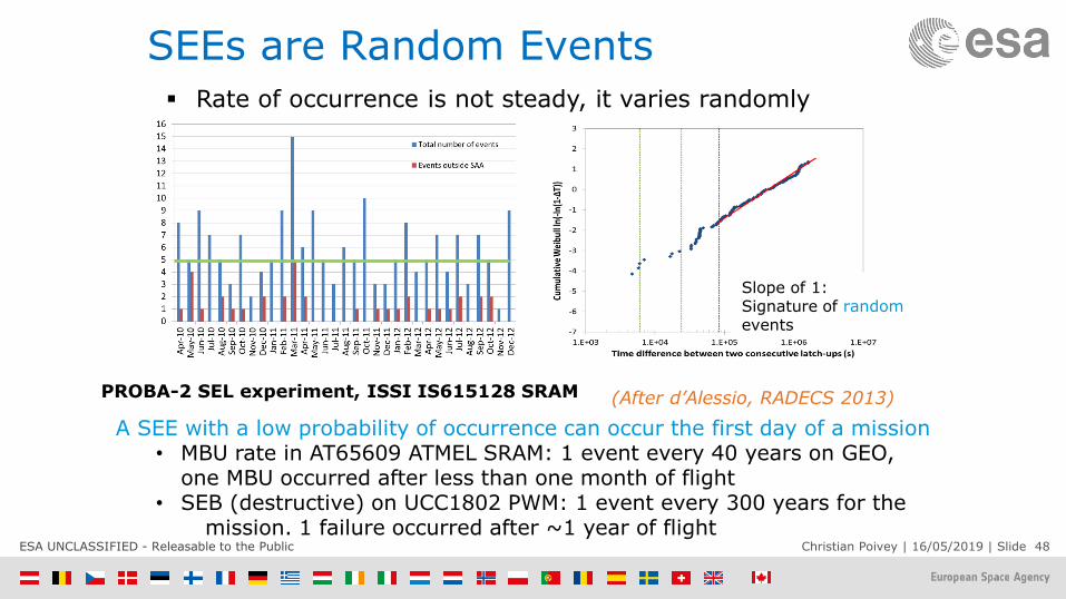
SEEs are Random Events
Slope of 1:Signature of randomevents
(After d’Alessio, RADECS 2013)
Rate of occurrence is not steady, it varies randomly
A SEE with a low probability of occurrence can occur the first day of a mission• MBU rate in AT65609 ATMEL SRAM: 1 event every 40 years on GEO,
one MBU occurred after less than one month of flight • SEB (destructive) on UCC1802 PWM: 1 event every 300 years for the
mission. 1 failure occurred after ~1 year of flight
PROBA-2 SEL experiment, ISSI IS615128 SRAM

ESA UNCLASSIFIED - Releasable to the Public Christian Poivey | 16/05/2019 | Slide 49
OUTLINE
• Space radiation environment
• Radiation effects in space electronics
• Total Ionizing Dose
• Total Non Ionizing Dose (Displacement Damage)
• Single Event Effects
• Conclusion

ESA UNCLASSIFIED - Releasable to the Public Christian Poivey | 16/05/2019 | Slide 50
Conclusion Radiation effects on electronics in space have a direct impact on the
reliability and availability of a system and, therefore, on the success of a mission.
Radiation Hardness Assurance (RHA) process shall be implemented to ensure that the electronics and materials of a space system perform to their design specifications after exposure to the space environment.
The RHA approach on space systems is based on risk management and not on risk avoidance. It requires radiation effect mitigation and tolerant designs.
RHA and radiation engineering require a considerable effort throughout the development of a space system from the early phases of a program development.
50

ESA UNCLASSIFIED - Releasable to the Public Christian Poivey | 16/05/2019 | Slide 51
BACK-UPSLIDES

ESA UNCLASSIFIED - Releasable to the Public Christian Poivey | 16/05/2019 | Slide 52
Displacement Damage, effect of bias during irradiation
Test fluence: 6x10⁹ 10 MeV p/cm2
(Robbins, 2013)

ESA UNCLASSIFIED - Releasable to the Public Christian Poivey | 16/05/2019 | Slide 53
Displacement Damage, effect of bias during annealing
Dark signal annealing, clockedDark signal annealing, unbiased
(Robbins, 2013)

ESA UNCLASSIFIED - Releasable to the Public Christian Poivey | 16/05/2019 | Slide 54
GCRs, Anti-Correlation with Solar Cycle

ESA UNCLASSIFIED - Releasable to the Public Christian Poivey | 16/05/2019 | Slide 55
Destructive Events, SEB and SEGR
Single Event Burnout on a 200V Schottky diode (J.S. George, 2013)
Single Event Gate Rupture in a power MOSFET (Pakarinen 2009)
ESA UNCLASSIFIED - Releasable to the Public Christian Poivey | 16/05/2019 | Slide 56
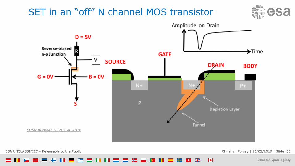
SET in an “off” N channel MOS transistor
(After Buchner, SERESSA 2018)

ESA UNCLASSIFIED - Releasable to the Public Christian Poivey | 16/05/2019 | Slide 57
SET in CMOS inverter
(After Buchner, SERESSA 2018)

ESA UNCLASSIFIED - Releasable to the Public Christian Poivey | 16/05/2019 | Slide 58
Upset in CMOS SRAM
5V
DATA = 1
5V0V
0
0V5V
• Two sensitive nodes for this SRAM cell – OFF n-channel and OFF p-channel transistors.
• Competition between upset (Iseu) andrestoring (Ir) currents
• If charge deposited by ion over a time period comparable to the response time of the circuit exceeds Qcrit an SEU will occur
• Qcritical depends on circuit parameters -parasitic resistance and capacitance
• Qcoll depends on amount of deposited charge and on device structure
Ir
Iseu
SEU if Qcoll > Qcritical
(After Buchner, SERESSA 2018)

ESA UNCLASSIFIED - Releasable to the Public Christian Poivey | 16/05/2019 | Slide 59
5V
Vin = 0V0
5V5V 5V D-Flip-flop clock-edgetriggered
Clock
1
Transient Propagation in Logic Circuits

ESA UNCLASSIFIED - Releasable to the Public Christian Poivey | 16/05/2019 | Slide 60
- Charge moving to a sensitive node is equivalent to current flow at that node. Will alter the
voltage on that node
- Current transient has fast (drift) and slow (diffusion) components – faster than circuit
response
- Total collected charge is integral over time of current = Qcoll (Qdep > Qcoll)
- Qcrit is a circuit parameter that depends on capacitance, voltage, etc.
- If Qcol > Qcrit an SEE will occur
Charge collection
• Amplitude depends on LET of ion, magnitude of E, capacitance of node,…
• Width depends on diffusion component, capacitance of node, charge trapping

ESA UNCLASSIFIED - Releasable to the Public Christian Poivey | 16/05/2019 | Slide 61
RHA Overview – ECSS-Q-ST-60-15C
MISSION/SYSTEM
REQUIREMENTS
SYSTEM AND
CIRCUIT DESIGN
RADIATION
ENVIRONMENT
DEFINITION
PARTS AND
MATERIALS
RADIATION
SENSITIVITY
RADIATION
LEVELS WITHIN
THE SPACECRAFT
ANALYSIS OF THE CIRCUITS, COMPONENTS, SUBSYSTEMS AND
SYSTEM RESPONSE TO THE RADIATION ENVIRONMENT

ESA UNCLASSIFIED - Releasable to the Public Christian Poivey | 16/05/2019 | Slide 62
TNID, bounding part response - NIEL
Solar array
(power loss)
max
TT.LNIEL(E)
T
Td
dTT
s
10-4 10-3 10-2 10-1 100 101 102 103
Particle Energy (MeV)
10-6
10-5
10-4
10-3
10-2
10-1
100
101
Si N
IEL
(M
eV
cm
2/g
)
Proton
Electron
Neutron
*Td = 21 eV
Si
• Rate at which energy is lost to displacement
• Analogous to LET or stopping power for ionizing irradiation
• Unit MeV.cm²/g
• Depends on the target material, the particle type and energy
• NIEL is a mean parameter
• The displacement damage dose (DDD) is the product of the NIEL and the fluence
• For a spectrum of energy
max
min
ENIELDDD
E
E
dEE
Differential cross section
Lindhardt fraction
(in MeV/g)

ESA UNCLASSIFIED - Releasable to the Public Christian Poivey | 16/05/2019 | Slide 63
Power MOSFETs, SEE Safe Operating Area, Example
IRHMB57260SE 200V NMOSFET
Manufacturer’s data with short range ionsJPL data with long range ions
(L. Scheick, NSREC DW 2009)

ESA UNCLASSIFIED - Releasable to the Public Christian Poivey | 16/05/2019 | Slide 64
Displacement damage - Mechanism
- For protons in Si at energies below 10 MeV, Si atoms are displaced from their lattice position via Coulomb interaction
- As the energy of the proton increases the energy transferred from the colliding proton with a Si atom occurs via nuclear elastic interaction.
- More energy is transferred to the recoil atom which again can go on and create additional recoil atoms and hence defect cascades.
- With even higher proton energies the probability of nuclear interaction increases. Many sub cascades may be generated.
64
(Wood 1981)
6 -10 MeV >20 MeV
Defect
Cascades
1 – 2 keV 10-20keV
Energy of recoil (PKA spectrum) is determinedby collision kinematics

ESA UNCLASSIFIED - Releasable to the Public Christian Poivey | 16/05/2019 | Slide 65
Displacement Damage Factor
• Final concentration of defects depends only on NIEL (total energy that goes into
displacements, about 0.1% of total energy loss) and not on the type an initial energy of
the particle
Number of displacements (I-V pairs) is proportional to PKA energy
- Kinchin-Pease: N=T/2TD; T: PKA energy; TD: threshold energy to create a Frenkel pair)
In cascade regime the nature of the damage does not change with particle energy-
just get more cascades
- nature of damage independent of PKA energy
- It is assumed that underlying electrical effect proportional to defect
concentration (Shockley Read Hall theory)
Damage constant depends on device and parameter measured
damage = kdamage x Displacement Damage Dose
dEdE
EdENIEL
)()(

ESA UNCLASSIFIED - Releasable to the Public Christian Poivey | 16/05/2019 | Slide 66
- Only a small fraction of memory (<<1%) show
ISB behavior (retention time degraded by
several orders of magnitude)
- More ISB can appear after the end of the
irradiation
- But some will anneal
- Temperature dependence
- Number of ISB is also dependent of refresh
period
- Stuck bit were initially not considered because
of their small number (compared to SEU and
even SEFI) and it was (wrongly) assumed that
they all anneal quickly
Stuck bits are very difficult to characterize
80 MeV protons, final fluence 8.36E10 /cm2, (Rodriguez, 2017)