Radiation Detectors - Bastian Löher Detectors A collaborative homework for the lecture on...
26
Radiation Detectors A collaborative homework for the lecture on measurement methods in nuclear physics. Bitterling, Garc´ ıa, G¨orgen, Holl, Ingenhaag, Lang, L¨ oher, Omet, Vogelmann
-
Upload
nguyendieu -
Category
Documents
-
view
216 -
download
0
Transcript of Radiation Detectors - Bastian Löher Detectors A collaborative homework for the lecture on...

Radiation Detectors
A collaborative homework for the lecture onmeasurement methods in nuclear physics.
Bitterling, Garcıa, Gorgen, Holl, Ingenhaag, Lang, Loher, Omet, Vogelmann
Contents
1 Ionization Chambers 11.1 Utilization of ion chambers for dosimetry . . . . . . . . . . . . 11.2 Charge Migration an Collection . . . . . . . . . . . . . . . . . 21.3 Pulse measuerements in ionization chambers . . . . . . . . . . 31.4 The Frisch grid . . . . . . . . . . . . . . . . . . . . . . . . . . 3
2 Proportional counter 72.1 Differences between proportional counters and Geiger-Muller
counters . . . . . . . . . . . . . . . . . . . . . . . . . . . . . . 72.2 Energy resolution in proportional counters . . . . . . . . . . . 82.3 Types of proportional counters . . . . . . . . . . . . . . . . . . 9
2.3.1 Sealed tube . . . . . . . . . . . . . . . . . . . . . . . . 92.3.2 Continues flow counter . . . . . . . . . . . . . . . . . . 9
2.4 Fill Gases and the effect of different Gases . . . . . . . . . . . 102.5 how big are the effects of amplification and what do they de-
pend on? . . . . . . . . . . . . . . . . . . . . . . . . . . . . . . 122.6 Multiwire Chambers . . . . . . . . . . . . . . . . . . . . . . . 14
2.6.1 Multiwire Proportional Chamnbers . . . . . . . . . . . 142.6.2 Multiwire Drift Chambers . . . . . . . . . . . . . . . . 16
3 Parallel Plate Avalanche Counter 18
4 Time Projection Chamber 19
Literaturverzeichnis 23
II

Chapter 1
Ionization Chambers
Ionization chambers are constructed as chambers containing a gas in be-tween two electrodes of opposite charge. Incident radiation leaves tracks ofcharged particles and free electrons by means of ionization. These chargedparticles and electrons drift to the electrode of opposite charge and arrivingdonate their charge to a current discharging the electrodes. The most simpletype of ionization chamber simply consist of two electrodes and displays theamount of radiation since last recharging of the electrodes by means of anelectrometer, an electrostatic device capable of making voltage differencesvisible. More sophisticated kinds electronically measure the current gener-ated by the charged particles. In order to do this they have to take intoaccount that the total charge in a track of even high energy particles is quitelow, so the current to be measured will be quite small. The geometries of ion-ization chambers show great variance. However to minimize disturbance bycharge exchange between the ionization chamber electrodes by other meansthan ionized particles and their electrons a special geometry of insulation(see figure 1.1) is used.
1.1 Utilization of ion chambers for dosimetry
For direct dose measurement one would require to accumulate all secondaryionization induced by all secondary electrons at the point where the dosewere to be measured. As the mean traveling distance of secondary electronsinduced by typical gamma energies can be several meters, this would requirequite a large ionization chamber. Fortunately, air is usable as a medium forionization chambers. Provided that gamma rays of the energy to be observedare not noteably blocked by air at the observed energy and length scale ofthe dosimeter, one can postulate isotropic generation of secondary electrons
1

ht
Figure 1.1: Insulation in ionization chambers: To minimize the current troughthe resistance of the insulator, a guard ring carrying the same potential as themeasuereing electrode is applied. This way the voltage drop can be restrictedto the outer insulator, and no current through the inner insulator will lead tomisreadings in the current measurement. [1]
in- and outside the ionization chamber. Thus the amount of electrons lostflying out of the chamber will cancel out the amount of produced elsewhereand entering the chamber. By measuring the ionization of radiation in air,the amount of ionization taking place in other materials can be calculatedand thus dosimetry results are possible.
1.2 Charge Migration an Collection
In an electric field ions an electrons will move from their point of origin.Their drift-velocity can be predicted by formula 1.1.
v = µE
p(1.1)
� v : Driftspeed
� µ : Mobility of the particle
� E : Strength of the electric field
� p : Gas pressure
The mean value of the mobility of ions in gases lies between 1 and 1, 5 ·10−4 m2·atm
V ·s . The resulting drift-velocity is of the magnitude of 10 ms whichleads to collection-times of 10 ms. For electrons their smaller mass allows agreater acceleration between interactions with gas molecules. Therefor theirmobility is bigger by a factor of 1000. Accordingly their collection time is ofthe magnitude of microseconds instead of milliseconds.
2

In most cases the drift-velocity increases with higher values of Ep
, but withsome gases a saturation effect comes in to play, which can even lower the drift-velocity after a certain threshold of electric field strength. In an ion chamberthe electrons and ions created through irradiation are collected at the an-ode and cathode and form a electrical current. Losses due to recombinationcan be reduced through strengthening of the electric field until saturation isachieved an every electron produced is collected. The necessary voltage forsaturation is increased by impurity’s of heavy charged particles that recom-bine with electrons on their path. Furthermore strong irradiation increasesthe density of positive charged ions which increases the chance for recombi-nation. Lastly the drift of positive charged ions to the cathode and negativecharged electrons to the anode creates a charge division which electric fieldopposes the original one.
1.3 Pulse measuerements in ionization cham-
bers
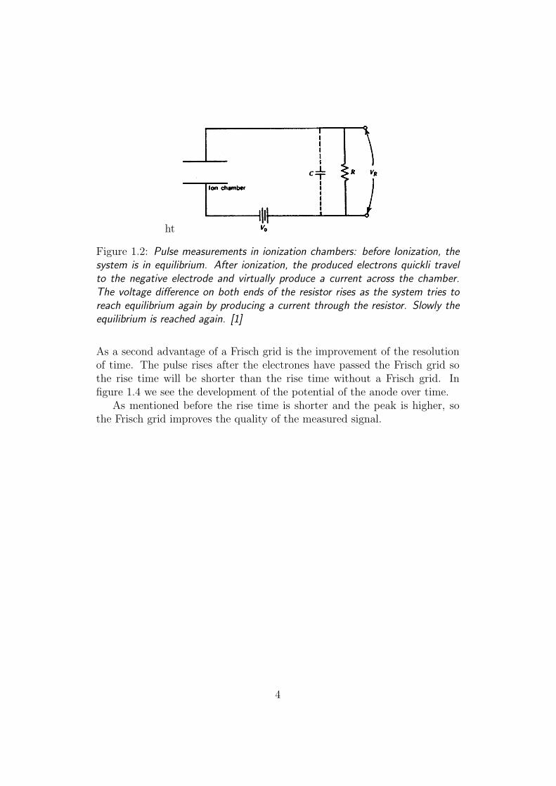
Pulse measurements are possible and explained in 1.2. Chosing the usedresistor and capacity one can chose the time of return to equilibrium. Chos-ing them correctly it is possible to adjust the timescale of the system suchthat either only the produced electrons are measured or the produced ionsare taken into account. Since operated on a timescale of milliseconds theionization chamber is sensitive to acoustic disturbances, in most cases thechambers are operated in the electron sensitive mode.
1.4 The Frisch grid
The Frisch grid is named after the austrian–british physicist Otto RobertFrisch [3].Basically it is a grid made of a conductive material that is typically placedbetween the cathode and anode in ionizationchambers and is commonly onground potential or weakly charged. In figure 1.3 we see a layout of a ion-izationchamber with a frisch grid.
The Frisch grid brings two advantages.The height of a puls measured in a ionizationchamber depends on the locationof the primary ionizsation. So detectors that cover great dihedral angles willhave a bad signal quality. By deflecting the anode with the Frisch grid thedependence of the location of the primary ionization is dramaticly reduced[4].
3
ht
Figure 1.2: Pulse measurements in ionization chambers: before Ionization, thesystem is in equilibrium. After ionization, the produced electrons quickli travelto the negative electrode and virtually produce a current across the chamber.The voltage difference on both ends of the resistor rises as the system tries toreach equilibrium again by producing a current through the resistor. Slowly theequilibrium is reached again. [1]
As a second advantage of a Frisch grid is the improvement of the resolutionof time. The pulse rises after the electrones have passed the Frisch grid sothe rise time will be shorter than the rise time without a Frisch grid. Infigure 1.4 we see the development of the potential of the anode over time.
As mentioned before the rise time is shorter and the peak is higher, sothe Frisch grid improves the quality of the measured signal.
4
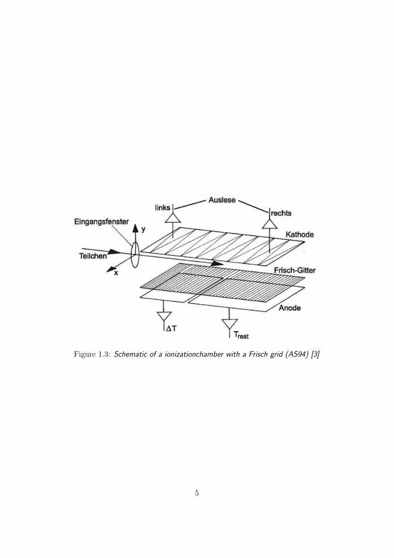
Figure 1.3: Schematic of a ionizationchamber with a Frisch grid (AS94) [3]
5

Figure 1.4: Process of the potential of the anode over time: (a) without (b)with a Frisch grid [4]
6
Chapter 2
Proportional counter
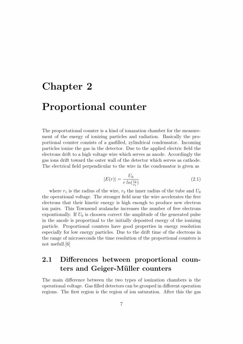
The proportational counter is a kind of ionazation chamber for the measure-ment of the energy of ionizing particles and radiation. Basically the pro-portional counter consists of a gasfilled, zylindrical condensator. Incomingparticles ionize the gas in the detector. Due to the applied electric field theelectrons drift to a high voltage wire which serves as anode. Accordingly thegas ions drift toward the outer wall of the detector which serves as cathode.The electrical field perpendicular to the wire in the condensator is given as
|E(r)| = U0
r ln( r2r1
)(2.1)
where r1 is the radius of the wire, r2 the inner radius of the tube and U0
the operational voltage. The stronger field near the wire accelerates the freeelectrons that their kinetic energy is high enough to produce new electronion pairs. This Townsend avalanche increases the number of free electronsexpontionally. If U0 is choosen correct the amplitude of the generated pulsein the anode is proportinal to the initially deposited energy of the ionizingparticle. Proportional counters have good properties in energy resolutionespecially for low energy particles. Due to the drift time of the electrons inthe range of microseconds the time resolution of the proportional counters isnot usefull.[6]
2.1 Differences between proportional coun-
ters and Geiger-Muller counters
The main difference between the two types of ionization chambers is theoperational voltage. Gas filled detectors can be grouped in different operationregions. The first region is the region of ion saturation. After this the gas
7
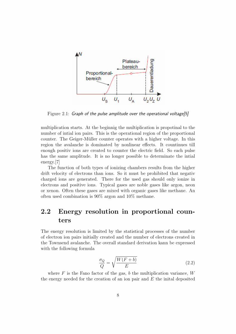
Figure 2.1: Graph of the pulse amplitude over the operational voltage[5]
multiplication starts. At the beginnig the multiplication is propotinal to thenumber of intial ion pairs. This is the operational region of the proportionalcounter. The Geiger-Muller counter operates with a higher voltage. In thisregion the avalanche is dominated by nonlinear effects. It countinues tillenough positiv ions are created to counter the electric field. So each pulsehas the same amplitude. It is no longer possible to determinate the intialenergy.[7]
The function of both types of ionizing chambers results from the higherdrift velocity of electrons than ions. So it must be prohibited that negativcharged ions are generated. There for the used gas should only ionize inelectrons and positive ions. Typical gases are noble gases like argon, neonor xenon. Often these gases are mixed with organic gases like methane. Anoften used combination is 90% argon and 10% methane.
2.2 Energy resolution in proportional coun-
ters
The energy resolution is limited by the statistical processes of the numberof electron ion pairs initially created and the number of electrons created inthe Townsend avalanche. The overall standard derivation kann be expressedwith the following formula
σQQ
=
√W (F + b)
E(2.2)
where F is the Fano factor of the gas, b the multiplication variance, Wthe energy needed for the creation of an ion pair and E the inital deposited
8

Figure 2.2: Schematic of a sealed tube proportional counter[6]
energy. Typical values for the values for the energy resolution are between10 and 15 %.[7]
2.3 Types of proportional counters
There are different types of proportinal counters which serve different needs.Two types are presented as examples.
2.3.1 Sealed tube
Sealed tubes are normally zylinders. The gas is sealed in the tube. A windoweither on one end of the tube or in the outer cathode wall. Advantages of thistype are its transpotability as it only needs a power source and good energyresolution due to the axial uniform electric field. Disadvantages of this designare that the lifetime is limited due to microleaks in the tube and the needfor a casing. The first results in the contamination of the gas through othergases, e.g. air which produces negative ions. The later disadvatange lowersthe effectivness of the detector in the measurement of larger particles, e.g.α-particles, because they cannot pass through the casing.[7]
2.3.2 Continues flow counter
A problem of sealed counters is that ionizing particles must pass throughan outer casing. Especially for α-particles this can be problematic. Thisproblem is solved by placing the sample in the detector. Also the otherproblem of a sealed tube can be solved with the current flow counter. Thesample is placed inside an hemispherical chamber. The gas is slowly pumped
9
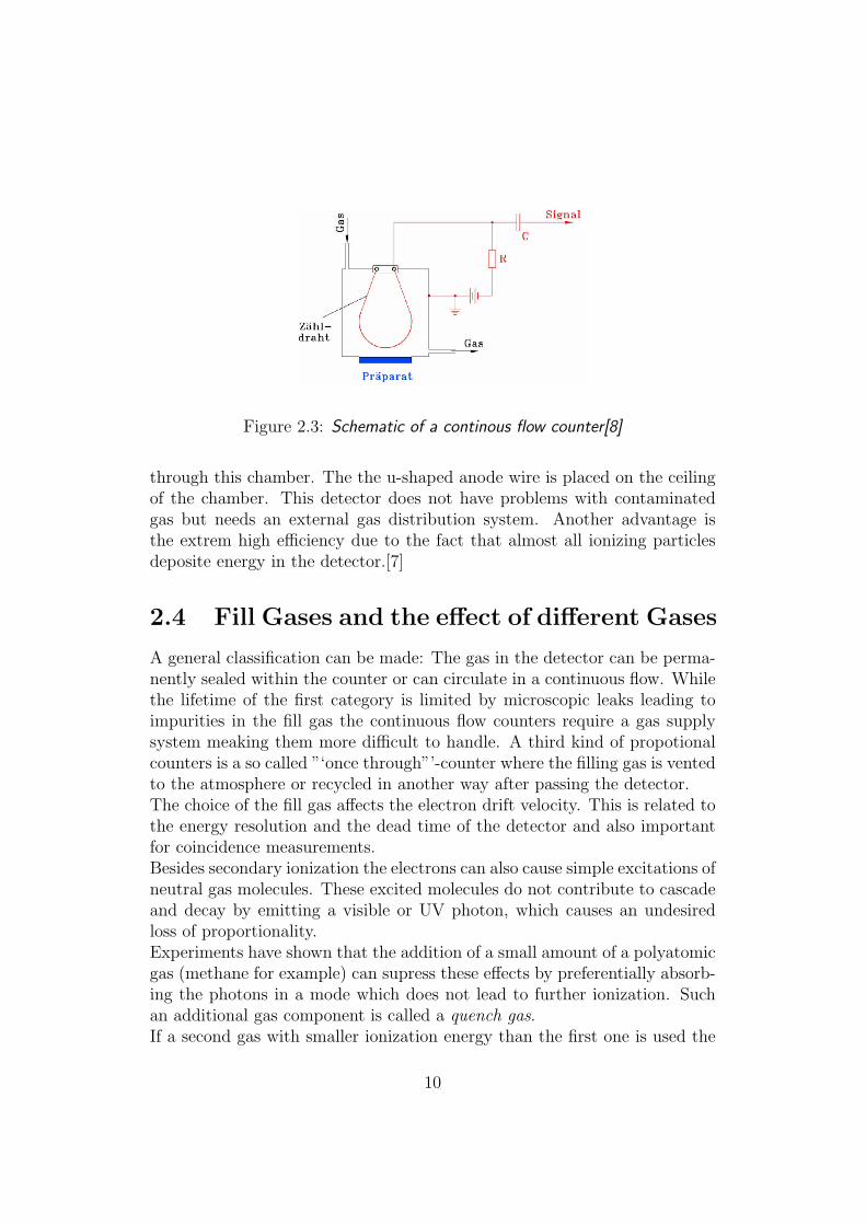
Figure 2.3: Schematic of a continous flow counter[8]
through this chamber. The the u-shaped anode wire is placed on the ceilingof the chamber. This detector does not have problems with contaminatedgas but needs an external gas distribution system. Another advantage isthe extrem high efficiency due to the fact that almost all ionizing particlesdeposite energy in the detector.[7]
2.4 Fill Gases and the effect of different Gases
A general classification can be made: The gas in the detector can be perma-nently sealed within the counter or can circulate in a continuous flow. Whilethe lifetime of the first category is limited by microscopic leaks leading toimpurities in the fill gas the continuous flow counters require a gas supplysystem meaking them more difficult to handle. A third kind of propotionalcounters is a so called ”‘once through”’-counter where the filling gas is ventedto the atmosphere or recycled in another way after passing the detector.The choice of the fill gas affects the electron drift velocity. This is related tothe energy resolution and the dead time of the detector and also importantfor coincidence measurements.Besides secondary ionization the electrons can also cause simple excitations ofneutral gas molecules. These excited molecules do not contribute to cascadeand decay by emitting a visible or UV photon, which causes an undesiredloss of proportionality.Experiments have shown that the addition of a small amount of a polyatomicgas (methane for example) can supress these effects by preferentially absorb-ing the photons in a mode which does not lead to further ionization. Suchan additional gas component is called a quench gas.If a second gas with smaller ionization energy than the first one is used the
10
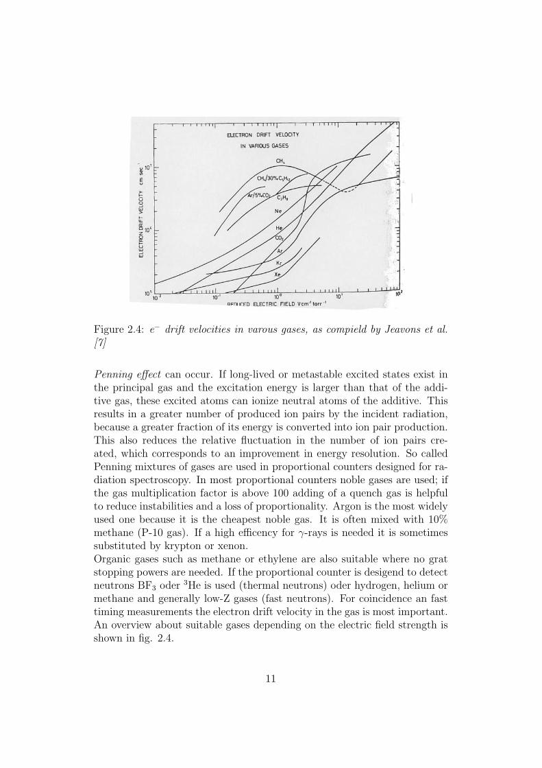
Figure 2.4: e− drift velocities in varous gases, as compield by Jeavons et al.[7]
Penning effect can occur. If long-lived or metastable excited states exist inthe principal gas and the excitation energy is larger than that of the addi-tive gas, these excited atoms can ionize neutral atoms of the additive. Thisresults in a greater number of produced ion pairs by the incident radiation,because a greater fraction of its energy is converted into ion pair production.This also reduces the relative fluctuation in the number of ion pairs cre-ated, which corresponds to an improvement in energy resolution. So calledPenning mixtures of gases are used in proportional counters designed for ra-diation spectroscopy. In most proportional counters noble gases are used; ifthe gas multiplication factor is above 100 adding of a quench gas is helpfulto reduce instabilities and a loss of proportionality. Argon is the most widelyused one because it is the cheapest noble gas. It is often mixed with 10%methane (P-10 gas). If a high efficency for γ-rays is needed it is sometimessubstituted by krypton or xenon.Organic gases such as methane or ethylene are also suitable where no gratstopping powers are needed. If the proportional counter is desigend to detectneutrons BF3 oder 3He is used (thermal neutrons) oder hydrogen, helium ormethane and generally low-Z gases (fast neutrons). For coincidence an fasttiming measurements the electron drift velocity in the gas is most important.An overview about suitable gases depending on the electric field strength isshown in fig. 2.4.
11
2.5 Effects of amplification
The electric field is strong enough to accelerate freed electrons to an energywhere they are also capable of ionizing gas molecules in the cylinder. Theelectrons liberated in these secondary ionizations, of course are also acceler-ated to produce still more ionization and so on. This results in an ionizatonTownsend avalanche [10].If the operating voltage is chosen carefully, each avalanche process occursindependently of other avalanches which derive from the same initial ioniz-ing event. Therefore, even though the total number of electrons liberatedcan increase exponentially with distance, the total amount of charge createdremains proportional to the amount of charge liberated in the original event.The geometry of the electrodes and the voltages on them are chosen suchthat in most of the volume of the counter the electric field strength is notenough to produce a Townsend avalanche. The electrons just drift until theyget close to the anode, where a strong field allows avalanche multiplicationto occur. In this way each electron is multiplied by approximately the samefactor (up to about a million) independent of the distance it has covered inthe low-field ’drift region’. If the field strength everywhere is below a criticalvalue, Townsend avalanches do not occur at all, and the detector operates asan ionization chamber. If the voltage (and therefore the field strength) is toohigh, the degree of charge amplification tends to a maximum value, and allpulses from the chamber have the same amplitude, so the detector operatesas a Geiger-Mller counter. [11]Because of the greater movility of the electrons, the avalanche has the formof a liquid-drop with the electrons grouped near the head and the slower ionstrailing behind.If α is the mean free path of the electron for a secondary ionizing collision,then α is the probability of an ionization per unit path length. This is betterknown as the first Townsend cofficient. If there are n electrons, then in apath dx, there will be
dn = nαdx (2.3)
new electrons created. Integrating, this yields the total number of electronscreated in a path x,
n = n0exp(αx) (2.4)
where n0 is the original number of electrons. The multiplication factor isthen
M = n/n0 = exp(αx). (2.5)
12
Physically, the multiplication factor is limed to about M < 108 or αx < 20after which breakdown occurs. This is known as the Raether limit. Themultiplication factor or gas gain is of fundamental importance for the devel-opment of proportional counters. For this reason, various theorical modelshave been developed for calculation α for different gases. A very early modelby Rose and Korff, for example gives
α
p= A exp
(−BpE
)(2.6)
where A and B are constants depending on the gas.In figure 2.5 is shown different issues. In the part called FIG.1 shown a cross-sectional view of a proportional counter tube. In FIG.2 illustrates the after-pulsing phenomena with a pure xenon-filled tube as described in connectionwith FIG.1. In this particular case, the incident radiation was manganeseK-alpha with an energy content of 5.9 keV, and potentials of 1850 V, 1900 Vand 1950 V were applied to the tube in succesion, producing on the face ofan oscilloscope coupled to the output of the porportional counter the threepulse patterns illustred in FIGS. 2a, 2b and 2c, respectively.
13
2.6 Multiwire Chambers
2.6.1 Multiwire Proportional Chamnbers
In Multiwire Proportional Chambers (MWPC) the principles of the propor-tional counter are applied to large-scale detectors. MWPCs consist of asurface of anode wires that are placed parallel between two cathode plates.A scheme of such a detector is shown in figure 2.6. The distances betweenthe wires are typically ≈ 2 mm and the distance between the wires and thecathodes is 3- to 4-times that long.
By applying a high voltage between the wires and the cathodes one ob-tains an electrostatic field that is nearly identical to the one of cylindricalcapacitor in the vicinity of the wires and almost homogenous near the cath-odes. The electrical field inside a MWPC and its equipotential lines aredepicted in figure 2.7.
Electrons released by the incoming particles drift towards the nearestwire. Each wire behaves as a proportional counter and is read out individ-ually. The charge accumulating on the anode wires determines the pulseheight, and depends on the gas used, the voltage applied, and geometricalparameters of the chamber. The pulse height is a measure of the energy lossof the particles in the gas and can therefore be used for particle or momen-tum identification.
The MWPCs can also be used to measure the trajectory of a particle. Thecoordinate perpendicular to the direction of the wires can be determined byidentifying the anode which detected the particle. However, if the path of aparticle is not parallel to the detector plane, more than one of the wires willdetect it. This is called cluster formation and is shown in figure 2.8. In thiscase, algorithms have to be used to determine the exact position.
To also obtain the coordinate parallel to the wires there are differenttechniques:
� Several planes of anode wires with different orientations can be used.
� The signales of the cathodes, which in these cases have to be arrangedas pads or as stripes perpendicular to the wires, can be read out aswell.
� The signals of the anodes can be read out from both sides. By com-paring the pulse heights on both sides the exact position the particle
14

Figure 2.5: Scheme of a proportional counter and results from experiments.(source: [9])
15

Figure 2.6: Diagram of a Multiwire Proportional Chamber. [13]
was detected can be determined.
Multiwire Proportional Chambers have extremely high detection efficien-cys of nearly 100 %.
2.6.2 Multiwire Drift Chambers
Multiwire drift chambers are similar to MWPCs, however, the position of aparticle is determined by the drift time the electrons take until they reachthe anodes. The entire chamber is divided into a drift region, in which theelectrical field is homogeneous, and the amplifying region. This done withthe help of a grid which is set to a constant potential.
Incoming particles cause the production of free electrons. These movewith a velocity of typically ≈ 50µm
nsin direction of the electrical field through
the drift region, before they enter the amplifying region where they causesecondary ionisations. To determine the time of the primary ionisation de-tectors with a fast response time, e.g. scintillators are used.
The advantage of this kind of detectors compared to MWPCs is that thespatial resolution does not depend on the distance between the wires. Also,since there are fewer wires, the mechanical stability is higher. However, sinceit takes the electrons some time to drift towards the wires, the reaction timeof the Drift Chambers is not as good as the one of MWPCs.
16
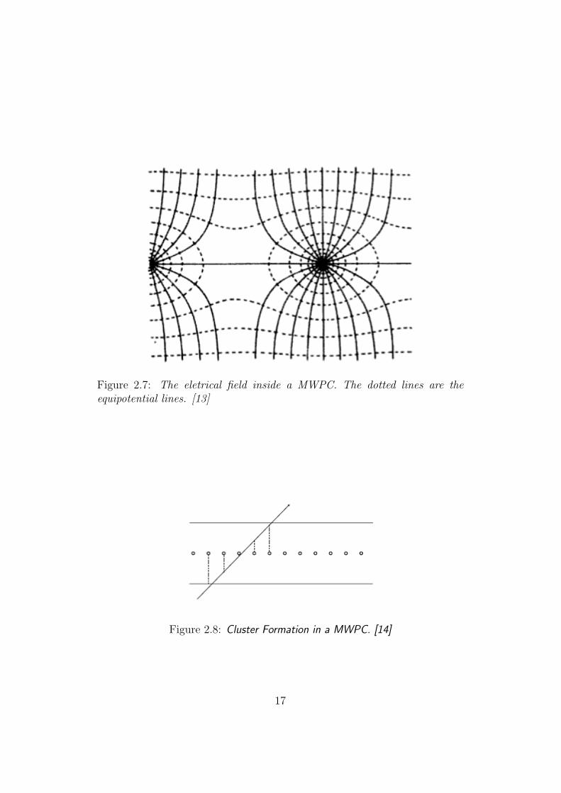
Figure 2.7: The eletrical field inside a MWPC. The dotted lines are theequipotential lines. [13]
Figure 2.8: Cluster Formation in a MWPC. [14]
17

Chapter 3
Parallel Plate AvalancheCounter
The parallel plate avalanche detector is particularly useful in applicationsinvolving heavy charged particles where the associated radiation damage insolid-state detectors may prohibit their use. The parallel plate avalanchecounter (PPAC) consists of two parallel plate electrodes separated by a gapthat is kept as small as possible for best timing information. An other config-uration use fine mesh grids instead of solid plates to reduce their thickness.The electrodes are enclosed in a container in wich a proportional gas is intro-duced and a homogeneous electric field is produced between the plates whichare under conditions of relatively low gas pressure.If a charged particle cross the gap between the plates, it leaves a trail ofions and electrons which are multiplied through the usual gas multiplicationprocess. The electrons formed nearest the cathode are obviously subjected tomore multiplication than those formed near the anode. Maximum gas gainsof the order of 104 are possible.Because any typical output pulse contains a mix of gas amplification factors,the energy resolution is seldom better than about 20%. Nonetheless, thisperformance is often adequate to separate different types of particles withwidely different specific energy loss. The parallel plate avalanche detectorcan also be made to yield two-dimensional position information by usingappropriately patterned electrodes.[7]
18
Chapter 4
Time Projection Chamber
In many experiments around the world it is of great importance to determineseveral properties of charged particles from collisions in a single detector. Forsimultaneous particle identification and momentum measurement the timeprojection chamber is a useful device. The most prominent installations ofthis kind of detectors can be found at RHIC (STAR TPC)[15] and at CERN(ALICE TPC)[16].
A typical TPC design consists of a large barrel shaped gas container,which holds the drift gas. It is installed around the beam line at the in-tersection point, where particle collisions take place. In the barrel a highvoltage is applied between a center membrane and the barrel end caps, sothat a uniform electric field gradient is created. The end caps of the TPChold the actual particle detectors. An additional magnetic field can be in-troduced by wrapping the time projection chamber in a solenoidal magnet.In fig. 4.1 a schematic drawing of the STAR TPC at RHIC is shown.
In order to identify particles and determine their momentum, the exacttrajectories of the particles from the intersection point through the TPC haveto be reconstructed. From the shape of these tracks, which are in first orderapproximation of helical geometry (cf. fig. 4.2), the particle momentum canbe derived. Taking into account second order effects like ionization energyloss per unit length also allows to identify particle types.
For accurate particle tracking several points in space must be recorded foreach trajectory, so that a model path can be fitted to these points. The threecoordinates for each point are determined by different mechanisms. Lets as-sume cylindrical coordinated where the z axis is pointing longitudinally alongthe beam line and the angle θ describes the azimuthal direction. The r coor-dinate is measured with respect to the distance from the beam pipe. Whena charged particle from a collision traverses the barrel, gas atoms are ionizedalong its path. The applied electric field accelerates the electrons towards the
19

Figure 4.1: Schematic drawing of the STAR TPC at RHIC. It surrounds thebeam-beam interaction region. The collisions take place near the center of theTPC.[15]
end caps of the barrel. Specialized MWPC (Multi wire proportional coun-ters) detectors with high spatial resolution and accurate timing are used todetermine the r and θ coordinates directly. To gain information about thelongitudinal distance, the drift time of ionized electrons from their origin tothe end cap detectors is measured and then divided by an average drift timefor electrons in the setup. In the case of the STAR TPC the employed driftgas is P10 (a mixture of 90% argon and 10% methane) with an average driftvelocity of 5.45 cm/µs.
Particle momentum can be determined by fitting circles through the r andθ coordinates of the intersection point and the data points along a particle’strajectory. The radius of the circle and its angle with respect to the beamline then hold information about the particle momentum dependent on theapplied magnetic field.
For particle identification the energy that the particles lose to the TPCgas is measured along their trajectory. This results in a characteristic valueof dE/dx for each type of particle. This identification using TPCs is onlypossible in the low momentum range, as can be seen in fig. 4.3. Protons andpions can be seperated from each other up to 1 GeV/c.
The tracking resolution is limited by the spacing of the wires and padsin the MWPCs as well as by transverse and longitudinal diffusion of the
20

Figure 4.2: Simulated event in the ALICE TPC. Reconstructed particle trackswith their typical shape are displayed. Source: http://www.gled.org
secondary electrons in the drift gas. Also the deviations from uniformity ofthe magnetic field cause tracking errors. Very careful design and calibrationof the detector minimize these effects. Several less important effects likespace charge or realistic geometrical shapes have to be taken into accountas well. For the STAR TPC the overall tracking efficiency is above 70% forparticle momenta above 300 MeV/c.
21

Figure 4.3: The energy loss distribution for primary and secondary particles inthe STAR TPC as a function of the momentum of the primary particle. Themagnetic field here was 0.25 T.[15]
22

Bibliography
[1] Wiley & Sons: Glenn F. Knoll, Radiation Detecion and Measurement(2000) 129-157, ISBN-10 0-471-07338-5
[2] Radiation Detection and Measurement(Author: G.F. Knoll)(ISBN:0471073383)(Verlag: Wiley, 2000)
[3] Klaus Bethge, Gertrud Walter, Bernhard Wiedemann, Springer (2007)
[4] Adrian Gohla, Aufbau eines Detektorteleskops fur ERDA–Messungenund erste Anwendungen auf dunne Schichten, Rheinische Friedrich–Wilhelms–Universitat, Bonn (1994)
[5] Springer: H. J. Eichler, H.-D. Kronfeldt, J. Sahm, Das Neue Physikalis-che Grundpraktikum (2006) 514-515, ISBN-10 3-540-21453-4
[6] Springer: Christoph Berger, Elementarteilchenphysik (2006) 69-71,ISBN-10 3-540-23143-9
[7] Wiley & Sons: Glenn F. Knoll, Radiation Detecion and Measurement(2000) 160-178, ISBN-10 0-471-07338-5
[8] Universitat Freiburg, Physikalisches Fortgeschrittenen Praktikum,Kapitel 2.3, http://wwwhep.physik.uni-freiburg.de/fp/Versuche/FP1-7-LangeHalbwertzeiten/StaatsexArbeitKapitel/PDFs/Kapitel2.3-Proportionalzaehler.pdf
[9] E. W. Molloy, Air proportional counter, U.S. Patent 2,499,830.
[10] W. R. Leo Techniques for Nuclear and Particle Physics Expereriments,Springer-Verlag Berlin Heidelberg 1987.
[11] http://en.wikipedia.org/wiki/Proportionalcounter.
[12] R.K. Bock, A. Vasislescu, The Particle Detector BriefBook (InternetVersion), www.rkb.home.cern.ch/rkb/titleD.html
23

[13] Konrad Kleinknecht, Detektoren fur Teilchenstrahlung, S.63-70 (2005)
[14] H. Kolanoski, Detektoren in der Elementarteilchenphysik, Humboldt-Universitat zu Berlin, S.79-114 (2007)
[15] M. Anderson, Nuclear Instruments and Methods in Physics Research A499 (2003) 659-678
[16] P. Gl”assel, Nuclear Instruments and Methods in Physics Research A572 (2007) 64-66
24