
Radiation Detection and Counting Statistics Please Read: Chapters 3 (all 3 parts), 8, and 26 in...
105
Radiation Detection and Counting Statistics Please Read: Chapters 3 (all 3 parts), 8, and 26 in Doyle
-
Upload
gabriella-skinner -
Category
Documents
-
view
214 -
download
0
Transcript of Radiation Detection and Counting Statistics Please Read: Chapters 3 (all 3 parts), 8, and 26 in...

Radiation Detection and Counting Statistics
Please Read: Chapters 3 (all 3 parts), 8, and 26 in Doyle

Types of Radiation
• Charged Particle Radiation– Electrons
• particles
– Heavy Charged Particles• particles
• Fission Products
• Particle Accelerators
• Uncharged Radiation– Electromagnetic Radiation
• -rays
• x-rays
– Neutrons• Fission, Fusion reactions
• Photoneutrons
Can be easily stopped/shielded!
More difficult to shield against!

Penetration Distances for Different Forms of Radiation
’s
’s
’s
n’s
Paper Plastic (few cm)
Lead(few in)
Concrete(few feet)

Why is Radiation Detection Difficult?
• Can’t see it• Can’t smell it• Can’t hear it• Can’t feel it• Can’t taste it
• We take advantage of the fact that radiation produces ionized pairs to try to create an electrical signal

Ideal Properties for Detection of Radioactivity
Radiation Ideal Detector Properties Very thin/no window or
ability to put source insidedetector
Same as above, can be low orhigh density, gas, liquid, or
solid High density, high atomic
number materialsneutrons Low atomic number materials,
preferably hydrogenous
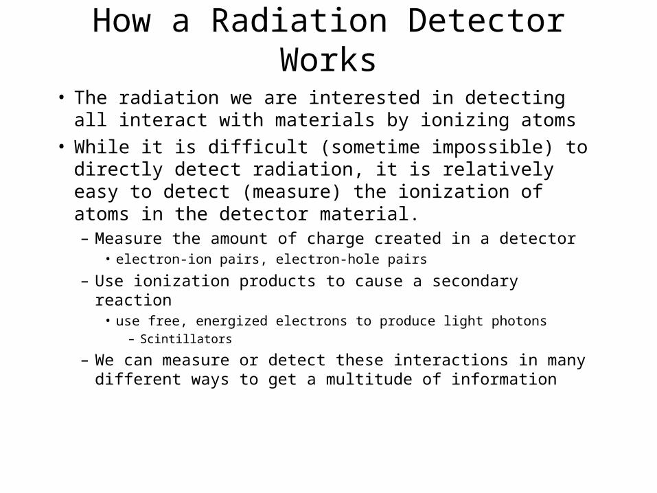
How a Radiation Detector Works
• The radiation we are interested in detecting all interact with materials by ionizing atoms
• While it is difficult (sometime impossible) to directly detect radiation, it is relatively easy to detect (measure) the ionization of atoms in the detector material.– Measure the amount of charge created in a detector
• electron-ion pairs, electron-hole pairs
– Use ionization products to cause a secondary reaction• use free, energized electrons to produce light photons
– Scintillators
– We can measure or detect these interactions in many different ways to get a multitude of information

General Detector Properties
• Characteristics of an “ideal” radiation detector– High probability that radiation will interact with the detector
material– Large amount of charge created in the interaction process
• average energy required for creation of ionization pair (W)
– Charge must be separated an collected by electrodes• Opposite charges attract, “recombination” must be avoided
– Initial Generated charge in detector (Q) is very small (e.g., 10-
13C)• Signal in detector must be amplified
– Internal Amplification (multiplication in detector)– External Amplification (electronics)
• Want to maximize V C
QV
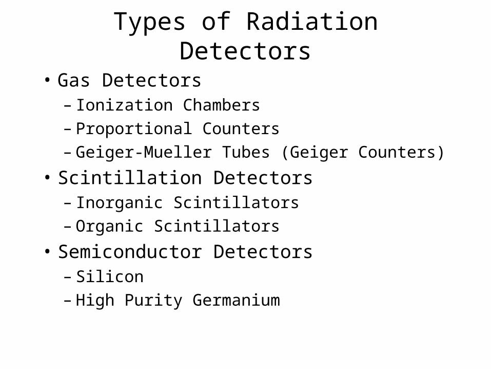
Types of Radiation Detectors
• Gas Detectors– Ionization Chambers– Proportional Counters– Geiger-Mueller Tubes (Geiger Counters)
• Scintillation Detectors– Inorganic Scintillators– Organic Scintillators
• Semiconductor Detectors– Silicon– High Purity Germanium
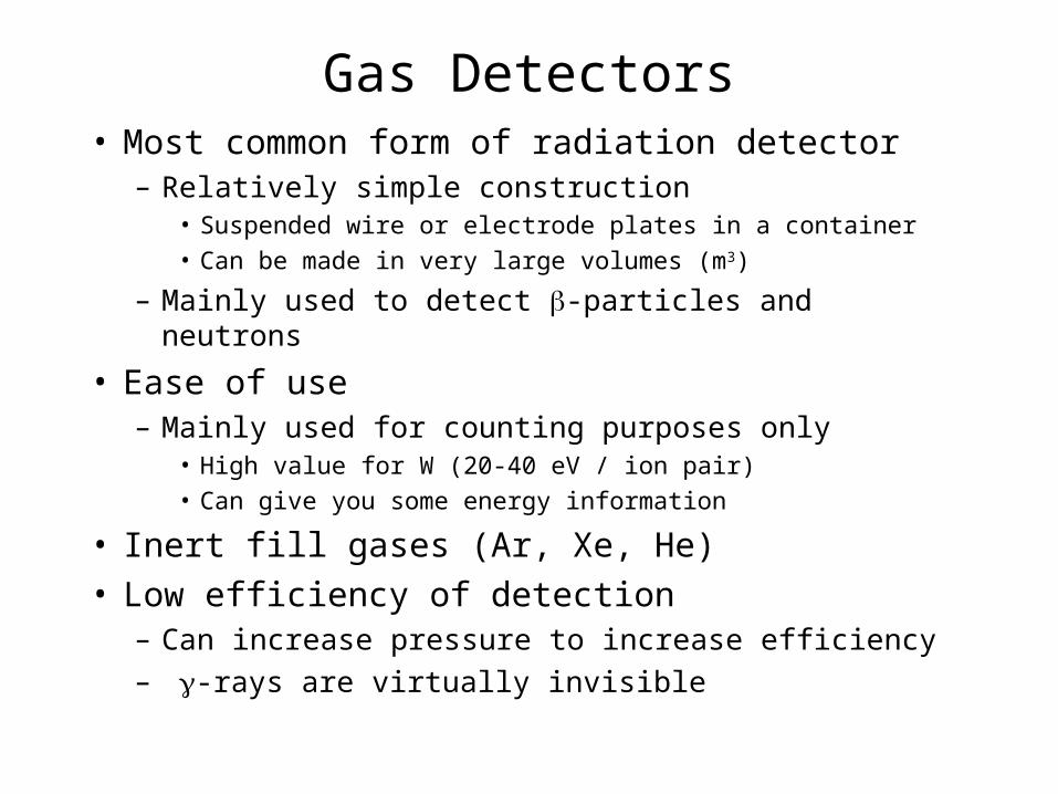
Gas Detectors• Most common form of radiation detector
– Relatively simple construction• Suspended wire or electrode plates in a container• Can be made in very large volumes (m3)
– Mainly used to detect -particles and neutrons
• Ease of use– Mainly used for counting purposes only
• High value for W (20-40 eV / ion pair)• Can give you some energy information
• Inert fill gases (Ar, Xe, He)• Low efficiency of detection
– Can increase pressure to increase efficiency
– -rays are virtually invisible

Ionization Chambers
• Two electric plates surrounded by a metal case
• Electric Field (E=V/D) is applied across electrodes
• Electric Field is low– only original ion pairs created
by radiation are collected– Signal is very small
• Can get some energy information– Resolution is poor due to
statistics, electronic noise, and microphonics
Good for detecting heavy charged particles, betas
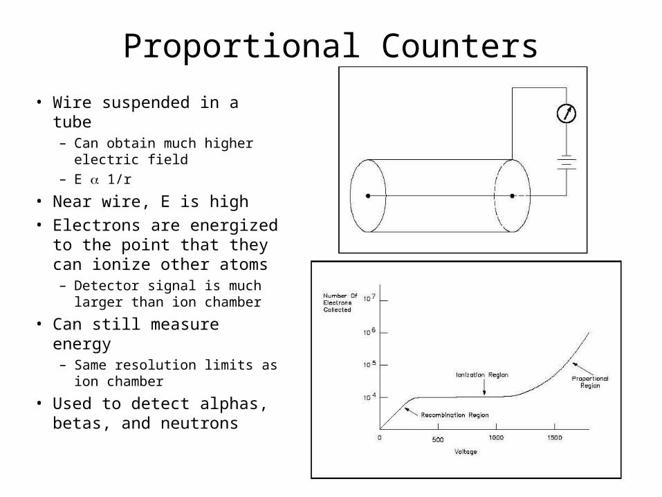
Proportional Counters
• Wire suspended in a tube– Can obtain much higher
electric field– E 1/r
• Near wire, E is high• Electrons are energized to the
point that they can ionize other atoms– Detector signal is much larger
than ion chamber
• Can still measure energy– Same resolution limits as ion
chamber
• Used to detect alphas, betas, and neutrons
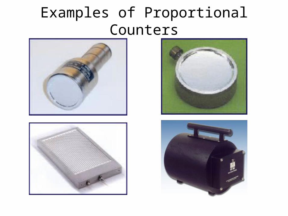
Examples of Proportional Counters

Geiger Counters
• Apply a very large voltage across the detector– Generates a significantly higher
electric field than proportional counters
– Multiplication near the anode wire occurs
• Geiger Discharge• Quench Gas
• Generated Signal is independent of the energy deposited in the detector
• Primarily Beta detection• Most common form of
detector
No energy information! Only used to count / measure the
amount of radiation. Signal is independent of type of
radiation as well!

Examples of Geiger Counters
Geiger counters generally come in compact, hand carriedinstruments. They can be easily operated with battery power and are usually calibrated to give you radiation dose measurements in rad/hr or rem/hr.

Scintillator Detectors
• Voltage is not applied to these types of detectors• Radiation interactions result in the creation of light
photons– Goal is to measure the amount of light created– Light created is proportion to radiation energy
• To measure energy, need to convert light to electrical signal– Photomultiplier tube– Photodiode
• Two general types– Organic– Inorganic
} light electrons

Organic Scintillators
• Light is generated by fluorescence of molecules
• Organic - low atomic numbers, relatively low density– Low detection efficiency for gamma-rays
• Low light yield (1000 photons/MeV) - poor signal– Light response different for different types of radiation
• Light is created quickly– Can be used in situations where speed (ns) is necessary
• Can be used in both solid and liquid form– Liquid form for low energy, low activity beta monitoring,
neutrino detection
– Very large volumes (m3)
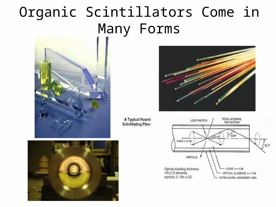
Organic Scintillators Come in Many Forms

Inorganic Scintillators
• Generally, high atomic number and high density materials– NaI, CsI, BiGeO, Lithium glasses, ZnS
• Light generated by electron transitions within the crystalline structure of the detector– Cannot be used in liquid form!
• High light yield (~60,000 photons / MeV)– light yield in inorganics is slow (s)
• Commonly used for gamma-ray spectroscopy– W ~ 20 eV (resolution 5% for 1 MeV -ray)– Neutron detection possible with some
• Can be made in very large volumes (100s of cm3)
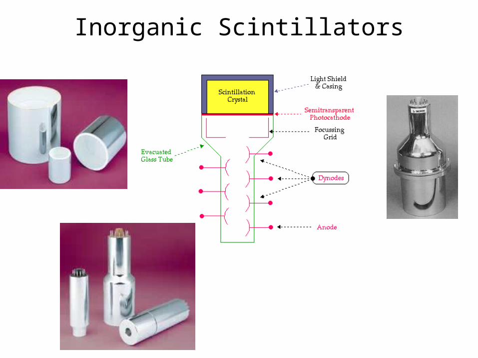
Inorganic Scintillators

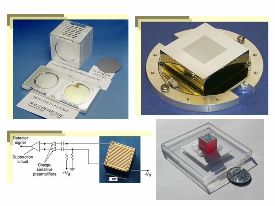
Solid State (Semiconductor) Detectors• Radiation interactions yield electron-hole pairs
– analogous to ion pairs in gas detectors
• Very low W-value (1-5 eV)– High resolution gamma-ray spectroscopy
• Energy resolution << 1% for 1 MeV gamma-rays
• Some types must be cooled using cryogenics– Band structure is such that electrons can be excited at
thermal temperatures
• Variety of materials– Si, Ge, CdZnTe, HgI2, TlBr
• Sizes < 100 cm3 [some even less than 1 cm3]– Efficiency issues for lower Z materials
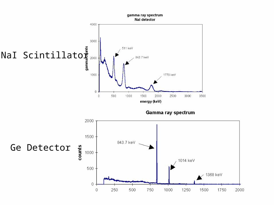
NaI Scintillator
Ge Detector

Ideal Detector for Detection of Radiation
Radiation Ideal Detector Thin Semiconductor Detectors
Proportional Counters Organic Scintillators
Geiger CountersProportional Counters
Inorganic ScintillatorsThick Semiconductor Detectors
neutrons Plastic ScintillatorsProportional Counters (He, BF3)
Lithium Glass Scintillators
Excellent table on Page 61 shows numerous different technologies used in safeguards

Counting Statistics
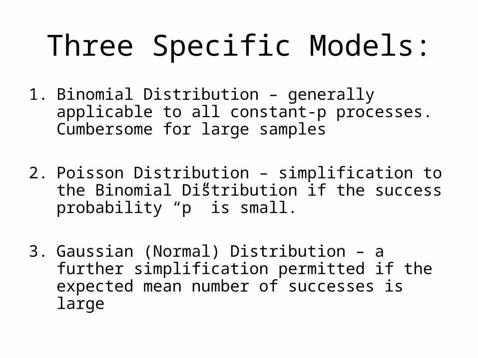
Three Specific Models:
1. Binomial Distribution – generally applicable to all constant-p processes. Cumbersome for large samples
2. Poisson Distribution – simplification to the Binomial Distribution if the success probability “p” is small.
3. Gaussian (Normal) Distribution – a further simplification permitted if the expected mean number of successes is large

The Binomial Distribution
n = number of trialsp = probability of success for each trial
We can then predict the probability of counting exactly“x” successes:
xnx p1p!x!xn
!nxP
P(x) is the predicted “Probability Distribution Function”
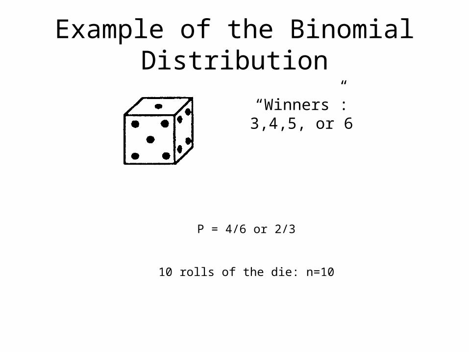
Example of the Binomial Distribution
“Winners”:3,4,5, or 6
P = 4/6 or 2/3
10 rolls of the die: n=10

Results of the Binomial Distribution
p = 2/3
n =10
3
26
npx

Some Properties of the Binomial Distribution
n
0x
1xPIt is normalized:
Mean (average) value
npx
xPxxn
0x

Standard Deviation
xPxx2n
0x
2
iancevar
“Predicted variance”
“Standard Deviation”
is a “typical” value for xx
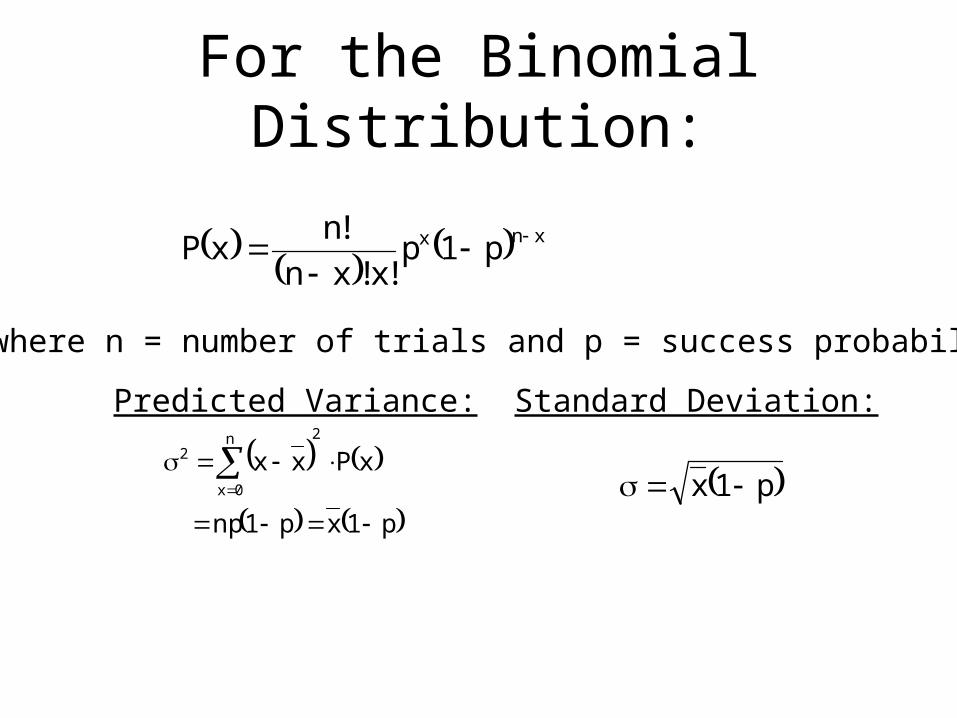
For the Binomial Distribution:
xnx p1p!x!xn
!nxP
p1xp1np
xPxx2n
0x
2
where n = number of trials and p = success probability
p1x
Predicted Variance: Standard Deviation:

For our Previous Example
326npx
22.23
1
3
20p1x2
p = 2/3 n = 10
49.122.22
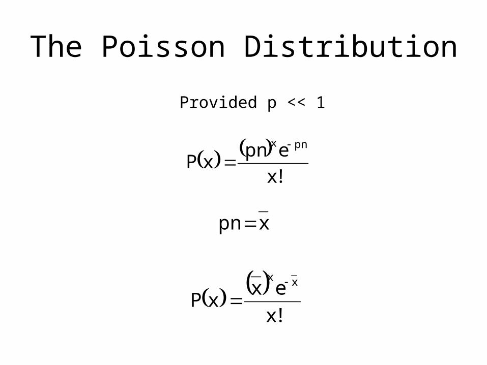
The Poisson Distribution
!x
epnxP
pnx
xpn
Provided p << 1
!x
exxP
xx
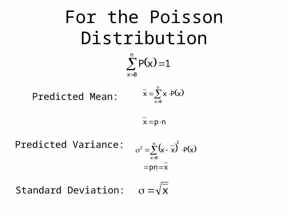
For the Poisson Distribution
n
0x
1xP
npx
xPxxn
0x
xpn
xPxx2n
0x
2
x
Predicted Mean:
Predicted Variance:
Standard Deviation:

Example of the Application of Poisson Statistics
!x
exxP
365
1p
xx
74.2pnx
“Is your birthday today?”
152.0
234
e74.24P
74.24
Example: what is the probability that 4 people out of 1000have a birthday today?

Discrete Poisson Distribution
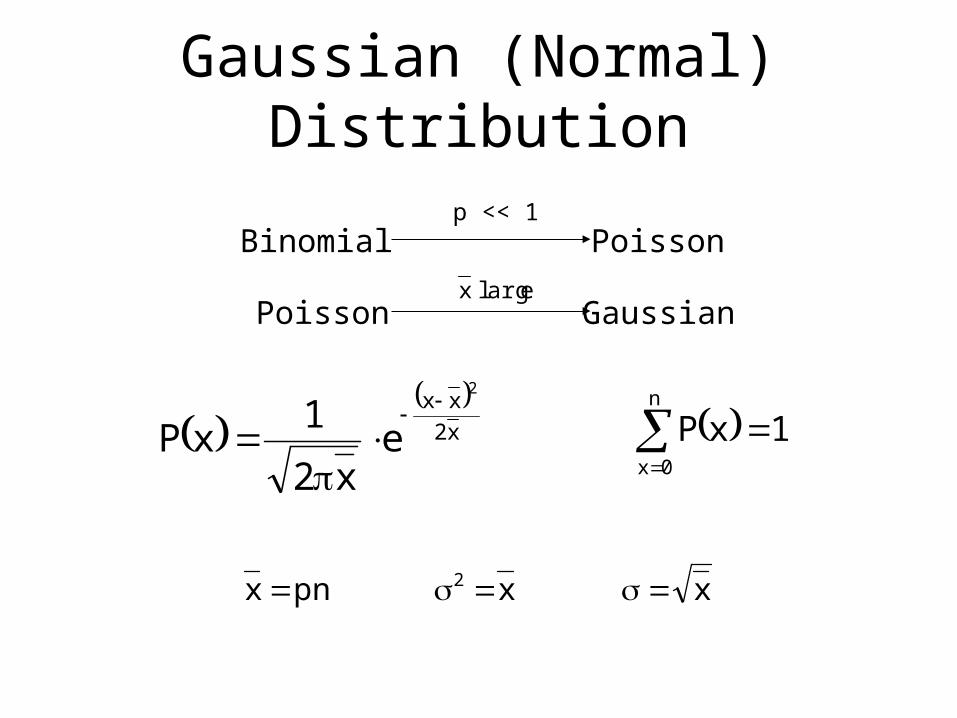
Gaussian (Normal) Distribution
earglx
x2
xx2
ex2
1xP
n
0x
1xP
Binomial
Poisson
Poisson
Gaussian
p << 1
xxpnx 2
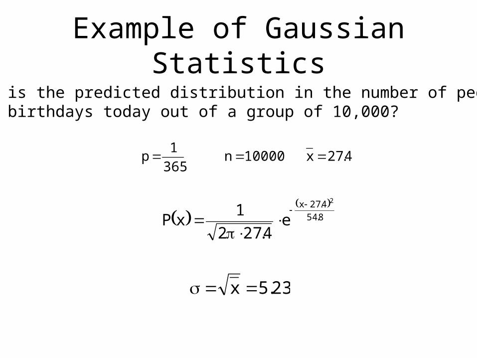
Example of Gaussian Statistics
4.27x10000n365
1p
8.54
4.27x 2
e4.272
1xP
What is the predicted distribution in the number of peoplewith birthdays today out of a group of 10,000?
23.5x
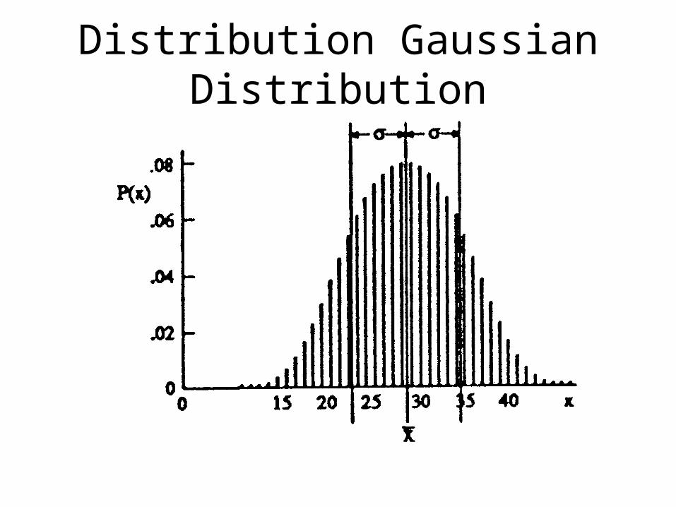
Distribution Gaussian Distribution

The Universal Gaussian Curve
to f(to)
0 0
0.674 0.500
1.00 0.683
1.64 0.900
1.96 0.950
2.58 0.990
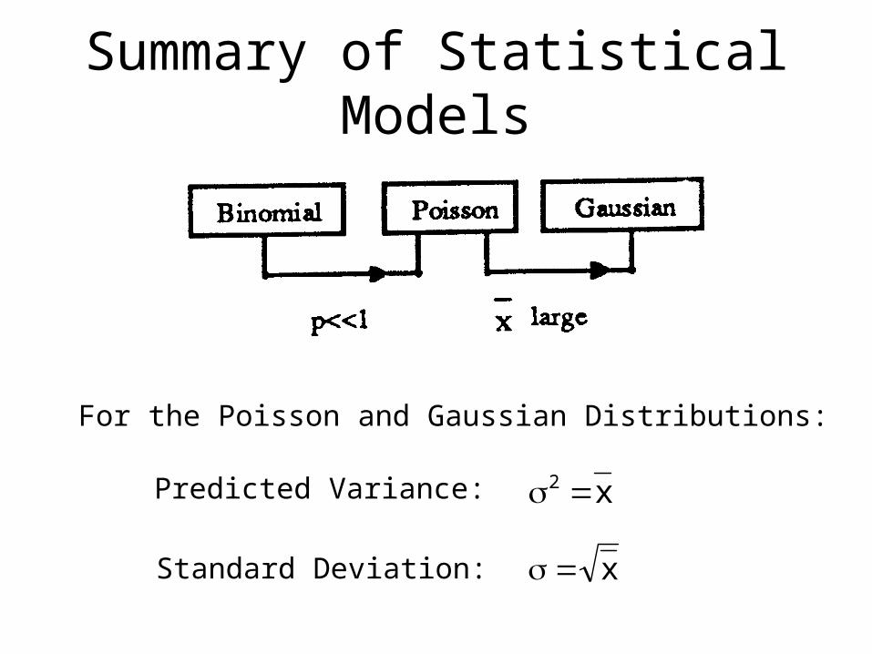
Summary of Statistical Models
x2
For the Poisson and Gaussian Distributions:
Predicted Variance:
Standard Deviation: x

CAUTION!!
eventsradiation
ofnumbercountedarepresents
xifonlyxapplymayWe
Does not apply directly to:
1. Counting Rates
2. Sums or Differences of counts
3. Averages of independent counts
4. Any Derived Quantity

The “Error Propagation Formula”Given: directly measured counts(or other independent variables)
for which the associated standarddeviations are known to be
Derive: the standard deviation of anycalculated quantity
x, y, z, …
x, y, z, …
u(x, y, z, …)
2y
2
2x
22u y
u
x
u
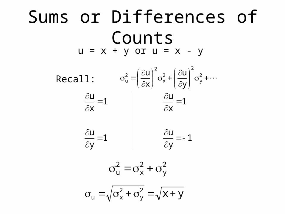
Sums or Differences of Counts
2y
2
2x
22u y
u
x
u
1y
u1
y
u
1x
u1
x
u
2y
2x
2u
u = x + y or u = x - y
Recall:
yx2y
2xu
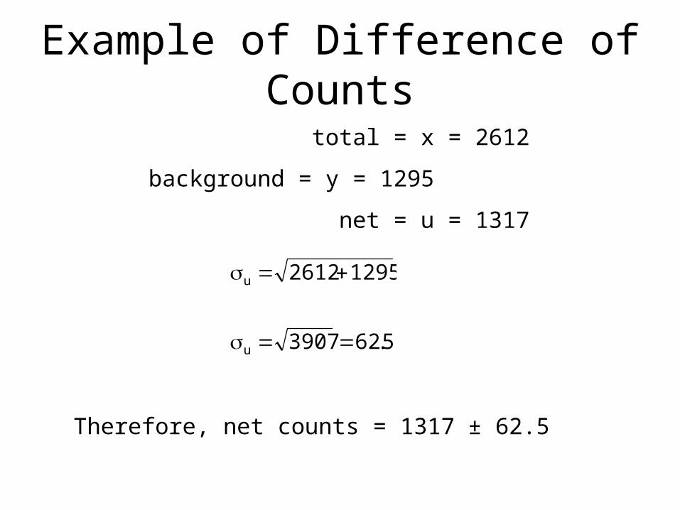
Example of Difference of Counts
total = x = 2612
background = y = 1295
net = u = 1317
5.623907
12952612
u
u
Therefore, net counts = 1317 ± 62.5
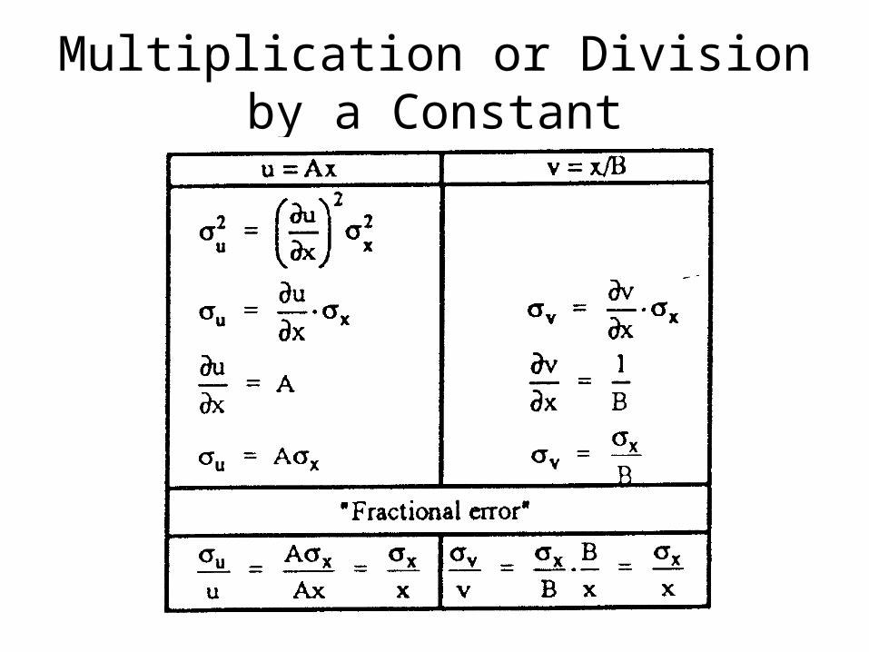
Multiplication or Division by a Constant

Example of Division by a Constant
t
xr
s/89.37s300
11367r
Calculation of a counting rate
x = 11,367 counts t = 300 s
s/36.0s300
11367
tx
r
rate r = 37.89 ± 0.36 s-1

Multiplication or Division of Counts
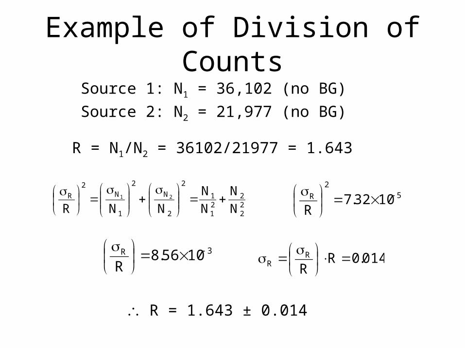
Example of Division of Counts
22
221
1
2
2
N
2
1
N2
R
N
N
N
N
NNR21
5
2
R 1032.7R
3R 1056.8R
Source 1: N1 = 36,102 (no BG)
Source 2: N2 = 21,977 (no BG)
R = N1/N2 = 36102/21977 = 1.643
014.0RR
RR
R = 1.643 ± 0.014

Average Value of Independent Counts
N212x
2x
2x xxx
N21
Nx
Sum: = x1 + x2 + x3 + … + xN
Average:
N
x
N
xN
NNx
Single measurement:
“Improvement Factor”:N
1
N
1
xx
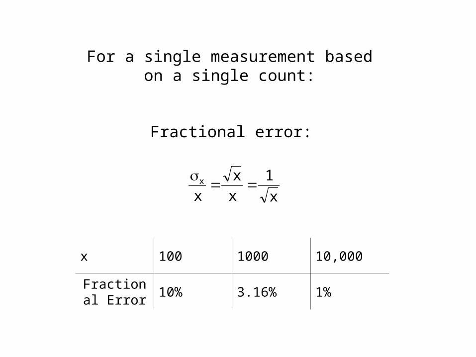
For a single measurement basedon a single count:
Fractional error:
x
1
x
x
xx
x 100 1000 10,000
Fractional Error
10% 3.16% 1%

Limits of Detection
• In many cases within non-proliferation, you are required to measure sources that have a small signal with respect to background sources of radiation
• Thus, we need to assess the minimum detectable amount of a source that can be reliably measured.
• Let’s look at an example of testing the limits of detection
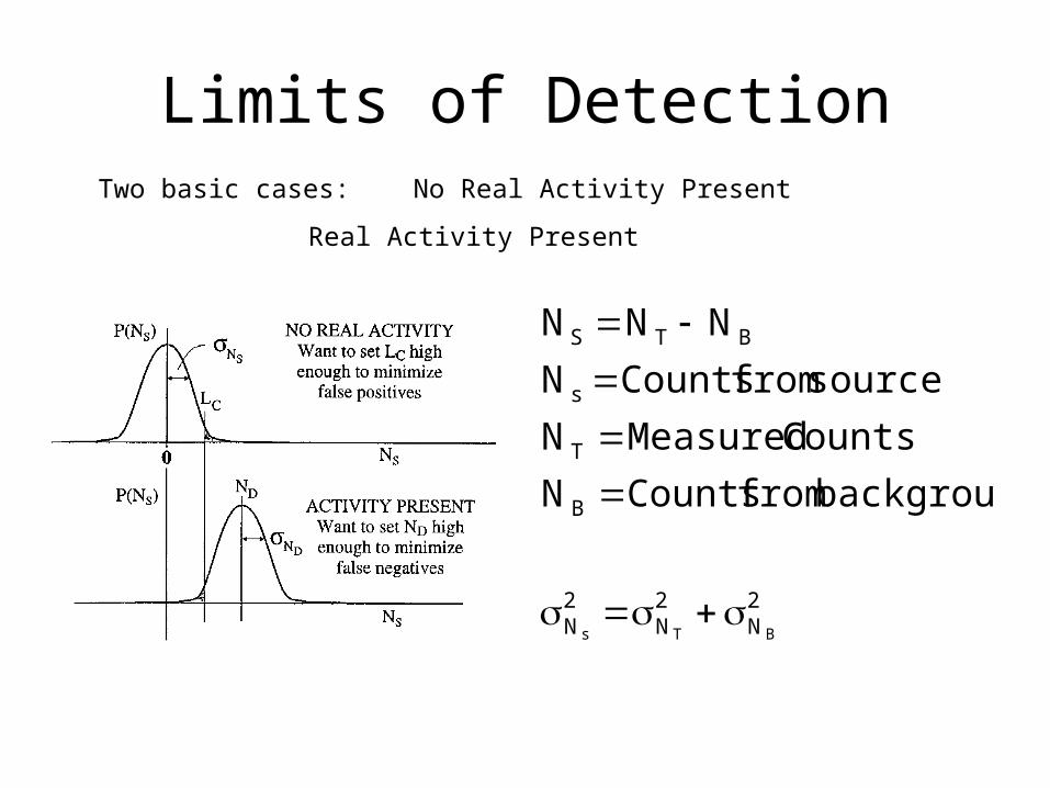
Limits of DetectionTwo basic cases: No Real Activity Present
Real Activity Present
2N
2N
2N
B
T
s
BTS
BTs
backgroundfromCountsN
CountsMeasuredN
sourcefromCountsN
NNN
Limits of Detection – No Source
statisticscountingfromnsfluctuatioonlyifN22
2
BNN
2N
2N
2N
2N
2N
2N
2N
Bs
Bs
BT
BTs
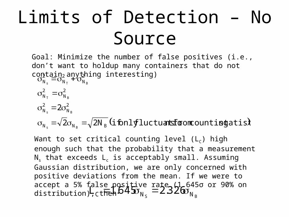
Goal: Minimize the number of false positives (i.e., don’t want to holdup many containers that do not contain anything interesting)
Want to set critical counting level (LC) high enough such that the probability that a measurement Ns that exceeds Lc is acceptably small. Assuming Gaussian distribution, we are only concerned with positive deviations from the mean. If we were to accept a 5% false positive rate (1.645σ or 90% on distribution), then
BS NNC 326.2645.1L

Limits of Detection – Source Present
Goal: Minimize the number of false negatives (i.e., don’t want to let many containers that contain radioactive materials get through). Let ND be the minimum net value of NS that meets this criterion. We can then determine our lower critical set point. Let’s assume an acceptable 5% false negative rate.
BD
BCD
NN
BD
NCD
N653.4N
N326.2LN
2
ionapproximattheusecanwe,NN,But
645.1LN
BD
D
Assumes the width of the distribution of the source + background is approximately the same as that of the background only. In reality, these widths are not the same.
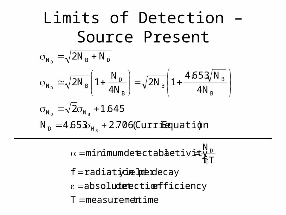
Limits of Detection – Source Present
)EquationCurrie(706.2653.4N
645.12
N4
N653.41N2
N4
N1N2
NN2
B
BD
D
D
ND
NN
B
BB
B
DBN
DBN
timetmeasuremenT
efficiencyectiondetabsolute
decayperyieldradiationfTf
Nactivityectabledetimummin D

Two Interpretations of Limits of Detectability
• LC = lower limit that is set to ensure a 5% false-positive rate
• ND = minimum number of counts needed from a source to ensure a false-negative rate no larger than 5%, when the system is operated with a critical level (or trigger point) LC that ensures a false positive rate no greater than 5%
Neutron DetectionNeutron Coincidence Counting
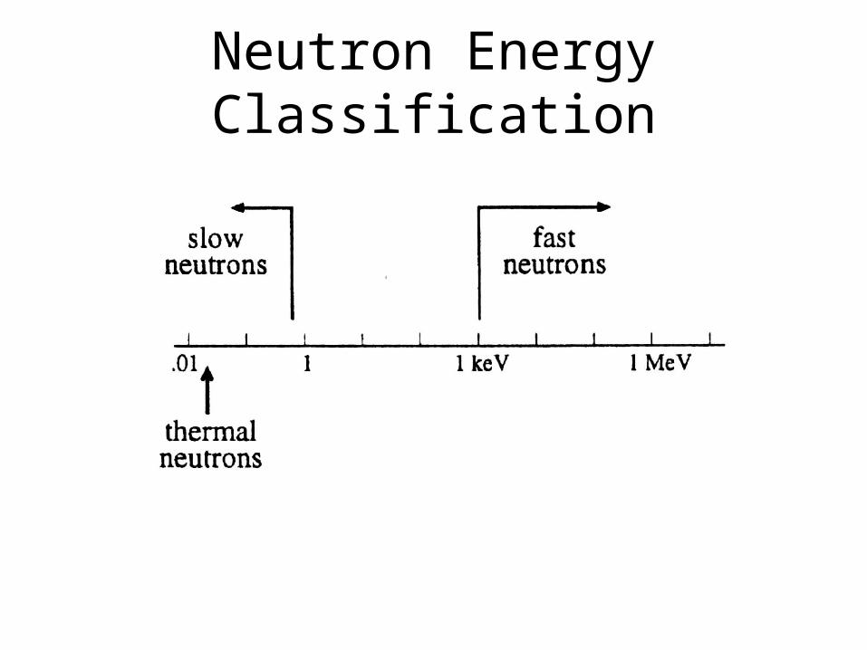
Neutron Energy Classification
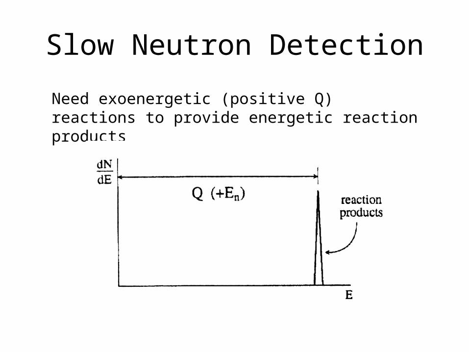
Slow Neutron Detection
Need exoenergetic (positive Q) reactions to provide energetic reaction products

Useful Reactions in Slow Neutron Detection
10B (n, ) 7Li
6Li (n, ) 3H
3He (n, p) 3H
(n, fission)

The 10B(n,) Reaction
310.2Li
792.2LinB
MeVQ
*7
710
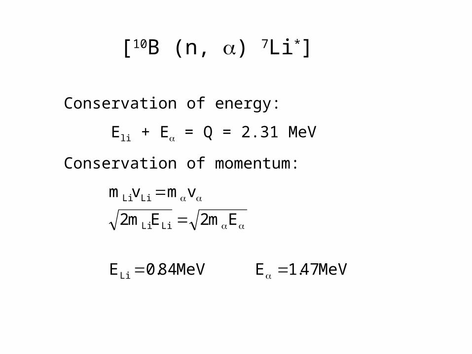
[10B (n, ) 7Li*]
Conservation of energy:
Eli + E = Q = 2.31 MeV
Conservation of momentum:
MeV47.1EMeV84.0E
Em2Em2
vmvm
Li
LiLi
LiLi
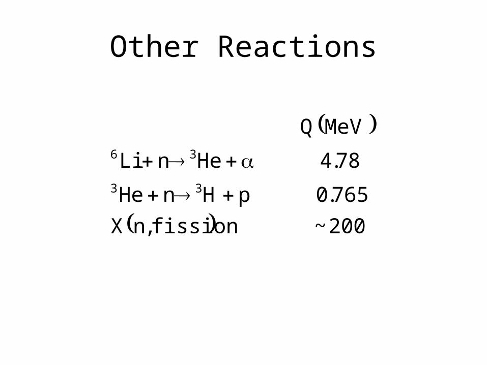
Other Reactions
200~fission,nX
765.0pHnHe
78.4HenLi
MeVQ
33
36
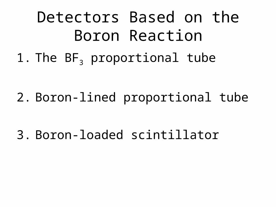
Detectors Based on the Boron Reaction
1. The BF3 proportional tube
2. Boron-lined proportional tube
3. Boron-loaded scintillator
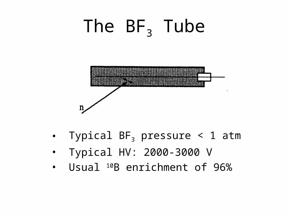
The BF3 Tube
• Typical BF3 pressure < 1 atm
• Typical HV: 2000-3000 V• Usual 10B enrichment of 96%

BF3 – Pulse Height Spectrum

Boron-Lined Proportional Tube
• Conventional proportional gas• Detection efficiency limited by boron thickness

Boron-Lined Proportional Tube – Pulse Height Spectrum

Fast Neutron Detection and Spectroscopy
• Counters based on neutron moderation
• Detectors based on fast neutron-based reactions
• Detectors utilizing fast neutron scattering

Moderated Neutron Detectors

Moderating Sphere
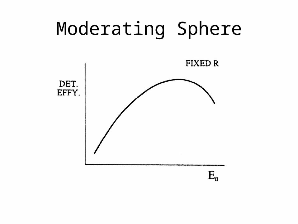
Moderating Sphere
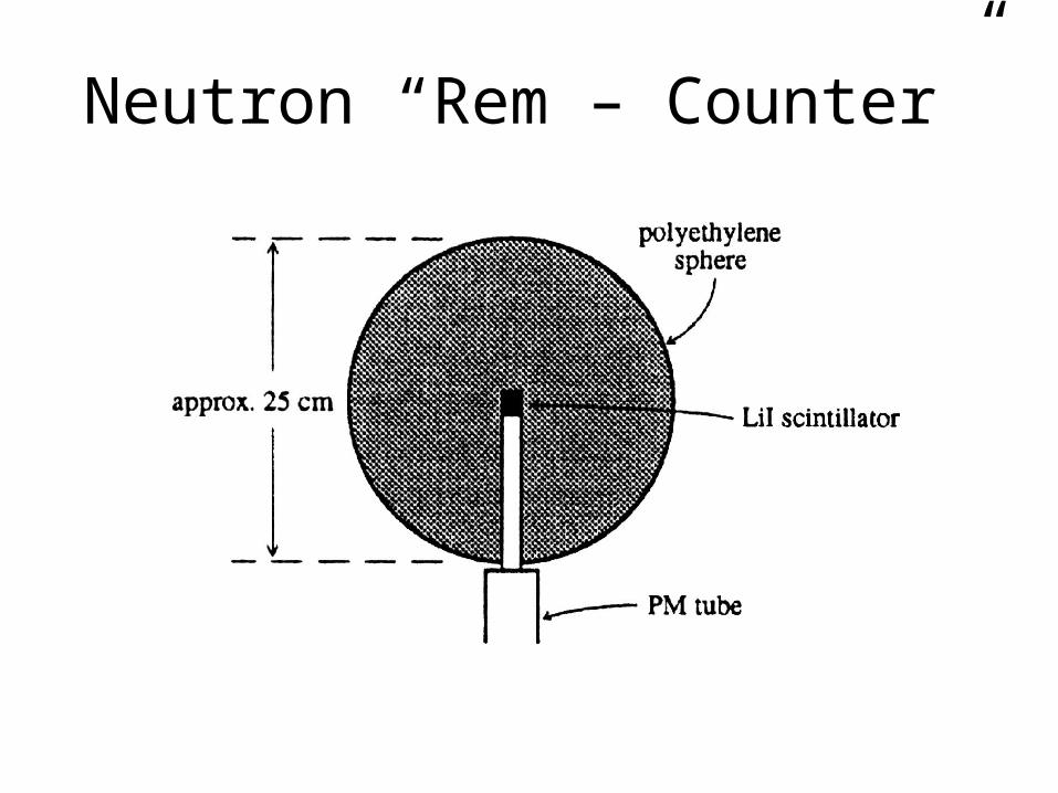
Neutron “Rem – Counter”
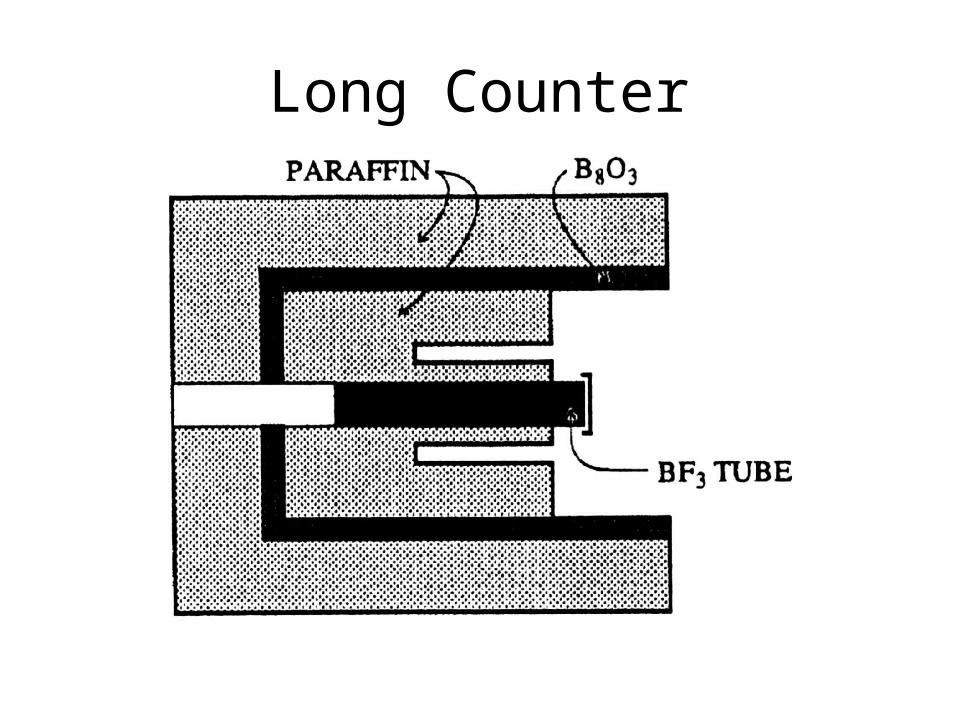
Long Counter

Long Counter Sensitivity
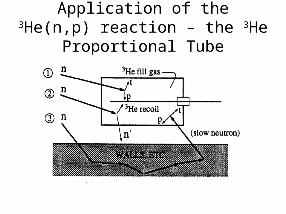
Application of the 3He(n,p) reaction – the 3He Proportional Tube
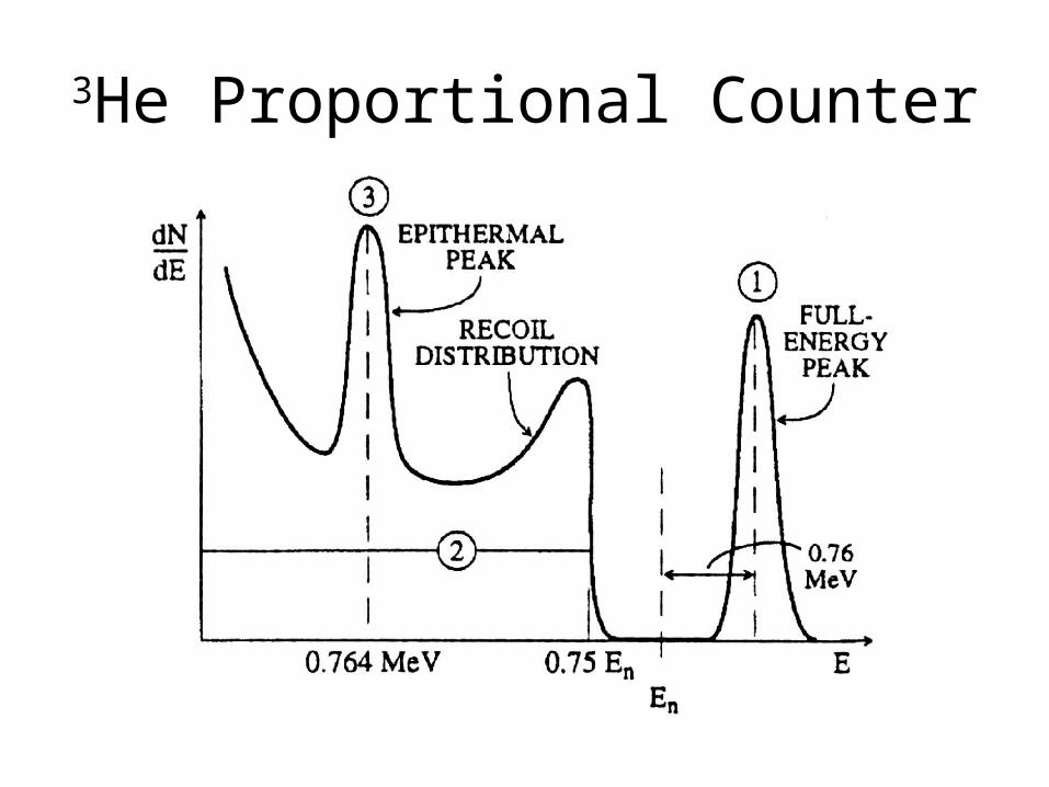
3He Proportional Counter

Detectors that Utilize Fast Neutron Scattering
1. Proton recoil scintillatorHigh (10 – 50%) detection efficiency, complex response
function, gamma rejection by pulse shape discrimination2. Gas recoil proportional tube
Low (.01 - .1%) detection efficiency, can be simpler response function, gamma rejection by amplitude
3. Proton recoil telescopeVery low (~ .001%) detection efficiency, usable only in beam
geometry, simple peak response function4. Capture-gated spectrometer
Modest (few %) detection efficiency, simple peak response function

Proton Recoil Scintillators
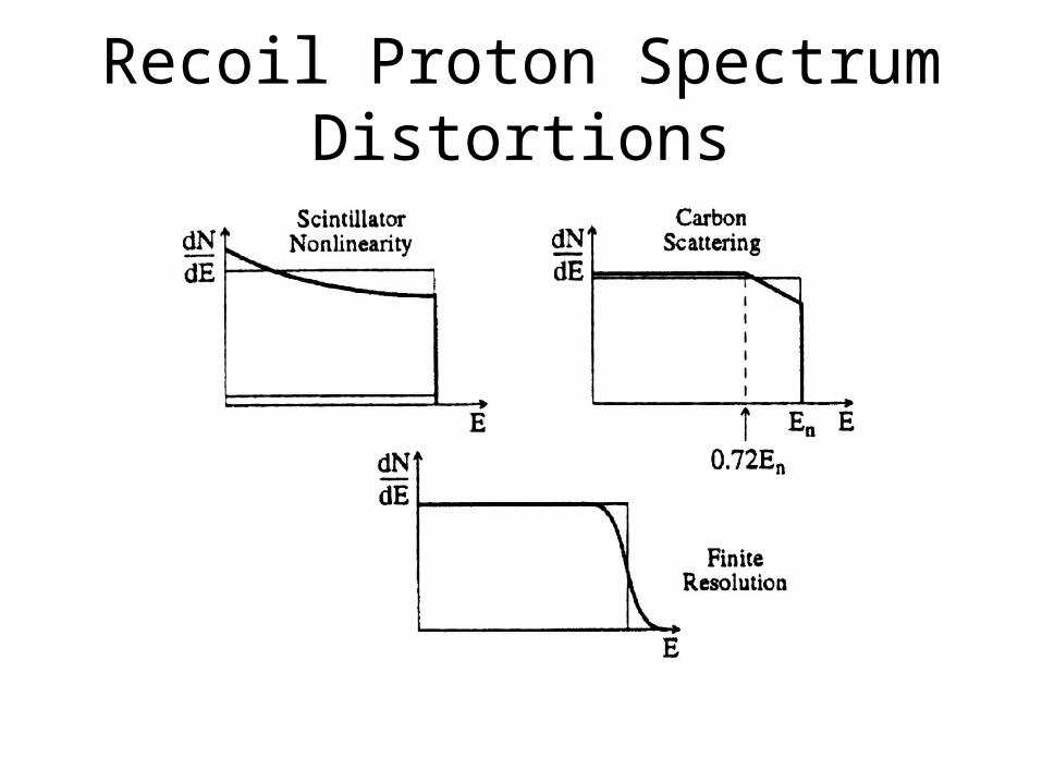
Recoil Proton Spectrum Distortions

Recoil Proton Detector Efficiency
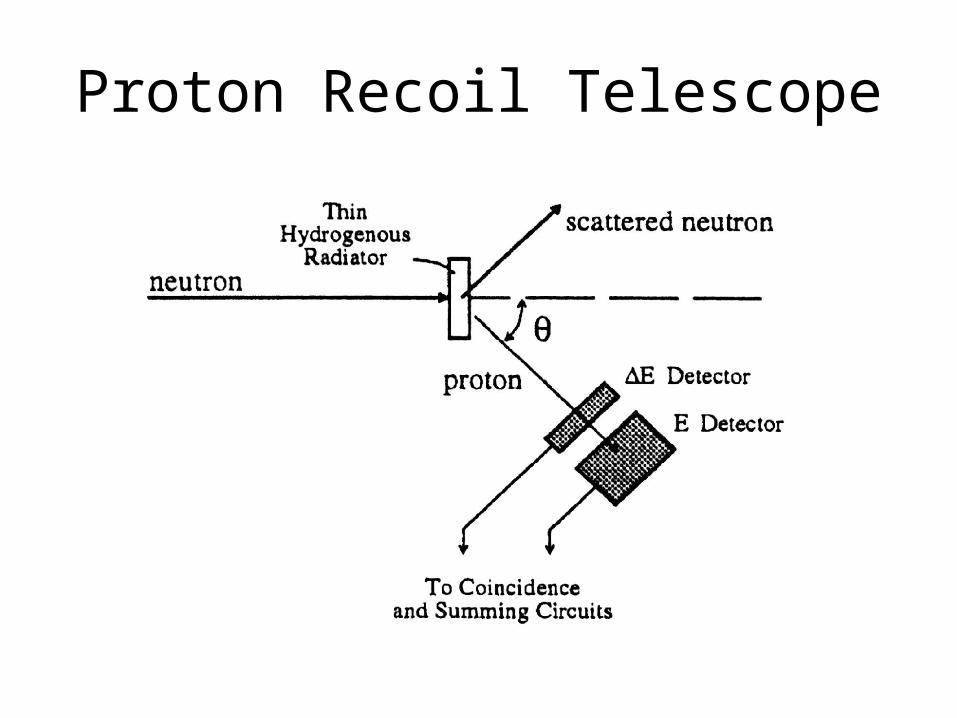
Proton Recoil Telescope
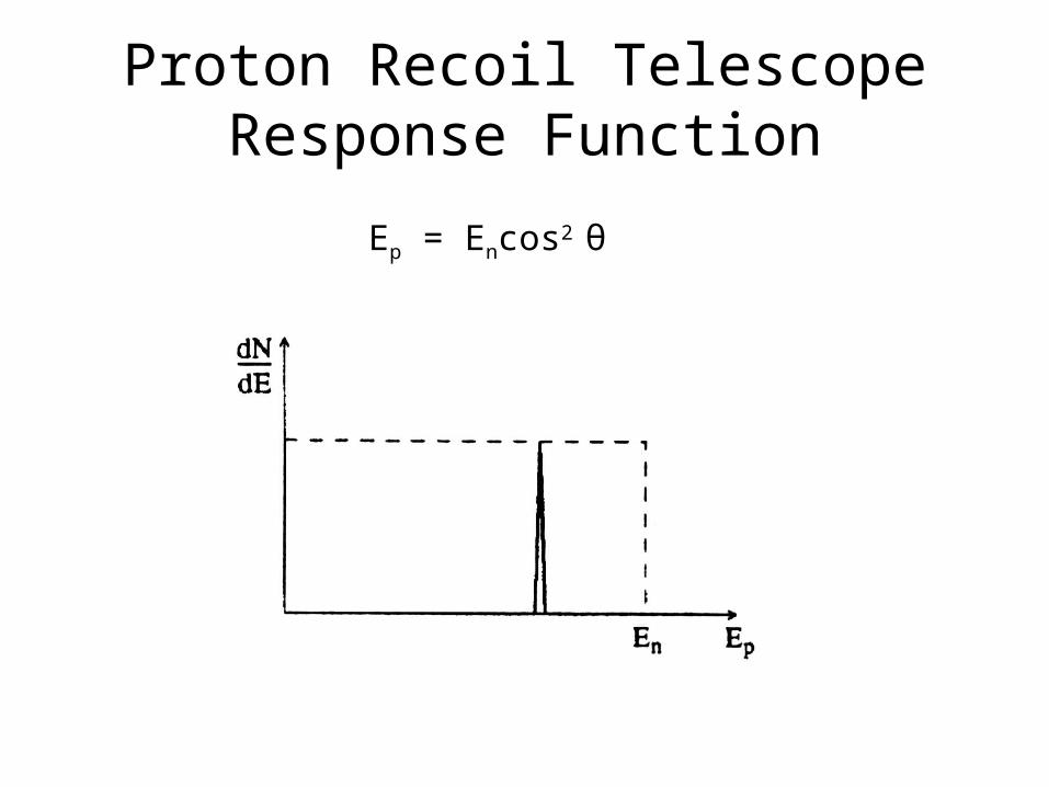
Proton Recoil Telescope Response Function
Ep = Encos2 θ
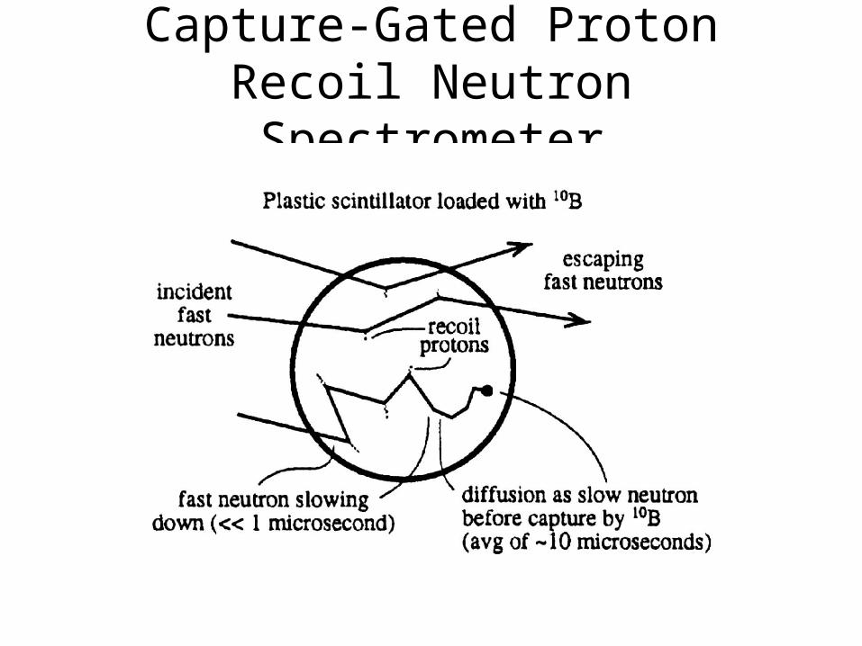
Capture-Gated Proton Recoil Neutron Spectrometer
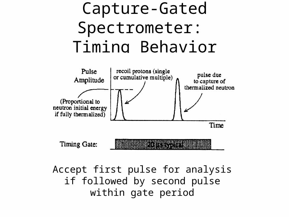
Capture-Gated Spectrometer: Timing Behavior
Accept first pulse for analysis if followed by second pulse within gate period
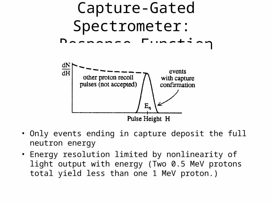
Capture-Gated Spectrometer: Response Function
• Only events ending in capture deposit the full neutron energy
• Energy resolution limited by nonlinearity of light output with energy (Two 0.5 MeV protons total yield less than one 1 MeV proton.)

Neutron Coincidence Counting
• Technique involving the simultaneous measurement of neutrons emitted from a fission source (in “coincidence” with each neutron)
• Used to determine mass of plutonium in unknown samples– Most widely used non-destructive analysis technique for Pu
assay, and can be applied to a variety of sample types (e.g., solids, pellets, powders, etc.)
– Requires knowledge of isotopic ratios, which can be determined by other techniques
– Also used in U assay
Neutron Distribution from Pu Fission

Neutron Coincidence Counting
• Makes use of the fact that plutonium isotopes with even mass number (238, 240, 242) have a high neutron emission rate from spontaneous fission– Spontaneous fission neutrons are emitted at the
same time (time correlated), unlike other neutrons (,n), which are randomly distributed in time
– Count rate of time correlated neutrons is then a complex function of Pu mass

Fission Emission Rates for Pu isotopes
Isotope Spontaneous Neutron Emission Rate
(neutrons/sec-g)
Pu-238 2.59 x 10³
Pu-239 2.18 x 10⁻²
Pu-240 1.02 x 10³
Pu-241 5 x 10⁻²
Pu-242 1.72 x 10³
In reactor fuel, Pu-240 signal dominates over Pu-238 and Pu-242 due to abundance

Neutron Coincidence Counting
• In neutron coincidence counting, the primary quantity determined is the effective amount of Pu-240, which represents a weighted sum of the three even numbered isotopes
• Coefficients for contributions from Pu-238 and Pu-242 are determined by other means, such as knowledge of burnup of reactor fuel. Without additional information, calculation will have errors but will give a good estimate of Pu mass due to relative abundance of the three isotopes. Generally, a ≈2.52, c ≈ 1.68
242240238240 mcmmameff

Neutron Coincidence Counting
• In order to determine the total amount of Pu, mPu, the isotopic mass fractions (R) must be known. These can be easily determined through mass-spectroscopy or gamma-ray spectroscopy, and is then used to calculate the quantity
eff240
240Pu
242240238eff240
Pu
mm
cRRaRPu
eff

NCC Technique
• Utilize He-3 detectors, which can moderate and detect spontaneous fission neutrons
• He-3 detectors usually embedded in neutron moderating material to further slow down neutrons– Increases detection efficiency
• Most common measurement is the simple (2-neutron) coincidence rate, referred to as doubles– If other materials present in the material contribute to neutron signal,
or impact neutron multiplication, other effects may become significant, producing errors
– Generally carried out on relatively pure or well characterized materials, such as Pu-oxides, MOX fuel pins and assemblies

NCC Sources of Uncertainty
• Counting statistics (random)– Can be a significant issue since efficiency can be
low
• Calibration parameters and uncertainties associated with reference materials (systematic)
• Correction for multiplication effects, detector dead time, other neutron emission (systematic)
• Nuclear data
NCC Parameters to Consider
1. Spontaneous fission rate
2. Induced fission
3. (,n) reaction rate
4. Energy spectrum of (,n) neutrons
5. Spatial variation of multiplication
6. Spatial variation of detection efficiency
7. Energy spectrum effects on efficiency
8. Neutron capture in the sample
9. Neutron die-away time in the detector
Clearly, there can be more unknowns than can be determined in conventional NCC

NCC Parameters
• We want to determine 1,2,3• 4 and 5 can be determined with proper use of
modeling and simulation• 6 and 7 can be determined through proper
calibration• 8 and 9 are usually unknown, but in general, are
of minor consequence• Traditional NCC can end up indeterminate –
only 2 equations, but three unknowns

Neutron Multiplicity Measurements
• In neutron multiplicity counting (NMC), one utilizes triple coincidence rates (in addition to single and double counting rates) to provide a third measurement such that all parameters can be determined
• Thus, we are solving three equations with three unknowns – solution is self contained and complete
• One significant advantage of NMC is that there is no need for careful calibration with Pu standards– Also, can measure samples where there may be significant
uncertainties in composition
Design of NMC
• Maximize detection efficiency
• Minimize signal processing time
• Minimize detector die-away time to decrease accidental coincidences
• Minimize geometry effects to efficiency
• Minimize spectral effects on efficiency
Advantages of NMC
• Greater accuracy in Pu mass determination• Self-multiplication and (,n) rates are directly
determined• Calibration does not necessarily require
representative standards• Measurement time on the order of a few thousand
seconds, shorter than the 10,000s typical of NCC• Higher efficiency NMC systems can provide even
shorter measurement times with improved accuracy

Disadvantages of NMC
• Cost
• More floor space required
• Some other techniques can provide shorter measurement times
• Some biases can remain if there is a high degree of uncertainty in measured samples
• Running out of He-3

Examples
• In-Plant NMC measurement system

Examples
• 30-gallon drum measurement system

Examples
• High efficiency neutron counter