
Radiated Spurious Emission Testing - · PDF file · 2012-03-03Radiated Spurious...
42
Transcript of Radiated Spurious Emission Testing - · PDF file · 2012-03-03Radiated Spurious...

What is RSE?
RSE = radiated spurious emission
Radiated chamber
Emission EMI
Spurious intentional radiator
2

Spurious
Spurious, all emissions but the fundamental (carrier)
Spurious can be harmonics, oscillations, mixing terms
3
2.4
GHz
4.8
GHz
7.2
GHz
9.6
GHz
12.0
GHz
14.4
GHz
16.8
GHz
19.2
GHz
21.6
GHz
24.0
GHz
Satellite TV
802.11a
Ultra Wide Band
WiMAX
80
2.1
1 b
/g
Spurious

Spurious Domain
4

Receiver vs. Spectrum analyzer Spurious Emission measurements differ from EMI measurements mainly in that BW’s matching the useful signal have to be set on the receiver instead of the typical EMC bandwidths (e.g. 200 Hz, 9 kHz, 120 kHz).
Also EMC BW’s are referred to the 6 dB points of the IF filters, whereas the BW’s for spurious emission measurements are referred to the 3 dB points.
In spurious emission measurements, the peak detector takes the place of the QP detector.
All these differences make it necessary that for spurious emission measurements a spectrum analyzer or test receiver with spectrum analyzer functionality to be used rather than a pure EMC test receiver
5

Typical RSE Standards
FCC 15C/22/24/ (90) Per 2.2.12 and 2.2.17 of TIA-603-C/D
3GPP standards define RSE for cellular technologies, such as 3GPP.51.010 for GSM (same std as EN 400 367-1)
http://pda.etsi.org/pda/home.asp?wkr=RTS/TSGG-0351010-1v940
ETSI EN 300 328 defines RSE for 2.4 GHz ISM band using spread spectrum modulation, up to 24 GHz ETSI EN 300 440 even defines RSE for equipments used to 40GHz, spurious measured to 100GHz Limit lines are given in dBm, not dBuV
This implies EIRP measurement EIRP not function of test distance So, substitution calibration is required
6

Semi Anechoic Chamber
7
3m Test Distance
0.8m high
1 to 4 m scan high

FCC Chamber
8
FCC does not deviate from general ANSI C63.4 spec when measuring
the RSE, but simply reinforces the use of “typical” 3-meter EMC
chamber.

Noise Floor in FCC 3 meter chamber
9
3m distance
Short cable
Receive antenna 10dB horn
with built-in preamp

ETSI Chamber
10
The above mentioned standards (ETSI 300-328, ETSI 300-440)
clearly define the Reflectivity of absorber and chamber size, not
chamber performance.

ETSI Chamber
11

FCC
Intentional Emitters:
f < 10 GHz: to the tenth harmonic of the highest
fundamental frequency or to 40 GHz, whichever is lower.
In some cases the emissions from an intentional radiator must be
measured to beyond the tenth harmonic of the highest fundamental
frequency designed to be emitted by the intentional radiator
because of the incorporation of a digital device.
FCC Rules Part 22 and 24 requirement for
radiated spurious emissions is as follows:
The ERP limit is –13dBm [derived from 43 +10log(P)]
12

FCC RBW/Limits
13

FCC Spurious Testing, Handset Example
1. Connect the equipment with the EUT’s antenna in a horizontal orientation. If antenna element can be loaded with 50 ohm dummy load please do so or else take care not to overload the receiver/spectrum analyzer.
2. Adjust the settings of the Radio Communication Tester to set the EUT to its maximum power at the required channel. NOTE, Requires communication antenna to maintain the link!
3. Set the spectrum analyzer to measure peak hold.
4. Place the measurement antenna in a horizontal orientation. Raise the measurement from 1m up to 4 meters in steps and rotate the EUT 360 degrees at each height to maximize all emissions. Measure and record all spurious emissions (LVL) up to the tenth harmonic of the carrier frequency.
5. Replace the EUT with a horizontally polarized half wave dipole or known gain antenna. The center of the antenna should be at the same location as the center of the EUT’s antenna.
Step is typically performed prior to testing and LOSS is recorded by test software
14

FCC Spurious Testing, Handset Example 6. Connect the antenna to a signal generator with known output power and
record the path loss in dB (LOSS). LOSS = Generator Output Power
(dBm) – Analyzer reading (dBm).
Step is typically performed prior to testing and LOSS is recorded by test software
7. Determine the level of spurious emissions using the following equation:
Spurious (dBm) = LVL (dBm) + LOSS (dB):
8. Repeat steps 4, 5 and 6 with all antennas vertically polarized.
9. Measurements are to be performed with the EUT set to the low, middle
and high channel of each frequency band.
15

FCC 22.917 Emission limitations for cellular equipment
The rules in this section govern the spectral characteristics of emissions in the Cellular Radiotelephone Service.
(a) Out of band emissions. The power of any emission outside of the authorized operating frequency ranges must be attenuated below the transmitting power (P) by a factor of at least 43 + 10 log(P) dB.
(b) Measurement procedure. Compliance with these provisions is based on the use of measurement instrumentation employing a resolution bandwidth of 100 kHz or greater. In the 1 MHz bands immediately outside and adjacent to the frequency block a resolution bandwidth of at least one percent of the emission bandwidth of the fundamental emission of the transmitter may be employed. A narrower resolution bandwidth is permitted in all cases to improve measurement accuracy provided the measured power is integrated over the full required measurement bandwidth (i.e. 100 kHz of 1 percent of emission bandwidth, as specified). The emission bandwidth is defined as the width of the signal between two points, one below the carrier center frequency and one above the carrier center frequency, outside of which all emissions are attenuated at least 26 dB below the transmitter power.
16

FCC 24.238 Emission limitations for Broadband PCS equipment.
The rules in this section govern the spectral characteristics of emissions in the Broadband Personal Communications Service.
(a) Out of band emissions. The power of any emission outside of the authorized operating frequency ranges must be attenuated below the transmitting power (P) by a factor of at least 43 + 10 log(P) dB.
(b) Measurement procedure. Compliance with these provisions is based on the use of measurement instrumentation employing a resolution bandwidth of 1 MHz or greater. However, in the 1 MHz bands immediately outside and adjacent to the frequency block a resolution bandwidth of at least one percent of the emission bandwidth of the fundamental emission of the transmitter may be employed. A narrower resolution bandwidth is permitted in all cases to improve measurement accuracy provided the measured power is integrated over the full required measurement bandwidth (i.e. 100 kHz of 1 percent of emission bandwidth, as specified). The emission bandwidth is defined as the width of the signal between two points, one below the carrier center frequency and one above the carrier center frequency, outside of which all emissions are attenuated at least 26 dB below the transmitter power.
17

Example of FCC Spurious Test
18
Uplink Signal

ETSI Standard Basics
19
EMI measured from 30MHz to 12.75GHz
The receiving device is spectrum analyzer (3dB BW RBW), not EMI receiver (6dB BW RBW).
No defined chamber performance test
Only absorber requirement
And suggested chamber size (10m x 5m x 5m)

ETSI RBW/VBW Settings
20
Here is to given one example.

ETSI Limits
21
Harmonics are mostly limited to -30dBm (in dBd), or -27.85dBm (in dBi) [dBd = dBi – 2.15]

Basic ETSI RSE System Diagram
22
3D positioner for 3D measurement
Notch Filter to remove fundamental carrier
Preamp to increase dynamic range
Notch Filter Preamp

Filters for Wireless
Compliant EMC Solution
For Measurement of the radiation and sensitivity of wireless
devices under different signal protocols and frequency.
Main carrier frequencies used are:
800MHz, 900MHz, 1.2GHz, 2.4GHz ....
When measuring broadband responses these carrier
frequencies need to be included in the measurement path.
Pre Compliant MAPS Solution
Pre compliant solution (above 200/700 MHz only)
Upper frequencies only
23

Filters for EMC and Wireless
24

Filters for Wireless

Filters for Wireless
Filters selected from a number of different manufacturers

Typical Notch Filter
27
Very sharp rejection band - 50dB rejections in 200kHz bandwidth
To notch out the fundament which is strong enough to saturate receiver

Preamp
28
Preamp is essentially LNA (low noise amp) to boost up weak spurious to become detectable
Carefully select preamp to have enough dynamic range
Preamp is connected right after next to the receive antenna, after the notch filter, in good compliant RSE system.

Filters for EMC
EMC Solution for 2.7GHz or 6 GHz to 18 GHz
29
HPF filter used in series with Pre amplifier
Protects preamp from overload.

Filters for EMC
EMC Solution for 2.7GHz or 6GHz to 18 GHz
30
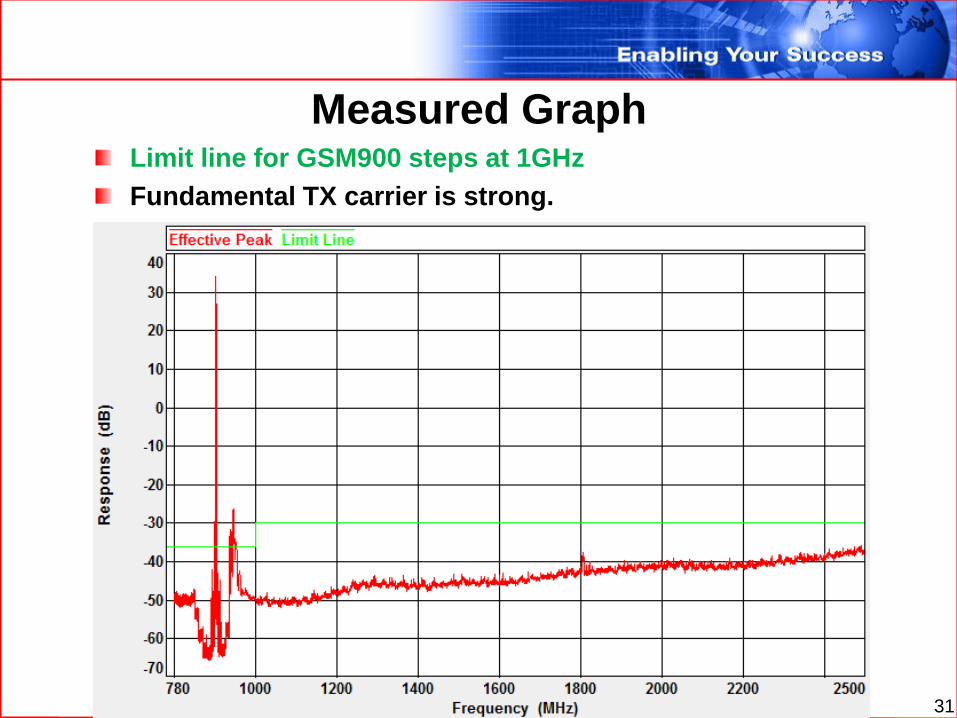
Measured Graph
31
Limit line for GSM900 steps at 1GHz
Fundamental TX carrier is strong.

Exclusion Band
32
The fundament of 902.4MHz is taken out by the
BW of 3.6MHz.

Table
33
Table picks up peaks.

Pre Test Calibration Methodology
The FCC has received several inquires regarding the
acceptance of an adjunct methodology, whereby a signal
generator is used to radiate a signal that is swept over a
pertinent frequency range, and then recorded at a single
point in space at a distance corresponding to the
measurement distance required for compliance testing. A
table of data collected from this site “pre-calibration” is
then to be used to replace specific substitution
procedures as described in Sections 2.2.12 (j) through (l)
and/or 2.2.17 (c) and (d) of the TIA-603-C standard.
34

Pre Test Calibration Methodology
FCC Released a KDB 449343
(https://apps.fcc.gov/oetcf/kdb/forms/FTSSearch
ResultPage.cfm?id=47471&switch=P) recognizing
that there are labs using this method and prior to
it being recognized by any industry standard or
officially by FCC it is not acceptable at this point.
There was a response submitted to try to get this
methodology included as part of the FCC
approved methodologies for this test.
35

Pre Test Calibration Methodology
EMC test labs have technically justified and used
pre-test site calibrations to evaluate the field
strength of radiated emissions in lieu of
individual substitution measurements for each
emission for many years.
36

Pre Test Calibration Methodology
Procedure
Reference Field Strength
The related regulatory compliance limit [e.g. -13 dBm / -20 dBm]
should be used as the reference field strength for the pre-test site
calibration.
However, as long the system sensitivity of the measurement system
is adequate, labs are able to define their own reference field
strength.
Labs should be capable of justifying their decision of reference field
strength.
37

Pre Test Calibration, Procedure Measurement instruments used for path loss calibration do not need to be the same as ultimately used for measuring EUT radiated power
Swept frequency measurement under consideration Network analyzer Speed.
It is very important that antenna locations, measurement antenna and related measurement cables to be the same for both the path loss calibration and EUT measurements.
If any of these elements change, then site calibration shall be verified before continuing with EUT testing
A preamplifier can be utilized for testing even if it was not part of the path loss measurement.
Correction Factor (CF) determined on the exact frequencies of the EUT emission testing or calculated using linear interpolation between site calibration frequencies
38

Pre Test Calibration, Procedure Set up the substitution measurement with the ref. point of the substitution antenna located in the position where the closest periphery of the EUT will be located during EUT measurements.
The height of the substitution antenna should be at approximately the same height as the where center of the transmitter to be tested would be located.
Set the test receiver settings and receive path parameters exactly as they will be used during emissions measurements.
Connect a signal generator to the substitution antenna and set the level according
Pgen = Pref + Cable Loss - Antenna Gain [dBd]
Where Pgen = signal generator setting [dBm]
Pref = Reference Field Strength
Antenna Gain [dBd] = Antenna Gain [dBi] - 2.15
Antenna Gain [dBi] = 10*Log (Num Gain)
Scan antenna 1m to 4m to determine the height of the maximum received level.
39

Pre Test Calibration, Procedure Record the level of the received power [Prec] at the Receiver in dBm for that frequency and polarization.
Perform the leveling of the signal generator power for each frequency with the receive antenna oriented in both the polarizations as described above.
Calculate the system correction factor for each frequency in dB using the following equation:
Correction Factor [CF] = Pref [dBm] – Prec [dBm]
For example:
At 4800 MHz for a frequency / polarization
Prec = -34.8 dBm for a -13 dBm limit
CF = -13 dBm – [-34.8 dBm] = 21.8 dB
Using Pre-Test Site Calibration Correction Factor to Determine EUT Emission Power
EUT emission powers are calculated using the following equation:
Emission Power = EPrec dBm + CF
Where EPrec is the power of the emission measured at the test receiver during EUT measurements as defined in TIA 603C/D section 2.2.12.2 a - 2.2.12.2 g.
This is the level to be compared against the regulatory limit as it is the emission power referenced back to the EUT on the test site.
40

Pre Test Calibration
Concerns
Multitude of Correction Factors for variety of different EUT
sizes, diameter, height and cable orientations.
Needs to be careful that right files are used or use methodology to
reduce the error by performing a series of tests (or volumetric) for
different path loss measurements and do 1/r distance correction to
reduce the chamber associated ripple.
Maybe you can live then with one Correction Factor for the center and
then just reduce the correction factor based on the radius of the EUT.
How sensitive the calibration factor determination is for set-
up.
Do labs start taking short cuts if the set-up is “close enough” for the
calibration factors already existing.
How to audit ?
41

QUESTIONS
6-23-2010 42