Radial Shaft Seal Technical Manual - · PDF fileRadial Shaft Seal Technical Manual ... of the...
68
Service Radial Shaft Seal Technical Manual Freudenberg–NOK Sealing Technologies
-
Upload
nguyenliem -
Category
Documents
-
view
254 -
download
4
Transcript of Radial Shaft Seal Technical Manual - · PDF fileRadial Shaft Seal Technical Manual ... of the...
Service
Radial Shaft Seal Technical Manual
Freudenberg–NOK Sealing Technologies
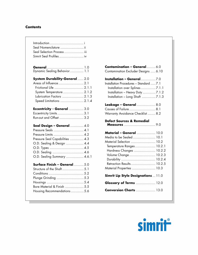
Introduction ................................... iSeal Nomenclature ........................ iiSeal Selection Process .................... iiiSimrit Seal Profiles ......................... iv
General ...................................... 1.0Dynamic Sealing Behavior .............. 1.1
System Durability-General ...... 2.0Areas of Influence .......................... 2.1
Frictional Life .............................. 2.1.1System Temperature ..................... 2.1.2Lubrication Factors ...................... 2.1.3Speed Limitations ........................ 2.1.4
Eccentricity - General ............... 3.0Eccentricity Limits ........................... 3.1Run-out and Offset ......................... 3.2
Seal Design – General .............. 4.0Pressure Seals ............................... 4.1Pressure Limits ............................... 4.2Pressure Seal Capabilities .............. 4.3O.D. Sealing & Design .................. 4.4O.D. Types ................................... 4.5O.D. Sealing ................................ 4.6O.D. Sealing Summary .................. 4.6.1
Surface Finish – General .......... 5.0Structure of the Shaft ...................... 5.1Conditions .................................... 5.2Plunge Grinding ............................ 5.3Housings ...................................... 5.4Bore Material & Finish ................... 5.5Housing Recommendations ............. 5.6
Contamination – General ......... 6.0Contamination Excluder Designs ..... 6.10
Installation – General ............... 7.0Installation Procedures – Standard ..... 7.1 Installation over Splines ............... 7.1.1 Installation – Heavy Duty ............. 7.1.2 Installation – Long Shaft .............. 7.1.3
Leakage – General ................... 8.0Causes of Failure ........................... 8.1Warranty Avoidance Checklist ........ 8.2
Defect Sources & Remedial Measures ................................ 9.0
Material – General ................... 10.0Media to be Sealed ....................... 10.1Material Selection ......................... 10.2 Temperature Ranges..................... 10.2.1 Hardness Changes ...................... 10.2.2 Volume Change........................... 10.2.3 Durability ................................... 10.2.4 Retraction Results ......................... 10.2.5Material Properties ........................ 10.3
Simrit Lip Style Designations ... 11.0
Glossary of Terms .................... 12.0
Conversion Charts .................... 13.0
Contents
Introduction:
The data in this technical catalog is based on experience gainedby Simrit through the Freudenberg & NOK Group Companies.Decades of research have been conducted into both the develop-ment and manufacture of our Simrit Radial Shaft Seals. Neverthe-less, the information in this catalog may be significantly modifiedas a result of factors occurring during practical use of our product,which may be unknown to the company. Therefore,the datacontained herein, can only be considered general, non-binding,approximate values. For this reason we strongly encourage you tocontact your Simrit representative to discuss specific applications.
The data in this catalog may be altered without prior notice.
This publication may only be reproduced with the express consentof Simrit:
Simrit
This publication supercedes and renders all previous Radial Shaft Seal Technical Data invalid.
i
2250 Point Boulevard, Suite 230Elgin, IL 60123Phone: +1 (847) 428-1261Attention: Simrit Global Marketing Communications
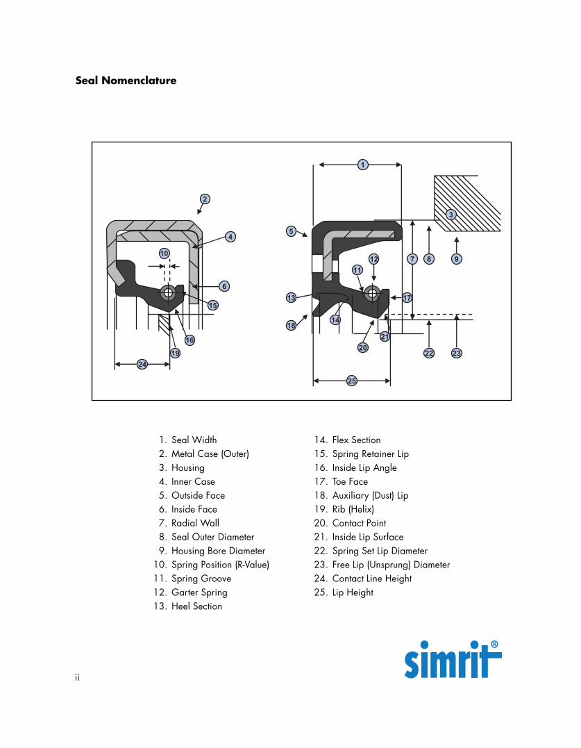
1. Seal Width2. Metal Case (Outer)3. Housing4. Inner Case5. Outside Face6. Inside Face7. Radial Wall8. Seal Outer Diameter9. Housing Bore Diameter
10. Spring Position (R-Value)11. Spring Groove12. Garter Spring13. Heel Section
14. Flex Section15. Spring Retainer Lip16. Inside Lip Angle17. Toe Face18. Auxiliary (Dust) Lip19. Rib (Helix)20. Contact Point21. Inside Lip Surface22. Spring Set Lip Diameter23. Free Lip (Unsprung) Diameter24. Contact Line Height25. Lip Height
Seal Nomenclature
ii
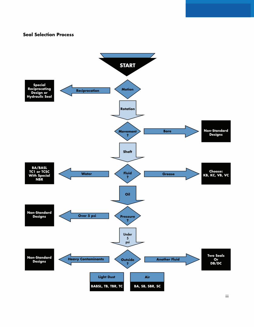
Seal Selection Process
Rotation
Movement?
Shaft
Bore
SpecialReciprocating
Design orHydraulic Seal
Fluid?
Grease
BA/BASLTC1 or TCSCWith Special
NBR
Water
Non-StandardDesigns
Non-StandardDesigns
Two SealsOr
DB/DC
Oil
Over 5 psi
Heavy Contaminants Outside?
Another Fluid
Under5
psi
Motion
START
Reciprocation
Choose:KB, KC, VB, VC
Non-StandardDesigns
Pressure?
iii
BA, SB, SBR, SC
Air
BABSL, TB, TBR, TC
Light Dust
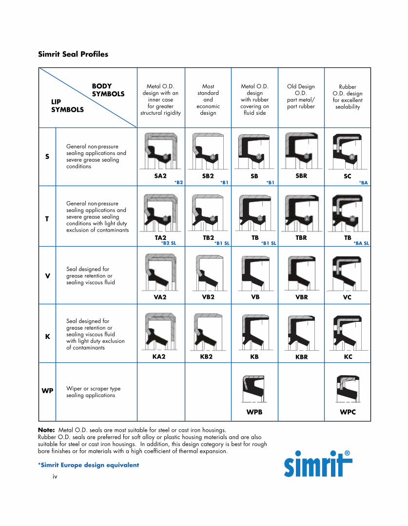
Note: Metal O.D. seals are most suitable for steel or cast iron housings.Rubber O.D. seals are preferred for soft alloy or plastic housing materials and are alsosuitable for steel or cast iron housings. In addition, this design category is best for roughbore finishes or for materials with a high coefficient of thermal expansion.
*Simrit Europe design equivalent
Simrit Seal Profiles
LIPSYMBOLS
BODYSYMBOLS
Metal O.D.design with an
inner casefor greater
structural rigidity
Moststandard
andeconomic
design
Metal O.D.design
with rubbercovering onfluid side
Old DesignO.D.
part metal/part rubber
RubberO.D. designfor excellentsealability
General non-pressuresealing applications andsevere grease sealingconditions
General non-pressuresealing applications andsevere grease sealingconditions with light dutyexclusion of contaminants
Seal designed forgrease retention orsealing viscous fluid
Seal designed forgrease retention orsealing viscous fluidwith light duty exclusionof contaminants
Wiper or scraper typesealing applications
S
T
V
K
WPB WPC
SB *B1
SC *BA
TB2 *B1 SL
TB *B1 SL
VB2 VB
KB KBR KC
SB2 *B1
SBRSA2 *B2
TA2 TBR TB *BA SL
VA2 VBR VC
WP
iv
KA2 KB2
*B2 SL
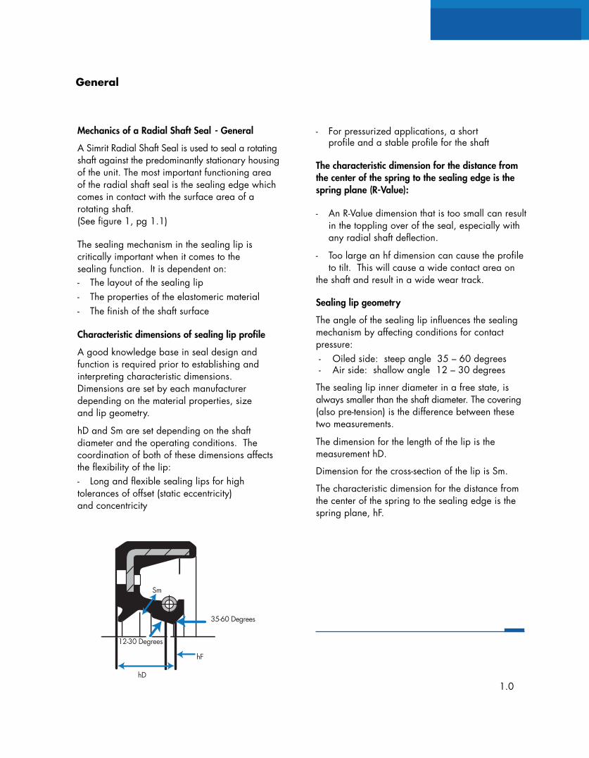
Mechanics of a Radial Shaft Seal - General
A Simrit Radial Shaft Seal is used to seal a rotatingshaft against the predominantly stationary housingof the unit. The most important functioning areaof the radial shaft seal is the sealing edge whichcomes in contact with the surface area of arotating shaft.(See figure 1, pg 1.1)
The sealing mechanism in the sealing lip iscritically important when it comes to thesealing function. It is dependent on:- The layout of the sealing lip- The properties of the elastomeric material- The finish of the shaft surface
Characteristic dimensions of sealing lip profile
A good knowledge base in seal design andfunction is required prior to establishing andinterpreting characteristic dimensions.Dimensions are set by each manufacturerdepending on the material properties, sizeand lip geometry.
hD and Sm are set depending on the shaftdiameter and the operating conditions. Thecoordination of both of these dimensions affectsthe flexibility of the lip:- Long and flexible sealing lips for hightolerances of offset (static eccentricity)and concentricity
- For pressurized applications, a shortprofile and a stable profile for the shaft
The characteristic dimension for the distance fromthe center of the spring to the sealing edge is thespring plane (R-Value):
- An R-Value dimension that is too small can resultin the toppling over of the seal, especially withany radial shaft deflection.
- Too large an hf dimension can cause the profileto tilt. This will cause a wide contact area on
the shaft and result in a wide wear track.
Sealing lip geometry
The angle of the sealing lip influences the sealingmechanism by affecting conditions for contactpressure: - Oiled side: steep angle 35 – 60 degrees - Air side: shallow angle 12 – 30 degrees
The sealing lip inner diameter in a free state, isalways smaller than the shaft diameter. The covering(also pre-tension) is the difference between thesetwo measurements.
The dimension for the length of the lip is themeasurement hD.
Dimension for the cross-section of the lip is Sm.
The characteristic dimension for the distance fromthe center of the spring to the sealing edge is thespring plane, hF.
General
1.0
35-60 Degrees
12-30 Degrees
Sm
hF
hD
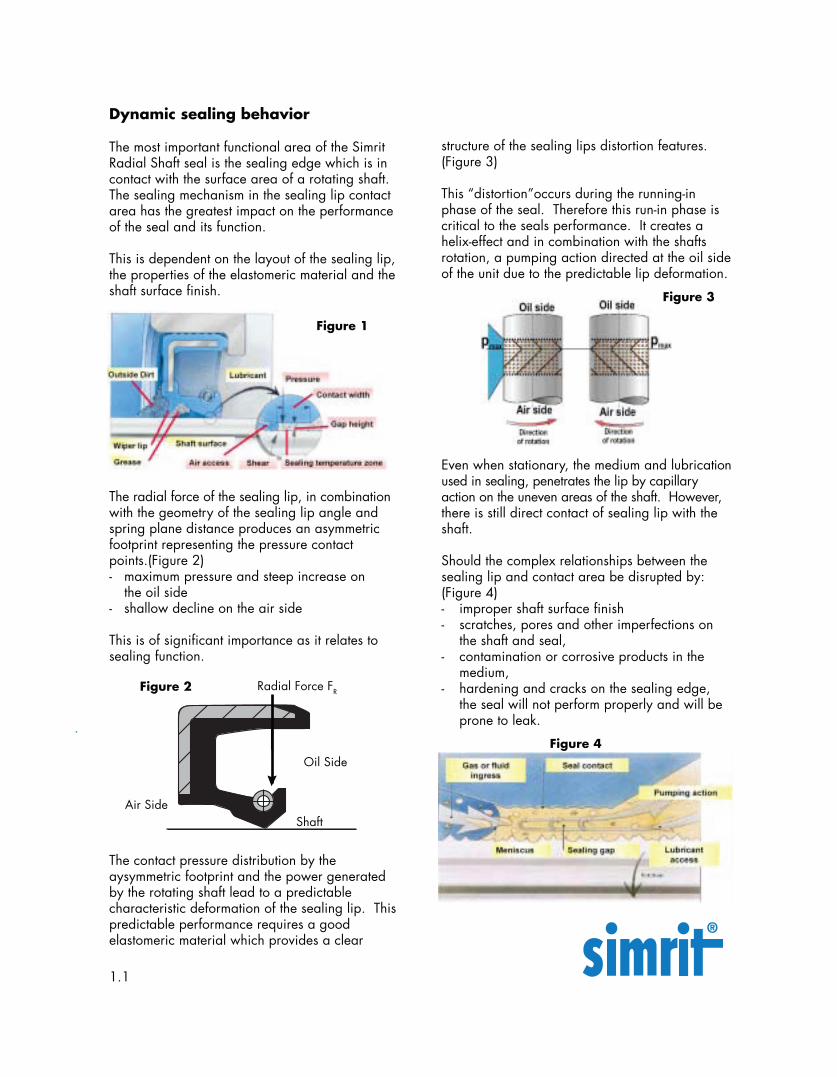
The radial force of the sealing lip, in combinationwith the geometry of the sealing lip angle andspring plane distance produces an asymmetricfootprint representing the pressure contactpoints.(Figure 2)- maximum pressure and steep increase on
the oil side- shallow decline on the air side
This is of significant importance as it relates tosealing function.
Even when stationary, the medium and lubricationused in sealing, penetrates the lip by capillaryaction on the uneven areas of the shaft. However,there is still direct contact of sealing lip with theshaft.
Should the complex relationships between thesealing lip and contact area be disrupted by:(Figure 4)- improper shaft surface finish- scratches, pores and other imperfections on
the shaft and seal,- contamination or corrosive products in the
medium,- hardening and cracks on the sealing edge,
the seal will not perform properly and will beprone to leak.
Dynamic sealing behavior
The most important functional area of the SimritRadial Shaft seal is the sealing edge which is incontact with the surface area of a rotating shaft.The sealing mechanism in the sealing lip contactarea has the greatest impact on the performanceof the seal and its function.
This is dependent on the layout of the sealing lip,the properties of the elastomeric material and theshaft surface finish.
The contact pressure distribution by theaysymmetric footprint and the power generatedby the rotating shaft lead to a predictablecharacteristic deformation of the sealing lip. Thispredictable performance requires a goodelastomeric material which provides a clear
Dynamic Sealing Behavior
Figure 1
structure of the sealing lips distortion features.(Figure 3)
This “distortion”occurs during the running-inphase of the seal. Therefore this run-in phase iscritical to the seals performance. It creates ahelix-effect and in combination with the shaftsrotation, a pumping action directed at the oil sideof the unit due to the predictable lip deformation.
Figure 3
Figure 2
Figure 4
Radial Force FR
Oil Side
ShaftAir Side
1.1
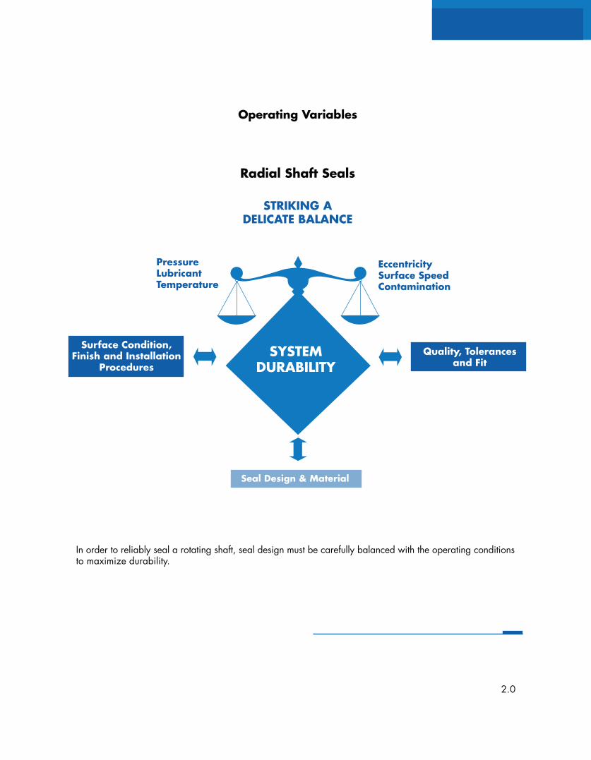
In order to reliably seal a rotating shaft, seal design must be carefully balanced with the operating conditionsto maximize durability.
Operating Variables
Radial Shaft Seals
Surface Condition,Finish and Installation
Procedures
Quality, Tolerancesand Fit
PressureLubricantTemperature
EccentricitySurface SpeedContamination
STRIKING ADELICATE BALANCE
Seal Design & Material
SYSTEMDURABILITY
2.0
Pressure
Simrit Radial Shaft Seals can be designedto handle pressures up to 150 psi. Mostcommon seals, such as those shown onpage iv, are designed for little or nointernal fluid pressure.
Sealing against contaminants
The use of a Simrit Radial Shaft seal with adust lip is recommended for sealingagainst the dirt, dust and moisture on theair side.
NOTE: Before installation, fill the spacebetween sealing lip and dust lip withgrease to +/- 40% of available space toensure lubrication of the dust lip and toavoid any corrosion on the shaft. Wewould like to recommend grease fromKluber Lubrication.
In order to combat an aggressive attackfrom contaminants, it is possible to use twoseals in tandem. For extreme conditions,standard combinations, labrynth seals andmodular sealing systems can be used.Please contact your Simrit representativefor assistance.
Speed
To determine the shaft’s surface speed “V”the following formula applies:
Shaft diameter D x Revolutions per min x pi V(m/s) = 60
Temperature
The temperature on the sealing edge ishigher than in the oil bath due to the rotationof the shaft and the corresponding frictionproduced.
Lubrication
An increase in the revolutions per minute,and consequently surface speed, equates tohigher heat. Good lubrication and diffusionof the heat are important factors to ensuringthe sealing edge falls within a permissibletemperature range. Neglect in these areasleads to:-High wear-Premature hardening of the sealing lip-Shortened seal life
Areas of Influence
2.1
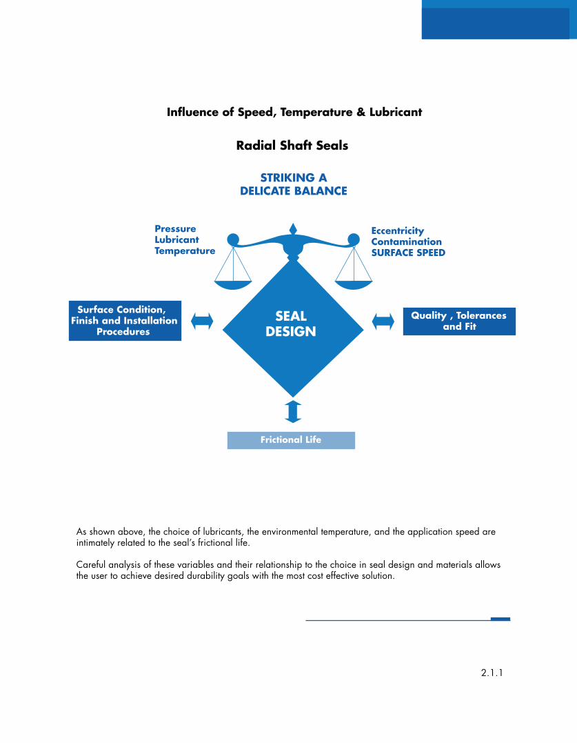
As shown above, the choice of lubricants, the environmental temperature, and the application speed areintimately related to the seal’s frictional life.
Careful analysis of these variables and their relationship to the choice in seal design and materials allowsthe user to achieve desired durability goals with the most cost effective solution.
Surface Condition,Finish and Installation Procedures
Surface Condition,Finish and Installation Procedures
Quality , Tolerances and Fit
PressureLubricantTemperature
EccentricityContaminationSURFACE SPEED
Influence of Speed, Temperature & Lubricant
Frictional Life
SEALDESIGN
Frictional Life
Radial Shaft Seals
STRIKING ADELICATE BALANCE
2.1.1
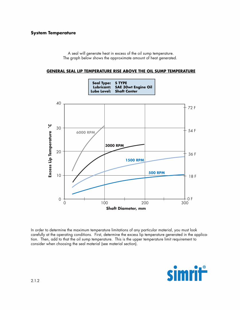
In order to determine the maximum temperature limitations of any particular material, you must lookcarefully at the operating conditions. First, determine the excess lip temperature generated in the applica-tion. Then, add to that the oil sump temperature. This is the upper temperature limit requirement toconsider when choosing the seal material (see material section).
System Temperature
A seal will generate heat in excess of the oil sump temperature.The graph below shows the approximate amount of heat generated.
GENERAL SEAL LIP TEMPERATURE RISE ABOVE THE OIL SUMP TEMPERATURE
Seal Type: S TYPELubricant: SAE 30wt Engine Oil
Lube Level: Shaft Center
2.1.2
Exce
ss L
ip T
emper
atu
re˚C
40
30
20
00 100
Shaft Diameter, mm
10
6000 RPM
3000 RPM
500 RPM
200 300
72 F
54 F
36 F
18 F
1500 RPM
0 F
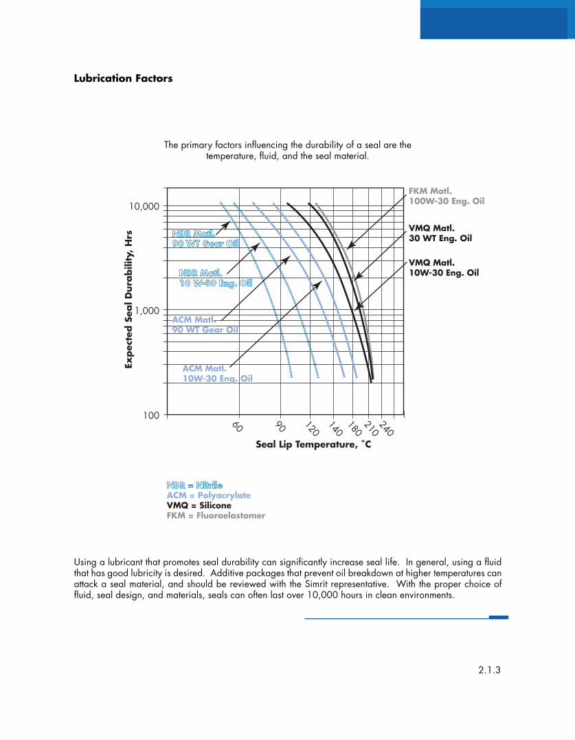
Using a lubricant that promotes seal durability can significantly increase seal life. In general, using a fluidthat has good lubricity is desired. Additive packages that prevent oil breakdown at higher temperatures canattack a seal material, and should be reviewed with the Simrit representative. With the proper choice offluid, seal design, and materials, seals can often last over 10,000 hours in clean environments.
Lubrication Factors
The primary factors influencing the durability of a seal are thetemperature, fluid, and the seal material.
2.1.3
Expec
ted S
eal D
ura
bili
ty,
Hrs
10,000
1,000
100 140
60
Seal Lip Temperature, ˚C
90 240
120
180210
VMQ Matl.10W-30 Eng. Oil
NBR Matl.90 WT Gear Oil
NBR Matl.10 W-30 Eng. Oil
VMQ Matl.30 WT Eng. Oil
FKM Matl.100W-30 Eng. Oil
ACM Matl.90 WT Gear Oil
ACM Matl.10W-30 Eng. Oil
ACM = PolyacrylateVMQ = SiliconeFKM = Fluoroelastomer
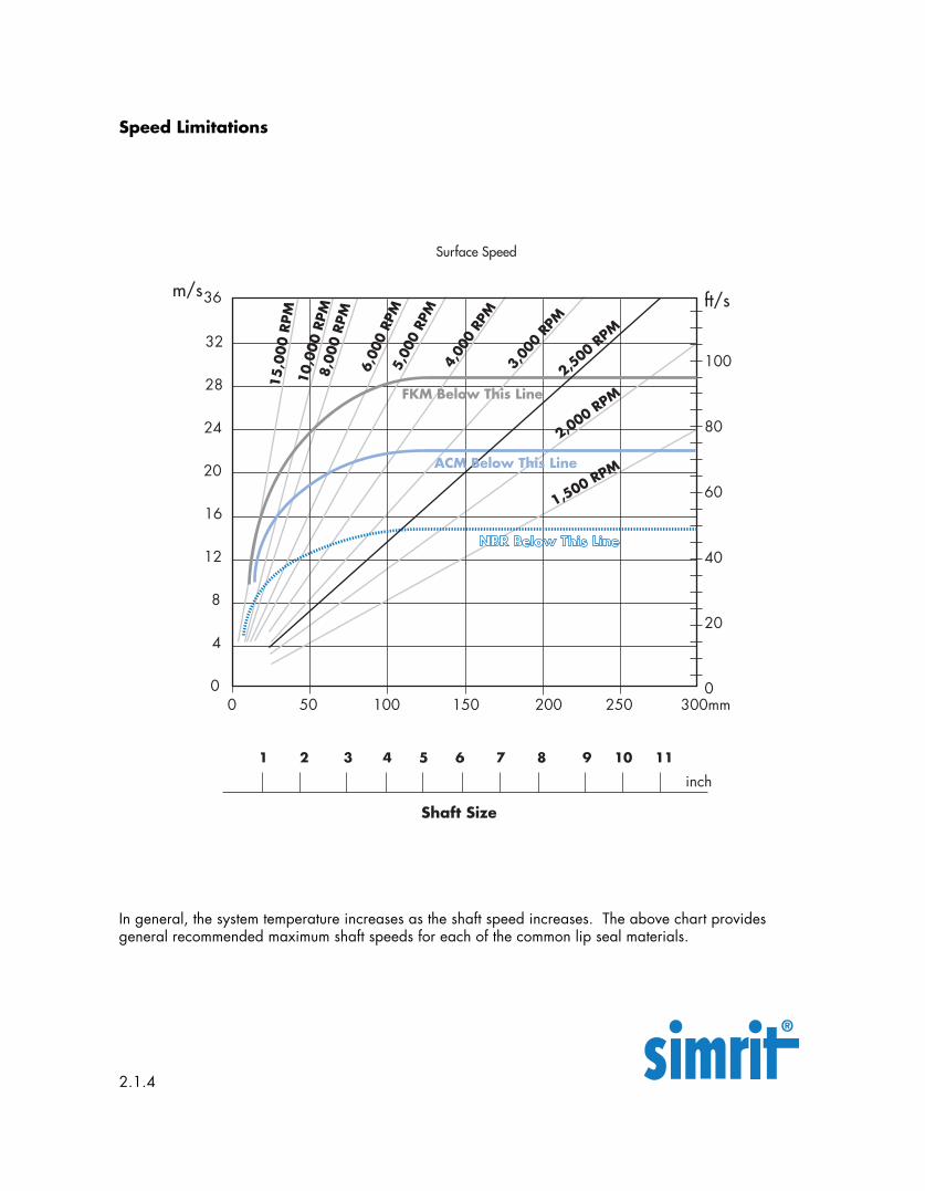
In general, the system temperature increases as the shaft speed increases. The above chart providesgeneral recommended maximum shaft speeds for each of the common lip seal materials.
Speed Limitations
2.1.4
36
20
28
16
0
Shaft Size
1 2 3 4 5 6 7 8 9 10 11
NBR Below This Line
m/s
0 100 250150 200 300mm500
40
20
60
100
8024
inch
15,0
00 R
PM
12
8
4
Surface Speed
ft/s10
,000
RPM
8,00
0 RP
M
6,00
0 RP
M5,
000
RPM
4,00
0 RP
M
3,00
0 RP
M
2,500 R
PM
2,000 RPM
1,500 RPMACM Below This Line
FKM Below This Line
32
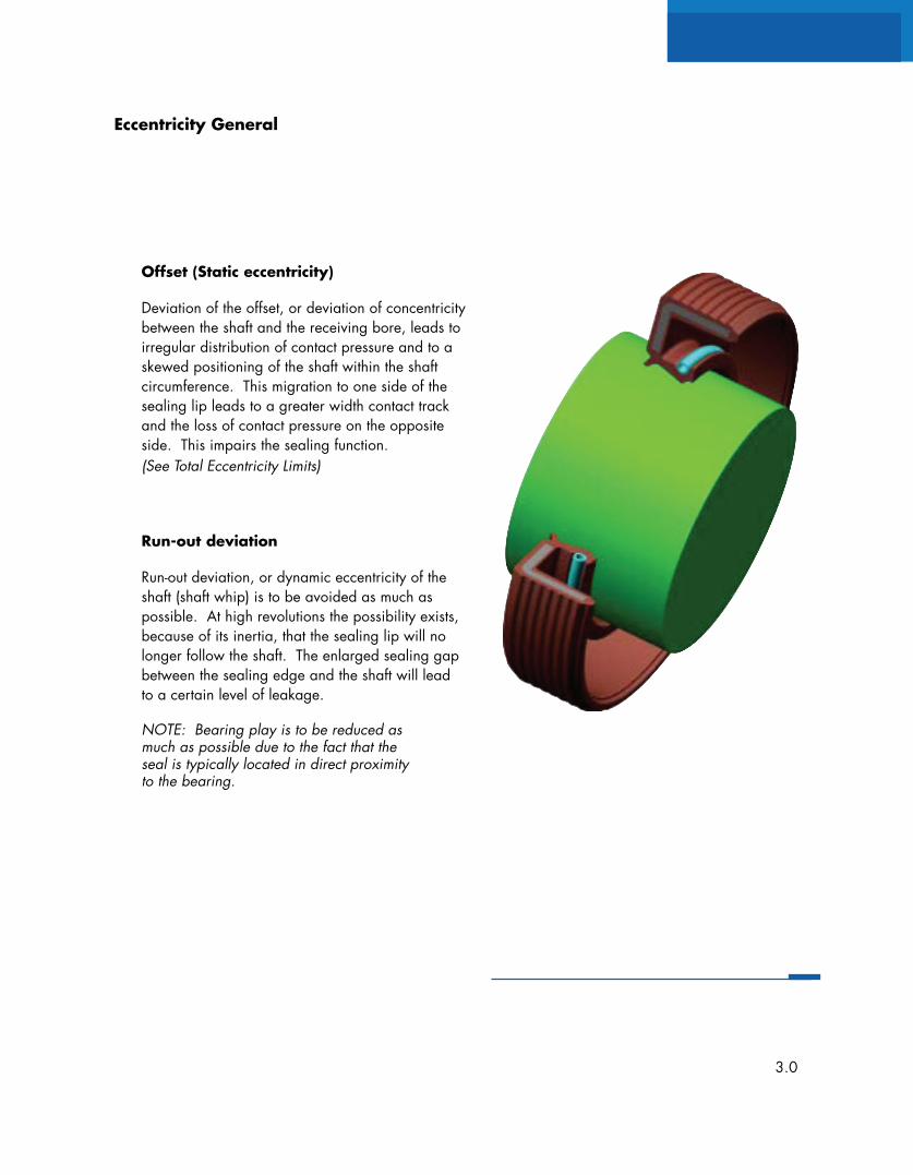
Offset (Static eccentricity)
Deviation of the offset, or deviation of concentricitybetween the shaft and the receiving bore, leads toirregular distribution of contact pressure and to askewed positioning of the shaft within the shaftcircumference. This migration to one side of thesealing lip leads to a greater width contact trackand the loss of contact pressure on the oppositeside. This impairs the sealing function.(See Total Eccentricity Limits)
Run-out deviation
Run-out deviation, or dynamic eccentricity of theshaft (shaft whip) is to be avoided as much aspossible. At high revolutions the possibility exists,because of its inertia, that the sealing lip will nolonger follow the shaft. The enlarged sealing gapbetween the sealing edge and the shaft will leadto a certain level of leakage.
NOTE: Bearing play is to be reduced asmuch as possible due to the fact that theseal is typically located in direct proximityto the bearing.
Eccentricity General
3.0
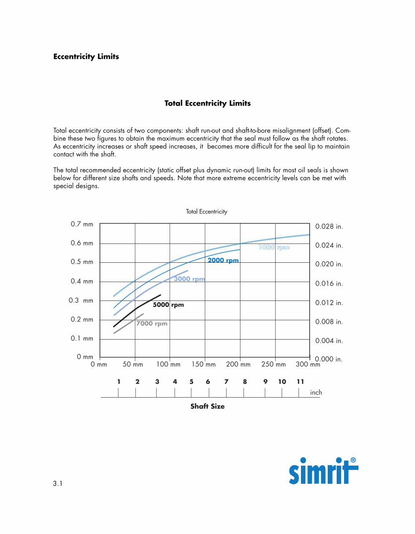
Total eccentricity consists of two components: shaft run-out and shaft-to-bore misalignment (offset). Com-bine these two figures to obtain the maximum eccentricity that the seal must follow as the shaft rotates.As eccentricity increases or shaft speed increases, it becomes more difficult for the seal lip to maintaincontact with the shaft.
The total recommended eccentricity (static offset plus dynamic run-out) limits for most oil seals is shownbelow for different size shafts and speeds. Note that more extreme eccentricity levels can be met withspecial designs.
Eccentricity Limits
Total Eccentricity Limits
3.1
0.5 mm
0.7 mm
0.4 mm
0 mm0 mm 100 mm 250 mm
0.2 mm 7000 rpm
3000 rpm
1000 rpm
2000 rpm
150 mm 200 mm 300 mm50 mm
0.1 mm
0.3 mm5000 rpm
Shaft Size
1 2 3 4 5 6 7 8 9 10 11
inch
Total Eccentricity
0.6 mm
0.020 in.
0.028 in.
0.016 in.
0.000 in.
0.008 in.
0.004 in.
0.012 in.
0.024 in.
Run-out and Offset
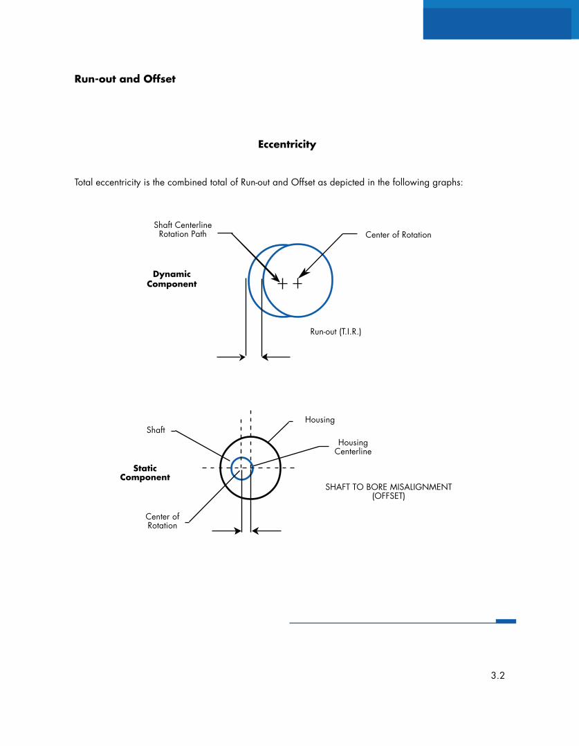
Total eccentricity is the combined total of Run-out and Offset as depicted in the following graphs:
Eccentricity
Shaft CenterlineRotation Path Center of Rotation
Run-out (T.I.R.)
DynamicComponent
Center ofRotation
StaticComponent
ShaftHousing
HousingCenterline
SHAFT TO BORE MISALIGNMENT(OFFSET)
3.2
Surface Condition,Finish and Installation
Procedures
Quality, Tolerancesand Fit
PressureLubricantTemperature
EccentricitySurface SpeedContamination
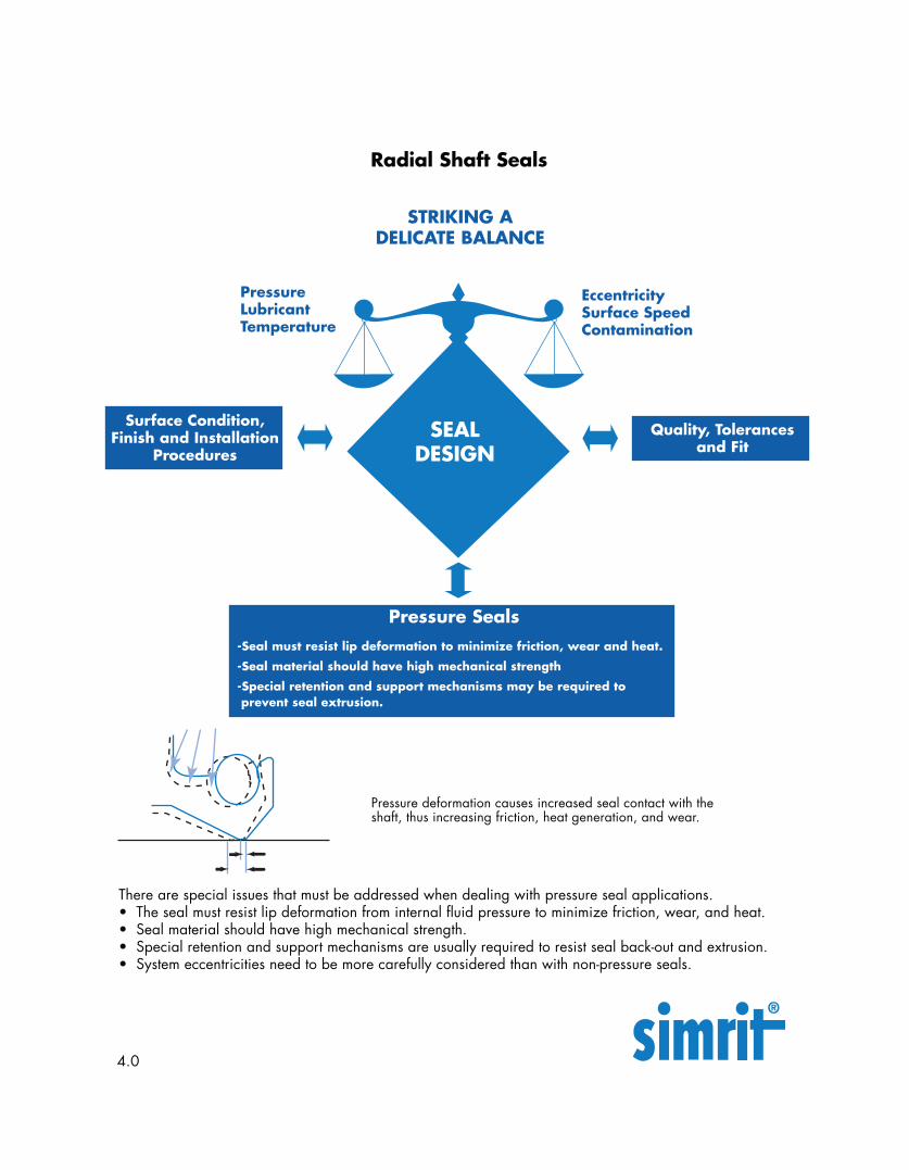
Pressure Seals-Seal must resist lip deformation to minimize friction, wear and heat.
-Seal material should have high mechanical strength
-Special retention and support mechanisms may be required to prevent seal extrusion.
SEALDESIGN
Pressure deformation causes increased seal contact with theshaft, thus increasing friction, heat generation, and wear.
There are special issues that must be addressed when dealing with pressure seal applications.• The seal must resist lip deformation from internal fluid pressure to minimize friction, wear, and heat.• Seal material should have high mechanical strength.• Special retention and support mechanisms are usually required to resist seal back-out and extrusion.• System eccentricities need to be more carefully considered than with non-pressure seals.
Radial Shaft Seals
STRIKING ADELICATE BALANCE
4.0
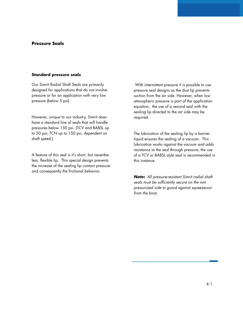
Standard pressure seals
Our Simrit Radial Shaft Seals are primarilydesigned for applications that do not involvepressure or for an application with very lowpressure (below 5 psi).
However, unique to our industry, Simrit doeshave a standard line of seals that will handlepressures below 150 psi. (TCV and BABSL upto 50 psi; TCN up to 150 psi, dependent onshaft speed.)
A feature of this seal is it’s short, but neverthe-less, flexible lip. This special design preventsthe increase of the sealing lip contact pressureand consequently the frictional behavior.
With intermittent pressure it is possible to usepressure seal designs as the dust lip preventssuction from the air side. However, when lowatmospheric pressure is part of the applicationequation, the use of a second seal with thesealing lip directed to the air side may berequired.
The lubrication of the sealing lip by a barrierliquid ensures the sealing of a vacuum. Thislubrication works against the vacuum and addsresistance to the seal through pressure; the useof a TCV or BABSL style seal is recommended inthis instance.
Note: All pressure-resistant Simrit radial shaftseals must be sufficiently secure on the nonpressurized side to guard against squeeze-outfrom the bore.
Pressure Seals
4.1
Pressure (psi)
125
75100
50
00 10 30
Shaft Speed (ft/sec)
25
TCN
TC
TCV
150
15 20 355 25
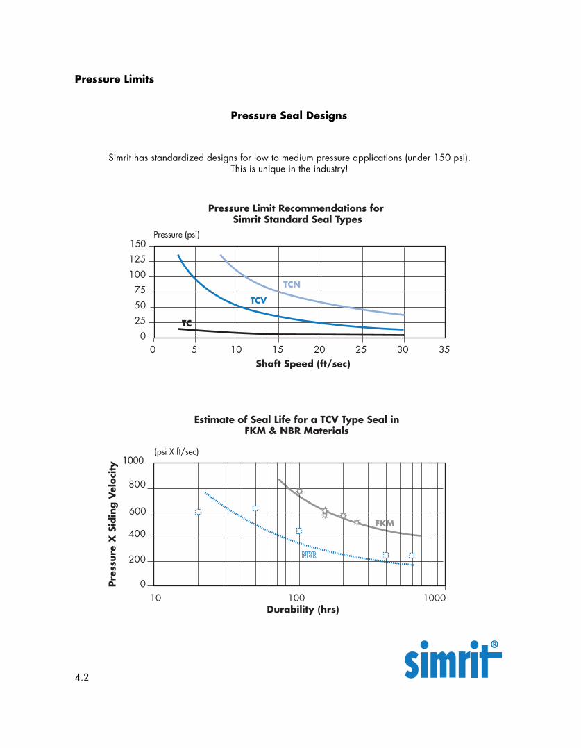
Pressure Limit Recommendations for Simrit Standard Seal Types
Pres
sure
X S
idin
g V
eloc
ity
800
400
600
200
10Durability (hrs)
0
1000
100 1000
Estimate of Seal Life for a TCV Type Seal inFKM & NBR Materials
FKM
(psi X ft/sec)
Pressure Limits
Simrit has standardized designs for low to medium pressure applications (under 150 psi).This is unique in the industry!
Pressure Seal Designs
4.2
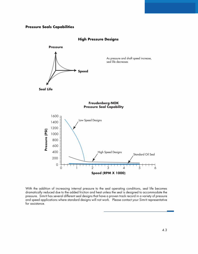
Pressure
Speed
Seal Life
Freudenberg-NOKPressure Seal Capability
As pressure and shaft speed increase,seal life decreases
Low Speed Designs
High Speed DesignsStandard Oil Seal
Speed (RPM X 1000)
600
400
00 2
200
43
800
1000
1200
1400
1600
1 5 6
Pres
sure
(PS
I)
Pressure Seals Capabilities
With the addition of increasing internal pressure to the seal operating conditions, seal life becomesdramatically reduced due to the added friction and heat unless the seal is designed to accommodate thepressure. Simrit has several different seal designs that have a proven track record in a variety of pressureand speed applications where standard designs will not work. Please contact your Simrit representativefor assistance.
High Pressure Designs
4.3
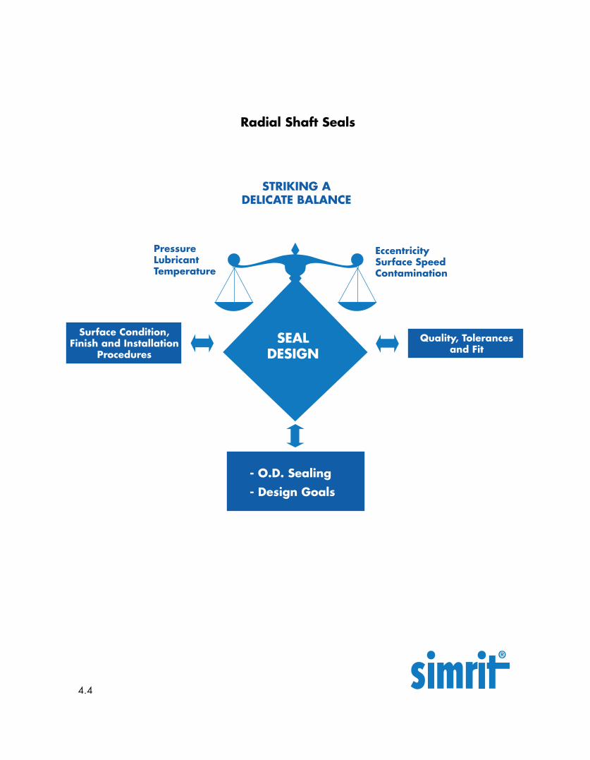
Surface Condition,Finish and Installation
Procedures
Quality, Tolerancesand Fit
PressureLubricantTemperature
EccentricitySurface SpeedContamination
- O.D. Sealing
- Design Goals
SEALDESIGN
Radial Shaft Seals
STRIKING ADELICATE BALANCE
4.4
4.5
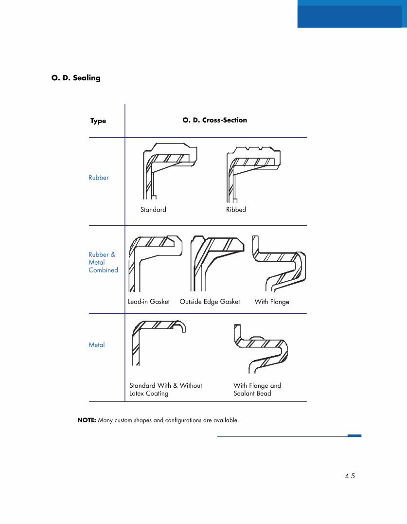
O. D. Sealing
RibbedStandard
Lead-in Gasket Outside Edge Gasket With Flange
With Flange andSealant Bead
Standard With & WithoutLatex Coating
Rubber
Rubber &MetalCombined
Metal
Type O. D. Cross-Section
NOTE: Many custom shapes and configurations are available.
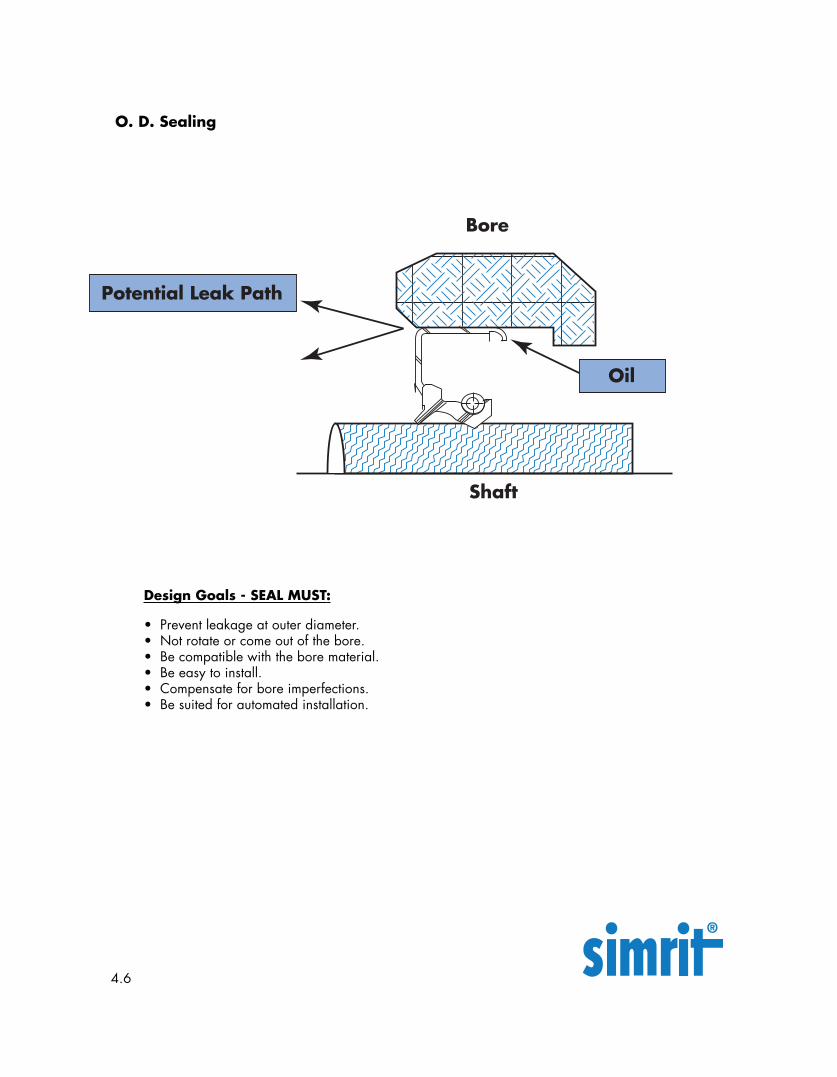
O. D. Sealing
Design Goals - SEAL MUST:
• Prevent leakage at outer diameter.• Not rotate or come out of the bore.• Be compatible with the bore material.• Be easy to install.• Compensate for bore imperfections.• Be suited for automated installation.
4.6
Shaft
Bore
Potential Leak Path
Oil
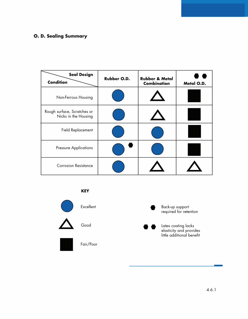
O. D. Sealing Summary
KEY
Excellent
Good
Fair/Poor
Back-up supportrequired for retention
Latex coating lackselasticity and provideslittle additional benefit
Non-Ferrous Housing
Rough surface, Scratches orNicks in the Housing
Field Replacement
Pressure Applications
Corrosion Resistance
Seal Design
ConditionRubber O.D. Rubber & Metal
Combination Metal O.D.
4.6.1
Surface Condition,Finish and Installation
Procedures
Quality, Tolerancesand Fit
PressureLubricantTemperature
EccentricitySurface SpeedContamination
SURFACEFINISH
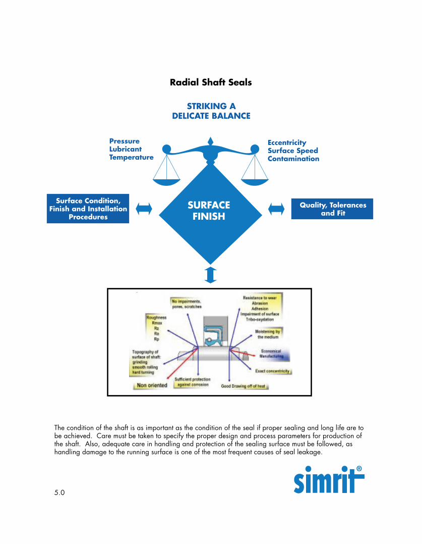
The condition of the shaft is as important as the condition of the seal if proper sealing and long life are tobe achieved. Care must be taken to specify the proper design and process parameters for production ofthe shaft. Also, adequate care in handling and protection of the sealing surface must be followed, ashandling damage to the running surface is one of the most frequent causes of seal leakage.
Radial Shaft Seals
STRIKING ADELICATE BALANCE
5.0
Structure of the Shaft
The structure of the shaft as it relates to thesurface area at point of contact with the sealinglip, directly impacts the function of the seal andthe durability of the sealing system.
Surface roughness
When the depth of roughness is too low (especiallywith higher surface speed), the potential forproblems exist due to the inability of the lubricantto effectively reach the sealing edge. This canresult in premature hardening and the formationof cracks and possibly signs of combustion on thesealing edge.
When the depth of roughness is too high thepotential for problems exists with excessivepremature wear and possible leakage within thesealing system. (See Recommended ShaftConditions)
Plunge Grinding
The recommended procedure in shaft preparationis plunge grinding. This is to ensure the desirednon-oriented state of the shaft. (Plunge GrindProcess)
Shaft Materials
Suitable materials to ensure the proper function ofour Simrit Radial Shaft seals are:
-The steel usually found in mechanical engineering,e.g. C35 and C45
-Casting materials such as ball graphite andmalleable iron.
-Sprayed on metal coatings
-Coatings applied through CVD and PVD processes,as well as, anodized coatings positively assessed
The adherence to values for roughness and a goodadhesion to the base material are prerequisites.
Note generally suitable are:
-Hard chrome coatings
-Plastic materials
Shaft impairment
Scratches, pressure sites, rust and other damageon the seal’s running surface ultimately leads toleakage problems.
Note: Great care in protecting the shaft duringproduction and through to final assembly isrecommended. This can be accomplished byusing protective sleeves and special transportingdevices.
Structure of the Shaft
5.1
Conditions
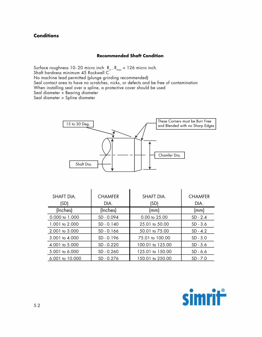
Recommended Shaft Condition
Surface roughness 10- 20 micro inch Ra , Rmax < 126 micro inch.Shaft hardness minimum 45 Rockwell CNo machine lead permitted (plunge grinding recommended)Seal contact area to have no scratches, nicks, or defects and be free of contaminationWhen installing seal over a spline, a protective cover should be usedSeal diameter < Bearing diameterSeal diameter > Spline diameter
SHAFT DIA. CHAMFER SHAFT DIA. CHAMFER(SD) DIA. (SD) DIA.
(Inches) (Inches) (mm) (mm)0.000 to 1.000 SD - 0.094 0.00 to 25.00 SD - 2.41.001 to 2.000 SD - 0.140 25.01 to 50.00 SD - 3.62.001 to 3.000 SD - 0.166 50.01 to 75.00 SD - 4.23.001 to 4.000 SD - 0.196 75.01 to 100.00 SD - 5.04.001 to 5.000 SD - 0.220 100.01 to 125.00 SD - 5.65.001 to 6.000 SD - 0.260 125.01 to 150.00 SD - 6.66.001 to 10.000 SD - 0.276 150.01 to 250.00 SD - 7.0
These Corners must be Burr Freeand Blended with no Sharp Edges
Chamfer Dia.
15 to 30 Deg.
Shaft Dia.
5.2
Plunge Turning
Bead Blasting
Turning
FinishingProcesses
Honing /Superfinishing
Deep DrawnMetal Sheet
Paper Polishing
4-AxesMachining
PlungeGrinding
Quick PointGrinding
Roller Burnishing
Polishing
Plunge Grinding
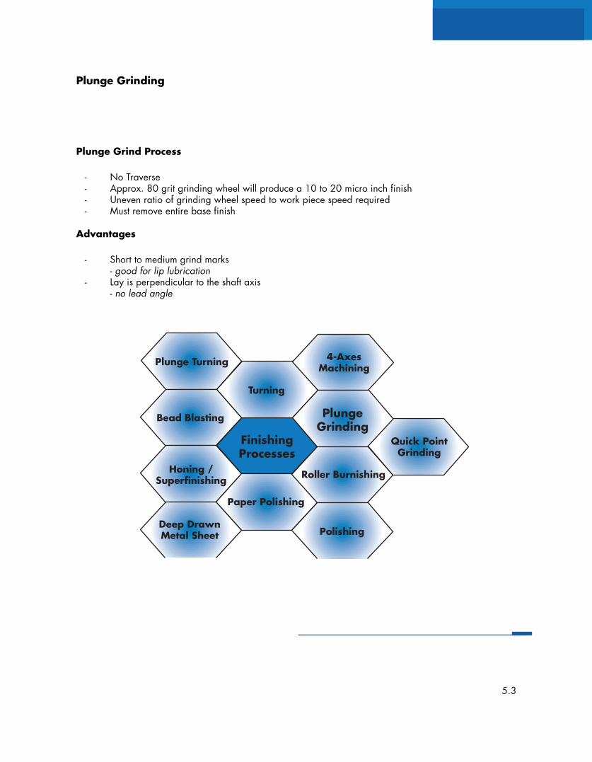
Plunge Grind Process
- No Traverse- Approx. 80 grit grinding wheel will produce a 10 to 20 micro inch finish- Uneven ratio of grinding wheel speed to work piece speed required- Must remove entire base finish
Advantages
- Short to medium grind marks- good for lip lubrication
- Lay is perpendicular to the shaft axis- no lead angle
5.3
Housings
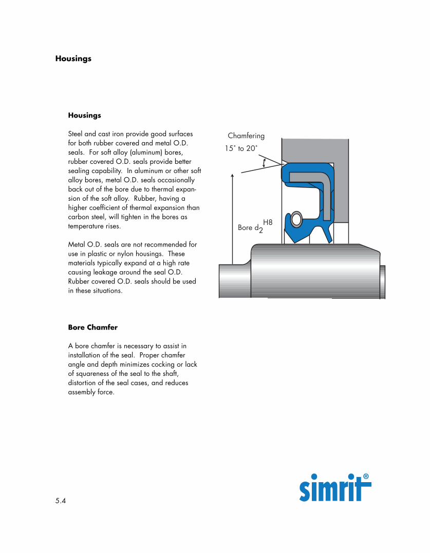
Steel and cast iron provide good surfacesfor both rubber covered and metal O.D.seals. For soft alloy (aluminum) bores,rubber covered O.D. seals provide bettersealing capability. In aluminum or other softalloy bores, metal O.D. seals occasionallyback out of the bore due to thermal expan-sion of the soft alloy. Rubber, having ahigher coefficient of thermal expansion thancarbon steel, will tighten in the bores astemperature rises.
Metal O.D. seals are not recommended foruse in plastic or nylon housings. Thesematerials typically expand at a high ratecausing leakage around the seal O.D.Rubber covered O.D. seals should be usedin these situations.
Bore Chamfer
A bore chamfer is necessary to assist ininstallation of the seal. Proper chamferangle and depth minimizes cocking or lackof squareness of the seal to the shaft,distortion of the seal cases, and reducesassembly force.
Housings
5.4
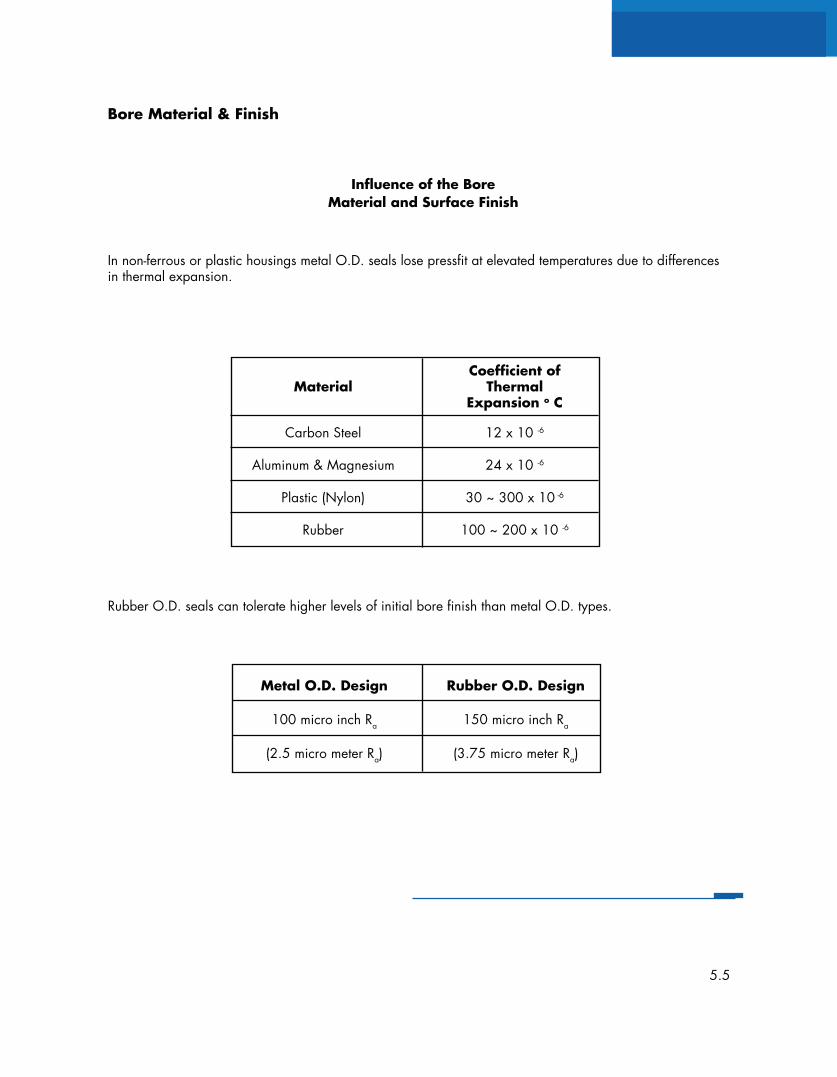
Bore Material & Finish
Rubber O.D. seals can tolerate higher levels of initial bore finish than metal O.D. types.
In non-ferrous or plastic housings metal O.D. seals lose pressfit at elevated temperatures due to differencesin thermal expansion.
Influence of the BoreMaterial and Surface Finish
Coefficient ofMaterial Thermal
Expansion o C
Carbon Steel 12 x 10 -6
Aluminum & Magnesium 24 x 10 -6
Plastic (Nylon) 30 ~ 300 x 10 -6
Rubber 100 ~ 200 x 10 -6
Metal O.D. Design Rubber O.D. Design
100 micro inch Ra 150 micro inch Ra
(2.5 micro meter Ra) (3.75 micro meter Ra)
5.5
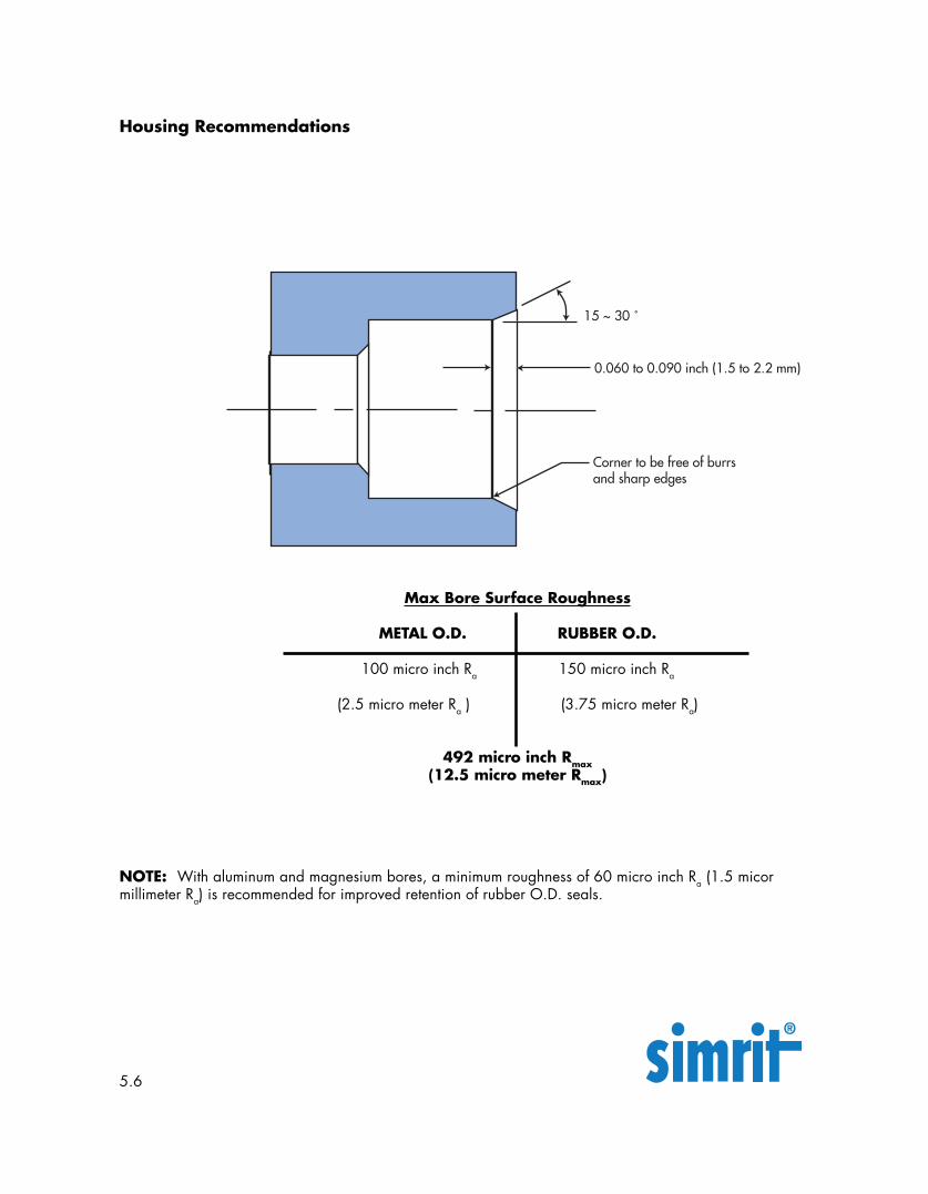
Corner to be free of burrsand sharp edges
0.060 to 0.090 inch (1.5 to 2.2 mm)
15 ~ 30 ˚
Housing Recommendations
NOTE: With aluminum and magnesium bores, a minimum roughness of 60 micro inch Ra (1.5 micormillimeter Ra) is recommended for improved retention of rubber O.D. seals.
Max Bore Surface Roughness
METAL O.D. RUBBER O.D.
100 micro inch Ra 150 micro inch Ra
(2.5 micro meter Ra ) (3.75 micro meter Ra)
492 micro inch Rmax(12.5 micro meter Rmax)
5.6
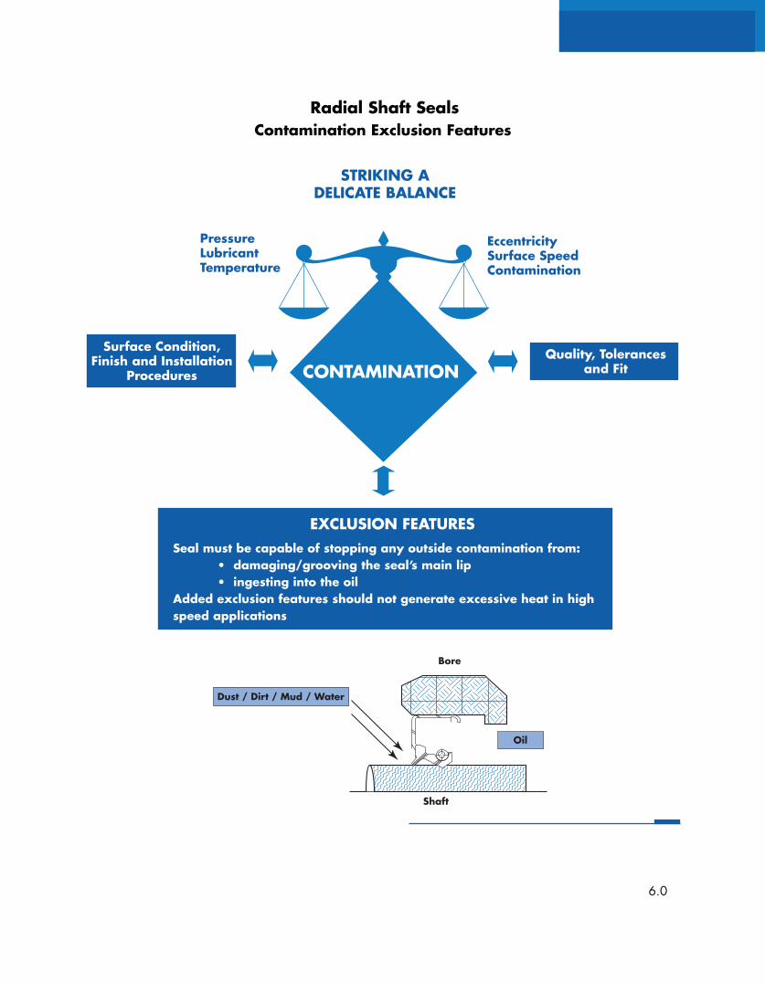
Shaft
Bore
Oil
Dust / Dirt / Mud / Water
Surface Condition,Finish and Installation
Procedures
Quality, Tolerancesand Fit
PressureLubricantTemperature
EccentricitySurface SpeedContamination
CONTAMINATION
Radial Shaft Seals
STRIKING ADELICATE BALANCE
Contamination Exclusion Features
EXCLUSION FEATURESSeal must be capable of stopping any outside contamination from: • damaging/grooving the seal’s main lip • ingesting into the oilAdded exclusion features should not generate excessive heat in highspeed applications
6.0
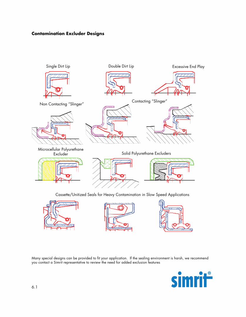
Contamination Excluder Designs
Single Dirt Lip Double Dirt Lip
Non Contacting “Slinger”Contacting “Slinger”
Excessive End Play
Microcellular PolyurethaneExcluder Solid Polyurethane Excluders
Cassette/Unitized Seals for Heavy Contamination in Slow Speed Applications
Many special designs can be provided to fit your application. If the sealing environment is harsh, we recommendyou contact a Simrit representative to review the need for added exclusion features
6.1
Surface Condition,Finish and Installation
Procedures
Quality, Tolerancesand Fit
PressureLubricantTemperature
EccentricitySurface SpeedContamination
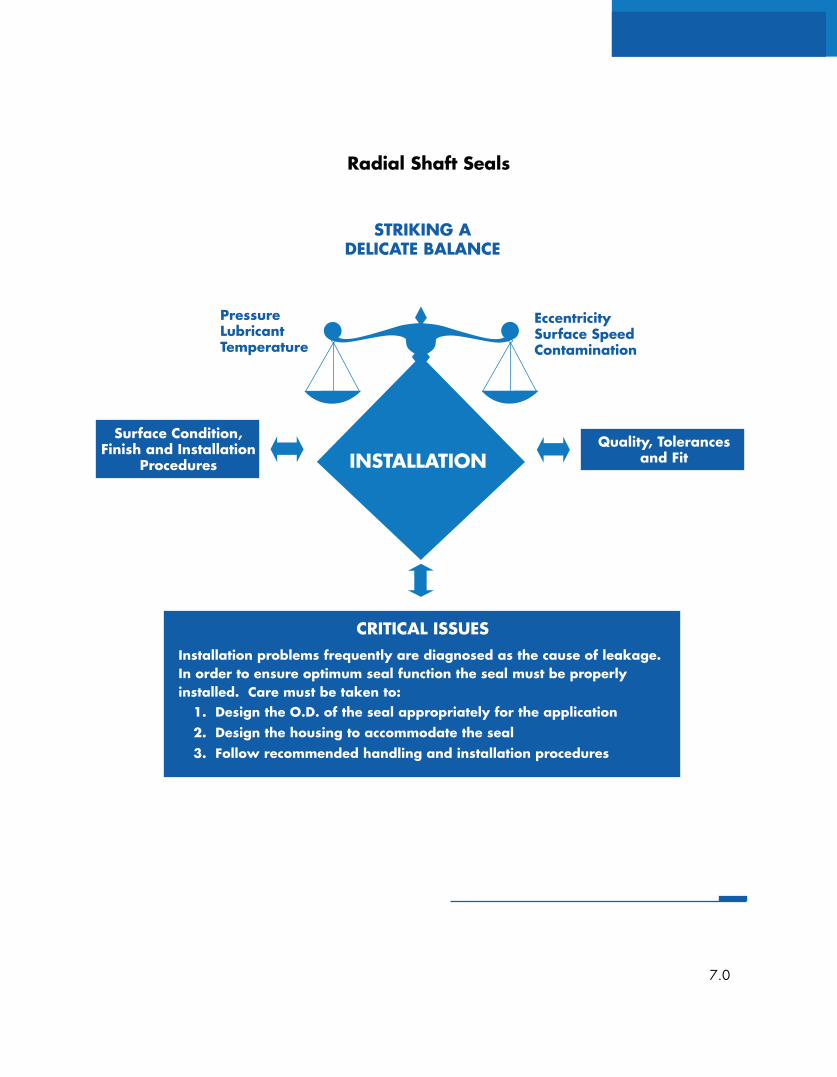
INSTALLATION
Radial Shaft Seals
STRIKING ADELICATE BALANCE
CRITICAL ISSUESInstallation problems frequently are diagnosed as the cause of leakage.In order to ensure optimum seal function the seal must be properlyinstalled. Care must be taken to:
1. Design the O.D. of the seal appropriately for the application2. Design the housing to accommodate the seal3. Follow recommended handling and installation procedures
7.0
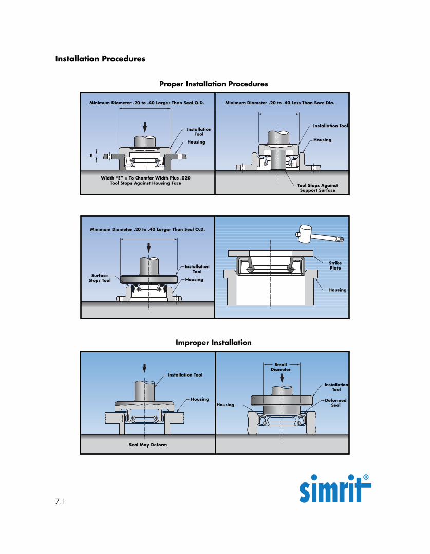
Installation Procedures
7.1
Improper Installation
Proper Installation Procedures
Minimum Diameter .20 to .40 Larger Than Seal O.D.
InstallationTool
Housing
Width “E” = To Chamfer Width Plus .020Tool Stops Against Housing Face
Minimum Diameter .20 to .40 Less Than Bore Dia.
Installation Tool
Housing
Tool Stops AgainstSupport Surface
Minimum Diameter .20 to .40 Larger Than Seal O.D.
SurfaceStops Tool
InstallationTool
Housing
Housing
StrikePlate
E
Seal May Deform
Installation Tool
Housing DeformedSeal
InstallationTool
Housing
SmallDiameter
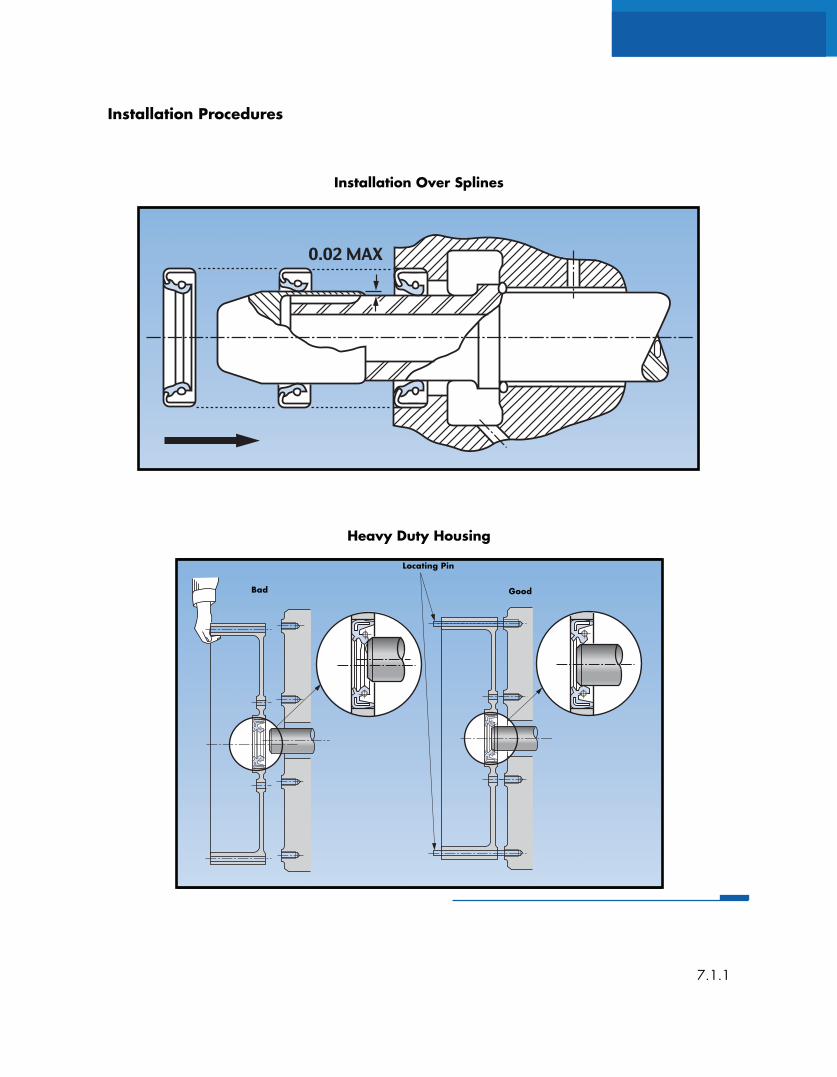
Installation Procedures
7.1.1
Installation Over Splines
Heavy Duty Housing
Good
Locating Pin
Bad
Installation Procedures
7.1.2
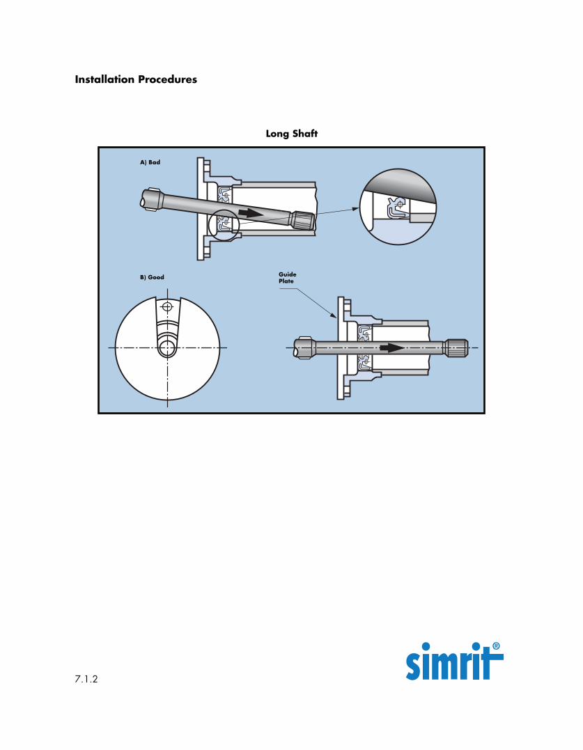
Long Shaft
B) Good GuidePlate
A) Bad
Leakage - General
Leakage
There are different and varying terms to definewhat is classified as “leakage”.
Watertight: No moisture on seal
Moist: bead of moisture in sealing edge area limiting the function, but not going beyond back surface
area
Wet: bead of moisture going beyond back surface area with the formation
of droplets, but not dripping
MeasurableLeakage: small beads of moisture on
outside of housing coming fromthe back of the seal
PassingLeakage: short-term problem within the sealing system, e.g. caused by
small dirt particles under thesealing edge which will washaway with further use.
ApparentLeakage: passing leakage which leads
back to the grease filling be-tween the sealing lip and dustlip. The overflowing greaseappears as apparent leakageon the outside.
Causes for measurable leakage can be:
-Varied expansion of seal and housing on thestatic side by non-adherence to tolerances.
-Cracks in the material, above all in the sealingedge due to exceeding seal operating limita-tions.
-Increasing hardness of rubber caused byexceeding seal working parameters andincompatibility with the media being sealed.
-Corrosion from the shaft up to the sealingedge.
-Failure of lubrication thereby seal runs dry;result is excessive wear on the sealing lip.
-Formation of “oil carbons” in the sealing edgearea.
-Vibration of the unit and shaft to such an extentthat the sealing lip can no longer follow.
-Permanent ingress of dirt on the sealing lipfrom either inside the chamber or out.
-Damage due to handling or installation.
8.0
Leakage - General
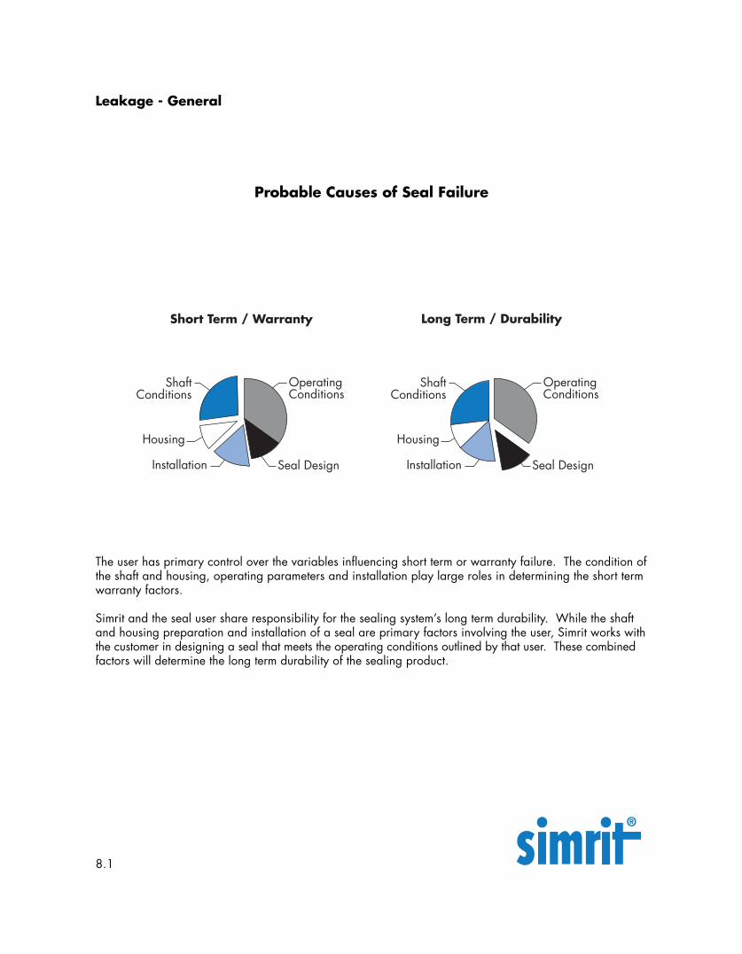
The user has primary control over the variables influencing short term or warranty failure. The condition ofthe shaft and housing, operating parameters and installation play large roles in determining the short termwarranty factors.
Simrit and the seal user share responsibility for the sealing system’s long term durability. While the shaftand housing preparation and installation of a seal are primary factors involving the user, Simrit works withthe customer in designing a seal that meets the operating conditions outlined by that user. These combinedfactors will determine the long term durability of the sealing product.
Probable Causes of Seal Failure
8.1
Leakage - General
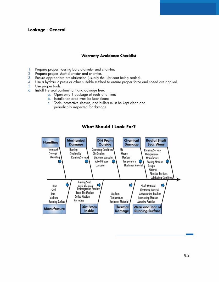
1. Prepare proper housing bore diameter and chamfer.2. Prepare proper shaft diameter and chamfer.3. Ensure appropriate prelubrication (usually the lubricant being sealed).4. Use a hydraulic press or other suitable method to ensure proper force and speed are applied.5. Use proper tools.6. Install the seal contaminant and damage free:
a. Open only 1 package of seals at a time;b. Installation area must be kept clean;c. Tools, protective sleeves, and bullets must be kept clean and
periodically inspected for damage.
Warranty Avoidance Checklist
What Should I Look For?
8.2
Running SurfaceOverpressureManufactureSealing MediumDesignMaterialAbrasive ParticlesLubricating Conditions
UVOzoneMediumTemperatureElastomer Material
Operating ConditionsDirt SealingElastomer AbrasionSoiled GreaseCorrosion
HousingSealing LipRunning Surface
TransportStorageMounting
Casting SandMetal AbrasionDisintegration Products
From The MediumSoiled Medium
Corrosion
UnitSeal
BoreMedium
Running Surface
MediumTemperature
Elastomer Material
Shaft MaterialElastomer Material
Anticorrosion ProductLubricating Medium
Abrasive Particles
Wear and Tear ofRunning Surface
ThermalDamage
Dirt FromInsideManufacture
Handling Radial ShaftSeal Wear
ChemicalDamage
MechanicalDamage
Dirt FromOutside
Defect Sources
Defect Source:
Possible Defect:
Consequence:
Weak spot:
Remedial Action
Defect Source:
Possible Defect:
Consequence:
Weak spot:
Remedial Action
Damage to packaging
Contamination of Shaft Seals
Shortened service life or immediate leakage
Packaging not satisfactory
Set procedures for inspection of parts for contamination,visual and dimensional changes, handling; optimizepackaging.
Damage to packagingNon-adherence to storage guidelines
Fitting and employment of contaminated shaft seals
No effect up to immediate leakage and possible short-ened working life.
Non-adherence to storage conditions
Definite adherence to storage conditions
Incoming Goods:
Defect source and recommended remedial measures
Storage
9.0
Defect Source:
Possible Defect:
Consequence:
Weak spot:
Remedial Action
Defect Source:
Possible Defect:
Consequence:
Weak spot:
Remedial Action
Contamination of Shaft Seals
Fitting and employment of contaminated seals
Shortened service life or immediate leakage
Dust and dirt
Cleaning with suitable cleaning agent before installation,original packaging to be opened only at installation site.
Damaged shaft seal
Installation of impaired shaft seals
Immediate leakage or shortened working life
Premature aging through improper storage
Original packaging to be opened only at installation site
Storage Cont’d.
Defect source and recommended remedial measures
Storage Cont’d.
9.0.1
Defect Sources
Defect Source:
Possible Defect:
Consequence:
Weak spot:
Remedial Action
Defect Source:
Possible Defect:
Consequence:
Weak spot:
Remedial Action
Open storing of pre-greased shaft seals
Contamination of grease
Shortened service life or immediate leakage
Dust and dirt from surroundings
Always cover packaging unit, protect from dust and dirt,only draw the needed quantity for use
Unsuitable stock container
Contamination, impairment of shaft seals, springs comingloose
Immediate leakage or shortened working life
Collection of dirt and moisture in the stocking container,sharp edges
Use containers that are open and lightly cleaned. Nosharp edges
Storage Cont’d.
Defect source and recommended remedial measures
Storage Cont’d.
9.0.2
Defect Sources
Defect Source:
Possible Defect:
Consequence:
Weak spot:
Remedial Action
Defect Source:
Possible Defect:
Consequence:
Weak spot:
Remedial Action
Improper opening or withdrawing from package
Cuts or similar damage on O.D. Loss of spring
Shortened service life or immediate leakage
Unsuitable tools or methods for opening
Suitable tooling for opening packages, special andcareful handling by installer
Using contaminated grease when pre-greasing shaft seal
Contamination, impairment of shaft seals
Immediate leakage or shortened working life
Dirt and dust
Grease container to be protected from dust and dirt andsealed off when not in use
Preparing for Installation:
Defect source and recommended remedial measures
Preparing for Installation:
9.0.3
Defect Sources
Defect Source:
Possible Defect:
Consequence:
Weak spot:
Remedial Action
Defect Source:
Possible Defect:
Consequence:
Weak spot:
Remedial Action
Unsuitable oil for moistening of shaft prior to shaft sealpress fit
Chemical influence on seal material, stick-slip
Shortened service life due to accelerated wear
Unfavorable lubrication, no oil in contact with Simrit shaftseal material
Consult Simrit Representative about oil grade. DO NOTUSE GRAPHITE GREASE
Too much grease between sealing edge and dust lip
Appearance of grease when installing or during operation
“Apparent leakage”
Incorrect amount of grease
Maximum grease amount: +/- 40% of greasing space
Preparing for Installation:
Defect source and recommended remedial measures
Preparing for Installation:
9.0.4
Defect Sources
Radial Shaft Seals
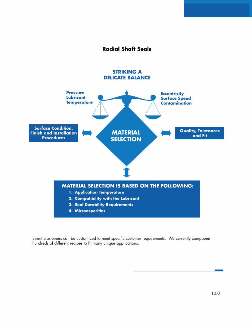
Simrit elastomers can be customized to meet specific customer requirements. We currently compoundhundreds of different recipes to fit many unique applications.
Surface Condition,Finish and Installation
Procedures
Quality, Tolerancesand Fit
PressureLubricantTemperature
EccentricitySurface SpeedContamination
MATERIALSELECTION
STRIKING ADELICATE BALANCE
MATERIAL SELECTION IS BASED ON THE FOLLOWING:1. Application Temperature2. Compatibility with the Lubricant3. Seal Durability Requirements4. Microasperities
10.0
Media to be Sealed
Medium and selection of material
The medium to be sealed determines the selec-tion of Simrit material and also the selection ofthe seal to be used.
Sealing is possible against liquid, vapor and inexceptional cases, even low viscosity andgaseous media.
Simrit materials can seal against various lubricat-ing substances, e.g .:
-Mineral oils-Synthetic oils-Greases based on mineral oils-Synthetic greases-Hydraulic oils-Highly inflammable pressurized liquids-Silicone oils with low lubricating properties
Under special circumstances, Simrit materials canseal against low lubricating, aggressive media,e.g.:
-Acids-Alkalis-Organic solvents
Reactions between media and Simritmaterials
Chemical influences of the media on Simritmaterials are crucial. Chemical reactions areaccelerated by increased temperatures. Materi-als of any sort can harden or soften due to themedia exposure.
-Hardening by ageing process caused by media
-Softening through swelling caused by themedia.
Upper limit conditions
The limits imposed on applications for the Simritradial shaft seal are reached and exceededwhen several conditions meet the upper operat-ing limits; such as:
-The maximum permitted surface speed-The maximum permitted temperature-Pressure resistance-Sparce lubrication or reduced heat dissipation.
10.1
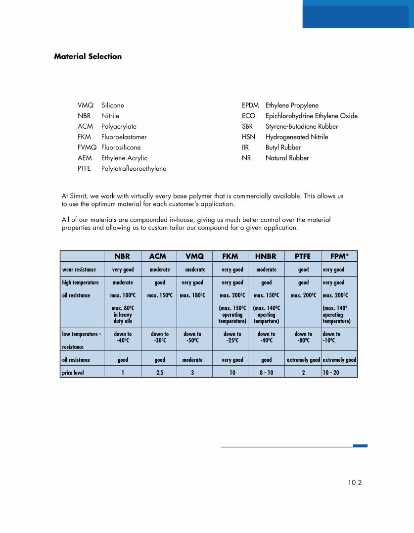
VMQ SiliconeNBR NitrileACM PolyacrylateFKM FluoroelastomerFVMQ FluorosiliconeAEM Ethylene AcrylicPTFE Polytetrafluoroethylene
At Simrit, we work with virtually every base polymer that is commercially available. This allows usto use the optimum material for each customer’s application.
All of our materials are compounded in-house, giving us much better control over the materialproperties and allowing us to custom tailor our compound for a given application.
EPDM Ethylene PropyleneECO Epichlorohydrine Ethylene OxideSBR Styrene-Butadiene RubberHSN Hydrogeneated NitrileIIR Butyl RubberNR Natural Rubber
Material Selection
NBR ACM VMQ FKM HNBR PTFE FPM*
wear resistance very good moderate moderate very good moderate good very good
high temperature moderate good very good very good good good very good
oil resistance max. 1000C max. 1500C max. 1800C max. 2000C max. 1500C max. 2000C max. 2000C
max. 800C (max. 1500C (max. 1400C (max. 1400
in heavy operating operting operatingduty oils temperature) temperture) temperature)
low temperature - down to down to down to down to down to down to down to-400C -300C -500C -250C -400C -800C -100C
resistance
oil resistance good good moderate very good good extremely good extremely good
price level 1 2.5 3 10 8 - 10 2 10 - 20
10.2
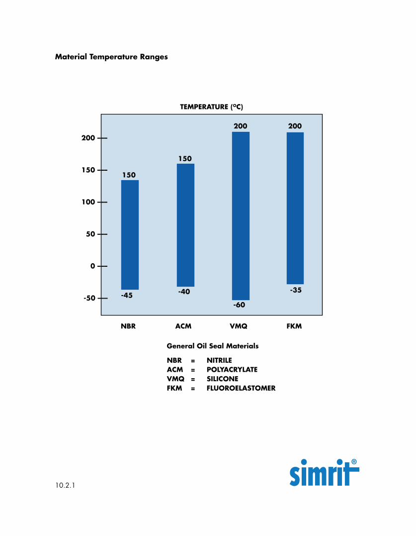
TEMPERATURE (OC)
NBR = NITRILEACM = POLYACRYLATEVMQ = SILICONEFKM = FLUOROELASTOMER
General Oil Seal Materials
Material Temperature Ranges
NBR ACM VMQ FKM
200 200
150
200 –––
150 –––
100 –––
50 –––
0 –––
-50 ––– -45-35-40
10.2.1
-60
150
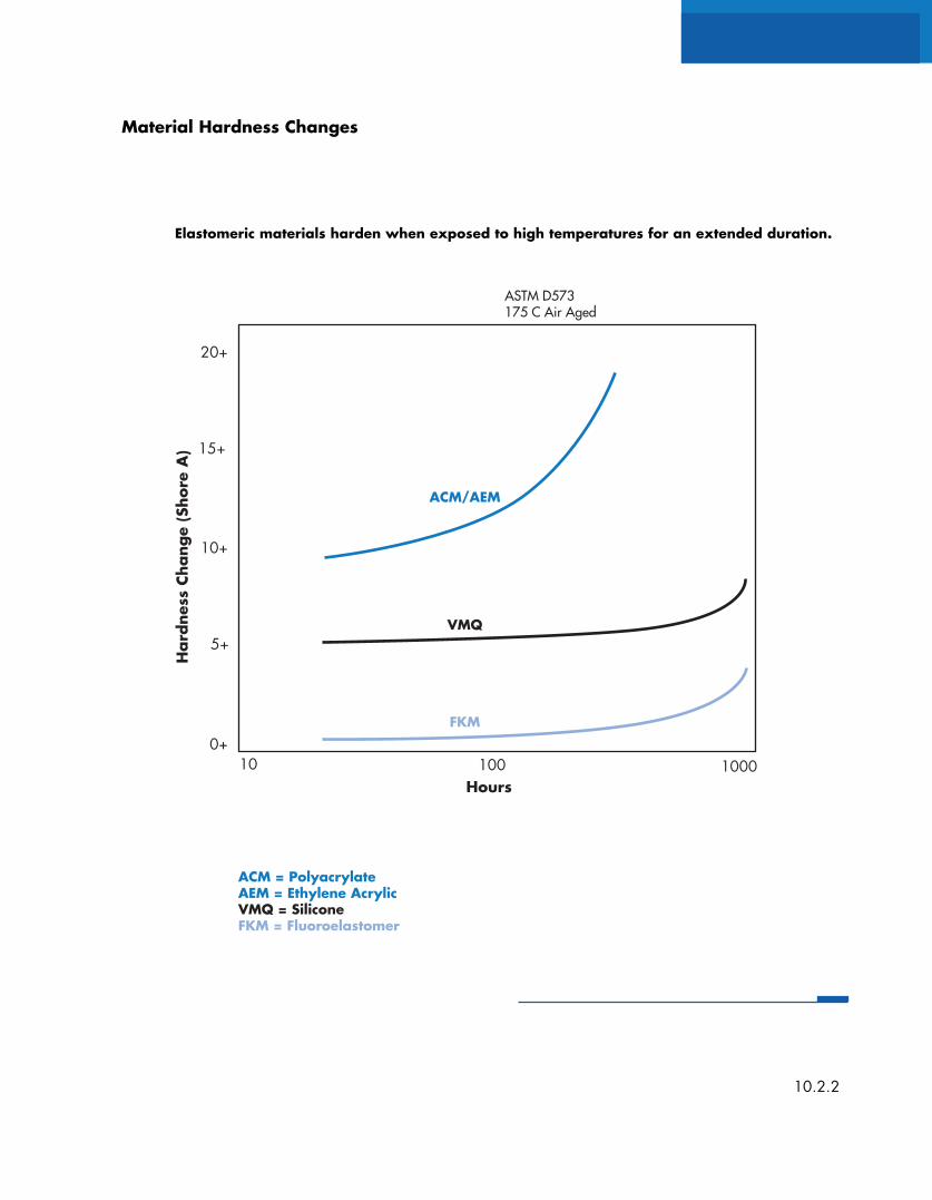
Elastomeric materials harden when exposed to high temperatures for an extended duration.
Material Hardness Changes
10.2.2
Hard
ness
Cha
nge
(Sho
re A
)
ASTM D573175 C Air Aged
ACM/AEM
VMQ
FKM
20+
10+
15+
5+
0+10 100 1000
Hours
ACM = PolyacrylateAEM = Ethylene AcrylicVMQ = SiliconeFKM = Fluoroelastomer
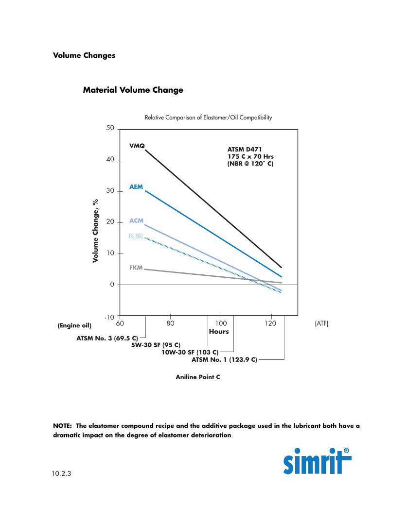
Material Volume Change
NOTE: The elastomer compound recipe and the additive package used in the lubricant both have adramatic impact on the degree of elastomer deterioration.
Volume Changes
10.2.3
Vol
ume
Chang
e, %
Relative Comparison of Elastomer/Oil Compatibility
ACM
VMQ
NBR
50
30
40
20
-1060 100 120
Hours
Aniline Point C
10
0
AEM
FKM
80 (ATF)
ATSM No. 1 (123.9 C)
ATSM D471175 C x 70 Hrs(NBR @ 120˚ C)
5W-30 SF (95 C)10W-30 SF (103 C)
ATSM No. 3 (69.5 C)
(Engine oil)
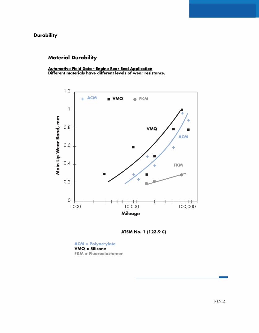
Material Durability
Automotive Field Data - Engine Rear Seal ApplicationDifferent materials have different levels of wear resistance.
Durability
10.2.4
Main
Lip
Wea
r Band
, m
m
ACM VMQ
1.2
0.8
1
0.6
01,000 10,000 100,000
Mileage
ATSM No. 1 (123.9 C)
0.4
0.2
FKM
ACM
VMQ
FKM
+
++
+
+
++
+
ACM = PolyacrylateVMQ = SiliconeFKM = Fluoroelastomer
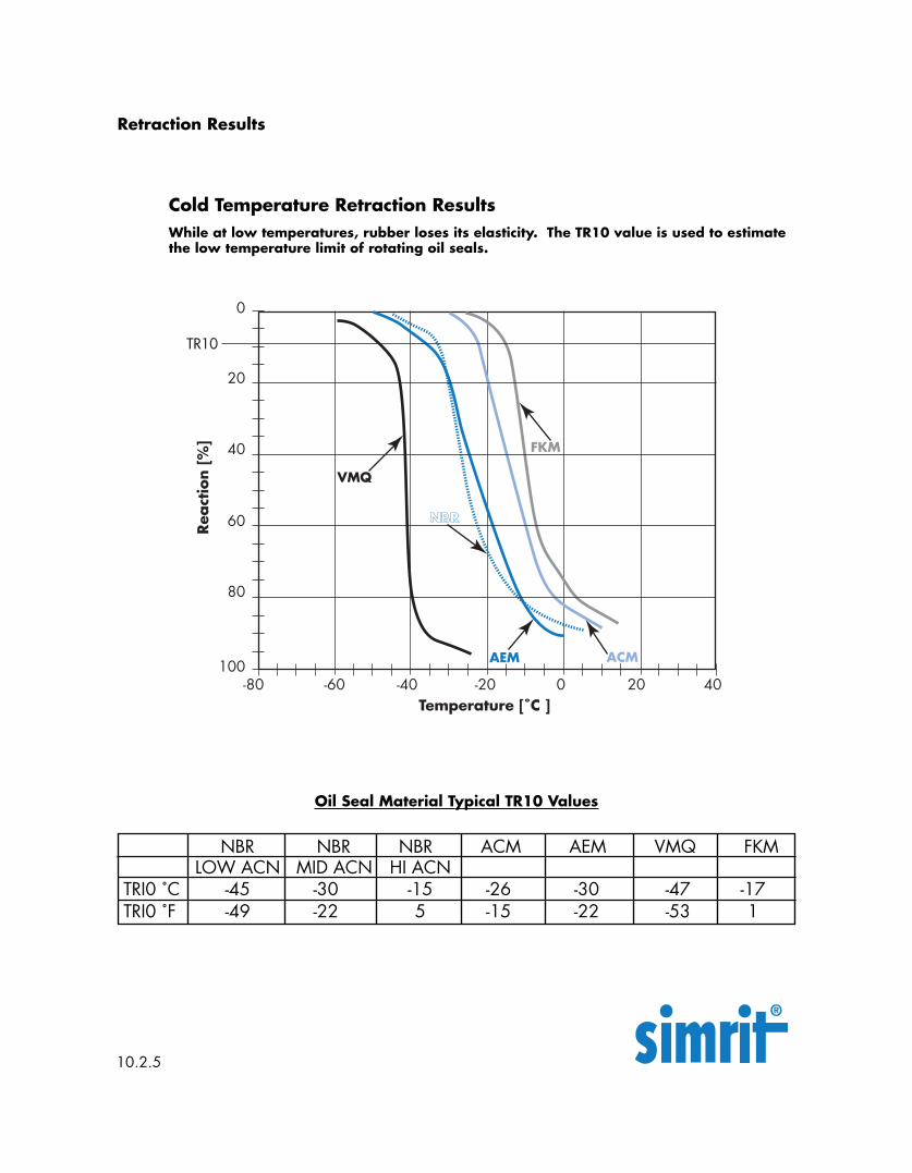
While at low temperatures, rubber loses its elasticity. The TR10 value is used to estimatethe low temperature limit of rotating oil seals.
Oil Seal Material Typical TR10 Values
Cold Temperature Retraction Results
Retraction Results
10.2.5
NBR NBR NBR ACM AEM VMQ FKMLOW ACN MID ACN HI ACN
TRI0 ˚C -45 -30 -15 -26 -30 -47 -17TRI0 ˚F -49 -22 5 -15 -22 -53 1
Rea
ctio
n [%
]
0
40
20
60
100-80 -40 20
Temperature [˚C ]
80
FKM
ACM
VMQ
NBR
AEM
TR10
-20 0 40-60
10.3
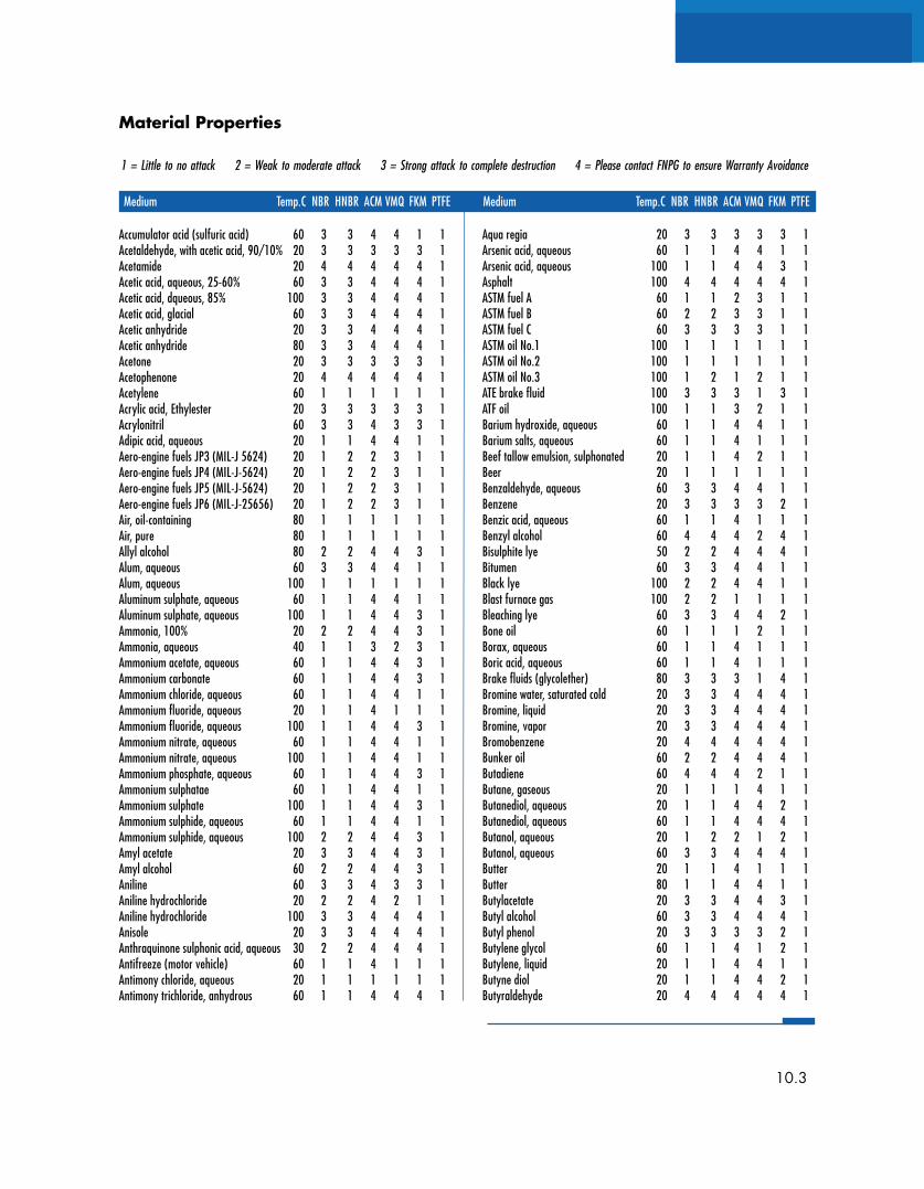
Material Properties
1 = Little to no attack 2 = Weak to moderate attack 3 = Strong attack to complete destruction 4 = Please contact FNPG to ensure Warranty Avoidance
Medium Temp.C NBR HNBR ACM VMQ FKM PTFE Medium Temp.C NBR HNBR ACM VMQ FKM PTFE
Accumulator acid (sulfuric acid) 60 3 3 4 4 1 1Acetaldehyde, with acetic acid, 90/10% 20 3 3 3 3 3 1Acetamide 20 4 4 4 4 4 1Acetic acid, aqueous, 25-60% 60 3 3 4 4 4 1Acetic acid, dqueous, 85% 100 3 3 4 4 4 1Acetic acid, glacial 60 3 3 4 4 4 1Acetic anhydride 20 3 3 4 4 4 1Acetic anhydride 80 3 3 4 4 4 1Acetone 20 3 3 3 3 3 1Acetophenone 20 4 4 4 4 4 1Acetylene 60 1 1 1 1 1 1Acrylic acid, Ethylester 20 3 3 3 3 3 1Acrylonitril 60 3 3 4 3 3 1Adipic acid, aqueous 20 1 1 4 4 1 1Aero-engine fuels JP3 (MIL-J 5624) 20 1 2 2 3 1 1Aero-engine fuels JP4 (MIL-J-5624) 20 1 2 2 3 1 1Aero-engine fuels JP5 (MIL-J-5624) 20 1 2 2 3 1 1Aero-engine fuels JP6 (MIL-J-25656) 20 1 2 2 3 1 1Air, oil-containing 80 1 1 1 1 1 1Air, pure 80 1 1 1 1 1 1Allyl alcohol 80 2 2 4 4 3 1Alum, aqueous 60 3 3 4 4 1 1Alum, aqueous 100 1 1 1 1 1 1Aluminum sulphate, aqueous 60 1 1 4 4 1 1Aluminum sulphate, aqueous 100 1 1 4 4 3 1Ammonia, 100% 20 2 2 4 4 3 1Ammonia, aqueous 40 1 1 3 2 3 1Ammonium acetate, aqueous 60 1 1 4 4 3 1Ammonium carbonate 60 1 1 4 4 3 1Ammonium chloride, aqueous 60 1 1 4 4 1 1Ammonium fluoride, aqueous 20 1 1 4 1 1 1Ammonium fluoride, aqueous 100 1 1 4 4 3 1Ammonium nitrate, aqueous 60 1 1 4 4 1 1Ammonium nitrate, aqueous 100 1 1 4 4 1 1Ammonium phosphate, aqueous 60 1 1 4 4 3 1Ammonium sulphatae 60 1 1 4 4 1 1Ammonium sulphate 100 1 1 4 4 3 1Ammonium sulphide, aqueous 60 1 1 4 4 1 1Ammonium sulphide, aqueous 100 2 2 4 4 3 1Amyl acetate 20 3 3 4 4 3 1Amyl alcohol 60 2 2 4 4 3 1Aniline 60 3 3 4 3 3 1Aniline hydrochloride 20 2 2 4 2 1 1Aniline hydrochloride 100 3 3 4 4 4 1Anisole 20 3 3 4 4 4 1Anthraquinone sulphonic acid, aqueous 30 2 2 4 4 4 1Antifreeze (motor vehicle) 60 1 1 4 1 1 1Antimony chloride, aqueous 20 1 1 1 1 1 1Antimony trichloride, anhydrous 60 1 1 4 4 4 1
Aqua regia 20 3 3 3 3 3 1Arsenic acid, aqueous 60 1 1 4 4 1 1Arsenic acid, aqueous 100 1 1 4 4 3 1Asphalt 100 4 4 4 4 4 1ASTM fuel A 60 1 1 2 3 1 1ASTM fuel B 60 2 2 3 3 1 1ASTM fuel C 60 3 3 3 3 1 1ASTM oil No.1 100 1 1 1 1 1 1ASTM oil No.2 100 1 1 1 1 1 1ASTM oil No.3 100 1 2 1 2 1 1ATE brake fluid 100 3 3 3 1 3 1ATF oil 100 1 1 3 2 1 1Barium hydroxide, aqueous 60 1 1 4 4 1 1Barium salts, aqueous 60 1 1 4 1 1 1Beef tallow emulsion, sulphonated 20 1 1 4 2 1 1Beer 20 1 1 1 1 1 1Benzaldehyde, aqueous 60 3 3 4 4 1 1Benzene 20 3 3 3 3 2 1Benzic acid, aqueous 60 1 1 4 1 1 1Benzyl alcohol 60 4 4 4 2 4 1Bisulphite lye 50 2 2 4 4 4 1Bitumen 60 3 3 4 4 1 1Black lye 100 2 2 4 4 1 1Blast furnace gas 100 2 2 1 1 1 1Bleaching lye 60 3 3 4 4 2 1Bone oil 60 1 1 1 2 1 1Borax, aqueous 60 1 1 4 1 1 1Boric acid, aqueous 60 1 1 4 1 1 1Brake fluids (glycolether) 80 3 3 3 1 4 1Bromine water, saturated cold 20 3 3 4 4 4 1Bromine, liquid 20 3 3 4 4 4 1Bromine, vapor 20 3 3 4 4 4 1Bromobenzene 20 4 4 4 4 4 1Bunker oil 60 2 2 4 4 4 1Butadiene 60 4 4 4 2 1 1Butane, gaseous 20 1 1 1 4 1 1Butanediol, aqueous 20 1 1 4 4 2 1Butanediol, aqueous 60 1 1 4 4 4 1Butanol, aqueous 20 1 2 2 1 2 1Butanol, aqueous 60 3 3 4 4 4 1Butter 20 1 1 4 1 1 1Butter 80 1 1 4 4 1 1Butylacetate 20 3 3 4 4 3 1Butyl alcohol 60 3 3 4 4 4 1Butyl phenol 20 3 3 3 3 2 1Butylene glycol 60 1 1 4 1 2 1Butylene, liquid 20 1 1 4 4 1 1Butyne diol 20 1 1 4 4 2 1Butyraldehyde 20 4 4 4 4 4 1
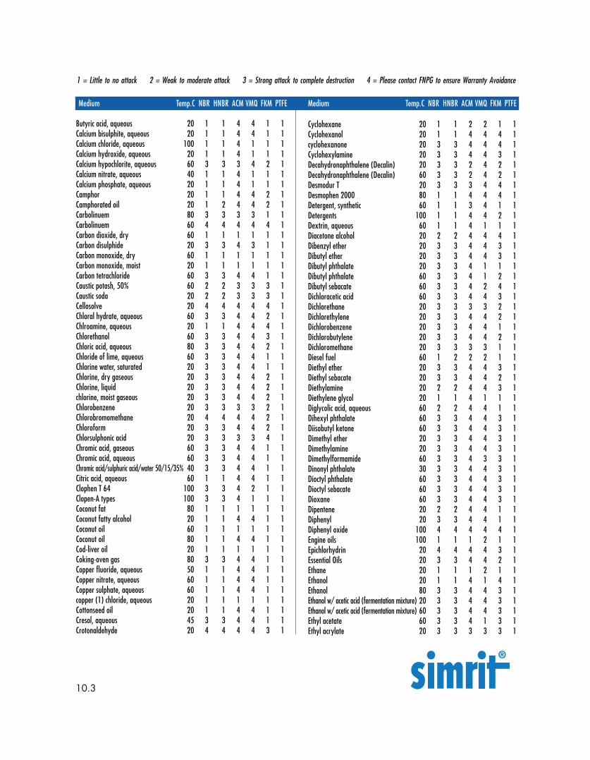
1 = Little to no attack 2 = Weak to moderate attack 3 = Strong attack to complete destruction 4 = Please contact FNPG to ensure Warranty Avoidance
Medium Temp.C NBR HNBR ACM VMQ FKM PTFE Medium Temp.C NBR HNBR ACM VMQ FKM PTFE
10.3
Butyric acid, aqueous 20 1 1 4 4 1 1Calcium bisulphite, aqueous 20 1 1 4 4 1 1Calcium chloride, aqueous 100 1 1 4 1 1 1Calcium hydroxide, aqueous 20 1 1 4 1 1 1Calcium hypochlorite, aqueous 60 3 3 3 4 2 1Calcium nitrate, aqueous 40 1 1 4 1 1 1Calcium phosphate, aqueous 20 1 1 4 1 1 1Camphor 20 1 1 4 4 2 1Camphorated oil 20 1 2 4 4 2 1Carbolinuem 80 3 3 3 3 1 1Carbolinuem 60 4 4 4 4 4 1Carbon dioxide, dry 60 1 1 1 1 1 1Carbon disulphide 20 3 3 4 3 1 1Carbon monoxide, dry 60 1 1 1 1 1 1Carbon monoxide, moist 20 1 1 1 1 1 1Carbon tetrachloride 60 3 3 4 4 1 1Caustic potash, 50% 60 2 2 3 3 3 1Caustic soda 20 2 2 3 3 3 1Cellosolve 20 4 4 4 4 4 1Chloral hydrate, aqueous 60 3 3 4 4 2 1Chlroamine, aqueous 20 1 1 4 4 4 1Chlorethanol 60 3 3 4 4 3 1Chloric acid, aqueous 80 3 3 4 4 2 1Chloride of lime, aqueous 60 3 3 4 4 1 1Chlorine water, saturated 20 3 3 4 4 1 1Chlorine, dry gaseous 20 3 3 4 4 2 1Chlorine, liquid 20 3 3 4 4 2 1chlorine, moist gaseous 20 3 3 4 4 2 1Chlorobenzene 20 3 3 3 3 2 1Chlorobromomethane 20 4 4 4 4 2 1Chloroform 20 3 3 4 4 2 1Chlorsulphonic acid 20 3 3 3 3 4 1Chromic acid, gaseous 60 3 3 4 4 1 1Chromic acid, aqueous 60 3 3 4 4 1 1Chromic acid/sulphuric acid/water 50/15/35% 40 3 3 4 4 1 1Citric acid, aqueous 60 1 1 4 4 1 1Clophen T 64 100 3 3 4 2 1 1Clopen-A types 100 3 3 4 1 1 1Coconut fat 80 1 1 1 1 1 1Coconut fatty alcohol 20 1 1 4 4 1 1Coconut oil 60 1 1 1 1 1 1Coconut oil 80 1 1 4 4 1 1Cod-liver oil 20 1 1 1 1 1 1Coking-oven gas 80 3 3 4 4 1 1Copper fluoride, aqueous 50 1 1 4 4 1 1Copper nitrate, aqueous 60 1 1 4 4 1 1Copper sulphate, aqueous 60 1 1 4 4 1 1copper (1) chloride, aqueous 20 1 1 1 1 1 1Cottonseed oil 20 1 1 4 4 1 1Cresol, aqueous 45 3 3 4 4 1 1Crotonaldehyde 20 4 4 4 4 3 1
Cyclohexane 20 1 1 2 2 1 1Cyclohexanol 20 1 1 4 4 4 1cyclohexanone 20 3 3 4 4 4 1Cyclohexylamine 20 3 3 4 4 3 1Decahydronaphthalene (Decalin) 20 3 3 2 4 2 1Decahydronaphthalene (Decalin) 60 3 3 2 4 2 1Desmodur T 20 3 3 3 4 4 1Desmophen 2000 80 1 1 4 4 4 1Detergent, synthetic 60 1 1 3 4 1 1Detergents 100 1 1 4 4 2 1Dextrin, aqueous 60 1 1 4 1 1 1Diacetone alcohol 20 2 2 4 4 4 1Dibenzyl ether 20 3 3 4 4 3 1Dibutyl ether 20 3 3 4 4 3 1Dibutyl phthalate 20 3 3 4 1 1 1Dibutyl phthalate 60 3 3 4 1 2 1Dibutyl sebacate 60 3 3 4 2 4 1Dichloracetic acid 60 3 3 4 4 3 1Dichlorethane 20 3 3 3 3 2 1Dichlorethylene 20 3 3 4 4 2 1Dichlorobenzene 20 3 3 4 4 1 1Dichlorobutylene 20 3 3 4 4 2 1Dichloromethane 20 3 3 3 3 1 1Diesel fuel 60 1 2 2 2 1 1Diethyl ether 20 3 3 4 4 3 1Diethyl sebacate 20 3 3 4 4 2 1Diethylamine 20 2 2 4 4 3 1Diethylene glycol 20 1 1 4 1 1 1Diglycolic acid, aqueous 60 2 2 4 4 1 1Dihexyl phthalate 60 3 3 4 4 3 1Diisobutyl ketone 60 3 3 4 4 3 1Dimethyl ether 20 3 3 4 4 3 1Dimethylamine 20 3 3 4 4 3 1Dimethylformamide 60 3 3 4 3 3 1Dinonyl phthalate 30 3 3 4 4 3 1Dioctyl phthalate 60 3 3 4 4 3 1Dioctyl sebacate 60 3 3 4 4 3 1Dioxane 60 3 3 4 4 3 1Dipentene 20 2 2 4 4 1 1Diphenyl 20 3 3 4 4 1 1Diphenyl oxide 100 4 4 4 4 4 1Engine oils 100 1 1 1 2 1 1Epichlorhydrin 20 4 4 4 4 3 1Essential Oils 20 3 3 4 4 2 1Ethane 20 1 1 1 2 1 1Ethanol 20 1 1 4 1 4 1Ethanol 80 3 3 4 4 3 1Ethanol w/ acetic acid (fermentation mixture) 20 3 3 4 4 3 1Ethanol w/ acetic acid (fermentation mixture) 60 3 3 4 4 3 1Ethyl acetate 60 3 3 4 1 3 1Ethyl acrylate 20 3 3 3 3 3 1

1 = Little to no attack 2 = Weak to moderate attack 3 = Strong attack to complete destruction 4 = Please contact FNPG to ensure Warranty Avoidance
Medium Temp.C NBR HNBR ACM VMQ FKM PTFE Medium Temp.C NBR HNBR ACM VMQ FKM PTFE
10.3
Ethyl benzene 20 3 3 3 3 2 1Ethyl chloride 20 2 2 3 3 2 1Ethyl ether 20 3 3 3 3 3 1Ethylene chloride 20 2 2 3 3 2 1Ethylene diamine 60 3 3 3 3 3 1Ethylene glycol 100 1 1 4 2 1 1Ethylene trichloride 20 4 4 4 4 4 1Exhaust gasses,containing carbon dioxide 60 1 1 1 1 1 1Exhaust gases, containing carbon monoxide 60 1 1 1 1 1 1Exhaust gases, containing hydrogen chloride 60 2 2 4 4 1 1Exhaust gases,containing hydrogen fluoride, traces60 1 1 4 4 1 1Exhaust gases, containing nitrous gases, traces 60 4 4 3 3 1 1Exhaust gases, containing nitrous gases, traces 80 4 4 3 3 1 1Exhaust gases, containing sulphur dioxide 60 2 2 4 4 1 1Exhaust gases, containing sulphuric acid 60 2 2 4 4 1 1Exhaust gases, containing sulphuric acid 80 3 3 4 4 1 1Fats; mineral, animal or vegetable 80 1 1 1 1 1 1Fatty acids 100 2 2 4 4 1 1Fatty alcohol 20 1 1 1 1 1 1Fertilizer salt, aqueous 60 1 1 4 1 1 1Fish oil 20 1 1 1 1 1 1Fluorine, dry 60 3 3 4 4 4 1Fluorobenzene 20 3 3 3 3 2 1Fluorocarbon oils 100 4 4 4 1 4 1Fluorosilicic acid 100 4 4 4 4 4 1Fluorosilicic acid, aqueous 60 1 1 4 4 1 1Formaldehyde, aqueous 60 2 2 3 4 4 1Formamide 60 3 3 4 4 2 1Formic acid, aqueous 60 3 3 4 4 4 1Freon according…Fruit juice 100 2 2 4 1 1 1Furane 20 4 4 4 4 3 1Furfural 20 3 3 4 4 4 1Furfuryl alcohol 20 4 4 4 4 4 1Furnace gas, dry 60 3 3 4 1 1 1Gas liquor 40 1 1 3 3 1 1Gas oil 80 1 1 1 2 1 1Gasohol 20 3 3 3 3 4 1Gelatine, aqueous 40 1 1 2 1 1 1Glaubers salt, aqueous (sodium sulphate) 20 1 1 2 4 1 1Glucose, aqueous 80 1 1 4 1 1 1Glue 20 1 1 1 1 1 1Glycerol chlorhydrin 60 3 3 4 4 4 1Glycerol, aqueous 100 1 1 4 1 1 1Glycine, aqueous, 10% 40 2 2 4 4 1 1Glycol, aqueous 100 1 1 4 2 2 1Glycolic acid, aqueous, 37% 20 1 1 4 1 1 1Grape sugar, aqueous 80 1 1 4 1 1 1Heating oil, mineral-oil based 60 1 1 1 2 1 1Henkel P3 solution 100 1 1 4 4 4 1Heptane 60 1 1 1 3 1 1Hexachlorobutadiene 20 3 3 4 4 1 1Hexachlorobutadiene 20 4 4 4 4 1 1Hhexaldehyde 20 3 3 4 4 4 1
Hexane 60 1 1 1 3 1 1Hexane triol 20 1 1 4 1 1 1Hexene 20 2 2 1 4 1 1Hydraulic fluids, hydraulic oils 80 1 1 1 2 1 1Hydraulic fluids, oil-in-water emulsions HFA 55 1 1 4 4 1 1Hydraulic fluids, phosphoric acid ester HFD 80 3 3 3 3 4 1Hydraulic fluids, polyglycol-water emulsions 60 1 1 4 1 1 1Hydraulic fluids, water-in oil emoulsions HFB 60 4 4 4 4 1 1Hydrazine hydrate 20 2 2 4 4 4 1Hydrobromic acid, aqueous 60 2 2 4 4 4 1Hydrochloric acid, concentrated 80 3 3 4 4 1 1Hydrochloric acid, concentrated 20 3 3 4 4 1 1Hydrochloric acid, dilute 20 1 2 4 4 1 1Hydrofluoric acid, concentrated 20 4 4 4 4 4 1Hydrogen 20 1 1 1 1 1 1Hydrogen chloride gas 60 3 34 4 1 1Hydrogen peroxide, aqueous 20 3 3 4 2 1 1Hydrogen sulphide, aqueous 60 2 2 4 4 1 1Hydrogen sulphide, dry 60 2 2 4 4 1 1Hydroquinone, acqueous 20 1 1 2 4 1 1Hydrosulphite, aqueous 40 2 2 4 4 4 1Hydroxylamine sulphate, aqueous 35 1 1 4 1 4 1Ink 20 1 2 1 1 2 1Iodine, tincture 20 1 1 4 2 1 1Iodoform 20 4 4 4 4 1 1Iron (III) chloride, aqueous 40 1 1 4 4 1 1Isobutanol 20 2 2 3 1 1 1Isoctane 20 1 1 1 2 1 1Isophorone 20 4 4 4 4 4 1Isopropanol 60 2 2 3 1 2 1Isopropyl acetate 80 3 3 3 3 3 1Isopropyl chloride 20 3 3 3 3 1 1Isopropyl ether 60 3 3 3 3 3 1Kerossene 20 1 2 1 2 1 1Lactam 80 3 3 4 4 3 1Lactic acid, aqueous 40 1 1 4 4 1 1Lanolin (wool fat) 60 1 1 1 1 1 1Laughing gas (nitrous oxide) 20 1 1 1 1 1 1Lauryl alcohol 20 1 1 4 4 1 1Lavender oil 20 2 2 2 4 1 1Lead acetate, aqueous 60 1 2 4 4 1 1Lead acetate, aqueous 100 1 2 4 4 3 1Lead nitrate, aqueous 20 1 1 4 4 1 1Lemon juice, undiluted 20 1 1 4 1 4 1Linoleic acid 20 2 2 4 2 2 1Linseed oil 60 1 1 1 1 1 1Liquers 20 1 1 1 1 1 1Lithium bromide, aqueous 1 1 4 1 1 1 1Lithium chloride, aqueous 20 1 1 1 1 1 1Machine oil, mineral 80 1 1 1 2 1 1Magnesium chloride, aqueous 100 1 1 3 4 1 1Magnesium sulphate, aqueous 100 1 1 3 4 1 1Maize oil (corn oil) 60 1 1 4 4 1 1Maleic acid, aqueous 100 1 1 4 4 1 1
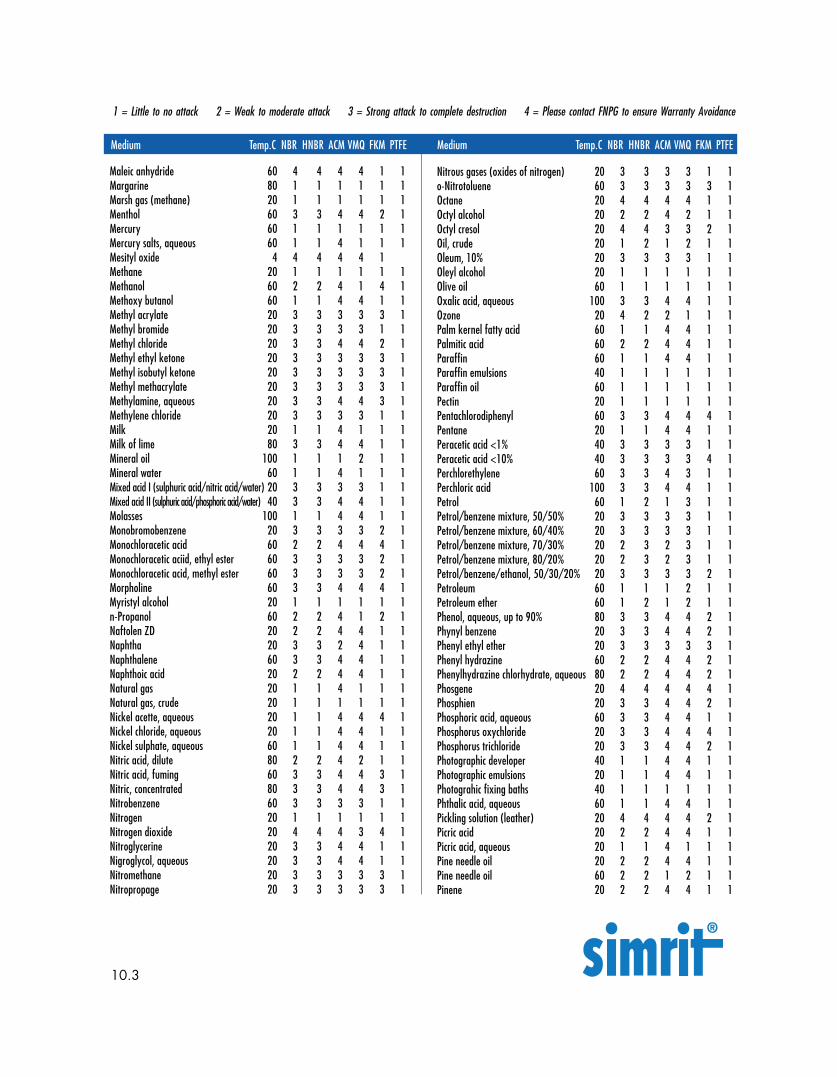
1 = Little to no attack 2 = Weak to moderate attack 3 = Strong attack to complete destruction 4 = Please contact FNPG to ensure Warranty Avoidance
Medium Temp.C NBR HNBR ACM VMQ FPM PTFEMedium Temp.C NBR HNBR ACM VMQ FKM PTFE Medium Temp.C NBR HNBR ACM VMQ FKM PTFE
10.3
Maleic anhydride 60 4 4 4 4 1 1Margarine 80 1 1 1 1 1 1Marsh gas (methane) 20 1 1 1 1 1 1Menthol 60 3 3 4 4 2 1Mercury 60 1 1 1 1 1 1Mercury salts, aqueous 60 1 1 4 1 1 1Mesityl oxide 4 4 4 4 4 1Methane 20 1 1 1 1 1 1Methanol 60 2 2 4 1 4 1Methoxy butanol 60 1 1 4 4 1 1Methyl acrylate 20 3 3 3 3 3 1Methyl bromide 20 3 3 3 3 1 1Methyl chloride 20 3 3 4 4 2 1Methyl ethyl ketone 20 3 3 3 3 3 1Methyl isobutyl ketone 20 3 3 3 3 3 1Methyl methacrylate 20 3 3 3 3 3 1Methylamine, aqueous 20 3 3 4 4 3 1Methylene chloride 20 3 3 3 3 1 1Milk 20 1 1 4 1 1 1Milk of lime 80 3 3 4 4 1 1Mineral oil 100 1 1 1 2 1 1Mineral water 60 1 1 4 1 1 1Mixed acid I (sulphuric acid/nitric acid/water) 20 3 3 3 3 1 1Mixed acid II (sulphuric acid/phosphoric acid/water) 40 3 3 4 4 1 1Molasses 100 1 1 4 4 1 1Monobromobenzene 20 3 3 3 3 2 1Monochloracetic acid 60 2 2 4 4 4 1Monochloracetic aciid, ethyl ester 60 3 3 3 3 2 1Monochloracetic acid, methyl ester 60 3 3 3 3 2 1Morpholine 60 3 3 4 4 4 1Myristyl alcohol 20 1 1 1 1 1 1n-Propanol 60 2 2 4 1 2 1Naftolen ZD 20 2 2 4 4 1 1Naphtha 20 3 3 2 4 1 1Naphthalene 60 3 3 4 4 1 1Naphthoic acid 20 2 2 4 4 1 1Natural gas 20 1 1 4 1 1 1Natural gas, crude 20 1 1 1 1 1 1Nickel acette, aqueous 20 1 1 4 4 4 1Nickel chloride, aqueous 20 1 1 4 4 1 1Nickel sulphate, aqueous 60 1 1 4 4 1 1Nitric acid, dilute 80 2 2 4 2 1 1Nitric acid, fuming 60 3 3 4 4 3 1Nitric, concentrated 80 3 3 4 4 3 1Nitrobenzene 60 3 3 3 3 1 1Nitrogen 20 1 1 1 1 1 1Nitrogen dioxide 20 4 4 4 3 4 1Nitroglycerine 20 3 3 4 4 1 1Nigroglycol, aqueous 20 3 3 4 4 1 1Nitromethane 20 3 3 3 3 3 1Nitropropage 20 3 3 3 3 3 1
Nitrous gases (oxides of nitrogen) 20 3 3 3 3 1 1o-Nitrotoluene 60 3 3 3 3 3 1Octane 20 4 4 4 4 1 1Octyl alcohol 20 2 2 4 2 1 1Octyl cresol 20 4 4 3 3 2 1Oil, crude 20 1 2 1 2 1 1Oleum, 10% 20 3 3 3 3 1 1Oleyl alcohol 20 1 1 1 1 1 1Olive oil 60 1 1 1 1 1 1Oxalic acid, aqueous 100 3 3 4 4 1 1Ozone 20 4 2 2 1 1 1Palm kernel fatty acid 60 1 1 4 4 1 1Palmitic acid 60 2 2 4 4 1 1Paraffin 60 1 1 4 4 1 1Paraffin emulsions 40 1 1 1 1 1 1Paraffin oil 60 1 1 1 1 1 1Pectin 20 1 1 1 1 1 1Pentachlorodiphenyl 60 3 3 4 4 4 1Pentane 20 1 1 4 4 1 1Peracetic acid <1% 40 3 3 3 3 1 1Peracetic acid <10% 40 3 3 3 3 4 1Perchlorethylene 60 3 3 4 3 1 1Perchloric acid 100 3 3 4 4 1 1Petrol 60 1 2 1 3 1 1Petrol/benzene mixture, 50/50% 20 3 3 3 3 1 1Petrol/benzene mixture, 60/40% 20 3 3 3 3 1 1Petrol/benzene mixture, 70/30% 20 2 3 2 3 1 1Petrol/benzene mixture, 80/20% 20 2 3 2 3 1 1Petrol/benzene/ethanol, 50/30/20% 20 3 3 3 3 2 1Petroleum 60 1 1 1 2 1 1Petroleum ether 60 1 2 1 2 1 1Phenol, aqueous, up to 90% 80 3 3 4 4 2 1Phynyl benzene 20 3 3 4 4 2 1Phenyl ethyl ether 20 3 3 3 3 3 1Phenyl hydrazine 60 2 2 4 4 2 1Phenylhydrazine chlorhydrate, aqueous 80 2 2 4 4 2 1Phosgene 20 4 4 4 4 4 1Phosphien 20 3 3 4 4 2 1Phosphoric acid, aqueous 60 3 3 4 4 1 1Phosphorus oxychloride 20 3 3 4 4 4 1Phosphorus trichloride 20 3 3 4 4 2 1Photographic developer 40 1 1 4 4 1 1Photographic emulsions 20 1 1 4 4 1 1Photograhic fixing baths 40 1 1 1 1 1 1Phthalic acid, aqueous 60 1 1 4 4 1 1Pickling solution (leather) 20 4 4 4 4 2 1Picric acid 20 2 2 4 4 1 1Picric acid, aqueous 20 1 1 4 1 1 1Pine needle oil 20 2 2 4 4 1 1Pine needle oil 60 2 2 1 2 1 1Pinene 20 2 2 4 4 1 1
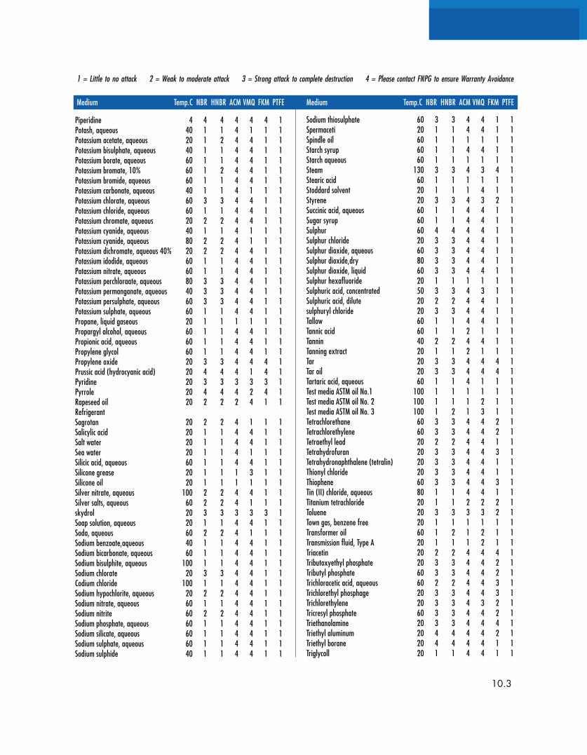
1 = Little to no attack 2 = Weak to moderate attack 3 = Strong attack to complete destruction 4 = Please contact FNPG to ensure Warranty Avoidance
Medium Temp.C NBR HNBR ACM VMQ FKM PTFE Medium Temp.C NBR HNBR ACM VMQ FKM PTFE
10.3
Piperidine 4 4 4 4 4 4 1Potash, aqueous 40 1 1 4 1 1 1Potassium acetate, aqueous 20 1 2 4 4 1 1Potassium bisulphate, aqueous 40 1 1 4 4 1 1Potassium borate, aqueous 60 1 1 4 4 1 1Potassium bromate, 10% 60 1 2 4 4 1 1Potassium bromide, aqueous 60 1 1 4 4 1 1Potassium carbonate, aqueous 40 1 1 4 1 1 1Potassium chlorate, aqueous 60 3 3 4 4 1 1Potassium chloride, aqueous 60 1 1 4 4 1 1Potassium chromate, aqueous 20 2 2 4 4 1 1Potassium cyanide, aqueous 40 1 1 4 1 1 1Potassium cyanide, aqueous 80 2 2 4 1 1 1Potassium dichromate, aqueous 40% 20 2 2 4 4 1 1Potassium idodide, aqueous 60 1 1 4 4 1 1Potassium nitrate, aqueous 60 1 1 4 4 1 1Potassium perchloraate, aqueous 80 3 3 4 4 1 1Potassium permanganate, aqueous 40 3 3 4 4 1 1Potassium persulphate, aqueous 60 3 3 4 4 1 1Potassium sulphate, aqueous 60 1 1 4 4 1 1Propane, liquid gaseous 20 1 1 1 1 1 1Propargyl alcohol, aqueous 60 1 1 4 4 1 1Propionic acid, aqueous 60 1 1 4 4 1 1Propylene glycol 60 1 1 4 4 1 1Propylene oxide 20 3 3 4 4 4 1Prussic acid (hydrocyanic acid) 20 4 4 4 1 4 1Pyridine 20 3 3 3 3 3 1Pyrrole 20 4 4 4 2 4 1Rapeseed oil 20 2 2 2 4 1 1RefrigerantSagrotan 20 2 2 4 1 1 1Salicylic acid 20 1 1 4 4 1 1Salt water 20 1 1 4 4 1 1Sea water 20 1 1 4 1 1 1Silicic acid, aqueous 60 1 1 4 4 1 1Silicone grease 20 1 1 1 3 1 1Silicone oil 20 1 1 1 1 1 1Silver nitrate, aqueous 100 2 2 4 4 1 1Silver salts, aqueous 60 2 2 4 1 1 1skydrol 20 3 3 3 3 3 1Soap solution, aqueous 20 1 1 4 4 1 1Soda, aqueous 60 2 2 4 1 1 1Sodium benzoate,aqueous 40 1 1 4 4 1 1Sodium bicarbonate, aqueous 60 1 1 4 4 1 1Sodium bisulphite, aqueous 100 1 1 4 4 1 1Sodium chlorate 20 3 3 4 4 1 1Codium chloride 100 1 1 4 4 1 1Sodium hypochlorite, aqueous 20 2 2 4 4 1 1Sodium nitrate, aqueous 60 1 1 4 4 1 1Sodium nitrite 60 2 2 4 4 1 1Sodium phosphate, aqueous 60 1 1 4 4 1 1Sodium silicate, aqueous 60 1 1 4 4 1 1Sodium sulphate, aqueous 60 1 1 4 4 1 1Sodium sulphide 40 1 1 4 4 1 1
Sodium thiosulphate 60 3 3 4 4 1 1Spermaceti 20 1 1 4 4 1 1Spindle oil 60 1 1 1 1 1 1Starch syrup 60 1 1 4 4 1 1Starch aqueous 60 1 1 1 1 1 1Steam 130 3 3 4 3 4 1Stearic acid 60 1 1 1 1 1 1Stoddard solvent 20 1 1 1 4 1 1Styrene 20 3 3 4 3 2 1Succinic acid, aqueous 60 1 1 4 4 1 1Sugar syrup 60 1 1 4 4 1 1Sulphur 60 4 4 4 4 1 1Sulphur chloride 20 3 3 4 4 1 1Sulphur dioxide, aqueous 60 3 3 4 4 1 1Sulphur dioxide,dry 80 3 3 4 4 1 1Sulphur dioxide, liquid 60 3 3 4 4 1 1Sulphur hexafluoride 20 1 1 1 1 1 1Sulphuric acid, concentrated 50 3 3 4 3 1 1Sulphuric acid, dilute 20 2 2 4 4 1 1sulphuryl chloride 20 3 3 4 4 1 1Tallow 60 1 1 4 4 1 1Tannic acid 60 1 1 2 1 1 1Tannin 40 2 2 4 4 1 1Tanning extract 20 1 1 2 1 1 1Tar 20 3 3 4 4 4 1Tar oil 20 3 3 4 4 4 1Tartaric acid, aqueous 60 1 1 4 1 1 1Test media ASTM oil No.1 100 1 1 1 1 1 1Test media ASTM oil No. 2 100 1 1 1 2 1 1Test media ASTM oil No. 3 100 1 2 1 3 1 1Tetrachlorethane 60 3 3 4 4 2 1Tetrachlorethylene 60 3 3 4 4 2 1Tetraethyl lead 20 2 2 4 4 1 1Tetrahydrofuran 20 3 3 4 4 3 1Tetrahydronaphthalene (tetralin) 20 3 3 4 4 1 1Thionyl chloride 20 3 3 4 4 1 1Thiophene 60 3 3 4 4 3 1Tin (II) chloride, aqueous 80 1 1 4 4 1 1Titanium tetrachloride 20 1 1 2 2 2 1Toluene 20 3 3 3 3 2 1Town gas, benzene free 20 1 1 1 1 1 1Transformer oil 60 1 2 1 2 1 1Transmission fluid, Type A 20 1 1 1 2 1 1Triacetin 20 2 2 4 4 4 1Tributoxyethyl phosphate 20 3 3 4 4 2 1Tributyl phosphate 60 3 3 4 4 2 1Trichloracetic acid, aqueous 60 2 2 4 4 3 1Trichlorethyl phosphage 20 3 3 4 4 3 1Trichlorethylene 20 3 3 4 3 2 1Tricresyl phosphate 60 3 3 4 4 2 1Triethanolamine 20 3 3 4 4 4 1Triethyl aluminum 20 4 4 4 4 2 1Triethyl borane 20 4 4 4 4 1 1Triglycoll 20 1 1 4 4 1 1
1 = Little to no attack 2 = Weak to moderate attack 3 = Strong attack to complete destruction 4 = Please contact FNPG to ensure Warranty Avoidance
Medium Temp.C NBR HNBR ACM VMQ FKM PTFE Medium Temp.C NBR HNBR ACM VMQ FKM PTFE
11.0.5
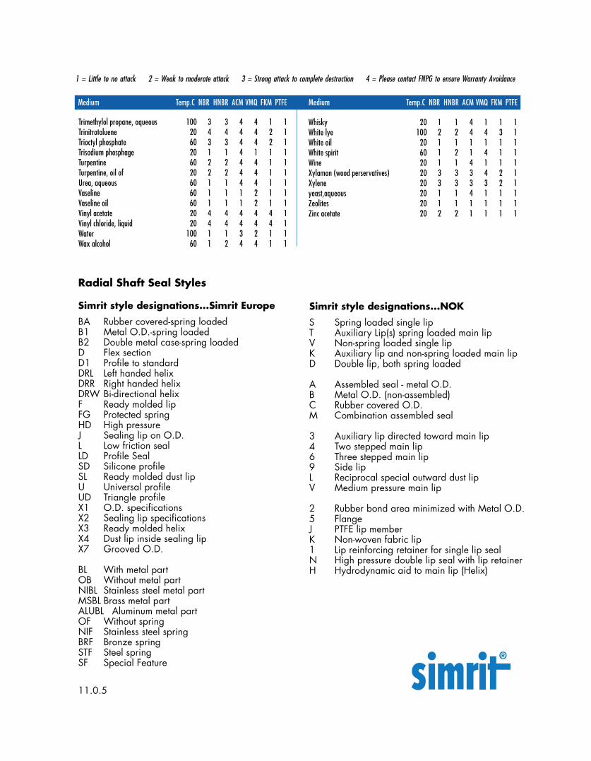
Trimethylol propane, aqueous 100 3 3 4 4 1 1Trinitrotoluene 20 4 4 4 4 2 1Trioctyl phosphate 60 3 3 4 4 2 1Trisodium phosphage 20 1 1 4 1 1 1Turpentine 60 2 2 4 4 1 1Turpentine, oil of 20 2 2 4 4 1 1Urea, aqueous 60 1 1 4 4 1 1Vaseline 60 1 1 1 2 1 1Vaseline oil 60 1 1 1 2 1 1Vinyl acetate 20 4 4 4 4 4 1Vinyl chloride, liquid 20 4 4 4 4 4 1Water 100 1 1 3 2 1 1Wax alcohol 60 1 2 4 4 1 1
Simrit style designations...Simrit Europe
BA Rubber covered-spring loadedB1 Metal O.D.-spring loadedB2 Double metal case-spring loadedD Flex sectionD1 Profile to standardDRL Left handed helixDRR Right handed helixDRW Bi-directional helixF Ready molded lipFG Protected springHD High pressureJ Sealing lip on O.D.L Low friction sealLD Profile SealSD Silicone profileSL Ready molded dust lipU Universal profileUD Triangle profileX1 O.D. specificationsX2 Sealing lip specificationsX3 Ready molded helixX4 Dust lip inside sealing lipX7 Grooved O.D.
BL With metal partOB Without metal partNIBL Stainless steel metal partMSBL Brass metal partALUBL Aluminum metal partOF Without springNIF Stainless steel springBRF Bronze springSTF Steel springSF Special Feature
Radial Shaft Seal Styles
Simrit style designations...NOK
S Spring loaded single lipT Auxiliary Lip(s) spring loaded main lipV Non-spring loaded single lipK Auxiliary lip and non-spring loaded main lipD Double lip, both spring loaded
A Assembled seal - metal O.D.B Metal O.D. (non-assembled)C Rubber covered O.D.M Combination assembled seal
3 Auxiliary lip directed toward main lip4 Two stepped main lip6 Three stepped main lip9 Side lipL Reciprocal special outward dust lipV Medium pressure main lip
2 Rubber bond area minimized with Metal O.D.5 FlangeJ PTFE lip memberK Non-woven fabric lip1 Lip reinforcing retainer for single lip sealN High pressure double lip seal with lip retainerH Hydrodynamic aid to main lip (Helix)
Whisky 20 1 1 4 1 1 1White lye 100 2 2 4 4 3 1White oil 20 1 1 1 1 1 1White spirit 60 1 2 1 4 1 1Wine 20 1 1 4 1 1 1Xylamon (wood perservatives) 20 3 3 3 4 2 1Xylene 20 3 3 3 3 2 1yeast,aqueous 20 1 1 4 1 1 1Zeolites 20 1 1 1 1 1 1Zinc acetate 20 2 2 1 1 1 1
12.0
Assembled spring – Inside Diameter:The inner diameter of the garter spring,with the ends securely joined.
Axial clearance: The gap between the toeface to the head section and the insidesurface of the inner case.
Circumferential surface roughness:Surface roughness of a shaft measured ina direction (plane) normal to thecenterline axis.
Cocked assembly: An installation in whichthe plane of the outside seal face is notperpendicular to the shaft axis.
Coil: One turn of the coiled wire garter spring.
Contact approach angle: Synonym:Angle, Outside lip
Contact line: The line of intersection betweenthe outside and inside lip surfaces of aradial shaft seal. In a cross-section view,this intersection is illustrated as a point.
Contact line height: The axial distance fromthe outside seal face to the lip contactline.
Contact width: The width of the lip contactarea of a radial shaft seal, measured inthe axial direction.
Crack: A sharp break or fissure in the sealingelement.
Cut: A deep discontinuity in the seal materialwhereby no material is removed.
Deformation: A stress induced change ofform or shape.
Dynamic Run-out: Twice the distance thecenter of the shaft is displaced from thecenter of rotation and expressed in TIR.That Run-out to which the seal lip issubjected due to the outside diameter ofthe shaft not rotating in a true circle.Synonym: Shaft Run-out
Elastomer: An elastic rubber like substance.
Extrusion: Permanent displacement of part ofa seal into a gap, under the action of fluidpressure.
Fluid side: The side of the seal which innormal use faces toward the fluid beingsealed.
Functional lip diameter: The apparentinner diameter of the seal when the sealcase is concentric with the outer diameterof the sizing mandrel in an air gage, lightbox, or similar inspection equipment.
Garter spring: A helically coiled wire withits’ ends connected to form a ring. It isused in tension for maintaining a radialsealing force between element of a radiallip seal and a shaft.
Heel: Synonym: Heel section
Heel section: The portion of a lip seal whichis attached to the seal case and boundedby the flex section and the outside face.
Helix contact width: The axial width of thatportion of the contact surface of a helixseal which is formed by the helical ribs. Itis equal to the total axial width of thecontact surface minus the width of thestatic lip.
Housing bore: A cylindrical surface whichmates with the outside diameter of theouter seal case.
Hydrodynamic seal: A dynamic sealingdevice which utilizes the viscous shearand inertia forces of the fluid; imparted bya helically grooved or ribbed seal lip, togenerate a pressure differential thatopposes fluid flow.
Inclusion: Foreign matter included in the sealmaterial.
Inner case: A rigid, cup-shaped component ofa seal assembly, which is placed insidethe outer seal case. It has one or more ofthe following functions: reinforcingmember, shield, spring retainer, lip-clamping device.
Glossary of Terms
12.0
Inside face: That surface of the inner casewhich faces, and is usally in contact with,the fluid being sealed.
Inside single lip angle: The angle betweenthe inside lip surface and the axis of theseal case.
Lip diameter: The inner diameter of the seallip, measured with the spring installed.
Lip force: The radial force exerted by anextension spring and/or lip of a seal on themating shaft. Lip force is expressed asforce per unit of shaft circumference.
Lip height: The axial distance from the outsideseal face to the toe face.
Lip ID to ID eccentricity: See: Radial WallVariance
Lip opening pressure: The pressure neces-sary for flowing air at 10000 cc/min.between the contact surface of a radial lipseal and shaft-size mandrel under thefollowing conditions: the seal case outerdiameter clamped to be concentric with themandrel and the pressurized air applied tothe outside lip surface.
Lip seal: An elastomeric seal which preventsleakage in dynamic and static applicationsby reason of controlled interference be-tween the seal lip and the mating surface.
Lubricant starvation: Lack of proper lubrica-tion at the seal interface which may causepremature wear and early failure.
Offset: The radial distance between the axis ofthe seal bore and axis of shaft rotation.
Oil seal: A seal designed primarily for theretention of oil.
Outer case: the outer thin-wall rigid structure ofthe lip seal assembly which contains theinner case, the primary seal ring, the springand the secondary seal.
Outside lip angle: The angle between theoutside lip and the axis of the seal case.
Plunge ground: The surface texture of shaftor wear sleeve produced by presenting thegrinding wheel perpendicular to therotating shaft without axial motion.
Primary lip: The normally flexible elastomericcomponent of a shaft seal assembly, whichrides against the rotating surface andaffects the seal.
Radial lip seal: A type of seal which featuresa flexible sealing member referred to as alip. The lip is usually an elastomericmaterial. It exerts radial sealing pressureon a mating shaft in order to retain fluidsand/or exclude foreign matter.
Radial load: The total force (load) acting onthe seal lip which tends to maintaincontact of the lip on the shaft. It is the sumof the forces developed from seal interfer-ence and the garter spring.
Radial wall variation: the differencebetween the minimum and the maximumradial wall dimensions when measuredaround 360 degrees, of the seal lip.
Rib: A long, narrow projection which isnormally triangular in cross-section andwhich is molded into the outside lipsurface of a helical seal. It is oriented atan angle to the shaft axis. One end of therib forms part of the seal-lip contactsurface.
Rough trim: A trimmed surface with irregulari-ties on the outside and inside lip surfacesin the immediate vicinity of the contact line
Roughness: Irregularities in shaft surfacetexture which result from the productionprocess. (See SAE J448a [June, 1963].)
Scratch: A shallow discontinuity in the sealmaterial whereby no material is removed.
Seal assembly: A group of parts, whichincludes sealing surfaces, provisions forinitial loading, and a secondary sealingmechanism which accommodates theradial movement necessary for installationand operation.
12.0
Seal case: A rigid member to which the seallip is attached.
Seal outer diameter: The external diameterof a lip-seal assembly.
Shaft eccentricity: The radial distance inwhich the geometric center of a shaft isdisplaced from the axis of shaft rotation.
Shaft lead: Spiral grooves on a shaft surfacecaused by relative axial movement ofgrinding wheel to shaft.
Shaft Run-out: See: Dynamic Run-out
Shaft surface finish: See: Shaft SurfaceTexture
Shaft surface texture: A term used todescribe the quality, appearance orcharacteristics of the shaft surface resultingfrom operations, such as grinding, polish-ing, burnishing, etc. (See SAE J448a[June, 1963]).
Slip stick: A friction related phenomena inwhich the sealing element tends to adhereand rotate with the shaft surface momen-tarily until the elastic characteristics of thesealing element overcome the adhesiveforce, causing the seal lip to lose connec-tion with the rotating shaft long enough toallow leakage. This cycle repeats itselfcontinuously and is normally associatedwith non-lubricated and boundary-lubri-cated conditions
Spiral trim: A trimmed surface which has aspiral pattern.
Spring groove: A depression formed in thehead section of the seal. It is generallysemicircular in form and serves to accom-modate and locate the garter spring.
Spring outside coil diameter: The outerdiameter of an individual helical coil of agarter spring.
Spring retaining lip: The portion of theprimary lip that restricts the axial move-ment of the extension spring from apredetermined position.
Trim: The removal of superfluous parts from amolded product, usually removal ofparting line flash or feed spews.
Trim cut: Damage to the elastomeric portion ofthe seal during trimming.
Trimming angle: The angle between thetrimmed face of a seal lip and the sealaxis.
Trimmed lip diameter: The lip diameter inthe free state (no spring) developed byknife trimming the molded portion of thesealing element to form the contact line.
Unbonded flash: Flash which does notadhere to the mating material.
Unirotational seal: A seal, designed forapplications having a single direction ofshaft rotation.
Unitized seal: A seal assembly in which allcomponents necessary for accomplishingthe complete sealing function are retainedin a single package.
Under-cure: A degree of cure less thandesired.
Volume swell: Increase in physical sizecaused by the swelling action of a liquid,generally expressed as a percent of theoriginal volume.
Wear sleeve: A replacement metal ringgenerally used in assemblies to eliminateexpensive shaft replacement caused bygrooving that may occur at the seal-shaftinterface.
Weepage: A minute amount of liquid leakageby a seal.
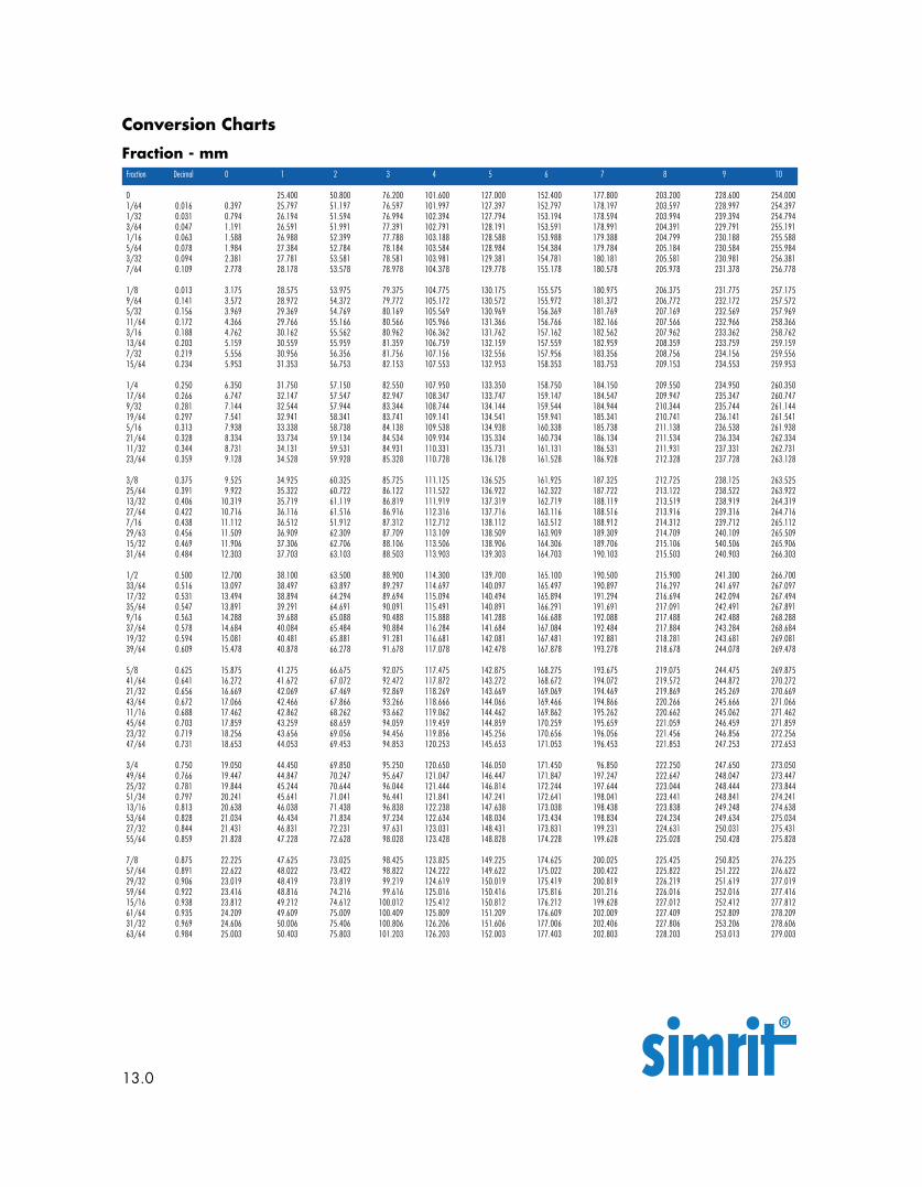
Fraction Decimal 0 1 2 3 4 5 6 7 8 9 10
0 25.400 50.800 76.200 101.600 127.000 152.400 177.800 203.200 228.600 254.0001/64 0.016 0.397 25.797 51.197 76.597 101.997 127.397 152.797 178.197 203.597 228.997 254.3971/32 0.031 0.794 26.194 51.594 76.994 102.394 127.794 153.194 178.594 203.994 239.394 254.7943/64 0.047 1.191 26.591 51.991 77.391 102.791 128.191 153.591 178.991 204.391 229.791 255.1911/16 0.063 1.588 26.988 52.399 77.788 103.188 128.588 153.988 179.388 204.799 230.188 255.5885/64 0.078 1.984 27.384 52.784 78.184 103.584 128.984 154.384 179.784 205.184 230.584 255.9843/32 0.094 2.381 27.781 53.581 78.581 103.981 129.381 154.781 180.181 205.581 230.981 256.3817/64 0.109 2.778 28.178 53.578 78.978 104.378 129.778 155.178 180.578 205.978 231.378 256.778
1/8 0.013 3.175 28.575 53.975 79.375 104.775 130.175 155.575 180.975 206.375 231.775 257.1759/64 0.141 3.572 28.972 54.372 79.772 105.172 130.572 155.972 181.372 206.772 232.172 257.5725/32 0.156 3.969 29.369 54.769 80.169 105.569 130.969 156.369 181.769 207.169 232.569 257.96911/64 0.172 4.366 29.766 55.166 80.566 105.966 131.366 156.766 182.166 207.566 232.966 258.3663/16 0.188 4.762 30.162 55.562 80.962 106.362 131.762 157.162 182.562 207.962 233.362 258.76213/64 0.203 5.159 30.559 55.959 81.359 106.759 132.159 157.559 182.959 208.359 233.759 259.1597/32 0.219 5.556 30.956 56.356 81.756 107.156 132.556 157.956 183.356 208.756 234.156 259.55615/64 0.234 5.953 31.353 56.753 82.153 107.553 132.953 158.353 183.753 209.153 234.553 259.953
1/4 0.250 6.350 31.750 57.150 82.550 107.950 133.350 158.750 184.150 209.550 234.950 260.35017/64 0.266 6.747 32.147 57.547 82.947 108.347 133.747 159.147 184.547 209.947 235.347 260.7479/32 0.281 7.144 32.544 57.944 83.344 108.744 134.144 159.544 184.944 210.344 235.744 261.14419/64 0.297 7.541 32.941 58.341 83.741 109.141 134.541 159.941 185.341 210.741 236.141 261.5415/16 0.313 7.938 33.338 58.738 84.138 109.538 134.938 160.338 185.738 211.138 236.538 261.93821/64 0.328 8.334 33.734 59.134 84.534 109.934 135.334 160.734 186.134 211.534 236.334 262.33411/32 0.344 8.731 34.131 59.531 84.931 110.331 135.731 161.131 186.531 211.931 237.331 262.73123/64 0.359 9.128 34.528 59.928 85.328 110.728 136.128 161.528 186.928 212.328 237.728 263.128
3/8 0.375 9.525 34.925 60.325 85.725 111.125 136.525 161.925 187.325 212.725 238.125 263.52525/64 0.391 9.922 35.322 60.722 86.122 111.522 136.922 162.322 187.722 213.122 238.522 263.92213/32 0.406 10.319 35.719 61.119 86.819 111.919 137.319 162.719 188.119 213.519 238.919 264.31927/64 0.422 10.716 36.116 61.516 86.916 112.316 137.716 163.116 188.516 213.916 239.316 264.7167/16 0.438 11.112 36.512 51.912 87.312 112.712 138.112 163.512 188.912 214.312 239.712 265.11229/63 0.456 11.509 36.909 62.309 87.709 113.109 138.509 163.909 189.309 214.709 240.109 265.50915/32 0.469 11.906 37.306 62.706 88.106 113.506 138.906 164.306 189.706 215.106 540.506 265.90631/64 0.484 12.303 37.703 63.103 88.503 113.903 139.303 164.703 190.103 215.503 240.903 266.303
1/2 0.500 12.700 38.100 63.500 88.900 114.300 139.700 165.100 190.500 215.900 241.300 266.70033/64 0.516 13.097 38.497 63.897 89.297 114.697 140.097 165.497 190.897 216.297 241.697 267.09717/32 0.531 13.494 38.894 64.294 89.694 115.094 140.494 165.894 191.294 216.694 242.094 267.49435/64 0.547 13.891 39.291 64.691 90.091 115.491 140.891 166.291 191.691 217.091 242.491 267.8919/16 0.563 14.288 39.688 65.088 90.488 115.888 141.288 166.688 192.088 217.488 242.488 268.28837/64 0.578 14.684 40.084 65.484 90.884 116.284 141.684 167.084 192.484 217.884 243.284 268.68419/32 0.594 15.081 40.481 65.881 91.281 116.681 142.081 167.481 192.881 218.281 243.681 269.08139/64 0.609 15.478 40.878 66.278 91.678 117.078 142.478 167.878 193.278 218.678 244.078 269.478
5/8 0.625 15.875 41.275 66.675 92.075 117.475 142.875 168.275 193.675 219.075 244.475 269.87541/64 0.641 16.272 41.672 67.072 92.472 117.872 143.272 168.672 194.072 219.572 244.872 270.27221/32 0.656 16.669 42.069 67.469 92.869 118.269 143.669 169.069 194.469 219.869 245.269 270.66943/64 0.672 17.066 42.466 67.866 93.266 118.666 144.066 169.466 194.866 220.266 245.666 271.06611/16 0.688 17.462 42.862 68.262 93.662 119.062 144.462 169.862 195.262 220.662 245.062 271.46245/64 0.703 17.859 43.259 68.659 94.059 119.459 144.859 170.259 195.659 221.059 246.459 271.85923/32 0.719 18.256 43.656 69.056 94.456 119.856 145.256 170.656 196.056 221.456 246.856 272.25647/64 0.731 18.653 44.053 69.453 94.853 120.253 145.653 171.053 196.453 221.853 247.253 272.653
3/4 0.750 19.050 44.450 69.850 95.250 120.650 146.050 171.450 96.850 222.250 247.650 273.05049/64 0.766 19.447 44.847 70.247 95.647 121.047 146.447 171.847 197.247 222.647 248.047 273.44725/32 0.781 19.844 45.244 70.644 96.044 121.444 146.814 172.244 197.644 223.044 248.444 273.84451/34 0.797 20.241 45.641 71.041 96.441 121.841 147.241 172.641 198.041 223.441 248.841 274.24113/16 0.813 20.638 46.038 71.438 96.838 122.238 147.638 173.038 198.438 223.838 249.248 274.63853/64 0.828 21.034 46.434 71.834 97.234 122.634 148.034 173.434 198.834 224.234 249.634 275.03427/32 0.844 21.431 46.831 72.231 97.631 123.031 148.431 173.831 199.231 224.631 250.031 275.43155/64 0.859 21.828 47.228 72.628 98.028 123.428 148.828 174.228 199.628 225.028 250.428 275.828
7/8 0.875 22.225 47.625 73.025 98.425 123.825 149.225 174.625 200.025 225.425 250.825 276.22557/64 0.891 22.622 48.022 73.422 98.822 124.222 149.622 175.022 200.422 225.822 251.222 276.62229/32 0.906 23.019 48.419 73.819 99.219 124.619 150.019 175.419 200.819 226.219 251.619 277.01959/64 0.922 23.416 48.816 74.216 99.616 125.016 150.416 175.816 201.216 226.016 252.016 277.41615/16 0.938 23.812 49.212 74.612 100.012 125.412 150.812 176.212 199.628 227.012 252.412 277.81261/64 0.935 24.209 49.609 75.009 100.409 125.809 151.209 176.609 202.009 227.409 252.809 278.20931/32 0.969 24.606 50.006 75.406 100.806 126.206 151.606 177.006 202.406 227.806 253.206 278.60663/64 0.984 25.003 50.403 75.803 101.203 126.203 152.003 177.403 202.803 228.203 253.013 279.003
Conversion Charts
Fraction - mm Medium Temp.C NBR HNBR ACM VMQ FPM PTFE
13.0
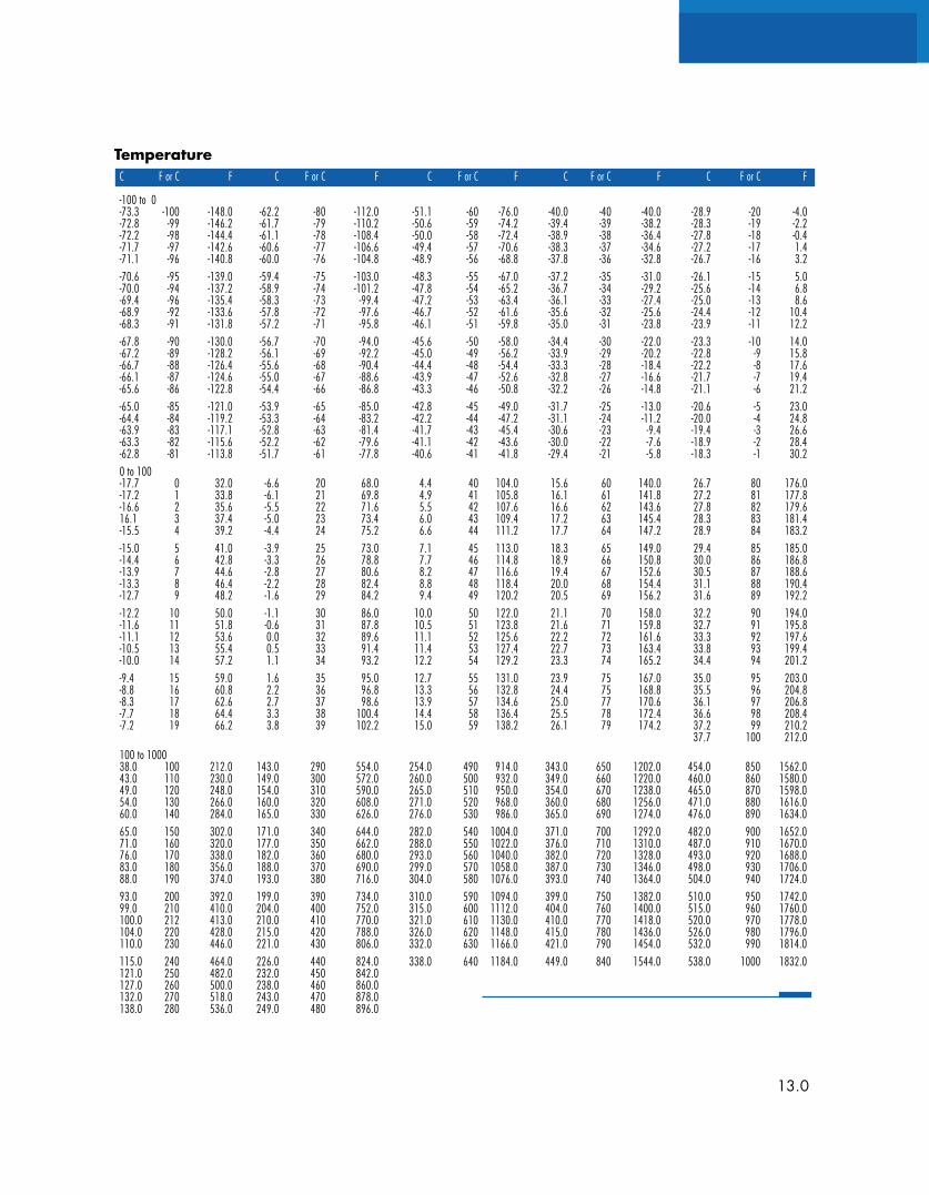
TemperatureC F or C F C F or C F C F or C F C F or C F C F or C F
-100 to 0-73.3 -100 -148.0 -62.2 -80 -112.0 -51.1 -60 -76.0 -40.0 -40 -40.0 -28.9 -20 -4.0-72.8 -99 -146.2 -61.7 -79 -110.2 -50.6 -59 -74.2 -39.4 -39 -38.2 -28.3 -19 -2.2-72.2 -98 -144.4 -61.1 -78 -108.4 -50.0 -58 -72.4 -38.9 -38 -36.4 -27.8 -18 -0.4-71.7 -97 -142.6 -60.6 -77 -106.6 -49.4 -57 -70.6 -38.3 -37 -34.6 -27.2 -17 1.4-71.1 -96 -140.8 -60.0 -76 -104.8 -48.9 -56 -68.8 -37.8 -36 -32.8 -26.7 -16 3.2-70.6 -95 -139.0 -59.4 -75 -103.0 -48.3 -55 -67.0 -37.2 -35 -31.0 -26.1 -15 5.0-70.0 -94 -137.2 -58.9 -74 -101.2 -47.8 -54 -65.2 -36.7 -34 -29.2 -25.6 -14 6.8-69.4 -96 -135.4 -58.3 -73 -99.4 -47.2 -53 -63.4 -36.1 -33 -27.4 -25.0 -13 8.6-68.9 -92 -133.6 -57.8 -72 -97.6 -46.7 -52 -61.6 -35.6 -32 -25.6 -24.4 -12 10.4-68.3 -91 -131.8 -57.2 -71 -95.8 -46.1 -51 -59.8 -35.0 -31 -23.8 -23.9 -11 12.2-67.8 -90 -130.0 -56.7 -70 -94.0 -45.6 -50 -58.0 -34.4 -30 -22.0 -23.3 -10 14.0-67.2 -89 -128.2 -56.1 -69 -92.2 -45.0 -49 -56.2 -33.9 -29 -20.2 -22.8 -9 15.8-66.7 -88 -126.4 -55.6 -68 -90.4 -44.4 -48 -54.4 -33.3 -28 -18.4 -22.2 -8 17.6-66.1 -87 -124.6 -55.0 -67 -88.6 -43.9 -47 -52.6 -32.8 -27 -16.6 -21.7 -7 19.4-65.6 -86 -122.8 -54.4 -66 -86.8 -43.3 -46 -50.8 -32.2 -26 -14.8 -21.1 -6 21.2-65.0 -85 -121.0 -53.9 -65 -85.0 -42.8 -45 -49.0 -31.7 -25 -13.0 -20.6 -5 23.0-64.4 -84 -119.2 -53.3 -64 -83.2 -42.2 -44 -47.2 -31.1 -24 -11.2 -20.0 -4 24.8-63.9 -83 -117.1 -52.8 -63 -81.4 -41.7 -43 -45.4 -30.6 -23 -9.4 -19.4 -3 26.6-63.3 -82 -115.6 -52.2 -62 -79.6 -41.1 -42 -43.6 -30.0 -22 -7.6 -18.9 -2 28.4-62.8 -81 -113.8 -51.7 -61 -77.8 -40.6 -41 -41.8 -29.4 -21 -5.8 -18.3 -1 30.20 to 100-17.7 0 32.0 -6.6 20 68.0 4.4 40 104.0 15.6 60 140.0 26.7 80 176.0-17.2 1 33.8 -6.1 21 69.8 4.9 41 105.8 16.1 61 141.8 27.2 81 177.8-16.6 2 35.6 -5.5 22 71.6 5.5 42 107.6 16.6 62 143.6 27.8 82 179.616.1 3 37.4 -5.0 23 73.4 6.0 43 109.4 17.2 63 145.4 28.3 83 181.4-15.5 4 39.2 -4.4 24 75.2 6.6 44 111.2 17.7 64 147.2 28.9 84 183.2-15.0 5 41.0 -3.9 25 73.0 7.1 45 113.0 18.3 65 149.0 29.4 85 185.0-14.4 6 42.8 -3.3 26 78.8 7.7 46 114.8 18.9 66 150.8 30.0 86 186.8-13.9 7 44.6 -2.8 27 80.6 8.2 47 116.6 19.4 67 152.6 30.5 87 188.6-13.3 8 46.4 -2.2 28 82.4 8.8 48 118.4 20.0 68 154.4 31.1 88 190.4-12.7 9 48.2 -1.6 29 84.2 9.4 49 120.2 20.5 69 156.2 31.6 89 192.2-12.2 10 50.0 -1.1 30 86.0 10.0 50 122.0 21.1 70 158.0 32.2 90 194.0-11.6 11 51.8 -0.6 31 87.8 10.5 51 123.8 21.6 71 159.8 32.7 91 195.8-11.1 12 53.6 0.0 32 89.6 11.1 52 125.6 22.2 72 161.6 33.3 92 197.6-10.5 13 55.4 0.5 33 91.4 11.4 53 127.4 22.7 73 163.4 33.8 93 199.4-10.0 14 57.2 1.1 34 93.2 12.2 54 129.2 23.3 74 165.2 34.4 94 201.2-9.4 15 59.0 1.6 35 95.0 12.7 55 131.0 23.9 75 167.0 35.0 95 203.0-8.8 16 60.8 2.2 36 96.8 13.3 56 132.8 24.4 75 168.8 35.5 96 204.8-8.3 17 62.6 2.7 37 98.6 13.9 57 134.6 25.0 77 170.6 36.1 97 206.8-7.7 18 64.4 3.3 38 100.4 14.4 58 136.4 25.5 78 172.4 36.6 98 208.4-7.2 19 66.2 3.8 39 102.2 15.0 59 138.2 26.1 79 174.2 37.2 99 210.2
37.7 100 212.0100 to 100038.0 100 212.0 143.0 290 554.0 254.0 490 914.0 343.0 650 1202.0 454.0 850 1562.043.0 110 230.0 149.0 300 572.0 260.0 500 932.0 349.0 660 1220.0 460.0 860 1580.049.0 120 248.0 154.0 310 590.0 265.0 510 950.0 354.0 670 1238.0 465.0 870 1598.054.0 130 266.0 160.0 320 608.0 271.0 520 968.0 360.0 680 1256.0 471.0 880 1616.060.0 140 284.0 165.0 330 626.0 276.0 530 986.0 365.0 690 1274.0 476.0 890 1634.065.0 150 302.0 171.0 340 644.0 282.0 540 1004.0 371.0 700 1292.0 482.0 900 1652.071.0 160 320.0 177.0 350 662.0 288.0 550 1022.0 376.0 710 1310.0 487.0 910 1670.076.0 170 338.0 182.0 360 680.0 293.0 560 1040.0 382.0 720 1328.0 493.0 920 1688.083.0 180 356.0 188.0 370 690.0 299.0 570 1058.0 387.0 730 1346.0 498.0 930 1706.088.0 190 374.0 193.0 380 716.0 304.0 580 1076.0 393.0 740 1364.0 504.0 940 1724.093.0 200 392.0 199.0 390 734.0 310.0 590 1094.0 399.0 750 1382.0 510.0 950 1742.099.0 210 410.0 204.0 400 752.0 315.0 600 1112.0 404.0 760 1400.0 515.0 960 1760.0100.0 212 413.0 210.0 410 770.0 321.0 610 1130.0 410.0 770 1418.0 520.0 970 1778.0104.0 220 428.0 215.0 420 788.0 326.0 620 1148.0 415.0 780 1436.0 526.0 980 1796.0110.0 230 446.0 221.0 430 806.0 332.0 630 1166.0 421.0 790 1454.0 532.0 990 1814.0115.0 240 464.0 226.0 440 824.0 338.0 640 1184.0 449.0 840 1544.0 538.0 1000 1832.0121.0 250 482.0 232.0 450 842.0127.0 260 500.0 238.0 460 860.0132.0 270 518.0 243.0 470 878.0138.0 280 536.0 249.0 480 896.0
13.0


Service Freudenberg–NOK Sealing Technologies
Publication No. 4100 © 2011 Simrit
www.simrit.com +1 (866) 274 6748
Simrit Americas
Elgin, Illinois, USA
Te l: +1 (866) 274 6748
Fax: +1 (847) 783 6519
Simrit Europe
Weinheim, Germany
Tel: +49 (0) 18 05 – 746748
Fax: +49 (0) 18 03 – 746748
Simrit China
Shanghai, China
Tel: +86 (21) 50 36 69 00
Fax: +86 (21) 50 36 63 07