RADIAL GATES - Hydro Gate...This is a vertical ... A hoist with an electrically operated lift...
12
RADIAL GATES
Transcript of RADIAL GATES - Hydro Gate...This is a vertical ... A hoist with an electrically operated lift...
RADIAL GATES
Description
TABLE OF CONTENTSApplications ....................................................................................................................................................................................................................................................................................1
Description ......................................................................................................................................................................................................................................................................................1
Construction ..............................................................................................................................................................................................................................................................................1-2
Seals ...............................................................................................................................................................................................................................................................................................2-3
Hoist .................................................................................................................................................................................................................................................................................................. 3
Radial Gate Drawings ............................................................................................................................................................................................................................................................4-5
Specifications ............................................................................................................................................................................................................................................................................6-7
Description
DESCRIPTIONHydro Gate® standard radial gates are designed for a wide, clear waterway opening. A radial (or taintor) gate acts similar to a section of a drum. Pressure is transferred from the curved face through the horizontal support beams to the radial arms at the sides of the opening. The arms act as columns and transfer thrust to a common bearing located on either side of the gate opening. Flow is underneath the curved face as the gate is opened. This design results in a lightweight, economical gate that can be opened and closed with minimum effort and with comparatively small number of turns of the handwheel on the hoist.
Hydro Gate radial gates are made for two types of installations. The first, and most commonly used, is an overflow type. This gate is designed for 1 ft of water flowing over the top of the gate when the gate is closed. Adequate safety factors prevent damage to the gate if there is a moderate, additional overflow beyond that limit for a short period of time.
The second type employs the use of a breastwall. This is a vertical concrete wall above the top of the gate opening that results in additional storage capacity in front of the gate. Most radial gates are raise-to-open type, a variation is the lower-to-open type. This requires a weir wall for mounting a seal that must make contact with the curved face plate. Silt and debris entrapment is a problem with this arrangement.
CONSTRUCTIONGATE FACEThe standard radial gate face is constructed by using horizontal structural members and a curved face plate. The curved steel face plate is 1/4" minimum thickness.
The face plate is attached to the horizontal structural members by welding. Sufficient holes are located around the perimeter of the assembly for attaching the seals.
HORIZONTAL SUPPORT BEAMSHorizontal face support beams are made from structural steel channels. These beams vary in size with the width of the gate and maximum head of water. They also vary in quantity and spacing with the height of the gate. Welded to the end of each channel is a heavy steel gusset with holes punched to receive the side arms. These support beams are normally painted. They can be hot-dip galvanized for additional corrosion protection.
RADIAL (TAINTOR) GATES
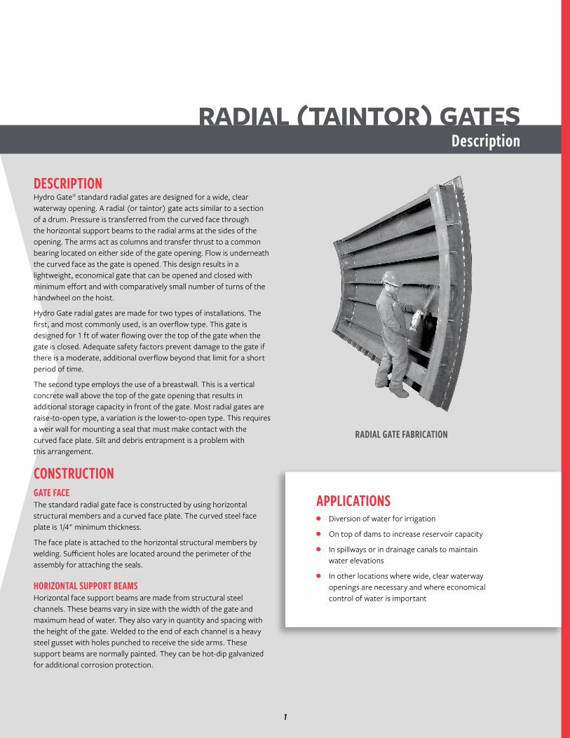
RADIAL GATE FABRICATION
APPLICATIONS• Diversion of water for irrigation
• On top of dams to increase reservoir capacity
• In spillways or in drainage canals to maintain water elevations
• In other locations where wide, clear waterway openings are necessary and where economical control of water is important
1
Construction
RADIAL ARMS AND PIN PLATERadial arms are fabricated from structural steel angles, with larger and thicker angles being used as the gate height increases. Each angle acts as a column in transmitting the load from the face support channel to the pin plate. The forward or upstream end of each angle is punched with holes to match those in the gusset plate. The back end of each angle terminates at a common pin plate in a fan-like arrangement. This steel pin plate is made thicker as the gate height, width, and head increase. A steel collar is welded to the pin plate to form a hub to receive the pin. The hub and pin are cross drilled to hold the gate pin in position. The pin is removable to facilitate installation of the gate. The entire assembly is painted, or it can be hot-dip galvanized along with the face support beams.
BEARING AND PIN ASSEMBLY DRAWINGPin bearings are a heavy cast iron or fabricated housing and are bored to receive the pin. Bearings are supplied with "fins" to firmly anchor them and distribute the total thrust to the concrete. Pin bearings may be aligned and supported in the forms and concrete poured around them, or a recess can be formed at the proper location in the side walls and the bearings can be grouted in place after the gate is installed. Fabricated brackets to hold the pin bearing can also be mounted to the surface of the channel walls. Removable cold-rolled steel pins of the proper diameter are supplied to transmit the thrust on the gate to the pin bearings. The pin bearing is located high and downstream out of the water and requires no lubrication.
SEALSSIDE SEALSSide seals on both the overflow and breastwall gates are made from neoprene. The standard side seal is a J-seal bolted to the edge of the face plate and is held in place by a steel retainer bar. The side seal is adjusted to compress against the side rubbing plate to form a watertight seal.
BOTTOM SEALThe bottom seal is also a J-seal that is attached to the gate by bolting. As the gate closes, its weight causes a slight deflection in the seal as it contacts the invert of the opening. This flexibility allows the bottom seal to compensate for slight irregularities in the concrete floor. However, if the floor is out of level by more than 1/8", the seal will not compensate for this much difference and excessive leakage will result. To minimize this possible discrepancy in construction, an adjustable sill as described in this section is recommended.
TOP SEALThe top seal on a breastwall-type radial gate is made by attaching a flat section of rubber to the underneath side of the breastwall. An angle attached along the top front face of the gate projects toward the breastwall and forms the other portion of the seal. As the gate is closed, the protruding leg on the angle makes contact with the rubber projecting from the breastwall and seals the space along the top of the opening. The hoist ropes pass through a slit in the seal, allowing some leakage.
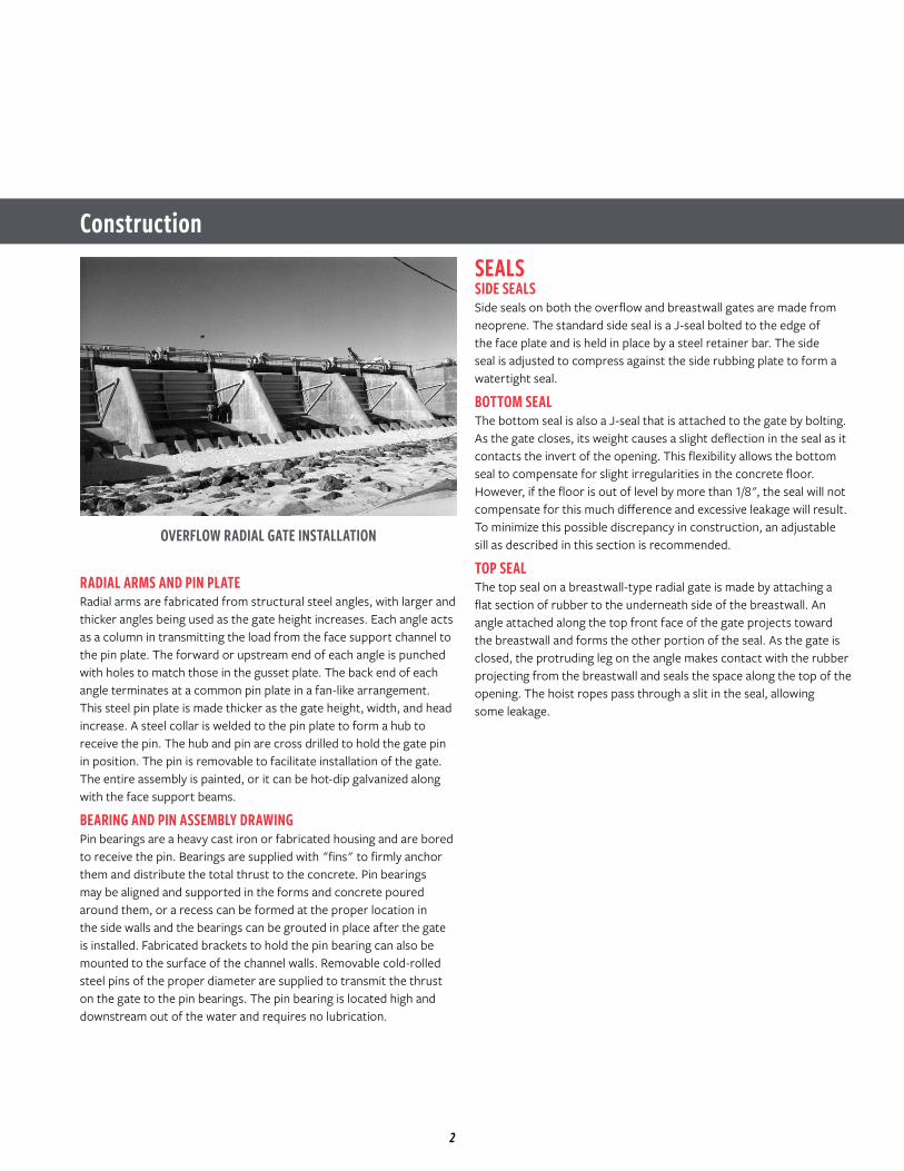
OVERFLOW RADIAL GATE INSTALLATION
2
HoistADJUSTABLE SILL AND SIDE RUBBING PLATESTo improve the operation and water-tightness of a radial gate, adjustable side rubbing plates and an adjustable bottom sill are recommended. These plates are available in stainless steel or galvanized steel.
During construction, a recess is left at the sides and bottom of the gate opening where the adjustable rubbing plates and the bottom sill are to be mounted. Anchor bolts are set in the forms and extend into the recesses. Projection of these anchors is less than the depth of the recess.
When forms are stripped, the adjustable plates are installed on the projecting anchors. By use of double nuts on each anchor, the side rubbing plates and bottom sill can be properly aligned. Side rubbing plates are adjusted with the gate closed to obtain a good seal fit and compression. Side seals and side rubbing plates should be adjusted so that a slight wedge-shaped opening is formed to reduce seal drag and wear as the gate opens. The bottom sill plate must be flat across its entire width, in good contact with the bottom gate seal, and as flush as possible with the invert.
As an alignment check, the gate should operate to ensure that proper contact is being made with the rubber seals on the gate. All plates are then grouted in to complete the gate installation. The drawings on page 5 show details of adjustable side rubbing plates and of the adjustable bottom sill.
SIDE SEALSAnother type of side seal available is the flat type. This is a more economical seal due to the fact that side rubbing plates are not required. It can be used for retrofitting gates in existing structures where cutting and chipping of concrete for placement of rubbing plates is not desired. The walls must be parallel, flat and perpendicular to the invert within the compliance of the flat seal. Leakage control provided by flat-type seals may not be as good as leakage control provided by J-seals and rubbing plates.
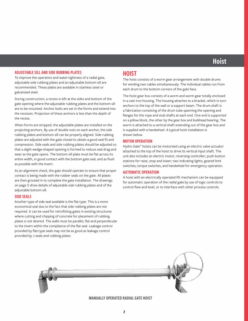
HOISTThe hoist consists of a worm gear arrangement with double drums for winding two cables simultaneously. The individual cables run from each drum to the bottom corners of the gate face.
The hoist gear box consists of a worm and worm gear totally enclosed in a cast iron housing. The housing attaches to a bracket, which in turn anchors to the top of the wall or a support beam. The drum shaft is a fabrication consisting of the drum tube spanning the opening and flanges for the rope and stub shafts at each end. One end is supported on a pillow block, the other by the gear box and bulkhead bearing. The worm is attached to a vertical shaft extending out of the gear box and is supplied with a handwheel. A typical hoist installation is shown below.
MOTOR OPERATIONHydro Gate® hoists can be motorized using an electric valve actuator attached to the top of the hoist to drive its vertical input shaft. The unit also includes an electric motor; reversing controller; push-button stations for raise, stop and lower; two indicating lights; geared limit switches; torque switches; and handwheel for emergency operation.
AUTOMATIC OPERATIONA hoist with an electrically operated lift mechanism can be equipped for automatic operation of the radial gate by use of logic controls to control flow and level, or to interface with other process controls.
MANUALLY OPERATED RADIAL GATE HOIST
3
Radial Gate Drawings
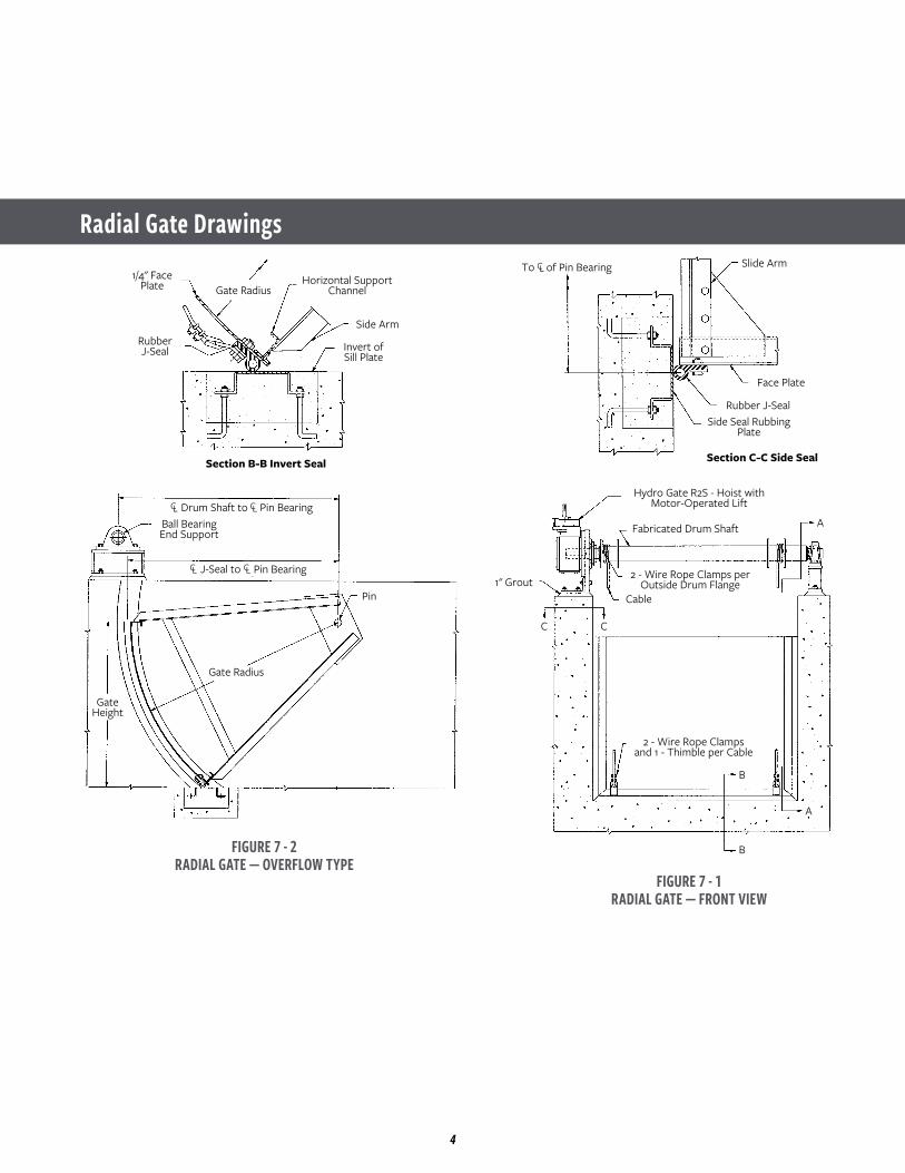
FIGURE 7 - 2RADIAL GATE — OVERFLOW TYPE
FIGURE 7 - 1RADIAL GATE — FRONT VIEW
1/4" FacePlate
RubberJ-Seal Invert of
Sill Plate
Section B-B Invert Seal
Side Arm
Horizontal SupportChannelGate Radius
Gate Radius
1" Grout
C C
A
Pin
Ball BearingEnd Support
GateHeight
Drum Shaft to Pin BearingCLCL
J-Seal to Pin BearingCLCL
To of Pin BearingCL Slide Arm
Face Plate
Rubber J-SealSide Seal Rubbing
Plate
Fabricated Drum Shaft
2 - Wire Rope Clamps perOutside Drum Flange
2 - Wire Rope Clampsand 1 - Thimble per Cable
Hydro Gate R2S - Hoist withMotor-Operated Lift
Cable
A
B
B
Section C-C Side Seal
4
Radial Gate Drawings
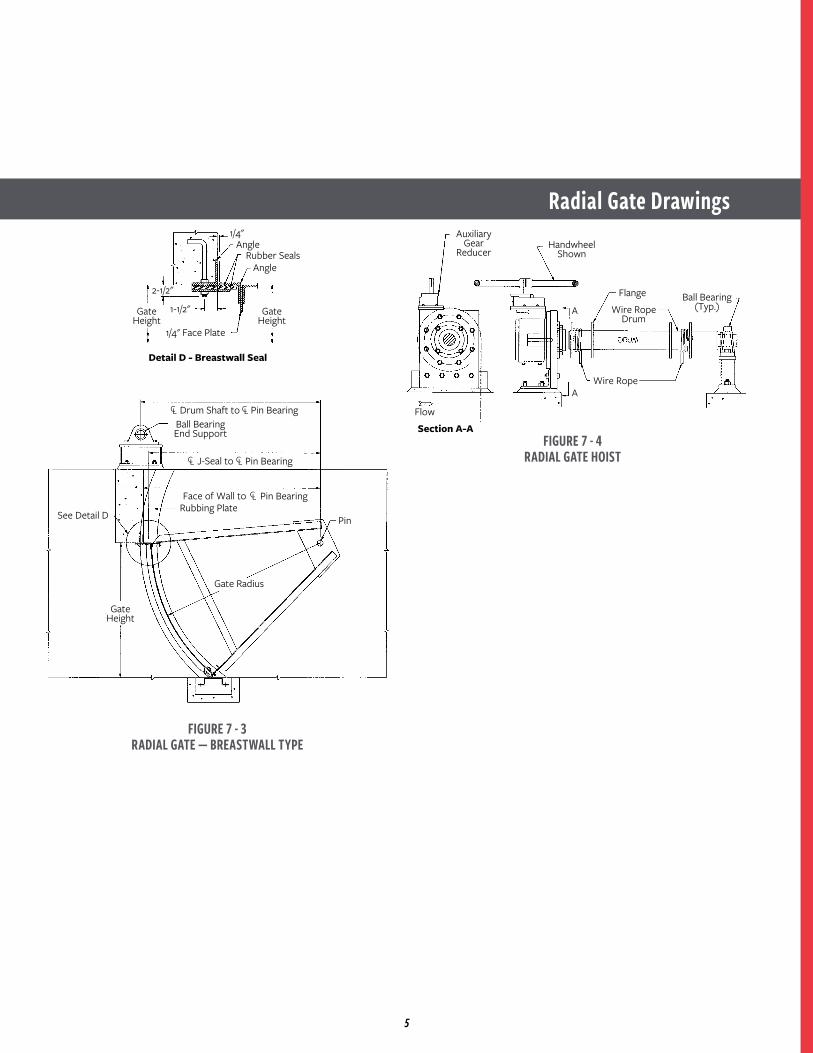
FIGURE 7 - 3RADIAL GATE — BREASTWALL TYPE
FIGURE 7 - 4RADIAL GATE HOIST
Rubbing PlateSee Detail D
1/4"
1-1/2"
2-1/2"
Angle
AngleRubber Seals
1/4" Face Plate
GateHeight
GateHeight
GateHeight
Section A-A
Detail D - Breastwall Seal
Drum Shaft to Pin BearingCLCL
J-Seal to Pin BearingCLCL
Face of Wall to Pin BearingCL
Ball BearingEnd Support
Gate Radius
Pin
AuxiliaryGear
ReducerHandwheel
Shown
Ball Bearing(Typ.)Wire Rope
Drum
Flange
Wire Rope
Flow
A
A
5
SpecificationsPINS AND PIN BEARINGSThe cold-rolled steel pivot pins shall be sized to transmit the load to the pin bearings. They shall be bolted to the pin plate collar for field assembly.
The cast iron pin bearings shall extend into the concrete and have sufficient surface to properly distribute the full load to the structure. The bearing shall be bored full length for a running fit with the pivot pin.
WELDINGManual welding operators performing welding operations on these gates or accessories shall be qualified either under Section 9, Part A, of the ASME Boiler and Pressure Vessel Code, or under the Standard Qualification Procedure of the American Welding Society. All welds shall have complete fusion with the base metal and shall be free from cracks, oxides, slag inclusions and gas pockets.
RADIAL GATE HOISTThe hoist shall consist of a hoist base, gears, cable drums, drumshaft, cables, bearing base, and handwheel to operate the radial gate.
Gears shall be cast iron or steel, accurately machined with cut teeth, smooth running with suitable shafts of cold-rolled steel. The cast iron housing shall be machined to receive all shafting and shall hold gears in alignment without binding. All gearing and shafting shall be suitable for auxiliary motor operation.
The hoist shall be furnished with cold-rolled steel drum shaft and two fabricated drums manufactured from pipe. Each drum will have an inner and outer flange to aid in guiding the wire rope. Stainless steel cables and clamps shall be furnished for field connection of the cables to the bottom corners of the gate.
The design of the hoist mechanism shall be such that the radial gate can be operated with no more than 40-lb effort of the 30". diameter cast iron handwheel. The direction of rotation to open the gate shall be cast on the handwheel rim. Anchor bolts shall be provided to attach the hoist and bearing base to the concrete.
When the hoist is to be motorized, the handwheel shall be omitted. The input shaft of the hoist shall be furnished with a key and keyway to attach the electrically operated unit.
SPECIFICATIONS FOR RADIAL (TAINTOR) GATESGENERALGates, hoist, and accessories shall be of the size, material, and construction shown on the manufacturer's drawings and specified herein. They shall be Hydro Gate® overflow-type or breastwall-type radial gates or approved equal. Similar installations shall have operated successfully for ten years or more. All component parts shall be of the type material shown in the "Materials" section of the specification. An installation list showing five similar projects will be required.
DESIGNOverflow-type gates shall be designed to withstand a water depth of 1' greater than the vertical height of the gate. The breastwall-type gate shall be designed to withstand a water depth of 10 ft on the invert. Maximum face deflection shall be 1/360 of the width.
Design loads placed on the structural reinforcing channels shall not induce stresses in excess of those specified in Section 1.5.1.4 of AISC specification for structural steel building. The slenderness ratio of the radial arms shall not exceed 200. The curved face plate shall be 1/4" minimum.
GATE FACE ASSEMBLY DRAWINGThe face assembly shall consist of horizontal structural members and a curved face plate. Horizontal structural members shall be of adequate size and correctly located to transmit the thrust from the face of the gate to the radial arms. The steel face plate shall be attached to the structures by welding. Sufficient holes shall be located around the perimeter of the assembly for attaching the seals.
The side seals and the top seal for breastwall-type gates shall be flat rubber held in place by steel retainer. The bottom seal shall be rubber of the hollow J-seal type.
RADIAL ARMSThe radial arm assemblies shall consist of structural angles welded to a pin plate and punched to match gusset plates welded to the horizontal structural members of the face assembly. Bolts for field assembly shall be provided.
The steel pin plate shall transmit the load from the radial arms to the pivot pin. A steel collar shall be welded to the pin plate to distribute the bearing load on the pin. It shall be match drilled with the pin.
6
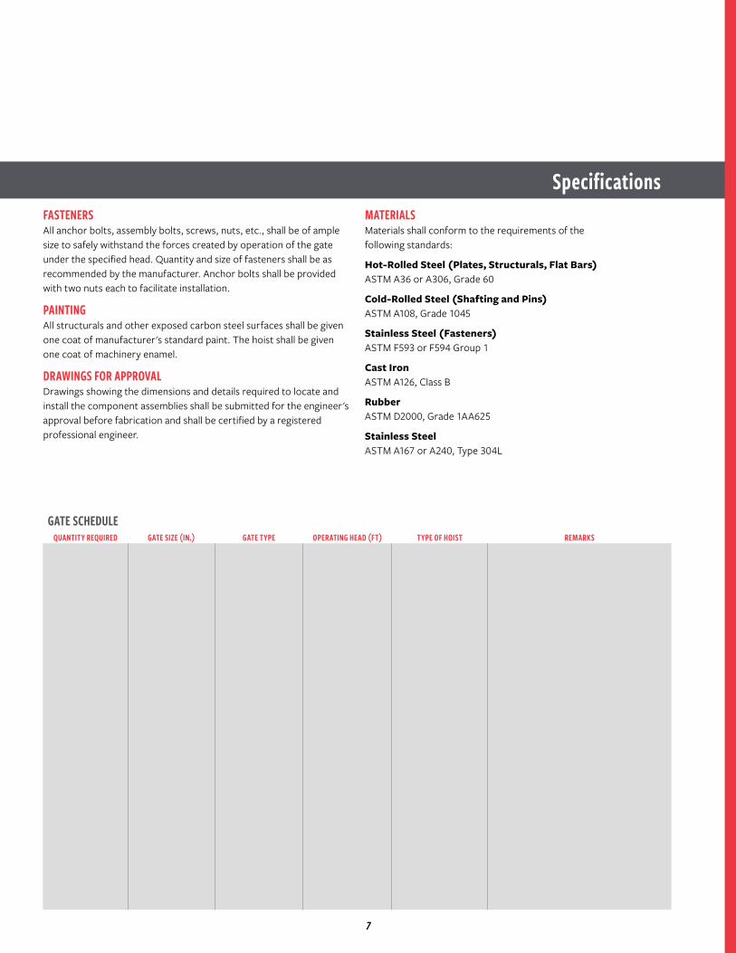
SpecificationsFASTENERSAll anchor bolts, assembly bolts, screws, nuts, etc., shall be of ample size to safely withstand the forces created by operation of the gate under the specified head. Quantity and size of fasteners shall be as recommended by the manufacturer. Anchor bolts shall be provided with two nuts each to facilitate installation.
PAINTINGAll structurals and other exposed carbon steel surfaces shall be given one coat of manufacturer's standard paint. The hoist shall be given one coat of machinery enamel.
DRAWINGS FOR APPROVALDrawings showing the dimensions and details required to locate and install the component assemblies shall be submitted for the engineer's approval before fabrication and shall be certified by a registered professional engineer.
MATERIALSMaterials shall conform to the requirements of the following standards:
Hot-Rolled Steel (Plates, Structurals, Flat Bars)ASTM A36 or A306, Grade 60
Cold-Rolled Steel (Shafting and Pins)ASTM A108, Grade 1045
Stainless Steel (Fasteners)ASTM F593 or F594 Group 1
Cast IronASTM A126, Class B
RubberASTM D2000, Grade 1AA625
Stainless SteelASTM A167 or A240, Type 304L
GATE SCHEDULEQUANTITY REQUIRED GATE SIZE (IN.) GATE TYPE OPERATING HEAD (FT) TYPE OF HOIST REMARKS
7

NOTES
8

NOTES
9
For more information about us or to view our full line of water products, please visit www.hydrogate.com or call Hydro Gate® customer service at 1.800.423.1323.Mueller refers to one or more of Mueller Water Products, Inc., a Delaware corporation ("MWP"), and its subsidiaries. MWP and each of subsidiaries are legally separate and independent entities when providing products and services. MWP does not provide products or services to third parties. MWP and each of its subsidiaries are liable only for their own acts and omissions and not those of each other. MWP brands include Mueller®, Echologics®, Hydro Gate®, Hydro-Guard®, Jones®, Mi.Net®, Milliken®, Pratt®, Singer®, and U.S. Pipe Valve & Hydrant. Please see www.muellerwp.com/about to learn more.
Copyright © 2019 Henry Pratt Company, LLC. All Rights Reserved. The trademarks, logos and service marks displayed in this document are the property of Mueller Water Products, Inc., its affiliates or other third parties. Products marked with a section symbol (§) are subject to patents or patent applications. For details, visit www.mwppat.com. These products are intended for use in potable water applications. Please contact your Mueller Sales or Customer Service Representative concerning any other application(s).
F 13764 1/19
OUR MISSION IS TO BE THE LEADING WATER CONTROL GATE MANUFACTURER IN THE WORLD, THROUGH CONTINUOUS DEVELOPMENT OF AN ORGANIZATION WHICH PROMOTES EXTRAORDINARY CUSTOMER SERVICE, SUPERIOR ENGINEERING, QUALITY PRODUCTS AND ON-TIME DELIVERY.