Radar Warning Receiver Testing - UNITRONIX...Overview • Radar Warning Receiver (RWR) are an...
12
www.d-ta.com Radar Warning Receiver Testing D-TA’s MRSE Series of Products for RWR testing in System Integration Lab (SIL) Environment
Transcript of Radar Warning Receiver Testing - UNITRONIX...Overview • Radar Warning Receiver (RWR) are an...

www.d-ta.com
Radar Warning Receiver TestingD-TA’s MRSE Series of Products for RWR testing in System Integration Lab (SIL) Environment
tim
New Stamp

Overview
• Radar Warning Receiver (RWR) are an integral part of an airborne Electronic Warfare (EW) self-protection suite.
• Basic function of an RWR is to detect the presence of RF emitters in the environment.
• RWR testing occurs at different types of facilities depending on the maturity of the system:
• System Integration Laboratories (SIL) at Manufacturer or Integrator Facilities• Ground Test at Customer Installed System Test Facilities• Flight Test at Open Air Range Facilities• Pre-Flight Test for Operational Verification and Readiness
• MRSE Series of Products can be easily configured to support all test and validation activities.• Focus of this presentation is on RWR testing in SIL Environments.
2

RWR System Performance Measures
• Typical RWR parameters measured during SIL testing:
• Minimal detectable signal• Frequency sensitivity (minimum frequency difference between 2 signals)• Dynamic range• Signal density• Angle of Arrival (AoA) accuracy• Threat declaration time
3

Threat Simulator Requirements
• A Threat Simulator must have the following capabilities to successfully test an RWR in a SIL environment:
• Match the RWR frequency and bandwidth specifications• Simulate Pulse and Continuous Wave radar systems simultaneously • Simulate a dynamic engagement over multiple channels to stimulate each RWR antenna receivers
simultaneously and coherently• Simulate a large number of emitters each with their own antenna and waveform characteristics to
replicate the various threat systems of interest• Simulate signal propagation and atmospheric attenuation effects between all emitters and
receivers• Simulate the platform motion and it effects on signal propagation and detection.• Pre-record any number of scenario variations to develop detailed and comprehensive test plans• Replay pre-recorded scenarios within moments to investigate specific or unexpected system
behavior
4
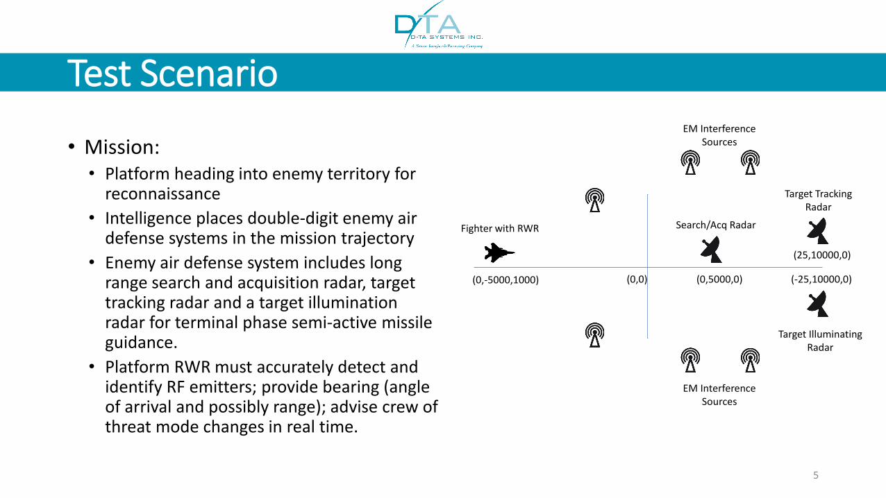
Test Scenario
• Mission:• Platform heading into enemy territory for
reconnaissance • Intelligence places double-digit enemy air
defense systems in the mission trajectory• Enemy air defense system includes long
range search and acquisition radar, target tracking radar and a target illumination radar for terminal phase semi-active missile guidance.
• Platform RWR must accurately detect and identify RF emitters; provide bearing (angle of arrival and possibly range); advise crew of threat mode changes in real time.
5
(0,0) (0,5000,0)
(25,10000,0)
(-25,10000,0)(0,-5000,1000)
Fighter with RWR Search/Acq Radar
Target Tracking Radar
Target Illuminating Radar
EM Interference Sources
EM Interference Sources
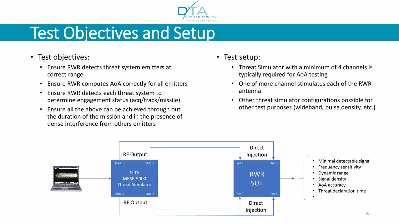
Test Objectives and Setup• Test objectives:
• Ensure RWR detects threat system emitters at correct range
• Ensure RWR computes AoA correctly for all emitters• Ensure RWR detects each threat system to
determine engagement status (acq/track/missile)• Ensure all the above can be achieved through out
the duration of the mission and in the presence of dense interference from others emitters
6
D-TA MRSE-5000
Threat Simulator
RWRSUT
Ant 1Ant 2
Ant 3Ant 4
Chan 1 Chan 2
Chan 3 Chan 4
RF Output
RF Output Direct Injection
Direct Injection
• Test setup:• Threat Simulator with a minimum of 4 channels is
typically required for AoA testing• One of more channel stimulates each of the RWR
antenna• Other threat simulator configurations possible for
other test purposes (wideband, pulse density, etc.)
• Minimal detectable signal• Frequency sensitivity• Dynamic range• Signal density• AoA accuracy• Threat declaration time• …
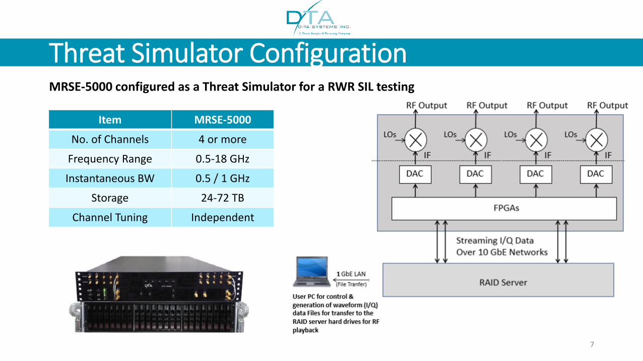
Threat Simulator Configuration
Item MRSE-5000
No. of Channels 4 or more
Frequency Range 0.5-18 GHz
Instantaneous BW 0.5 / 1 GHz
Storage 24-72 TB
Channel Tuning Independent
7
MRSE-5000 configured as a Threat Simulator for a RWR SIL testing

Defining the Test Scenario in MRSETable-based GUI for easy configuration of Test Scenarios
8
Search/Acq RadarTarget Tracking Radar
Pulse Interference Sources
Target Illumination Radar
CW Interference Sources

Defining the Test Scenario in MRSERWR Sensor and Platform Motion Characteristics
RWR Antenna 1-4each on its ownchannel and characteristics
Platform initiallocation and velocity
9
Antenna pointing direction
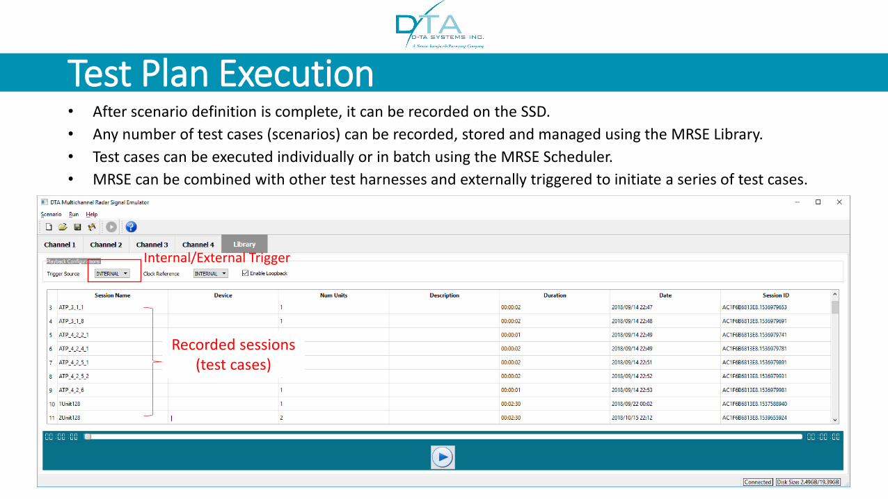
Test Plan Execution• After scenario definition is complete, it can be recorded on the SSD.• Any number of test cases (scenarios) can be recorded, stored and managed using the MRSE Library.• Test cases can be executed individually or in batch using the MRSE Scheduler.• MRSE can be combined with other test harnesses and externally triggered to initiate a series of test cases.
10
Internal/External Trigger
Recorded sessions (test cases)
Conclusion• Test and validation of RWR requires equipment capable of generating complex and realistic scenarios on
multi-channels over a wide frequency range.• MRSE Series of Products can be easily configured to test and validate RWRs in various facilities:
• System Integration Laboratories (SIL) • Ground Test at Customer Installed System Test Facilities• Flight Test at Open Air Range Facilities• Pre-Flight Test for Operational Verification and Readiness
• Major Differentiators of the MRSE Solution:
• Open-architecture and software-driven platforms with user-defined RF channel configuration.• Streaming I/Q simplifies system configuration and allows any waveform to be generated at any
frequency for any duration (virtually unlimited storage).• Systems can have multiple channels to simulate pulse-on-pulse, AOA and high pulse density scenarios.• Scenario and Waveform Generator Software supports the generation of any waveform type,
emitter/receiver dynamics and antenna array design.• Optional receive channel for collecting mission data for hardware-in-the-loop and later playback.
11

For more information visit our website
www.d-ta.com
United StatesD-TA Systems Corp.8 Inverness Drive EastSuite 102Centennial, CO 80112, USA1 877 382 [email protected]
InternationalD-TA Systems Inc.2500 Lancaster RoadOttawa ONK1B 4S5 Canada 1 613 745 [email protected]
Spectrum Processing For Total Dominance!
12
d-ta-systems
d-ta systems