Radar / Collision Avoidance / Navigation for Boaters
43
Radar / Collision Avoidance / Navigation for Boaters By David Vacanti Sr Fellow Advanced Technology Emeritus Honeywell Aerospace 2/2019 Copyright Vacanti Yacht Design LLC 2019
Transcript of Radar / Collision Avoidance / Navigation for Boaters

Radar / Collision Avoidance /
Navigation for Boaters
By David Vacanti
Sr Fellow Advanced Technology Emeritus
Honeywell Aerospace
2/2019 Copyright Vacanti Yacht Design LLC 2019

Gee Martha, that radar is not
working worth a darn today…
Copyright Vacanti Yacht Design LLC 2019

• Value and Purpose of Radar
• AIS Vs Radar
• Radar Basics
• Radar Types
• Radar Image Displays
• Radar Installation
• Safety
• Doppler Vs Standard Radar
• Radar Operation Examples
• Radar Collision Avoidance Examples
• Radar Settings and Controls
• What Radar Can and Cannot Do
• Summary
Agenda – Todays Presentation
Copyright Vacanti Yacht Design LLC 2019

Purpose and Value of Radar • Collision Avoidance
• Above Surface Rocks, Markers, Navigation Buoys
• Other Vessels, Shorelines, Towed Barges behind AIS Tug
• Works in Conjunction with AIS (Automatic ID System)
• Finds true target location with no delay
• Corrects transmitted AIS GPS Location Errors
• Shows non-AIS equipped Targets
• Weather Detection • Detect Rain Squalls
• Navigation • Verify Plotted Chart position Vs Terrain / Navigation Objects
• Flags GPS Location Errors (Spoofing, GPS RX Errors)
• Radar can Measure: • Range
• Angle
• Velocity (Consecutive Scan or Doppler)
• Rain Rate
Copyright Vacanti Yacht Design LLC 2019

If I have AIS why do I need Radar?
AIS is not installed on all vessels – Only Radar can see all vessels
regardless of AIS equipage
AIS transponders can transmit erroneous data if not correctly installed
AIS transponders can be set to Silent Mode (No transmissions)
AIS cannot be used for Navigation in Fog to validate position
Only Radar can see through fog and moderate rain
All Optical sensors are obscured by any atmospheric aerosol
AIS TRANSMIT is generally not installed in 30Kt fishing vessels!!
AIS cannot validate locations of Navigation Buoys in limited visibility
AIS = Automatic
Identification
System
Vessel #1
AIS Xmit
GPS
Transmit Vessel
Name, Location,
Course and Speed
Vessel #2
AIS Receive
Chart Plotter Display Vessel
Name, Location,
Course and Speed Copyright Vacanti Yacht Design LLC 2019

Radar Principals of Operation
Object
Object
Radar cannot see through or around objects.
Therefore objects at short range can mask or
hide objects at longer range.
Radar systems MUST be mounted well clear
of all obstacles to avoid “blanked regions”
and false angle reporting
Object is hidden
from radar by
object in front.
Radar measures
range by time of
flight of transmitted
signal as it returns
to the receiver.
Range resolution
depends on pulse
length or pulse
“chirp” bandwidth
Radar measures
Angle by position of
antenna rotation
angle. Angle
Resolution depends
on antenna size
(beam width).
Wider antennas
provide better
Azimuth angular
resolution
Copyright Vacanti Yacht Design LLC 2019

Marine Radar Antenna Pattern
Radome Antenna System Open Array Antenna System
Horizontal Pattern
(Top Down View)
Vertical Pattern
Elevation View
Antenna Sidelobes and Backlobes can
cause false target detection or angular
extension of targets
Copyright Vacanti Yacht Design LLC 2019

Types of Marine Radar Systems High Power Pulse
Magnetron Transmitter
2,000 to 25,000 Watts Peak Transmit Power
0.2 to 18 Watts Average Transmit Power
Eye / Brain Damage possible at short range
Pulse Compression “CHIRP” Radar
Solid State (Transistor) Transmitter
20 to 80Watts Peak Transmit Power
2 to 8 Watts Average Transmit Power
Pulse Compression – Doppler Radar “CHIRP” Radar
Solid State (Transistor) Transmitter
20 to 80Watts Peak Transmit Power
2 to 8 Watts Average Transmit Power
FMCW (Broadband Radar – Navico) Frequency Modulation – Continuous Wave
“CHIRP” Radar
Solid State (Transistor) Transmitter
0.2 to 0.4Watts Peak Transmit Power
0.2 to 0.4 Watts Average Transmit Power
Copyright Vacanti Yacht Design LLC 2019
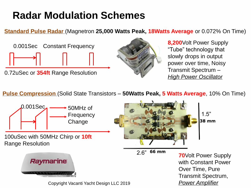
Radar Modulation Schemes
Standard Pulse Radar (Magnetron 25,000 Watts Peak, 18Watts Average or 0.072% On Time)
Pulse Compression (Solid State Transistors – 50Watts Peak, 5 Watts Average, 10% On Time)
8,200Volt Power Supply
“Tube” technology that
slowly drops in output
power over time, Noisy
Transmit Spectrum –
High Power Oscillator
70Volt Power Supply
with Constant Power
Over Time, Pure
Transmit Spectrum,
Power Amplifier
1.5”
2.6”
0.001Sec
0.72uSec or 354ft Range Resolution
0.001Sec
100uSec with 50MHz Chirp or 10ft
Range Resolution
50MHz of
Frequency
Change
Constant Frequency
Copyright Vacanti Yacht Design LLC 2019
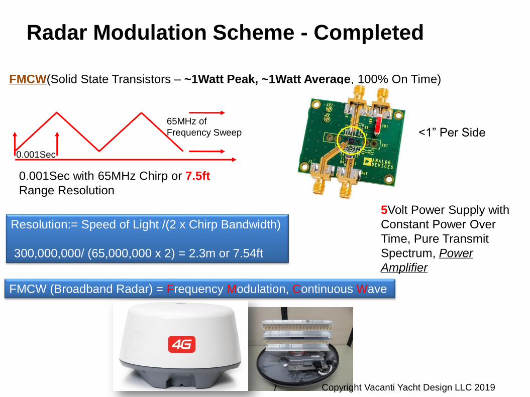
Radar Modulation Scheme - Completed
FMCW(Solid State Transistors – ~1Watt Peak, ~1Watt Average, 100% On Time)
5Volt Power Supply with
Constant Power Over
Time, Pure Transmit
Spectrum, Power
Amplifier
0.001Sec
0.001Sec with 65MHz Chirp or 7.5ft
Range Resolution
65MHz of
Frequency Sweep <1” Per Side
FMCW (Broadband Radar) = Frequency Modulation, Continuous Wave
Resolution:= Speed of Light /(2 x Chirp Bandwidth)
300,000,000/ (65,000,000 x 2) = 2.3m or 7.54ft
Copyright Vacanti Yacht Design LLC 2019

Range and Angle Resolution of Marine Radar Systems
Range Cell
of Length “d”
Range Cell “a’
Degrees wide
Pulse
Length
uSec
Pulse
Bandwidth
in MHz
“d” Cell
length
Antenna
Width
Angular Resolution
“a”
1uSec 1MHz 500ft 2ft 3.4Deg / 326ft at 1Nmi
0.2uSec 5MHz 100ft 3ft 2.3Deg / 221ft at 1Nmi
0.03uSec 33.3MHz 15ft 4ft 1.7Deg / 163ft at 1Nmi
0.02uSec 50MHz 10ft 6ft 1.15Deg / 110ft at 1Nmi
0.002uSec 500MHz 1ft 8ft 0.85Deg / 81ft at 1Nmi
1 uSec = 1millionth of a
second or 0.000,000,1
Seconds
Pulse
Radar
Pulse
Compression or
FMCW Radar
Type of Radar Transmitted
Signal
Type and Size of Radar
Antenna
Copyright Vacanti Yacht Design LLC 2019

Radar Horizon Or Max Useable Range
Radar Height
H1
Target Height
H2
Max Radar Range
D in Nautical Miles
5ft 5ft 5.45Nmi
15ft 15ft 9.45Nmi
50ft 50ft (Large Ship) 17.25Nmi
20ft 626ft (Hill Side) 36Nmi “Spec”
20ft 5508ft (Mountain!) 96Nmi “Spec”
Typical Useful Range for Marine Radar is <20Nmi for
Target / Navigation Buoy Detection. Rain Storms can
be detected at longer ranges
Runabout
Trawler
Trawler /
Sailboat
SHIP
Copyright Vacanti Yacht Design LLC 2019
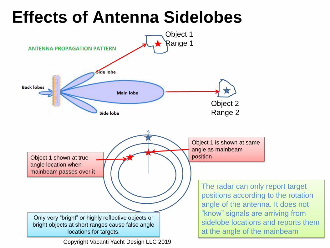
Effects of Antenna Sidelobes Object 1
Range 1
Object 2
Range 2
Object 1 is shown at same
angle as mainbeam
position Object 1 shown at true
angle location when
mainbeam passes over it
The radar can only report target
positions according to the rotation
angle of the antenna. It does not
“know” signals are arriving from
sidelobe locations and reports them
at the angle of the mainbeam
Only very “bright” or highly reflective objects or
bright objects at short ranges cause false angle
locations for targets.
Copyright Vacanti Yacht Design LLC 2019

Examples of “Sidelobes” in Light Illumination
Sidelobe examples Mainbeam examples
Copyright Vacanti Yacht Design LLC 2019

Sidelobe Detection Example
Sidelobe
detection of
bright object
on shore.
Antenna
location is
blue line –
sidelobe
location is
dashed red
line
Sidelobe Detections Copyright Vacanti Yacht Design LLC 2019

Safe and Effective Radar Installation Radar is LINE OF SIGHT – ANY Obstruction in the path of the antenna will
result in some form of degraded performance
Mounting Position
Highest Possible on the vessel with 360 degree clear line of sight
Sailboat installations are always limited by Mast
High Power Magnetron Radars MUST be mounted ABOVE height of all
crew positions
Damage to eye sight can result from high power pulse radars
Least Possible Obstructions
No more obstruction than standard “mast” mounting if at all possible
Install well above a Bimini with metal supports
Do not place kayaks, dinghies, Crab pots or other gear in way of the
radar
NEVER install BELOW windscreen of Flybridge
Dangerous to crew
Severe obstruction to the side and aft directions
High Sidelobe levels with false target detections
Non-Line of sight to GPS Antennas
High Power Radar Microwave Radiation may cause damage to GPS
receiver in the antenna module
Radar radiation may jam or cause intermittent operation of GPS receiver
Copyright Vacanti Yacht Design LLC 2019

Do’s and Don’ts for Radar Installation
As installed new by the
builder! What were they
thinking? Green: Clear of obstructions and away
from people to prevent exposure to harmful
microwave radiation
Orange: May cause interference with other
electronics or second radar
Red: Major obstructions and danger to
people from Microwave radiation
Copyright Vacanti Yacht Design LLC 2019

Example System Integration
Wind Display
@
Helm
Satellite
Antenna
Satellite
Receiver
Depth
Sounder
Ethernet Switch
Camera Display
at
Flybridge
Quantum
Radar
Auto
pilot
Auto
Pilot
Computer
Heading
Sensor
AIS
Xponder
Rudder GPS
VHF 1
VHF 2
Ray STNG /
NMEA 2000 Bus NMEA 0183 Bus
GPS Location Fusion
Stereo VHF Radios may provide AIS
receive only or transponder
capability that can be sent to other
systems via NMEA bus systems
Dedicated AIS
Transponder
Copyright Vacanti Yacht Design LLC 2019

Two Forms of Radar Display / Control
Dedicated Radar Display
Multi-Function Display – Chart Overlay
or Dedicated View
Copyright Vacanti Yacht Design LLC 2019

Doppler Vs Standard Radar Standard Radar – No Doppler
Doppler
Approaching
Target
Doppler
Receding Target
Doppler capability is only possible with solid state
pulse compression or FMCW radar systems that
provide required frequency stability
Additional Signal processing is required to provide
measurement of target velocity and direction of
travel
Doppler immediately shows moving vessels in a
cluttered radar image
Overlay of AIS and Radar
Detection with AIS direction and
speed of travel shown graphically
Copyright Vacanti Yacht Design LLC 2019

Multiple Vessel Crossing Situation
• Radar and AIS
Targets
• AIS Vs Radar
• Barge
• Antenna
Sidelobes
Note that the presence of a
barge is NOT provided by
AIS – it can only be seen by
radar!!
Non AIS
equipped
trawler
Copyright Vacanti Yacht Design LLC 2019
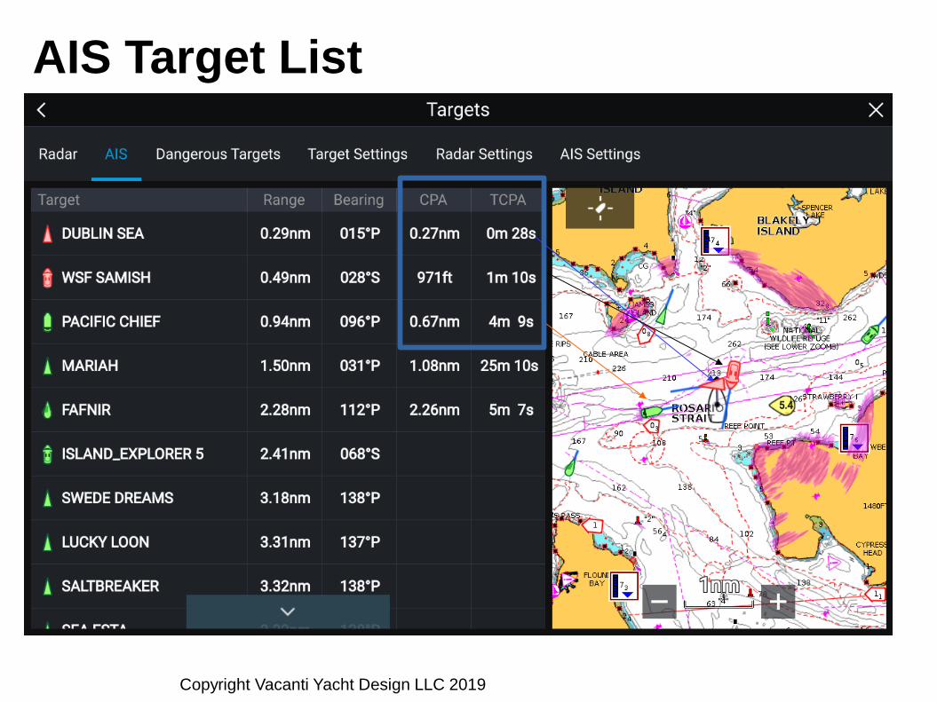
AIS Target List
Copyright Vacanti Yacht Design LLC 2019

New Collision Avoidance Graphics for Radar
Settings for Automated Collision
Avoidance for Radar Targets
Copyright Vacanti Yacht Design LLC 2019

Collision Avoidance Example
1
2 3
4
History of
target Motion Beginning of
Track
TCPA = Time to
Closest Point of
Approach
Copyright Vacanti Yacht Design LLC 2019

Radar Track Vector of Nearby Vessel
Radar detection and
estimate of speed
and direction of
travel using manual
detection and ARPA
ARPA = Automatic Radar Plotting Aid – For Tracking Targets Copyright Vacanti Yacht Design LLC 2019

Close Up of Tracked ARPA Target and Shoreline
Radar
Reflection is
blocked by
Armitage
Island
Tracked Target with 3 minute Direction and position vector Copyright Vacanti Yacht Design LLC 2019

Vessels in Harney Channel
Two vessel
detections, currently
not being tracked
Copyright Vacanti Yacht Design LLC 2019

A few minutes later
Copyright Vacanti Yacht Design LLC 2019

Approaching Vessel being Tracked
Copyright Vacanti Yacht Design LLC 2019

Track has been dropped
Copyright Vacanti Yacht Design LLC 2019

Target Crossing at 90 Degrees
Copyright Vacanti Yacht Design LLC 2019

Vessel approaching narrow channel
Copyright Vacanti Yacht Design LLC 2019

Target Intent??
Copyright Vacanti Yacht Design LLC 2019

RADAR Settings and Controls
Sea Clutter Sea Clutter is radar reflections from Wave Tops in Windy Conditions
Fixed Sea Clutter Settings
“Harbor”, “Coastal” and “Open Sea”
Variable Sea Clutter Control
Rain Attenuation Reduce wide area reflections from rain fall
Mitigates saturation of display by wide area reflections from rain fall
Receiver Gain Settings Allow selective detection of highly reflective or low reflectivity targets
Adjust overall sensitivity of the radar
Color Gain Settings Allows indication of Radar Reflectivity of Targets
Copyright Vacanti Yacht Design LLC 2019

Example of Sea Clutter on Radar Screen
Sea Clutter (Reflections from Wave
Tops) Overwhelms Sea Targets
Sea Clutter Reduction Via
Attenuation Setting
Copyright Vacanti Yacht Design LLC 2019

Preset Radar Sea Clutter Settings
“Harbor” “Coastal”
“Offshore”
• Harbor – Minimum Attenuation –
small targets are visible
• Coastal – Moderate Attenuation of
Sea Clutter, some targets are
removed
• Offshore – High Attenuation of Sea
Clutter, small targets are removed
Copyright Vacanti Yacht Design LLC 2019

Sea Clutter Reduction
“Offshore” Sea
Clutter Setting
48% Sea Clutter
Attenuation
0% Sea Clutter
Attenuation
Copyright Vacanti Yacht Design LLC 2019
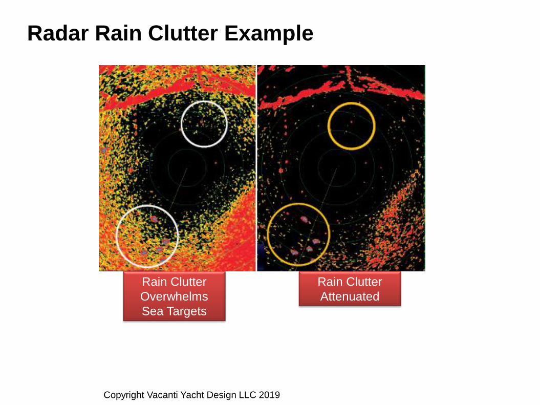
Radar Rain Clutter Example
Rain Clutter
Attenuated
Rain Clutter
Overwhelms
Sea Targets
Copyright Vacanti Yacht Design LLC 2019

Rain Clutter Adjustment
Zero Rain
Attenuation 51% Rain
Attenuation
84% Rain
Attenuation
Note Blue tracks of
targets that have
been lost with
added attenuation
for rain clutter
suppression
Blue detections are
“trails” or histories of
past detections. It is
also useful to indicate
the motion of a moving
target
Use Care when adding
rain clutter
suppression to avoid
losing too many
targets
Copyright Vacanti Yacht Design LLC 2019

Receiver Gain Adjustment
Normal
“auto” setting
Minimum
Receiver Gain
Maximum
Receiver Gain
Copyright Vacanti Yacht Design LLC 2019

What Radar Cannot or May Not Do Cannot see through or around obstacles
Causes “shadowing” or blank spots
Radar image will not directly correspond to shorelines
on a chart – making dedicated radar displays difficult to
use in many conditions
Chart Overlay is a big help in validating targets and
navigation position
Cannot see floating debris on the water
Cannot see small targets in heavy rain conditions
Rain attenuates signal and causes “display saturation”
Cannot see small targets in Heavy Seas
Reflections from waves obscure targets
Marine Radar may produce target “fading” in smooth
conditions
This is a physics phenomenon and not a short coming of
the radar itself. Continued motion of at least one vessel will
cause the target to eventually reappear Copyright Vacanti Yacht Design LLC 2019

Latest Radar / AIS / GPS Technology Automated On Screen Collision Avoidance Plotting
When engaged it provides direct information on how to steer or change speed
to avoid a collision or near collision
AIS – Aids to Navigation – Virtual Buoys that are not physically on the water but are
observed on electronic charts
Doppler Radar
Where radar is going:
Low power, transistor based radars with complex waveforms
Electronic Beam Steering with no mechanical rotation
High Speed updates, simultaneously observe 3 or 4 zones at the same
time
Doppler Processing to reduce sea clutter, enhance target detection
Automated collision avoidance capabilities
GPS Rollover Date April 6 2019!!!
Older (<2005) GPS Receivers or Chart Plotters may have problems with
GPS functionality. Check with your Manufacturer. Last Rollover was in 1999.
Copyright Vacanti Yacht Design LLC 2019

Summary and Suggestions Strongly Encourage installing AIS and Radar together
AIS Receive and display capability on your display allows calling a vessel on
Channels 13 or 16 By Name of Vessel – rather than “ Large vessel in San
Juan Channel heading north”
Encourage installing AIS Class B Transponder in addition to Radar
Helps make sure that commercial vessels can see you well in advance
A big help with avoiding Ferry, Tug, Ship and Transport Traffic
They know who you are and can see you on their commercial displays
AIS does NOT show barge Tows!!! Only Radar will show you that there are
TWO vessels involved and you MUST not pass astern of a tug with a tow!!
AIS does not show vessels that are not equipped with a transponder or
vessels with transponders turned off or in Silent mode
Navy and Coast Guard Vessels Frequently do NOT actively transmit on
AIS for security reasons
ONLY Radar will detect these large vessels in low visibility
conditions
Consider Upgrade to new Doppler Capable Radars
Automatically locates targets and shows Approaching or Receding motion with
no manual interaction with the radar
Very critical in foggy conditions with high speed fishing boats or dense
traffic areas
Copyright Vacanti Yacht Design LLC 2019