Rada 425R Installation and Maintenance - Armstrong Inc. · to Armstrong at the time the order ......
16
Rada ® 425R Installation and Maintenance Water Temperature Controls Recirculation Systems Thermostatic This Rada 425R Valve has been supplied for this application based upon information provided to Armstrong at the time the order was placed. This Rada 425R Valve is configured for use in a central pumped recirculation system and should be installed as per the drawing on Page 5. This Rada 425R Valve has not been designed to deliver tepid water to emergency fixtures. For further information, please call our technical department Toll Free at 1-888-HOT-HOSE. Model No. Rada 425R Serial No. Ship Date 1017 ALIB-425R-B B125
-
Upload
nguyenkhanh -
Category
Documents
-
view
214 -
download
0
Transcript of Rada 425R Installation and Maintenance - Armstrong Inc. · to Armstrong at the time the order ......

1
Rada® 425RInstallation and Maintenance
Water Temperature ControlsRecirculation Systems
Thermostatic
This Rada 425R Valve has been supplied for this application based upon information provided to Armstrong at the time the order was placed.
This Rada 425R Valve is configured for use in a central pumped recirculation system and should be installed as per the drawing on Page 5.
This Rada 425R Valve has not been designed to deliver tepid water to emergency fixtures.
For further information, please call our technical department Toll Free at 1-888-HOT-HOSE.
Model No. Rada 425R
Serial No.
Ship Date
1017
ALIB-425R-B
B125
2
Water Temperature Control - Recirculation Systems
Rada Thermostatic Mixing Valves (gpm)
ModelPressure Drop (psi) Min. System
Draw-offMaximum Flow
@7.5ft/sec. (2.3 m/s)C
v5 10 15 20
320R 8 11 13 15 0 11 3.4
425R 15 22 27 31 0 18 6.9
40R 36 51 62 72 0 41 16.0
50R 49 70 85 98 0 73 22.0
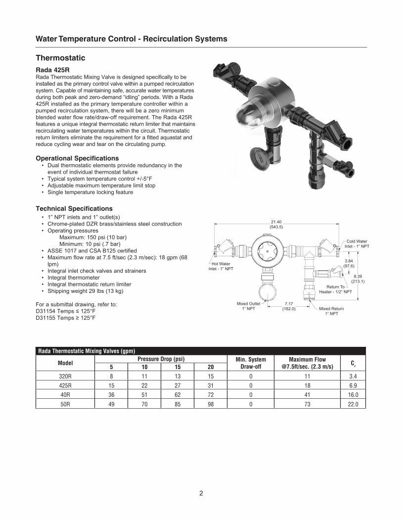
ThermostaticRada 425RRada Thermostatic Mixing Valve is designed specifically to be installed as the primary control valve within a pumped recirculation system. Capable of maintaining safe, accurate water temperatures during both peak and zero-demand “idling” periods. With a Rada 425R installed as the primary temperature controller within a pumped recirculation system, there will be a zero minimum blended water flow rate/draw-off requirement. The Rada 425R features a unique integral thermostatic return limiter that maintains recirculating water temperatures within the circuit. Thermostatic return limiters eliminate the requirement for a fitted aquastat and reduce cycling wear and tear on the circulating pump.
Operational Specifications• Dual thermostatic elements provide redundancy in the
event of individual thermostat failure• Typical system temperature control +/-5°F• Adjustable maximum temperature limit stop• Single temperature locking feature
Technical Specifications • 1” NPT inlets and 1” outlet(s)• Chrome-plated DZR brass/stainless steel construction• Operating pressures
Maximum: 150 psi (10 bar) Minimum: 10 psi (.7 bar)• ASSE 1017 and CSA B125 certified • Maximum flow rate at 7.5 ft/sec (2.3 m/sec): 18 gpm (68
lpm)• Integral inlet check valves and strainers• Integral thermometer• Integral thermostatic return limiter• Shipping weight 29 lbs (13 kg)
For a submittal drawing, refer to:D31154Temps≤125°FD31155Temps≥125°F
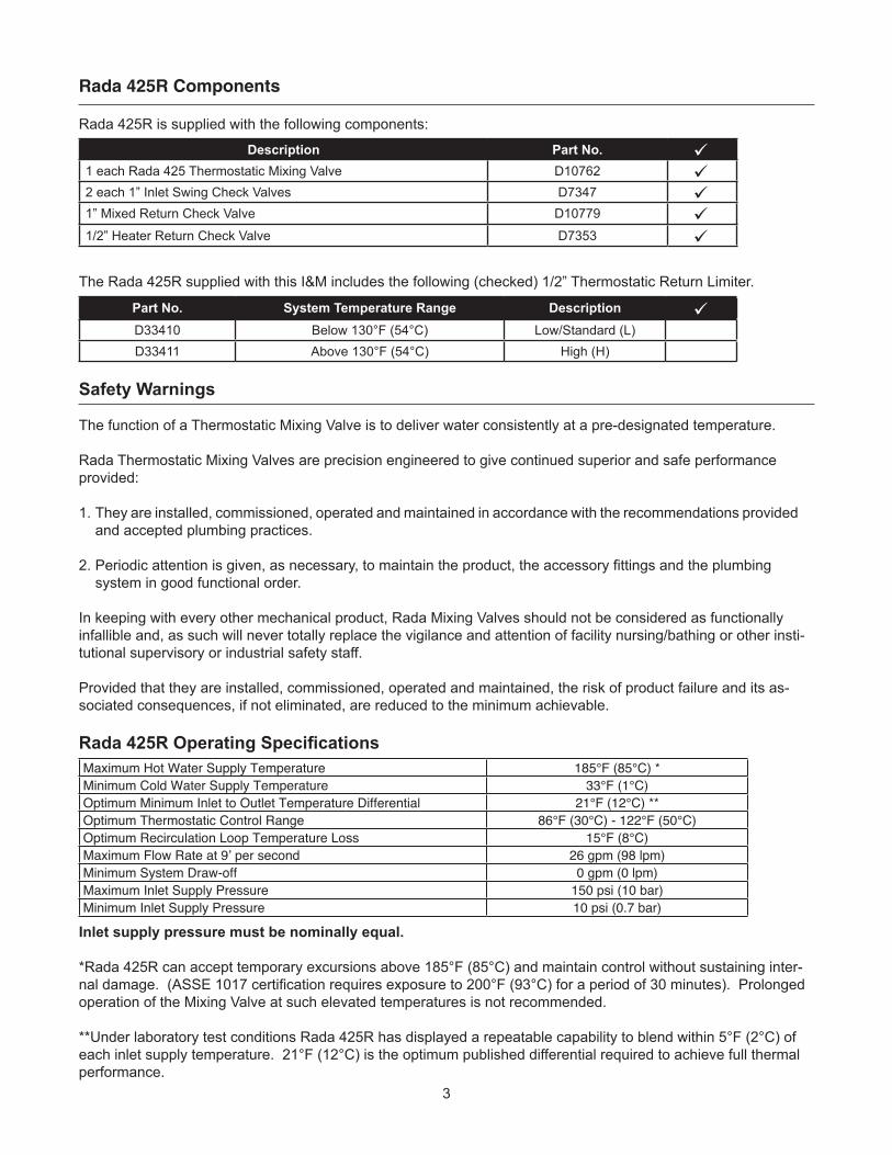
3.84(97.6)
7.17(182.0)
21.40(543.5)
8.39(213.1)
Return ToHeater - 1/2” NPT
Mixed Return1” NPT
Cold WaterInlet - 1” NPT
Hot WaterInlet - 1” NPT
Mixed Outlet1” NPT
3
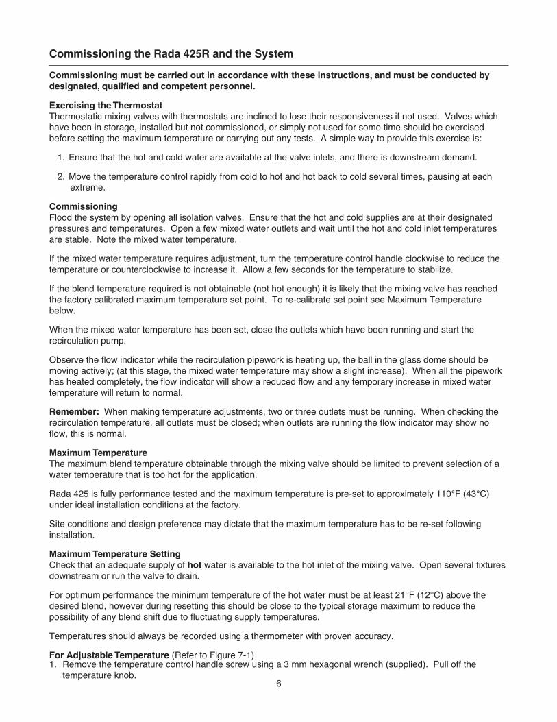
Rada 425R Components
Rada 425R is supplied with the following components:
The Rada 425R supplied with this I&M includes the following (checked) 1/2” Thermostatic Return Limiter.
Safety Warnings
The function of a Thermostatic Mixing Valve is to deliver water consistently at a pre-designated temperature.
Rada Thermostatic Mixing Valves are precision engineered to give continued superior and safe performance provided:
1. They are installed, commissioned, operated and maintained in accordance with the recommendations provided and accepted plumbing practices.
2.Periodicattentionisgiven,asnecessary,tomaintaintheproduct,theaccessoryfittingsandtheplumbing system in good functional order.
In keeping with every other mechanical product, Rada Mixing Valves should not be considered as functionally infallible and, as such will never totally replace the vigilance and attention of facility nursing/bathing or other insti-tutional supervisory or industrial safety staff.
Provided that they are installed, commissioned, operated and maintained, the risk of product failure and its as-sociated consequences, if not eliminated, are reduced to the minimum achievable.
Rada 425R Operating Specifications
Inlet supply pressure must be nominally equal.
*Rada 425R can accept temporary excursions above 185°F (85°C) and maintain control without sustaining inter-naldamage.(ASSE1017certificationrequiresexposureto200°F(93°C)foraperiodof30minutes).Prolongedoperation of the Mixing Valve at such elevated temperatures is not recommended.
**Under laboratory test conditions Rada 425R has displayed a repeatable capability to blend within 5°F (2°C) of each inlet supply temperature. 21°F (12°C) is the optimum published differential required to achieve full thermal performance.
Maximum Hot Water Supply Temperature 185°F (85°C) *Minimum Cold Water Supply Temperature 33°F (1°C) Optimum Minimum Inlet to Outlet Temperature Differential 21°F (12°C) **Optimum Thermostatic Control Range 86°F (30°C) - 122°F (50°C)Optimum Recirculation Loop Temperature Loss 15°F (8°C)Maximum Flow Rate at 9’ per second 26 gpm (98 lpm)Minimum System Draw-off 0 gpm (0 lpm)Maximum Inlet Supply Pressure 150 psi (10 bar)Minimum Inlet Supply Pressure 10 psi (0.7 bar)
Description Part No.1 each Rada 425 Thermostatic Mixing Valve D107622 each 1” Inlet Swing Check Valves D73471” Mixed Return Check Valve D10779
1/2” Heater Return Check Valve D7353
Part No. System Temperature Range DescriptionD33410 Below 130°F (54°C) Low/Standard (L)D33411 Above 130°F (54°C) High (H)

4
The Rada 425R Thermostatic Mixing Valve must be installed per the piping schematic provided on Page 5. Failure to follow this directive will compromise valve/system performance, void all warranties and may create a user comfort issue and safety concern.
Armstrong has Rada technical support personnel available from 8:00 a.m. to 5:00 p.m. EST. Call Toll Free 1-888-HOT-HOSE.
Notes:1. Rada 425R may be installed in a vertical or horizontal position, however, the check valves and flow indicator
are affected by gravity and must be oriented in a horizontal plane.
2. Rada 425R must be installed in a standard HOT-LEFT/COLD-RIGHT inlet supply configuration. There are red (hot) and blue (cold) markings on each valve. Rada 425R is provided as standard with a bottom outlet and a plugged top outlet. This configuration can be reversed by simply switching the outlet plug and fittings. The inlet supplies must always match the corresponding inlet ports on the valve.
3. Be sure to thoroughly flush the pipework before fitting the Rada 425R.
4. Be sure to make up all “sweat” or “soldered” fittings ahead of time. Do not expose Rada 425R or any of its fittings to extreme temperatures (such as a acetylene or propane torch).
5. Rada 425R is serviced from the front of the valve as you face it. A minimum 18” clearance in front of the Temperature Control Handle is suggested for internal parts access.
6. Rada 425R is pre-set at the factory to a fixed outlet temperature of 110°F (43°C). It is highly unlikely that the installation site conditions will match the test conditions. As such:
RADA 425R MUST BE RE-SET ON SITE BY QUALIFIED PERSONNEL.Rada 425R set up (commissioning the Rada 425R and the system) protocol is included on Page 6.
Rada 425R Installation
Operation
For models with a standard temperature knob fitted, adjustment of the blend temperature from preset maximum to cold is achieved by clockwise rotation of the knob.
Counterclockwise Hotter to Maximum Temperature Stop*
ClockwiseCooler
Single TemperatureLocked* No Movement
*Maximum temperature stop or single temperature locking feature is established during the on-site commissioning protocol referenced on page 6.

5
Rada 425R Recirculation System Schematic
Ther
mom
eter
Tem
p Li
mite
r
In-L
ine
Che
ckVa
lve
Sw
ing
Che
ckVa
lve
*
* O
rient
ed fo
r pip
ing
sche
mat
ic d
etai
l onl
y.
Mus
t be
inst
alle
d in
hor
izon
tal p
lane
.
Rec
ircul
atio
n P
ump
Che
ckVa
lve
Isol
atio
nVa
lve
Sto
pVa
lve
Stra
iner
6
Commissioning must be carried out in accordance with these instructions, and must be conducted by designated, qualified and competent personnel.
Exercising the ThermostatThermostatic mixing valves with thermostats are inclined to lose their responsiveness if not used. Valves which have been in storage, installed but not commissioned, or simply not used for some time should be exercised before setting the maximum temperature or carrying out any tests. A simple way to provide this exercise is: 1. Ensure that the hot and cold water are available at the valve inlets, and there is downstream demand.
2. Move the temperature control rapidly from cold to hot and hot back to cold several times, pausing at each extreme.
CommissioningFlood the system by opening all isolation valves. Ensure that the hot and cold supplies are at their designated pressures and temperatures. Open a few mixed water outlets and wait until the hot and cold inlet temperatures are stable. Note the mixed water temperature.
If the mixed water temperature requires adjustment, turn the temperature control handle clockwise to reduce the temperature or counterclockwise to increase it. Allow a few seconds for the temperature to stabilize.
If the blend temperature required is not obtainable (not hot enough) it is likely that the mixing valve has reached the factory calibrated maximum temperature set point. To re-calibrate set point see Maximum Temperature below.
When the mixed water temperature has been set, close the outlets which have been running and start the recirculation pump.
Observe the flow indicator while the recirculation pipework is heating up, the ball in the glass dome should be moving actively; (at this stage, the mixed water temperature may show a slight increase). When all the pipework has heated completely, the flow indicator will show a reduced flow and any temporary increase in mixed water temperature will return to normal.
Remember: When making temperature adjustments, two or three outlets must be running. When checking the recirculation temperature, all outlets must be closed; when outlets are running the flow indicator may show no flow, this is normal.
Maximum Temperature The maximum blend temperature obtainable through the mixing valve should be limited to prevent selection of a water temperature that is too hot for the application.
Rada 425 is fully performance tested and the maximum temperature is pre-set to approximately 110°F (43°C) under ideal installation conditions at the factory.
Site conditions and design preference may dictate that the maximum temperature has to be re-set following installation.
Maximum Temperature SettingCheck that an adequate supply of hot water is available to the hot inlet of the mixing valve. Open several fixtures downstream or run the valve to drain.
For optimum performance the minimum temperature of the hot water must be at least 21°F (12°C) above the desired blend, however during resetting this should be close to the typical storage maximum to reduce the possibility of any blend shift due to fluctuating supply temperatures.
Temperatures should always be recorded using a thermometer with proven accuracy.
For Adjustable Temperature (Refer to Figure 7-1)1. Remove the temperature control handle screw using a 3 mm hexagonal wrench (supplied). Pull off the temperature knob.
Commissioning the Rada 425R and the System

7
2. Remove the brass hub assembly.
3. Invert the hub 180° and use it to rotate the spindle until the desired maximum temperature is obtained at outlet point (clockwise=decrease temperature, counterclockwise=increase temperature). When resistance is felt do not use force to turn any further, as this can damage the internal components.
4. Once the desired maximum blend temperature is achieved, gently remove the hub without disturbing the spindle. Invert hub 180°, and re-position over the spindle so that the left stop lug on the hub rests against the right side of the stop on the valve body thus preventing any further counterclockwise rotation.
5. Re-fit the Temperature Control Handle.
For Locked Temperature (Refer to Figure 7-1)1. Remove the temperature control handle screw using a 3 mm hexagonal wrench (supplied). Pull off the
temperature knob.
2. Remove the brass hub assembly.
3. Invert the hub 180° and use it to rotate the spindle until the desired maximum temperature is obtained at outlet point (clockwise=decrease temperature, counterclockwise=increase temperature). When resistance is felt do not use force to turn any further, as this can damage the internal components.
4. Gently remove the hub without disturbing the spindle. Invert hub 180° and re-position over the spindle so that the two stop lugs on the bass hub “straddle” the stop on the valve body thus preventing any further rotation in either direction.
5. Re-fit the Temperature Control Handle.
Temperature Knob
Screw
HubStopLugs
Note position of brass stop
Commissioning - Adjustable Temperature Setting
Commissioning - Locked Temperature Setting
TemperatureKnob
StopLugs
Hub
Screw
Figure 7-1.

8
Rada 425R Servicing and Maintenance
Rada 425R Thermostatic Mixing Valves should be inspected annually, or more frequently where acknowledged site conditions such as high mineral content water dictate.
Rada 425R can be completely serviced from the front/top and all of the internal components are replaceable. To access the valves internal components for inspection, cleaning or replacement proceed as follows.
Maintenance must be carried out in accordance with these instructions, and must be conducted by designated, qualified and competent personnel. This mixing valve is designed for minimal maintenance under conditions of normal use. External surfaces may be wiped clean with a soft cloth, and if necessary, a mild detergent or soap solution can be used.
Warning! Many household and industrial cleaning products contain mild abrasives and chemical concentrates, and should not be used on polished, chromed or plastic surfaces.
Components are precision-made, so care must be taken while servicing to avoid damage.
Lubricant
Important! All seals are pre-lubricated. If you need to further lubricate the seals, use only a small amount of silicone-only based lubricants on this product. Do not use oil-based or other lubricant types as these may cause rapid deterioration of seals.
Maintenance Procedure1. Isolate/by-pass the valve by turning off each inlet supply, the outlet and the return line.
2. Use the 3 mm hexagonal wrench (supplied) to remove the temperature knob screw. Remove the temperature knob.
3. Loosen the two screws holding the cover shroud in position, turn clockwise and remove the cover shroud.
4. Remove the hub, the circlip and the pressure washer.
5. Remove the eight screws and remove the cover. Note the position of the stop on the cover, so that it can be reassembled in the same position.
6. Remove the temperature spindle and drive nut from the cover.
7. Remove the thermostat assembly and pinned actuator (inside port sleeve).
8. Remove the four retaining screws located on the flange around the shuttle sleeve (see Figure 8-1).
Figure 8-1.Isolator Valve
ThermostatAssembly
Port Sleeve
Drive Nut
TemperatureSpindle
Cover
Pressure Washer
Circlip
Hub
TemperatureKnob
Cover Shroud
Port SleeveRetaining Screw

9
9. Insert a bar (maximum of 6 mm diameter) through the holes provided at the front of the port sleeve and use this with a slight twisting action to carefully pull the shuttle assembly out of the body. (See Figure 9-1)
10. Remove both port sleeve screens by releasing the folded tabs. (See Figure 9-2)
11. To dismantle the port sleeve assembly, again insert the bar through the holes at the front of the port sleeve to hold the assembly while the retaining cap is loosened using a wrench (50 mm) across the flats. (See Figure 9-1)
There is spring tension behind the retaining cap, so completely unscrew and remove by hand.
Figure 9-1.
PortSleeve Assembly
RetainingCap
50 mmWrench
Bar(Max. 6 mm)
Figure 9-2.
Port SleeveAssembly
ShuttlePort SleeveScreens
Push out shuttle from this end
Retaining Cap
Overload Spring
ShuttleSeat
Return Spring
12. Lift out the overload spring and return spring and carefully push out the shuttle seat and shuttle (refer to Figure 9-2).
Cleaning/Replacement of Parts
13. The interior surface of the mixing valve body must be clean before refitting any parts. Rinse the valve interior thoroughly in clean water to remove any debris.
Note: The body interior must be cleaned carefully and not damaged in any way. Do not use any abrasive material.
14. Renew all O-Seals. Clean seal grooves taking care not to damage them or the seat.
15. Internal parts (with the exception of the Thermostat Assembly) can be cleaned using a mild proprietary inhibited scale solvent. After removing the scale, always rinse parts thoroughly in clean water before refitting.
Note: The body interior must be cleaned carefully and not damaged in any way. Do not use any abrasive material.
16. Lightly smear all seals and threads with a silicone-only based lubricant to assist
re-assembling.
17. Inspect the thermostat assembly for signs of damage.
18. Examine the shuttle seat, the shuttle and the port sleeve for signs of damage or corrosion; renew as necessary.
Re-Assembly
19. Insert the shuttle fully into the port sleeve (wider open end) with radius centre facing inwards (refer to Figure 10-1), ensuring that the separator seal remains in place and is not damaged.
Reference Figure 9-2
20. Insert shuttle seat into the port sleeve, ensuring that the cut-outs locate into the webs in the shuttle.
21. Insert the return spring through the centre of the overload spring. Insert both springs into the shuttle seat rear face.

10
Shuttle
Port SleeveAssembly
Figure 10-1.
22. Locate the retaining cap over the springs, compress and screw the cap fully into the port sleeve, ensuring that the threads are correctly engaged.
23. Replace the port sleeve screens, positioning the joint against one of the two solid sections. This will prevent debris from entering through the slot in the screen.
Reference Figure 8-1
24. Insert the port sleeve assembly into the valve body and secure in position with the four screws.
25. Insert the pinned actuator into the shuttle assembly.
26. Install the drive nut and temperature spindle into the cover. Note: The drive nut will need to be aligned with the grooves inside the cover.
27. Insert the thermostat into the drive nut.
28. Install new O-Seal and fit the cover, ensuring the end of the thermostat locates correctly into the drive nut. Rotate the cover so that it is positioned in the same position as it was when you removed it. Secure the cover in position with the eight screws.
29. Fit the pressure washer and secure in position with the circlip. Make sure that the circlip locates correctly in the groove in the temperature spindle.
30. Before fitting the hub, the temperature will need resetting; refer to Commissioning on page 6.
31. Fit the temperature knob and secure with the screw.

11
Rada 425R Parts List
E
EB, G
B
D33415D33416
F
D33390
E
D33414
D33417
D33412
D33413
G
D33419
E
G
D33425D33424
FF
F
G
G
G
D
D
G
Part No. DescriptionD33390 Knob Pack with ScrewD33412 Backplate PackD33413 Drain PlugD33414 CoverD33415 Cover ShroudD33416 Hub PackD33417 Thermostat PackD33418 DriveMechanismPack-componentsidentified“B”D33419 Port Sleeve AssemblyD33420 ShuttlePack-componentsidentified“D”D33421 CoverScrewPack-componentsidentified“E”D33422 FixingScrewPack-componentsidentified“F”D33423 O-SealPack-componentsidentified“G”D33424 NPT Inlet (Each)D33425 NPT Outlet ( Each )
D33426
Critical Component Pack consists of: D33417 Thermostat Pack D33420 Shuttle Pack D33423 O-Seal Pack
Part No. DescriptionD33410 1/2” Therm. Return Limiter < 125°FD33411 1/2” Therm. Return Limiter > 126°FD7353 1/2” Check Valve (return line to heater)
D10779 1” Check Valve (return line to TMV)D7347 1” Horizontal Check Valve (each)
D7347 D7347
D10779
D33411D33410
D7353D14049

12
Fitting or Replacing the Return Limiter (Part No. D33410/D33411)
When fitting a new return limiter, make sure that its working temperature is correct for the application/system.
Tighten the limiter body in place using hand pressure only, the rubber washer will make the seal. Over-tightening with a wrench may cause damage.
Use a wrench to hold back on limiter when fitting or removing from downstream pipework/fittings. Use two wrenches so that torque is not transmitted through the limiter body.
Note: Replacement ball flow indicator sight glass, indicator ball, clamping ring and seals are available separately.
Ensure that the glass dome on the flow indicator is positioned vertically upwards. Note direction of flow.
Rubber Seal
Return Limiter
IdentificationStamp (L or H)
ReturnLimiter
Return toHeater
Mixed Return
D7353D33410D33411
D10779
Use two wrenches totighten this coupling
Assemble LimiterHand-Tighten Only

13
Fault DiagnosisSymptom Cause Action
1. Only hot or cold water from outlet when mixed water is being used.
a. Inlet supplies reversed (i.e.: hot to cold or vice-versa).
Check-Rectify.Note:Rada425Risdifficulttoplumbwith reversed lines due to the location of the integral mixed water return pipe work which must return to the cold side of the valve. If suspicion persists check rear of valve under polymer mounting plate for raised “H” (hot) on appropriate inlet. If sight evaluation is not possible consult factory Technical Support for additional diagnostic tips.
b. No hot water available from hot water source. Check-Rectify.
c.Screens/filtersoccludedorinletsupplyfittingsplugged.
Refer to Servicing/Maintenance on Page 8 and 9. Figure 9-2 Rectify.
d. Refer to Symptom 4 below. Refer to Symptom 4 below.
e. Proportioning mechanism (shuttle) trapped against hot/cold seat.
RefertoServicing/MaintenanceonPage8.Atfigure8-1 place thumb into port sleeve and depress. Shuttle should move and spring back when pressure is relieved.
2.NoflowfromMixingValve outlet.
a. Hot or Cold inlet supply failure; Thermostat holding correct shutdown function.
Check-Rectify.
b.Screens/filtersblockedorinletsupplyfittingsplugged.
Refer to Servicing/Maintenance on Page 8 and 9. Figure 9-2 Rectify.
c. Mixing valve has not been commissioned correctly and proportioning mechanism (shuttle) is located against cold seat preventingre-circulationflow.
Refer to Page 4 and turn handle counterclockwise untilflowcommences.
3. Mixed water temperature at TMV outletfluctuatesanddoes not respond to adjustment.
a. Thermostat not operating correctly. Refer to Servicing/Maintenance on Page 8- Rectify.b. Return limiter not functioning correctly. Check that return limiter is functional.c. Un-equal inlet supply pressures. Check-Rectify.d.Inletsupplypressuresfluctuatingbeyond
valves capability to correct. Check-Rectify.
e.Hotwatersupplytemperaturefluctuatingbeyond valves capability to correct.
Check by carefully sensing inlet hot supply pipe work-rectify.
f.Partiallyoccludedscreens/filtersorpartiallyblockedinletfittings.
Refer to Servicing/Maintenance on Page 8 and 9. Figure 9-2 Rectify.
4. Hot water in cold supply and vice-versa.
a. Indicates non-functioning check valve (s). Diagnosebyturningoffmixedwateroutletflowand pump and check to see if inlet hot pipe work becomes cold and vice-versa.
5. Mixed water temperature too high when mixed water is being used.
a. Mixing Valve has not been commissioned correctly and set too high. Refer to Commissioning on Page 6 - Rectify.
b. Mixing Valve has not been commissioned correctly and was set when the hot supply temperature was too low.
Refer to Commissioning on Page 6 - Rectify.
c. Hot water is migrating into cold supply. See Item 4 above.d. Thermostat not operating correctly. Refer to Servicing/Maintenance on Page 8 - Rectify.
6. Mixed water temperature increases when no mixed water is being used (re-circulation system is under pump only demand).
a. Return limiter not operating correctly. Replace Return Limiter.

14
Fault Diagnosis
Symptom Cause Action7. Mixed water
temperature too low when mixed water is being used.
a. Mixing Valve has not been commissioned correctly and is set too low. Refer to Commissioning on Page 6 - Rectify.
b. Hot water heater is not keeping up with demand. Check-Rectify.
8. Mixed water temperature too low when no mixed water is being used (re- circulation system is under pump only demand).
a. Re-circulation has failed due to pump malfunction or system air locking. Check-Rectify.
b. Pump too small to adequately distribute water.
Refer to a trained and appropriate authority for system sizing assistance.
c. See Item 7a above.
9.Mixedwaterflowrate is reduced when mixed water is being used.
a.Partiallyoccludedinletscreens/filtersorpartiallyblockedinletfittings. Refer to Servicing/Maintenance on Page 8 - Rectify.
b. Inlet supply pressure has fallen. Check-Rectify.c. Accumulated pressure losses within the
system are too high.Refer to a trained and appropriate authority for system sizing assistance.
d. Additional demand has been placed on system.
Refer to a trained and appropriate authority for system sizing assistance.
10. Water leaking from valve body. a. Seals worn or damaged.
Obtain Seal Pack (D33423) and renew all seals. Note: If leak from around temperature spindle persists renew Drive Mechanism Pack (D33418).

15
Notes
16
Armstrong International221 Armstrong Blvd., Three Rivers, Michigan 49093 - USAPh: (269) 279-3602 Toll Free: (888) HOT-HOSE (468-4673) Fax: (269) 279-3130
ALIB-425R-BRada 425R
Printed in U.S.A. - 7/12© 2012 Armstrong International, Inc.
Designs, materials, weights and performance ratings are approximate and subject to change without notice.Visit armstronginternational.com for up-to-date information.
Limited Warranty and RemedyArmstrongHotWaterGroup,Inc.(“Armstrong”)warrantstotheoriginaluserofthoseproductssuppliedbyitandused in the service and in the manner for which they are intended, that such products shall be free from defects in material and workmanship for a period of one (1) year from the date of installation, but not longer than 15 months from the date of shipment from the factory [unless a Special Warranty Period applies, as listed below]. This warranty does not extend to any product that has been subject to misuse, neglect, or alteration after shipment from the Armstrong factory. Except as may be expressly provided in a written agreement between Armstrong and the user, which is signed by both parties, Armstrong DOES NOT MAKE ANY OTHER REPRESENTATIONS OR WARRANTIES, EXPRESS OR IMPLIED, INCLUDING, BUT NOT LIMITED TO, ANY IMPLIED WARRANTY OF MERCHANTABILITY OR ANY IMPLIED WARRANTY OF FITNESS FOR A PARTICULAR PURPOSE. The sole and exclusive remedy with respect to the above limited warranty or with respect to any other claim relating to the products or to defects or any condition or use of the products supplied by Armstrong, however caused, and whether such claim is based upon warranty, contract, negligence, strict liability, or any other basis or theory, is limited to Armstrong’s repair or replacement of the part or product, excluding any labor or any other cost to remove or install said part or product, or, at Armstrong’s option, to repayment of the purchase price. As a condition of enforcing any rights or remedies relating to Armstrong products, notice of any warranty or other claim relating to the products must be given in writing to Armstrong: (i) within 30 days of last day of the applicable warranty period, or (ii) within 30 days of the date of the manifestation of the condition or occurrence giving rise to the claim, whichever is earlier. IN NO EVENT SHALL ARMSTRONG BE LIABLE FOR SPECIAL, DIRECT, INDIRECT, INCIDENTAL OR CONSEQUENTIAL DAMAGES, INCLUDING, BUT NOT LIMITED TO, LOSS OF USE OR PROFITS OR INTERRUPTION OF BUSINESS. The Limited Warranty and Remedy terms herein apply notwithstanding any contrary terms in any purchase order or form submitted or issued by any user, purchaser, or third party and all such contrary terms shall be deemed rejected by Armstrong.
Special Warranty Periods are as follows:
Flo-Direct Gas Fired Water HeaterThestainlesssteelstructureandstainlesssteelinternals(flame,tube,pallrings,supports,etc.)shallhave a ten (10) year non-prorated guarantee against burn out or any structural failure caused by materials and workmanship. Provided only clean potable water is heated. The other components on the Flo-Direct, such as valves, combustion equipment, electrical controls, and the burner shall have a two (2) year non-prorated guarantee against failure caused by materials and workmanship.
Flo-Rite-Temp Instantaneous Water HeaterThe tube bundle shall have a 10-year guarantee against failure caused by materials or workmanship provided by Armstrong but not against gasket failure or damage caused by corrosion, water hammer or lack of proper cleaning.
Flo-Rite-Temp Packaged Instantaneous Water HeaterTwo (2) years from the date of installation, but not longer than 27 months from the date of shipment. See above for tube bundle guarantee.
Flo-Eco High Efficiency Gas Water HeaterThe heat exchanger and supplied integral components such as the burner, the electrical controls and valving shall have a two (2) year warranty from the date of installation but no longer than 27 months from the date of shipment. The tank and replaceable tank liner shall have a 5 year warranty from the date of shipment.
The Brain – Model DRV80 and derivative assemblies shall have a 5-year all component parts warranty.