Računarska grafika GDI+ (Graphics Device Interface Plus)
43
Računarska grafika GDI+ (Graphics Device Interface Plus)
-
Upload
annabelle-manning -
Category
Documents
-
view
242 -
download
1
Transcript of Računarska grafika GDI+ (Graphics Device Interface Plus)
Računarska grafika
GDI+(Graphics Device Interface Plus)
Introduction
•Windows GDI+ is the portion of the Windows XP operating system or Windows Server 2003 operating system that provides two-dimensional vector graphics, imaging, and typography. GDI+ improves on Windows Graphics Device Interface (GDI) (the graphics device interface included with earlier versions of Windows) by adding new features and by optimizing existing features.
The namespaces in GDI+
•System.Drawing▫This is the core GDI+ namespace. It defines
objects for basic rendering (fonts, pens, basic brushes, etc.) and the most important object: Graphics.
•System.Drawing.Drawing2D▫This gives you objects for more advanced
two-dimensional vector graphics. Some of them are gradient brushes, pen caps, and geometric transforms.
The namespaces in GDI+
•System.Drawing.Imaging▫If you want to change graphical images -
that is, change the palette, extract image metadata, manipulate metafiles, and so forth - this is the one you need.
•System.Drawing.Printing▫To render images to the printed page,
interact with the printer itself, and format the overall appearance of a print job, use the objects here.
The namespaces in GDI+
•System.Drawing.Text▫You can use collections of fonts with this
namespace.
Graphics object
•The place to start with GDI+ is the Graphics object. Although the things you draw show up on your monitor or a printer, the Graphics object is the "canvas" that you draw on.
•Graphics object is always associated with a particular device context.
How do I get a Graphics object?•You can get Graphics object from other
objects. (e.g. event e parameter that is passed to the OnPaint event)
•You can use the CreateGraphicsmethod for a device context to create a Graphics object.
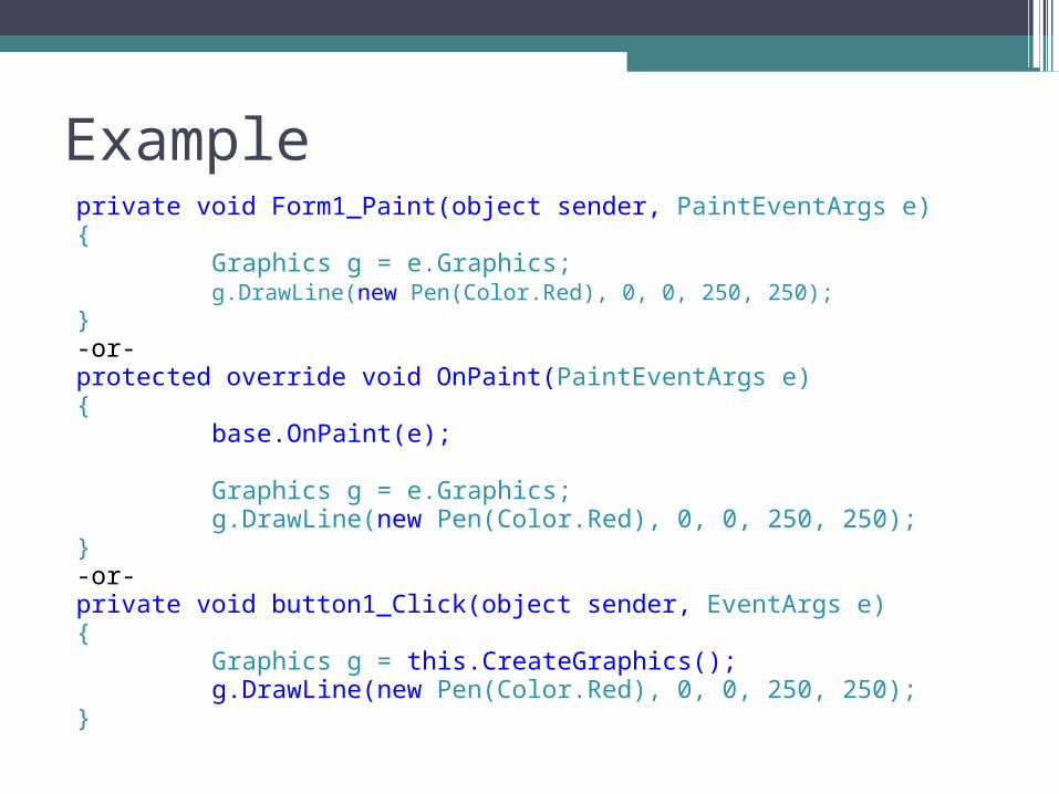
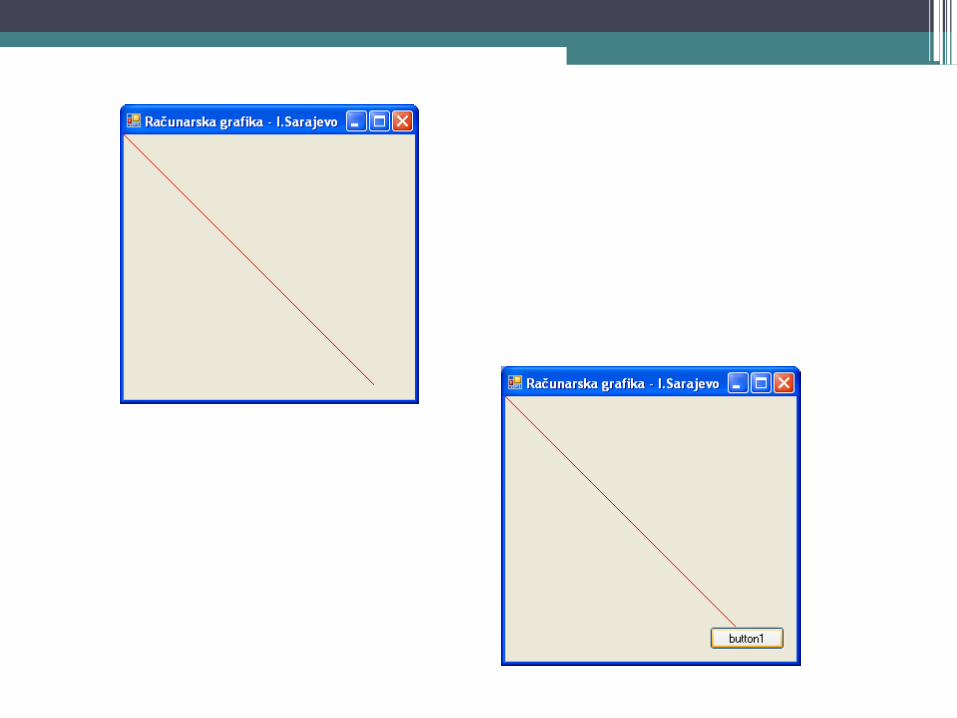
Exampleprivate void Form1_Paint(object sender, PaintEventArgs e){
Graphics g = e.Graphics;g.DrawLine(new Pen(Color.Red), 0, 0, 250, 250);
}-or-protected override void OnPaint(PaintEventArgs e){
base.OnPaint(e);
Graphics g = e.Graphics;g.DrawLine(new Pen(Color.Red), 0, 0, 250, 250);
}-or-private void button1_Click(object sender, EventArgs e){
Graphics g = this.CreateGraphics();g.DrawLine(new Pen(Color.Red), 0, 0, 250, 250);
}
Vector Graphics versus Bitmaps•"vector" is another word for a line, this
way of using GDI+ is often called vector graphics.
•The other major type of graphics is create graphics using individual points of color like your TV or computer monitor does it. This is called bitmap graphics and will be covered in a later segment.
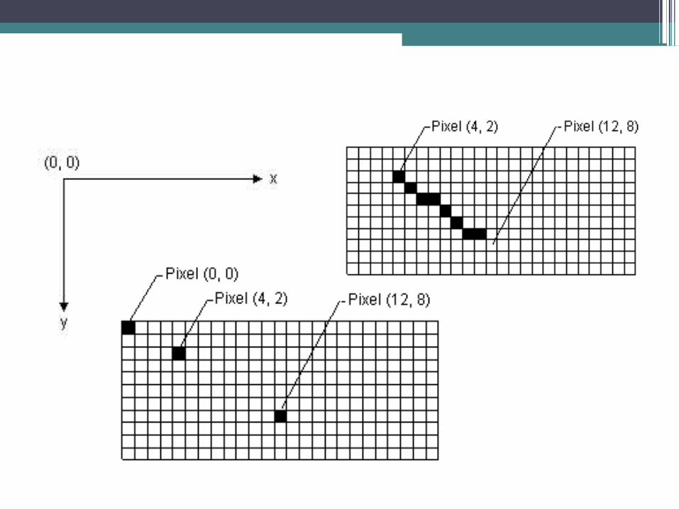

Coordinate spacesThere are three distinct coordinate spaces in GDI+. These are:• World coordinate space. This is where you put the coordinates
that define lines, shapes and points in the 2 dimensional space of the graphics system. World coordinates are abstract values expressed as floating point numbers. Essentially, whenever you draw something it goes into this coordinate space.
• Page Coordinate Space. The Page space is where the world coordinates are transformed into some real-world value. You can make the Page Space represent pixels, inches millimeters and so-on. This is what makes GDI+ a resolution independent system. You control how the page space interprets the world space by telling the Graphics object what PageUnit is being used and adjusting the PageScale.
• Device Coordinate Space. This space is controlled by the system and enables the real-world values in the Page Space to be translated to your screen or printer. Device space ensures that a 1 inch long line looks an inch long on the screen and on the printer even though the two devices may have very different pixel resolutions. You have no direct control over this space.
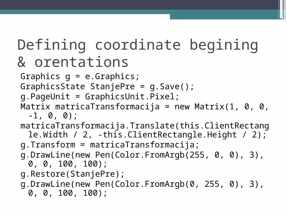
Defining coordinate begining & orentationsGraphics g = e.Graphics;GraphicsState StanjePre = g.Save();g.PageUnit = GraphicsUnit.Pixel;Matrix matricaTransformacija = new Matrix(1, 0, 0, -1, 0, 0);
matricaTransformacija.Translate(this.ClientRectangle.Width / 2, -this.ClientRectangle.Height / 2);
g.Transform = matricaTransformacija;g.DrawLine(new Pen(Color.FromArgb(255, 0, 0), 3), 0, 0, 100, 100);
g.Restore(StanjePre);g.DrawLine(new Pen(Color.FromArgb(0, 255, 0), 3), 0, 0, 100, 100);

Color
Color.FromArgb(255, 0, 0);Color.FromArgb(128, 255, 0, 0);Color.FromName("red");Color.FromKnownColor(KnownColor.Red);Color.Red;
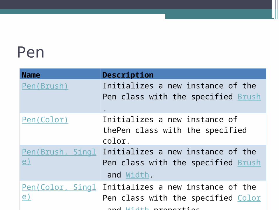
PenName DescriptionPen(Brush) Initializes a new instance of the Pen class with the
specified Brush.
Pen(Color) Initializes a new instance of thePen class with the specified color.
Pen(Brush, Single) Initializes a new instance of the Pen class with the specified Brush and Width.
Pen(Color, Single) Initializes a new instance of the Pen class with the specified Color and Width properties.
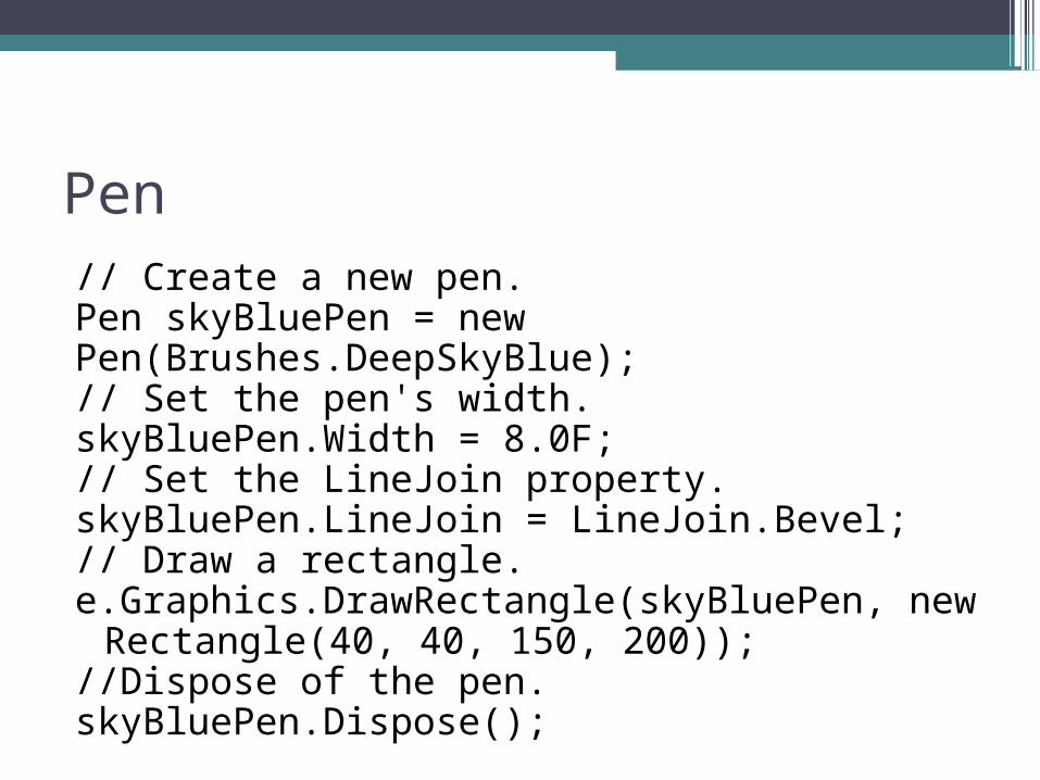
Pen// Create a new pen. Pen skyBluePen = newPen(Brushes.DeepSkyBlue); // Set the pen's width. skyBluePen.Width = 8.0F; // Set the LineJoin property. skyBluePen.LineJoin = LineJoin.Bevel; // Draw a rectangle.e.Graphics.DrawRectangle(skyBluePen, new
Rectangle(40, 40, 150, 200)); //Dispose of the pen. skyBluePen.Dispose();
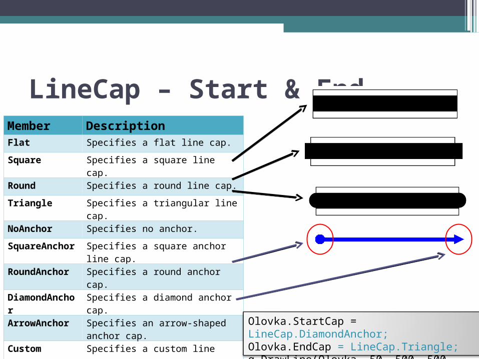
LineCap – Start & End Member DescriptionFlat Specifies a flat line cap.
Square Specifies a square line cap.
Round Specifies a round line cap.
Triangle Specifies a triangular line cap.
NoAnchor Specifies no anchor.
SquareAnchor Specifies a square anchor line cap.
RoundAnchor Specifies a round anchor cap.
DiamondAnchor Specifies a diamond anchor cap.
ArrowAnchor Specifies an arrow-shaped anchor cap.
Custom Specifies a custom line cap.
AnchorMask Specifies a mask used to check whether a line cap is an anchor cap.
Olovka.StartCap = LineCap.DiamondAnchor;Olovka.EndCap = LineCap.Triangle;g.DrawLine(Olovka, 50, 500, 500, 500);
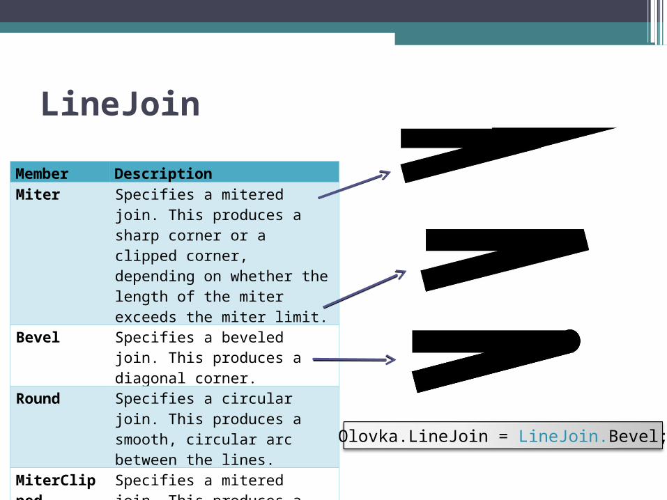
LineJoin
Member DescriptionMiter Specifies a mitered join. This
produces a sharp corner or a clipped corner, depending on whether the length of the miter exceeds the miter limit.
Bevel Specifies a beveled join. This produces a diagonal corner.
Round Specifies a circular join. This produces a smooth, circular arc between the lines.
MiterClipped Specifies a mitered join. This produces a sharp corner or a beveled corner, depending on whether the length of the miter exceeds the miter limit.
Olovka.LineJoin = LineJoin.Bevel;
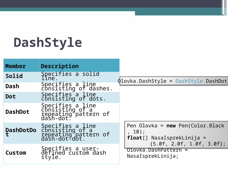
DashStyle
Member Description
Solid Specifies a solid line.
Dash Specifies a line consisting of dashes.
Dot Specifies a line consisting of dots.
DashDot Specifies a line consisting of a repeating pattern of dash-dot.
DashDotDotSpecifies a line consisting of a repeating pattern of dash-dot-dot.
Custom Specifies a user-defined custom dash style.
Pen Olovka = new Pen(Color.Black, 10);float[] NasaIsprekLinija =
{5.0f, 2.0f, 1.0f, 3.0f};Olovka.DashPattern = NasaIsprekLinija;
Olovka.DashStyle = DashStyle.DashDot;
Drawing basic shapes
To draw lines with Windows GDI+ you need to
create a Graphics object and a Pen object. The Graphics object provides the methods
that actually do the drawing, and the Pen object
stores attributes of the line, such as color, width,
and style.
Basic shapes• Lines• Rectangles• Ellipses • Arcs• Pies• Polygons• Cardinal Splines• Bézier Splines• Paths• Open and Closed Curves• Regions• Clipping
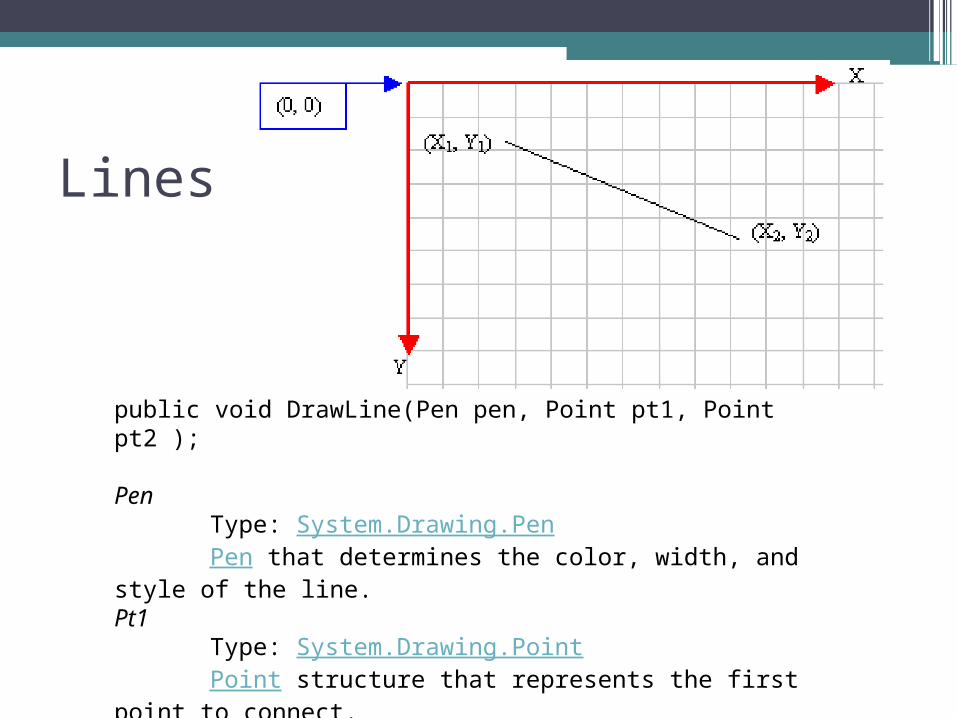
Lines
public void DrawLine(Pen pen, Point pt1, Point pt2 );
PenType: System.Drawing.PenPen that determines the color, width, and style of the
line.Pt1
Type: System.Drawing.PointPoint structure that represents the first point to
connect. Pt2
Type: System.Drawing.PointPoint structure that represents the second point to
connect.

Linesg.DrawLine(new Pen(Color.Red, 3.2f), 0, 0, 250, 250);
Point PocetnaTacka = new Point(0,0);Point KrajnjaTacka = new Point(250,50);Pen Olovka = new Pen(Color.GreenYellow, 3.2f);g.DrawLine(Olovka, PocetnaTacka, KrajnjaTacka);
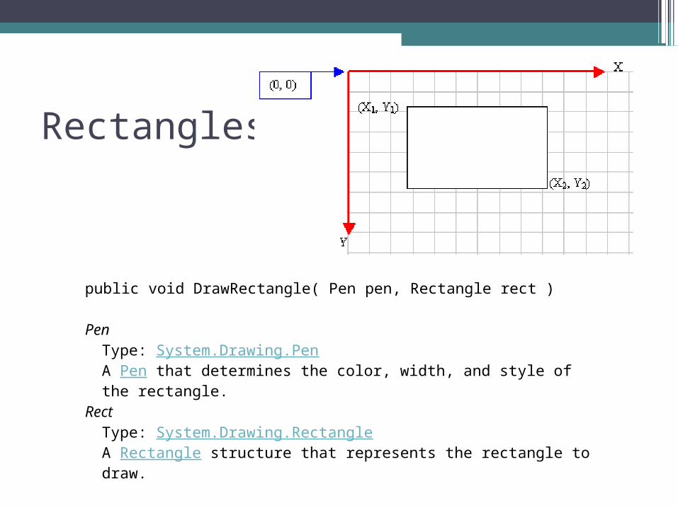
Rectangles
public void DrawRectangle( Pen pen, Rectangle rect )
PenType: System.Drawing.PenA Pen that determines the color, width, and style of the rectangle.
RectType: System.Drawing.RectangleA Rectangle structure that represents the rectangle to draw.
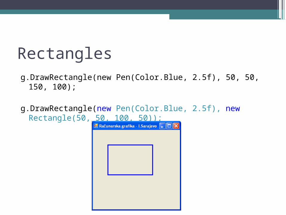
Rectanglesg.DrawRectangle(new Pen(Color.Blue, 2.5f), 50, 50, 150,
100);
g.DrawRectangle(new Pen(Color.Blue, 2.5f), new Rectangle(50, 50, 100, 50));
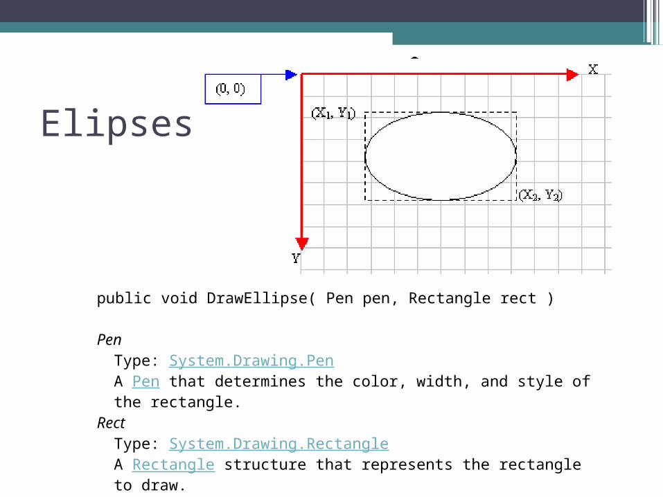
Elipses
public void DrawEllipse( Pen pen, Rectangle rect )
PenType: System.Drawing.PenA Pen that determines the color, width, and style of the rectangle.
RectType: System.Drawing.RectangleA Rectangle structure that represents the rectangle to draw.
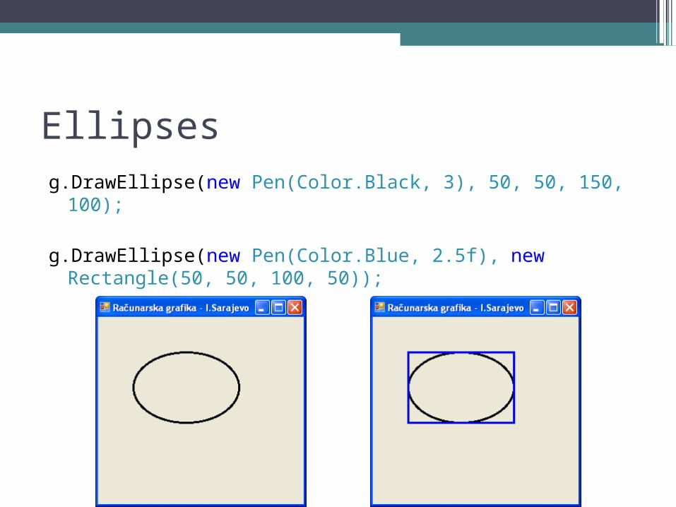
Ellipsesg.DrawEllipse(new Pen(Color.Black, 3), 50, 50, 150, 100);
g.DrawEllipse(new Pen(Color.Blue, 2.5f), new Rectangle(50, 50, 100, 50));
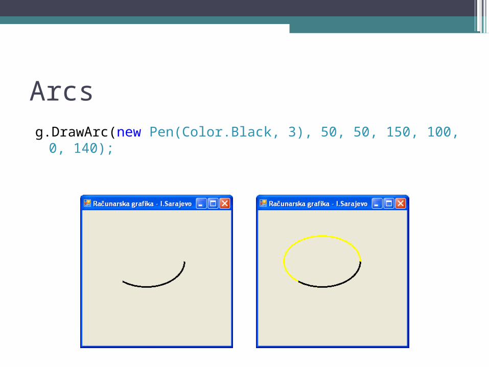
Arcsg.DrawArc(new Pen(Color.Black, 3), 50, 50, 150, 100, 0, 140);
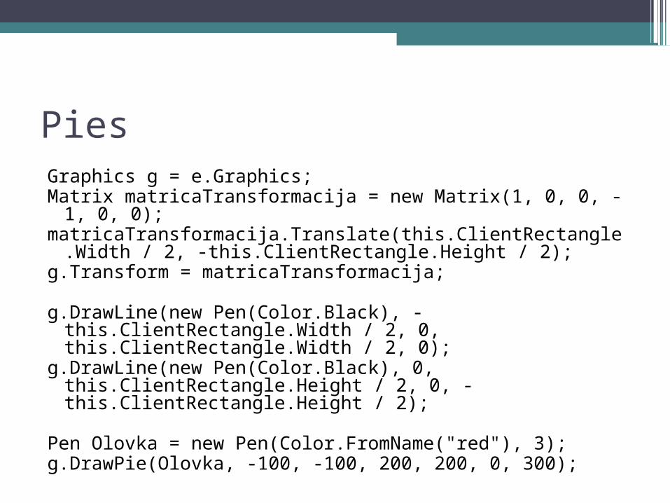
PiesGraphics g = e.Graphics;Matrix matricaTransformacija = new Matrix(1, 0, 0, -1, 0,
0);matricaTransformacija.Translate(this.ClientRectangle.Widt
h / 2, -this.ClientRectangle.Height / 2);g.Transform = matricaTransformacija;
g.DrawLine(new Pen(Color.Black), -this.ClientRectangle.Width / 2, 0, this.ClientRectangle.Width / 2, 0);
g.DrawLine(new Pen(Color.Black), 0, this.ClientRectangle.Height / 2, 0, -this.ClientRectangle.Height / 2);
Pen Olovka = new Pen(Color.FromName("red"), 3);g.DrawPie(Olovka, -100, -100, 200, 200, 0, 300);
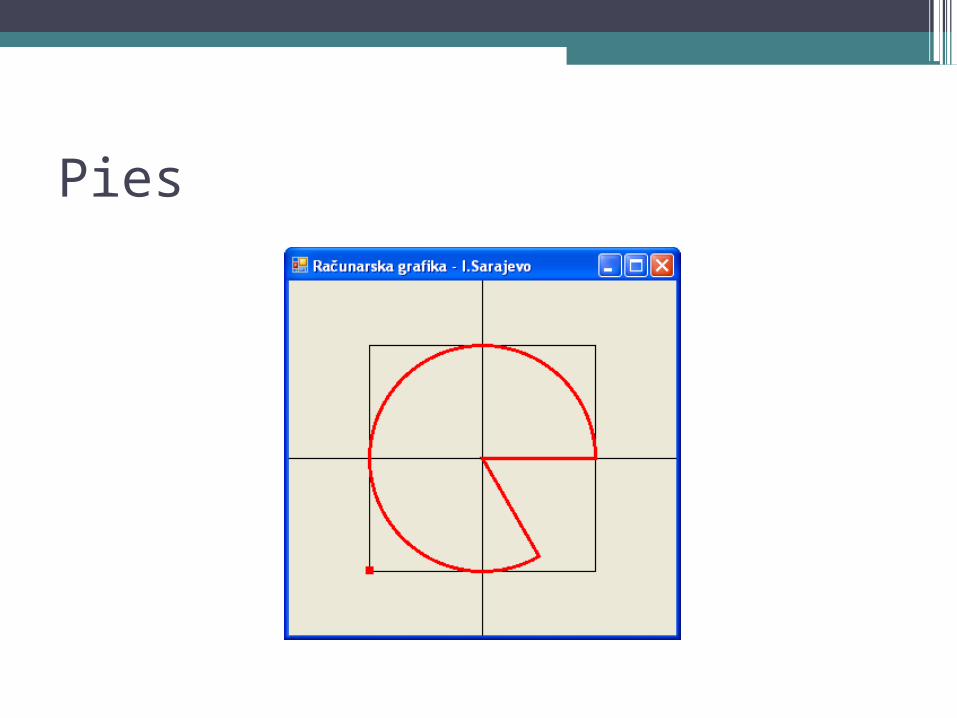
Pies
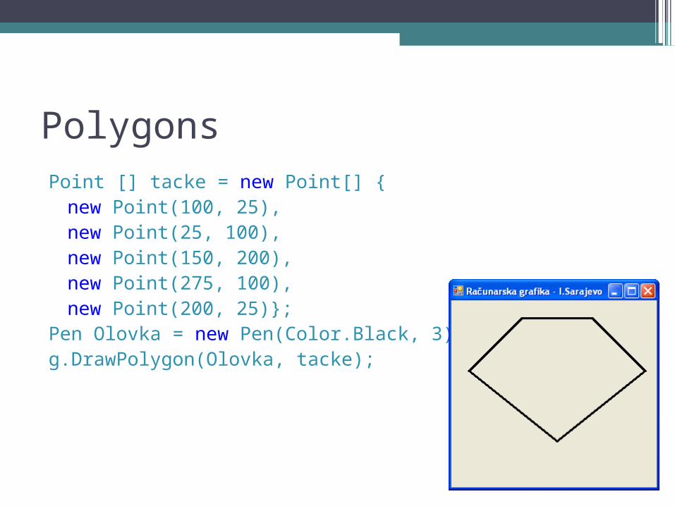
PolygonsPoint [] tacke = new Point[] {new Point(100, 25), new Point(25, 100),new Point(150, 200), new Point(275, 100), new Point(200, 25)};
Pen Olovka = new Pen(Color.Black, 3);g.DrawPolygon(Olovka, tacke);
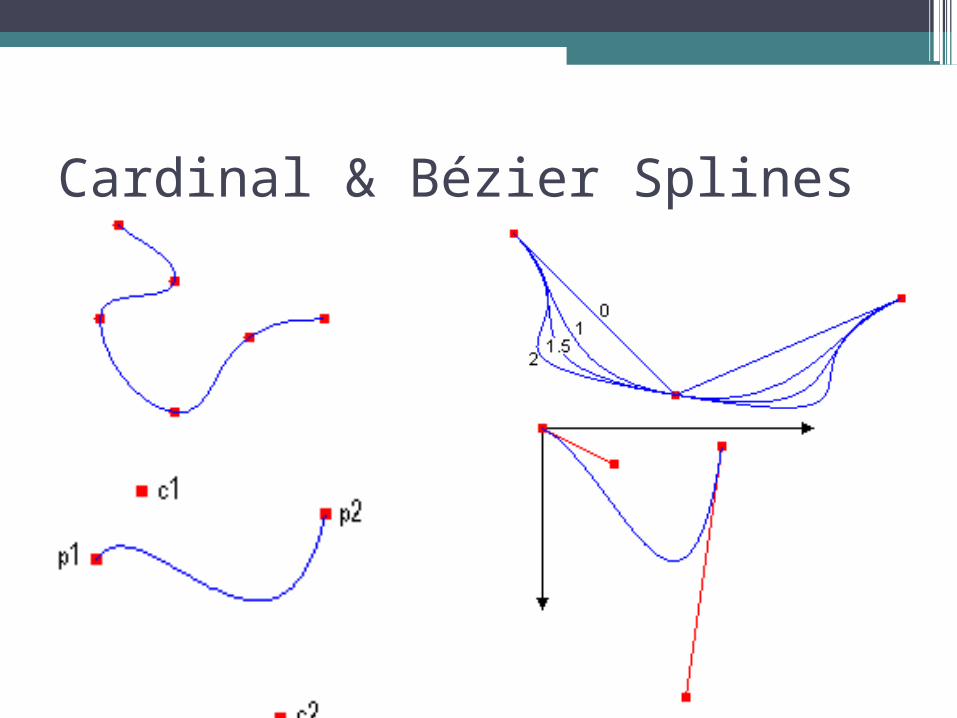
Cardinal & Bézier Splines
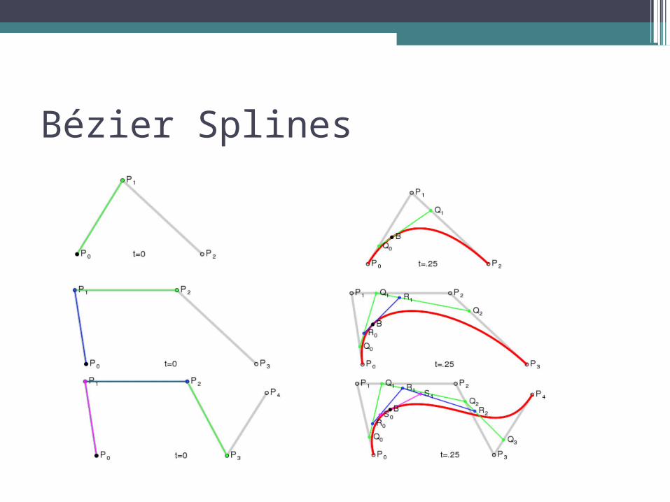
Bézier Splines
Paths
•Paths are formed by combining lines, rectangles, and simple curves.▫Lines▫Rectangles▫Ellipses▫Arcs▫Polygons▫Cardinal splines▫Bézier splines
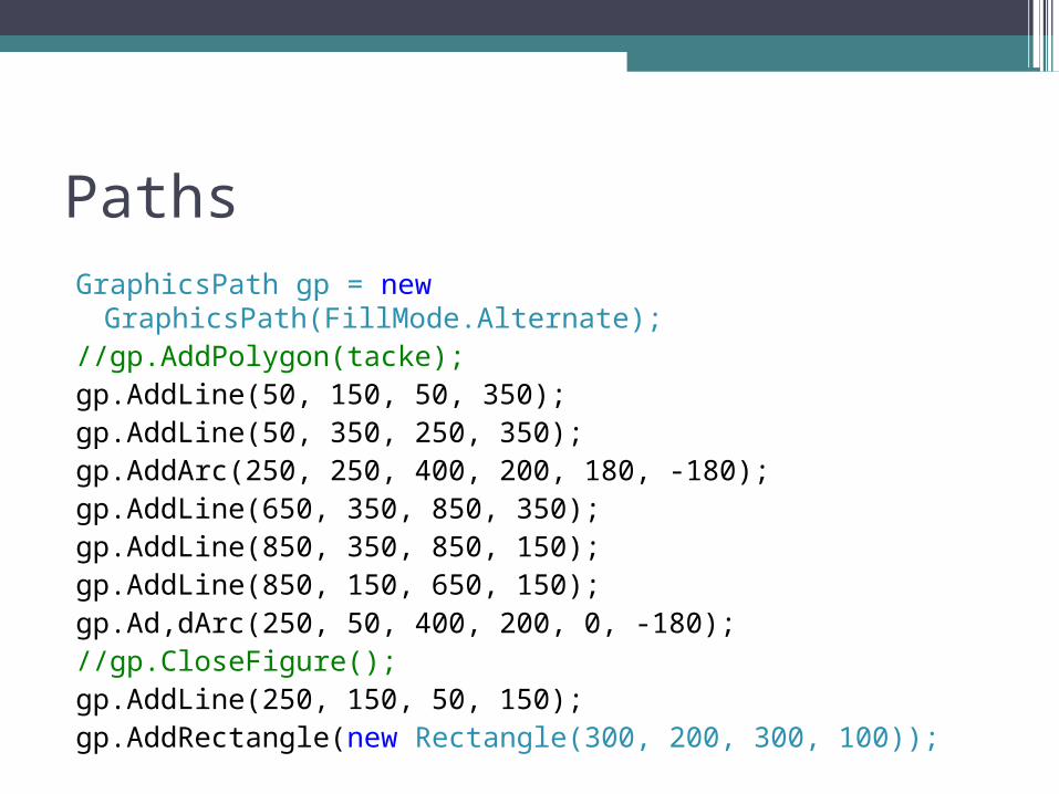
PathsGraphicsPath gp = new GraphicsPath(FillMode.Alternate);
//gp.AddPolygon(tacke);gp.AddLine(50, 150, 50, 350);gp.AddLine(50, 350, 250, 350);gp.AddArc(250, 250, 400, 200, 180, -180);gp.AddLine(650, 350, 850, 350);gp.AddLine(850, 350, 850, 150);gp.AddLine(850, 150, 650, 150);gp.Ad,dArc(250, 50, 400, 200, 0, -180);//gp.CloseFigure();gp.AddLine(250, 150, 50, 150);gp.AddRectangle(new Rectangle(300, 200, 300, 100));
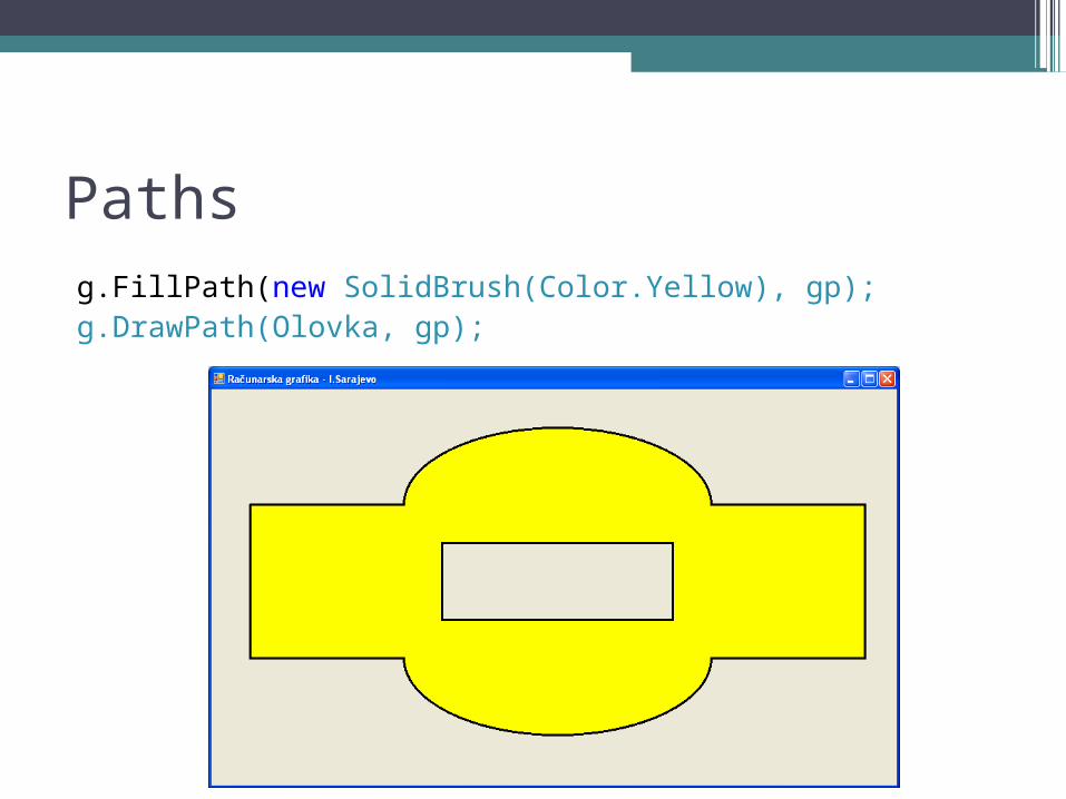
Pathsg.FillPath(new SolidBrush(Color.Yellow), gp);g.DrawPath(Olovka, gp);
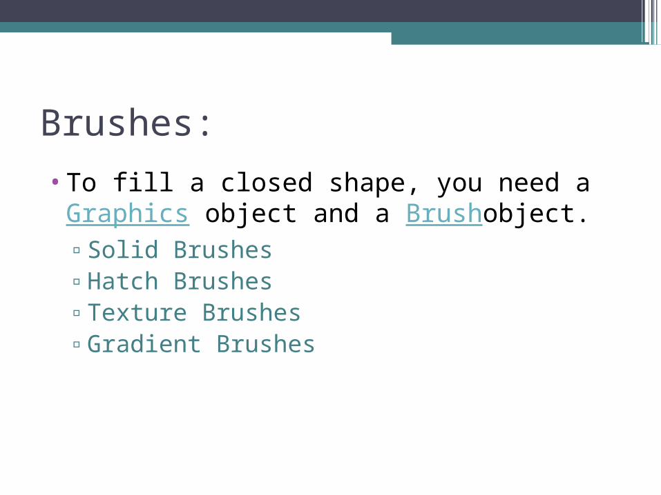
Brushes:
•To fill a closed shape, you need a Graphics object and a Brushobject.▫Solid Brushes▫Hatch Brushes▫Texture Brushes▫Gradient Brushes
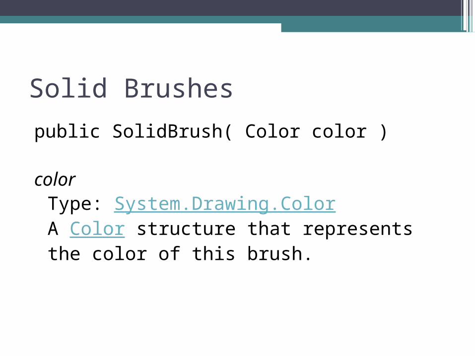
Solid Brushes
public SolidBrush( Color color )
colorType: System.Drawing.ColorA Color structure that represents the color of this brush.
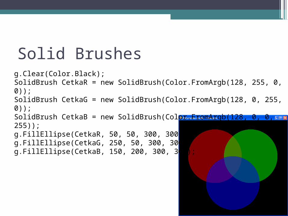
Solid Brushesg.Clear(Color.Black);SolidBrush CetkaR = new SolidBrush(Color.FromArgb(128, 255, 0, 0));SolidBrush CetkaG = new SolidBrush(Color.FromArgb(128, 0, 255, 0));SolidBrush CetkaB = new SolidBrush(Color.FromArgb(128, 0, 0, 255));g.FillEllipse(CetkaR, 50, 50, 300, 300);g.FillEllipse(CetkaG, 250, 50, 300, 300);g.FillEllipse(CetkaB, 150, 200, 300, 300);
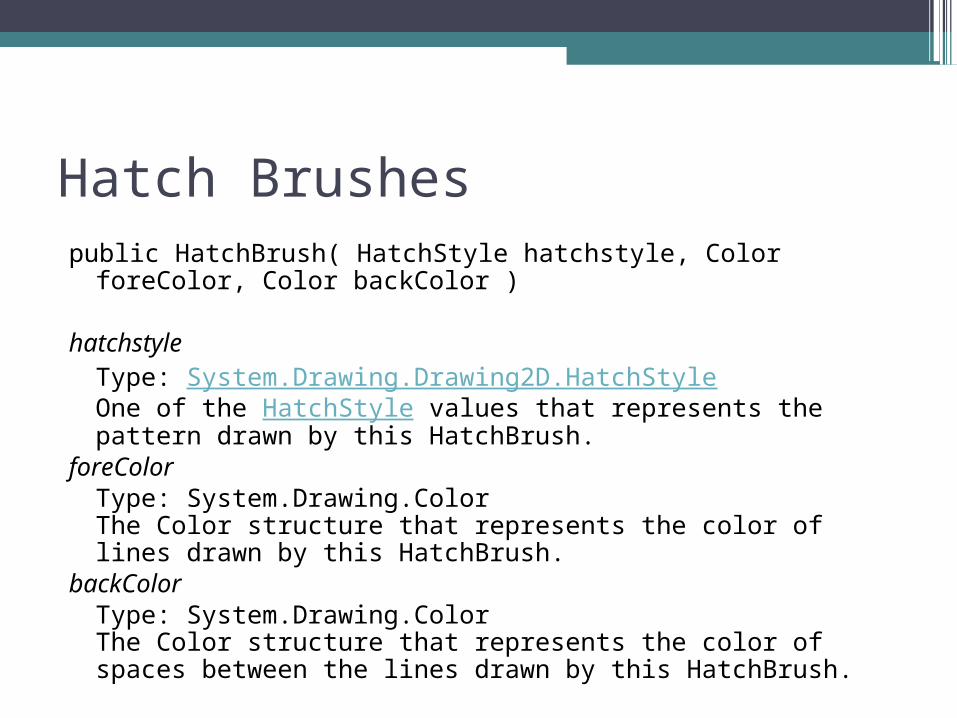
Hatch Brushespublic HatchBrush( HatchStyle hatchstyle, Color foreColor,
Color backColor )
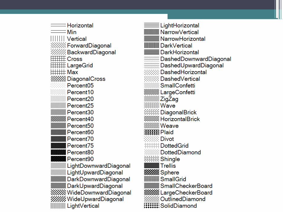
hatchstyleType: System.Drawing.Drawing2D.HatchStyleOne of the HatchStyle values that represents the pattern drawn by this HatchBrush.
foreColorType: System.Drawing.ColorThe Color structure that represents the color of lines drawn by this HatchBrush.
backColorType: System.Drawing.ColorThe Color structure that represents the color of spaces between the lines drawn by this HatchBrush.
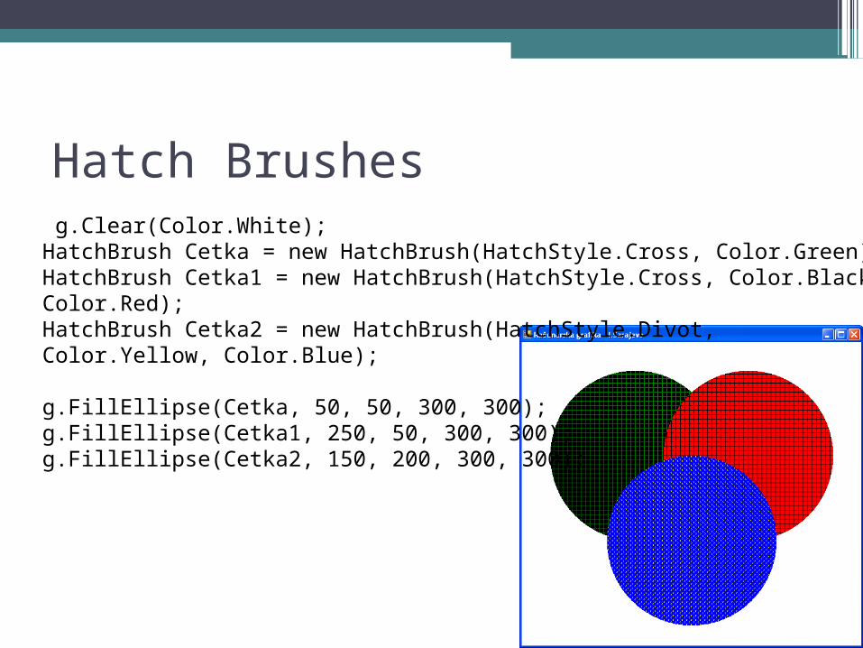
Hatch Brushes g.Clear(Color.White);HatchBrush Cetka = new HatchBrush(HatchStyle.Cross, Color.Green);HatchBrush Cetka1 = new HatchBrush(HatchStyle.Cross, Color.Black, Color.Red);HatchBrush Cetka2 = new HatchBrush(HatchStyle.Divot, Color.Yellow, Color.Blue);
g.FillEllipse(Cetka, 50, 50, 300, 300);g.FillEllipse(Cetka1, 250, 50, 300, 300);g.FillEllipse(Cetka2, 150, 200, 300, 300);
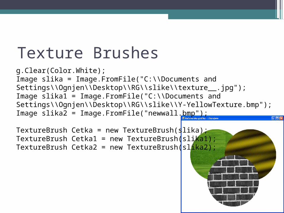
Texture Brushesg.Clear(Color.White);Image slika = Image.FromFile("C:\\Documents and Settings\\Ognjen\\Desktop\\RG\\slike\\texture__.jpg");Image slika1 = Image.FromFile("C:\\Documents and Settings\\Ognjen\\Desktop\\RG\\slike\\Y-YellowTexture.bmp");Image slika2 = Image.FromFile("newwall.bmp"); TextureBrush Cetka = new TextureBrush(slika);TextureBrush Cetka1 = new TextureBrush(slika1);TextureBrush Cetka2 = new TextureBrush(slika2);