Rack Management Unit (RMU) - Fujitsumanuals.ts.fujitsu.com/file/9267/rmu-ug-en.pdf · 1.1 Concept...
256
User guide - English Rack Management Unit (RMU) Hardware, Firmware, Software Interfaces Edition May 2011
Transcript of Rack Management Unit (RMU) - Fujitsumanuals.ts.fujitsu.com/file/9267/rmu-ug-en.pdf · 1.1 Concept...
User guide - English
Rack Management Unit (RMU) Hardware, Firmware, Software Interfaces
Edition May 2011
Comments… Suggestions… Corrections…The User Documentation Department would like toknow your opinion of this manual. Your feedback helpsus optimize our documentation to suit your individual needs.
Feel free to send us your comments by e-mail to email: [email protected].
Certified documentation according to DIN EN ISO 9001:2000To ensure a consistently high quality standard anduser-friendliness, this documentation was created tomeet the regulations of a quality management system which complies with the requirements of the standardDIN EN ISO 9001:2000.
cognitas. Gesellschaft für Technik-Dokumentation mbHwww.cognitas.de
Copyright and Trademarks
© c
ogni
tas.
Ges
ells
chft
für
Tech
nik-
Dok
umen
tatio
n m
bH 2
011
Pfa
d: A
:\Ben
_Nev
is_R
MU
\Han
dbuc
h\en
\rm
u-en
.vor
Copyright © 2011 Fujitsu Technology Solutions GmbH.
All rights reserved.Delivery subject to availability; right of technical modifications reserved.
All hardware and software names used are trademarks of their respective manufacturers.
Rack Management Unit (RMU)
Contents
1 Preface . . . . . . . . . . . . . . . . . . . . . . . . . . . . . . 9
1.1 Concept and target groups for this manual . . . . . . . . . 10
1.2 Documentation . . . . . . . . . . . . . . . . . . . . . . . . . 11
1.3 Notational conventions . . . . . . . . . . . . . . . . . . . . 12
2 Rack Management Unit (RMU) . . . . . . . . . . . . . . . . . 13
2.1 Rack Management Unit (RMU) - Hardware . . . . . . . . . . 142.1.1 Front Panel . . . . . . . . . . . . . . . . . . . . . . . . . . . . 152.1.2 Rear Panel . . . . . . . . . . . . . . . . . . . . . . . . . . . . 18
2.2 Rack Management Unit (RMU) - Firmware . . . . . . . . . . 192.2.1 RMU firmware - Overview . . . . . . . . . . . . . . . . . . . . 202.2.2 Updating the RMU firmware . . . . . . . . . . . . . . . . . . . 22
2.3 Rack Management Unit (RMU) - Technical Data . . . . . . . 23
3 Rack Server Management using the RMU . . . . . . . . . . 25
3.1 Fan speed control . . . . . . . . . . . . . . . . . . . . . . . 26
3.2 Monitoring functions . . . . . . . . . . . . . . . . . . . . . . 29
4 User management for the RMU . . . . . . . . . . . . . . . . 31
4.1 User management concept for the RMU . . . . . . . . . . . 32
4.2 User permissions . . . . . . . . . . . . . . . . . . . . . . . 34
4.3 Local user management . . . . . . . . . . . . . . . . . . . . 364.3.1 Local user management using the RMU web interface . . . . . 364.3.2 SSHv2 public key authentication for local RMU users . . . . . . 384.3.2.1 Creating public and private SSHv2 keys . . . . . . . . . . . 394.3.2.2 Loading the public SSHv2 key onto the RMU from a file . . . 434.3.2.3 Configuring PuTTY and the OpenSSH client for using the
public SSHv2 key . . . . . . . . . . . . . . . . . . . . . . 454.3.2.4 Example: Public SSHv2 key . . . . . . . . . . . . . . . . . 50
Rack Management Unit (RMU)
Contents
© c
ogni
tas.
Ges
ells
chft
für
Tech
nik-
Dok
umen
tatio
n m
bH 2
009
Pfa
d: A
:\Ben
_Nev
is_R
MU
\Han
dbuc
h\en
\rm
u-en
.ivz
4.4 Global user management for the RMU . . . . . . . . . . . . . 514.4.1 Overview . . . . . . . . . . . . . . . . . . . . . . . . . . . . . 524.4.2 RMU user management via an LDAP directory service (concept) 534.4.2.1 Global RMU user management using permission groups
and roles . . . . . . . . . . . . . . . . . . . . . . . . . . . 534.4.2.2 Organizational units (OU) SVS and iRMCgroups . . . . . . . 554.4.2.3 Cross-server, global user permissions . . . . . . . . . . . . 574.4.2.4 iRMCgroups: Permission profiles are defined via permission
groups . . . . . . . . . . . . . . . . . . . . . . . . . . . . . 594.4.2.5 SVS: Permission profiles are defined via roles . . . . . . . . 614.4.3 SVS_LdapDeployer - Generating, maintaining and deleting
the “SVS” and “iRMCgroups” structures . . . . . . . . . . . . . 644.4.3.1 Configuration file (XML file) . . . . . . . . . . . . . . . . . . 644.4.3.2 Starting SVS_LdapDeployer . . . . . . . . . . . . . . . . . 654.4.3.3 -deploy: Create or modify an LDAP structure . . . . . . . . . 674.4.3.4 -delete: Deleting an LDAP structure . . . . . . . . . . . . . 694.4.3.5 -import: Importing an LDAP v1 structure into an LDAP v2
structure . . . . . . . . . . . . . . . . . . . . . . . . . . . . 704.4.3.6 -synchronize: Synchronizing changes made in an LDAP v2
structure with an LDAP v1 structure . . . . . . . . . . . . . . 714.4.4 Typical application scenarios . . . . . . . . . . . . . . . . . . . 734.4.4.1 Performing an initial configuration in which LDAP v1 and
LDAP v2 structures coexist . . . . . . . . . . . . . . . . . . 734.4.4.2 Importing an LDAP v1 structure into an LDAP v2 structure . . 734.4.4.3 Re-generating or expanding an LDAP v2 structure . . . . . . 744.4.4.4 Re-generating an LDAP v2 structure and prompting for
and saving authentication data . . . . . . . . . . . . . . . . 744.4.5 RMU user management via Microsoft Active Directory . . . . . 754.4.5.1 Configuring RMU LDAP/SSL access at the Active Directory
server . . . . . . . . . . . . . . . . . . . . . . . . . . . . . 764.4.5.2 Assigning an RMU user to a role (permission group) . . . . . 814.4.6 RMU user management via Novell eDirectory . . . . . . . . . . 884.4.6.1 Software components and system requirements . . . . . . . 884.4.6.2 Installing Novell eDirectory . . . . . . . . . . . . . . . . . . 894.4.6.3 Configuring Novell eDirectory . . . . . . . . . . . . . . . . . 964.4.6.4 Integrating RMU user management in Novell eDirectory . . 1024.4.6.5 Assigning an RMU user to a permission group . . . . . . . 1084.4.6.6 Tips on administering Novell eDirectory. . . . . . . . . . . 112
Rack Management Unit (RMU)
Contents
4.4.7 RMU user management via OpenLDAP . . . . . . . . . . . . 1154.4.7.1 Installing OpenLDAP . . . . . . . . . . . . . . . . . . . . . 1154.4.7.2 Creating SSL certificates . . . . . . . . . . . . . . . . . . . 1154.4.7.3 Configuring OpenLDAP . . . . . . . . . . . . . . . . . . . 1164.4.7.4 Integrating RMU user management in OpenLDAP. . . . . . 1184.4.7.5 Tips on OpenLDAP administration . . . . . . . . . . . . . . 1224.4.8 Configuring email alerting to global RMU users . . . . . . . . . 1244.4.8.1 Global email alerting . . . . . . . . . . . . . . . . . . . . . 1254.4.8.2 Displaying alert roles . . . . . . . . . . . . . . . . . . . . . 1294.4.8.3 Assigning RMU users to an alert role . . . . . . . . . . . . 1314.4.9 SSL copyright . . . . . . . . . . . . . . . . . . . . . . . . . . 132
5 RMU web interface . . . . . . . . . . . . . . . . . . . . . . . 135
5.1 Logging into the RMU web interface . . . . . . . . . . . . . 136
5.2 Required user permissions . . . . . . . . . . . . . . . . . . 138
5.3 Structure of the user interface . . . . . . . . . . . . . . . . 140
5.4 RMU Information - Information on the RMU and the managed rack server . . . . . . . . . . . . . . . . . . . . . . 143
5.4.1 System Overview - General information on the RMU and the managed rack server . . . . . . . . . . . . . . . . . . . . . . 144
5.4.2 RMU Information - Information on the RMU . . . . . . . . . . . 1495.4.3 Certificate Upload - Load the DSA/RSA certificate and private
DSA/RSA key . . . . . . . . . . . . . . . . . . . . . . . . . . 1525.4.4 Generate a self-signed Certificate - Generate self-signed
RSA certificate . . . . . . . . . . . . . . . . . . . . . . . . . . 1595.4.5 RMU Firmware Update . . . . . . . . . . . . . . . . . . . . . 161
5.5 Sensors - Check status of the sensors . . . . . . . . . . . . 1665.5.1 Fans - Check fans . . . . . . . . . . . . . . . . . . . . . . . . 1675.5.2 Temperature - Check temperature sensors . . . . . . . . . . . 1685.5.3 Voltages - Check voltage sensors . . . . . . . . . . . . . . . . 1695.5.4 Pressure Information - Check pressure sensors . . . . . . . . . 1705.5.5 Contact/Switch Configuration - Configure contact switches . . 1715.5.6 Power Supply - Check power supply . . . . . . . . . . . . . . 1725.5.7 Component Status -
Check status of the RMU components . . . . . . . . . . . . . 173
Rack Management Unit (RMU)
Contents
© c
ogni
tas.
Ges
ells
chft
für
Tech
nik-
Dok
umen
tatio
n m
bH 2
009
Pfa
d: A
:\Ben
_Nev
is_R
MU
\Han
dbuc
h\en
\rm
u-en
.ivz
5.6 System Event Log (SEL) - Displaying and configuring the server’s event log . . . . . . . . . . . . . . . . . . . . . . . 174
5.6.1 System Event Log Content - Show information on the SEL and SEL entries . . . . . . . . . 175
5.6.2 System Event Log Configuration - Configure the SEL . . . . . 178
5.7 Network Settings - Configure the LAN parameters . . . . . 1805.7.1 Network Interface - Configure Ethernet settings on the RMU . 1815.7.2 Ports and Network Services -
Configuring ports and network services . . . . . . . . . . . . 1845.7.3 DHCP Configuration - Configuring the host name for the RMU 1875.7.4 DNS Settings - Enable DNS for the RMU . . . . . . . . . . . . 189
5.8 Alerting - Configure alerting . . . . . . . . . . . . . . . . . 1915.8.1 SNMP Trap Alerting - Configure SNMP trap alerting . . . . . . 1925.8.2 Email Alerting - Configure email alerting . . . . . . . . . . . . 193
5.9 User Management - Manage users . . . . . . . . . . . . . . 1995.9.1 RMU User - local user management on the RMU . . . . . . . 2005.9.2 Directory Service Configuration (LDAP) -
Configuring the directory service at the RMU . . . . . . . . . . 2115.9.2.1 Configuring the RMU for Microsoft Active Directory . . . . . 2145.9.2.2 Configuring RMU for Novell eDirectory / OpenLDAP . . . . 218
5.10 Operating RMU via Telnet/SSH (Remote Manager) . . . . . 224
6 RMU serial port interface (Remote Manager) . . . . . . . . 229
6.1 Operating Remote Manager . . . . . . . . . . . . . . . . . . 230
6.2 Overview of menus . . . . . . . . . . . . . . . . . . . . . . 231
6.3 Logging in . . . . . . . . . . . . . . . . . . . . . . . . . . . 233
6.4 Main menu of the Remote Manager . . . . . . . . . . . . . 234
6.5 Required user permissions . . . . . . . . . . . . . . . . . . 236
6.6 Change the password . . . . . . . . . . . . . . . . . . . . . 236
6.7 System Information - Information on the RMU . . . . . . . . . . . . . . . . . . . . 237
6.8 Enclosure Information - System event log and status of the sensors . . . . . . . . . 238
6.9 RMU processor - IP parameters, identification LEDand RMU reset . . . . . . . . . . . . . . . . . . . . . . . . . 242
Rack Management Unit (RMU)
Contents
6.10 Start a Command Line shell... - Start a SMASH CLP shell . . 244
6.11 Command Line Protocol (CLP) . . . . . . . . . . . . . . . . 245
Index . . . . . . . . . . . . . . . . . . . . . . . . . . . . . . . . . . . . 249

© c
ogni
tas.
Ges
ells
chft
für
Tech
nik-
Dok
umen
tatio
n m
bH 2
009
Pfa
d: A
:\Ben
_Nev
is_R
MU
\Han
dbuc
h\en
\rm
u-en
.ivz
Rack Management Unit (RMU) 9
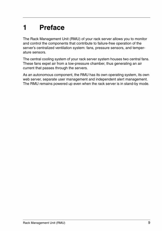
1 PrefaceThe Rack Management Unit (RMU) of your rack server allows you to monitor and control the components that contribute to failure-free operation of the server’s centralized ventilation system: fans, pressure sensors, and temper-ature sensors.
The central cooling system of your rack server system houses two central fans. These fans expel air from a low-pressure chamber, thus generating an air current that passes through the servers.
As an autonomous component, the RMU has its own operating system, its own web server, separate user management and independent alert management. The RMU remains powered up even when the rack server is in stand-by mode.
10 Rack Management Unit (RMU)
Concept and target groups for this manual Preface
© c
ogni
tas.
Ges
ells
chft
für
Tech
nik-
Dok
umen
tatio
n m
bH 2
009
Pfa
d: A
:\Ben
_Nev
is_R
MU
\Han
dbuc
h\en
\rm
u-en
.k01
1.1 Concept and target groups for this manual
This manual will familiarize you with the Rack Management Unit (RMU) that is designed for monitoring and controlling centrally cooled rack server systems.
The manual informs you on the following topics:
● Chapter 2 "Rack Management Unit"
This chapter gives an overview of the RMU’s hardware, firmware, and technical data.
● Chapter 3: "Rack Server Management using the RMU"
This chapter describes how the RMU allows you to monitor and control the components of your rack server system which contribute to failure-free operation of the server’s centralized ventilation system.
● Chapter 4: "User management of the RMU"
This chapter describes in detail the user management of the RMU. The RMU distinguishes two types of user management:
– the RMU internal local user management.
– the global user management of the RMU, which supports the following directory services: Microsoft ActiveDirectory, Novell eDirectory, and Open LDAP.
● Chapter 5: "RMU web interface"
This chapter describes the functionality of the RMU web interface, which among others provides you with access to all system information and data from the sensors such as fan speeds, voltages, etc. The RMU web interface also allows you to configure the RMU settings.
● Chapter 6: "RMU serial port interface (Remote Manager)"
This chapter describes the Telnet-based interface of the RMU, which is known as the Remote Manager. The RMU supports secure connections over SSH (Secure Shell). The Remote Manager interface is identical for Telnet and SSH connections. You can call the Remote Manager over the RMU web interface, or any Telnet/SSH client.
This manual is aimed at system administrators, network administrators, and service staff who have a sound knowledge of hardware and software.
Rack Management Unit (RMU) 11
Preface Documentation
1.2 Documentation
PRIMERGY manuals are available in PDF format on the ServerView Suite DVD 2. The ServerView Suite DVD 2 is supplied with your server. If you no longer have the ServerView Suite DVDs, you can obtain the relevant current versions using the order number U15000-C289 (the order number for the Japanese market: please refer to the configurator of the server http://primeserver.fujitsu.com/primergy/system.html.
The PDF files of the manuals can also be downloaded free of charge from the Internet. The overview page showing the online documentation available on the Internet can be found using the URL (for EMEA market): http://manuals.ts.fujitsu.com.
The PRIMERGY server documentation can be accessed using the Industry standard servers navigation option. For the Japanese market please use the URL: http://primeserver.fujitsu.com/primergy/manual.html.
12 Rack Management Unit (RMU)
Notational conventions
© c
ogni
tas.
Ges
ells
chft
für
Tech
nik-
Dok
umen
tatio
n m
bH 2
009
Pfa
d: A
:\Ben
_Nev
is_R
MU
\Han
dbuc
h\en
\rm
u-en
.k01
1.3 Notational conventions
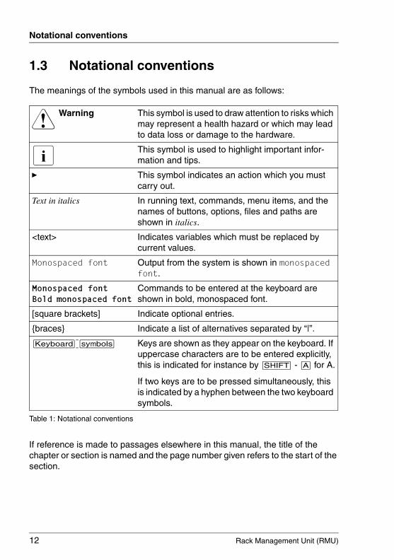
The meanings of the symbols used in this manual are as follows:
If reference is made to passages elsewhere in this manual, the title of the chapter or section is named and the page number given refers to the start of the section.
V Warning This symbol is used to draw attention to risks which may represent a health hazard or which may lead to data loss or damage to the hardware.
I This symbol is used to highlight important infor-mation and tips.
Ê This symbol indicates an action which you must carry out.
Text in italics In running text, commands, menu items, and the names of buttons, options, files and paths are shown in italics.
<text> Indicates variables which must be replaced by current values.
Monospaced font Output from the system is shown in monospaced font.
Monospaced font Bold monospaced font
Commands to be entered at the keyboard are shown in bold, monospaced font.
[square brackets] Indicate optional entries.
{braces} Indicate a list of alternatives separated by “|”.
[Keyboard] [symbols] Keys are shown as they appear on the keyboard. If uppercase characters are to be entered explicitly, this is indicated for instance by [SHIFT] - [A] for A.
If two keys are to be pressed simultaneously, this is indicated by a hyphen between the two keyboard symbols.
Table 1: Notational conventions
Rack Management Unit (RMU) 13
2 Rack Management Unit (RMU)This chapter provides you with information on the following topics:
– Indicators, control features, and connectors of the Rack Management Unit.
– Overview of RMU firmware and how to update RMU firmware.
– Rack server management using the RMU.
14 Rack Management Unit (RMU)
Hardware Rack Management Unit (RMU)
© c
ogni
tas.
Ges
ells
chft
für
Tech
nik-
Dok
umen
tatio
n m
bH 2
009
Pfa
d: A
:\Ben
_Nev
is_R
MU
\Han
dbuc
h\en
\rm
u-en
.k02
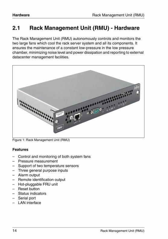
2.1 Rack Management Unit (RMU) - Hardware
The Rack Management Unit (RMU) autonomously controls and monitors the two large fans which cool the rack server system and all its components. It ensures the maintenance of a constant low-pressure in the low pressure chamber, minimizing noise level and power dissipation and reporting to external datacenter management facilities.
Figure 1: Rack Management Unit (RMU)
Features
– Control and monitoring of both system fans– Pressure measurement– Support of two temperature sensors– Three general purpose inputs– Alarm output– Remote identification output– Hot-pluggable FRU unit– Reset button – Status indicators– Serial port– LAN interface

Rack Management Unit (RMU) 15
Rack Management Unit (RMU) Hardware
2.1.1 Front Panel
Ambient pressure sensor and connectors
Figure 2: RMU front panel - connectors
1 Pressure sensor(Measuring point for ambient pressure)
2 10/100 Mbit LAN connector
3 COM1 serial connector for Telnet/SSH based Remote Manager interface
16 Rack Management Unit (RMU)
Hardware Rack Management Unit (RMU)
© c
ogni
tas.
Ges
ells
chft
für
Tech
nik-
Dok
umen
tatio
n m
bH 2
009
Pfa
d: A
:\Ben
_Nev
is_R
MU
\Han
dbuc
h\en
\rm
u-en
.k02
Front indicators and controls
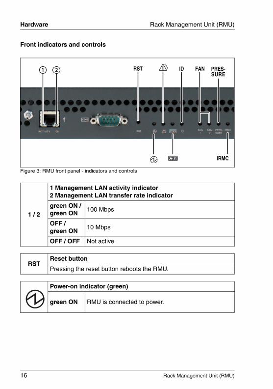
Figure 3: RMU front panel - indicators and controls
1 / 2
1 Management LAN activity indicator2 Management LAN transfer rate indicator
green ON / green ON
100 Mbps
OFF / green ON
10 Mbps
OFF / OFF Not active
RSTReset button
Pressing the reset button reboots the RMU.
Power-on indicator (green)
green ON RMU is connected to power.

Rack Management Unit (RMU) 17
Rack Management Unit (RMU) Hardware
Global Error indicator (orange)
orange ONA prefailure event has been detected that requires (precautionary) service intervention.
orange FLASHING
An error was detected that requires service intervention.
I If the event is still acute after a power failure, the indicator is activated after the restart.
You can find more details on the indicated errors in the System Event Log (SEL).
Customer Self Service indicator (currently of no importance)
There are no CSS components available.
IDID indicator (blue)
blue ONLights up blue when the system has been selected for identification in the RMU web interface
FAN 1FAN 2
Fan failure indicators (yellow)
yellow ONFan 1 / 2 prefailure or failure.Fan 1 / 2 has to be replaced immediately.
PRES-SURE
Air pressure indicators (orange)
orange ON
Prefailure or error
Pressure level is out of range. Under-pressure cannot be achieved although fans run at full speed.
I The PRESSURE indicators only light up in combination with the Global Error indicator.
iRMC
iRMC indicator (green)
green FLASHING
iRMC S2 alive: RMU internal server management controller (iRMC S2) is working correctly.
green ON or OFF
iRMC S2 dead.
18 Rack Management Unit (RMU)
Hardware Rack Management Unit (RMU)
© c
ogni
tas.
Ges
ells
chft
für
Tech
nik-
Dok
umen
tatio
n m
bH 2
009
Pfa
d: A
:\Ben
_Nev
is_R
MU
\Han
dbuc
h\en
\rm
u-en
.k02
2.1.2 Rear Panel
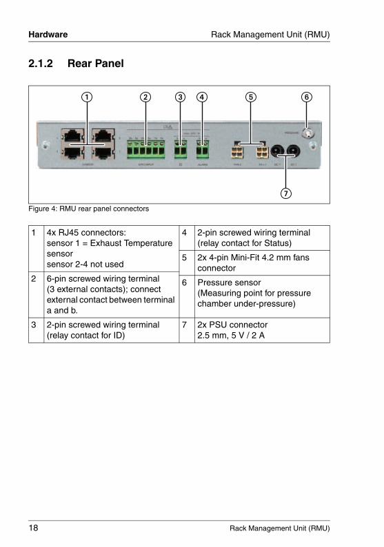
Figure 4: RMU rear panel connectors
1 4x RJ45 connectors:sensor 1 = Exhaust Temperature sensorsensor 2-4 not used
4 2-pin screwed wiring terminal(relay contact for Status)
5 2x 4-pin Mini-Fit 4.2 mm fans connector
2 6-pin screwed wiring terminal (3 external contacts); connect external contact between terminal a and b.
6 Pressure sensor(Measuring point for pressure chamber under-pressure)
3 2-pin screwed wiring terminal(relay contact for ID)
7 2x PSU connector2.5 mm, 5 V / 2 A
Rack Management Unit (RMU) 19
Rack Management Unit (RMU) Firmware
2.2 Rack Management Unit (RMU) - Firmware
The RMU uses two different firmware images in order to provide a fallback mechanism in the event of a firmware failure.
The two firmware images are stored on a 16-MB EEPROM (Electrically Erasable Programmable Read-Only Memory):
– Firmware image 1 (low FW image)– Firmware image 2 (high FW image)
The firmware of the RMU is not executed in the EEPROM, but is instead loaded into SRAM memory on startup and executed there. This means that it is possible to update both active and inactive firmware images online, i.e. with the server operating system (Windows or Linux) running.
I Information on the currently running RMU firmware and on EEPROM can be found in the RMU web interface, page RMU Firmware Update (see page 161).

20 Rack Management Unit (RMU)
Firmware Rack Management Unit (RMU)
© c
ogni
tas.
Ges
ells
chft
für
Tech
nik-
Dok
umen
tatio
n m
bH 2
009
Pfa
d: A
:\Ben
_Nev
is_R
MU
\Han
dbuc
h\en
\rm
u-en
.k02
2.2.1 RMU firmware - Overview
Active and passive firmware image
One of the two firmware images is active (running) at any given time, while the other is inactive. The firmware image that is active depends on the so-called firmware selector (see page 21).
Structure of the RMU EEPROM
The EEPROM of the RMU contains one area for firmware image 1 and one area for firmware image 2:
Figure 5: Structure of the RMU EEPROM
Runtime firmware
SDRR (and configuration table)
not used
Runtime firmware
SDRR (and configuration table)
Bootloader
8 MB forfirmware image 2
8 MB forfirmware image 1
Rack Management Unit (RMU) 21
Rack Management Unit (RMU) Firmware
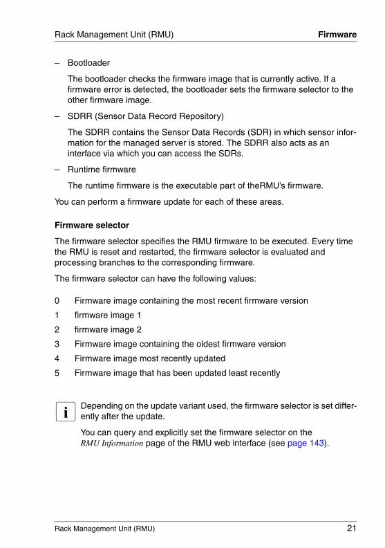
– Bootloader
The bootloader checks the firmware image that is currently active. If a firmware error is detected, the bootloader sets the firmware selector to the other firmware image.
– SDRR (Sensor Data Record Repository)
The SDRR contains the Sensor Data Records (SDR) in which sensor infor-mation for the managed server is stored. The SDRR also acts as an interface via which you can access the SDRs.
– Runtime firmware
The runtime firmware is the executable part of theRMU’s firmware.
You can perform a firmware update for each of these areas.
Firmware selector
The firmware selector specifies the RMU firmware to be executed. Every time the RMU is reset and restarted, the firmware selector is evaluated and processing branches to the corresponding firmware.
The firmware selector can have the following values:
I Depending on the update variant used, the firmware selector is set differ-ently after the update.
You can query and explicitly set the firmware selector on the RMU Information page of the RMU web interface (see page 143).
0 Firmware image containing the most recent firmware version
1 firmware image 1
2 firmware image 2
3 Firmware image containing the oldest firmware version
4 Firmware image most recently updated
5 Firmware image that has been updated least recently
22 Rack Management Unit (RMU)
Firmware Rack Management Unit (RMU)
© c
ogni
tas.
Ges
ells
chft
für
Tech
nik-
Dok
umen
tatio
n m
bH 2
009
Pfa
d: A
:\Ben
_Nev
is_R
MU
\Han
dbuc
h\en
\rm
u-en
.k02
2.2.2 Updating the RMU firmware
You can update the RMU firmware via the RMU Update page in the RMU Web Interface (see section "RMU Firmware Update" on page 161).
I The current firmware versions can be downloaded manually from the Download section of the Fujitsu Technology Solutions web server.
I Before updating the firmware, read the supplementary documentation supplied with the new firmware carefully (in particular the Readme files).
I The RMU must be rebooted to activate the updated firmware.
V CAUTION!
When updating the firmware, note that problem-free operation of the firmware can only be guaranteed if the runtime firmware and the SDR (Sensor Data Record, see page 20) both belong to the same firmware release.
Rack Management Unit (RMU) 23
Rack Management Unit (RMU) Technical data
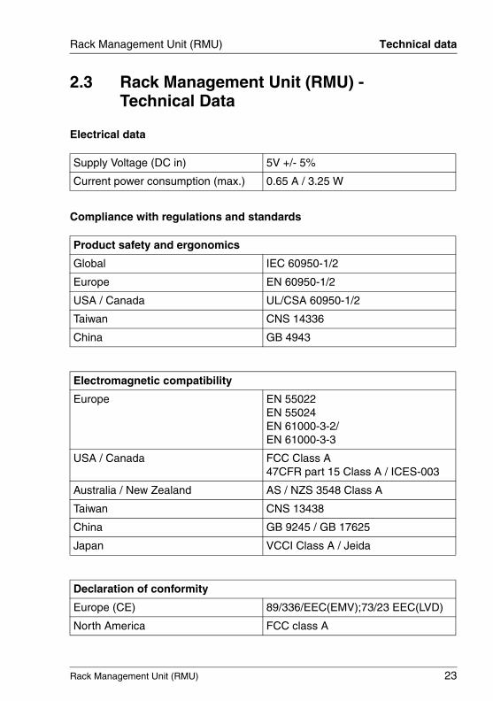
2.3 Rack Management Unit (RMU) - Technical Data
Electrical data
Compliance with regulations and standards
Supply Voltage (DC in) 5V +/- 5%
Current power consumption (max.) 0.65 A / 3.25 W
Product safety and ergonomics
Global IEC 60950-1/2
Europe EN 60950-1/2
USA / Canada UL/CSA 60950-1/2
Taiwan CNS 14336
China GB 4943
Electromagnetic compatibility
Europe EN 55022EN 55024EN 61000-3-2/EN 61000-3-3
USA / Canada FCC Class A47CFR part 15 Class A / ICES-003
Australia / New Zealand AS / NZS 3548 Class A
Taiwan CNS 13438
China GB 9245 / GB 17625
Japan VCCI Class A / Jeida
Declaration of conformity
Europe (CE) 89/336/EEC(EMV);73/23 EEC(LVD)
North America FCC class A

24 Rack Management Unit (RMU)
Technical data Rack Management Unit (RMU)
© c
ogni
tas.
Ges
ells
chft
für
Tech
nik-
Dok
umen
tatio
n m
bH 2
009
Pfa
d: A
:\Ben
_Nev
is_R
MU
\Han
dbuc
h\en
\rm
u-en
.k02
Mechanical values and weight
Mounting
The RMU must be mounted into a chassis slot.
V IMPORTANT!
The unobstructed suctioning of ambient air from the front cover (due to the centralized ventilation) must be ensured.
Ambient conditions
V CAUTION!
Condensation during operation must be avoided!
Approvals
Global CB
USA / Canada CSAUS / CSAC
Width 255 mm
Depth 171 mm
Height 45 mm / 1 HU
Weight 1.18 kg
Environment class 3K2Environment class 2K2
DIN IEC 721 section 3-3DIN IEC 721 section 3-2
Temperature:
Operating (3K2)
Transport (2K2)
10oC ... 35oC
-25oC ... 60oC
Humidity 10% .. 85% RH non-condensingCondensation during operation must be avoided.
Rack Management Unit (RMU) 25
3 Rack Server Management using the RMU
The Rack Management Unit (RMU) allows you to monitor and control the components of the rack server system that contribute to failure-free operation of the server’s centralized ventilation system.
The RMU provides two interfaces for monitoring and configuring the centralized ventilation system:
– the RMU web interface (see page 135)
– the RMU serial port interface (see page 229).
The RMU automatically and autonomously controls the speed of the central ventilation fans (Fan 1 and Fan 2) and provides a wide range of monitoring functions.
This chapter provides you with information on the following topics:
– Autonomous fan speed control by the RMU and the settings that can be made to influence it.
– Monitoring functions provided by the RMU.
26 Rack Management Unit (RMU)
Fan speed control Rack management using the RMU
© c
ogni
tas.
Ges
ells
chft
für
Tech
nik-
Dok
umen
tatio
n m
bH 2
009
Pfa
d: A
:\Ben
_Nev
is_R
MU
\Han
dbuc
h\en
\rm
u-en
.k03
3.1 Fan speed control
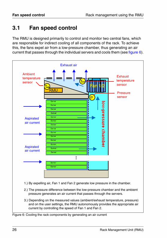
The RMU is designed primarily to control and monitor two central fans, which are responsible for indirect cooling of all components of the rack. To achieve this, the fans expel air from a low-pressure chamber, thus generating an air current that passes through the individual servers and cools them (see figure 6).
Figure 6: Cooling the rack components by generating an air current
Fan 1/2sensor
Exhausttemperaturesensor
sensor
1.) By expelling air, Fan 1 and Fan 2 generate low pressure in the chamber.
2.) The pressure difference between the low-pressure chamber and the ambient
3.) Depending on the measured values (ambient/exhaust temperature, pressure)
pressure generates an air current that passes through the servers.
and on the user settings, the RMU autonomously provides the appropriate aircurrent by controlling the speed of Fan 1 and Fan 2.
Aspiratedair current
Aspiratedair current
Exhaust air
Fan 1/2
Ambienttemperature
Pressure
Rack Management Unit (RMU) 27
Rack management using the RMU Fan speed control
The RMU autonomously controls Fan 1 and Fan 2 with the following objectives:
– Minimal power consumption and noise level.
– Permanent fan monitoring allows you to detect a fan malfunction without delay.
– Redundant fans (Fan 1 and Fan 2) provide failover protection: If one fan fails, the RMU will automatically speed up the other fan, thus guaranteeing that the appropriate air current is maintained.
RMU autonomously controls the fan speed
The RMU automatically controls the fan speed by considering the following aspects:
– The cooling capacity of the fans at maximum speed is designed for an ambient temperature of 35o C. At a lower ambient temperature, a low fan speed is adequate.
– At low working loads, the RMU minimizes power consumption by reducing the fan speed as much as possible.
– Fan 1 and Fan 2 are located within the exhaust air current and must not exceed their operating temperature. The RMU therefore increases the fan speed when the exhaust air temperature reaches the warning value.
Pressure profiles
To optimize central ventilation of your rack server system, the RMU allows you to choose between the pressure profiles Low, Medium, High:
LowOptimizes power saving at low workload.Low fan speed results in a low power consumption of the fans and does not have much impact on the power consumption of the individual servers at a low workload. The performance at high workload may be reduced.
MediumDefault setting.
28 Rack Management Unit (RMU)
Fan speed control Rack management using the RMU
© c
ogni
tas.
Ges
ells
chft
für
Tech
nik-
Dok
umen
tatio
n m
bH 2
009
Pfa
d: A
:\Ben
_Nev
is_R
MU
\Han
dbuc
h\en
\rm
u-en
.k03
HighOptimizes power consumption at high workload. An increased cooling rate reduces the temperature, thus resulting in less power consumption of the individual servers (due to the thermal behavior of semiconductors).
You can specify the appropriate pressure profile using the RMU web interface (see the section "Pressure Information - Check pressure sensors" on page 170).
Rack Management Unit (RMU) 29
Rack management using the RMU Monitoring functions
3.2 Monitoring functions
The RMU permanently informs you of the status of the following components and sensors at the RMU web interface (see the section "Sensors - Check status of the sensors" on page 166:
– fan speed– fan prefailure detection– voltage – pressure – pressure leakage status – temperature – general purpose input output (GPIO)
Fan speed monitoring
The RMU monitors the fan speed of Fan 1 and Fan 2. If one of the fans slows down to a lower critical value, the RMU generates an alert.
I Lower critical limit is 840rpm.
Fan prefailure detection
In the course of the production process, each fan’s maximum speed is regis-tered. When replacing a fan, you need to register the fan speed again. The registered value is assumed to be 100%. If daily full speed measurements exceed 70% of the registered value, the RMU generates an alert.
Voltage monitoring
The RMU provides information on the status of voltage sensors assigned to the rack server components. Each time the voltage exceeds a critical level, the RMU generates a corresponding system event log (SEL) entry and an alert.
Pressure monitoring
The RMU monitors the pressure in the low-pressure chamber. Whenever the pressure exceeds the defined limits, the RMU generates a system event log (SEL) entry and switches on the pressure LED.
30 Rack Management Unit (RMU)
Monitoring functions Rack management using the RMU
© c
ogni
tas.
Ges
ells
chft
für
Tech
nik-
Dok
umen
tatio
n m
bH 2
009
Pfa
d: A
:\Ben
_Nev
is_R
MU
\Han
dbuc
h\en
\rm
u-en
.k03
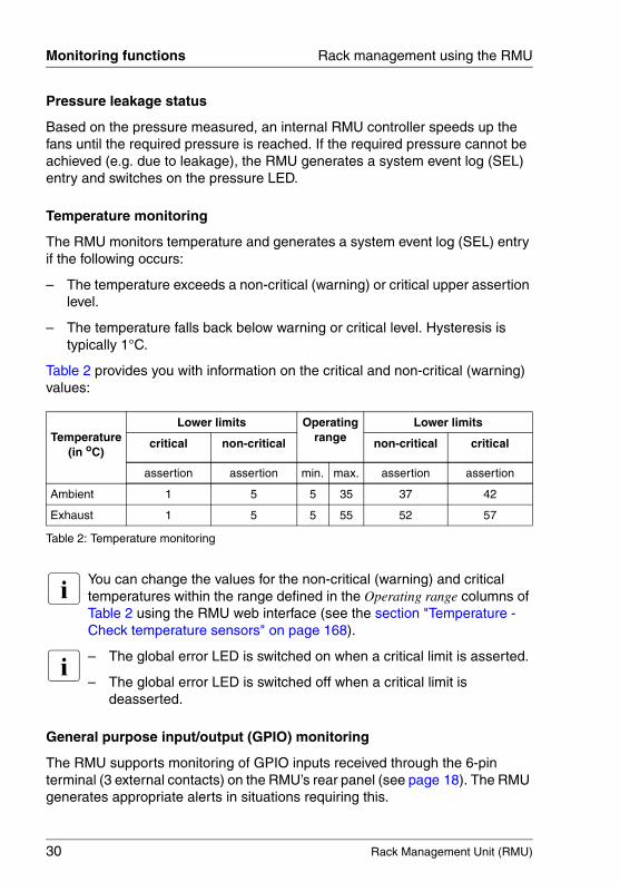
Pressure leakage status
Based on the pressure measured, an internal RMU controller speeds up the fans until the required pressure is reached. If the required pressure cannot be achieved (e.g. due to leakage), the RMU generates a system event log (SEL) entry and switches on the pressure LED.
Temperature monitoring
The RMU monitors temperature and generates a system event log (SEL) entry if the following occurs:
– The temperature exceeds a non-critical (warning) or critical upper assertion level.
– The temperature falls back below warning or critical level. Hysteresis is typically 1°C.
Table 2 provides you with information on the critical and non-critical (warning) values:
I You can change the values for the non-critical (warning) and critical temperatures within the range defined in the Operating range columns of Table 2 using the RMU web interface (see the section "Temperature - Check temperature sensors" on page 168).
I – The global error LED is switched on when a critical limit is asserted.
– The global error LED is switched off when a critical limit is deasserted.
General purpose input/output (GPIO) monitoring
The RMU supports monitoring of GPIO inputs received through the 6-pin terminal (3 external contacts) on the RMU’s rear panel (see page 18). The RMU generates appropriate alerts in situations requiring this.
Temperature(in oC)
Lower limits Operatingrange
Lower limits
critical non-critical non-critical critical
assertion assertion min. max. assertion assertion
Ambient 1 5 5 35 37 42
Exhaust 1 5 5 55 52 57
Table 2: Temperature monitoring
Rack Management Unit (RMU) 31
4 User management for the RMUUser management for the RMU uses two different types of user identifications:
– Local user identifications are stored locally in the RMU’s non-volatile storage and are managed via the RMU user interfaces.
– Global user identifications are stored in the central data store of a directory service and are managed via this directory service’s interfaces.
The following directory services are currently supported for global RMU user management:
– Microsoft® Active Directory – Novell® eDirectory – OpenLDAP
This chapter provides information on the following topics:
– User management concept for the RMU– User permissions– Local user management on the RMU– Global user management using the individual directory services
32 Rack Management Unit (RMU)
Concept User management on the RMU
© c
ogni
tas.
Ges
ells
chft
für
Tech
nik-
Dok
umen
tatio
n m
bH 2
009
Pfa
d: A
:\Ben
_Nev
is_R
MU
\Han
dbuc
h\en
\rm
u-en
.k04
4.1 User management concept for the RMU
User management for the RMU permits the parallel administration of local and global user identifications.
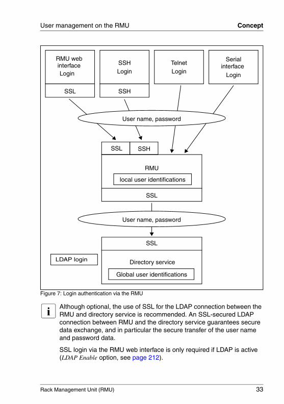
When validating the authentication data (user name, password) which users enter when logging in to one of the RMU interfaces, RMU proceeds as follows (see also figure 7 on page 33):
1. The RMU compares the user name and password with the locally stored user identifications:
● If the user is authenticated successfully by RMU (user name and password are valid) then the user can log in.
● Otherwise, the RMU continues the verification with step 2.
2. The RMU authenticates itself at the directory service via LDAP with a user name and password, determines the user rights by means of an LDAP query and checks whether the user is authorized to work with these at the RMU.
Rack Management Unit (RMU) 33
User management on the RMU Concept
Figure 7: Login authentication via the RMU
I Although optional, the use of SSL for the LDAP connection between the RMU and directory service is recommended. An SSL-secured LDAP connection between RMU and the directory service guarantees secure data exchange, and in particular the secure transfer of the user name and password data.
SSL login via the RMU web interface is only required if LDAP is active (LDAP Enable option, see page 212).
RMU webinterfaceLogin
TelnetLogin
Login
Serialinterface SSH
Login
SSHSSL
RMU
SSL
SSL SSH
Directory service
SSL
User name, password
local user identifications
Global user identifications
User name, password
LDAP login
34 Rack Management Unit (RMU)
User permissions User management on the RMU
© c
ogni
tas.
Ges
ells
chft
für
Tech
nik-
Dok
umen
tatio
n m
bH 2
009
Pfa
d: A
:\Ben
_Nev
is_R
MU
\Han
dbuc
h\en
\rm
u-en
.k04
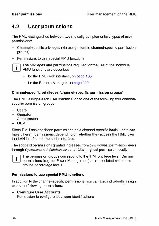
4.2 User permissions
The RMU distinguishes between two mutually complementary types of user permissions:
– Channel-specific privileges (via assignment to channel-specific permission groups)
– Permissions to use special RMU functions
I The privileges and permissions required for the use of the individual RMU functions are described
– for the RMU-web interface, on page 135,
– for the Remote Manager, on page 229.
Channel-specific privileges (channel-specific permission groups)
The RMU assigns each user identification to one of the following four channel-specific permission groups:
– Users– Operator– Administrator– OEM
Since RMU assigns these permissions on a channel-specific basis, users can have different permissions, depending on whether they access the RMU over the LAN interface or the serial interface.
The scope of permissions granted increases from User (lowest permission level) through Operator and Administrator up to OEM (highest permission level).
I The permission groups correspond to the IPMI privilege level. Certain permissions (e.g. for Power Management) are associated with these groups or privilege levels.
Permissions to use special RMU functions
In addition to the channel-specific permissions, you can also individually assign users the following permissions:
– Configure User AccountsPermission to configure local user identifications

Rack Management Unit (RMU) 35
User management on the RMU User permissions
– Configure RMU SettingsPermission to configure the RMU settings.
Preconfigured user ID
The firmware of the RMU provides a default administrator ID for the RMU which possesses all permissions:
I Both the administrator ID and the password are case-sensitive in the case of local users.
It is urgently recommended that you create a new administrator account as soon as possible once you have logged in, and then delete the default administrator account or at least change the password for the account (see section "RMU User - local user management on the RMU" on page 200).
Administrator ID: admin
Password: admin
36 Rack Management Unit (RMU)
... locally via the web interface User management on the RMU
© c
ogni
tas.
Ges
ells
chft
für
Tech
nik-
Dok
umen
tatio
n m
bH 2
009
Pfa
d: A
:\Ben
_Nev
is_R
MU
\Han
dbuc
h\en
\rm
u-en
.k04
4.3 Local user management
The RMU possesses its own local user management. Up to 16 users to be configured with passwords and be assigned various rights depending on the user groups they belong to. The user identifications are stored in the RMU’s local, non-volatile storage. You can perform local user management using the RMU web interface.
4.3.1 Local user management using the RMU web interface
I User management on the RMU requires Configure User Accounts permission.
You can view a list of configured users under the web interface. You can also configure new users, change the configuration of existing users and remove users from the list.
Ê Start the RMU web interface (see section "Logging into the RMU web interface" on page 136).
Showing the list of configured users
Ê In the navigation area, click the User Management - RMU User function.
The User Management page opens containing a list of configured users (see page 199). Here, you can delete users and call the page for configuring new users.
Configuring new users
Ê On the User Management page, click the New User button.
The New User Configuration page opens. This page allows you to configure the basic settings for the new user. This page is described in "New User Configuration - Configuring a new user" on page 201.
Rack Management Unit (RMU) 37
User management on the RMU ... locally via the web interface
Modifying the configuration of a user
Ê On the User Management page, click the name of the user whose configu-ration parameters you want to change.
The User “<name>” Configuration page opens showing the settings for the selected user. Here, you can change the configuration parameters for the new user. This page is described in "User “<name>” Configuration - User configuration (details)" on page 202.
Deleting users
Ê On the User Management page, click on the Delete button in the same line as the user to be deleted.
38 Rack Management Unit (RMU)
SSHv2 public key support User management on the RMU
© c
ogni
tas.
Ges
ells
chft
für
Tech
nik-
Dok
umen
tatio
n m
bH 2
009
Pfa
d: A
:\Ben
_Nev
is_R
MU
\Han
dbuc
h\en
\rm
u-en
.k04
4.3.2 SSHv2 public key authentication for local RMU users
In addition to authentication by means of a user name and password, the RMU also supports SSHv2-based public key authentication using pairs of public and private keys for local users. To implement SSHv2 public key authentication, the SSHv2 key of an RMU user is uploaded to the RMU and the RMU user uses its private key with the program PuTTY or the OpenSSH client program ssh, for example.
The RMU supports the following types of public keys:
– SSH DSS (minimum requirement)– SSH RSA (recommended)
The public SSHv2 keys that you upload to the RMU can be available either in RFC4716 format or in OpenSSH format (see page 50).
Public key authentication
In outline, public key authentication of a user on the RMU happens as follows:
The user who wishes to log into the RMU creates the key pair:
– The private key is read-protected and remains on the user's computer.
– The user (or administrator) uploads the public key to the RMU.
If the configuration allows this, the user can now log into the RMU extremely securely and without the need to enter a password. The user is only responsible for keeping its private key secret.
The following steps are necessary to set up private key authentication. They are described in the subsequent sections:
1. Creating the public and private SSHv2 keys with the program PuTTYgen or ssh-keygen and saving them in separate files (see page 39).
2. Loading the public SSHv2 key onto the RMU from a file (see page 43).
3. Configuring the program PuTTY or ssh for SSHv2 access to the RMU (see page 45).
Rack Management Unit (RMU) 39
User management on the RMU SSHv2 public key support
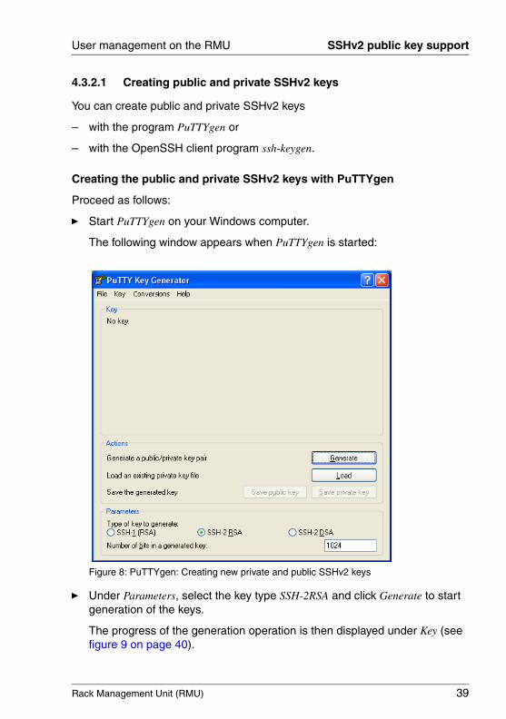
4.3.2.1 Creating public and private SSHv2 keys
You can create public and private SSHv2 keys
– with the program PuTTYgen or
– with the OpenSSH client program ssh-keygen.
Creating the public and private SSHv2 keys with PuTTYgen
Proceed as follows:
Ê Start PuTTYgen on your Windows computer.
The following window appears when PuTTYgen is started:
Figure 8: PuTTYgen: Creating new private and public SSHv2 keys
Ê Under Parameters, select the key type SSH-2RSA and click Generate to start generation of the keys.
The progress of the generation operation is then displayed under Key (see figure 9 on page 40).

40 Rack Management Unit (RMU)
SSHv2 public key support User management on the RMU
© c
ogni
tas.
Ges
ells
chft
für
Tech
nik-
Dok
umen
tatio
n m
bH 2
009
Pfa
d: A
:\Ben
_Nev
is_R
MU
\Han
dbuc
h\en
\rm
u-en
.k04
Figure 9: PuTTYgen: Creating a new key pair (progress bar).
Ê Move the mouse pointer over the blank area of the progress display to increase the randomness of the generated keys.
When the keys have been generated, PuTTYgen displays the key and the fingerprint of the public SSHv2 key:
Figure 10: PuTTYgen: Creating a new private SSHv2 key (progress bar).
Ê Click Save public key to save the public SSHv2 key to a file. You can upload the public key to the RMU from this file (see page 43).
Ê Click Save private key to save the private SSHv2 key to a file for use with PuTTY (see page 45).

Rack Management Unit (RMU) 41
User management on the RMU SSHv2 public key support
Creating the public and private SSHv2 keys with ssh-keygen
I If it is not already pre-installed in the Linux distribution you are using, you can obtain OpenSSH from http://www.openssh.org.
You will find a detailed description of the operands in the OpenSSH OpenSSH manual pages under http://www.openssh.org/manual.html.
Proceed as follows:
Ê Call ssh-keygen to generate an RSA key pair:
ssh-keygen -t rsa
ssh-keygen logs the progress of the key generation operation. ssh-keygen queries the user for the file name under which the private key is to be stored and for the passphrase for the private key. ssh-keygen stores the resulting private and public SSHv2 keys in separate files and displays the fingerprint of the public key.
Example: Generating an RSA key pair with ssh -keygen
1
2
3
4
5
42 Rack Management Unit (RMU)
SSHv2 public key support User management on the RMU
© c
ogni
tas.
Ges
ells
chft
für
Tech
nik-
Dok
umen
tatio
n m
bH 2
009
Pfa
d: A
:\Ben
_Nev
is_R
MU
\Han
dbuc
h\en
\rm
u-en
.k04
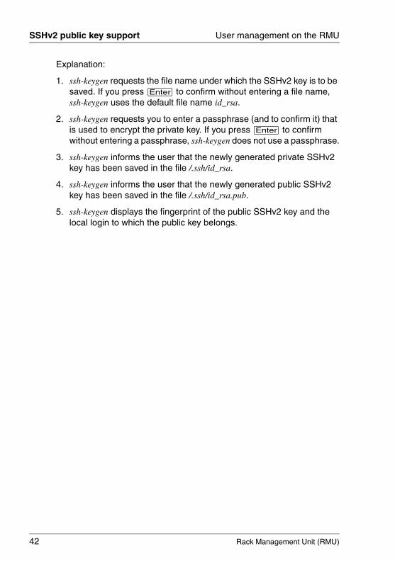
Explanation:
1. ssh-keygen requests the file name under which the SSHv2 key is to be saved. If you press [Enter] to confirm without entering a file name, ssh-keygen uses the default file name id_rsa.
2. ssh-keygen requests you to enter a passphrase (and to confirm it) that is used to encrypt the private key. If you press [Enter] to confirm without entering a passphrase, ssh-keygen does not use a passphrase.
3. ssh-keygen informs the user that the newly generated private SSHv2 key has been saved in the file /.ssh/id_rsa.
4. ssh-keygen informs the user that the newly generated public SSHv2 key has been saved in the file /.ssh/id_rsa.pub.
5. ssh-keygen displays the fingerprint of the public SSHv2 key and the local login to which the public key belongs.
Rack Management Unit (RMU) 43
User management on the RMU SSHv2 public key support
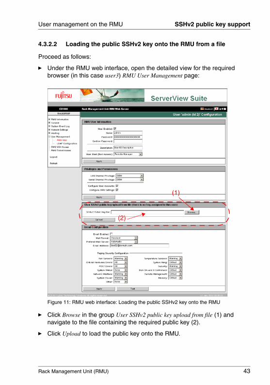
4.3.2.2 Loading the public SSHv2 key onto the RMU from a file
Proceed as follows:
Ê Under the RMU web interface, open the detailed view for the required browser (in this case user3) RMU User Management page:
Figure 11: RMU web interface: Loading the public SSHv2 key onto the RMU
Ê Click Browse in the group User SSHv2 public key upload from file (1) and navigate to the file containing the required public key (2).
Ê Click Upload to load the public key onto the RMU.
(1)
(2)
44 Rack Management Unit (RMU)
SSHv2 public key support User management on the RMU
© c
ogni
tas.
Ges
ells
chft
für
Tech
nik-
Dok
umen
tatio
n m
bH 2
009
Pfa
d: A
:\Ben
_Nev
is_R
MU
\Han
dbuc
h\en
\rm
u-en
.k04
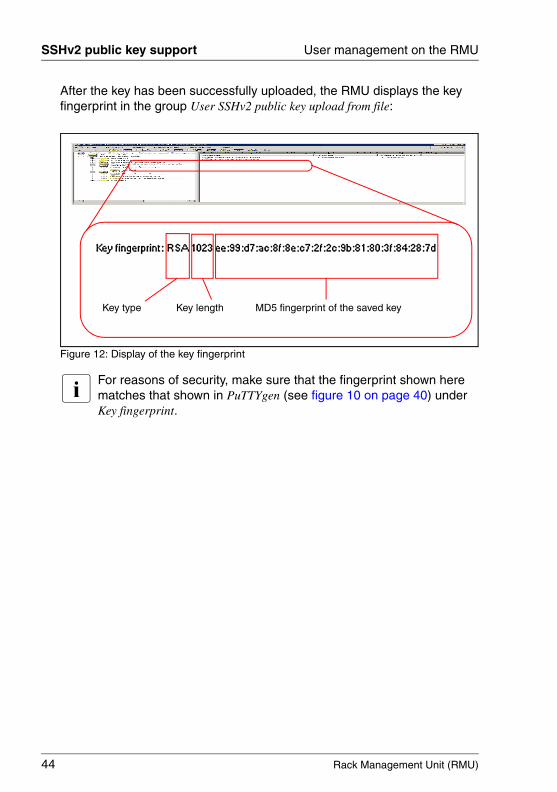
After the key has been successfully uploaded, the RMU displays the key fingerprint in the group User SSHv2 public key upload from file:
Figure 12: Display of the key fingerprint
I For reasons of security, make sure that the fingerprint shown here matches that shown in PuTTYgen (see figure 10 on page 40) under Key fingerprint.
Key lengthKey type MD5 fingerprint of the saved key
Rack Management Unit (RMU) 45
User management on the RMU SSHv2 public key support
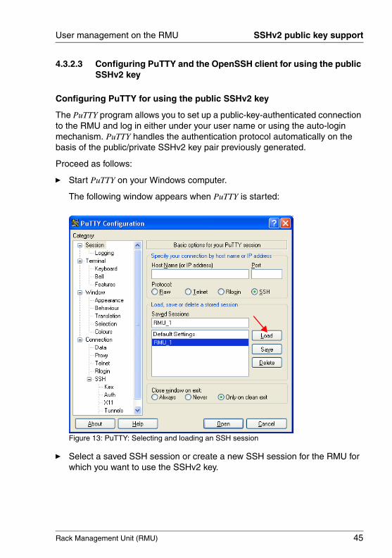
4.3.2.3 Configuring PuTTY and the OpenSSH client for using the public SSHv2 key
Configuring PuTTY for using the public SSHv2 key
The PuTTY program allows you to set up a public-key-authenticated connection to the RMU and log in either under your user name or using the auto-login mechanism. PuTTY handles the authentication protocol automatically on the basis of the public/private SSHv2 key pair previously generated.
Proceed as follows:
Ê Start PuTTY on your Windows computer.
The following window appears when PuTTY is started:
Figure 13: PuTTY: Selecting and loading an SSH session
Ê Select a saved SSH session or create a new SSH session for the RMU for which you want to use the SSHv2 key.
46 Rack Management Unit (RMU)
SSHv2 public key support User management on the RMU
© c
ogni
tas.
Ges
ells
chft
für
Tech
nik-
Dok
umen
tatio
n m
bH 2
009
Pfa
d: A
:\Ben
_Nev
is_R
MU
\Han
dbuc
h\en
\rm
u-en
.k04
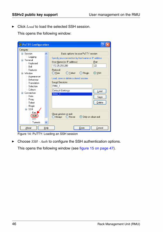
Ê Click Load to load the selected SSH session.
This opens the following window:
Figure 14: PuTTY: Loading an SSH session
Ê Choose SSH - Auth to configure the SSH authentication options.
This opens the following window (see figure 15 on page 47).
Rack Management Unit (RMU) 47
User management on the RMU SSHv2 public key support
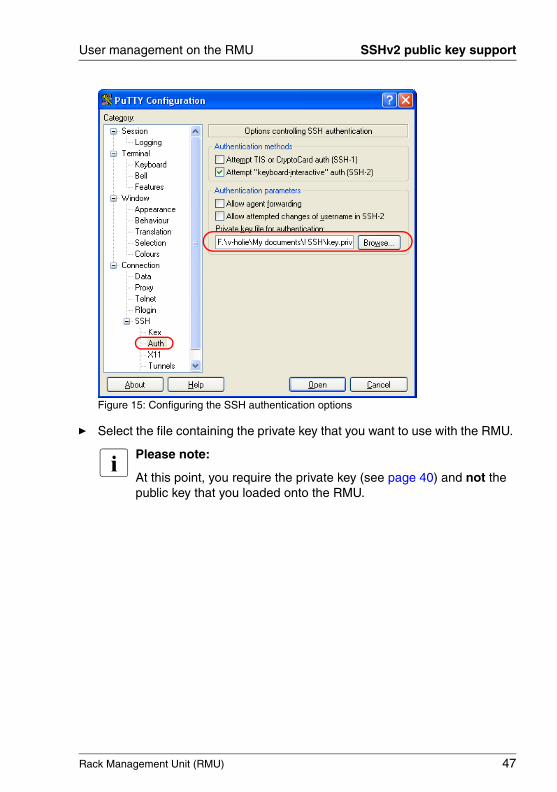
Figure 15: Configuring the SSH authentication options
Ê Select the file containing the private key that you want to use with the RMU.
I Please note:
At this point, you require the private key (see page 40) and not the public key that you loaded onto the RMU.
48 Rack Management Unit (RMU)
SSHv2 public key support User management on the RMU
© c
ogni
tas.
Ges
ells
chft
für
Tech
nik-
Dok
umen
tatio
n m
bH 2
009
Pfa
d: A
:\Ben
_Nev
is_R
MU
\Han
dbuc
h\en
\rm
u-en
.k04
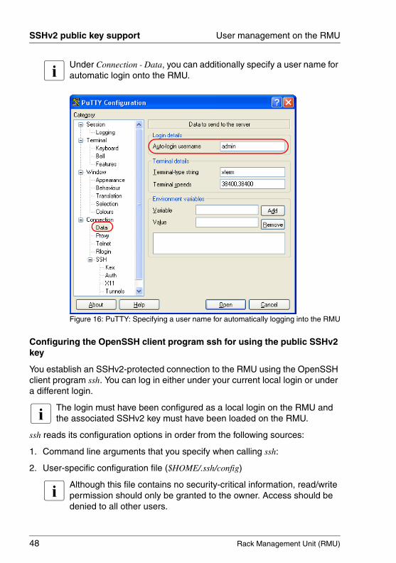
I Under Connection - Data, you can additionally specify a user name for automatic login onto the RMU.
Figure 16: PuTTY: Specifying a user name for automatically logging into the RMU
Configuring the OpenSSH client program ssh for using the public SSHv2 key
You establish an SSHv2-protected connection to the RMU using the OpenSSH client program ssh. You can log in either under your current local login or under a different login.
I The login must have been configured as a local login on the RMU and the associated SSHv2 key must have been loaded on the RMU.
ssh reads its configuration options in order from the following sources:
1. Command line arguments that you specify when calling ssh:
2. User-specific configuration file ($HOME/.ssh/config)
I Although this file contains no security-critical information, read/write permission should only be granted to the owner. Access should be denied to all other users.
Rack Management Unit (RMU) 49
User management on the RMU SSHv2 public key support
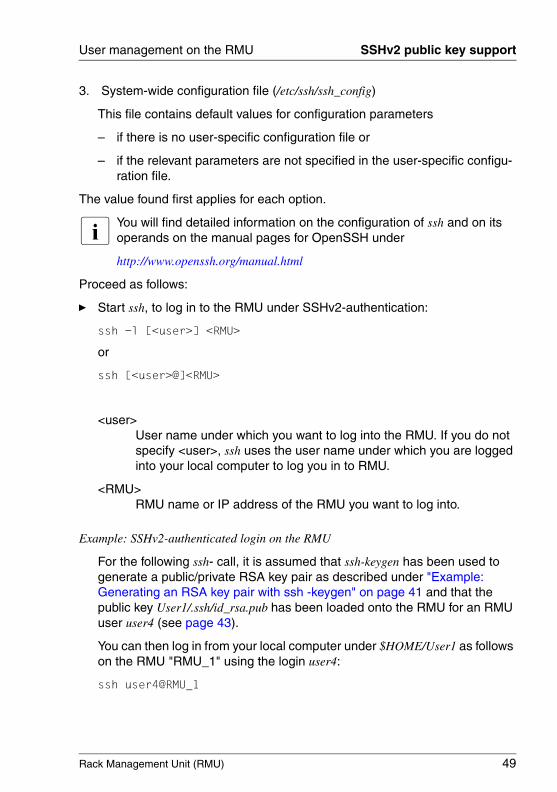
3. System-wide configuration file (/etc/ssh/ssh_config)
This file contains default values for configuration parameters
– if there is no user-specific configuration file or
– if the relevant parameters are not specified in the user-specific configu-ration file.
The value found first applies for each option.
I You will find detailed information on the configuration of ssh and on its operands on the manual pages for OpenSSH under
http://www.openssh.org/manual.html
Proceed as follows:
Ê Start ssh, to log in to the RMU under SSHv2-authentication:
ssh -l [<user>] <RMU>
or
ssh [<user>@]<RMU>
<user>User name under which you want to log into the RMU. If you do not specify <user>, ssh uses the user name under which you are logged into your local computer to log you in to RMU.
<RMU> RMU name or IP address of the RMU you want to log into.
Example: SSHv2-authenticated login on the RMU
For the following ssh- call, it is assumed that ssh-keygen has been used to generate a public/private RSA key pair as described under "Example: Generating an RSA key pair with ssh -keygen" on page 41 and that the public key User1/.ssh/id_rsa.pub has been loaded onto the RMU for an RMU user user4 (see page 43).
You can then log in from your local computer under $HOME/User1 as follows on the RMU "RMU_1" using the login user4:
ssh user4@RMU_1
50 Rack Management Unit (RMU)
SSHv2 public key support User management on the RMU
© c
ogni
tas.
Ges
ells
chft
für
Tech
nik-
Dok
umen
tatio
n m
bH 2
009
Pfa
d: A
:\Ben
_Nev
is_R
MU
\Han
dbuc
h\en
\rm
u-en
.k04
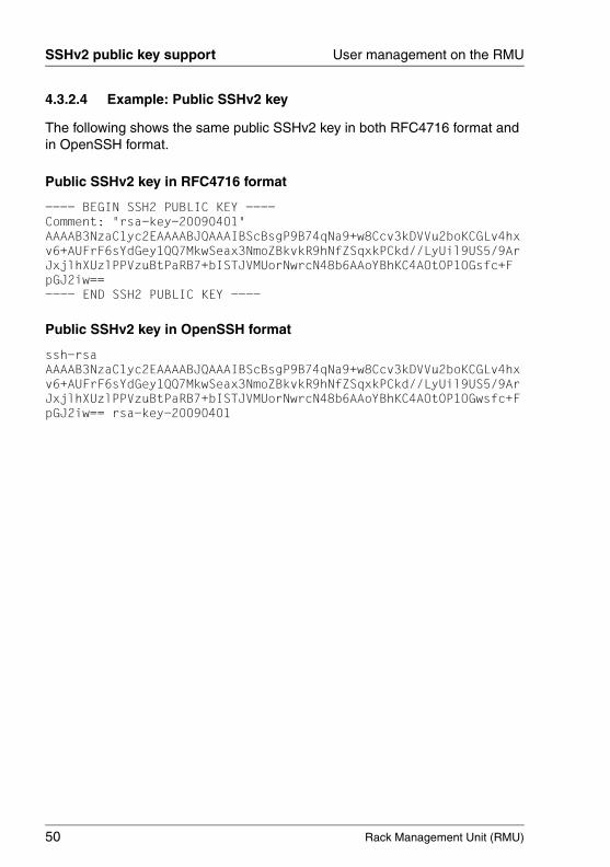
4.3.2.4 Example: Public SSHv2 key
The following shows the same public SSHv2 key in both RFC4716 format and in OpenSSH format.
Public SSHv2 key in RFC4716 format
---- BEGIN SSH2 PUBLIC KEY ----Comment: "rsa-key-20090401"AAAAB3NzaC1yc2EAAAABJQAAAIBScBsgP9B74qNa9+w8Ccv3kDVVu2boKCGLv4hxv6+AUFrF6sYdGey1QQ7MkwSeax3NmoZBkvkR9hNfZSqxkPCkd//LyUil9US5/9ArJxjlhXUzlPPVzuBtPaRB7+bISTJVMUorNwrcN48b6AAoYBhKC4AOtOP1OGsfc+FpGJ2iw==---- END SSH2 PUBLIC KEY ----
Public SSHv2 key in OpenSSH format
ssh-rsa AAAAB3NzaC1yc2EAAAABJQAAAIBScBsgP9B74qNa9+w8Ccv3kDVVu2boKCGLv4hxv6+AUFrF6sYdGey1QQ7MkwSeax3NmoZBkvkR9hNfZSqxkPCkd//LyUil9US5/9ArJxjlhXUzlPPVzuBtPaRB7+bISTJVMUorNwrcN48b6AAoYBhKC4AOtOP1OGwsfc+FpGJ2iw== rsa-key-20090401

Rack Management Unit (RMU) 51
User management on the RMU ... globally via a directory service
4.4 Global user management for the RMU
The global user IDs for the RMU are managed centrally using an LDAP directory service.
The following directory services are currently supported for RMU user management:
– Microsoft® Active Directory – Novell® eDirectory – OpenLDAP
This section provides you with information about the following topics:
– Overview of global user management for the RMU
– Concept of global user management for the RMU using an LDAP directory service
– Configuring global RMU user management in the directory service (gener-ating the permissions structures specific to Ldap v1 / LDAP v2 in the directory service).
– Global RMU user management via Microsoft Active Directory
– Global RMU user management via Novell eDirectory
– Global RMU user management via OpenLDAP
I Alongside the measures described in this section which you perform in the directory service, global user management also requires you to configure the local LDAP settings at the RMU.
You can configure the local LDAP settings at the RMU web interface (see page page 211)
52 Rack Management Unit (RMU)
... globally via a directory service User management on the RMU
© c
ogni
tas.
Ges
ells
chft
für
Tech
nik-
Dok
umen
tatio
n m
bH 2
009
Pfa
d: A
:\Ben
_Nev
is_R
MU
\Han
dbuc
h\en
\rm
u-en
.k04
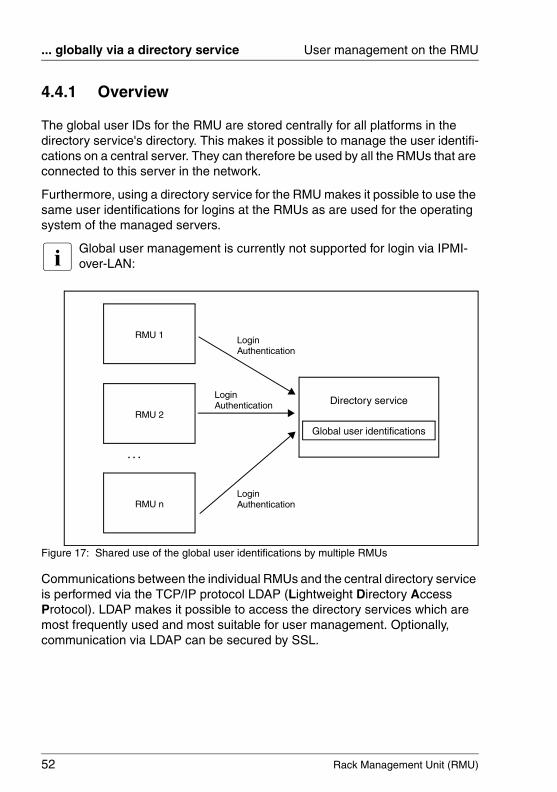
4.4.1 Overview
The global user IDs for the RMU are stored centrally for all platforms in the directory service's directory. This makes it possible to manage the user identifi-cations on a central server. They can therefore be used by all the RMUs that are connected to this server in the network.
Furthermore, using a directory service for the RMU makes it possible to use the same user identifications for logins at the RMUs as are used for the operating system of the managed servers.
I Global user management is currently not supported for login via IPMI-over-LAN:
Figure 17: Shared use of the global user identifications by multiple RMUs
Communications between the individual RMUs and the central directory service is performed via the TCP/IP protocol LDAP (Lightweight Directory Access Protocol). LDAP makes it possible to access the directory services which are most frequently used and most suitable for user management. Optionally, communication via LDAP can be secured by SSL.
RMU 1
RMU 2
RMU n
. . .
Directory service
Global user identifications
LoginAuthentication
LoginAuthentication
LoginAuthentication
Rack Management Unit (RMU) 53
User management on the RMU ... globally via a directory service
4.4.2 RMU user management via an LDAP directory service (concept)
I The concept of directory service-based, global RMU user management described below applies equally to the directory services Microsoft Active Directory, Novell eDirectory and OpenLDAP. The figures are based on the example of the Active Directory Users and Computers console in the Microsoft Active Directory user interface.
I The following characters are reserved as metacharacters for search strings in LDAP: *, \, &, (, ), |, !, =, <, >, ~, :
You must therefore not use these characters as components of Relative Distinguished Names (RDN).
4.4.2.1 Global RMU user management using permission groups and roles
Global RMU user management via an LDAP directory server requires no extension to the standard directory server schema. Instead, all the information that is relevant for the RMU, including the user permissions (privileges), is provided via additional LDAP groups and organizational units (OUs) which are combined in separate OUs in a domain of the LDAP directory server (see figure 19 on page 56).
RMU users obtain their privileges by being assigned a role (user role) declared in the organizational unit (OU) SVS or by membership of a group of the OU iRMCgroups.
I If both the OU SVS and the structure iRMCgroups are defined in the directory service, the login data of the user is first compared with the entries in SVS to authenticate a user. If no matching entry is found there, an attempt is made to find a match in the entries in iRMCgroups. In either case, the first matching entry is relevant.

54 Rack Management Unit (RMU)
... globally via a directory service User management on the RMU
© c
ogni
tas.
Ges
ells
chft
für
Tech
nik-
Dok
umen
tatio
n m
bH 2
009
Pfa
d: A
:\Ben
_Nev
is_R
MU
\Han
dbuc
h\en
\rm
u-en
.k04
Assigning permissions with user roles (abbreviated to: roles)
Global user management on the RMU controls the assignment of permissions by means of user roles. In this case, each role defines a specific, task-oriented permission profile for activities on the RMU.
Several roles can be assigned to each user with the result that the permissions for this user are defined by the sum of the permissions of all the assigned roles.
figure 18 illustrates the concept of role-based assignment of user permissions with the roles Administrator, Maintenance, and Observer.
Figure 18: Role-based assignment of user permissions
The concept of user roles offers important advantages, including:
– The individual permissions do not need to be assigned to each user or user group individually. Instead, they are assigned to the user role.
– It is only necessary to adapt the permissions of the user role in the event that the permission structure changes.
Administrator Maintenance Observer
Mr. Miller Ms. Smith Mr. Baker
RMU SettingsUser Mgmnt. RMU Info
Rack Management Unit (RMU) 55
User management on the RMU ... globally via a directory service
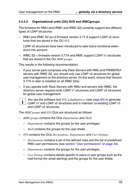
4.4.2.2 Organizational units (OU) SVS and iRMCgroups
The firmware for RMU (and iRMC and iRMC S2) currently support two different types of LDAP structures:
– RMU and iRMC S2 as of firmware version 3.77 A support LDAP v2 struc-tures that are stored in the OU SVS.
LDAP v2 structures have been introduced to take future functional exten-sions into account.
– iRMC S2 < firmware version 3.77A and iRMC support LDAP v1 structures that are stored in the OU iRMCgroups.
This results in the following recommendation:
– If your server park comprises only Rack Servers with RMU and PRIMERGY servers with iRMC S2, you should only use LDAP v2 structures for global user management on the directory server. (In this event, ensure that Version 3.77A or later is installed on all iRMC S2s).
– If you operate both Rack Servers with RMU and servers with iRMC, the directory server requires both LDAP v1 structures and LDAP v2 structures for global user management.
I You use the software tool SVS_LdapDeployer (see page 64) to generate LDAP v1 and LDAP v2 structures and to maintain co-existing LDAP v1 and LDAP v2 structures.
The iRMCgroups and SVS OUs are structured as follows:
– iRMCgroups contains the OUs Departments and Shell:
– Departments contains the groups for the user privileges.
– Shell contains the groups for the user shells.
– SVS contains the OUs Declarations, Departments and User Settings:
– Declarations contains a list of the defined roles and the list of predefined RMU user permissions (see section "User permissions" on page 34).
– Departments contains the groups for the user privileges.
– User Settings contains details specific to users or user groups such as the mail format (for email alerting) and the groups for the user shells.
56 Rack Management Unit (RMU)
... globally via a directory service User management on the RMU
© c
ogni
tas.
Ges
ells
chft
für
Tech
nik-
Dok
umen
tatio
n m
bH 2
009
Pfa
d: A
:\Ben
_Nev
is_R
MU
\Han
dbuc
h\en
\rm
u-en
.k04
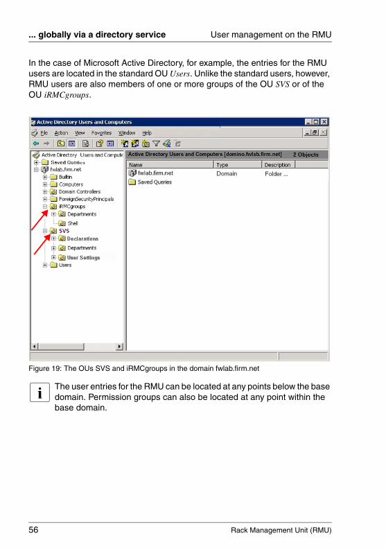
In the case of Microsoft Active Directory, for example, the entries for the RMU users are located in the standard OU Users. Unlike the standard users, however, RMU users are also members of one or more groups of the OU SVS or of the OU iRMCgroups.
Figure 19: The OUs SVS and iRMCgroups in the domain fwlab.firm.net
I The user entries for the RMU can be located at any points below the base domain. Permission groups can also be located at any point within the base domain.
Rack Management Unit (RMU) 57
User management on the RMU ... globally via a directory service
4.4.2.3 Cross-server, global user permissions
In large enterprises, the rack servers which are managed via RMU are usually assigned to different departments. Furthermore, the administrator permissions for the managed servers are also often assigned on a department-specific basis.
Departments are combined in the OU “Departments”
The OU Departments combines the rack servers which are managed by RMU to form a number of groups. These correspond to the departments in which the same user IDs and permissions apply. In figure 20 on page 58, for example, these are the departments DeptX, DeptY and Others.
The entry Others is optional, but recommended. Others is a predefined department name subsuming all those servers which do not belong to another department. There are no restrictions concerning the number of departments (OUs) listed under Departments.
I When configuring the directory service at the RMU via the RMU web interface (see page 211), you specify the name of the department to which the managed server with the relevant RMU belongs. If there is no department of this name in the LDAP directory then the permissions present in the Others department are used.
figure 20 on page 58 presents an example of this type of organizational structure on the basis of Active Directory Users and Computers.

58 Rack Management Unit (RMU)
... globally via a directory service User management on the RMU
© c
ogni
tas.
Ges
ells
chft
für
Tech
nik-
Dok
umen
tatio
n m
bH 2
009
Pfa
d: A
:\Ben
_Nev
is_R
MU
\Han
dbuc
h\en
\rm
u-en
.k04
Figure 20: Organizational structure of the domain fwlab.firm.net
Rack Management Unit (RMU) 59
User management on the RMU ... globally via a directory service
4.4.2.4 iRMCgroups: Permission profiles are defined via permission groups
The associated permission groups (security groups) are listed directly below each department (figure 20 on page 58). There are no restrictions concerning the number of permission groups. The names of the permission groups can be chosen as required subject to certain syntactic requirements imposed by the employed directory service. Every permission group defines a specific permission profile which applies to all the users who belong to the relevant permission group.
V CAUTION!
Make sure that no user simultaneously belongs to more than one permission group in one and the same department. (If a user belongs to more than one permission group in the same department then the first result returned by an LDAP query always apples.)
I The permission groups in global RMU user management also include the channel-specific permission groups (see page 34). For detailed infor-mation on the individual user permissions, see section "User permis-sions" on page 34.
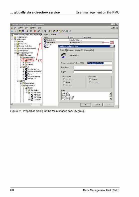
If, for example, you click a department (e.g. DeptX) (1) in the hierarchy tree in Active Directory Users and Computers (see figure 21 on page 60) then the permission groups (security groups) defined for this department are listed in the display area (here: DeptX).
You can click on one of the displayed security groups (2) to open the Properties dialog for this security group (here: Maintenance). The associated permission is listed under Notes using the following syntax:
V CAUTION!
You must not change the user profile in the Notes field, as this would make it impossible to log in. Roles can only be changed using the SVS_LdapDeployer (see page 64).
LAN: OEM | Administrator | Operator | User | None
Serial: OEM | Administrator | Operator | User | None
UserAccounts: On | Off
RMUsettings: On | Off
60 Rack Management Unit (RMU)
... globally via a directory service User management on the RMU
© c
ogni
tas.
Ges
ells
chft
für
Tech
nik-
Dok
umen
tatio
n m
bH 2
009
Pfa
d: A
:\Ben
_Nev
is_R
MU
\Han
dbuc
h\en
\rm
u-en
.k04
Figure 21: Properties dialog for the Maintenance security group
(1)
(2)
Rack Management Unit (RMU) 61
User management on the RMU ... globally via a directory service
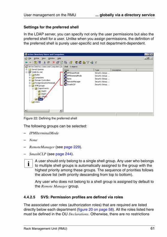
Settings for the preferred shell
In the LDAP server, you can specify not only the user permissions but also the preferred shell for a user. Unlike when you assign permissions, the definition of the preferred shell is purely user-specific and not department-dependent.
Figure 22: Defining the preferred shell
The following groups can be selected:
– IPMIterminalMode
– None
– RemoteManager (see page 229).
– SmashCLP (see page 244).
I A user should only belong to a single shell group. Any user who belongs to multiple shell groups is automatically assigned to the group with the highest priority among these groups. The sequence of priorities follows the above list (with priority descending from top to bottom).
Any user who does not belong to a shell group is assigned by default to the Remote Manager group.
4.4.2.5 SVS: Permission profiles are defined via roles
The associated user roles (authorization roles) that are required are listed directly below each department (figure 20 on page 58). All the roles listed here must be defined in the OU Declarations. Otherwise, there are no restrictions
62 Rack Management Unit (RMU)
... globally via a directory service User management on the RMU
© c
ogni
tas.
Ges
ells
chft
für
Tech
nik-
Dok
umen
tatio
n m
bH 2
009
Pfa
d: A
:\Ben
_Nev
is_R
MU
\Han
dbuc
h\en
\rm
u-en
.k04
concerning the number of roles. The names of the roles can be chosen as required subject to certain syntactic requirements imposed by the employed directory service. Each authorization role defines a specific, task-oriented permission profile for activities on the RMU.
I The alert roles are listed as well as the authorization roles. Each alert role defines a specific alerting profile for email alerting (see section "Configuring email alerting to global RMU users" on page 124).
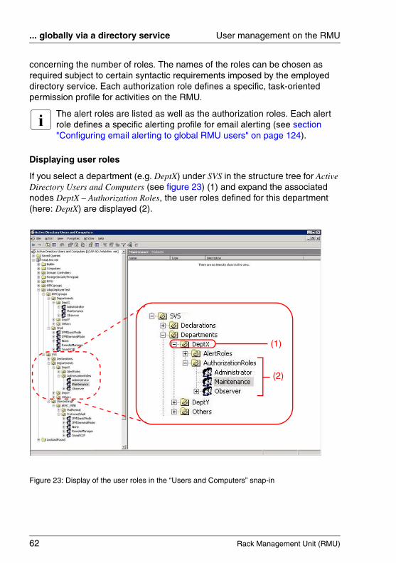
Displaying user roles
If you select a department (e.g. DeptX) under SVS in the structure tree for Active Directory Users and Computers (see figure 23) (1) and expand the associated nodes DeptX – Authorization Roles, the user roles defined for this department (here: DeptX) are displayed (2).
Figure 23: Display of the user roles in the “Users and Computers” snap-in
(1)
(2)

Rack Management Unit (RMU) 63
User management on the RMU ... globally via a directory service
Displaying permission groups to which a user is assigned
If you select a user (e.g. Obs1) under Users in the structure tree for Active Directory Users and Computers (see figure 24) (1) and open the Properties dialog box for this user by choosing Properties – Members from the context menu, the permission groups to which the user belongs (here: Obs1) are displayed in the Members tab (2).
Figure 24: Properties dialog box for the user Obs1
(1)
(2)
64 Rack Management Unit (RMU)
... globally via a directory service User management on the RMU
© c
ogni
tas.
Ges
ells
chft
für
Tech
nik-
Dok
umen
tatio
n m
bH 2
009
Pfa
d: A
:\Ben
_Nev
is_R
MU
\Han
dbuc
h\en
\rm
u-en
.k04
4.4.3 SVS_LdapDeployer - Generating, maintaining and deleting the “SVS” and “iRMCgroups” structures
To allow global RMU user management to be able to handled using a directory service, the structure(s) (OU) SVS and iRMCgroups must be created in the LDAP directory service.
You use the SVS_LdapDeployer to generate and modify the structures SVS and iRMCgroups. The SVS_LdapDeployer is a Java archive (SVS_LdapDeployer.jar) provided for Download under http://support.ts.fujitsu.com/com/support/downloads.html.
This section describes:
– The configuration file of the SVS_LdapDeployer
– SVS_LdapDeployer
– The commands and options of the SVS_LdapDeployer
– Typical application scenarios
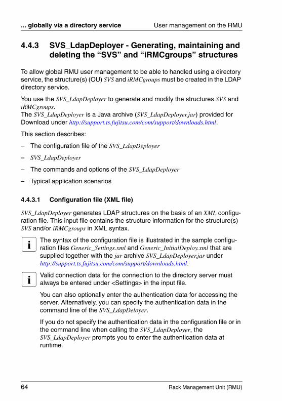
4.4.3.1 Configuration file (XML file)
SVS_LdapDeployer generates LDAP structures on the basis of an XML configu-ration file. This input file contains the structure information for the structure(s) SVS and/or iRMCgroups in XML syntax.
I The syntax of the configuration file is illustrated in the sample configu-ration files Generic_Settings.xml and Generic_InitialDeploy.xml that are supplied together with the jar archive SVS_LdapDeployer.jar under http://support.ts.fujitsu.com/com/support/downloads.html.
I Valid connection data for the connection to the directory server must always be entered under <Settings> in the input file.
You can also optionally enter the authentication data for accessing the server. Alternatively, you can specify the authentication data in the command line of the SVS_LdapDeloyer.
If you do not specify the authentication data in the configuration file or in the command line when calling the SVS_LdapDeployer, the SVS_LdapDeployer prompts you to enter the authentication data at runtime.
Rack Management Unit (RMU) 65
User management on the RMU ... globally via a directory service
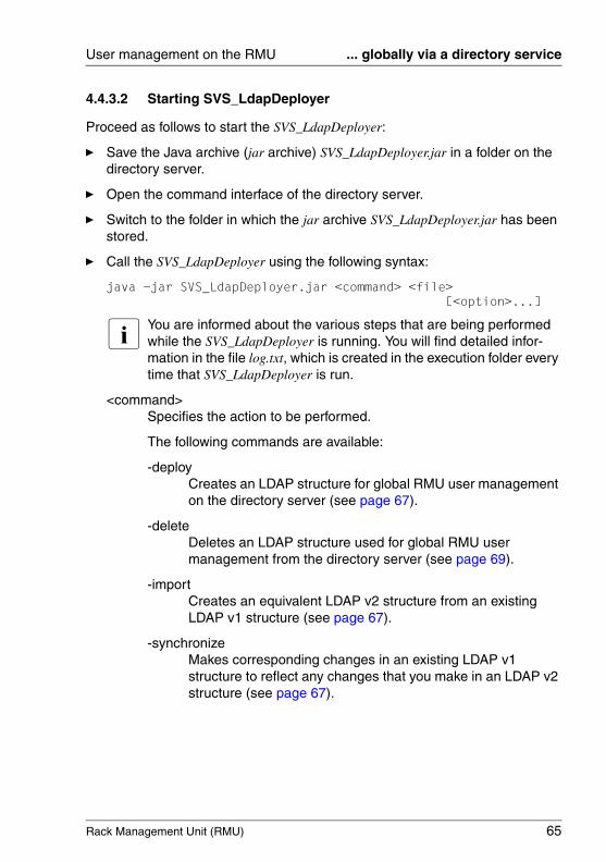
4.4.3.2 Starting SVS_LdapDeployer
Proceed as follows to start the SVS_LdapDeployer:
Ê Save the Java archive (jar archive) SVS_LdapDeployer.jar in a folder on the directory server.
Ê Open the command interface of the directory server.
Ê Switch to the folder in which the jar archive SVS_LdapDeployer.jar has been stored.
Ê Call the SVS_LdapDeployer using the following syntax:
java -jar SVS_LdapDeployer.jar <command> <file> [<option>...]
I You are informed about the various steps that are being performed while the SVS_LdapDeployer is running. You will find detailed infor-mation in the file log.txt, which is created in the execution folder every time that SVS_LdapDeployer is run.
<command>Specifies the action to be performed.
The following commands are available:
-deployCreates an LDAP structure for global RMU user management on the directory server (see page 67).
-deleteDeletes an LDAP structure used for global RMU user management from the directory server (see page 69).
-importCreates an equivalent LDAP v2 structure from an existing LDAP v1 structure (see page 67).
-synchronizeMakes corresponding changes in an existing LDAP v1 structure to reflect any changes that you make in an LDAP v2 structure (see page 67).
66 Rack Management Unit (RMU)
... globally via a directory service User management on the RMU
© c
ogni
tas.
Ges
ells
chft
für
Tech
nik-
Dok
umen
tatio
n m
bH 2
009
Pfa
d: A
:\Ben
_Nev
is_R
MU
\Han
dbuc
h\en
\rm
u-en
.k04
<file>The configuration file (.xml) used as an input file by SVS_LdapDeploy. This configuration file contains the structure information for the structure(s) SVS and/or iRMCgroups in XML syntax.
I The syntax of the configuration file is illustrated in the sample configuration files Generic_Settings.xml and Generic_InitialDeploy.xml that are supplied together with the jar archive SVS_LdapDeployer.jar .
<option> [<option> ...]Option(s) that control execution of the specified command.
The following sections describe in detail the individual commands available in SVS_LdapDeployer together with the associated options.
I The SVS_LdapDeployer generates all the required subtrees including all the groups but not the relations between users and groups.
You create and assign user entries to groups by means of the corre-sponding tools in the employed directory service after generating the OUs SVS and/or iRMCgroups in the directory service.
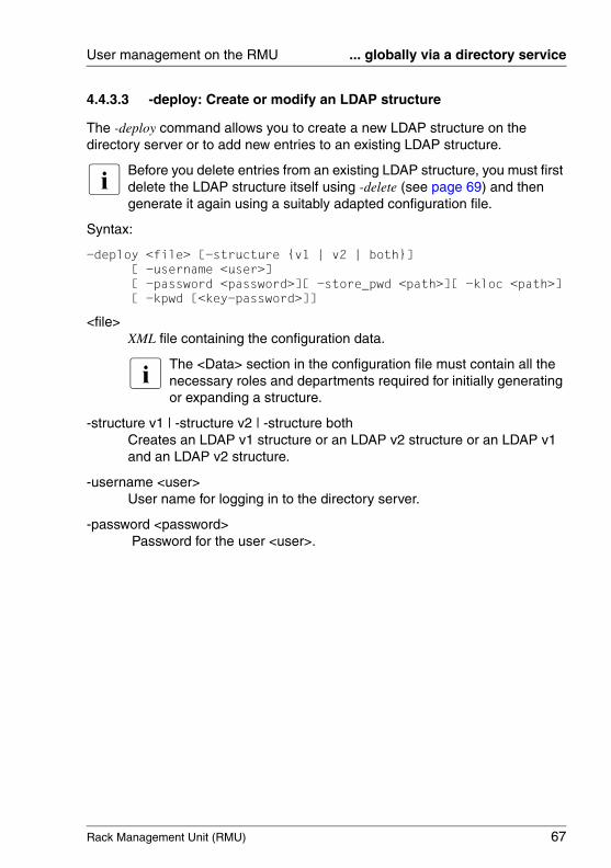
Rack Management Unit (RMU) 67
User management on the RMU ... globally via a directory service
4.4.3.3 -deploy: Create or modify an LDAP structure
The -deploy command allows you to create a new LDAP structure on the directory server or to add new entries to an existing LDAP structure.
I Before you delete entries from an existing LDAP structure, you must first delete the LDAP structure itself using -delete (see page 69) and then generate it again using a suitably adapted configuration file.
Syntax:
-deploy <file> [-structure {v1 | v2 | both}][ -username <user>][ -password <password>][ -store_pwd <path>][ -kloc <path>][ -kpwd [<key-password>]]
<file>XML file containing the configuration data.
I The <Data> section in the configuration file must contain all the necessary roles and departments required for initially generating or expanding a structure.
-structure v1 | -structure v2 | -structure bothCreates an LDAP v1 structure or an LDAP v2 structure or an LDAP v1 and an LDAP v2 structure.
-username <user>User name for logging in to the directory server.
-password <password> Password for the user <user>.
68 Rack Management Unit (RMU)
... globally via a directory service User management on the RMU
© c
ogni
tas.
Ges
ells
chft
für
Tech
nik-
Dok
umen
tatio
n m
bH 2
009
Pfa
d: A
:\Ben
_Nev
is_R
MU
\Han
dbuc
h\en
\rm
u-en
.k04
-store_pwd Encrypts the password <password> using a randomly generated key and saves the encrypted password in the configuration file after -deploy has been executed successfully. By default, the randomly generated key is stored in the folder in which the SVS_LdapDeployer is executed.
V CAUTION!
You should save the randomly generated key in a safe place. If the predefined target folder is not adequate for your security needs, or if the folder in which the key is saved can also be accessed by other users, use the options -kloc and -kpwd to save the key securely.
-kloc <path>Saves the randomly generated key under <path>. If you do not specify this option, the key is saved in the folder in which SVS_LdapDeployer is executed.
-kpwd [<password>]Specifies a password to protect the randomly generated key.If you do not specify <password>, the password is automatically generated on the basis of a snapshot of the current runtime environment.
Rack Management Unit (RMU) 69
User management on the RMU ... globally via a directory service
4.4.3.4 -delete: Deleting an LDAP structure
The -delete command allows you to remove an LDAP structure from the directory server.
Syntax:
-delete <file> [-structure {v1 | v2 | both}][ -username <user>][ -password <password>][ -store_pwd <path>][ -kloc <path>][ -kpwd [<key-password>]]
<file>XML file that specifies the structure to be deleted.
-structure v1 | -structure v2 | -structure bothDeletes an LDAP v1 structure or an LDAP v2 structure or an LDAP v1 and an LDAP v2 structure.
-username <user>User name for logging in to the directory server.
-password <password> Password for the user <user>.
-stor_pwd Encrypts the password <password> using a randomly generated key and saves the encrypted password in the configuration file after -delete has been executed successfully. By default, the randomly generated key is stored in the folder in which the SVS_LdapDeployer is executed.
V CAUTION!
You should save the randomly generated key in a safe place. If the predefined target folder is not adequate for your security needs, or if the folder in which the key is saved can also be accessed by other users, use the options kloc and -kpwd to save the key securely.
-kloc <path>Saves the randomly generated key under <path>. If you do not specify this option, the key is saved in the folder in which SVS_LdapDeployer is executed.
-kpwd [<password>]Specifies a password to protect the randomly generated key.If you do not specify <password>, the password is automatically generated on the basis of a snapshot of the current runtime environment.

70 Rack Management Unit (RMU)
... globally via a directory service User management on the RMU
© c
ogni
tas.
Ges
ells
chft
für
Tech
nik-
Dok
umen
tatio
n m
bH 2
009
Pfa
d: A
:\Ben
_Nev
is_R
MU
\Han
dbuc
h\en
\rm
u-en
.k04
4.4.3.5 -import: Importing an LDAP v1 structure into an LDAP v2 structure
The -import command allows you to generate an equivalent LDAP v2 structure on the directory server from an existing LDAP V1 structure.
Syntax:
-import <file>[ -username <user>][ -password <password>][ -store_pwd <path>][ -kloc <path>][ -kpwd [<key-password>]]
<file>XML file that specifies the structure to be imported.
-username <user>User name for logging in to the directory server.
-password <password> Password for the user <user>.
-stor_pwd Encrypts the password <password> using a randomly generated key and saves the encrypted password in the configuration file after -import has been executed successfully. By default, the randomly generated key is stored in the folder in which the SVS_LdapDeployer is executed.
V CAUTION!
You should save the randomly generated key in a safe place. If the predefined target folder is not adequate for your security needs, or if the folder in which the key is saved can also be accessed by other users, use the options kloc and -kpwd to save the key securely.
-kloc <path>Saves the randomly generated key under <path>. If you do not specify this option, the key is saved in the folder in which SVS_LdapDeployer is executed.
-kpwd [<password>]Specifies a password to protect the randomly generated key.If you do not specify <password>, the password is automatically generated on the basis of a snapshot of the current runtime environment.
Rack Management Unit (RMU) 71
User management on the RMU ... globally via a directory service
4.4.3.6 -synchronize: Synchronizing changes made in an LDAP v2 structure with an LDAP v1 structure
In a mixed configuration using LDAP v1 and LDAP v2 structures, you can use the -synchronize command to synchronize changes you have made in an LDAP v2 structure with an existing LDAP v1 structure.
I Always make your changes in the LDAP v2 structure!
Syntax:
-import <file>[ -username <user>][ -password <password>][ -store_pwd <path>][ -kloc <path>][ -kpwd [<key-password>]]
<file>XML file that specifies the structure to be imported.
-username <user>User name for logging in to the directory server.
-password <password> Password for the user <user>.
-stor_pwd Encrypts the password <password> using a randomly generated key and saves the encrypted password in the configuration file after -synchronize has been executed successfully. By default, the randomly generated key is stored in the folder in which the SVS_LdapDeployer is executed.
V CAUTION!
You should save the randomly generated key in a safe place. If the predefined target folder is not adequate for your security needs, or if the folder in which the key is saved can also be accessed by other users, use the options -kloc and -kpwd to save the key securely.
-kloc <path>Saves the randomly generated key under <path>. If you do not specify this option, the key is saved in the folder in which SVS_LdapDeployer is executed.
72 Rack Management Unit (RMU)
... globally via a directory service User management on the RMU
© c
ogni
tas.
Ges
ells
chft
für
Tech
nik-
Dok
umen
tatio
n m
bH 2
009
Pfa
d: A
:\Ben
_Nev
is_R
MU
\Han
dbuc
h\en
\rm
u-en
.k04
-kpwd [<password>]Specifies a password to protect the randomly generated key.If you do not specify <password>, the password is automatically generated on the basis of a snapshot of the current runtime environment.
Rack Management Unit (RMU) 73
User management on the RMU ... globally via a directory service
4.4.4 Typical application scenarios
Four typical scenarios for using SVS_LdapDeployer are described below.
4.4.4.1 Performing an initial configuration in which LDAP v1 and LDAP v2 structures coexist
You wish to set up global user management for RMU for the first time. In order to do this, you require both LDAP v1 and LDAP v2 structures.
Recommended method:
1. Generate the Department definitions for LDAP v1 and LDAP v2 structures (iRMCgroups and SVS):
java -jar SVS_LdapDeployer.jar -deploy myInitialDeploy.xml -structure both
2. Any changes you make in the future should then only be made in the LDAP v2 structure and then transferred to the LDAP v1 structure using the -synchronize command (see page 71):
java -jar SVS_LdapDeployer.jar -synchronize mySettings.xml
4.4.4.2 Importing an LDAP v1 structure into an LDAP v2 structure
You are already operating global user management for iRMC and/or iRMC S2 on the basis of LDAP v1. In future, you additionally wish to use global user management for RMU using an LDAP v2 structure.
Recommended method:
1. Import (convert) an existing LDAP v1 structure (iRMCgroups) into an LDAP v2 structure (SVS). Both structures are to coexist.
java -jar SVS_LdapDeployer.jar -import mySettings.xml
This statement copies department definitions and the assignment of users to permission groups from the existing LDAP v1 structure into a new LDAP v2 structure.
2. Any changes you make in the future should then only be made in the LDAP v2 structure and then transferred to the LDAP v1 structure using the -synchronize command (see page 71):
java -jar SVS_LdapDeployer.jar -synchronize mySettings.xml

74 Rack Management Unit (RMU)
... globally via a directory service User management on the RMU
© c
ogni
tas.
Ges
ells
chft
für
Tech
nik-
Dok
umen
tatio
n m
bH 2
009
Pfa
d: A
:\Ben
_Nev
is_R
MU
\Han
dbuc
h\en
\rm
u-en
.k04
4.4.4.3 Re-generating or expanding an LDAP v2 structure
You wish to re-generate an LDAP v2 structure or expand an existing LDAP v2 structure.
Recommended method:
java -jar SVS_LdapDeployer.jar -deploy myInitialDeploy.xml -structure -structure v2
or
java -jar SVS_LdapDeployer.jar -deploy myInitialDeploy.xml
4.4.4.4 Re-generating an LDAP v2 structure and prompting for and saving authentication data
You wish to re-generate an LDAP v2 structure. The authentication data is to be provided and saved using the command line.
Recommended method:
java -jar SVS_LdapDeployer.jar -deploy myInitialDeploy.xml-store_pwd -username admin -password admin
I After the login data has been saved, you can connect to the directory server using SVS_LdapDeployer without specifying a user name and password. The SVS_LdapDeployer then uses the values stored in the XML configuration file, provided that these are available. SVS_LdapDeployer can only use a saved password if it can decrypt it. This requires you to execute SVS_LdapDeployer in the same runtime environment that applied for the previous call with -store_pwd (see page 68). In this context, “the same runtime environment” means “the same the user on the same computer” or “a user with permission to access the folder under which they key is stored (-kloc option, see page 68)”.
I You can also use user accounts that have already been saved when you call SVS_LdapDeployer in the future. Furthermore, other authentication data can also be used temporarily by explicitly specifying the data in the command line or when requested to do so by SVS_LdapDeployer.

Rack Management Unit (RMU) 75
User management on the RMU ... globally via Active Directory
4.4.5 RMU user management via Microsoft Active Directory
This section describes how you integrate RMU user management in Microsoft Active Directory.
I Prerequisite:
An LDAP v1 and/or an LDAP v2 structure has already been generated in the Active Directory service (see section "SVS_LdapDeployer - Gener-ating, maintaining and deleting the “SVS” and “iRMCgroups” structures" on page 64).
You must perform the following steps to integrate RMU user management in Microsoft Active Directory:
1. Assign RMU users to RMU user groups in Active Directory.
2. Configure RMU LDAP/SSL access at the Active Directory server.

76 Rack Management Unit (RMU)
... globally via Active Directory User management on the RMU
© c
ogni
tas.
Ges
ells
chft
für
Tech
nik-
Dok
umen
tatio
n m
bH 2
009
Pfa
d: A
:\Ben
_Nev
is_R
MU
\Han
dbuc
h\en
\rm
u-en
.k04
4.4.5.1 Configuring RMU LDAP/SSL access at the Active Directory server
I The RMU-LDAP integration uses the SSL implementation developed by Eric Young on the basis of the OpenSSL Project. A reproduction of the SSL copyright can be found on page 132.
An RSA certificate is required before RMU can use LDAP via SSL.
The following steps are involved in configuring LDAP access:
1. Install an Enterprise CA
2. Generate an RSA certificate for the domain controller.
3. Install the RSA certificate on the server
Installing the Enterprise CA
I A CA is a “certification authority for certificates”. An Enterprise CA (certi-fication authority for enterprises) can be installed on the domain controller itself or on another server.
Installation directly on the CA is simpler since fewer steps are required than when installing on another server.
Below is a description of how to install the Enterprise CA on a server other than the domain controller.
I To install and configure Enterprise CA successfully, you require an Active Directory environment and an installed IIS (Internet Information Services).
Proceed as follows to install an Enterprise CA:
Ê In the Windows start menu, choose:
Start - Control Panel - Software - Add/Remove Windows Components
Ê In the wizard for Windows components, choose Certificate Services under Components.
Ê Double-click on Certificate Services and make sure that the Certificate Services Web Enrollment Support and Certificate Services CA options are selected.
Ê Choose Enterprise root CA.
Ê Select the option Use custom settings to generate the key pair and CA certificate.

Rack Management Unit (RMU) 77
User management on the RMU ... globally via Active Directory
Ê Select Microsoft Base DSS Cryptographic Provider to create DSA certificates of length 1024 bytes.
Ê Export the public certification authority certificate (CA Certificate).
To do this, proceed as follows:
Ê Enter mmc in the Windows prompt window to start the Management Console.
Ê Add the snap-in for local computer certificates.
Ê Navigate to Certificates (Local Computer) - Trusted Root Certification Authorities - Certificates and double-click.
Ê Double-click on the certificate from the newly created certification authority.
Ê Click on the Details tab in the certificate window.
Ê Click on Copy to File.
Ê Choose a file name for the certification authority certificate and click on Finish.
Ê Load the public certification authority certificate to the certificate directory Trusted Root Certification Authorities on the domain controller.
To do this, proceed as follows:
Ê Transfer the file containing the certification authority certificate to the domain controller.
Ê In Windows Explorer, open the certificate from the newly created certifi-cation authority.
Ê Click on Install Certificate.
Ê Under Place all certificates in the following store click on Browse and choose Trusted Root Certification Authorities.
Ê Enter mmc in the Windows prompt window to start the Management Console.
Ê Add the snap-in for local computer certificates.
Ê Add the snap-in for the current user’s certificates.
Ê Copy the certification authority certificate (CA Certificate) from the current user’s Trusted Root Certification Authorities directory to the local computer's Trusted Root Certification Authorities.
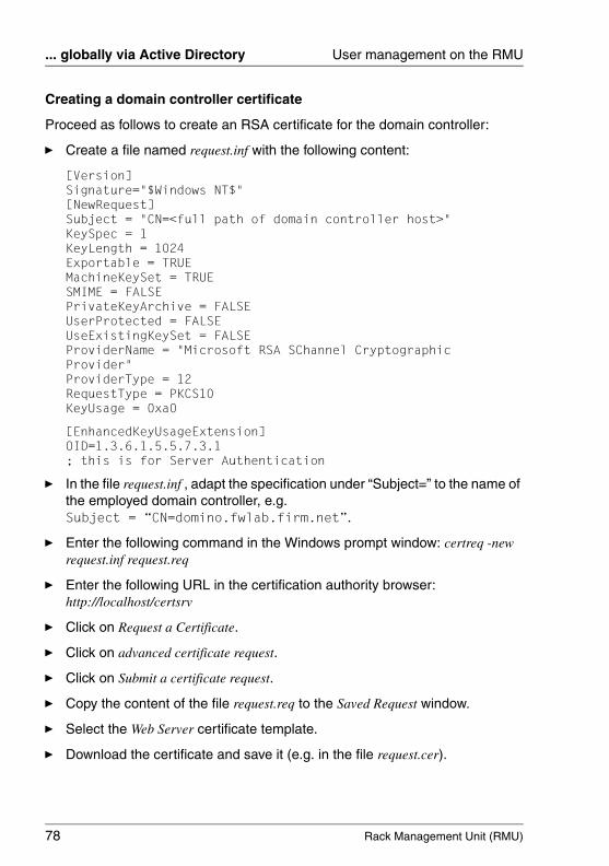
78 Rack Management Unit (RMU)
... globally via Active Directory User management on the RMU
© c
ogni
tas.
Ges
ells
chft
für
Tech
nik-
Dok
umen
tatio
n m
bH 2
009
Pfa
d: A
:\Ben
_Nev
is_R
MU
\Han
dbuc
h\en
\rm
u-en
.k04
Creating a domain controller certificate
Proceed as follows to create an RSA certificate for the domain controller:
Ê Create a file named request.inf with the following content:
[Version]Signature="$Windows NT$"[NewRequest]Subject = "CN=<full path of domain controller host>"KeySpec = 1KeyLength = 1024Exportable = TRUEMachineKeySet = TRUESMIME = FALSEPrivateKeyArchive = FALSEUserProtected = FALSEUseExistingKeySet = FALSEProviderName = "Microsoft RSA SChannel Cryptographic Provider"ProviderType = 12RequestType = PKCS10KeyUsage = 0xa0
[EnhancedKeyUsageExtension]OID=1.3.6.1.5.5.7.3.1; this is for Server Authentication
Ê In the file request.inf , adapt the specification under “Subject=” to the name of the employed domain controller, e.g. Subject = “CN=domino.fwlab.firm.net”.
Ê Enter the following command in the Windows prompt window: certreq -new request.inf request.req
Ê Enter the following URL in the certification authority browser: http://localhost/certsrv
Ê Click on Request a Certificate.
Ê Click on advanced certificate request.
Ê Click on Submit a certificate request.
Ê Copy the content of the file request.req to the Saved Request window.
Ê Select the Web Server certificate template.
Ê Download the certificate and save it (e.g. in the file request.cer).
Rack Management Unit (RMU) 79
User management on the RMU ... globally via Active Directory
Ê Enter the following command in the Windows prompt window: certreq -accept request.cer
Ê Export the certificate with the private key.
To do this, proceed as follows:
Ê Enter mmc in the Windows prompt window to start the Management Console.
Ê Add the snap-in for local computer certificates.
Ê Navigate to Certificates (Local Computer) - Personal Certificates - Certificates.
Ê Double-click on the new server certification authentication certificate.
Ê Click on the Details tab in the certificate window.
Ê Click on Copy to File.
Ê Select Yes, export the private key.
Ê Assign a password.
Ê Choose a file name for the certificate and click on Finish.
80 Rack Management Unit (RMU)
... globally via Active Directory User management on the RMU
© c
ogni
tas.
Ges
ells
chft
für
Tech
nik-
Dok
umen
tatio
n m
bH 2
009
Pfa
d: A
:\Ben
_Nev
is_R
MU
\Han
dbuc
h\en
\rm
u-en
.k04
Installing the domain controller certificate on the server
Proceed as follows to install the domain controller certificate on the server:
Ê Copy the domain controller certificate file that has just been created to the domain controller.
Ê Double-click on the domain controller certificate.
Ê Click on Install Certificate.
Ê Use the password which you assigned when exporting the certificate.
Ê Under Place all certificates in the following store click on Browse and choose Personal Certificates.
Ê Enter mmc in the Windows prompt window to start the Management Console.
Ê Add the snap-in for local computer certificates.
Ê Add the snap-in for the current user’s certificates.
Ê Copy the domain controller certificate from the current user’s Personal Certificates directory to the local computer's Personal Certificates directory.
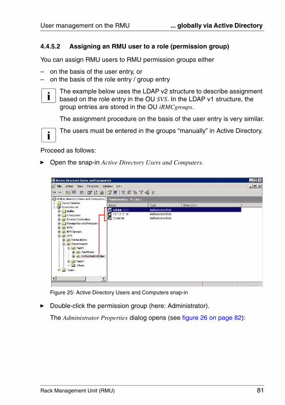
Rack Management Unit (RMU) 81
User management on the RMU ... globally via Active Directory
4.4.5.2 Assigning an RMU user to a role (permission group)
You can assign RMU users to RMU permission groups either
– on the basis of the user entry, or– on the basis of the role entry / group entry
I The example below uses the LDAP v2 structure to describe assignment based on the role entry in the OU SVS. In the LDAP v1 structure, the group entries are stored in the OU iRMCgroups.
The assignment procedure on the basis of the user entry is very similar.
I The users must be entered in the groups “manually” in Active Directory.
Proceed as follows:
Ê Open the snap-in Active Directory Users and Computers.
Figure 25: Active Directory Users and Computers snap-in
Ê Double-click the permission group (here: Administrator).
The Administrator Properties dialog opens (see figure 26 on page 82):

82 Rack Management Unit (RMU)
... globally via Active Directory User management on the RMU
© c
ogni
tas.
Ges
ells
chft
für
Tech
nik-
Dok
umen
tatio
n m
bH 2
009
Pfa
d: A
:\Ben
_Nev
is_R
MU
\Han
dbuc
h\en
\rm
u-en
.k04
Figure 26: Administrator Properties dialog
Ê Select the Members tab.
Ê Click on the Add... button.
The Select Users, Contacts, or Computers dialog opens (see figure 27 on page 83).
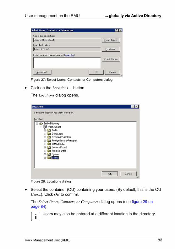
Rack Management Unit (RMU) 83
User management on the RMU ... globally via Active Directory
Figure 27: Select Users, Contacts, or Computers dialog
Ê Click on the Locations... button.
The Locations dialog opens.
Figure 28: Locations dialog
Ê Select the container (OU) containing your users. (By default, this is the OU Users.). Click OK to confirm.
The Select Users, Contacts, or Computers dialog opens (see figure 29 on page 84).
I Users may also be entered at a different location in the directory.
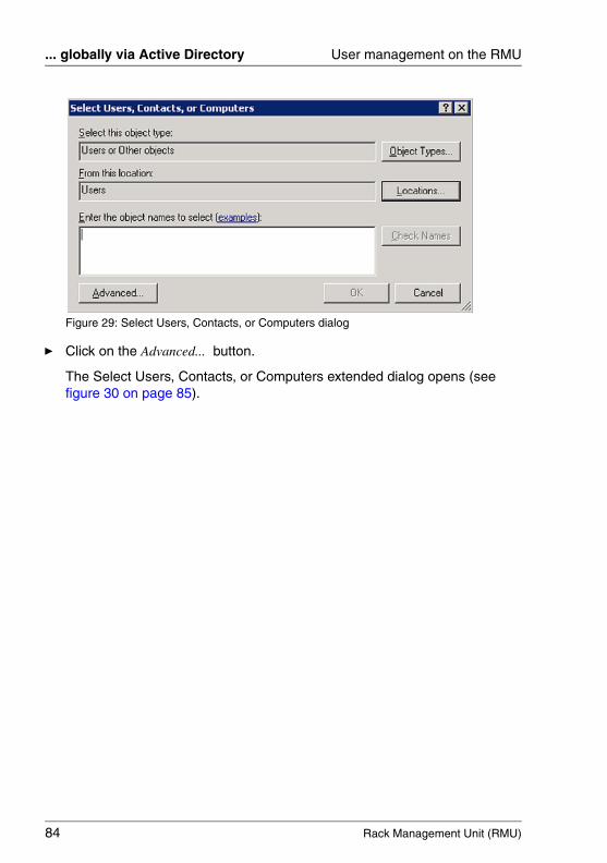
84 Rack Management Unit (RMU)
... globally via Active Directory User management on the RMU
© c
ogni
tas.
Ges
ells
chft
für
Tech
nik-
Dok
umen
tatio
n m
bH 2
009
Pfa
d: A
:\Ben
_Nev
is_R
MU
\Han
dbuc
h\en
\rm
u-en
.k04
Figure 29: Select Users, Contacts, or Computers dialog
Ê Click on the Advanced... button.
The Select Users, Contacts, or Computers extended dialog opens (see figure 30 on page 85).
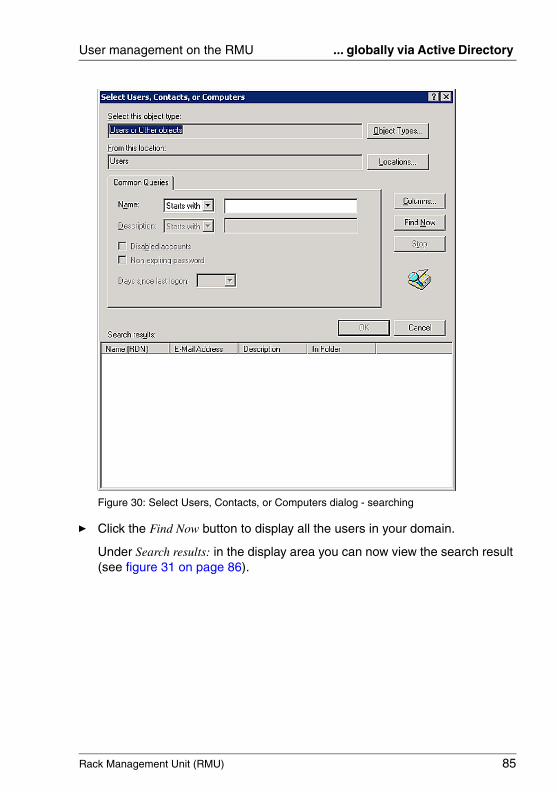
Rack Management Unit (RMU) 85
User management on the RMU ... globally via Active Directory
Figure 30: Select Users, Contacts, or Computers dialog - searching
Ê Click the Find Now button to display all the users in your domain.
Under Search results: in the display area you can now view the search result (see figure 31 on page 86).

86 Rack Management Unit (RMU)
... globally via Active Directory User management on the RMU
© c
ogni
tas.
Ges
ells
chft
für
Tech
nik-
Dok
umen
tatio
n m
bH 2
009
Pfa
d: A
:\Ben
_Nev
is_R
MU
\Han
dbuc
h\en
\rm
u-en
.k04
Figure 31: Select Users, Contacts, or Computers dialog - displaying the search results
Ê Select the users who are to be added to the group and click OK to confirm.
The selected users are now displayed (see figure 32 on page 87).
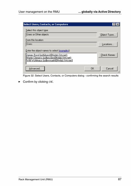
Rack Management Unit (RMU) 87
User management on the RMU ... globally via Active Directory
Figure 32: Select Users, Contacts, or Computers dialog - confirming the search results
Ê Confirm by clicking OK.

88 Rack Management Unit (RMU)
... globally via Novell eDirectory User management on the RMU
© c
ogni
tas.
Ges
ells
chft
für
Tech
nik-
Dok
umen
tatio
n m
bH 2
009
Pfa
d: A
:\Ben
_Nev
is_R
MU
\Han
dbuc
h\en
\rm
u-en
.k04
4.4.6 RMU user management via Novell eDirectory
This section provides you with information about the following topics:
– The Novell eDirectory system components and system requirements
– Installing Novell eDirectory
– Configuring Novell eDirectory
– Integrating RMUuser management in Novell eDirectory
– Tips on administering Novell eDirectory.
I The installation and configuration of Novell eDirectory are described in detail below. No extensive eDirectory knowledge is required. If you are already familiar with Novell eDirectory, you can skip the next three sections and continue with section "Integrating RMU user management in Novell eDirectory" on page 102.
4.4.6.1 Software components and system requirements
I Use the specified version or a more recent version of the components listed below.
Novell eDirectory (formerly NDS) consists of the following software compo-nents:
– eDirectory 8.8: 20060526_0800_Linux_88-SP1_FINAL.tar.gz
– eDirectory 8.8: eDir_88_iMan26_Plugins.npm
– iManager: iMan_26_linux_64.tgz for SuSE, iMan_26_linux_32.tgz otherwise
– ConsoleOne: c1_136f-linux.tar.gz
The following system requirements must be fulfilled in order to install and operate Novell eDirectory:
– OpenSSL must be installed.
I If OpenSSL is not already installed:
Ê Install OpenSSL, before starting the Novell eDirectory instal-lation.
– 512 MB free RAM
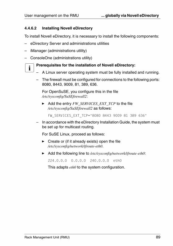
Rack Management Unit (RMU) 89
User management on the RMU ... globally via Novell eDirectory
4.4.6.2 Installing Novell eDirectory
To install Novell eDirectory, it is necessary to install the following components:
– eDirectory Server and administrations utilities
– iManager (administrations utility)
– ConsoleOne (administrations utility)
I Prerequisites for the installation of Novell eDirectory:
– A Linux server operating system must be fully installed and running.
– The firewall must be configured for connections to the following ports: 8080, 8443, 9009, 81, 389, 636.
For OpenSuSE, you configure this in the file /etc/sysconfig/SuSEfirewall2:
Ê Add the entry FW_SERVICES_EXT_TCP to the file /etc/sysconfig/SuSEfirewall2 as follows:
FW_SERVICES_EXT_TCP="8080 8443 9009 81 389 636"
– In accordance with the eDirectory Installation Guide, the system must be set up for multicast routing.
For SuSE Linux, proceed as follows:
Ê Create or (if it already exists) open the file /etc/sysconfig/network/ifroute-eth0.
Ê Add the following line to /etc/sysconfig/network/ifroute-eth0:
224.0.0.0 0.0.0.0 240.0.0.0 eth0
This adapts eth0 to the system configuration.
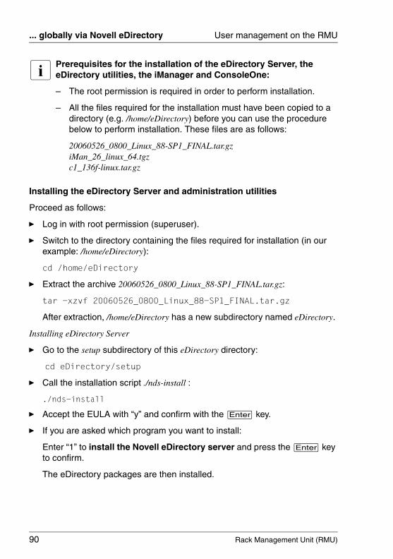
90 Rack Management Unit (RMU)
... globally via Novell eDirectory User management on the RMU
© c
ogni
tas.
Ges
ells
chft
für
Tech
nik-
Dok
umen
tatio
n m
bH 2
009
Pfa
d: A
:\Ben
_Nev
is_R
MU
\Han
dbuc
h\en
\rm
u-en
.k04
I Prerequisites for the installation of the eDirectory Server, the eDirectory utilities, the iManager and ConsoleOne:
– The root permission is required in order to perform installation.
– All the files required for the installation must have been copied to a directory (e.g. /home/eDirectory) before you can use the procedure below to perform installation. These files are as follows:
20060526_0800_Linux_88-SP1_FINAL.tar.gz iMan_26_linux_64.tgzc1_136f-linux.tar.gz
Installing the eDirectory Server and administration utilities
Proceed as follows:
Ê Log in with root permission (superuser).
Ê Switch to the directory containing the files required for installation (in our example: /home/eDirectory):
cd /home/eDirectory
Ê Extract the archive 20060526_0800_Linux_88-SP1_FINAL.tar.gz:
tar -xzvf 20060526_0800_Linux_88-SP1_FINAL.tar.gz
After extraction, /home/eDirectory has a new subdirectory named eDirectory.
Installing eDirectory Server
Ê Go to the setup subdirectory of this eDirectory directory:
cd eDirectory/setup
Ê Call the installation script ./nds-install :
./nds-install
Ê Accept the EULA with “y” and confirm with the [Enter] key.
Ê If you are asked which program you want to install:
Enter “1” to install the Novell eDirectory server and press the [Enter] key to confirm.
The eDirectory packages are then installed.

Rack Management Unit (RMU) 91
User management on the RMU ... globally via Novell eDirectory
After installation of the Novell eDirectory Server, you must update the names for the paths to the eDirectory in a number of environment variables and export these variables.
Ê To do this, open your configuration file (in the example: /etc/bash.bashrc) and enter the following lines in the specified sequence ahead of “# End of ...”:
export PATH/opt/novell/eDirectory/bin:/opt/novell/eDirectory/sbin:$PATH
export LD_LIBRARY_PATH=/opt/novell/eDirectory/lib:/opt/novell/eDirectory/lib/nds-modules:/opt/novell/lib:$LD_LIBRARY_PATH
export MANPATH=/opt/novell/man:/opt/novell/eDirectory/man:$MANPATH
export TEXTDOMAINDIR=/opt/novell/eDirectory/share/locale:$TEXTDOMAINDIR
Ê Close the terminal and open a new terminal in order to export the environment variables.
Installing the eDirectory administration utilities
Ê Go to the setup subdirectory of the eDirectory directory:
cd eDirectory/setup
Ê Call the installation script:
./nds-install
Ê Accept the EULA with “y” and confirm with the [Enter] key.
Ê If you are asked which program you want to install:
Enter “2” to install the Novell eDirectory administration utilities and press the [Enter] key to confirm.
The eDirectory administration utilities are then installed.
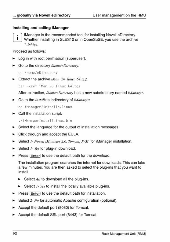
92 Rack Management Unit (RMU)
... globally via Novell eDirectory User management on the RMU
© c
ogni
tas.
Ges
ells
chft
für
Tech
nik-
Dok
umen
tatio
n m
bH 2
009
Pfa
d: A
:\Ben
_Nev
is_R
MU
\Han
dbuc
h\en
\rm
u-en
.k04
Installing and calling iManager
I iManager is the recommended tool for installing Novell eDirectory. Whether installing in SLES10 or in OpenSuSE, you use the archive *_64.tgz.
Proceed as follows:
Ê Log in with root permission (superuser).
Ê Go to the directory /home/eDirectory:
cd /home/eDirectory
Ê Extract the archive iMan_26_linux_64.tgz:
tar -xzvf iMan_26_linux_64.tgz
After extraction, /home/eDirectory has a new subdirectory named iManager.
Ê Go to the installs subdirectory of iManager:
cd iManager/installs/linux
Ê Call the installation script:
./iManagerInstallLinux.bin
Ê Select the language for the output of installation messages.
Ê Click through and accept the EULA.
Ê Select 1- Novell iManager 2.6, Tomcat, JVM for iManager installation.
Ê Select 1- Yes for plug-in download.
Ê Press [Enter] to use the default path for the download.
The installation program searches the internet for downloads. This can take a few minutes. You are then asked to select the plug-ins that you want to install.
Ê Select All to download all the plug-ins.
Ê Select 1- Yes to install the locally available plug-ins.
Ê Press [Enter] to use the default path for installation.
Ê Select 2- No for automatic Apache configuration (optional).
Ê Accept the default port (8080) for Tomcat.
Ê Accept the default SSL port (8443) for Tomcat.
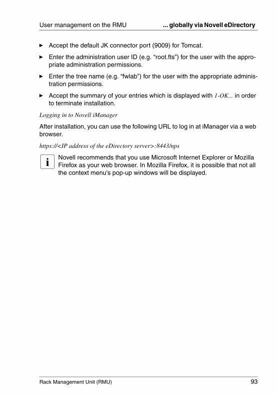
Rack Management Unit (RMU) 93
User management on the RMU ... globally via Novell eDirectory
Ê Accept the default JK connector port (9009) for Tomcat.
Ê Enter the administration user ID (e.g. “root.fts”) for the user with the appro-priate administration permissions.
Ê Enter the tree name (e.g. “fwlab”) for the user with the appropriate adminis-tration permissions.
Ê Accept the summary of your entries which is displayed with 1-OK... in order to terminate installation.
Logging in to Novell iManager
After installation, you can use the following URL to log in at iManager via a web browser.
https://<IP address of the eDirectory server>:8443/nps
I Novell recommends that you use Microsoft Internet Explorer or Mozilla Firefox as your web browser. In Mozilla Firefox, it is possible that not all the context menu's pop-up windows will be displayed.

94 Rack Management Unit (RMU)
... globally via Novell eDirectory User management on the RMU
© c
ogni
tas.
Ges
ells
chft
für
Tech
nik-
Dok
umen
tatio
n m
bH 2
009
Pfa
d: A
:\Ben
_Nev
is_R
MU
\Han
dbuc
h\en
\rm
u-en
.k04
Installing and starting ConsoleOne
ConsoleOne is another administration tool for Novell eDirectory.
Proceed as follows to install ConsoleOne:
Ê Log in with root permission (superuser) at eDirectory Server.
Ê Go to the directory /home/eDirectory:
cd /home/eDirectory
Ê Extract the ConsoleOne archive c1_136f-linux.tar.gz:
tar -xzvf c1_136f-linux.tar.gz
After extraction, /home/eDirectory has a new subdirectory named Linux.
Ê Go to the directory Linux:
cd Linux
Ê Call the installation script c1-install:
./c1-install
Ê Select the language for the output of installation messages.
Ê Enter “8” to install all the snap-ins.
ConsoleOne needs the path to an installed Java runtime environment. You can export the corresponding path name to the environment variable C1_JRE_HOME. However, the system-wide export of the path name requires modifications in the bash profile.
I Since root permission is required in order to work with ConsoleOne, it is, in principle, sufficient to export the ID superuser Root. However, the system-wide export of the path name is presented below. This means that normal users can also work with ConsoleOne if they have root permission.
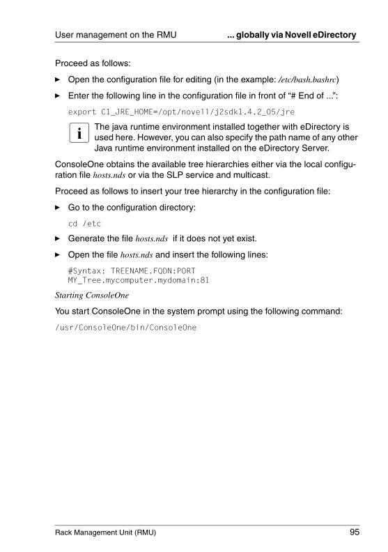
Rack Management Unit (RMU) 95
User management on the RMU ... globally via Novell eDirectory
Proceed as follows:
Ê Open the configuration file for editing (in the example: /etc/bash.bashrc)
Ê Enter the following line in the configuration file in front of “# End of ...”:
export C1_JRE_HOME=/opt/novell/j2sdk1.4.2_05/jre
I The java runtime environment installed together with eDirectory is used here. However, you can also specify the path name of any other Java runtime environment installed on the eDirectory Server.
ConsoleOne obtains the available tree hierarchies either via the local configu-ration file hosts.nds or via the SLP service and multicast.
Proceed as follows to insert your tree hierarchy in the configuration file:
Ê Go to the configuration directory:
cd /etc
Ê Generate the file hosts.nds if it does not yet exist.
Ê Open the file hosts.nds and insert the following lines:
#Syntax: TREENAME.FQDN:PORTMY_Tree.mycomputer.mydomain:81
Starting ConsoleOne
You start ConsoleOne in the system prompt using the following command:
/usr/ConsoleOne/bin/ConsoleOne
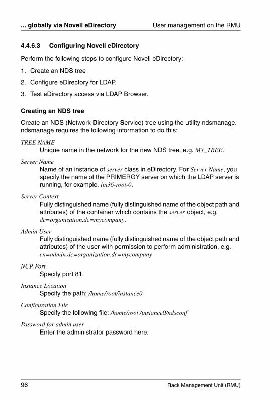
96 Rack Management Unit (RMU)
... globally via Novell eDirectory User management on the RMU
© c
ogni
tas.
Ges
ells
chft
für
Tech
nik-
Dok
umen
tatio
n m
bH 2
009
Pfa
d: A
:\Ben
_Nev
is_R
MU
\Han
dbuc
h\en
\rm
u-en
.k04
4.4.6.3 Configuring Novell eDirectory
Perform the following steps to configure Novell eDirectory:
1. Create an NDS tree
2. Configure eDirectory for LDAP.
3. Test eDirectory access via LDAP Browser.
Creating an NDS tree
Create an NDS (Network Directory Service) tree using the utility ndsmanage. ndsmanage requires the following information to do this:
TREE NAMEUnique name in the network for the new NDS tree, e.g. MY_TREE.
Server NameName of an instance of server class in eDirectory. For Server Name, you specify the name of the PRIMERGY server on which the LDAP server is running, for example. lin36-root-0.
Server ContextFully distinguished name (fully distinguished name of the object path and attributes) of the container which contains the server object, e.g. dc=organization.dc=mycompany.
Admin UserFully distinguished name (fully distinguished name of the object path and attributes) of the user with permission to perform administration, e.g. cn=admin.dc=organization.dc=mycompany
NCP PortSpecify port 81.
Instance LocationSpecify the path: /home/root/instance0
Configuration FileSpecify the following file: /home/root /instance0/ndsconf
Password for admin user Enter the administrator password here.

Rack Management Unit (RMU) 97
User management on the RMU ... globally via Novell eDirectory
Proceed as follows to configure the NDS tree:
Ê Open a command box.
Ê Go to the directory /home/eDirectory.
Ê Start the utility ndsmanage by entering the command ndsmanage:
ndsmanage
Ê Enter “c” to generate a new instance of the class server.
Ê Enter “y” to continue configuration.
Ê Enter “y” to create a new tree.
ndsmanage then queries the values for TREE NAME, Server Name, Server Context etc. in sequence (see page 96).
Once input is complete, ndsmanage configures the NDS tree.
Ê After configuring the NDS tree, restart the PRIMERGY server in order to activate the configuration, i.e. to recreate the NDS tree.
Configuring eDirectory for LDAP
The following steps are involved in configuring eDirectory for LDAP:
– Install Role Based Services (RBS)
– Install plug-in modules
– Configure Role Based Services (RBS)
– Configure eDirectory with/without SSL/TLS support
Proceed as follows to complete the individual points:
Ê Log in under the administrator ID (Admin) at iManager via a web browser.
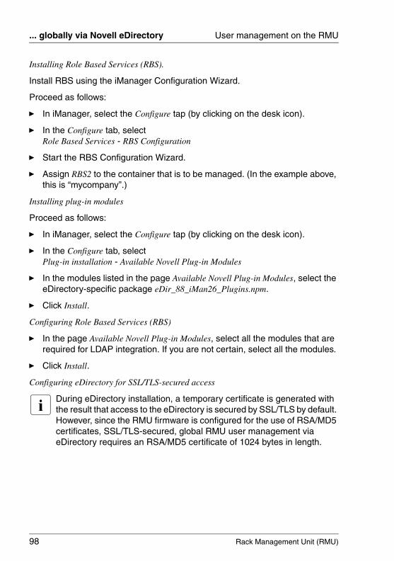
98 Rack Management Unit (RMU)
... globally via Novell eDirectory User management on the RMU
© c
ogni
tas.
Ges
ells
chft
für
Tech
nik-
Dok
umen
tatio
n m
bH 2
009
Pfa
d: A
:\Ben
_Nev
is_R
MU
\Han
dbuc
h\en
\rm
u-en
.k04
Installing Role Based Services (RBS).
Install RBS using the iManager Configuration Wizard.
Proceed as follows:
Ê In iManager, select the Configure tap (by clicking on the desk icon).
Ê In the Configure tab, select Role Based Services - RBS Configuration
Ê Start the RBS Configuration Wizard.
Ê Assign RBS2 to the container that is to be managed. (In the example above, this is “mycompany”.)
Installing plug-in modules
Proceed as follows:
Ê In iManager, select the Configure tap (by clicking on the desk icon).
Ê In the Configure tab, select Plug-in installation - Available Novell Plug-in Modules
Ê In the modules listed in the page Available Novell Plug-in Modules, select the eDirectory-specific package eDir_88_iMan26_Plugins.npm.
Ê Click Install.
Configuring Role Based Services (RBS)
Ê In the page Available Novell Plug-in Modules, select all the modules that are required for LDAP integration. If you are not certain, select all the modules.
Ê Click Install.
Configuring eDirectory for SSL/TLS-secured access
I During eDirectory installation, a temporary certificate is generated with the result that access to the eDirectory is secured by SSL/TLS by default. However, since the RMU firmware is configured for the use of RSA/MD5 certificates, SSL/TLS-secured, global RMU user management via eDirectory requires an RSA/MD5 certificate of 1024 bytes in length.
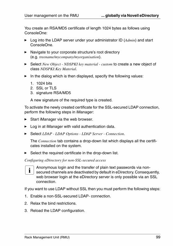
Rack Management Unit (RMU) 99
User management on the RMU ... globally via Novell eDirectory
You create an RSA/MD5 certificate of length 1024 bytes as follows using ConsoleOne:
Ê Log into the LDAP server under your administrator ID (Admin) and start ConsoleOne.
Ê Navigate to your corporate structure's root directory (e.g. treename/mycompany/myorganisation).
Ê Select New Object - NDSPKI key material - custom to create a new object of class NDSPKI:Key Material.
Ê In the dialog which is then displayed, specify the following values:
1. 1024 bits 2. SSL or TLS 3. signature RSA/MD5
A new signature of the required type is created.
To activate the newly created certificate for the SSL-secured LDAP connection, perform the following steps in iManager:
Ê Start iManager via the web browser.
Ê Log in at iManager with valid authentication data.
Ê Select LDAP - LDAP Options - LDAP Server - Connection.
The Connection tab contains a drop-down list which displays all the certifi-cates installed on the system.
Ê Select the required certificate in the drop-down list.
Configuring eDirectory for non-SSL-secured access
I Anonymous login and the transfer of plain text passwords via non-secured channels are deactivated by default in eDirectory. Consequently, web browser login at the eDirectory server is only possible via an SSL connection.
If you want to use LDAP without SSL then you must perform the following steps:
1. Enable a non-SSL-secured LDAP- connection.
2. Relax the bind restrictions.
3. Reload the LDAP configuration.
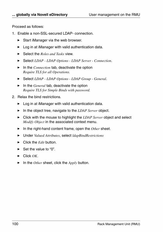
100 Rack Management Unit (RMU)
... globally via Novell eDirectory User management on the RMU
© c
ogni
tas.
Ges
ells
chft
für
Tech
nik-
Dok
umen
tatio
n m
bH 2
009
Pfa
d: A
:\Ben
_Nev
is_R
MU
\Han
dbuc
h\en
\rm
u-en
.k04
Proceed as follows:
1. Enable a non-SSL-secured LDAP- connection.
Ê Start iManager via the web browser.
Ê Log in at iManager with valid authentication data.
Ê Select the Roles and Tasks view.
Ê Select LDAP - LDAP Options - LDAP Server - Connection.
Ê In the Connection tab, deactivate the option Require TLS for all Operations.
Ê Select LDAP - LDAP Options - LDAP Group - General.
Ê In the General tab, deactivate the option Require TLS for Simple Binds with password.
2. Relax the bind restrictions.
Ê Log in at iManager with valid authentication data.
Ê In the object tree, navigate to the LDAP Server object.
Ê Click with the mouse to highlight the LDAP Server object and select Modify Object in the associated context menu.
Ê In the right-hand content frame, open the Other sheet.
Ê Under Valued Attributes, select ldapBindRestrictions
Ê Click the Edit button.
Ê Set the value to “0”.
Ê Click OK.
Ê In the Other sheet, click the Apply button.
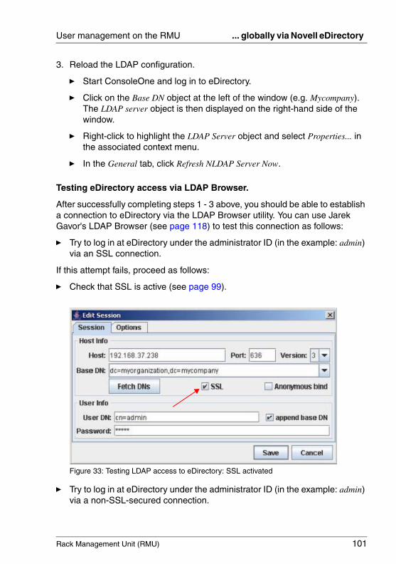
Rack Management Unit (RMU) 101
User management on the RMU ... globally via Novell eDirectory
3. Reload the LDAP configuration.
Ê Start ConsoleOne and log in to eDirectory.
Ê Click on the Base DN object at the left of the window (e.g. Mycompany). The LDAP server object is then displayed on the right-hand side of the window.
Ê Right-click to highlight the LDAP Server object and select Properties... in the associated context menu.
Ê In the General tab, click Refresh NLDAP Server Now.
Testing eDirectory access via LDAP Browser.
After successfully completing steps 1 - 3 above, you should be able to establish a connection to eDirectory via the LDAP Browser utility. You can use Jarek Gavor's LDAP Browser (see page 118) to test this connection as follows:
Ê Try to log in at eDirectory under the administrator ID (in the example: admin) via an SSL connection.
If this attempt fails, proceed as follows:
Ê Check that SSL is active (see page 99).
Figure 33: Testing LDAP access to eDirectory: SSL activated
Ê Try to log in at eDirectory under the administrator ID (in the example: admin) via a non-SSL-secured connection.
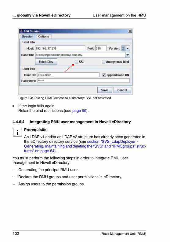
102 Rack Management Unit (RMU)
... globally via Novell eDirectory User management on the RMU
© c
ogni
tas.
Ges
ells
chft
für
Tech
nik-
Dok
umen
tatio
n m
bH 2
009
Pfa
d: A
:\Ben
_Nev
is_R
MU
\Han
dbuc
h\en
\rm
u-en
.k04
Figure 34: Testing LDAP access to eDirectory: SSL not activated
Ê If the login fails again:Relax the bind restrictions (see page 99).
4.4.6.4 Integrating RMU user management in Novell eDirectory
I Prerequisite:
An LDAP v1 and/or an LDAP v2 structure has already been generated in the eDirectory directory service (see section "SVS_LdapDeployer - Generating, maintaining and deleting the “SVS” and “iRMCgroups” struc-tures" on page 64).
You must perform the following steps in order to integrate RMU user management in Novell eDirectory:
– Generating the principal RMU user.
– Declare the RMU groups and user permissions in eDirectory.
– Assign users to the permission groups.
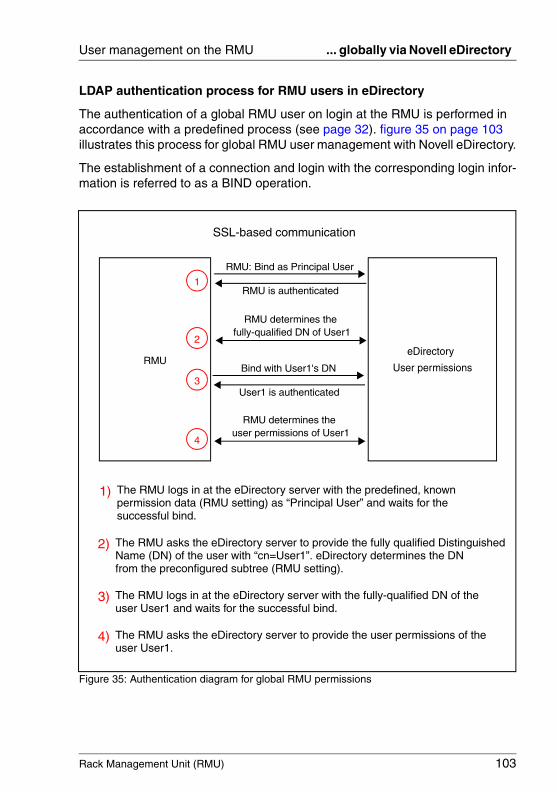
Rack Management Unit (RMU) 103
User management on the RMU ... globally via Novell eDirectory
LDAP authentication process for RMU users in eDirectory
The authentication of a global RMU user on login at the RMU is performed in accordance with a predefined process (see page 32). figure 35 on page 103 illustrates this process for global RMU user management with Novell eDirectory.
The establishment of a connection and login with the corresponding login infor-mation is referred to as a BIND operation.
Figure 35: Authentication diagram for global RMU permissions
RMUeDirectory
User permissions
RMU: Bind as Principal User
RMU is authenticated
RMU determines the fully-qualified DN of User1
Bind with User1's DN
User1 is authenticated
RMU determines the user permissions of User1
1
2
3
4
1) The RMU logs in at the eDirectory server with the predefined, known permission data (RMU setting) as “Principal User” and waits for the
2) The RMU asks the eDirectory server to provide the fully qualified Distinguished Name (DN) of the user with “cn=User1”. eDirectory determines the DN
4) The RMU asks the eDirectory server to provide the user permissions of the
from the preconfigured subtree (RMU setting).
successful bind.
3) The RMU logs in at the eDirectory server with the fully-qualified DN of the user User1 and waits for the successful bind.
user User1.
SSL-based communication
104 Rack Management Unit (RMU)
... globally via Novell eDirectory User management on the RMU
© c
ogni
tas.
Ges
ells
chft
für
Tech
nik-
Dok
umen
tatio
n m
bH 2
009
Pfa
d: A
:\Ben
_Nev
is_R
MU
\Han
dbuc
h\en
\rm
u-en
.k04
I You configure the “Principal User's” permission data and the subtree which contains the DNs in the page Directory Service Configuration page of the RMU web interface (see page 211).
I A user's CN must be unique within the searched subtree.
Creating the Principal User for the RMU
Proceed as follows to create the Principal User for the RMU:
Ê Log in at iManager with valid authentication data.
Ê Select Roles and Tasks.
Ê Select Users - Create User.
Ê Enter the necessary specifications in the displayed template.
I The Principal User's Distinguished Name (DN) and password must match the corresponding specifications for the RMU configuration (see section "Directory Service Configuration (LDAP) - Configuring the directory service at the RMU" on page 211).
The user's Context: may be located at any position in the tree.
Ê Assign the Principal User search permissions for the following subtrees:
– Subtree (OU) iRMCgroups or SVS – Subtree (OU) that contains the users (e.g. people).
Assigning user permissions to the RMU groups and users
By default, an object in eDirectory possesses only very limited query and search permissions in an LDAP tree. If an object is to be able to query all the attributes in one or more subtrees, you must assign this object the corresponding permis-sions.
You may assign permissions either to an individual object (i.e. a specific user) or to a group of objects which are collated in the same organizational unit (OU) such as iRMCgroups / SVS or people. In this case, the permissions assigned to an OU and identified as “inherited” are automatically passed on to the objects in this group.
Rack Management Unit (RMU) 105
User management on the RMU ... globally via Novell eDirectory
I To integrate RMU user management in Novell eDirectory, it is necessary to assign search permissions to the following objects (trustees):
– Principal User– Subtree which contains the RMU users
Detailed information on how to do this can be found below.
Proceed as follows to assign an object search permissions for all attributes:
Ê Start iManager via the web browser.
Ê Log in at iManager with valid authentication data.
Ê In iManager, click the Roles and Tasks button.
Ê In the menu tree structure, select Rights - Rights to Other Objects.
The page Rights to Other Objects is displayed.
Ê Under Trustee Name, specify the name of the object (in figure 36 on page 106 iRMCgroups.sbrd4 and SVS.sbdr4) to which the permission is to be granted.
Ê Under Context to Search From, specify the eDirectory subtree (iRMCgroups /
SVS) which iManager is to search through for all the objects for which the trustee Users currently has read permission.
Ê Click OK.
A progress display indicates the status of the search. Once the search operation has been completed, the page Rights to Other Objects is displayed with the results of the search (see figure 36 on page 106).
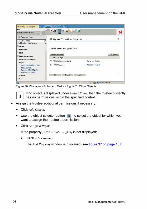
106 Rack Management Unit (RMU)
... globally via Novell eDirectory User management on the RMU
© c
ogni
tas.
Ges
ells
chft
für
Tech
nik-
Dok
umen
tatio
n m
bH 2
009
Pfa
d: A
:\Ben
_Nev
is_R
MU
\Han
dbuc
h\en
\rm
u-en
.k04
Figure 36: iManager - Roles and Tasks - Rights To Other Objects
I If no object is displayed under Object Name, then the trustee currently has no permissions within the specified context.
Ê Assign the trustee additional permissions if necessary:
Ê Click Add Object.
Ê Use the object selector button to select the object for which you want to assign the trustee a permission.
Ê Click Assigned Rights.
If the property [All Attributes Rights] is not displayed:
Ê Click Add Property.
The Add Property window is displayed (see figure 37 on page 107).
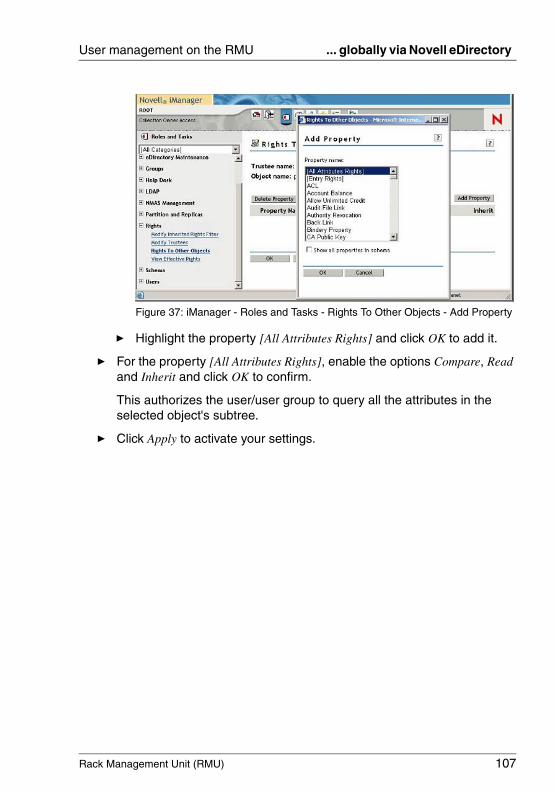
Rack Management Unit (RMU) 107
User management on the RMU ... globally via Novell eDirectory
Figure 37: iManager - Roles and Tasks - Rights To Other Objects - Add Property
Ê Highlight the property [All Attributes Rights] and click OK to add it.
Ê For the property [All Attributes Rights], enable the options Compare, Read and Inherit and click OK to confirm.
This authorizes the user/user group to query all the attributes in the selected object's subtree.
Ê Click Apply to activate your settings.
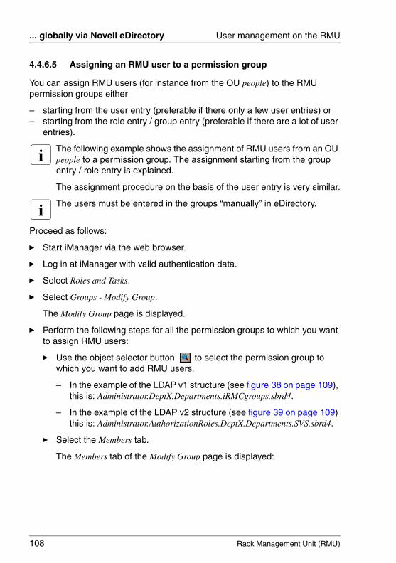
108 Rack Management Unit (RMU)
... globally via Novell eDirectory User management on the RMU
© c
ogni
tas.
Ges
ells
chft
für
Tech
nik-
Dok
umen
tatio
n m
bH 2
009
Pfa
d: A
:\Ben
_Nev
is_R
MU
\Han
dbuc
h\en
\rm
u-en
.k04
4.4.6.5 Assigning an RMU user to a permission group
You can assign RMU users (for instance from the OU people) to the RMU permission groups either
– starting from the user entry (preferable if there only a few user entries) or– starting from the role entry / group entry (preferable if there are a lot of user
entries).
I The following example shows the assignment of RMU users from an OU people to a permission group. The assignment starting from the group entry / role entry is explained.
The assignment procedure on the basis of the user entry is very similar.
I The users must be entered in the groups “manually” in eDirectory.
Proceed as follows:
Ê Start iManager via the web browser.
Ê Log in at iManager with valid authentication data.
Ê Select Roles and Tasks.
Ê Select Groups - Modify Group.
The Modify Group page is displayed.
Ê Perform the following steps for all the permission groups to which you want to assign RMU users:
Ê Use the object selector button to select the permission group to which you want to add RMU users.
– In the example of the LDAP v1 structure (see figure 38 on page 109), this is: Administrator.DeptX.Departments.iRMCgroups.sbrd4.
– In the example of the LDAP v2 structure (see figure 39 on page 109) this is: Administrator.AuthorizationRoles.DeptX.Departments.SVS.sbrd4.
Ê Select the Members tab.
The Members tab of the Modify Group page is displayed:

Rack Management Unit (RMU) 109
User management on the RMU ... globally via Novell eDirectory
Figure 38: iManager - Roles and Tasks - Modify Group - “Members” tab(LDAP v1)
Figure 39: iManager - Roles and Tasks - Modify Group - “Members” tab (LDAP v2)
Ê Perform the following steps for all the users of the OU people which you want to assign to the RMU group:
Ê Click the object selector button .
The Object Selector (Browser) window is opened (see figure 40 on page 110).
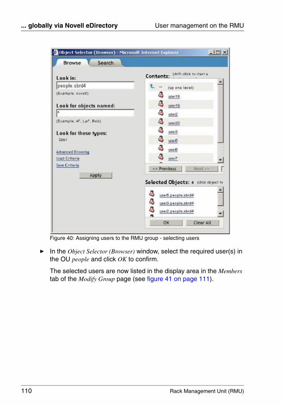
110 Rack Management Unit (RMU)
... globally via Novell eDirectory User management on the RMU
© c
ogni
tas.
Ges
ells
chft
für
Tech
nik-
Dok
umen
tatio
n m
bH 2
009
Pfa
d: A
:\Ben
_Nev
is_R
MU
\Han
dbuc
h\en
\rm
u-en
.k04
Figure 40: Assigning users to the RMU group - selecting users
Ê In the Object Selector (Browser) window, select the required user(s) in the OU people and click OK to confirm.
The selected users are now listed in the display area in the Members tab of the Modify Group page (see figure 41 on page 111).
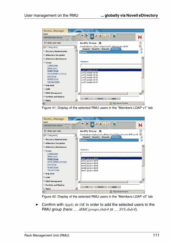
Rack Management Unit (RMU) 111
User management on the RMU ... globally via Novell eDirectory
Figure 41: Display of the selected RMU users in the “Members LDAP v1” tab
Figure 42: Display of the selected RMU users in the “Members LDAP v2” tab
Ê Confirm with Apply or OK in order to add the selected users to the RMU group (here: ... .iRMCgroups.sbdr4 or ... .SVS.sbdr4).
112 Rack Management Unit (RMU)
... globally via Novell eDirectory User management on the RMU
© c
ogni
tas.
Ges
ells
chft
für
Tech
nik-
Dok
umen
tatio
n m
bH 2
009
Pfa
d: A
:\Ben
_Nev
is_R
MU
\Han
dbuc
h\en
\rm
u-en
.k04
4.4.6.6 Tips on administering Novell eDirectory.
Restarting the NDS daemon
Proceed as follows to restart the NDS daemon:
Ê Open the command box.
Ê Log in with root permission.
Ê Execute the following command:
rcndsd restart
If, for any unidentifiable reason, the nldap daemon fails to start:
Ê Start the lndap daemon “manually”:
/etc/init.d/nldap restart
If iManager does not respond:
Ê Restart iManager:
/etc/init.d/novell-tomcat4 restart
Reloading the configuration of the NLDAP server
Proceed as follows:
Ê Start ConsoleOne and log in to eDirectory.
I If you are starting ConsoleOne for the first time, no tree is configured.
Proceed as follows to configure a tree:
Ê Under My World, select the node NDS.
Ê In the menu bar, select: File - Authenticate
Ê Enter the following authentication data for login:
1. Login-Name: root
2. Password: <password>
3. Tree: MY_TREE
4. Context: mycompany

Rack Management Unit (RMU) 113
User management on the RMU ... globally via Novell eDirectory
Ê In the left-hand part of the window, click the Base DN object (Mycompany).
The LDAP Server object is then displayed in the right-hand side of the window.
Ê Right-click on the LDAP Server object and select Properties... in the context menu.
Ê In the General tab, click the Refresh NLDAP Server Now button.
Configuring the NDS message trace
The nds daemon generates debug and log messages which you can trace using the ndstrace tool. The purpose of the configuration described below is to redirect the output from ndstrace to a file and display the content of this file at another terminal. For this latter task, you use the screen tool.
The following procedure is recommended:
Ê Open the command box (e.g. bash).
Configuring ndstrace
Ê Go to the eDirectory directory /home/eDirectory:
cd /home/eDirectory
Ê Start screen by means of the command screen.
Ê Start ndstrace with the command ndstrace.
Ê Select the modules that you want to activate.
For example, if you want to display the times at which events occurred, enter dstrace TIME.
I You are very strongly recommended to activate the modules LDAP and TIME by making the following entry:
dstrace LDAP TIME
Ê Terminate ndstrace by entering quit.
This terminates the configuration of ndstrace.
114 Rack Management Unit (RMU)
... globally via Novell eDirectory User management on the RMU
© c
ogni
tas.
Ges
ells
chft
für
Tech
nik-
Dok
umen
tatio
n m
bH 2
009
Pfa
d: A
:\Ben
_Nev
is_R
MU
\Han
dbuc
h\en
\rm
u-en
.k04
Outputting messages at a second terminal
Ê Start ndstrace and redirect message output:
ndstrace -l >ndstrace.log
Ê Use the following key combination to open a second terminal: [Ctrl] + [a], [Ctrl] + [c]
Ê Activate log recording:
tail -f ./ndstrace.log
Ê To switch between the virtual terminals, use the key combination [Ctrl] + [a], [Ctrl] + [0]. (The terminals are numbered from 0 to 9)
Rack Management Unit (RMU) 115
User management on the RMU ... globally via OpenLDAP
4.4.7 RMU user management via OpenLDAP
This section provides you with information about the following topics:
– Installing OpenLDAP (Linux).
– Creating an SSL certificate.
– Configuring OpenLDAP.
– Integrating RMU user management in OpenLDAP.
– Tips on OpenLDAP administration
4.4.7.1 Installing OpenLDAP
I Before installing OpenLDAP, you must configure the firewall for connec-tions to the ports 389 and 636.
For OpenSuSE, proceed as follows:
Ê In the file, /etc/sysconfig/SuSEfirewall2 extend the option FW_SERVICES_EXT_TCP as follows:
FW_SERVICES_EXT_TCP=“389 636”
To install the packages OpenSSL and OpenLDAP2 from the distribution medium, use the setup tool YaST.
4.4.7.2 Creating SSL certificates
You should create a certificate with the following properties:
– Key length: 1024 bits– md5RSAEnc
You use OpenSSL to create key pairs and signed certificates (self-signed or signed by an external CA). For more detailed information, see the OpenSSL home page at http://www.openssl.org.
The following links provide instructions on setting up a CA and creating test certificates:
– http://www.akadia.com/services/ssh_test_certificate.html– http://www.freebsdmadeeasy.com/tutorials/web-server/apache-ssl-certs.php– http://www.flatmtn.com/computer/Linux-SSLCertificates.html – http://www.tc.umn.edu/~brams006/selfsign.html
116 Rack Management Unit (RMU)
... globally via OpenLDAP User management on the RMU
© c
ogni
tas.
Ges
ells
chft
für
Tech
nik-
Dok
umen
tatio
n m
bH 2
009
Pfa
d: A
:\Ben
_Nev
is_R
MU
\Han
dbuc
h\en
\rm
u-en
.k04
Following certificate creation, you must have the following three PEM files:
– Root certificate: root.cer.pem
– Server certificate: server.cer.pem
– Private key: server.key.pem
I The private key must not be encrypted with a pass phrase since you should only assign the LDAP daemon (ldap) read permission for the file server.key.pem.
You use the following command to remove the pass phrase:
openssl rsa -in server.enc.key.pem -out server.key.pem
4.4.7.3 Configuring OpenLDAP
Proceed as follows to configure OpenLDAP:
Ê Start the Yast setup tool and select LDAP-Server-Configuration.
Ê Under Global Settings/Allow Settings, activate the setting LDAPv2-Bind.
Ê Select Global Settings/TLS Settings:
Ê Activate the setting TLS.
Ê Declare the paths of the files created during installation (see section "Installing OpenLDAP" on page 115).
Ê Make sure that certificates and private keys in the file system can be read by the LDAP service.
Since openldap is executed under the uid/guid=ldap, you can do this by
– setting the owner of the files with the certificates and private keys to “ldap”, or
– by assigning the LDAP daemon ldap read permission for the files containing the certificates and private keys.
Rack Management Unit (RMU) 117
User management on the RMU ... globally via OpenLDAP
Ê Select Databases to create a new database.
I If the configuration created by YaST does not function overall, check that the following obligatory entries are present in the file /etc/openldap/slapd.conf:
allow bind_v2
TLSCACertificateFile /path/to/ca-certificate.pem
TLSCertificateFile /path/to/certificate.pem
TLSCertificateKeyFile /path/to/privat.key.pem
I If the configuration created by YaST for SSL does not function, check that the following entry is present in the configuration file /etc/sysconfig/openldap:
OPENLDAP_START_LDAPS=“yes”
118 Rack Management Unit (RMU)
... globally via OpenLDAP User management on the RMU
© c
ogni
tas.
Ges
ells
chft
für
Tech
nik-
Dok
umen
tatio
n m
bH 2
009
Pfa
d: A
:\Ben
_Nev
is_R
MU
\Han
dbuc
h\en
\rm
u-en
.k04
4.4.7.4 Integrating RMU user management in OpenLDAP.
I Prerequisite:
An LDAP v1 and/or an LDAP v2 structure has already been generated in the OpenLDAP directory service (see section "SVS_LdapDeployer - Generating, maintaining and deleting the “SVS” and “iRMCgroups” struc-tures" on page 64).
The integration of RMU user management in OpenLDAP comprises the following steps:
– Generating the principal RMU user.
– Creating the new RMU user and assigning this user to the permission group.
I To generate the Principal User (ObjectClass: Person) use an LDAP browser, for example the LDAP Browser\Editor published by Jarek Gawor (see page 118).
LDAP Browser\Editor published by Jarek Gawor
The LDAP Browser\Editor published by Jarek Gawor is easy to use via a graphical user interface.
The tool is available for download in the internet.
Proceed as follows to install the LDAP Browser\Editor:
Ê Unpack the Zip archive Browser281.zip to an installation directory of your choice.
Ê Set the environment variable JAVA_HOME to the installation directory for the JAVA runtime environment, e.g.:
JAVA_HOME=C:\Program Files\Jave\jdk1.5.0_06
Rack Management Unit (RMU) 119
User management on the RMU ... globally via OpenLDAP
Generating the Principal User
I To generate the Principal User (ObjectClass: Person) use an LDAP browser, for example the LDAP Browser\Editor published by Jarek Gawor (see page 118).
The text below describes how you use the Jarek Gawor LDAP Browser\Editor to generate the Principal User.
Proceed as follows:
Ê Start the LDAP Browser.
Ê Log in at the OpenLDAP directory service with valid authentication data.
Ê Select the subtree (subgroup) in which the Principal User is to be created. The Principal User can be created anywhere in the tree.
Ê Open the Edit menu.
Ê Select Add Entry.
Ê Select Person.
Ê Edit the Distinguished Name DN.
I The Principal User's Distinguished Name (DN) and password must match the corresponding specifications for the RMU configuration (see section "Directory Service Configuration (LDAP) - Configuring the directory service at the RMU" on page 211).
Ê Click Set and enter a password.
Ê Enter a Surname SN.
Ê Click Apply.

120 Rack Management Unit (RMU)
... globally via OpenLDAP User management on the RMU
© c
ogni
tas.
Ges
ells
chft
für
Tech
nik-
Dok
umen
tatio
n m
bH 2
009
Pfa
d: A
:\Ben
_Nev
is_R
MU
\Han
dbuc
h\en
\rm
u-en
.k04
Creating the new RMU user and assigning this user to the permission groups.
I To create a new user (ObjectClass Person) and assign a user to the permission group, you use an LDAP browser, for example the Jarek Gawor LDAP Browser\Editor (see page 118).
The following text describes how you use the Jarek Gawor LDAP Browser\Editor to create a new RMU user and add this user to the permission group.
Proceed as follows:
Ê Start the LDAP Browser.
Ê Log in at the OpenLDAP directory service with valid authentication data.
Ê Create a new user.
To do this, proceed as follows:
Ê Select the subtree (subgroup) in which the new user is to be created. The new user can be created anywhere in the tree.
Ê Open the Edit menu.
Ê Select Add Entry.
Ê Select Person.
Ê Edit the Distinguished Name DN.
Ê Click Set and enter the password.
Ê Enter a Surname SN.
Ê Click Apply.
Rack Management Unit (RMU) 121
User management on the RMU ... globally via OpenLDAP
Ê Assign the user you have just created to the permission group.
To do this, proceed as follows:
Ê Select the iRMCgroups or SVS subtree (subgroup) to which the user is to belong, i.e.
– For LDAP v1:cn=Observer,ou=YourDepartment,ou=Departments,ou=iRMCgroups,dc=myorganisation,dc=mycompany
– For LDAP v2:cn=Observer,ou=YourDepartment,ou=Departments,ou=SVS,dc=myorganisation,dc=mycompany
Ê Open the Edit menu.
Ê Select Add Attribute.
Ê Specify “Member” as the attribute name. As the value, specify the fully-qualified DN of the user you have just created, i.e.
cn=Observer,ou=YourDepartment,ou=Departments,ou=iRMCgroups,dc=myorganization,dc=mycompany
or
cn=Observer,ou=YourDepartment,ou=Departments,ou=SVS,dc=myorganisation,dc=mycompany
122 Rack Management Unit (RMU)
... globally via OpenLDAP User management on the RMU
© c
ogni
tas.
Ges
ells
chft
für
Tech
nik-
Dok
umen
tatio
n m
bH 2
009
Pfa
d: A
:\Ben
_Nev
is_R
MU
\Han
dbuc
h\en
\rm
u-en
.k04
4.4.7.5 Tips on OpenLDAP administration
Restarting the LDAP service
Proceed as follows to restart the LDAP service:
Ê Open the command box.
Ê Log in with root permission.
Ê Enter the following command:
rcldap restart
Message logging
The LDAP daemon uses the Syslog protocol for message logging.
I The logged messages are only displayed if a log level other than 0 is set in the file /etc/openldap/slapd.conf.
For an explanation of the various levels, see:
http://www.zytrax.com/books/ldap/ch6/#loglevel
table 3 on page 123 provides an overview of the log levels and their meanings.
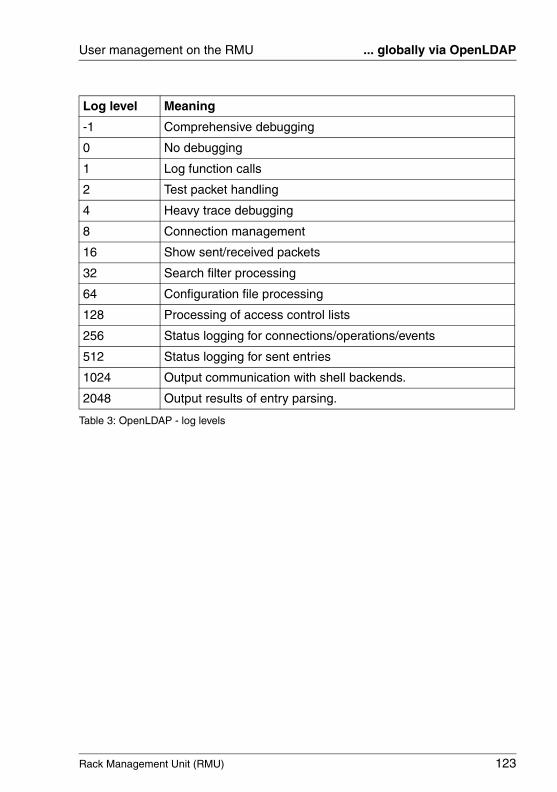
Rack Management Unit (RMU) 123
User management on the RMU ... globally via OpenLDAP
Log level Meaning
-1 Comprehensive debugging
0 No debugging
1 Log function calls
2 Test packet handling
4 Heavy trace debugging
8 Connection management
16 Show sent/received packets
32 Search filter processing
64 Configuration file processing
128 Processing of access control lists
256 Status logging for connections/operations/events
512 Status logging for sent entries
1024 Output communication with shell backends.
2048 Output results of entry parsing.
Table 3: OpenLDAP - log levels
124 Rack Management Unit (RMU)
Global email alerting User management on the RMU
© c
ogni
tas.
Ges
ells
chft
für
Tech
nik-
Dok
umen
tatio
n m
bH 2
009
Pfa
d: A
:\Ben
_Nev
is_R
MU
\Han
dbuc
h\en
\rm
u-en
.k04
4.4.8 Configuring email alerting to global RMU users
Email alerting to global RMU users is integrated in the global RMU user management system. This means that it can be configured and handled centrally for all platforms using a directory server. Appropriately configured global user IDs can receive email alerts from all RMUs that are connected to a directory server in the network.
I Prerequisites
The following requirements must be met for email alerting:
– A principal user must have been configured in the RMU web interface who has been granted permission to search in the LDAP tree (see section "Directory Service Configuration (LDAP) - Configuring the directory service at the RMU" on page 211).
– When configuring the LDAP settings on the Directory Service Configuration page (see page 211), email alerting must have been enabled under Directory Service Email Alert Configuration.
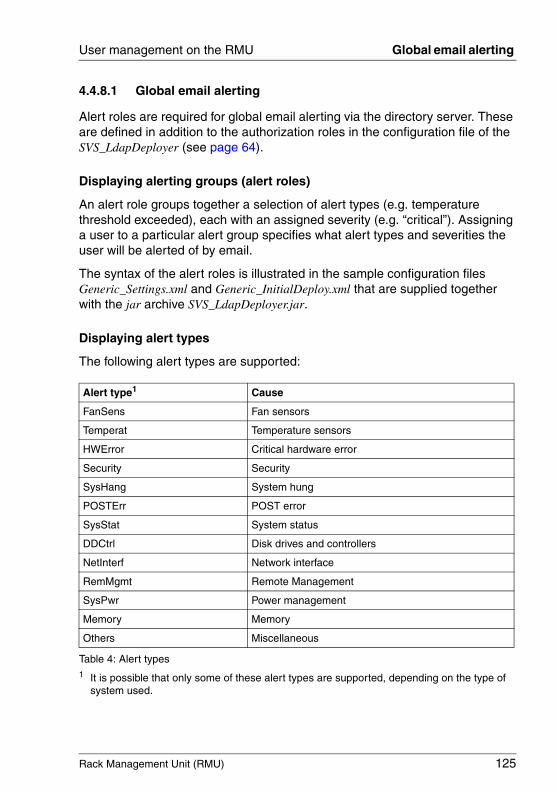
Rack Management Unit (RMU) 125
User management on the RMU Global email alerting
4.4.8.1 Global email alerting
Alert roles are required for global email alerting via the directory server. These are defined in addition to the authorization roles in the configuration file of the SVS_LdapDeployer (see page 64).
Displaying alerting groups (alert roles)
An alert role groups together a selection of alert types (e.g. temperature threshold exceeded), each with an assigned severity (e.g. “critical”). Assigning a user to a particular alert group specifies what alert types and severities the user will be alerted of by email.
The syntax of the alert roles is illustrated in the sample configuration files Generic_Settings.xml and Generic_InitialDeploy.xml that are supplied together with the jar archive SVS_LdapDeployer.jar.
Displaying alert types
The following alert types are supported:
Alert type1
1 It is possible that only some of these alert types are supported, depending on the type of system used.
Cause
FanSens Fan sensors
Temperat Temperature sensors
HWError Critical hardware error
Security Security
SysHang System hung
POSTErr POST error
SysStat System status
DDCtrl Disk drives and controllers
NetInterf Network interface
RemMgmt Remote Management
SysPwr Power management
Memory Memory
Others Miscellaneous
Table 4: Alert types
126 Rack Management Unit (RMU)
Global email alerting User management on the RMU
© c
ogni
tas.
Ges
ells
chft
für
Tech
nik-
Dok
umen
tatio
n m
bH 2
009
Pfa
d: A
:\Ben
_Nev
is_R
MU
\Han
dbuc
h\en
\rm
u-en
.k04
Each alert type can be assigned one of the following severity levels: Warning, Critical, All, (none).
Preferred mail server
For global email alerting, the setting Automatic is used on the preferred mail server: If the email cannot be successfully sent immediately, for instance if the first mail server is not available, the email is sent to the second mail server.
Supported mail formats
The following email formats are supported:
– Standard– Fixed Subject– ITS-Format– Fujitsu REMCS Format
I If a mail format other than Standard is used, you must add the users to the corresponding mail format group.
LDAP email table
If email alerting is configured (see page 128) and the option LDAP Email Alert Enable (see page 211) is selected, the RMU sends emails to the following users when an alert is issued:
– all appropriately configured local RMU users,
– all global RMU users registered in the LDAP email table for this alert.
The LDAP email table is initially created by the RMU firmware the first time the RMU is started and then updated at regular intervals. The size of the LDAP email table is limited to a maximum of 64 LDAP alert roles and a maximum of 64 global RMU users for whom email alerting is configured.
I It is recommended that you use email distribution lists for global email alerting.
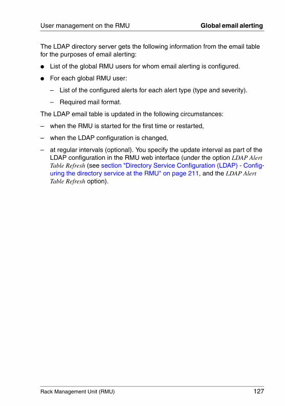
Rack Management Unit (RMU) 127
User management on the RMU Global email alerting
The LDAP directory server gets the following information from the email table for the purposes of email alerting:
● List of the global RMU users for whom email alerting is configured.
● For each global RMU user:
– List of the configured alerts for each alert type (type and severity).
– Required mail format.
The LDAP email table is updated in the following circumstances:
– when the RMU is started for the first time or restarted,
– when the LDAP configuration is changed,
– at regular intervals (optional). You specify the update interval as part of the LDAP configuration in the RMU web interface (under the option LDAP Alert Table Refresh (see section "Directory Service Configuration (LDAP) - Config-uring the directory service at the RMU" on page 211, and the LDAP Alert Table Refresh option).
128 Rack Management Unit (RMU)
Global email alerting User management on the RMU
© c
ogni
tas.
Ges
ells
chft
für
Tech
nik-
Dok
umen
tatio
n m
bH 2
009
Pfa
d: A
:\Ben
_Nev
is_R
MU
\Han
dbuc
h\en
\rm
u-en
.k04
Configuring global email alerting on the directory server
This section describes how to configure email alerting on the directory server.
I Settings must also be made for the RMU. You configure these in the RMU web interface (see section "Directory Service Configuration (LDAP) - Configuring the directory service at the RMU" on page 211).
Proceed as follows:
Ê In the directory service, enter the email addresses of the users to whom emails are to be sent.
I The method used to configure the email addresses differs depending on the directory service used (Active Directory, eDirectory or OpenLDAP).
Ê Create a configuration file in which the alert roles are defined.
Ê Start the SVS_LdapDeployer using this configuration file in order to generate a corresponding LDAP v2 structure (SVS) on the directory server (see page 65 and page 74).
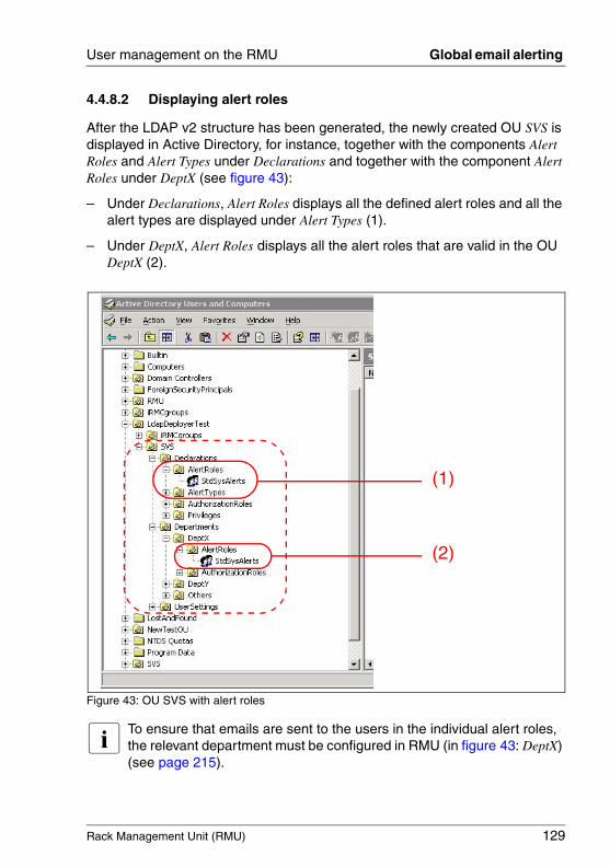
Rack Management Unit (RMU) 129
User management on the RMU Global email alerting
4.4.8.2 Displaying alert roles
After the LDAP v2 structure has been generated, the newly created OU SVS is displayed in Active Directory, for instance, together with the components Alert Roles and Alert Types under Declarations and together with the component Alert Roles under DeptX (see figure 43):
– Under Declarations, Alert Roles displays all the defined alert roles and all the alert types are displayed under Alert Types (1).
– Under DeptX, Alert Roles displays all the alert roles that are valid in the OU DeptX (2).
Figure 43: OU SVS with alert roles
I To ensure that emails are sent to the users in the individual alert roles, the relevant department must be configured in RMU (in figure 43: DeptX) (see page 215).
(1)
(2)
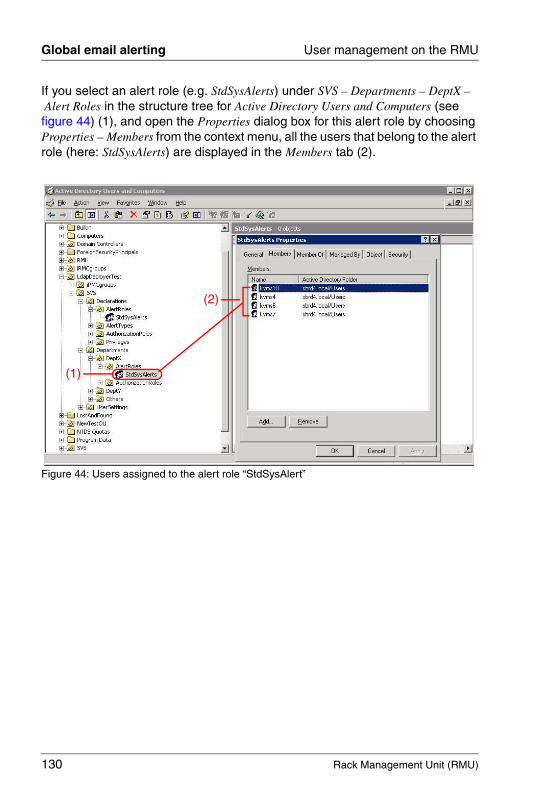
130 Rack Management Unit (RMU)
Global email alerting User management on the RMU
© c
ogni
tas.
Ges
ells
chft
für
Tech
nik-
Dok
umen
tatio
n m
bH 2
009
Pfa
d: A
:\Ben
_Nev
is_R
MU
\Han
dbuc
h\en
\rm
u-en
.k04
If you select an alert role (e.g. StdSysAlerts) under SVS – Departments – DeptX –Alert Roles in the structure tree for Active Directory Users and Computers (see figure 44) (1), and open the Properties dialog box for this alert role by choosing Properties – Members from the context menu, all the users that belong to the alert role (here: StdSysAlerts) are displayed in the Members tab (2).
Figure 44: Users assigned to the alert role “StdSysAlert”
(2)
(1)
Rack Management Unit (RMU) 131
User management on the RMU Global email alerting
4.4.8.3 Assigning RMU users to an alert role
You can assign RMU users to alert roles either
– on the basis of the user entry, or– on the basis of the role entry.
In the various different directory services (Microsoft Active Directory, Novell eDirectory and OpenLDAP), RMU users are assigned to RMU alert roles in the same way in which RMU users are assigned to RMU authorization roles and using the same tools.
In Active Directory, for instance, you make an assignment by clicking Add... in the Properties dialog box of the Active Directory Users and -Computers snap-in (see figure 44 on page 130).
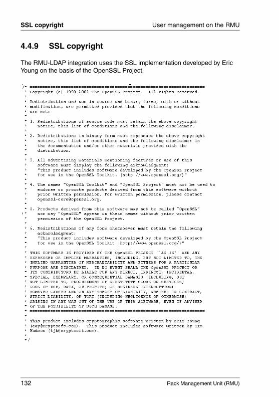
132 Rack Management Unit (RMU)
SSL copyright User management on the RMU
© c
ogni
tas.
Ges
ells
chft
für
Tech
nik-
Dok
umen
tatio
n m
bH 2
009
Pfa
d: A
:\Ben
_Nev
is_R
MU
\Han
dbuc
h\en
\rm
u-en
.k04
4.4.9 SSL copyright
The RMU-LDAP integration uses the SSL implementation developed by Eric Young on the basis of the OpenSSL Project.
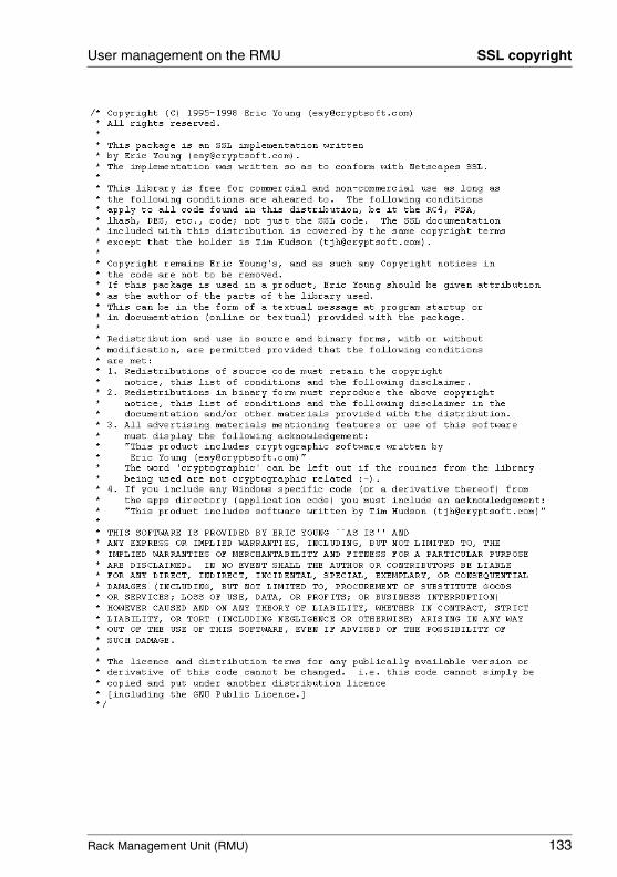
Rack Management Unit (RMU) 133
User management on the RMU SSL copyright

© c
ogni
tas.
Ges
ells
chft
für
Tech
nik-
Dok
umen
tatio
n m
bH 2
009
Pfa
d: A
:\Ben
_Nev
is_R
MU
\Han
dbuc
h\en
\rm
u-en
.k04
Rack Management Unit (RMU) 135
5 RMU web interfaceThe RMU not only has its own operating system, but also acts as a web server, providing its own interface. You can choose whether to show the menus and dialog boxes of the RMU web interface in German, English, or Japanese Language.
When you enter values in the RMU web interface, you always receive assis-tance in the form of tool tips.
I The software described below is based in part on the work of the Independent JPEG Group.
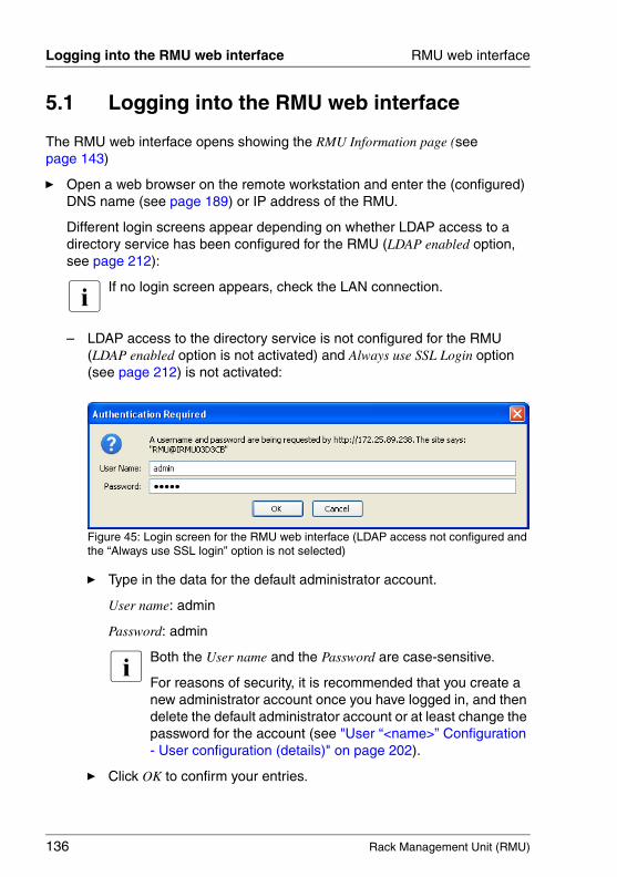
136 Rack Management Unit (RMU)
Logging into the RMU web interface RMU web interface
© c
ogni
tas.
Ges
ells
chft
für
Tech
nik-
Dok
umen
tatio
n m
bH 2
009
Pfa
d: A
:\Ben
_Nev
is_R
MU
\Han
dbuc
h\en
\rm
u-en
.k05
5.1 Logging into the RMU web interface
The RMU web interface opens showing the RMU Information page (see page 143)
Ê Open a web browser on the remote workstation and enter the (configured) DNS name (see page 189) or IP address of the RMU.
Different login screens appear depending on whether LDAP access to a directory service has been configured for the RMU (LDAP enabled option, see page 212):
I If no login screen appears, check the LAN connection.
– LDAP access to the directory service is not configured for the RMU (LDAP enabled option is not activated) and Always use SSL Login option (see page 212) is not activated:
Figure 45: Login screen for the RMU web interface (LDAP access not configured and the “Always use SSL login” option is not selected)
Ê Type in the data for the default administrator account.
User name: admin
Password: admin
I Both the User name and the Password are case-sensitive.
For reasons of security, it is recommended that you create a new administrator account once you have logged in, and then delete the default administrator account or at least change the password for the account (see "User “<name>” Configuration - User configuration (details)" on page 202).
Ê Click OK to confirm your entries.
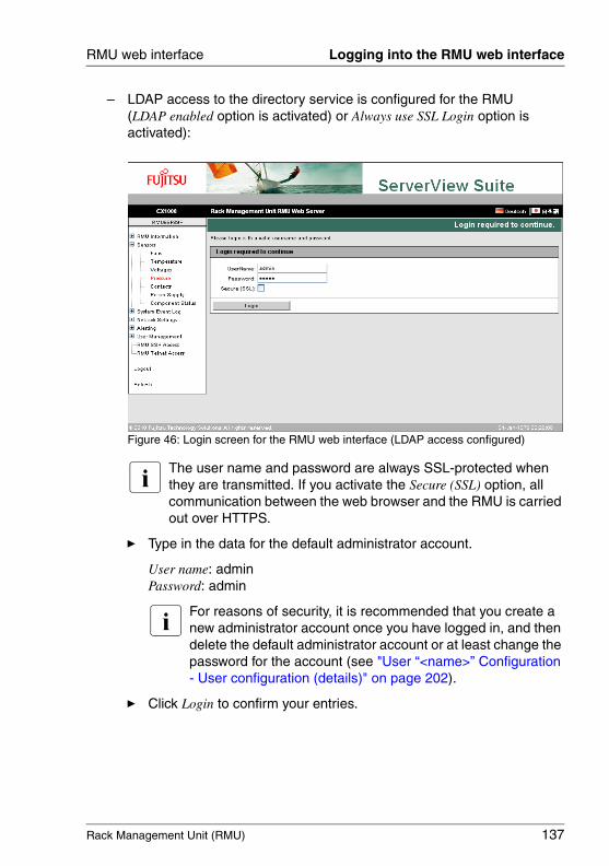
Rack Management Unit (RMU) 137
RMU web interface Logging into the RMU web interface
– LDAP access to the directory service is configured for the RMU(LDAP enabled option is activated) or Always use SSL Login option is activated):
Figure 46: Login screen for the RMU web interface (LDAP access configured)
I The user name and password are always SSL-protected when they are transmitted. If you activate the Secure (SSL) option, all communication between the web browser and the RMU is carried out over HTTPS.
Ê Type in the data for the default administrator account.
User name: adminPassword: admin
I For reasons of security, it is recommended that you create a new administrator account once you have logged in, and then delete the default administrator account or at least change the password for the account (see "User “<name>” Configuration - User configuration (details)" on page 202).
Ê Click Login to confirm your entries.

138 Rack Management Unit (RMU)
Required user permissions RMU web interface
© c
ogni
tas.
Ges
ells
chft
für
Tech
nik-
Dok
umen
tatio
n m
bH 2
009
Pfa
d: A
:\Ben
_Nev
is_R
MU
\Han
dbuc
h\en
\rm
u-en
.k05
5.2 Required user permissions
table 5 provides an overview of the permissions which are required in order to use the individual functions available at the RMU web interface.
Functions in the RMU web interface Permitted withIPMI privilege
level
Required permission
OE
M
Ad
min
istr
ato
r
Op
erat
or
Use
r
Co
nfi
gu
re U
ser
Acc
ou
nts
Co
nfi
gu
re R
MU
Set
tin
gs
Open the System Overview page. X X X X
Switch identification LED on/off. X X X X
Set Asset Tag Configuration. X
Open RMU Information page. X X X X
Reboot RMU. X X
Manually adjust RMU time X
Set Miscellaneous RMU Options X
Open and edit Certificate Upload page. X
Open and edit Generate a self signed RSA Certificate page X
Open RMU Firmware Update page. X X X X
Open and edit RMU TFTP Firmware Update. page X
Set firmware selector. X X X
Firmware update via Upload from filei X
RMU TFTP Einstellungen X
Open and edit the Fans page. X
Disable fan test (Fan Test group). X
Set Fan Check Time (Fan Test group). X
Open Temperature page X X X X
Define warning/critical level. X
Table 5: Permissions to use special the RMU web interface
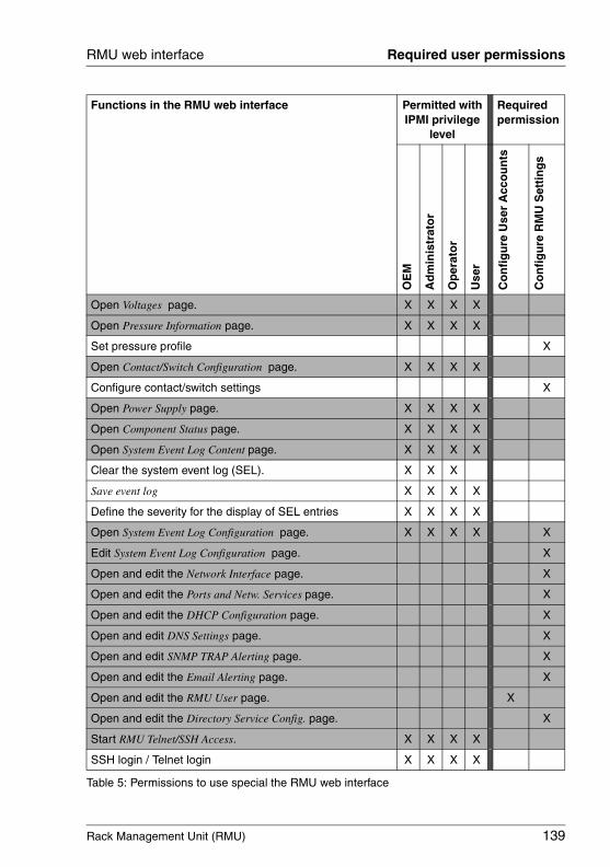
Rack Management Unit (RMU) 139
RMU web interface Required user permissions
Open Voltages page. X X X X
Open Pressure Information page. X X X X
Set pressure profile X
Open Contact/Switch Configuration page. X X X X
Configure contact/switch settings X
Open Power Supply page. X X X X
Open Component Status page. X X X X
Open System Event Log Content page. X X X X
Clear the system event log (SEL). X X X
Save event log X X X X
Define the severity for the display of SEL entries X X X X
Open System Event Log Configuration page. X X X X X
Edit System Event Log Configuration page. X
Open and edit the Network Interface page. X
Open and edit the Ports and Netw. Services page. X
Open and edit the DHCP Configuration page. X
Open and edit DNS Settings page. X
Open and edit SNMP TRAP Alerting page. X
Open and edit the Email Alerting page. X
Open and edit the RMU User page. X
Open and edit the Directory Service Config. page. X
Start RMU Telnet/SSH Access. X X X X
SSH login / Telnet login X X X X
Functions in the RMU web interface Permitted withIPMI privilege
level
Required permission
OE
M
Ad
min
istr
ato
r
Op
erat
or
Use
r
Co
nfi
gu
re U
ser
Acc
ou
nts
Co
nfi
gu
re R
MU
Set
tin
gs
Table 5: Permissions to use special the RMU web interface
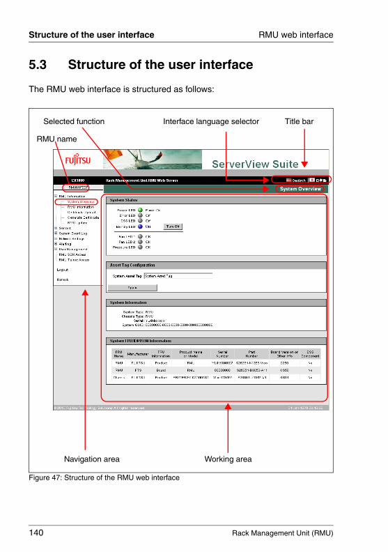
140 Rack Management Unit (RMU)
Structure of the user interface RMU web interface
© c
ogni
tas.
Ges
ells
chft
für
Tech
nik-
Dok
umen
tatio
n m
bH 2
009
Pfa
d: A
:\Ben
_Nev
is_R
MU
\Han
dbuc
h\en
\rm
u-en
.k05
5.3 Structure of the user interface
The RMU web interface is structured as follows:
Figure 47: Structure of the RMU web interface
Navigation area Working area
Selected function Title barInterface language selector
RMU name
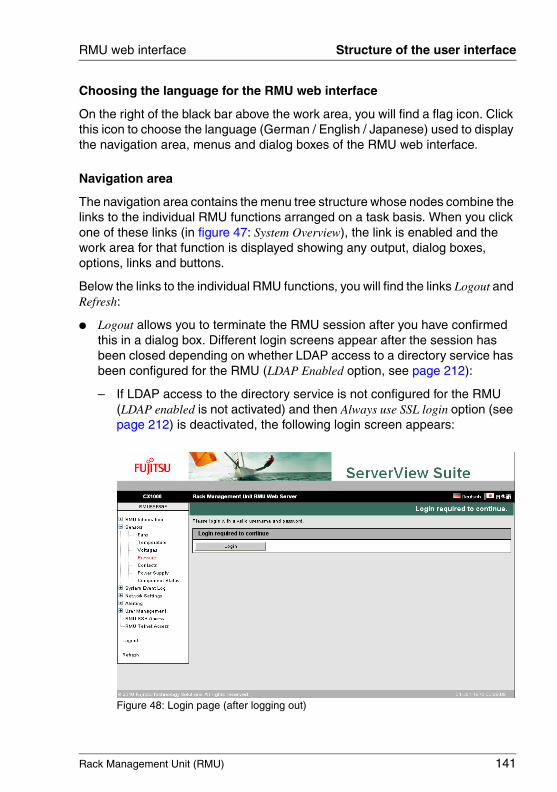
Rack Management Unit (RMU) 141
RMU web interface Structure of the user interface
Choosing the language for the RMU web interface
On the right of the black bar above the work area, you will find a flag icon. Click this icon to choose the language (German / English / Japanese) used to display the navigation area, menus and dialog boxes of the RMU web interface.
Navigation area
The navigation area contains the menu tree structure whose nodes combine the links to the individual RMU functions arranged on a task basis. When you click one of these links (in figure 47: System Overview), the link is enabled and the work area for that function is displayed showing any output, dialog boxes, options, links and buttons.
Below the links to the individual RMU functions, you will find the links Logout and Refresh:
● Logout allows you to terminate the RMU session after you have confirmed this in a dialog box. Different login screens appear after the session has been closed depending on whether LDAP access to a directory service has been configured for the RMU (LDAP Enabled option, see page 212):
– If LDAP access to the directory service is not configured for the RMU (LDAP enabled is not activated) and then Always use SSL login option (see page 212) is deactivated, the following login screen appears:
Figure 48: Login page (after logging out)
142 Rack Management Unit (RMU)
Structure of the user interface RMU web interface
© c
ogni
tas.
Ges
ells
chft
für
Tech
nik-
Dok
umen
tatio
n m
bH 2
009
Pfa
d: A
:\Ben
_Nev
is_R
MU
\Han
dbuc
h\en
\rm
u-en
.k05
Click the Login button to open the login screen of the RMU web interface (see figure 45 on page 136). This allows you to log in again if you wish.
– If LDAP access to the directory service is configured for the RMU (LDAP enabled option is activated) or the Always use SSL login option (see page 212) is activated, the appropriate login screen appears (see figure 46 on page 137).
● Click Refresh to refresh the contents of the RMU web interface.
I Alternatively, you can configure the interface to automatically update the contents periodically (see page 185).
Rack Management Unit (RMU) 143
RMU web interface RMU Information
5.4 RMU Information - Information on the RMU and the managed rack server
The RMU Information entry contains the links to the following pages:
– "System Overview - General information on the RMU and the managed rack server" on page 144
– "RMU Information - Information on the RMU" on page 149
– "Certificate Upload - Load the DSA/RSA certificate and private DSA/RSA key" on page 152
– "Generate a self-signed Certificate - Generate self-signed RSA certificate" on page 159
– "RMU Firmware Update" on page 161

144 Rack Management Unit (RMU)
RMU Information - System Overview RMU web interface
© c
ogni
tas.
Ges
ells
chft
für
Tech
nik-
Dok
umen
tatio
n m
bH 2
009
Pfa
d: A
:\Ben
_Nev
is_R
MU
\Han
dbuc
h\en
\rm
u-en
.k05
5.4.1 System Overview - General information on the RMU and the managed rack server
The System Overview page provides information on
– the system status of the rack server,– system (general information on the RMU),– system FRUs (Field Replaceable Units) / IDPROM.
In addition, the System Overview page allows you to enter a customer-specific asset tag for the managed rack system.
Figure 49: System Overview page
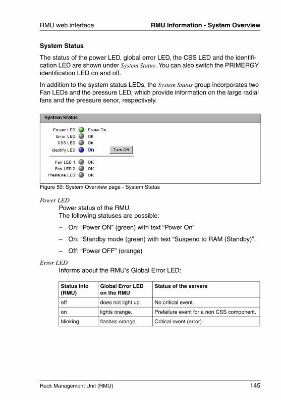
Rack Management Unit (RMU) 145
RMU web interface RMU Information - System Overview
System Status
The status of the power LED, global error LED, the CSS LED and the identifi-cation LED are shown under System Status. You can also switch the PRIMERGY identification LED on and off.
In addition to the system status LEDs, the System Status group incorporates two Fan LEDs and the pressure LED, which provide information on the large radial fans and the pressure senor, respectively.
Figure 50: System Overview page - System Status
Power LEDPower status of the RMU.The following statuses are possible:
– On: “Power ON” (green) with text “Power On”
– On: “Standby mode (green) with text “Suspend to RAM (Standby)”.
– Off: “Power OFF” (orange)
Error LEDInforms about the RMU‘s Global Error LED:
Status Info(RMU)
Global Error LEDon the RMU
Status of the servers
off does not light up. No critical event.
on lights orange. Prefailure event for a non CSS component.
blinking flashes orange. Critical event (error).
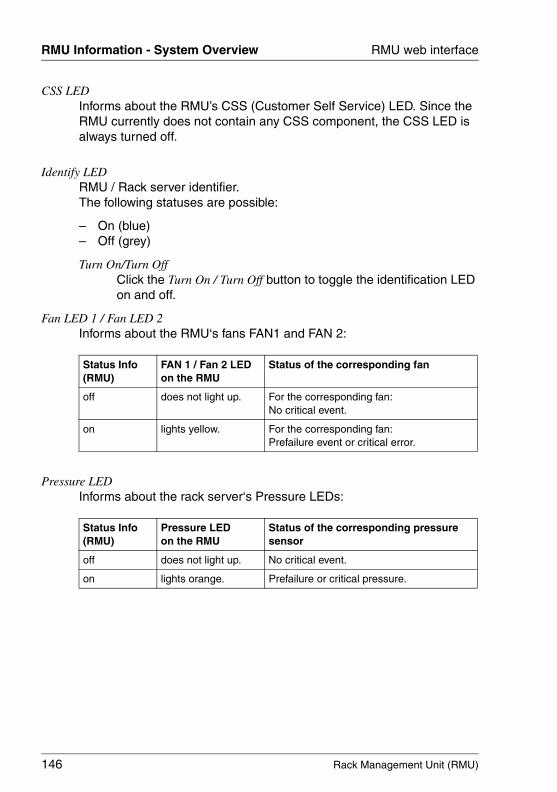
146 Rack Management Unit (RMU)
RMU Information - System Overview RMU web interface
© c
ogni
tas.
Ges
ells
chft
für
Tech
nik-
Dok
umen
tatio
n m
bH 2
009
Pfa
d: A
:\Ben
_Nev
is_R
MU
\Han
dbuc
h\en
\rm
u-en
.k05
CSS LEDInforms about the RMU’s CSS (Customer Self Service) LED. Since the RMU currently does not contain any CSS component, the CSS LED is always turned off.
Identify LEDRMU / Rack server identifier.The following statuses are possible:
– On (blue)– Off (grey)
Turn On/Turn OffClick the Turn On / Turn Off button to toggle the identification LED on and off.
Fan LED 1 / Fan LED 2Informs about the RMU‘s fans FAN1 and FAN 2:
Pressure LEDInforms about the rack server‘s Pressure LEDs:
Status Info(RMU)
FAN 1 / Fan 2 LEDon the RMU
Status of the corresponding fan
off does not light up. For the corresponding fan:No critical event.
on lights yellow. For the corresponding fan:Prefailure event or critical error.
Status Info(RMU)
Pressure LEDon the RMU
Status of the corresponding pressure sensor
off does not light up. No critical event.
on lights orange. Prefailure or critical pressure.

Rack Management Unit (RMU) 147
RMU web interface RMU Information - System Overview
Asset Tag Configuration
Under Asset Tag Configuration, you can enter a customer-specific asset tag for the managed rack system.
I The customer-specific asset tag allows you to assign the managed rack system an inventory number or other identifier of your choice.
With Windows-based systems, this customer-specific asset tag is provided automatically by the WMI (Windows Management Instrumen-tation). It can then be evaluated by in-house tools or used for integration in enterprise management systems (such as CA Unicenter).
Figure 51: The System Overview - System Status page
System Asset TagYou can enter the asset tag here.
Ê Click Apply to accept the asset tag.
System Information
System Information lists information on the RMU.
Figure 52: System Overview page - System Information
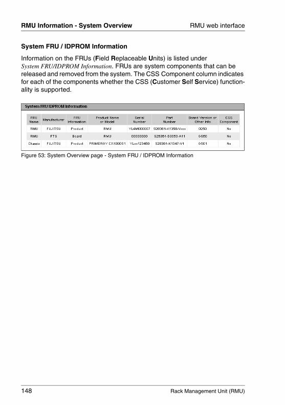
148 Rack Management Unit (RMU)
RMU Information - System Overview RMU web interface
© c
ogni
tas.
Ges
ells
chft
für
Tech
nik-
Dok
umen
tatio
n m
bH 2
009
Pfa
d: A
:\Ben
_Nev
is_R
MU
\Han
dbuc
h\en
\rm
u-en
.k05
System FRU / IDPROM Information
Information on the FRUs (Field Replaceable Units) is listed under System FRU/IDPROM Information. FRUs are system components that can be released and removed from the system. The CSS Component column indicates for each of the components whether the CSS (Customer Self Service) function-ality is supported.
Figure 53: System Overview page - System FRU / IDPROM Information
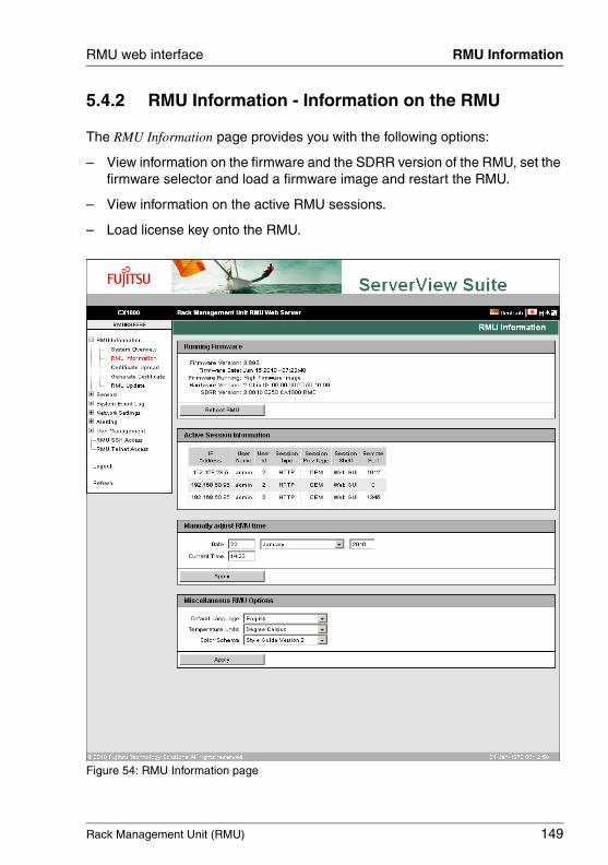
Rack Management Unit (RMU) 149
RMU web interface RMU Information
5.4.2 RMU Information - Information on the RMU
The RMU Information page provides you with the following options:
– View information on the firmware and the SDRR version of the RMU, set the firmware selector and load a firmware image and restart the RMU.
– View information on the active RMU sessions.
– Load license key onto the RMU.
Figure 54: RMU Information page
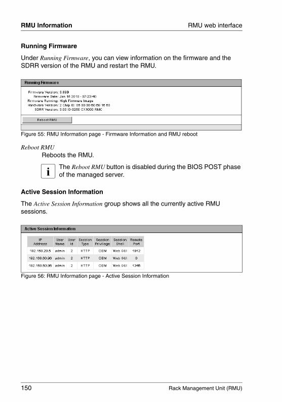
150 Rack Management Unit (RMU)
RMU Information RMU web interface
© c
ogni
tas.
Ges
ells
chft
für
Tech
nik-
Dok
umen
tatio
n m
bH 2
009
Pfa
d: A
:\Ben
_Nev
is_R
MU
\Han
dbuc
h\en
\rm
u-en
.k05
Running Firmware
Under Running Firmware, you can view information on the firmware and the SDRR version of the RMU and restart the RMU.
Figure 55: RMU Information page - Firmware Information and RMU reboot
Reboot RMU Reboots the RMU.
I The Reboot RMU button is disabled during the BIOS POST phase of the managed server.
Active Session Information
The Active Session Information group shows all the currently active RMU sessions.
Figure 56: RMU Information page - Active Session Information

Rack Management Unit (RMU) 151
RMU web interface RMU Information
Manually adjust RMU time
The Manually adjust RMU time group allows you to enter the RMU time settings.
Figure 57: RMU Information page - License Key
Ê Click Apply to activate the specified RMU time.
Miscellaneous RMU Options
The Miscellaneous RMU Options group allows you to make settings for the layout of the RMU web interface.
Figure 58: RMU Information page - Miscellaneous Options
Default LanguageSpecifies the language (German / English / Japanese) that is set as default the next time the RMU web interface is called. However, changing the interface language is always possible within a browser session ("on the fly").
Temperature UnitsSpecifies the unit used for displaying temperature values at the RMU web interface (degrees Celsius / degrees Fahrenheit). This setting applies for the current session and is preset the next time the RMU web interface is called.
Colour SchemaSpecifies the color scheme for displaying the RMU web interface. This setting applies for all currently active sessions and is preset the next time the RMU web interface is called.
152 Rack Management Unit (RMU)
RMU Information - Certificate Upload RMU web interface
© c
ogni
tas.
Ges
ells
chft
für
Tech
nik-
Dok
umen
tatio
n m
bH 2
009
Pfa
d: A
:\Ben
_Nev
is_R
MU
\Han
dbuc
h\en
\rm
u-en
.k05
5.4.3 Certificate Upload - Load the DSA/RSA certificate and private DSA/RSA key
The Certificate Upload page allows you to load a signed X.509 DSA/RSA certif-icate (SSL) from a Certificate Authority (CA) and/or your private DSA/RSA key (SSH) onto the RMU.
I The RMU is supplied with a predefined server certificate (default certif-icate). If you want to access the RMU over secure SSL/SSH connections, it is recommended that you replace the certificate with one signed by a Certificate Authority (CA) as soon as possible.
I Input format of the X.509 DSA/RSA certificate and the private DSA/RSA key:
The X.509 DSA/RSA certificate and the RSA/DSA must both be available in PEM-encoded format (ASCII/Base64).
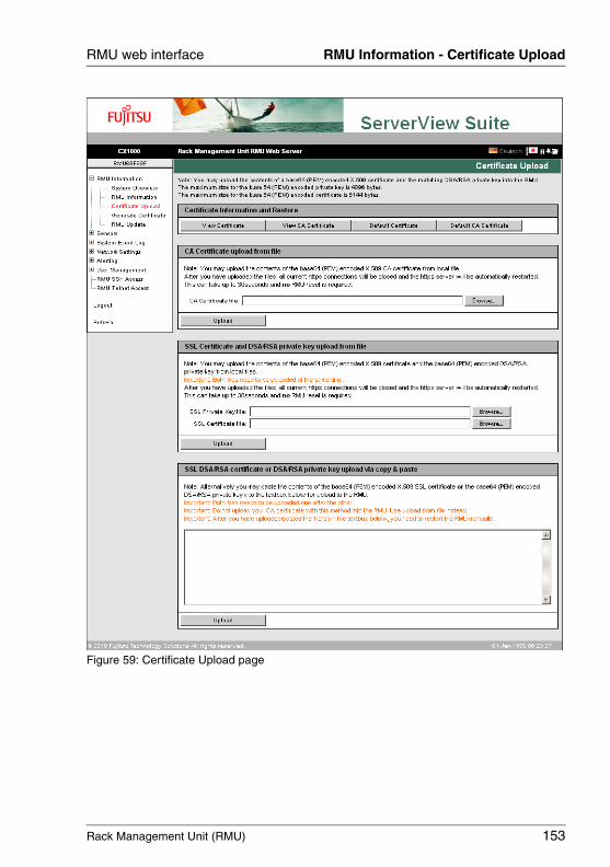
Rack Management Unit (RMU) 153
RMU web interface RMU Information - Certificate Upload
Figure 59: Certificate Upload page
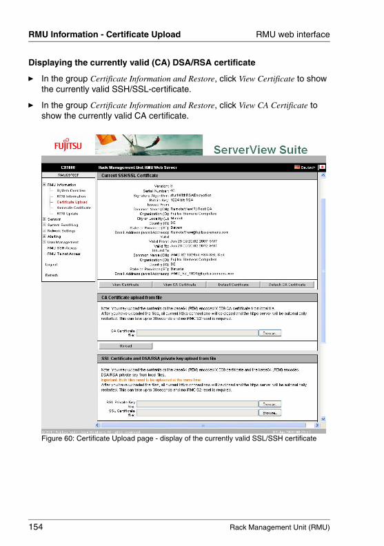
154 Rack Management Unit (RMU)
RMU Information - Certificate Upload RMU web interface
© c
ogni
tas.
Ges
ells
chft
für
Tech
nik-
Dok
umen
tatio
n m
bH 2
009
Pfa
d: A
:\Ben
_Nev
is_R
MU
\Han
dbuc
h\en
\rm
u-en
.k05
Displaying the currently valid (CA) DSA/RSA certificate
Ê In the group Certificate Information and Restore, click View Certificate to show the currently valid SSH/SSL-certificate.
Ê In the group Certificate Information and Restore, click View CA Certificate to show the currently valid CA certificate.
Figure 60: Certificate Upload page - display of the currently valid SSL/SSH certificate
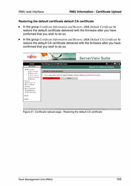
Rack Management Unit (RMU) 155
RMU web interface RMU Information - Certificate Upload
Restoring the default certificate default CA certificate
Ê In the group Certificate Information and Restore, click Default Certificate to restore the default certificate delivered with the firmware after you have confirmed that you wish to do so.
Ê In the group Certificate Information and Restore, click Default CA Certificate to restore the default CA certificate delivered with the firmware after you have confirmed that you wish to do so.
Figure 61: Certificate Upload page - Restoring the default CA certificate

156 Rack Management Unit (RMU)
RMU Information - Certificate Upload RMU web interface
© c
ogni
tas.
Ges
ells
chft
für
Tech
nik-
Dok
umen
tatio
n m
bH 2
009
Pfa
d: A
:\Ben
_Nev
is_R
MU
\Han
dbuc
h\en
\rm
u-en
.k05
Loading a CA certificate from a local file
Use the CA Certificate upload from file group to load a CA certificate from a local file.
Figure 62: Loading a CA certificate from a local file
Proceed as follows:
Ê Save the CA certificate in a local file on the managed server.
Ê Specify this file under CA Certificate File by clicking the associated Browse... button and navigating to the file containing the CA certificate.
Ê Click the Upload button to load the certificate and/or the private key onto the RMU.
I When you upload the certificate and/or private key, all the existing HTTPS connections are closed and the HTTPS server is automati-cally restarted. This process can take up to 30 seconds. No explicit reset of the RMU is required.
Ê Click the View CA Certificate button to make sure that the certificate has been loaded successfully.
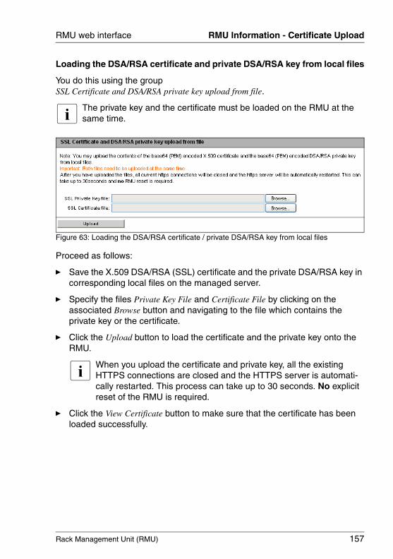
Rack Management Unit (RMU) 157
RMU web interface RMU Information - Certificate Upload
Loading the DSA/RSA certificate and private DSA/RSA key from local files
You do this using the group SSL Certificate and DSA/RSA private key upload from file.
I The private key and the certificate must be loaded on the RMU at the same time.
Figure 63: Loading the DSA/RSA certificate / private DSA/RSA key from local files
Proceed as follows:
Ê Save the X.509 DSA/RSA (SSL) certificate and the private DSA/RSA key in corresponding local files on the managed server.
Ê Specify the files Private Key File and Certificate File by clicking on the associated Browse button and navigating to the file which contains the private key or the certificate.
Ê Click the Upload button to load the certificate and the private key onto the RMU.
I When you upload the certificate and private key, all the existing HTTPS connections are closed and the HTTPS server is automati-cally restarted. This process can take up to 30 seconds. No explicit reset of the RMU is required.
Ê Click the View Certificate button to make sure that the certificate has been loaded successfully.
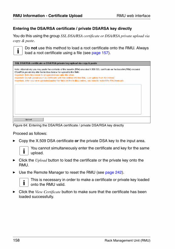
158 Rack Management Unit (RMU)
RMU Information - Certificate Upload RMU web interface
© c
ogni
tas.
Ges
ells
chft
für
Tech
nik-
Dok
umen
tatio
n m
bH 2
009
Pfa
d: A
:\Ben
_Nev
is_R
MU
\Han
dbuc
h\en
\rm
u-en
.k05
Entering the DSA/RSA certificate / private DSARSA key directly
You do this using the group SSL DSA/RSA certificate or DSA/RSA private upload via copy & paste.
I Do not use this method to load a root certificate onto the RMU. Always load a root certificate using a file (see page 157).
Figure 64: Entering the DSA/RSA certificate / private DSA/RSA key directly
Proceed as follows:
Ê Copy the X.509 DSA certificate or the private DSA key to the input area.
I You cannot simultaneously enter the certificate and key for the same upload.
Ê Click the Upload button to load the certificate or the private key onto the RMU.
Ê Use the Remote Manager to reset the RMU (see page 242).
I This is necessary in order to make a certificate or private key loaded onto the RMU valid.
Ê Click the View Certificate button to make sure that the certificate has been loaded successfully.
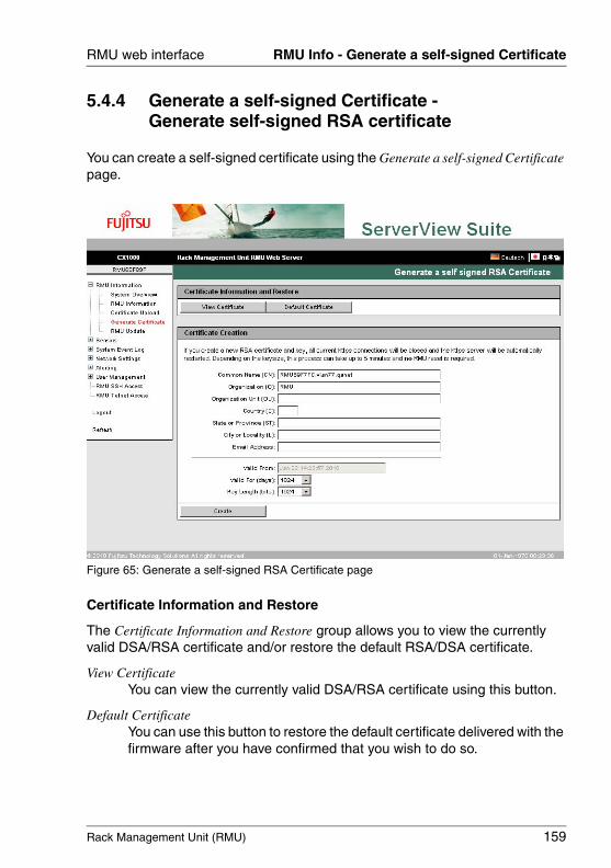
Rack Management Unit (RMU) 159
RMU web interface RMU Info - Generate a self-signed Certificate
5.4.4 Generate a self-signed Certificate - Generate self-signed RSA certificate
You can create a self-signed certificate using the Generate a self-signed Certificate page.
Figure 65: Generate a self-signed RSA Certificate page
Certificate Information and Restore
The Certificate Information and Restore group allows you to view the currently valid DSA/RSA certificate and/or restore the default RSA/DSA certificate.
View CertificateYou can view the currently valid DSA/RSA certificate using this button.
Default CertificateYou can use this button to restore the default certificate delivered with the firmware after you have confirmed that you wish to do so.
160 Rack Management Unit (RMU)
RMU Info - Generate a self-signed Certificate RMU web interface
© c
ogni
tas.
Ges
ells
chft
für
Tech
nik-
Dok
umen
tatio
n m
bH 2
009
Pfa
d: A
:\Ben
_Nev
is_R
MU
\Han
dbuc
h\en
\rm
u-en
.k05
Certificate Creation
Proceed as follows to create a self-signed certificate:
Ê Enter the requisite details under Certificate Creation.
Ê Click Create to create the certificate.
I When generating the new certificate, all the existing HTTPS connec-tions are closed and the HTTPS server is automatically restarted. This can take up to 5 minutes depending on the key length. No explicit reset of the RMU is required.
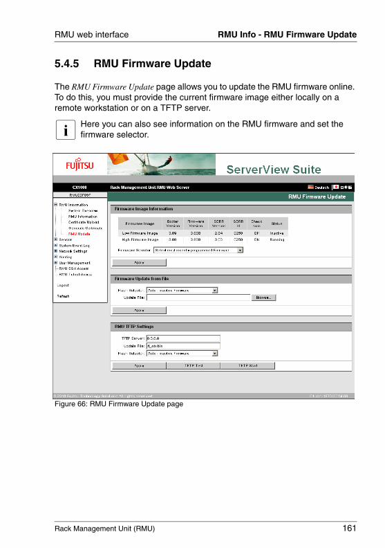
Rack Management Unit (RMU) 161
RMU web interface RMU Info - RMU Firmware Update
5.4.5 RMU Firmware Update
The RMU Firmware Update page allows you to update the RMU firmware online. To do this, you must provide the current firmware image either locally on a remote workstation or on a TFTP server.
I Here you can also see information on the RMU firmware and set the firmware selector.
Figure 66: RMU Firmware Update page
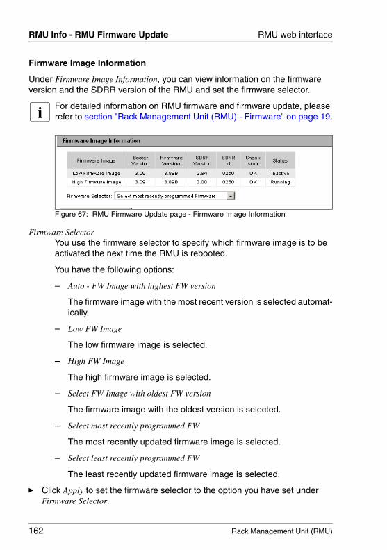
162 Rack Management Unit (RMU)
RMU Info - RMU Firmware Update RMU web interface
© c
ogni
tas.
Ges
ells
chft
für
Tech
nik-
Dok
umen
tatio
n m
bH 2
009
Pfa
d: A
:\Ben
_Nev
is_R
MU
\Han
dbuc
h\en
\rm
u-en
.k05
Firmware Image Information
Under Firmware Image Information, you can view information on the firmware version and the SDRR version of the RMU and set the firmware selector.
I For detailed information on RMU firmware and firmware update, please refer to section "Rack Management Unit (RMU) - Firmware" on page 19.
Figure 67: RMU Firmware Update page - Firmware Image Information
Firmware Selector You use the firmware selector to specify which firmware image is to be activated the next time the RMU is rebooted.
You have the following options:
– Auto - FW Image with highest FW version
The firmware image with the most recent version is selected automat-ically.
– Low FW Image
The low firmware image is selected.
– High FW Image
The high firmware image is selected.
– Select FW Image with oldest FW version
The firmware image with the oldest version is selected.
– Select most recently programmed FW
The most recently updated firmware image is selected.
– Select least recently programmed FW
The least recently updated firmware image is selected.
Ê Click Apply to set the firmware selector to the option you have set under Firmware Selector.
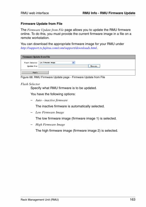
Rack Management Unit (RMU) 163
RMU web interface RMU Info - RMU Firmware Update
Firmware Update from File
The Firmware Update from File page allows you to update the RMU firmware online. To do this, you must provide the current firmware image in a file on a remote workstation.
You can download the appropriate firmware image for your RMU under http://support.ts.fujitsu.com/com/support/downloads.html.
Figure 68: RMU Firmware Update page - Firmware Update from File
Flash SelectorSpecify what RMU firmware is to be updated.
You have the following options:
– Auto - inactive firmware
The inactive firmware is automatically selected.
– Low Firmware Image
The low firmware image (firmware image 1) is selected.
– High Firmware Image
The high firmware image (firmware image 2) is selected.
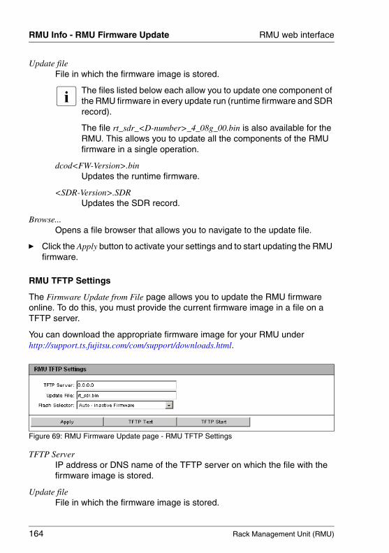
164 Rack Management Unit (RMU)
RMU Info - RMU Firmware Update RMU web interface
© c
ogni
tas.
Ges
ells
chft
für
Tech
nik-
Dok
umen
tatio
n m
bH 2
009
Pfa
d: A
:\Ben
_Nev
is_R
MU
\Han
dbuc
h\en
\rm
u-en
.k05
Update fileFile in which the firmware image is stored.
I The files listed below each allow you to update one component of the RMU firmware in every update run (runtime firmware and SDR record).
The file rt_sdr_<D-number>_4_08g_00.bin is also available for the RMU. This allows you to update all the components of the RMU firmware in a single operation.
dcod<FW-Version>.binUpdates the runtime firmware.
<SDR-Version>.SDRUpdates the SDR record.
Browse...Opens a file browser that allows you to navigate to the update file.
Ê Click the Apply button to activate your settings and to start updating the RMU firmware.
RMU TFTP Settings
The Firmware Update from File page allows you to update the RMU firmware online. To do this, you must provide the current firmware image in a file on a TFTP server.
You can download the appropriate firmware image for your RMU under http://support.ts.fujitsu.com/com/support/downloads.html.
Figure 69: RMU Firmware Update page - RMU TFTP Settings
TFTP ServerIP address or DNS name of the TFTP server on which the file with the firmware image is stored.
Update fileFile in which the firmware image is stored.
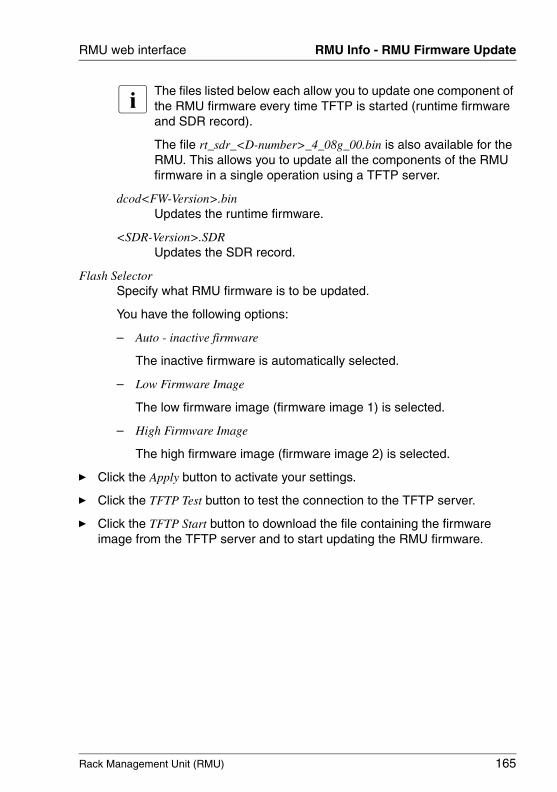
Rack Management Unit (RMU) 165
RMU web interface RMU Info - RMU Firmware Update
I The files listed below each allow you to update one component of the RMU firmware every time TFTP is started (runtime firmware and SDR record).
The file rt_sdr_<D-number>_4_08g_00.bin is also available for the RMU. This allows you to update all the components of the RMU firmware in a single operation using a TFTP server.
dcod<FW-Version>.binUpdates the runtime firmware.
<SDR-Version>.SDRUpdates the SDR record.
Flash SelectorSpecify what RMU firmware is to be updated.
You have the following options:
– Auto - inactive firmware
The inactive firmware is automatically selected.
– Low Firmware Image
The low firmware image (firmware image 1) is selected.
– High Firmware Image
The high firmware image (firmware image 2) is selected.
Ê Click the Apply button to activate your settings.
Ê Click the TFTP Test button to test the connection to the TFTP server.
Ê Click the TFTP Start button to download the file containing the firmware image from the TFTP server and to start updating the RMU firmware.
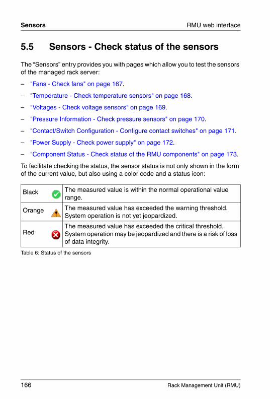
166 Rack Management Unit (RMU)
Sensors RMU web interface
© c
ogni
tas.
Ges
ells
chft
für
Tech
nik-
Dok
umen
tatio
n m
bH 2
009
Pfa
d: A
:\Ben
_Nev
is_R
MU
\Han
dbuc
h\en
\rm
u-en
.k05
5.5 Sensors - Check status of the sensors
The “Sensors” entry provides you with pages which allow you to test the sensors of the managed rack server:
– "Fans - Check fans" on page 167.
– "Temperature - Check temperature sensors" on page 168.
– "Voltages - Check voltage sensors" on page 169.
– "Pressure Information - Check pressure sensors" on page 170.
– "Contact/Switch Configuration - Configure contact switches" on page 171.
– "Power Supply - Check power supply" on page 172.
– "Component Status - Check status of the RMU components" on page 173.
To facilitate checking the status, the sensor status is not only shown in the form of the current value, but also using a color code and a status icon:
Black The measured value is within the normal operational value range.
Orange The measured value has exceeded the warning threshold. System operation is not yet jeopardized.
Red The measured value has exceeded the critical threshold. System operation may be jeopardized and there is a risk of loss of data integrity.
Table 6: Status of the sensors
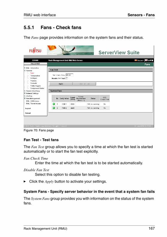
Rack Management Unit (RMU) 167
RMU web interface Sensors - Fans
5.5.1 Fans - Check fans
The Fans page provides information on the system fans and their status.
Figure 70: Fans page
Fan Test - Test fans
The Fan Test group allows you to specify a time at which the fan test is started automatically or to start the fan test explicitly.
Fan Check TimeEnter the time at which the fan test is to be started automatically.
Disable Fan TestSelect this option to disable fan testing.
Ê Click the Apply button to activate your settings.
System Fans - Specify server behavior in the event that a system fan fails
The System Fans group provides you with information on the status of the system fans.

168 Rack Management Unit (RMU)
Sensors - Temperature RMU web interface
© c
ogni
tas.
Ges
ells
chft
für
Tech
nik-
Dok
umen
tatio
n m
bH 2
009
Pfa
d: A
:\Ben
_Nev
is_R
MU
\Han
dbuc
h\en
\rm
u-en
.k05
5.5.2 Temperature - Check temperature sensors
The Temperatur page provides information on the status of the temperature sensors which measure the temperature at the RMU, ambient temperature, and exhaust temperature.
Figure 71: Temperature page
Warning LevelTemperature level (of the corresponding sensor) from which on
– a "warning" icon (orange) will be displayed in this Temperature page entry,
– a SEL entry with will be generated (severity level Major).
Critical LevelTemperature level of the corresponding sensor from which on
– a "critical" icon (red) will be displayed in this Temperature page entry,
– a SEL entry with will be generated (severity level Critical).
Ê Click Apply the to activate your settings.
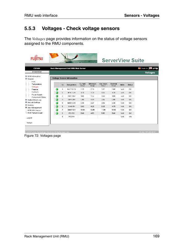
Rack Management Unit (RMU) 169
RMU web interface Sensors - Voltages
5.5.3 Voltages - Check voltage sensors
The Voltages page provides information on the status of voltage sensors assigned to the RMU components.
Figure 72: Voltages page
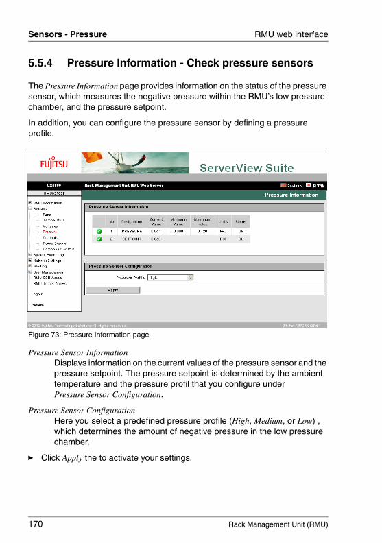
170 Rack Management Unit (RMU)
Sensors - Pressure RMU web interface
© c
ogni
tas.
Ges
ells
chft
für
Tech
nik-
Dok
umen
tatio
n m
bH 2
009
Pfa
d: A
:\Ben
_Nev
is_R
MU
\Han
dbuc
h\en
\rm
u-en
.k05
5.5.4 Pressure Information - Check pressure sensors
The Pressure Information page provides information on the status of the pressure sensor, which measures the negative pressure within the RMU’s low pressure chamber, and the pressure setpoint.
In addition, you can configure the pressure sensor by defining a pressure profile.
Figure 73: Pressure Information page
Pressure Sensor InformationDisplays information on the current values of the pressure sensor and the pressure setpoint. The pressure setpoint is determined by the ambient temperature and the pressure profil that you configure under Pressure Sensor Configuration.
Pressure Sensor Configuration Here you select a predefined pressure profile (High, Medium, or Low) , which determines the amount of negative pressure in the low pressure chamber.
Ê Click Apply the to activate your settings.

Rack Management Unit (RMU) 171
RMU web interface Sensors - Contact/Switch Configuration
5.5.5 Contact/Switch Configuration - Configure contact switches
The Contact/Switch Configuration page allows you to configure monitoring of the GPIO inputs that are provided via the 6-pin terminal on the RMU’s rear panel (see page 18).
Figure 74: Contact/Switch Configuration page
Contact 1 /contact 2 / Contact 3 Specify user defined names of the general purpose input switches contact switches on the RMU’s rear panel.
Contact active Specifies whether the corresponding contact switch is Active or Inactive.
Ê Click Apply the to activate your settings.
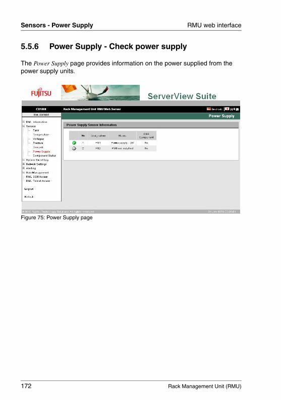
172 Rack Management Unit (RMU)
Sensors - Power Supply RMU web interface
© c
ogni
tas.
Ges
ells
chft
für
Tech
nik-
Dok
umen
tatio
n m
bH 2
009
Pfa
d: A
:\Ben
_Nev
is_R
MU
\Han
dbuc
h\en
\rm
u-en
.k05
5.5.6 Power Supply - Check power supply
The Power Supply page provides information on the power supplied from the power supply units.
Figure 75: Power Supply page
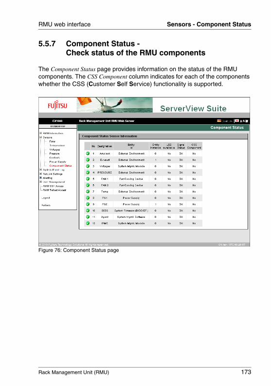
Rack Management Unit (RMU) 173
RMU web interface Sensors - Component Status
5.5.7 Component Status - Check status of the RMU components
The Component Status page provides information on the status of the RMU components. The CSS Component column indicates for each of the components whether the CSS (Customer Self Service) functionality is supported.
Figure 76: Component Status page
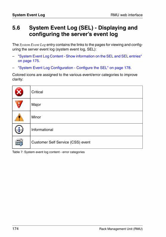
174 Rack Management Unit (RMU)
System Event Log RMU web interface
© c
ogni
tas.
Ges
ells
chft
für
Tech
nik-
Dok
umen
tatio
n m
bH 2
009
Pfa
d: A
:\Ben
_Nev
is_R
MU
\Han
dbuc
h\en
\rm
u-en
.k05
5.6 System Event Log (SEL) - Displaying and configuring the server’s event log
The System Event Log entry contains the links to the pages for viewing and config-uring the server event log (system event log, SEL):
– "System Event Log Content - Show information on the SEL and SEL entries" on page 175.
– "System Event Log Configuration - Configure the SEL" on page 178.
Colored icons are assigned to the various event/error categories to improve clarity:
Critical
Major
Minor
Informational
Customer Self Service (CSS) event
Table 7: System event log content - error categories
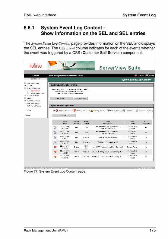
Rack Management Unit (RMU) 175
RMU web interface System Event Log
5.6.1 System Event Log Content - Show information on the SEL and SEL entries
The System Event Log Content page provides information on the SEL and displays the SEL entries. The CSS Event column indicates for each of the events whether the event was triggered by a CSS (Customer Self Service) component.
Figure 77: System Event Log Content page
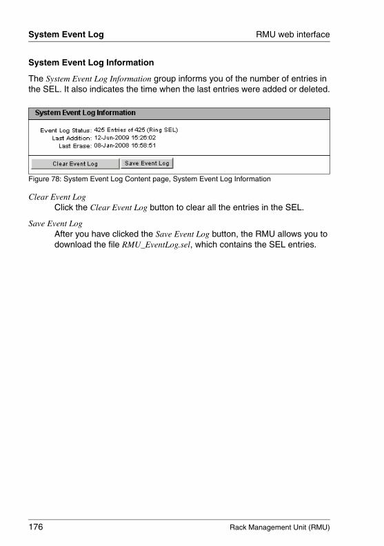
176 Rack Management Unit (RMU)
System Event Log RMU web interface
© c
ogni
tas.
Ges
ells
chft
für
Tech
nik-
Dok
umen
tatio
n m
bH 2
009
Pfa
d: A
:\Ben
_Nev
is_R
MU
\Han
dbuc
h\en
\rm
u-en
.k05
System Event Log Information
The System Event Log Information group informs you of the number of entries in the SEL. It also indicates the time when the last entries were added or deleted.
Figure 78: System Event Log Content page, System Event Log Information
Clear Event LogClick the Clear Event Log button to clear all the entries in the SEL.
Save Event LogAfter you have clicked the Save Event Log button, the RMU allows you to download the file RMU_EventLog.sel, which contains the SEL entries.
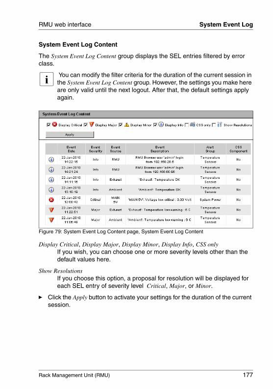
Rack Management Unit (RMU) 177
RMU web interface System Event Log
System Event Log Content
The System Event Log Content group displays the SEL entries filtered by error class.
I You can modify the filter criteria for the duration of the current session in the System Event Log Content group. However, the settings you make here are only valid until the next logout. After that, the default settings apply again.
Figure 79: System Event Log Content page, System Event Log Content
Display Critical, Display Major, Display Minor, Display Info, CSS onlyIf you wish, you can choose one or more severity levels other than the default values here.
Show ResolutionsIf you choose this option, a proposal for resolution will be displayed for each SEL entry of severity level Critical, Major, or Minor.
Ê Click the Apply button to activate your settings for the duration of the current session.

178 Rack Management Unit (RMU)
System Event Log RMU web interface
© c
ogni
tas.
Ges
ells
chft
für
Tech
nik-
Dok
umen
tatio
n m
bH 2
009
Pfa
d: A
:\Ben
_Nev
is_R
MU
\Han
dbuc
h\en
\rm
u-en
.k05
5.6.2 System Event Log Configuration - Configure the SEL
On the System Event Log Configuration page, you can configure
– the SEL entries which are displayed by default on the System Event Log Content page (see page 175).
– whether the SEL is organized as a ring buffer or a linear buffer.
Figure 80: System Event Log Configuration page
Display Critical, Display Major, Display Minor, Display Info, CSS onlyHere you select one or more severity levels for which SEL entries should be displayed by default on the System Event Log Content page.
Show ResolutionsIf you choose this option, a proposal for resolution will be displayed for each SEL entry of severity level Critical, Major, or Minor.
Ring SELThe SEL is organized as a ring buffer.
IPMI SELThe SEL is organized as a linear buffer.
I When the linear SEL has been completely filled, it is not possible to add any further entries.
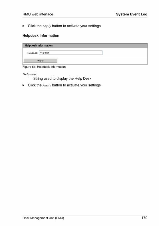
Rack Management Unit (RMU) 179
RMU web interface System Event Log
Ê Click the Apply button to activate your settings.
Helpdesk Information
Figure 81: Helpdesk Information
Help deskString used to display the Help Desk
Ê Click the Apply button to activate your settings.
180 Rack Management Unit (RMU)
Network Settings RMU web interface
© c
ogni
tas.
Ges
ells
chft
für
Tech
nik-
Dok
umen
tatio
n m
bH 2
009
Pfa
d: A
:\Ben
_Nev
is_R
MU
\Han
dbuc
h\en
\rm
u-en
.k05
5.7 Network Settings - Configure the LAN parameters
The Network Settings entry brings together the links to the pages you use to configure the LAN parameters of the RMU:
– "Network Interface - Configure Ethernet settings on the RMU" on page 181.
– "Ports and Network Services - Configuring ports and network services" on page 184.
– "DHCP Configuration - Configuring the host name for the RMU" on page 187.
– "DNS Settings - Enable DNS for the RMU" on page 189.
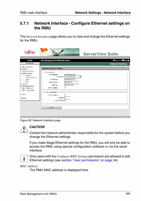
Rack Management Unit (RMU) 181
RMU web interface Network Settings - Network Interface
5.7.1 Network Interface - Configure Ethernet settings on the RMU
The Network Interface page allows you to view and change the Ethernet settings for the RMU.
Figure 82: Network Interface page
V CAUTION!
Contact the network administrator responsible for the system before you change the Ethernet settings.
If you make illegal Ethernet settings for the RMU, you will only be able to access the RMU using special configuration software or via the serial interface.
I Only users with the Configure RMU Settings permission are allowed to edit Ethernet settings (see section "User permissions" on page 34).
MAC AddressThe RMU MAC address is displayed here.
182 Rack Management Unit (RMU)
Network Settings - Network Interface RMU web interface
© c
ogni
tas.
Ges
ells
chft
für
Tech
nik-
Dok
umen
tatio
n m
bH 2
009
Pfa
d: A
:\Ben
_Nev
is_R
MU
\Han
dbuc
h\en
\rm
u-en
.k05
LAN SpeedLAN speed. The following options are available:
– Auto Negotiation– 100 MBit/s Full Duplex– 100 MBit/s Half Duplex– 10 MBit/s Full Duplex– 10 MBit/s Half Duplex
If Auto Negotiation is selected, the onboard LAN controller assigned to the RMU autonomously determines the correct transfer speed and duplex method for the network port it is connected to.
IP AddressThe IP address of the RMU in the LAN. This address is different from the IP address of the managed server.
I If you are working with a static address (DHCP enable option not activated) then you can enter this here. Otherwise (if the DHCP enable option is activated), the RMU only uses the field to display the address.
Subnet Mask Subnet mask of the RMU in the LAN.
Gateway IP address of the default gateway in the LAN.
Rack Management Unit (RMU) 183
RMU web interface Network Settings - Network Interface
DHCP EnabledIf you activate this option, the RMU gets its LAN settings from a DHCP server on the network.
I Do not activate the DHCP option if no DHCP server is available on the network.If you activate the DHCP option and there is no DHCP server available on the network, the RMU goes into a search loop (i.e. it continues searching for a DHCP server until it finds one).
The (configured) RMU can be registered with a DNS server by an appropriately configured DHCP server (see sections "DHCP Configuration - Configuring the host name for the RMU" on page 187 and "DNS Settings - Enable DNS for the RMU" on page 189).
VLAN EnabledThis option allows you to activate VLAN support for the RMU.
VLAN IdVLAN ID of the virtual network (VLAN) the RMU belongs to. Permitted value range: 1 Î VLAN Id Î 4094.
VLAN PriorityVLAN priority (user priority) of the RMU in the VLAN specified by VLAN Id.Permitted value range: 0 Î VLAN Priority Î 7 (default: 0).
Ê Click the Apply button to activate the configured Ethernet settings.
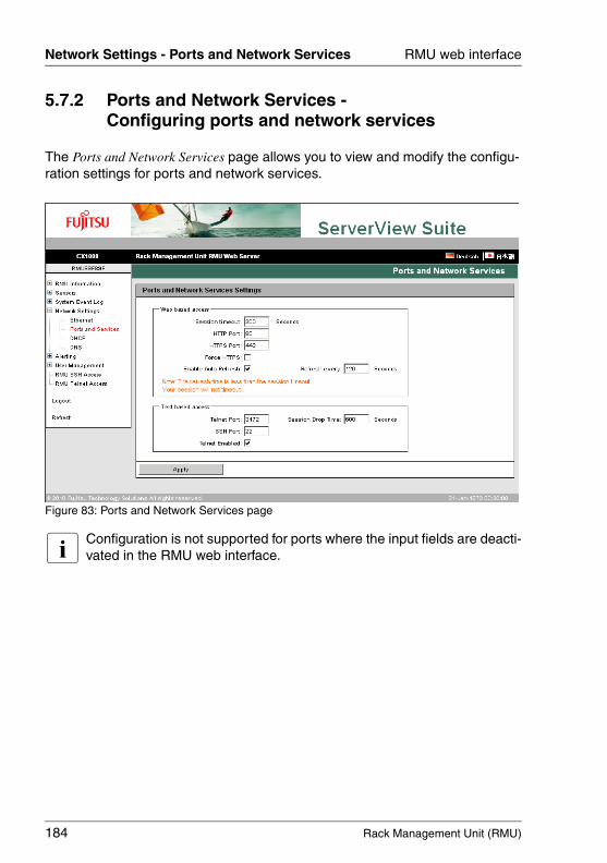
184 Rack Management Unit (RMU)
Network Settings - Ports and Network Services RMU web interface
© c
ogni
tas.
Ges
ells
chft
für
Tech
nik-
Dok
umen
tatio
n m
bH 2
009
Pfa
d: A
:\Ben
_Nev
is_R
MU
\Han
dbuc
h\en
\rm
u-en
.k05
5.7.2 Ports and Network Services - Configuring ports and network services
The Ports and Network Services page allows you to view and modify the configu-ration settings for ports and network services.
Figure 83: Ports and Network Services page
I Configuration is not supported for ports where the input fields are deacti-vated in the RMU web interface.
Rack Management Unit (RMU) 185
RMU web interface Network Settings - Ports and Network Services
Ports for web-based access
Session TimeoutPeriod of inactivity (in seconds) after which the session is automatically closed. The login page of the RMU web interface then appears, and you can log in again as required (see page 136).
I Your session will not automatically be closed if it is inactive when the time specified in Session Timeout has elapsed if you enter a value for the refresh interval which is less than the Session Timeout in the Refresh every ... seconds field (see page 186).
HTTP PortHTTP port of the RMUDefault port number: 80Configurable: yesEnabled by default: yesCommunication direction: inbound and outbound
HTTPS Port HTTPS (HTTP Secure) port of the RMUDefault port number: 443Configurable: yesEnabled by default: yesCommunication direction: inbound and outbound
Force HTTPSIf you enable the Force HTTPS option, users can only establish a secure connection to the RMU on the HTTPS port specified in the entry field.
If you disable the Force HTTPS option, users can establish a non-secure connection to the RMU on the HTTP port specified in the entry field.
I If the SSL certificate has expired, a message to this effect is issued in the browser.
Enable Auto RefreshIf you activate this option, the contents of the RMU web interface are automatically refreshed periodically. Specify the refresh interval in the Refresh every ... seconds field.
186 Rack Management Unit (RMU)
Network Settings - Ports and Network Services RMU web interface
© c
ogni
tas.
Ges
ells
chft
für
Tech
nik-
Dok
umen
tatio
n m
bH 2
009
Pfa
d: A
:\Ben
_Nev
is_R
MU
\Han
dbuc
h\en
\rm
u-en
.k05
Refresh every ... secondsLength (in seconds) of the interval for automatically refreshing the RMU web interface.
I If you enter a value for the refresh interval which is less than the Session Timeout (see page 185), your session will not automatically be closed when the time specified in Session Timeout has elapsed in the event of inactivity.
Ports for text-based access
Telnet PortTelnet port of the RMUDefault port number: 3172Configurable: yesEnabled by default: noCommunication direction: inbound and outbound
Session Drop TimePeriod of inactivity (in seconds) after which a Telnet connection is automatically cleared.
SSH PortSSH (Secure Shell) port of the RMU Default port number: 22Configurable: yesEnabled by default: yesCommunication direction: inbound and outbound
Telnet enabledIf you enable the Telnet Enabled option, users can establish a connection to the RMU on the Telnet port specified in the entry field.
Ê Click the Apply button to store the configured settings.
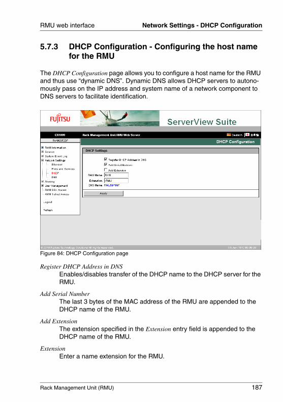
Rack Management Unit (RMU) 187
RMU web interface Network Settings - DHCP Configuration
5.7.3 DHCP Configuration - Configuring the host name for the RMU
The DHCP Configuration page allows you to configure a host name for the RMU and thus use “dynamic DNS”. Dynamic DNS allows DHCP servers to autono-mously pass on the IP address and system name of a network component to DNS servers to facilitate identification.
Figure 84: DHCP Configuration page
Register DHCP Address in DNSEnables/disables transfer of the DHCP name to the DHCP server for the RMU.
Add Serial NumberThe last 3 bytes of the MAC address of the RMU are appended to the DHCP name of the RMU.
Add ExtensionThe extension specified in the Extension entry field is appended to the DHCP name of the RMU.
ExtensionEnter a name extension for the RMU.
188 Rack Management Unit (RMU)
Network Settings - DHCP Configuration RMU web interface
© c
ogni
tas.
Ges
ells
chft
für
Tech
nik-
Dok
umen
tatio
n m
bH 2
009
Pfa
d: A
:\Ben
_Nev
is_R
MU
\Han
dbuc
h\en
\rm
u-en
.k05
RMU NameRMU name passed to DHCP for the RMU in place of the server name.
DNS NameShows the configured DNS name for the RMU.
Ê Click the Apply button to store the configured settings.
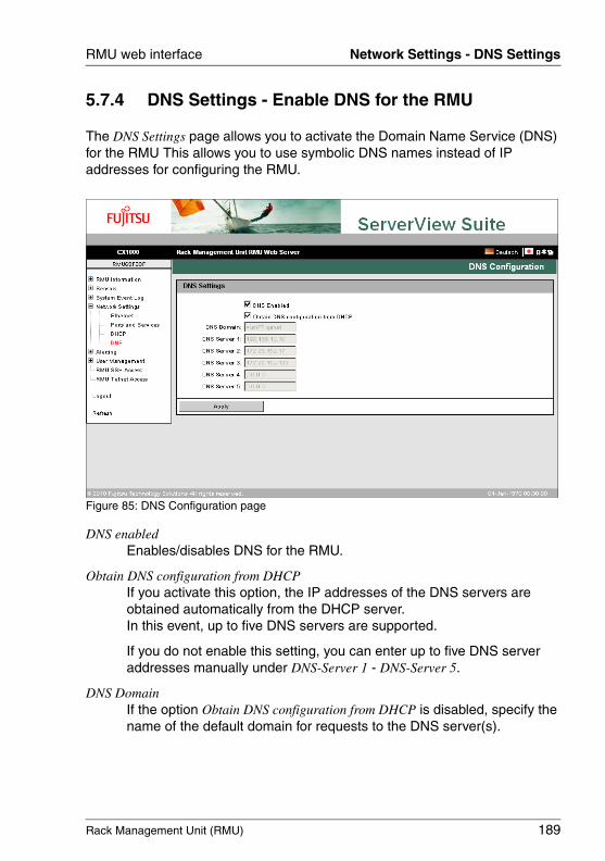
Rack Management Unit (RMU) 189
RMU web interface Network Settings - DNS Settings
5.7.4 DNS Settings - Enable DNS for the RMU
The DNS Settings page allows you to activate the Domain Name Service (DNS) for the RMU This allows you to use symbolic DNS names instead of IP addresses for configuring the RMU.
Figure 85: DNS Configuration page
DNS enabled Enables/disables DNS for the RMU.
Obtain DNS configuration from DHCPIf you activate this option, the IP addresses of the DNS servers are obtained automatically from the DHCP server.In this event, up to five DNS servers are supported.
If you do not enable this setting, you can enter up to five DNS server addresses manually under DNS-Server 1 - DNS-Server 5.
DNS DomainIf the option Obtain DNS configuration from DHCP is disabled, specify the name of the default domain for requests to the DNS server(s).
190 Rack Management Unit (RMU)
Network Settings - DNS Settings RMU web interface
© c
ogni
tas.
Ges
ells
chft
für
Tech
nik-
Dok
umen
tatio
n m
bH 2
009
Pfa
d: A
:\Ben
_Nev
is_R
MU
\Han
dbuc
h\en
\rm
u-en
.k05
DNS Server 1 .. 5If the Obtain DNS configuration from DHCP option is disabled, you can enter the names of up to five DNS servers here.
Ê Click the Apply button to store the configured settings.
Rack Management Unit (RMU) 191
RMU web interface Alerting
5.8 Alerting - Configure alerting
The Alerting entry contains the links to the pages you use to configure alerting for the RMU:
– "SNMP Trap Alerting - Configure SNMP trap alerting" on page 192.
– "Email Alerting - Configure email alerting" on page 193.
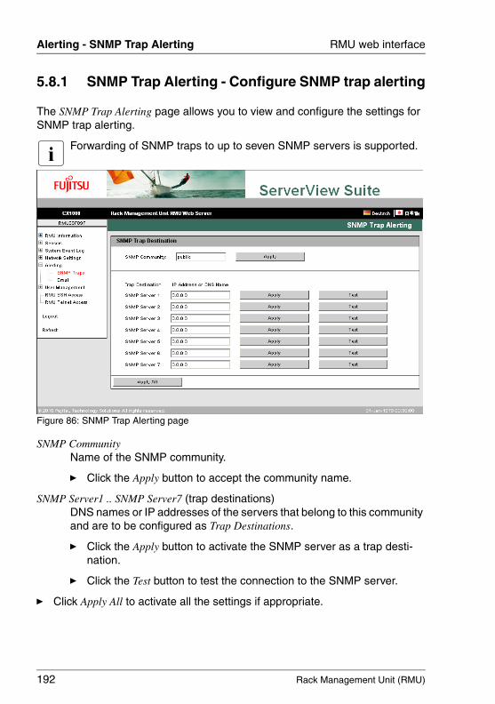
192 Rack Management Unit (RMU)
Alerting - SNMP Trap Alerting RMU web interface
© c
ogni
tas.
Ges
ells
chft
für
Tech
nik-
Dok
umen
tatio
n m
bH 2
009
Pfa
d: A
:\Ben
_Nev
is_R
MU
\Han
dbuc
h\en
\rm
u-en
.k05
5.8.1 SNMP Trap Alerting - Configure SNMP trap alerting
The SNMP Trap Alerting page allows you to view and configure the settings for SNMP trap alerting.
I Forwarding of SNMP traps to up to seven SNMP servers is supported.
Figure 86: SNMP Trap Alerting page
SNMP CommunityName of the SNMP community.
Ê Click the Apply button to accept the community name.
SNMP Server1 .. SNMP Server7 (trap destinations)DNS names or IP addresses of the servers that belong to this community and are to be configured as Trap Destinations.
Ê Click the Apply button to activate the SNMP server as a trap desti-nation.
Ê Click the Test button to test the connection to the SNMP server.
Ê Click Apply All to activate all the settings if appropriate.
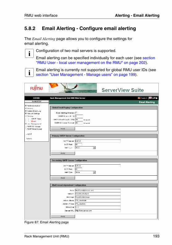
Rack Management Unit (RMU) 193
RMU web interface Alerting - Email Alerting
5.8.2 Email Alerting - Configure email alerting
The Email Alerting page allows you to configure the settings for email alerting.
I Configuration of two mail servers is supported.
Email alerting can be specified individually for each user (see section "RMU User - local user management on the RMU" on page 202).
I Email alerting is currently not supported for global RMU user IDs (see section "User Management - Manage users" on page 199).
Figure 87: Email Alerting page
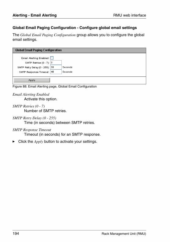
194 Rack Management Unit (RMU)
Alerting - Email Alerting RMU web interface
© c
ogni
tas.
Ges
ells
chft
für
Tech
nik-
Dok
umen
tatio
n m
bH 2
009
Pfa
d: A
:\Ben
_Nev
is_R
MU
\Han
dbuc
h\en
\rm
u-en
.k05
Global Email Paging Configuration - Configure global email settings
The Global Email Paging Configuration group allows you to configure the global email settings.
Figure 88: Email Alerting page, Global Email Configuration
Email Alerting EnabledActivate this option.
SMTP Retries (0 - 7)Number of SMTP retries.
SMTP Retry Delay (0 - 255)Time (in seconds) between SMTP retries.
SMTP Response TimeoutTimeout (in seconds) for an SMTP response.
Ê Click the Apply button to activate your settings.
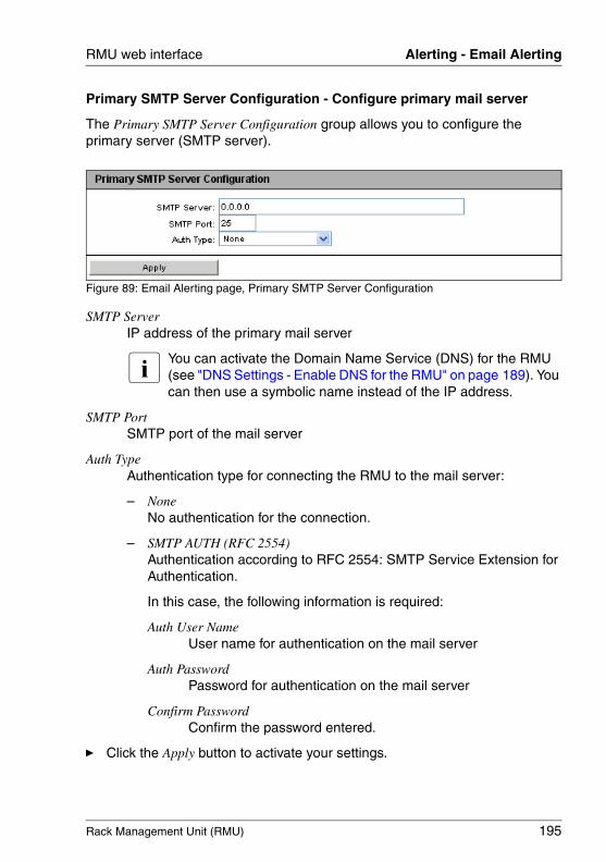
Rack Management Unit (RMU) 195
RMU web interface Alerting - Email Alerting
Primary SMTP Server Configuration - Configure primary mail server
The Primary SMTP Server Configuration group allows you to configure the primary server (SMTP server).
Figure 89: Email Alerting page, Primary SMTP Server Configuration
SMTP ServerIP address of the primary mail server
I You can activate the Domain Name Service (DNS) for the RMU (see "DNS Settings - Enable DNS for the RMU" on page 189). You can then use a symbolic name instead of the IP address.
SMTP PortSMTP port of the mail server
Auth TypeAuthentication type for connecting the RMU to the mail server:
– None No authentication for the connection.
– SMTP AUTH (RFC 2554) Authentication according to RFC 2554: SMTP Service Extension for Authentication.
In this case, the following information is required:
Auth User NameUser name for authentication on the mail server
Auth PasswordPassword for authentication on the mail server
Confirm PasswordConfirm the password entered.
Ê Click the Apply button to activate your settings.
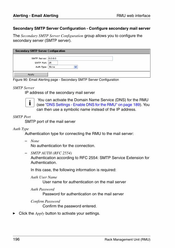
196 Rack Management Unit (RMU)
Alerting - Email Alerting RMU web interface
© c
ogni
tas.
Ges
ells
chft
für
Tech
nik-
Dok
umen
tatio
n m
bH 2
009
Pfa
d: A
:\Ben
_Nev
is_R
MU
\Han
dbuc
h\en
\rm
u-en
.k05
Secondary SMTP Server Configuration - Configure secondary mail server
The Secondary SMTP Server Configuration group allows you to configure the secondary server (SMTP server).
Figure 90: Email Alerting page - Secondary SMTP Server Configuration
SMTP ServerIP address of the secondary mail server
I You can activate the Domain Name Service (DNS) for the RMU (see "DNS Settings - Enable DNS for the RMU" on page 189). You can then use a symbolic name instead of the IP address.
SMTP PortSMTP port of the mail server
Auth TypeAuthentication type for connecting the RMU to the mail server:
– None No authentication for the connection.
– SMTP AUTH (RFC 2554) Authentication according to RFC 2554: SMTP Service Extension for Authentication.
In this case, the following information is required:
Auth User NameUser name for authentication on the mail server
Auth PasswordPassword for authentication on the mail server
Confirm PasswordConfirm the password entered.
Ê Click the Apply button to activate your settings.
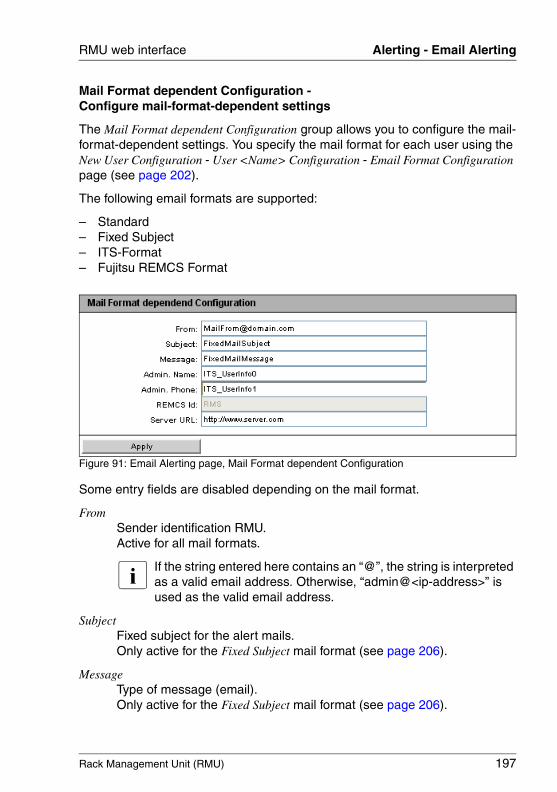
Rack Management Unit (RMU) 197
RMU web interface Alerting - Email Alerting
Mail Format dependent Configuration - Configure mail-format-dependent settings
The Mail Format dependent Configuration group allows you to configure the mail-format-dependent settings. You specify the mail format for each user using the New User Configuration - User <Name> Configuration - Email Format Configuration page (see page 202).
The following email formats are supported:
– Standard– Fixed Subject– ITS-Format– Fujitsu REMCS Format
Figure 91: Email Alerting page, Mail Format dependent Configuration
Some entry fields are disabled depending on the mail format.
FromSender identification RMU.Active for all mail formats.
I If the string entered here contains an “@”, the string is interpreted as a valid email address. Otherwise, “admin@<ip-address>” is used as the valid email address.
SubjectFixed subject for the alert mails.Only active for the Fixed Subject mail format (see page 206).
MessageType of message (email).Only active for the Fixed Subject mail format (see page 206).
198 Rack Management Unit (RMU)
Alerting - Email Alerting RMU web interface
© c
ogni
tas.
Ges
ells
chft
für
Tech
nik-
Dok
umen
tatio
n m
bH 2
009
Pfa
d: A
:\Ben
_Nev
is_R
MU
\Han
dbuc
h\en
\rm
u-en
.k05
Admin NameName of the administrator responsible (optional).Only active for the ITS mail format (see page 206).
Admin PhonePhone number of the administrator responsible (optional).Only active for the ITS mail format (see page 206).
REMCS IdThis ID is an additional server ID, similar to the serial number.Only active for the mail format Fujitsu REMCS-Format.
Server URLAdditional URL of the RACK system (optional). You have to enter the URL manually.Only active for the Standard mail format.
Ê Click the Apply button to store your settings.
Rack Management Unit (RMU) 199
RMU web interface User Management
5.9 User Management - Manage users
The User Management entry contains the links to the pages for local user management as well as for the configuration of the directory service for global user management (LDAP configuration):
– "RMU User - local user management on the RMU" on page 200.
– "Directory Service Configuration (LDAP) - Configuring the directory service at the RMU" on page 211.
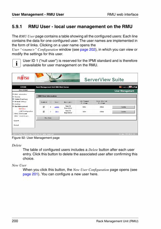
200 Rack Management Unit (RMU)
User Management - RMU User RMU web interface
© c
ogni
tas.
Ges
ells
chft
für
Tech
nik-
Dok
umen
tatio
n m
bH 2
009
Pfa
d: A
:\Ben
_Nev
is_R
MU
\Han
dbuc
h\en
\rm
u-en
.k05
5.9.1 RMU User - local user management on the RMU
The RMU User page contains a table showing all the configured users: Each line contains the data for one configured user. The user names are implemented in the form of links. Clicking on a user name opens the User “<name>” Configuration window (see page 202), in which you can view or modify the settings for this user.
I User ID 1 (“null user”) is reserved for the IPMI standard and is therefore unavailable for user management on the RMU.
Figure 92: User Management page
DeleteThe table of configured users includes a Delete button after each user entry. Click this button to delete the associated user after confirming this choice.
New UserWhen you click this button, the New User Configuration page opens (see page 201). You can configure a new user here.
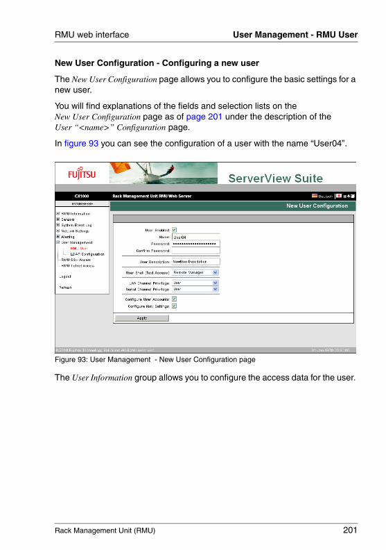
Rack Management Unit (RMU) 201
RMU web interface User Management - RMU User
New User Configuration - Configuring a new user
The New User Configuration page allows you to configure the basic settings for a new user.
You will find explanations of the fields and selection lists on the New User Configuration page as of page 201 under the description of the User “<name>” Configuration page.
In figure 93 you can see the configuration of a user with the name “User04”.
Figure 93: User Management - New User Configuration page
The User Information group allows you to configure the access data for the user.
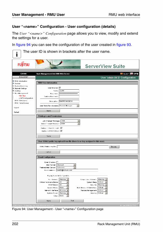
202 Rack Management Unit (RMU)
User Management - RMU User RMU web interface
© c
ogni
tas.
Ges
ells
chft
für
Tech
nik-
Dok
umen
tatio
n m
bH 2
009
Pfa
d: A
:\Ben
_Nev
is_R
MU
\Han
dbuc
h\en
\rm
u-en
.k05
User “<name>” Configuration - User configuration (details)
The User “<name>” Configuration page allows you to view, modify and extend the settings for a user.
In figure 94 you can see the configuration of the user created in figure 93.
I The user ID is shown in brackets after the user name.
Figure 94: User Management - User “<name>” Configuration page
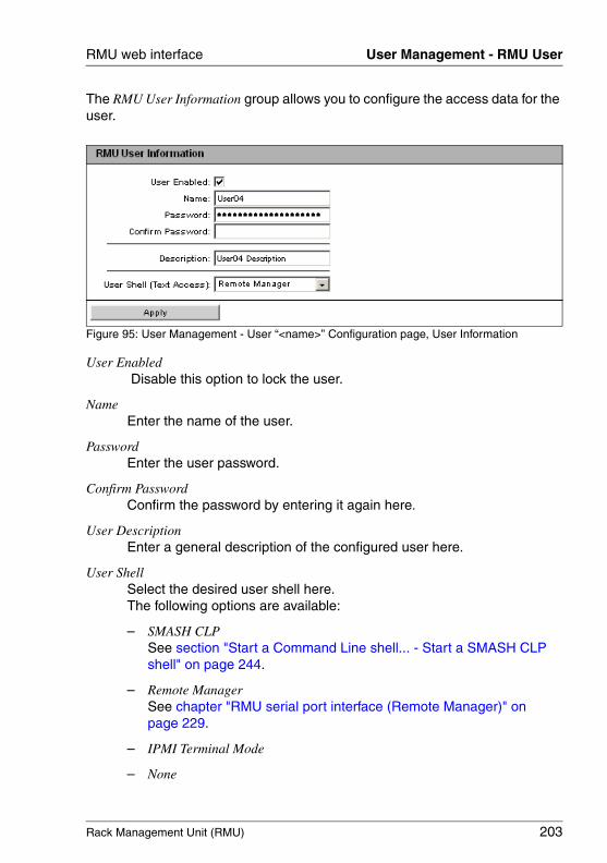
Rack Management Unit (RMU) 203
RMU web interface User Management - RMU User
The RMU User Information group allows you to configure the access data for the user.
Figure 95: User Management - User “<name>” Configuration page, User Information
User Enabled Disable this option to lock the user.
Name Enter the name of the user.
PasswordEnter the user password.
Confirm PasswordConfirm the password by entering it again here.
User DescriptionEnter a general description of the configured user here.
User ShellSelect the desired user shell here. The following options are available:
– SMASH CLPSee section "Start a Command Line shell... - Start a SMASH CLP shell" on page 244.
– Remote ManagerSee chapter "RMU serial port interface (Remote Manager)" on page 229.
– IPMI Terminal Mode
– None
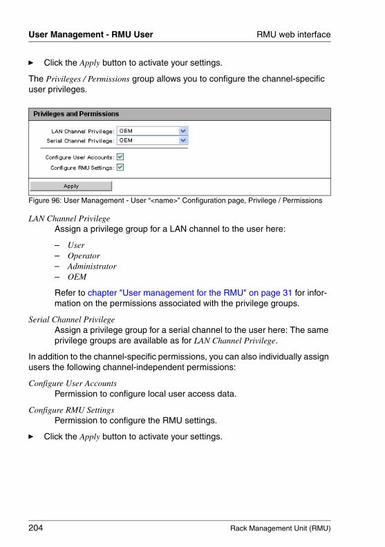
204 Rack Management Unit (RMU)
User Management - RMU User RMU web interface
© c
ogni
tas.
Ges
ells
chft
für
Tech
nik-
Dok
umen
tatio
n m
bH 2
009
Pfa
d: A
:\Ben
_Nev
is_R
MU
\Han
dbuc
h\en
\rm
u-en
.k05
Ê Click the Apply button to activate your settings.
The Privileges / Permissions group allows you to configure the channel-specific user privileges.
Figure 96: User Management - User “<name>” Configuration page, Privilege / Permissions
LAN Channel PrivilegeAssign a privilege group for a LAN channel to the user here:
– User– Operator– Administrator– OEM
Refer to chapter "User management for the RMU" on page 31 for infor-mation on the permissions associated with the privilege groups.
Serial Channel PrivilegeAssign a privilege group for a serial channel to the user here: The same privilege groups are available as for LAN Channel Privilege.
In addition to the channel-specific permissions, you can also individually assign users the following channel-independent permissions:
Configure User Accounts Permission to configure local user access data.
Configure RMU SettingsPermission to configure the RMU settings.
Ê Click the Apply button to activate your settings.
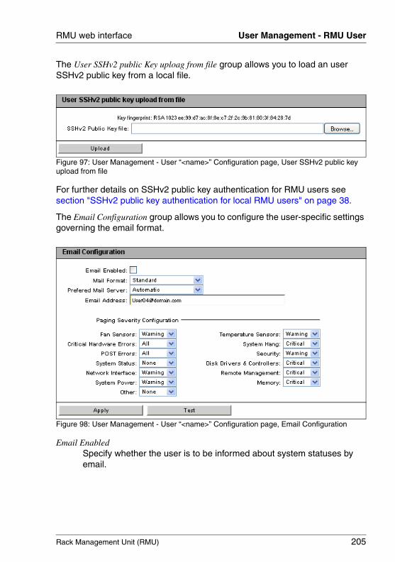
Rack Management Unit (RMU) 205
RMU web interface User Management - RMU User
The User SSHv2 public Key uploag from file group allows you to load an user SSHv2 public key from a local file.
Figure 97: User Management - User “<name>” Configuration page, User SSHv2 public key upload from file
For further details on SSHv2 public key authentication for RMU users see section "SSHv2 public key authentication for local RMU users" on page 38.
The Email Configuration group allows you to configure the user-specific settings governing the email format.
Figure 98: User Management - User “<name>” Configuration page, Email Configuration
Email EnabledSpecify whether the user is to be informed about system statuses by email.
206 Rack Management Unit (RMU)
User Management - RMU User RMU web interface
© c
ogni
tas.
Ges
ells
chft
für
Tech
nik-
Dok
umen
tatio
n m
bH 2
009
Pfa
d: A
:\Ben
_Nev
is_R
MU
\Han
dbuc
h\en
\rm
u-en
.k05
Mail FormatDepending on the selected email format, you can make a number of settings in the Email Alerting - Mail Format dependent Configuration group (see page 197).
The following email formats are available:
– Standard– Fixed Subject– ITS-Format– Fujitsu REMCS Format
Preferred Mail ServerSelect the preferred mail server.You can choose one of the following options:
– Automatic
If the email cannot be sent successfully immediately, for instance because the preferred mail server is not available, the email is sent to the second mail server.
– Primary
Only the mail server which has been configured as the primary SMTP server (see page 195) is used as the preferred mail server.
– Secondary
Only the mail server which has been configured as the secondary SMTP server (see page 196) is used as the preferred mail server.
I Errors sending email are recorded in the event log.
Email Address Email address of recipient.
Rack Management Unit (RMU) 207
RMU web interface User Management - RMU User
Paging Severity ConfigurationHere you can configure system events about which an RMU user is to be informed by email.
I Every entry in the event log for the RMU is assigned to a particular paging group.
The following settings are available for each event group:
NoneThe notification function is deactivated for this paging group.
CriticalThe RMU notifies users by email if an entry in the system event log is reported as CRITICAL.
WarningThe RMU notifies users by email if an entry in the system event log is reported as Minor or Major or Critical.
AllThe RMU notifies users of every event in this group which causes an entry to be made in the system event log.
Ê Click the Test button to test your settings.
Ê Click the Apply button to activate your settings.
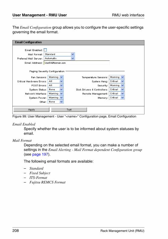
208 Rack Management Unit (RMU)
User Management - RMU User RMU web interface
© c
ogni
tas.
Ges
ells
chft
für
Tech
nik-
Dok
umen
tatio
n m
bH 2
009
Pfa
d: A
:\Ben
_Nev
is_R
MU
\Han
dbuc
h\en
\rm
u-en
.k05
The Email Configuration group allows you to configure the user-specific settings governing the email format.
Figure 99: User Management - User “<name>” Configuration page, Email Configuration
Email EnabledSpecify whether the user is to be informed about system statuses by email.
Mail FormatDepending on the selected email format, you can make a number of settings in the Email Alerting - Mail Format dependent Configuration group (see page 197).
The following email formats are available:
– Standard– Fixed Subject– ITS-Format– Fujitsu REMCS Format
Rack Management Unit (RMU) 209
RMU web interface User Management - RMU User
Preferred Mail ServerSelect the preferred mail server.You can choose one of the following options:
– Automatic
If the email cannot be sent successfully immediately, for instance because the preferred mail server is not available, the email is sent to the second mail server.
– Primary
Only the mail server which has been configured as the primary SMTP server (see page 195) is used as the preferred mail server.
– Secondary
Only the mail server which has been configured as the secondary SMTP server (see page 196) is used as the preferred mail server.
I Errors sending email are recorded in the event log.
Email Address Email address of recipient.
210 Rack Management Unit (RMU)
User Management - RMU User RMU web interface
© c
ogni
tas.
Ges
ells
chft
für
Tech
nik-
Dok
umen
tatio
n m
bH 2
009
Pfa
d: A
:\Ben
_Nev
is_R
MU
\Han
dbuc
h\en
\rm
u-en
.k05
Paging Severity ConfigurationHere you can configure system events about which an RMU user is to be informed by email.
I Every entry in the event log for the RMU is assigned to a particular paging group.
The following settings are available for each event group:
NoneThe notification function is deactivated for this paging group.
CriticalThe RMU notifies users by email if an entry in the system event log is reported as CRITICAL.
WarningThe RMU notifies users by email if an entry in the system event log is reported as Minor or Major or Critical.
AllThe RMU notifies users of every event in this group which causes an entry to be made in the system event log.
Ê Click the Apply button to activate your settings.
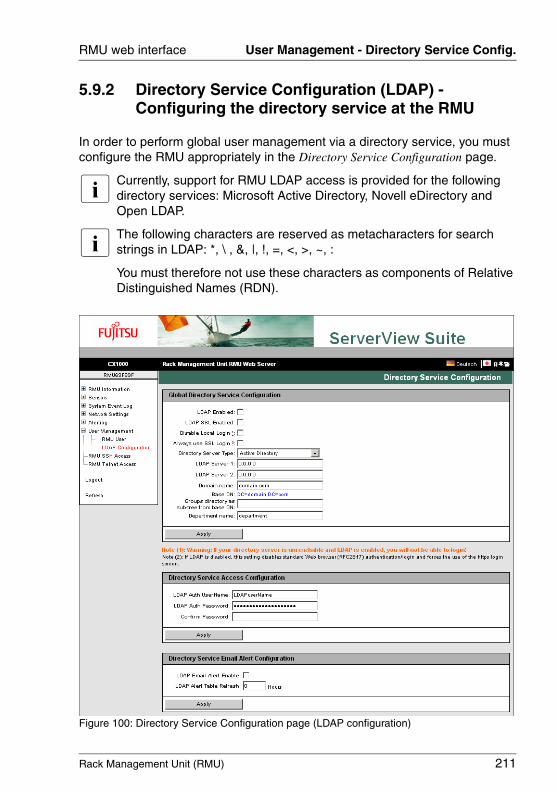
Rack Management Unit (RMU) 211
RMU web interface User Management - Directory Service Config.
5.9.2 Directory Service Configuration (LDAP) - Configuring the directory service at the RMU
In order to perform global user management via a directory service, you must configure the RMU appropriately in the Directory Service Configuration page.
I Currently, support for RMU LDAP access is provided for the following directory services: Microsoft Active Directory, Novell eDirectory and Open LDAP.
I The following characters are reserved as metacharacters for search strings in LDAP: *, \ , &, |, !, =, <, >, ~, :
You must therefore not use these characters as components of Relative Distinguished Names (RDN).
Figure 100: Directory Service Configuration page (LDAP configuration)
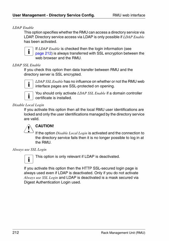
212 Rack Management Unit (RMU)
User Management - Directory Service Config. RMU web interface
© c
ogni
tas.
Ges
ells
chft
für
Tech
nik-
Dok
umen
tatio
n m
bH 2
009
Pfa
d: A
:\Ben
_Nev
is_R
MU
\Han
dbuc
h\en
\rm
u-en
.k05
LDAP EnableThis option specifies whether the RMU can access a directory service via LDAP. Directory service access via LDAP is only possible if LDAP Enable has been activated.
I If LDAP Enable is checked then the login information (see page 212) is always transferred with SSL encryption between the web browser and the RMU.
LDAP SSL EnableIf you check this option then data transfer between RMU and the directory server is SSL encrypted.
I LDAP SSL Enable has no influence on whether or not the RMU web interface pages are SSL-protected on opening.
I You should only activate LDAP SSL Enable if a domain controller certificate is installed.
Disable Local LoginIf you activate this option then all the local RMU user identifications are locked and only the user identifications managed by the directory service are valid.
V CAUTION!
If the option Disable Local Login is activated and the connection to the directory service fails then it is no longer possible to log in at the RMU.
Always use SSL Login
I This option is only relevant if LDAP is deactivated.
If you activate this option then the HTTP SSL-secured login page is always used even if LDAP is deactivated. Only if you do not activate Always use SSL Login and LDAP is deactivated is a mask secured via Digest Authentication Login used.
Rack Management Unit (RMU) 213
RMU web interface User Management - Directory Service Config.
Directory Server TypeType of directory server used:
The following directory services are supported:
– Active Directory: Microsoft Active Directory
– Novell: Novell eDirectory
– OpenLDAP: OpenLDAP
Ê Click the Apply button to activate your settings.
Different input fields are provided, depending on the directory service you select:
– For Active Directory, refer to "Configuring the RMU for Microsoft Active Directory" on page 214.
– For eDirectory and Open LDAP, refer to "Configuring RMU for Novell eDirectory / OpenLDAP" on page 218.
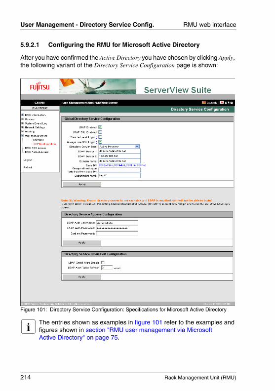
214 Rack Management Unit (RMU)
User Management - Directory Service Config. RMU web interface
© c
ogni
tas.
Ges
ells
chft
für
Tech
nik-
Dok
umen
tatio
n m
bH 2
009
Pfa
d: A
:\Ben
_Nev
is_R
MU
\Han
dbuc
h\en
\rm
u-en
.k05
5.9.2.1 Configuring the RMU for Microsoft Active Directory
After you have confirmed the Active Directory you have chosen by clicking Apply, the following variant of the Directory Service Configuration page is shown:
Figure 101: Directory Service Configuration: Specifications for Microsoft Active Directory
I The entries shown as examples in figure 101 refer to the examples and figures shown in section "RMU user management via Microsoft Active Directory" on page 75.
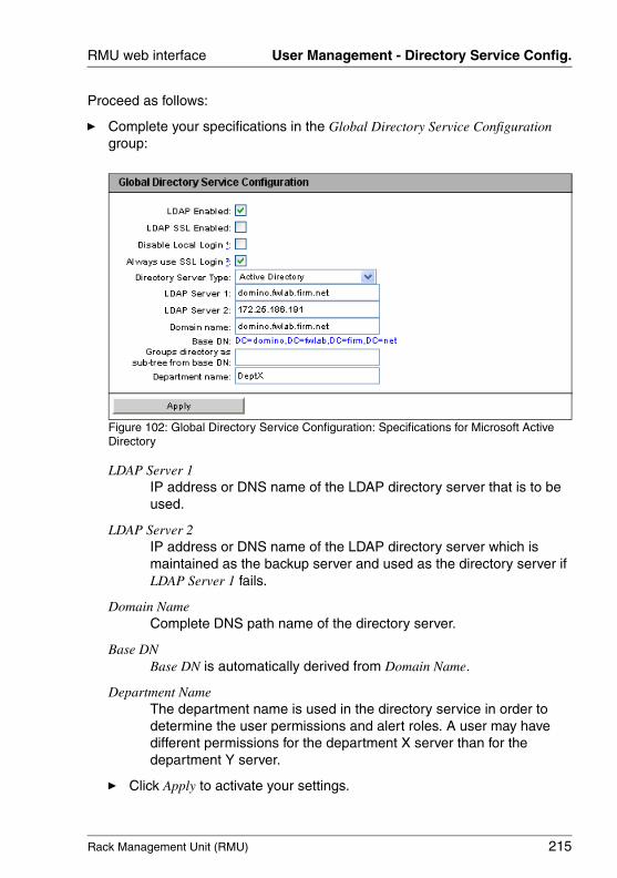
Rack Management Unit (RMU) 215
RMU web interface User Management - Directory Service Config.
Proceed as follows:
Ê Complete your specifications in the Global Directory Service Configuration group:
Figure 102: Global Directory Service Configuration: Specifications for Microsoft Active Directory
LDAP Server 1IP address or DNS name of the LDAP directory server that is to be used.
LDAP Server 2IP address or DNS name of the LDAP directory server which is maintained as the backup server and used as the directory server if LDAP Server 1 fails.
Domain NameComplete DNS path name of the directory server.
Base DNBase DN is automatically derived from Domain Name.
Department Name The department name is used in the directory service in order to determine the user permissions and alert roles. A user may have different permissions for the department X server than for the department Y server.
Ê Click Apply to activate your settings.
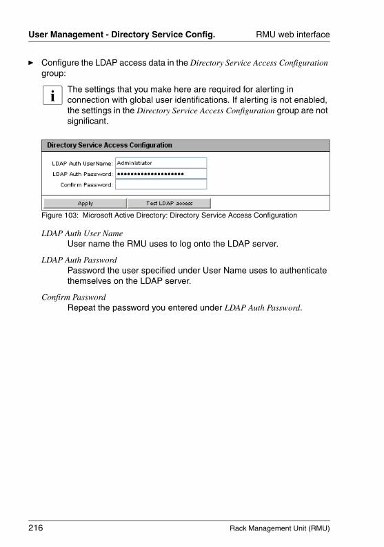
216 Rack Management Unit (RMU)
User Management - Directory Service Config. RMU web interface
© c
ogni
tas.
Ges
ells
chft
für
Tech
nik-
Dok
umen
tatio
n m
bH 2
009
Pfa
d: A
:\Ben
_Nev
is_R
MU
\Han
dbuc
h\en
\rm
u-en
.k05
Ê Configure the LDAP access data in the Directory Service Access Configuration group:
I The settings that you make here are required for alerting in connection with global user identifications. If alerting is not enabled, the settings in the Directory Service Access Configuration group are not significant.
Figure 103: Microsoft Active Directory: Directory Service Access Configuration
LDAP Auth User NameUser name the RMU uses to log onto the LDAP server.
LDAP Auth PasswordPassword the user specified under User Name uses to authenticate themselves on the LDAP server.
Confirm PasswordRepeat the password you entered under LDAP Auth Password.
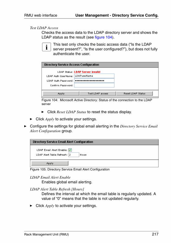
Rack Management Unit (RMU) 217
RMU web interface User Management - Directory Service Config.
Test LDAP AccessChecks the access data to the LDAP directory server and shows the LDAP status as the result (see figure 104).
I This test only checks the basic access data (“Is the LDAP server present?”, “Is the user configured?”), but does not fully authenticate the user.
Figure 104: Microsoft Active Directory: Status of the connection to the LDAP server
Ê Click Reset LDAP Status to reset the status display.
Ê Click Apply to activate your settings.
Ê Configure the settings for global email alerting in the Directory Service Email Alert Configuration group.
Figure 105: Directory Service Email Alert Configuration
LDAP Email Alert EnableEnables global email alerting.
LDAP Alert Table Refresh [Hours]Defines the interval at which the email table is regularly updated. A value of “0” means that the table is not updated regularly.
Ê Click Apply to activate your settings.
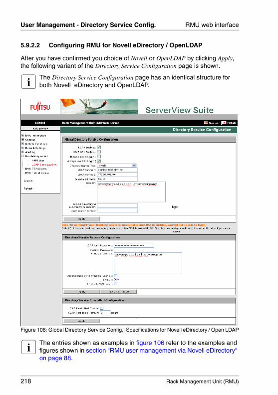
218 Rack Management Unit (RMU)
User Management - Directory Service Config. RMU web interface
© c
ogni
tas.
Ges
ells
chft
für
Tech
nik-
Dok
umen
tatio
n m
bH 2
009
Pfa
d: A
:\Ben
_Nev
is_R
MU
\Han
dbuc
h\en
\rm
u-en
.k05
5.9.2.2 Configuring RMU for Novell eDirectory / OpenLDAP
After you have confirmed you choice of Novell or OpenLDAP by clicking Apply, the following variant of the Directory Service Configuration page is shown.
I The Directory Service Configuration page has an identical structure for both Novell eDirectory and OpenLDAP.
Figure 106: Global Directory Service Config.: Specifications for Novell eDirectory / Open LDAP
I The entries shown as examples in figure 106 refer to the examples and figures shown in section "RMU user management via Novell eDirectory" on page 88.
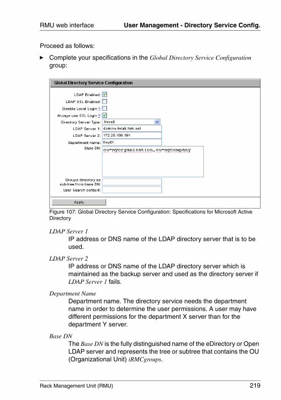
Rack Management Unit (RMU) 219
RMU web interface User Management - Directory Service Config.
Proceed as follows:
Ê Complete your specifications in the Global Directory Service Configuration group:
Figure 107: Global Directory Service Configuration: Specifications for Microsoft Active Directory
LDAP Server 1IP address or DNS name of the LDAP directory server that is to be used.
LDAP Server 2IP address or DNS name of the LDAP directory server which is maintained as the backup server and used as the directory server if LDAP Server 1 fails.
Department Name Department name. The directory service needs the department name in order to determine the user permissions. A user may have different permissions for the department X server than for the department Y server.
Base DNThe Base DN is the fully distinguished name of the eDirectory or Open LDAP server and represents the tree or subtree that contains the OU (Organizational Unit) iRMCgroups.
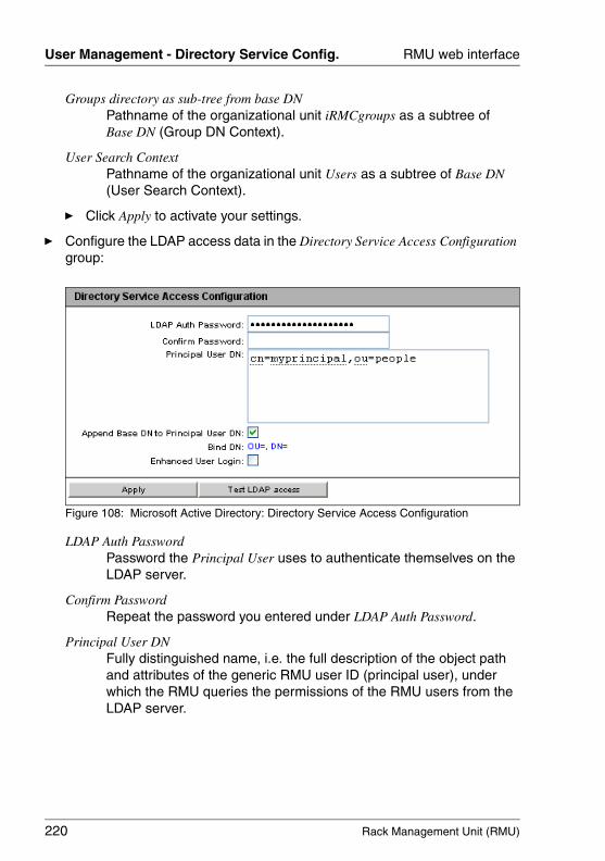
220 Rack Management Unit (RMU)
User Management - Directory Service Config. RMU web interface
© c
ogni
tas.
Ges
ells
chft
für
Tech
nik-
Dok
umen
tatio
n m
bH 2
009
Pfa
d: A
:\Ben
_Nev
is_R
MU
\Han
dbuc
h\en
\rm
u-en
.k05
Groups directory as sub-tree from base DNPathname of the organizational unit iRMCgroups as a subtree of Base DN (Group DN Context).
User Search ContextPathname of the organizational unit Users as a subtree of Base DN (User Search Context).
Ê Click Apply to activate your settings.
Ê Configure the LDAP access data in the Directory Service Access Configuration group:
Figure 108: Microsoft Active Directory: Directory Service Access Configuration
LDAP Auth PasswordPassword the Principal User uses to authenticate themselves on the LDAP server.
Confirm PasswordRepeat the password you entered under LDAP Auth Password.
Principal User DNFully distinguished name, i.e. the full description of the object path and attributes of the generic RMU user ID (principal user), under which the RMU queries the permissions of the RMU users from the LDAP server.
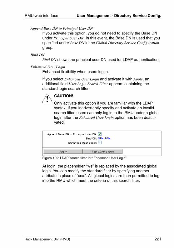
Rack Management Unit (RMU) 221
RMU web interface User Management - Directory Service Config.
Append Base DN to Principal User DNIf you activate this option, you do not need to specify the Base DN under Principal User DN. In this event, the Base DN is used that you specified under Base DN in the Global Directory Service Configuration group.
Bind DNBind DN shows the principal user DN used for LDAP authentication.
Enhanced User LoginEnhanced flexibility when users log in.
If you select Enhanced User Login and activate it with Apply, an additional field User Login Search Filter appears containing the standard login search filter.
V CAUTION!
Only activate this option if you are familiar with the LDAP syntax. If you inadvertently specify and activate an invalid search filter, users can only log in to the RMU under a global login after the Enhanced User Login option has been deacti-vated.
Figure 109: LDAP search filter for “Enhanced User Login”
At login, the placeholder “%s” is replaced by the associated global login. You can modify the standard filter by specifying another attribute in place of “cn=”. All global logins are then permitted to log into the RMU which meet the criteria of this search filter.
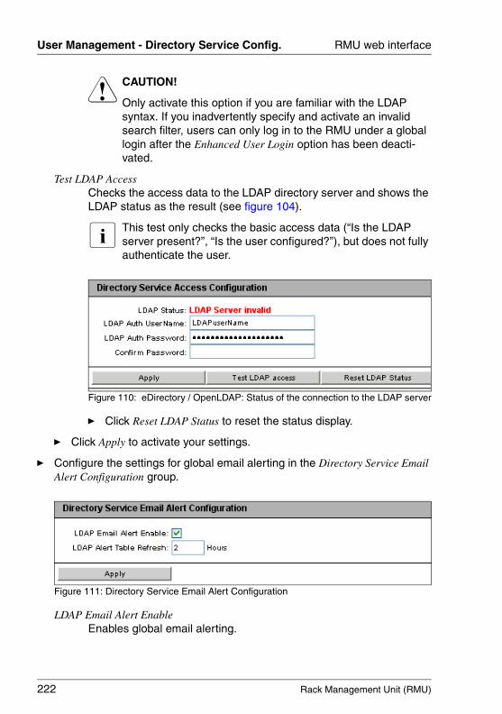
222 Rack Management Unit (RMU)
User Management - Directory Service Config. RMU web interface
© c
ogni
tas.
Ges
ells
chft
für
Tech
nik-
Dok
umen
tatio
n m
bH 2
009
Pfa
d: A
:\Ben
_Nev
is_R
MU
\Han
dbuc
h\en
\rm
u-en
.k05
V CAUTION!
Only activate this option if you are familiar with the LDAP syntax. If you inadvertently specify and activate an invalid search filter, users can only log in to the RMU under a global login after the Enhanced User Login option has been deacti-vated.
Test LDAP AccessChecks the access data to the LDAP directory server and shows the LDAP status as the result (see figure 104).
I This test only checks the basic access data (“Is the LDAP server present?”, “Is the user configured?”), but does not fully authenticate the user.
Figure 110: eDirectory / OpenLDAP: Status of the connection to the LDAP server
Ê Click Reset LDAP Status to reset the status display.
Ê Click Apply to activate your settings.
Ê Configure the settings for global email alerting in the Directory Service Email Alert Configuration group.
Figure 111: Directory Service Email Alert Configuration
LDAP Email Alert EnableEnables global email alerting.
Rack Management Unit (RMU) 223
RMU web interface User Management - Directory Service Config.
LDAP Alert Table Refresh [Hours]Defines the interval at which the email table is regularly updated. A value of “0” means that the table is not updated regularly.
Ê Click Apply to activate your settings.
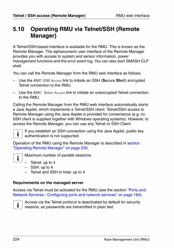
224 Rack Management Unit (RMU)
Telnet / SSH access (Remote Manager) RMU web interface
© c
ogni
tas.
Ges
ells
chft
für
Tech
nik-
Dok
umen
tatio
n m
bH 2
009
Pfa
d: A
:\Ben
_Nev
is_R
MU
\Han
dbuc
h\en
\rm
u-en
.k05
5.10 Operating RMU via Telnet/SSH (Remote Manager)
A Telnet/SSH-based interface is available for the RMU. This is known as the Remote Manager. The alphanumeric user interface of the Remote Manager provides you with access to system and sensor information, power management functions and the error event log. You can also start SMASH CLP shell.
You can call the Remote Manager from the RMU web interface as follows:
– Use the RMU SSH Access link to initiate an SSH (Secure Shell) encrypted Telnet connection to the RMU.
– Use the RMU Telnet Access link to initiate an unencrypted Telnet connection to the RMU.
Calling the Remote Manager from the RMU web interface automatically starts a Java Applet, which implements a Telnet/SSH client. Telnet/SSH access to Remote Manager using the Java Applet is provided for convenience (e.g. no SSH client is supplied together with Windows operating systems). However, to access the Remote Manager, you can use any Telnet or SSH Client.
I If you establish an SSH connection using the Java Applet, public key authentication is not supported.
Operation of the RMU using the Remote Manager is described in section "Operating Remote Manager" on page 230.
I Maximum number of parallel sessions:
– Telnet: up to 4 – SSH: up to 4– Telnet and SSH in total: up to 4
Requirements on the managed server
Access via Telnet must be activated for the RMU (see the section "Ports and Network Services - Configuring ports and network services" on page 184).
I Access via the Telnet protocol is deactivated by default for security reasons, as passwords are transmitted in plain text.

Rack Management Unit (RMU) 225
RMU web interface Telnet / SSH access (Remote Manager)
Establishing an SSH/Telnet connection and logging into the Remote Manager
I If the screen displays for SSH and Telnet connections differ only with respect to the connection-specific information displayed, the display for an SSH connection is shown below.
Ê In the navigation bar, click on the link RMU SSH Access (SSH) or RMU Telnet Access (Telnet).
The Java Applet for the SSH or Telnet connection is started and the following window is displayed (in this case using the example of an SSH connection):
Figure 112: Establishing an SSH connection to the RMU

226 Rack Management Unit (RMU)
Telnet / SSH access (Remote Manager) RMU web interface
© c
ogni
tas.
Ges
ells
chft
für
Tech
nik-
Dok
umen
tatio
n m
bH 2
009
Pfa
d: A
:\Ben
_Nev
is_R
MU
\Han
dbuc
h\en
\rm
u-en
.k05
Ê In the connection bar, click Connect.
As soon as the connection to the RMU has been established, you are requested to enter the user name and password.
– Logging into the Remote Manager over an SSH connection
I If the host key of the managed server is not yet registered at the remote workstation, the SSH client issues a security alert with suggestions on how to proceed.
The following login window is displayed:
Figure 113: SSH connection: Logging in to the Remote Manager
Ê Enter your user name and password and confirm your entries by clicking Login.
The main menu of the Remote Manager is then displayed (see figure 115 on page 228).
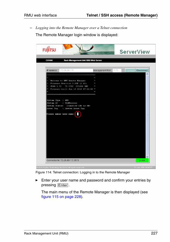
Rack Management Unit (RMU) 227
RMU web interface Telnet / SSH access (Remote Manager)
– Logging into the Remote Manager over a Telnet connection
The Remote Manager login window is displayed:
Figure 114: Telnet connection: Logging in to the Remote Manager
Ê Enter your user name and password and confirm your entries by pressing [Enter].
The main menu of the Remote Manager is then displayed (see figure 115 on page 228).
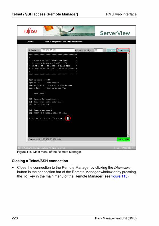
228 Rack Management Unit (RMU)
Telnet / SSH access (Remote Manager) RMU web interface
© c
ogni
tas.
Ges
ells
chft
für
Tech
nik-
Dok
umen
tatio
n m
bH 2
009
Pfa
d: A
:\Ben
_Nev
is_R
MU
\Han
dbuc
h\en
\rm
u-en
.k05
Figure 115: Main menu of the Remote Manager
Closing a Telnet/SSH connection
Ê Close the connection to the Remote Manager by clicking the Disconnect button in the connection bar of the Remote Manager window or by pressing the [0] key in the main menu of the Remote Manager (see figure 115).
Rack Management Unit (RMU) 229
6 RMU serial port interface (Remote Manager)
A Telnet-based interface is available for the RMU. This is known as the Remote Manager. You can call the Remote Manager over the following interfaces:
– RMU web interface (see page 135)– any Telnet/SSH client
The RMU supports secure connections over SSH (Secure Shell). The Remote Manager interface is identical for Telnet and SSH connections. Any Telnet/SSH client that interprets VT100 sequences can be used to access the RMU. It is nevertheless recommended that the RMU web interface be used.
I Maximum number of parallel sessions:
– Telnet: up to 4 – SSH: up to 4– Telnet and SSH in total: up to 4
Requirements on the managed server
Access via Telnet must be activated for the RMU (see the section section "Ports and Network Services - Configuring ports and network services" on page 184).
I Access via the Telnet protocol is deactivated by default for security reasons, as passwords are transmitted in plain text.
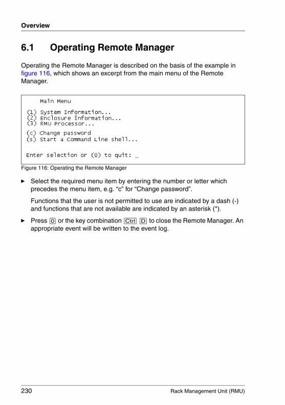
230 Rack Management Unit (RMU)
Overview
© c
ogni
tas.
Ges
ells
chft
für
Tech
nik-
Dok
umen
tatio
n m
bH 2
009
Pfa
d: A
:\Ben
_Nev
is_R
MU
\Han
dbuc
h\en
\rm
u-en
.k06
6.1 Operating Remote Manager
Operating the Remote Manager is described on the basis of the example in figure 116, which shows an excerpt from the main menu of the Remote Manager.
Figure 116: Operating the Remote Manager
Ê Select the required menu item by entering the number or letter which precedes the menu item, e.g. “c” for “Change password”.
Functions that the user is not permitted to use are indicated by a dash (-) and functions that are not available are indicated by an asterisk (*).
Ê Press [0] or the key combination [Ctrl] [D] to close the Remote Manager. An appropriate event will be written to the event log.

Rack Management Unit (RMU) 231
Telnet/SSH - Remote Manager Overview of menus
6.2 Overview of menus
The Remote Manager menu for the RMU has the following structure:
● System Information
– Chassis Information
– Mainboard Information
● Enclosure Information
– System Event-Log
– View System Event-Log (text, newest first)
– View System Event-Log (text, oldest first)
– Dump System Event-Log (raw, newest first)
– Dump System Event-Log (raw, oldest first)
– View System Eventlog Information
– Clear System Event-Log
– Temperature
– Voltages
– Fans
– Pressure
– Contact/Switch
– Component Status
– List All Sensors
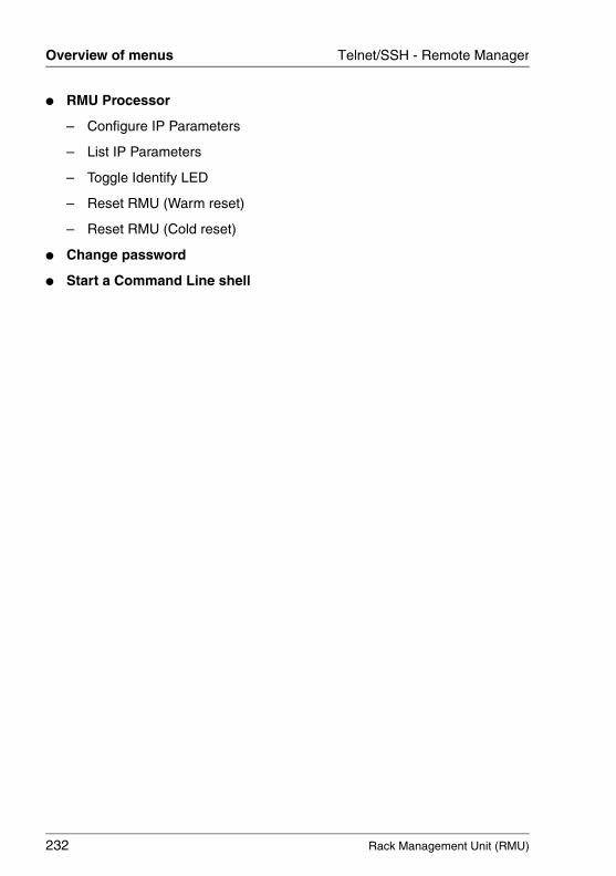
232 Rack Management Unit (RMU)
Overview of menus Telnet/SSH - Remote Manager
© c
ogni
tas.
Ges
ells
chft
für
Tech
nik-
Dok
umen
tatio
n m
bH 2
009
Pfa
d: A
:\Ben
_Nev
is_R
MU
\Han
dbuc
h\en
\rm
u-en
.k06
● RMU Processor
– Configure IP Parameters
– List IP Parameters
– Toggle Identify LED
– Reset RMU (Warm reset)
– Reset RMU (Cold reset)
● Change password
● Start a Command Line shell
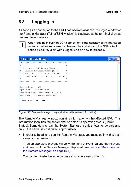
Rack Management Unit (RMU) 233
Telnet/SSH - Remote Manager Logging in
6.3 Logging in
As soon as a connection to the RMU has been established, the login window of the Remote Manager (Telnet/SSH window) is displayed at the terminal client at the remote workstation.
I When logging in over an SSH connection: If the host key of the managed server is not yet registered at the remote workstation, the SSH client issues a security alert with suggestions on how to proceed.
Figure 117: Remote Manager: Login window (with system information)
The Remote Manager window contains information on the affected RMU. This information identifies the server and indicates its operating status (Power Status). Some details (e.g. the System Name) are only shown for servers and only if the server is configured appropriately.
Ê In order to be able to use the Remote Manager, you must log in with a user name and a password.
Then an appropriate event will be written to the Event log and the relevant main menu of the Remote Manager displayed (see section "Main menu of the Remote Manager" on page 234).
You can terminate the login process at any time using [Ctrl][D].
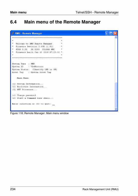
234 Rack Management Unit (RMU)
Main menu Telnet/SSH - Remote Manager
© c
ogni
tas.
Ges
ells
chft
für
Tech
nik-
Dok
umen
tatio
n m
bH 2
009
Pfa
d: A
:\Ben
_Nev
is_R
MU
\Han
dbuc
h\en
\rm
u-en
.k06
6.4 Main menu of the Remote Manager
Figure 118: Remote Manager: Main menu window
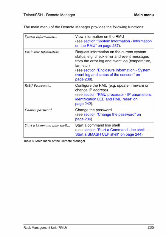
Rack Management Unit (RMU) 235
Telnet/SSH - Remote Manager Main menu
The main menu of the Remote Manager provides the following functions:
System Information... View information on the RMU(see section "System Information - Information on the RMU" on page 237).
Enclosure Information... Request information on the current system status, e.g. check error and event messages from the error log and event log (temperature, fan, etc.)(see section "Enclosure Information - System event log and status of the sensors" on page 238).
RMU Processor... Configure the RMU (e.g. update firmware or change IP address)(see section "RMU processor - IP parameters, identification LED and RMU reset" on page 242).
Change password Change the password(see section "Change the password" on page 236).
Start a Command Line shell... Start a command line shell (see section "Start a Command Line shell... - Start a SMASH CLP shell" on page 244).
Table 8: Main menu of the Remote Manager
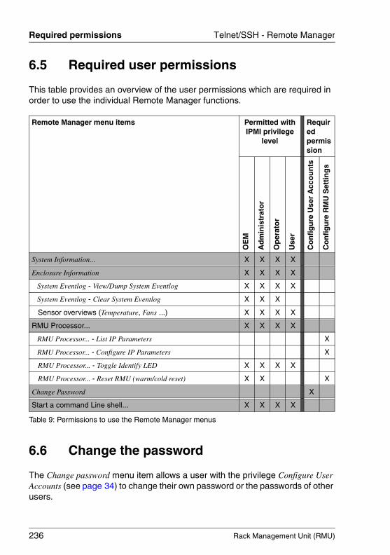
236 Rack Management Unit (RMU)
Required permissions Telnet/SSH - Remote Manager
© c
ogni
tas.
Ges
ells
chft
für
Tech
nik-
Dok
umen
tatio
n m
bH 2
009
Pfa
d: A
:\Ben
_Nev
is_R
MU
\Han
dbuc
h\en
\rm
u-en
.k06
6.5 Required user permissions
This table provides an overview of the user permissions which are required in order to use the individual Remote Manager functions.
6.6 Change the password
The Change password menu item allows a user with the privilege Configure User Accounts (see page 34) to change their own password or the passwords of other users.
Remote Manager menu items Permitted withIPMI privilege
level
Required permission
OE
M
Ad
min
istr
ato
r
Op
erat
or
Use
r
Co
nfi
gu
re U
ser
Acc
ou
nts
Co
nfi
gu
re R
MU
Set
tin
gs
System Information... X X X X
Enclosure Information X X X X
System Eventlog - View/Dump System Eventlog X X X X
System Eventlog - Clear System Eventlog X X X
Sensor overviews (Temperature, Fans ...) X X X X
RMU Processor... X X X X
RMU Processor... - List IP Parameters X
RMU Processor... - Configure IP Parameters X
RMU Processor... - Toggle Identify LED X X X X
RMU Processor... - Reset RMU (warm/cold reset) X X X
Change Password X
Start a command Line shell... X X X X
Table 9: Permissions to use the Remote Manager menus

Rack Management Unit (RMU) 237
Telnet/SSH - Remote Manager System Information
6.7 System Information - Information on the RMU
The following menu appears if you choose System Information... from the main menu:
Figure 119: Remote Manager: System Information window
The submenu contains the following functions:
Chassis Information Information on the chassis of the RMU and its product data.
Mainboard Information Information on the mainboard of the RMU and its product data.
Table 10: System Information menu
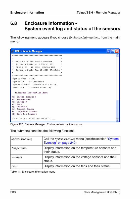
238 Rack Management Unit (RMU)
Enclosure Information Telnet/SSH - Remote Manager
© c
ogni
tas.
Ges
ells
chft
für
Tech
nik-
Dok
umen
tatio
n m
bH 2
009
Pfa
d: A
:\Ben
_Nev
is_R
MU
\Han
dbuc
h\en
\rm
u-en
.k06
6.8 Enclosure Information - System event log and status of the sensors
The following menu appears if you choose Enclosure Information... from the main menu:
Figure 120: Remote Manager: Enclosure Information window
The submenu contains the following functions:
System Eventlog Call the System Eventlog menu (see the section "System Eventlog" on page 240).
Temperature Display information on the temperature sensors and their status.
Voltages Display information on the voltage sensors and their status.
Fans Display information on the fans and their status.
Table 11: Enclosure Information menu
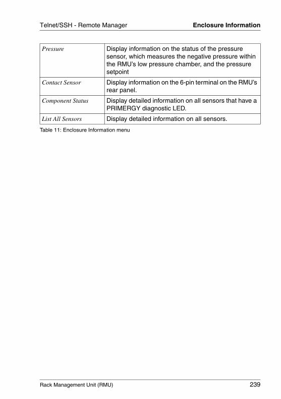
Rack Management Unit (RMU) 239
Telnet/SSH - Remote Manager Enclosure Information
Pressure Display information on the status of the pressure sensor, which measures the negative pressure within the RMU’s low pressure chamber, and the pressure setpoint
Contact Sensor Display information on the 6-pin terminal on the RMU’s rear panel.
Component Status Display detailed information on all sensors that have a PRIMERGY diagnostic LED.
List All Sensors Display detailed information on all sensors.
Table 11: Enclosure Information menu
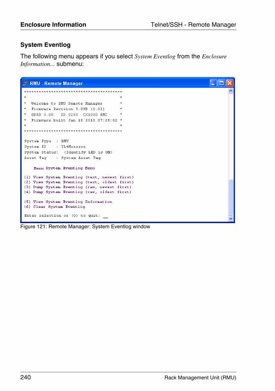
240 Rack Management Unit (RMU)
Enclosure Information Telnet/SSH - Remote Manager
© c
ogni
tas.
Ges
ells
chft
für
Tech
nik-
Dok
umen
tatio
n m
bH 2
009
Pfa
d: A
:\Ben
_Nev
is_R
MU
\Han
dbuc
h\en
\rm
u-en
.k06
System Eventlog
The following menu appears if you select System Eventlog from the Enclosure Information... submenu:
Figure 121: Remote Manager: System Eventlog window
Rack Management Unit (RMU) 241
Telnet/SSH - Remote Manager Enclosure Information
The submenu contains the following functions:
View System Eventlog (text, newest first)
The contents of the Event log are output to screen in a readable form and in chronological order (the most recent entry first).
View System Eventlog (text, oldest first)
The contents of the Event log are output to screen in a readable form and in reverse chronological order (the oldest entry first).
Dump System Eventlog (raw, newest first)
The contents of the Event log are dumped in chrono-logical order (the most recent entry first).
Dump System Eventlog (raw, oldest first)
The contents of the Event log are dumped in reverse chronological order (the oldest entry first).
View System Eventlog Information
Display information on the event log.
Clear System Eventlog Clear the contents of the event log.
Table 12: System Eventlog menu
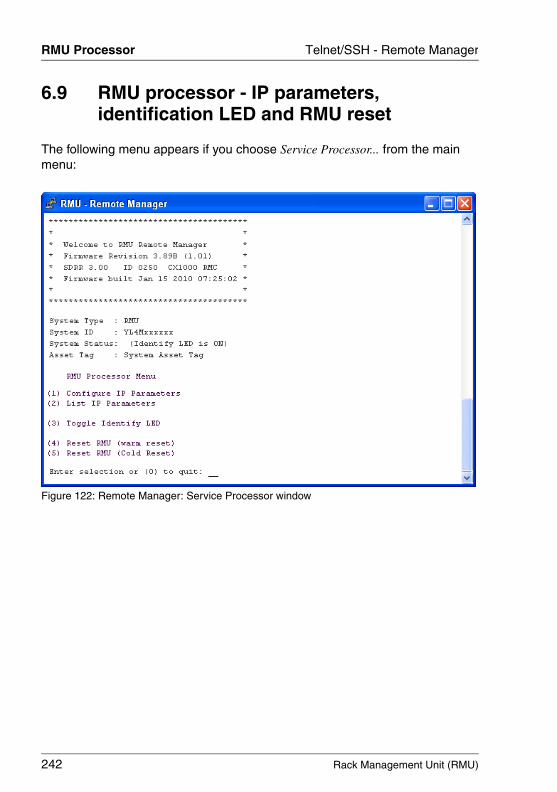
242 Rack Management Unit (RMU)
RMU Processor Telnet/SSH - Remote Manager
© c
ogni
tas.
Ges
ells
chft
für
Tech
nik-
Dok
umen
tatio
n m
bH 2
009
Pfa
d: A
:\Ben
_Nev
is_R
MU
\Han
dbuc
h\en
\rm
u-en
.k06
6.9 RMU processor - IP parameters, identification LED and RMU reset
The following menu appears if you choose Service Processor... from the main menu:
Figure 122: Remote Manager: Service Processor window
Rack Management Unit (RMU) 243
Telnet/SSH - Remote Manager RMU Processor
The submenu contains the following functions:
I It is recommended that you reboot the server after a Reset RMU (Cold Reset) or Reset RMU (Warm Reset).
Configure IP Parameters Configure the IP address, subnet mask and default gateway. You can also specify whether DHCP is to be activated
List IP Parameters Display the IP settings.
Toggle Identify LED Switch the identification LED on/off.
Reset RMU (warm reset) Reset the RMU. The connection is closed. Only the interfaces are re-initialized.
Reset RMU (cold reset) Reset the RMU. The connection is closed. The entire RMU is re-initialized.
Table 13: Service Processor menu
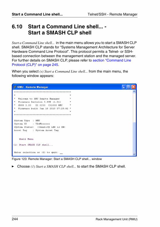
244 Rack Management Unit (RMU)
Start a Command Line shell... Telnet/SSH - Remote Manager
© c
ogni
tas.
Ges
ells
chft
für
Tech
nik-
Dok
umen
tatio
n m
bH 2
009
Pfa
d: A
:\Ben
_Nev
is_R
MU
\Han
dbuc
h\en
\rm
u-en
.k06
6.10 Start a Command Line shell... - Start a SMASH CLP shell
Start a Command Line shell... in the main menu allows you to start a SMASH CLP shell. SMASH CLP stands for “Systems Management Architecture for Server Hardware Command Line Protocol”. This protocol permits a Telnet- or SSH-based connection between the management station and the managed server. For further details on SMASH CLP, please refer to section "Command Line Protocol (CLP)" on page 245.
When you select (s) Start a Command Line shell... from the main menu, the following window appears:
Figure 123: Remote Manager: Start a SMASH CLP shell... window
Ê Choose (1) Start a SMASH CLP shell... to start the SMASH CLP shell.
Rack Management Unit (RMU) 245
Telnet/SSH - Remote Manager Command Line Protocol (CLP)
6.11 Command Line Protocol (CLP)
The RMU supports various text-based user interfaces, known as user shells, which can be configured differently for individual users.
The Systems Management Architecture for Server Hardware (SMASH) initiative defines a number of specifications with the following objectives:
– Provision of standardized interfaces for managing heterogeneous computer environments,
– Provision of an architecture framework with uniform interfaces, hardware and software discovery, resource addressing and data models.
You can find further information on SMASH under the following link:
http://www.dmtf.org/standards/smash
SMASH CLP syntax
SMASH CLP specifies a common command line syntax and message protocol semantics for managing computers on the Internet and in enterprise and service provider environments. You can find detailed information on SMASH CLP in the DMTF document “Server Management Command Line Protocol Specification (SM CLP) DSP0214”.
The general syntax of the CLP is as follows:
<verb> [<options>] [<target>] [<properties>]
<verb>Verbs specify the command or action to be executed. The list of verbs describes the following activities, for instance:
– Establish (set) and retrieve (show) data,
– Change the status of a target (reset, start, stop),
– Manage the current session (cd, version, exit),
– Return information on commands (help).
In RMU systems, the verb oemfujitsu also allows the use of special OEM commands.
246 Rack Management Unit (RMU)
Command Line Protocol (CLP) Telnet/SSH - Remote Manager
© c
ogni
tas.
Ges
ells
chft
für
Tech
nik-
Dok
umen
tatio
n m
bH 2
009
Pfa
d: A
:\Ben
_Nev
is_R
MU
\Han
dbuc
h\en
\rm
u-en
.k06
<options>Command options modify the action or the behavior of a verb. Options can immediately follow the verb in a command line and must always be introduced by a dash ("-").
Options allow you to, for instance,
– define the output format,
– permit recursive execution of a command,
– display the version of a command or
– request help.
<target><target> specifies the address or the path of the object to be manipulated by the command, i.e. the target of the command. This can be a single managed element such as a hard disk, a network adapter (Network Interface Card, NIC), or the management program (Management Assis-tance Program, MAP) itself. Targets can, however, also be services such as a transport service.
Several managed elements which can be managed by the management program can be subsumed under a single <target>, for instance the entire system.
Only one <target> may be specified for each command.
<properties><properties> describe the properties of the target of the command which are required to execute the command. Thus, <properties> identify the properties of the target’s class that are to be retrieved or modified by the command.
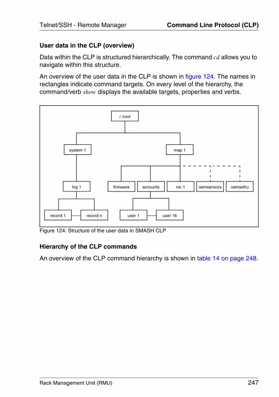
Rack Management Unit (RMU) 247
Telnet/SSH - Remote Manager Command Line Protocol (CLP)
User data in the CLP (overview)
Data within the CLP is structured hierarchically. The command cd allows you to navigate within this structure.
An overview of the user data in the CLP is shown in figure 124. The names in rectangles indicate command targets. On every level of the hierarchy, the command/verb show displays the available targets, properties and verbs.
Figure 124: Structure of the user data in SMASH CLP
Hierarchy of the CLP commands
An overview of the CLP command hierarchy is shown in table 14 on page 248.
record 1 record n
firmware accounts nic 1 oemsensors oemsefru
/./root
log 1
system 1
user 16
map 1
user 1
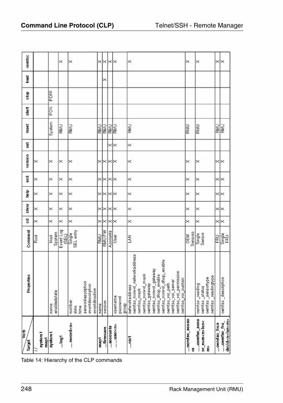
248 Rack Management Unit (RMU)
Command Line Protocol (CLP) Telnet/SSH - Remote Manager
© c
ogni
tas.
Ges
ells
chft
für
Tech
nik-
Dok
umen
tatio
n m
bH 2
009
Pfa
d: A
:\Ben
_Nev
is_R
MU
\Han
dbuc
h\en
\rm
u-en
.k06
Table 14: Hierarchy of the CLP commands
Rack Management Unit (RMU) 249
IndexAActive Directory 31, 51
configuration using the RMU web interface 214
RMU groups and user permissions 81
Active Session Information 150alert role
assigning users 131alert roles
displaying 129alert types 125alerting
configuring 191assign
RMU users to a group 81, 108
Bboot
RMU 150
CCA (Certification Authority) 76CA certificate
loading from local file 156CA DSA/RSA certificate
showing 154certificate
self-signed 159Certification Authority (CA) 76certification authority, see also CAchannel-specific
permission group 34privileges 34
checkpower supply 172pressure sensor 170see also enclosure
information 238sensors 166server component 173
temperature 238temperature sensor 168voltage sensor 169
CLP 245syntax 245user data 247
CLP, see also SMASH CLPcolor code (sensor) 166Command Line Protocol (CLP) 245command line shell (Remote
Manager) 244component status 173components (RMU)
monitoring 173configuration file
(SVS_LdapDeployer) 64configure
alerting 191directory service 211directory service
(eDirectory) 218directory service
(OpenLDAP) 218DNS for RMU 189eDirectory 96eDirectory for LDAP 97email alerting 193Ethernet settings (RMU) 181global email alerting 128host name for RMU 187LAN interface 180LDAP access on the RMU 76mail-format-dependent
settings 197new user 201OpenLDAP 116ports and network services
(RMU) 184SNMP trap alerting 192switches 171system event log (server) 178
250 Rack Management Unit (RMU)
Index
© c
ogni
tas.
Ges
ells
chft
für
Tech
nik-
Dok
umen
tatio
n m
bH 2
009
Pfa
d: A
:\Ben
_Nev
is_R
MU
\Han
dbuc
h\en
\rm
u-en
.six
user 201user (details) 202users 199users, locally 200
ConsoleOneinstalling 94starting 95
controlfan speed 26
copyright (SSL) 132create
NDS tree (eDirectory) 96SSH key pair 39
CSS LED 146
DDHCP configuration 187directory service 31, 51, 211
see also Active Directory, eDirectory, OpenLDAP
displayalert roles 129current DSA certificate 154permission groups 63user roles 62
DNS for RMUconfiguring 189
DNS settings 189Documentation 11domain controller 78domain controller certificate 78, 80DSA certificate
default certificate 152displaying current 154entering directly 158restoring default certificate 155
DSA key (private)entering directly 158loading on the RMU 152providing in file 157
DSA/RSA certificateentering directly 158input format 152loading on the RMU 152
showing 154DSA/RSA key
entering directly 158input format 152
EeDirectory 31, 51
administration tips 112assigning RMU users to the OU
iRMCgroups 108configuring 96configuring for LDAP 97creating Principal User for
RMU 104LDAP authentication
process 103RMU groups and user
permissions 104software components and system
requirements 88testing access via LDAP
browser 101eDirectory Server
installing 90email alerting
configuring 193global 124
enclosure information (Remote Manager) 238
enterDSA certificate 158DSA/RSA key 158
Enterprise CA 76Enterprise Certification authority, see
Enterprise CA 76error icon 174error list
error icon 174error log
error icon 174Ethernet 181Ethernet settings (RMU)
configuring 181
Rack Management Unit (RMU) 251
Index
Ffactory defaults, RMU 89Fan LED 146fan prefailure detection 29fan speed control 26fan speed monitoring 29, 167fan test 167fans, monitoring 167firmware image, RMU 20firmware selector, RMU 21firmware update
online update 161
Ggenerate
self-signed certificate 159global email alerting 124
configuring 128global email paging
configuration 194Global Error LED 145global RMU user ID 31global RMU user management 51
via Active Directory 75via eDirectory 88via OpenLDAP 115
GPIO monitoring 30, 171
Hhelpdesk information 179host name (RMU)
configuring 187see also RMU name
Iidentification LED 146, 242iManager
installing 92login 93
installConsoleOne 94eDirectory administration
utilities 90eDirectory Server 90
iManager 92OpenLDAP 115
iRMCgroups 64assigning RMU users
(eDirectory) 108
Kkonfigurieren
Directory Service (Active Directory) 214
LLAN interface (RMU)
configuring 180LDAP access (RMU)
configuring 76LDAP authentication process
(eDirectory) 103LDAP configuration 211
Active Directory 214eDirectory 218OpenLDAP 218
LDAP email table 126LDAP, see also directory servicelocal user ID (RMU) 31local user management (RMU) 200log in
to Remote Manager 233to the RMU web interface 136
Mmail-format-dependent
configuration 197main menu (Remote Manager) 234Microsoft Active Directory see Active
DirectoryMicrosoft Active Directory see also
Active Directorymonitor
fan speed 29, 167fans 167GPIO 30, 171power supply 172pressure 29, 170
252 Rack Management Unit (RMU)
Index
© c
ogni
tas.
Ges
ells
chft
für
Tech
nik-
Dok
umen
tatio
n m
bH 2
009
Pfa
d: A
:\Ben
_Nev
is_R
MU
\Han
dbuc
h\en
\rm
u-en
.six
temperature 30, 168voltage 29, 169
monitor, see also checkmonitoring functions (RMU) 29
Nnetwork interface 181network settings 180new user configuration 201notational conventions 12Novell ConsoleOne see also
ConsoleOneNovell eDirectory see eDirectoryNovell eDirectory Server see also
eDirectory ServerNovell iManager see also iManager
OOpen LDAP Browser/Editor 118OpenLDAP 31, 51
administration tips 122configuring 116creating an RMU user 120creating SSL certificates 115generating the Principal
User 119installing 115integrating RMU user
management 118RMU groups and user
permissions 118RMU user management 115
OpenSSH client 48operate
Remote Manager 230RMU via Telnet/SSH 224
organizational unitiRMCgroups 55, 59SVS 55, 61
Ppassword
changing 236
permission group 59channel-specific 34
permission groupsdisplaying 63
permission, see also privilegepermissions
for special RMU functions 34Remote Manager 236RMU web interface 138
ports and network services 184configuring for RMU 184
power supplymonitoring 172
preconfigured user ID 35pressure leakage status 30Pressure LED 146pressure monitoring 29, 170pressure profile 27pressure sensor
checking 170primary SMTP server
configuration 195Principal User
creating in eDirectory 104generating in OpenLDAP 119
private DSA/RSA key, see DSA/RSA key
privilegeprivileges / permissions 204privileges, channel-specific 34PuTTY 45PuTTYgen 39
Qquery
information on server 144RMU information 143, 149system information 237
query informationinformation on server 144on RMU 149power supply 172RMU firmware 150system event log 178
Rack Management Unit (RMU) 253
Index
voltage sensors 169querying
RMU firmware image information 162
querying informationRMU firmware 162
RRack Management Unit (RMU) 13Rack Management Unit see also RMURemote Manager 224
changing the password 236enclosure information 238logging in 233main menu 234operating 230permissions 236RMU processor 242starting the command line
shell 244system event log 240system information 237
RMUconfiguring the LAN
interface 180factory defaults 89fan speed control 26fan speed monitoring 29, 167firmware 19, 161firmware image 20firmware image information 162firmware selector 21front panel 15GPIO monitoring 30, 171hardware 14logging into the web
interface 136monitoring functions 29permissions 34pressure monitoring 29, 170pressure profile 27rack server management 25rear panel 18restarting 150
see also Rack Management UnitSSH key 43technical data 23temperature monitoring 30, 168user interface 140user management 31user permissions 34voltage monitoring 29, 169
RMU information 143, 149querying 143
RMU processor (Remote Manager) 242
RMU SSH access 224RMU Telnet access 224RMU time, adjust manually 151RMU user
assigning 81, 108creating in OpenLDAP 120
RMU user groupassigning 81, 108
RMU user managementglobal via Active Directory 75global via eDirectory 88global via OpenLDAP 115integrating in OpenLDAP 118
RMU web interface 135alerting 191alerting - email alerting 193alerting - SNMP trap alerting 192certificate upload 152DHCP configuration 187directory service
configuration 211DNS settings 189firmware update via TFTP 161network interface 181permissions 138ports and network services 184RMU information 143, 149RMU SSH access 224RMU Telnet access 224RMU Telnet/SSH access 224sensors 166sensors - component status 173

254 Rack Management Unit (RMU)
Index
© c
ogni
tas.
Ges
ells
chft
für
Tech
nik-
Dok
umen
tatio
n m
bH 2
009
Pfa
d: A
:\Ben
_Nev
is_R
MU
\Han
dbuc
h\en
\rm
u-en
.six
sensors - contact/switch configuration 171
sensors - fans 167sensors - power supply 172sensors - pressure 170sensors - temperature 168sensors - voltages 169structure of the user
interface 140system component
information 144system event log 174system event log
configuration 178system event log content 175user management 36, 199user management (local) 200user management - new user
configuration 201user management - user “name”
configuration 201, 202RSA certificate, see DSA/RSA
certificate
Ssecondary SMTP server
configuration 196security group 59security group, see also permission
groupself-signed certificate 159sensor
checking 166color code 166status icon 166
sensors 166server
checking components 173checking sensor 166configuring the event log 178view event log 177
showCA DSA/RSA certificate 154DSA/RSA certificate 154
SMASH CLP 245command hierarchy 247commands 245starting 244syntax 245user data 247
SNMP alerting, see SNMP trap alerting
SNMP trap alerting 192configuring 192
SSH 152, 224SSH key (example) 50SSH key (public)
loading onto the RMU 43SSHv2 public key 205SSHv2 public key support 38SSL 152SSL and SSH certificate 152SSL certificate
creating 115SSL copyright 132start
SVS_LdapDeployer 65status
components 173status icon (sensor) 166SVS 61, 64SVS_LdapDeployer 64
-delete 69-deploy 67-import 70-synchronize 71application scenarios 73configuration file 64starting 65
switch, configure 171system event log 174, 240
configuring 178information 176view 177
system event log configuration 178system event log content 175, 177system fans 167

Rack Management Unit (RMU) 255
Index
system information (Remote Manager) 237
system overview 144
Ttarget group 10Telnet 224temperature
monitoring 168temperature monitoring 30, 168temperature sensor
checking 168test, fan 167
Uuser
configuring 199, 201configuring (details) 202configuring (new) 201
user “name” configuration 202user ID 31
preconfigured 35user interface (RMU) 140user management 199user management (RMU) 31, 199,
200assigning users to a group 81,
108concept 32configuring LDAP access 76creating a domain controller
certificate 78generating iRMCgroups in the
LDAP directory service 64generating SVS in the LDAP
directory service 64global 51global user permissions 53, 57installing a domain controller
certificate 80installing an Enterprise CA 76integrating in eDirectory 102local using the RMU web
interface 200
local via the RMU web interface 36
preferred shell 61user ID 31using Active Directory 51, 53via directory service 53
user permissions 34cross-server 57global 53, 57in Active Directory 81in eDirectory 104in OpenLDAP 118
user rolesdisplaying 62
User SSHv2 public key upload from file 205
Vventilator, see also fanview, system event log (server) 177voltage monitoring 29, 169voltage sensor, checking 169
XX.509 certificate, see DSA/RSA
certificate

© c
ogni
tas.
Ges
ells
chft
für
Tech
nik-
Dok
umen
tatio
n m
bH 2
009
Pfa
d: A
:\Ben
_Nev
is_R
MU
\Han
dbuc
h\en
\rm
u-en
.six