Race Car Design Proj 2011
56
Engineering Design and Technology Series F1 in Schools TM Design Project with SolidWorks ® 2011 Software Dassault Systèmes SolidWorks Corp. 300 Baker Avenue Concord, MA 01742 USA Phone: 1 800 693 9000 Outside the US: 1 978 371 5011 Fax: 1 978 371 7303 [email protected] For Type-R Cars
-
Upload
jaydeepsinh -
Category
Documents
-
view
19 -
download
5
description
free
Transcript of Race Car Design Proj 2011
Engineering Designand Technology Series
F1 in SchoolsTM Design Project with SolidWorks® 2011 Software
Dassault Systèmes SolidWorks Corp.300 Baker AvenueConcord, MA 01742 USAPhone: 1 800 693 9000
Outside the US: 1 978 371 5011Fax: 1 978 371 7303
For Type-R Cars

© 1995-2011, Dassault Systèmes SolidWorks Corporation, a Dassault Systèmes S.A. company, 300 Baker AvenueConcord, Massachusetts 01742 USA. All Rights Reserved.
The information and the software discussed in this document are subject to change without notice and are not commitments by Dassault Systèmes SolidWorks Corporation (DS SolidWorks).No material may be reproduced or transmitted in any form or by any means, electronic or mechanical, for any purpose without the express written permission of DS SolidWorks.The software discussed in this document is furnished under a license and may be used or copied only in accordance with the terms of this license. All warranties given by DS SolidWorks as to the software and documentation are set forth in the SolidWorks Corporation License and Subscription Service Agreement, and nothing stated in, or implied by, this document or its contents shall be considered or deemed a modification or amendment of such warranties.
Patent Notices for SolidWorks Standard, Premium, and Professional Products.US Patents 5,815,154; 6,219,049; 6,219,055; 6,603,486; 6,611,725; and 6,844,877 and certain other foreign patents, including EP 1,116,190 and JP 3,517,643. US and foreign patents pending, e.g., EP 1,116,190 and JP 3,517,643). U.S. and foreign patents pending.
Trademarks and Other Notices for All SolidWorks Products.SolidWorks, 3D PartStream.NET, 3D ContentCentral, PDMWorks, eDrawings, and the eDrawings logo are registered trademarks and FeatureManager is a jointly owned registered trademark of DS SolidWorks. SolidWorks Enterprise PDM SolidWorks Simulation, SolidWorks Flow Simulation, and SolidWorks 2011 are product names of DS SolidWorks.CircuitWorks, Feature Palette, FloXpress, PhotoWorks, TolAnalyst, and XchangeWorks are trademarks of DS SolidWorks.FeatureWorks is a registered trademark of Geometric Ltd.Other brand or product names are trademarks of their respective holders.
Document Number: PMS1019-ENG
COMMERCIAL COMPUTER SOFTWARE - PROPRIETARY.US Government Restricted Rights. Use, duplication, or disclosure by the government is subject to restrictions as set forth in FAR 52.227-19 (Commercial Computer Software - Restricted Rights), DFARS 227.7202 (Commercial Computer Software and Commercial Computer Software Documentation), and in the license agreement, as applicable.Contractor/Manufacturer:Dassault Systèmes SolidWorks Corp, 300 Baker Avenue, Concord, Massachusetts 01742 USA
Copyright Notices for SolidWorks Standard, Premium, and Professional Products.Portions of this software © 1990-2011 Siemens Product Lifecycle Management Software III (GB) Ltd.Portions of this software © 1998-2011 Geometric Ltd.Portions of this software © 1986-2011 mental images GmbH & Co.KG.Portions of this software © 1996-2011 Microsoft Corporation. All Rights Reserved.Portions of this software © 2000-2011 Tech Soft 3DPortions of this software © 1998-2008 3Dconnexion.This software is based in part on the work of the Independent JPEG Group. All Rights Reserved.Portions of this software incorporate PhyX™ by NVIDIA 2006-2009.Portions of this software are copyrighted by and are the property of UGS Corp. © 2011.Portions of this software © 2001 - 2011 Luxology, Inc. All Rights Reserved, Patents Pending.Portions of this software © 2007 - 2011 DriveWorks Ltd.Copyright 1984 - 2009 Adobe Systems, Inc. and its licensors. All rights reserved. Protected by U.S. Patents 5,929,866; 5,943,063; 6,289,364; 6,639,593; 6,743,382; Patents Pending. Adobe, the Adobe logo, Acrobat, the Adobe PDF logo, Distiller and Reader are registered trademarks or trademarks of Adobe Systems Inc. in the U.S. and other countries.For more copyright information, in SolidWorks see Help, About SolidWorks.Other portions of SolidWorks 2011 are licensed from DS SolidWorks licensors.
Copyright Notices for SolidWorks Simulation.Portions of this software © 2008 Solversoft Corporation. PCGLSS © 1992 - 2007 Computational Applications and System Integration, Inc. All Rights Reserved.Portions of this product are distributed under license from DC Micro Development, Copyright © 1994 - 2005 DC Micro Development. All Rights Reserved.
SolidWorksEngineering Design and Technology Series
Lesson 2Designing the Race Car
When you complete this lesson, you will be able to:Describe important factors to the performance of a CO2-powered Race CarCreate the Race Car assembly from an existing model using the following Feature and Sketch tools: Extruded Boss/Base, Extruded Cut, Fillet, Line, Sketch Fillet, Smart Dimension, Mate, Explode, and Rotate ComponentInsert components into a new assemblyApply Standard mates between components in the Race Car assemblyCreate an Exploded configuration of the Race Car assemblyApply the Mass Properties tool Apply the Measure toolOpen Parts from the Race Car assemblyConfirm the required Race Car dimensions for Type-R with the Rules and Regulations of the F1 in Schools™ Design Project contest
Lesson 2: Designing the Race Car SolidWorksEngineering Design and Technology Series
12 Important Design Considerations
Important Design Considerations
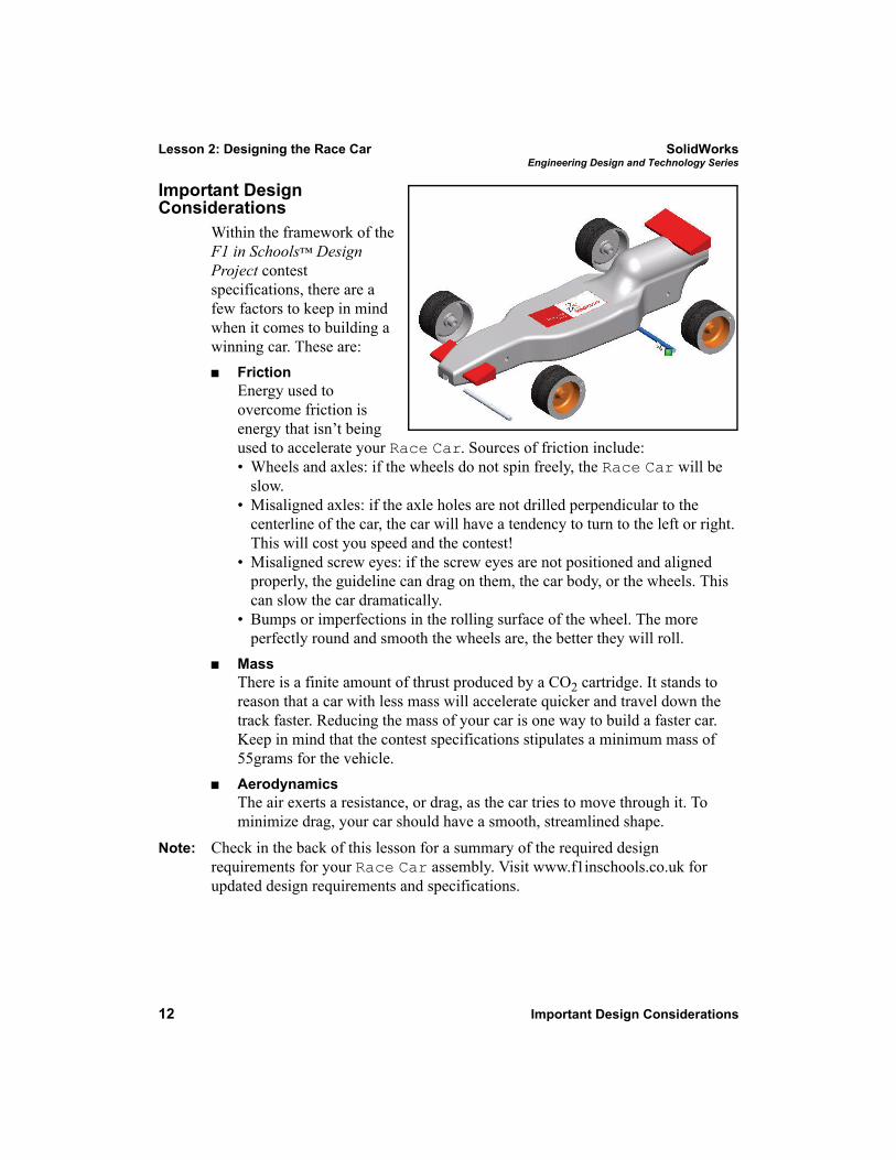
Within the framework of the F1 in Schools™ Design Project contest specifications, there are a few factors to keep in mind when it comes to building a winning car. These are:
FrictionEnergy used to overcome friction is energy that isn’t being used to accelerate your Race Car. Sources of friction include:• Wheels and axles: if the wheels do not spin freely, the Race Car will be
slow.• Misaligned axles: if the axle holes are not drilled perpendicular to the
centerline of the car, the car will have a tendency to turn to the left or right. This will cost you speed and the contest!
• Misaligned screw eyes: if the screw eyes are not positioned and aligned properly, the guideline can drag on them, the car body, or the wheels. This can slow the car dramatically.
• Bumps or imperfections in the rolling surface of the wheel. The more perfectly round and smooth the wheels are, the better they will roll.
MassThere is a finite amount of thrust produced by a CO2 cartridge. It stands to reason that a car with less mass will accelerate quicker and travel down the track faster. Reducing the mass of your car is one way to build a faster car. Keep in mind that the contest specifications stipulates a minimum mass of 55grams for the vehicle.AerodynamicsThe air exerts a resistance, or drag, as the car tries to move through it. To minimize drag, your car should have a smooth, streamlined shape.
Note: Check in the back of this lesson for a summary of the required design requirements for your Race Car assembly. Visit www.f1inschools.co.uk for updated design requirements and specifications.
SolidWorks Lesson 2: Designing the Race CarEngineering Design and Technology Series
About Balsa 13
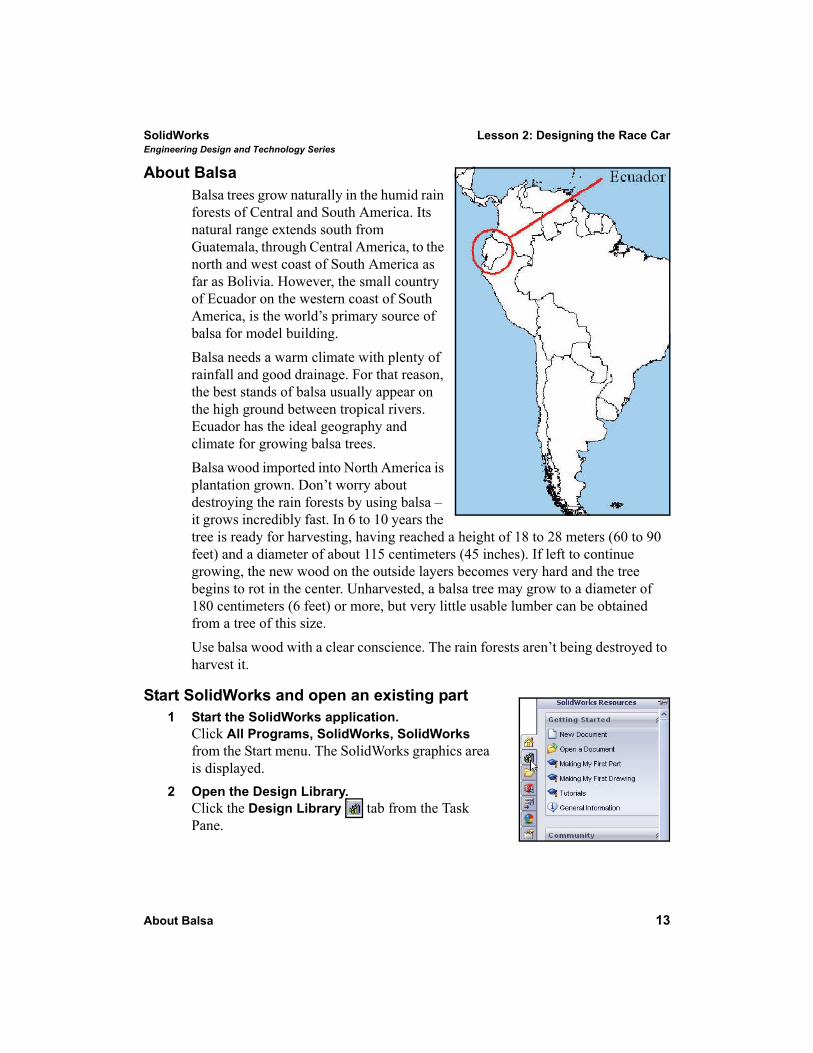
About BalsaBalsa trees grow naturally in the humid rain forests of Central and South America. Its natural range extends south from Guatemala, through Central America, to the north and west coast of South America as far as Bolivia. However, the small country of Ecuador on the western coast of South America, is the world’s primary source of balsa for model building. Balsa needs a warm climate with plenty of rainfall and good drainage. For that reason, the best stands of balsa usually appear on the high ground between tropical rivers. Ecuador has the ideal geography and climate for growing balsa trees.Balsa wood imported into North America is plantation grown. Don’t worry about destroying the rain forests by using balsa – it grows incredibly fast. In 6 to 10 years the tree is ready for harvesting, having reached a height of 18 to 28 meters (60 to 90 feet) and a diameter of about 115 centimeters (45 inches). If left to continue growing, the new wood on the outside layers becomes very hard and the tree begins to rot in the center. Unharvested, a balsa tree may grow to a diameter of 180 centimeters (6 feet) or more, but very little usable lumber can be obtained from a tree of this size.Use balsa wood with a clear conscience. The rain forests aren’t being destroyed to harvest it.
Start SolidWorks and open an existing part1 Start the SolidWorks application.
Click All Programs, SolidWorks, SolidWorks from the Start menu. The SolidWorks graphics area is displayed.
2 Open the Design Library.Click the Design Library tab from the Task Pane.
Lesson 2: Designing the Race Car SolidWorksEngineering Design and Technology Series
14 Start SolidWorks and open an existing part
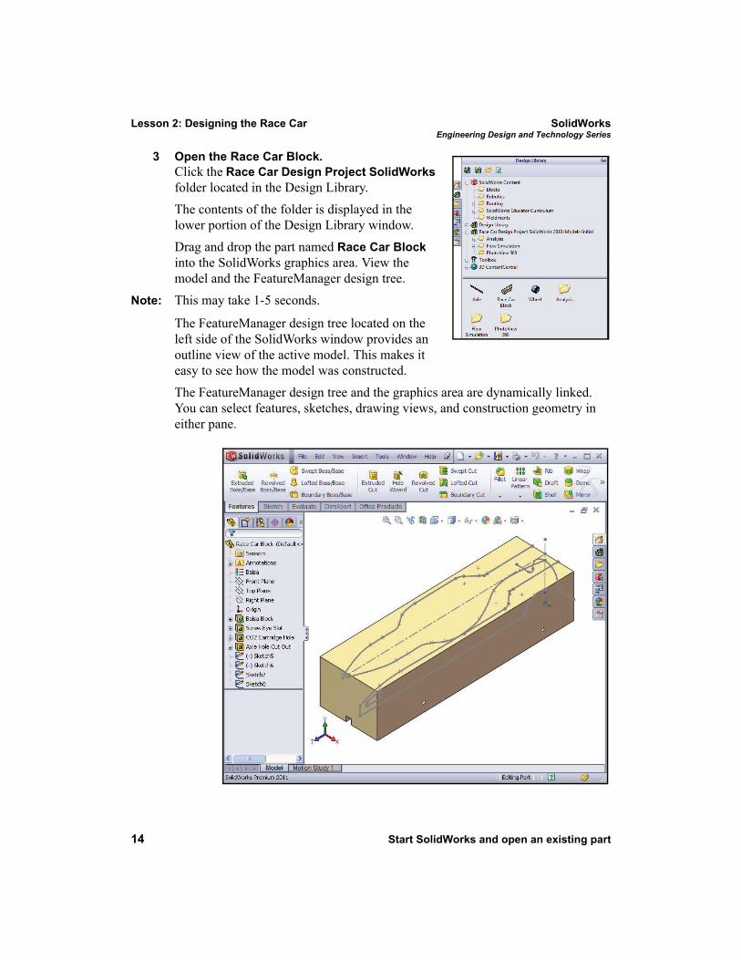
3 Open the Race Car Block.Click the Race Car Design Project SolidWorks folder located in the Design Library. The contents of the folder is displayed in the lower portion of the Design Library window. Drag and drop the part named Race Car Block into the SolidWorks graphics area. View the model and the FeatureManager design tree.
Note: This may take 1-5 seconds.
The FeatureManager design tree located on the left side of the SolidWorks window provides an outline view of the active model. This makes it easy to see how the model was constructed.
The FeatureManager design tree and the graphics area are dynamically linked. You can select features, sketches, drawing views, and construction geometry in either pane.
SolidWorks Lesson 2: Designing the Race CarEngineering Design and Technology Series
Start SolidWorks and open an existing part 15
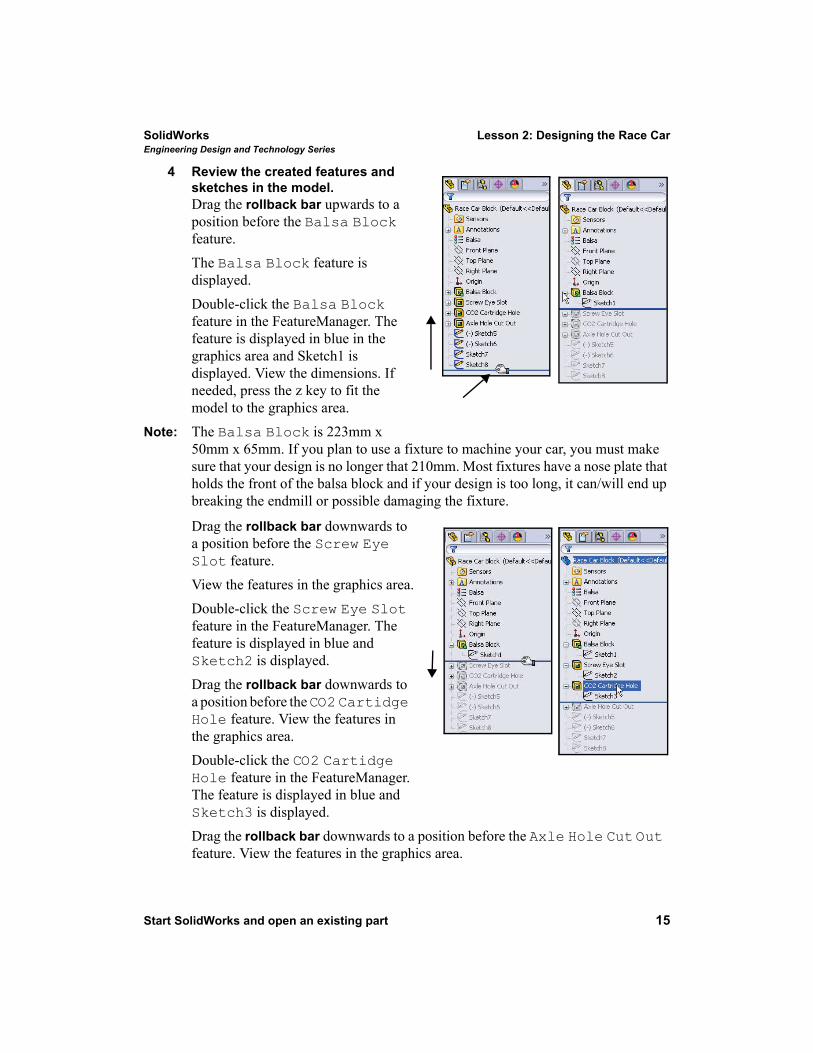
4 Review the created features and sketches in the model.Drag the rollback bar upwards to a position before the Balsa Block feature. The Balsa Block feature is displayed. Double-click the Balsa Block feature in the FeatureManager. The feature is displayed in blue in the graphics area and Sketch1 is displayed. View the dimensions. If needed, press the z key to fit the model to the graphics area.
Note: The Balsa Block is 223mm x 50mm x 65mm. If you plan to use a fixture to machine your car, you must make sure that your design is no longer that 210mm. Most fixtures have a nose plate that holds the front of the balsa block and if your design is too long, it can/will end up breaking the endmill or possible damaging the fixture.
Drag the rollback bar downwards to a position before the Screw Eye Slot feature. View the features in the graphics area.Double-click the Screw Eye Slot feature in the FeatureManager. The feature is displayed in blue and Sketch2 is displayed.Drag the rollback bar downwards to a position before the CO2 Cartidge Hole feature. View the features in the graphics area.Double-click the CO2 Cartidge Hole feature in the FeatureManager. The feature is displayed in blue and Sketch3 is displayed.Drag the rollback bar downwards to a position before the Axle Hole Cut Out feature. View the features in the graphics area.
Lesson 2: Designing the Race Car SolidWorksEngineering Design and Technology Series
16 Start SolidWorks and open an existing part
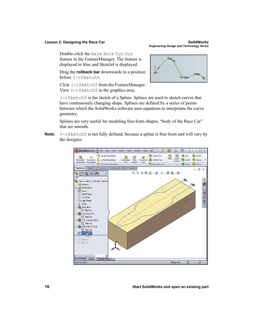
Double-click the Axle Hole Cut Out feature in the FeatureManager. The feature is displayed in blue and Sketch4 is displayed.Drag the rollback bar downwards to a position before (-)Sketch5. Click (-)Sketch5 from the FeatureManager. View (-)Sketch5 in the graphics area. (-)Sketch5 is the sketch of a Spline. Splines are used to sketch curves that have continuously changing shape. Splines are defined by a series of points between which the SolidWorks software uses equations to interpolate the curve geometry.Splines are very useful for modeling free-form shapes, “body of the Race Car” that are smooth.
Note: (-)Sketch5 is not fully defined, because a spline is free-form and will vary by the designer.
SolidWorks Lesson 2: Designing the Race CarEngineering Design and Technology Series
Extruded Cut Feature 17
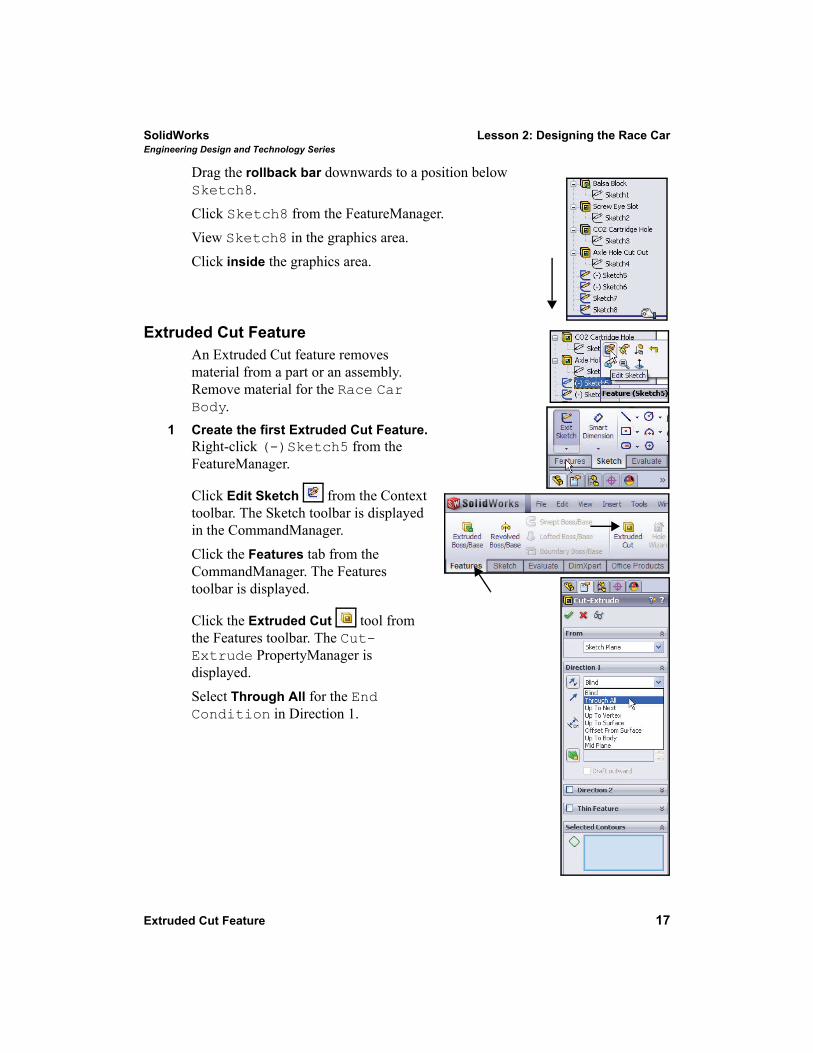
Drag the rollback bar downwards to a position below Sketch8. Click Sketch8 from the FeatureManager. View Sketch8 in the graphics area. Click inside the graphics area.
Extruded Cut FeatureAn Extruded Cut feature removes material from a part or an assembly. Remove material for the Race Car Body.
1 Create the first Extruded Cut Feature.Right-click (-)Sketch5 from the FeatureManager.
Click Edit Sketch from the Context toolbar. The Sketch toolbar is displayed in the CommandManager.Click the Features tab from the CommandManager. The Features toolbar is displayed.
Click the Extruded Cut tool from the Features toolbar. The Cut-Extrude PropertyManager is displayed.Select Through All for the End Condition in Direction 1.
Lesson 2: Designing the Race Car SolidWorksEngineering Design and Technology Series
18 Extruded Cut Feature
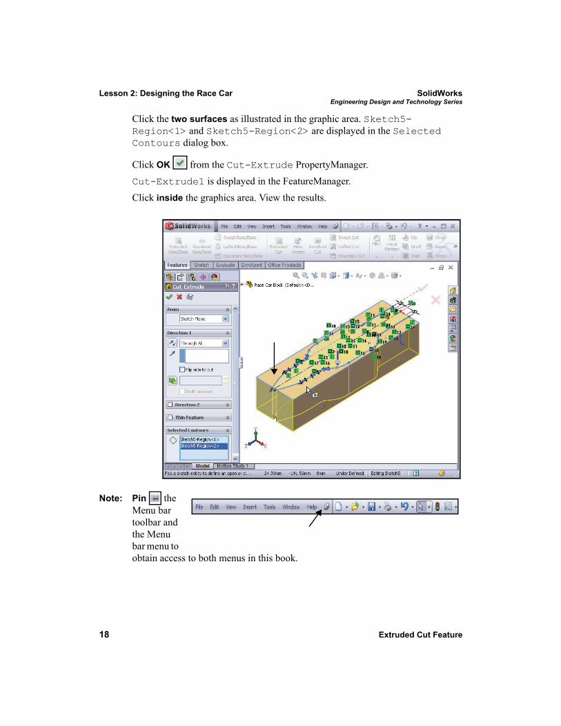
Click the two surfaces as illustrated in the graphic area. Sketch5-Region<1> and Sketch5-Region<2> are displayed in the Selected Contours dialog box.
Click OK from the Cut-Extrude PropertyManager. Cut-Extrude1 is displayed in the FeatureManager.Click inside the graphics area. View the results.
Note: Pin the Menu bar toolbar and the Menu bar menu to obtain access to both menus in this book.
SolidWorks Lesson 2: Designing the Race CarEngineering Design and Technology Series
Extruded Cut Feature 19
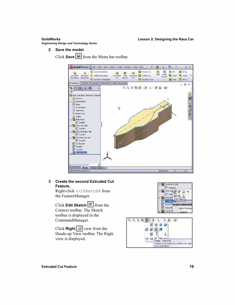
2 Save the model.
Click Save from the Menu bar toolbar.
3 Create the second Extruded Cut Feature.Right-click (-)Sketch6 from the FeatureManager.
Click Edit Sketch from the Context toolbar. The Sketch toolbar is displayed in the CommandManager.
Click Right view from the Heads-up View toolbar. The Right view is displayed.
Lesson 2: Designing the Race Car SolidWorksEngineering Design and Technology Series
20 Extruded Cut Feature
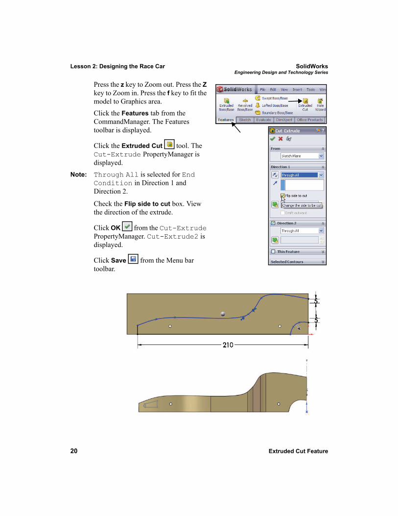
Press the z key to Zoom out. Press the Z key to Zoom in. Press the f key to fit the model to Graphics area.Click the Features tab from the CommandManager. The Features toolbar is displayed.
Click the Extruded Cut tool. The Cut-Extrude PropertyManager is displayed.
Note: Through All is selected for End Condition in Direction 1 and Direction 2.
Check the Flip side to cut box. View the direction of the extrude.
Click OK from the Cut-Extrude PropertyManager. Cut-Extrude2 is displayed.
Click Save from the Menu bar toolbar.
SolidWorks Lesson 2: Designing the Race CarEngineering Design and Technology Series
Extruded Cut Feature 21
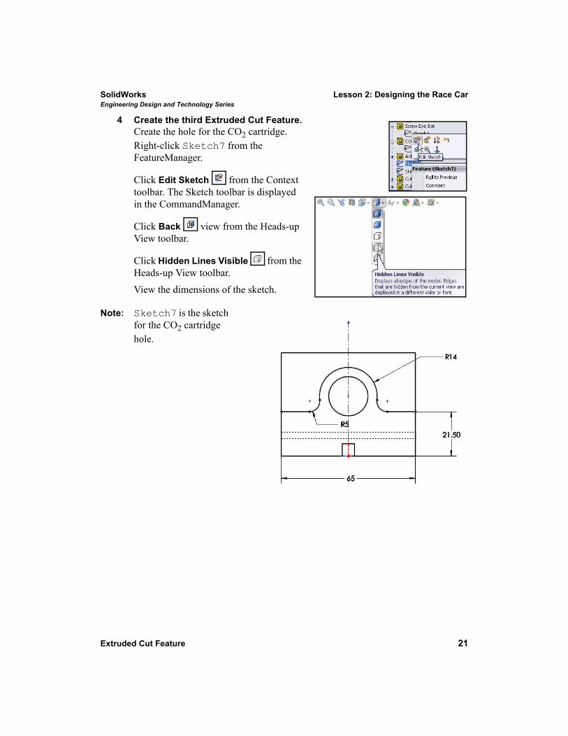
4 Create the third Extruded Cut Feature.Create the hole for the CO2 cartridge. Right-click Sketch7 from the FeatureManager.
Click Edit Sketch from the Context toolbar. The Sketch toolbar is displayed in the CommandManager.
Click Back view from the Heads-up View toolbar.
Click Hidden Lines Visible from the Heads-up View toolbar. View the dimensions of the sketch.
Note: Sketch7 is the sketch for the CO2 cartridge hole.
Lesson 2: Designing the Race Car SolidWorksEngineering Design and Technology Series
22 Extruded Cut Feature
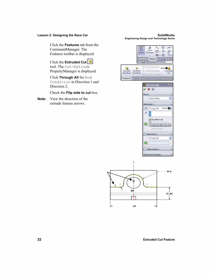
Click the Features tab from the CommandManager. The Features toolbar is displayed.
Click the Extruded Cut tool. The Cut-Extrude PropertyManager is displayed. Click Through All for End Condition in Direction 1 and Direction 2.
Check the Flip side to cut box.Note: View the direction of the
extrude feature arrows.
SolidWorks Lesson 2: Designing the Race CarEngineering Design and Technology Series
Extruded Cut Feature 23
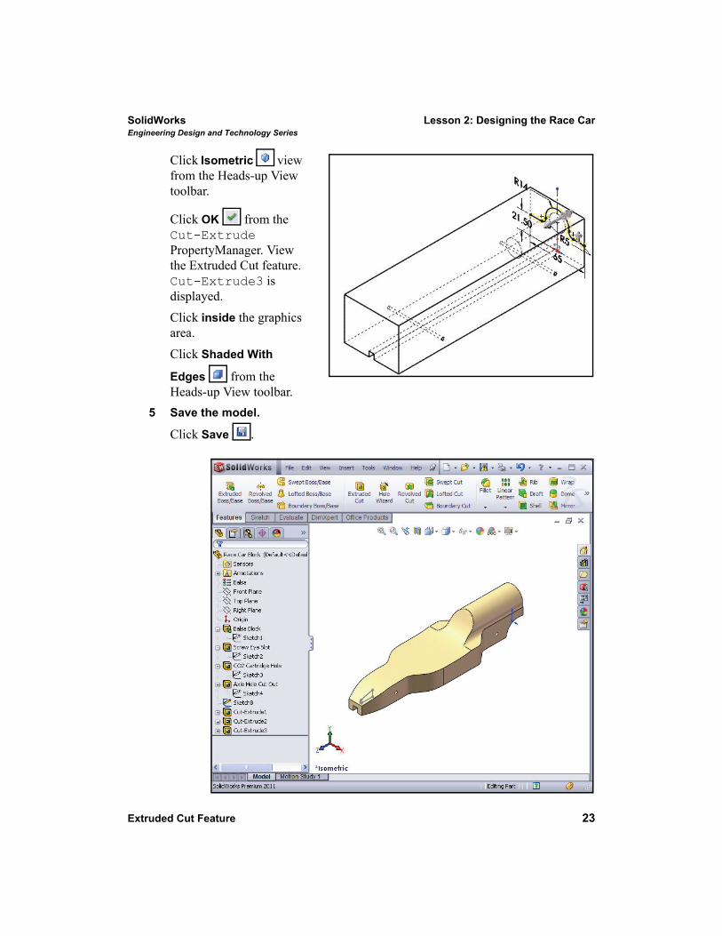
Click Isometric view from the Heads-up View toolbar.
Click OK from the Cut-Extrude PropertyManager. View the Extruded Cut feature. Cut-Extrude3 is displayed.Click inside the graphics area.Click Shaded With
Edges from the Heads-up View toolbar.
5 Save the model.
Click Save .
Lesson 2: Designing the Race Car SolidWorksEngineering Design and Technology Series
24 Create the Front Wing
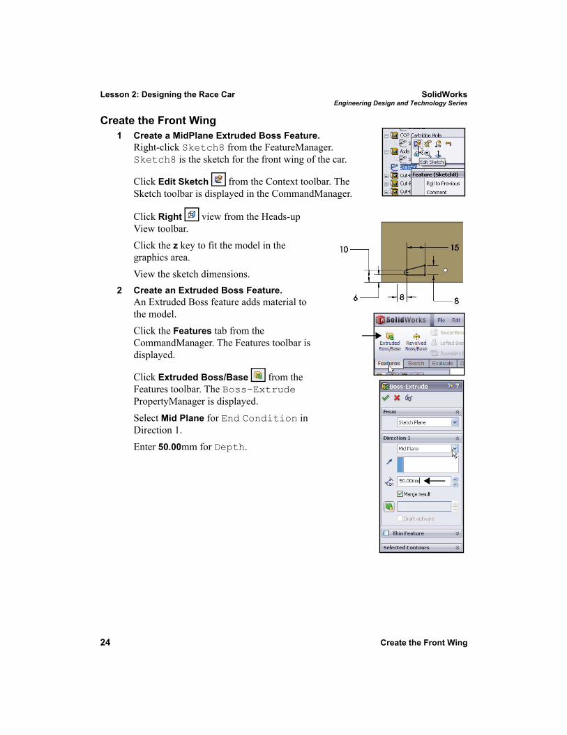
Create the Front Wing 1 Create a MidPlane Extruded Boss Feature.
Right-click Sketch8 from the FeatureManager. Sketch8 is the sketch for the front wing of the car.
Click Edit Sketch from the Context toolbar. The Sketch toolbar is displayed in the CommandManager.
Click Right view from the Heads-up View toolbar.Click the z key to fit the model in the graphics area. View the sketch dimensions.
2 Create an Extruded Boss Feature.An Extruded Boss feature adds material to the model. Click the Features tab from the CommandManager. The Features toolbar is displayed.
Click Extruded Boss/Base from the Features toolbar. The Boss-Extrude PropertyManager is displayed. Select Mid Plane for End Condition in Direction 1.Enter 50.00mm for Depth.
SolidWorks Lesson 2: Designing the Race CarEngineering Design and Technology Series
Create the Front Wing 25
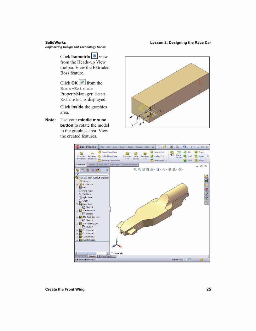
Click Isometric view from the Heads-up View toolbar. View the Extruded Boss feature.
Click OK from the Boss-Extrude PropertyManager. Boss-Extrude1 is displayed.Click inside the graphics area.
Note: Use your middle mouse button to rotate the model in the graphics area. View the created features.
Lesson 2: Designing the Race Car SolidWorksEngineering Design and Technology Series
26 Create the Rear Wing
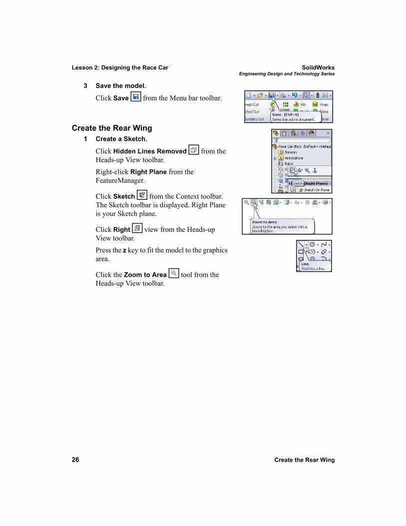
3 Save the model.
Click Save from the Menu bar toolbar.
Create the Rear Wing1 Create a Sketch.
Click Hidden Lines Removed from the Heads-up View toolbar.
Right-click Right Plane from the FeatureManager.
Click Sketch from the Context toolbar. The Sketch toolbar is displayed. Right Plane is your Sketch plane.
Click Right view from the Heads-up View toolbar. Press the z key to fit the model to the graphics area.
Click the Zoom to Area tool from the Heads-up View toolbar.
SolidWorks Lesson 2: Designing the Race CarEngineering Design and Technology Series
Create the Rear Wing 27
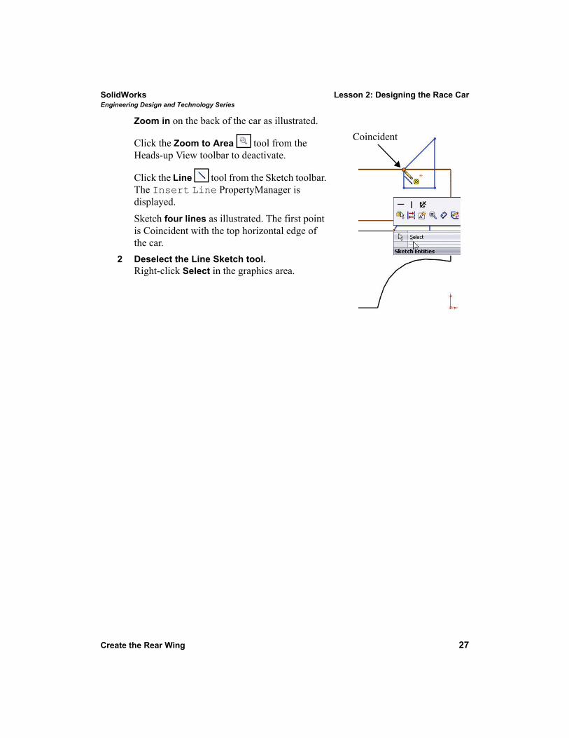
Zoom in on the back of the car as illustrated.
Click the Zoom to Area tool from the Heads-up View toolbar to deactivate.
Click the Line tool from the Sketch toolbar. The Insert Line PropertyManager is displayed.Sketch four lines as illustrated. The first point is Coincident with the top horizontal edge of the car.
2 Deselect the Line Sketch tool.Right-click Select in the graphics area.
Coincident
Lesson 2: Designing the Race Car SolidWorksEngineering Design and Technology Series
28 Create the Rear Wing
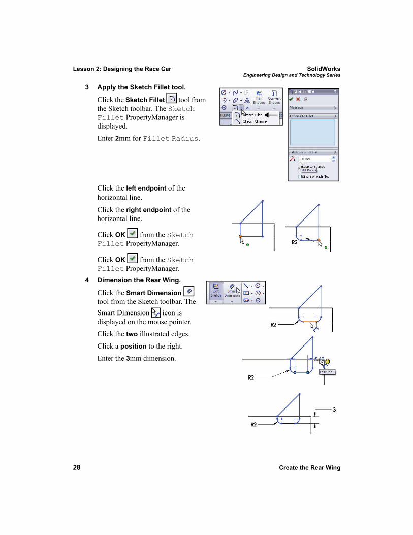
3 Apply the Sketch Fillet tool.
Click the Sketch Fillet tool from the Sketch toolbar. The Sketch Fillet PropertyManager is displayed.Enter 2mm for Fillet Radius.
Click the left endpoint of the horizontal line.Click the right endpoint of the horizontal line.
Click OK from the Sketch Fillet PropertyManager.
Click OK from the Sketch Fillet PropertyManager.
4 Dimension the Rear Wing.
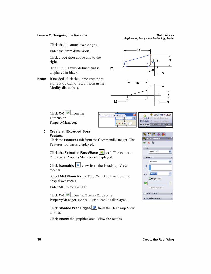
Click the Smart Dimension tool from the Sketch toolbar. The Smart Dimension icon is displayed on the mouse pointer.Click the two illustrated edges.Click a position to the right.Enter the 3mm dimension.
SolidWorks Lesson 2: Designing the Race CarEngineering Design and Technology Series
Create the Rear Wing 29
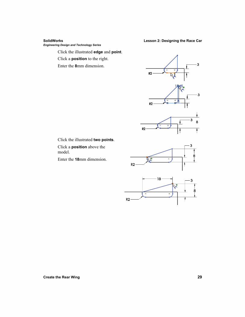
Click the illustrated edge and point.Click a position to the right.Enter the 8mm dimension.
Click the illustrated two points.Click a position above the model.
Enter the 18mm dimension.
Lesson 2: Designing the Race Car SolidWorksEngineering Design and Technology Series
30 Create the Rear Wing
Click the illustrated two edges.Enter the 6mm dimension. Click a position above and to the right. Sketch9 is fully defined and is displayed in black.
Note: If needed, click the Reverse the sense of dimension icon in the Modify dialog box.
Click OK from the Dimension PropertyManager.
5 Create an Extruded Boss Feature.Click the Features tab from the CommandManager. The Features toolbar is displayed.
Click the Extruded Boss/Base tool. The Boss-Extrude PropertyManager is displayed.
Click Isometric view from the Heads-up View toolbar.Select Mid Plane for the End Condition from the drop-down menu.Enter 50mm for Depth.
Click OK from the Boss-Extrude PropertyManager. Boss-Extrude2 is displayed.
Click Shaded With Edges from the Heads-up View toolbar. Click inside the graphics area. View the results.
SolidWorks Lesson 2: Designing the Race CarEngineering Design and Technology Series
Create the Rear Wing 31
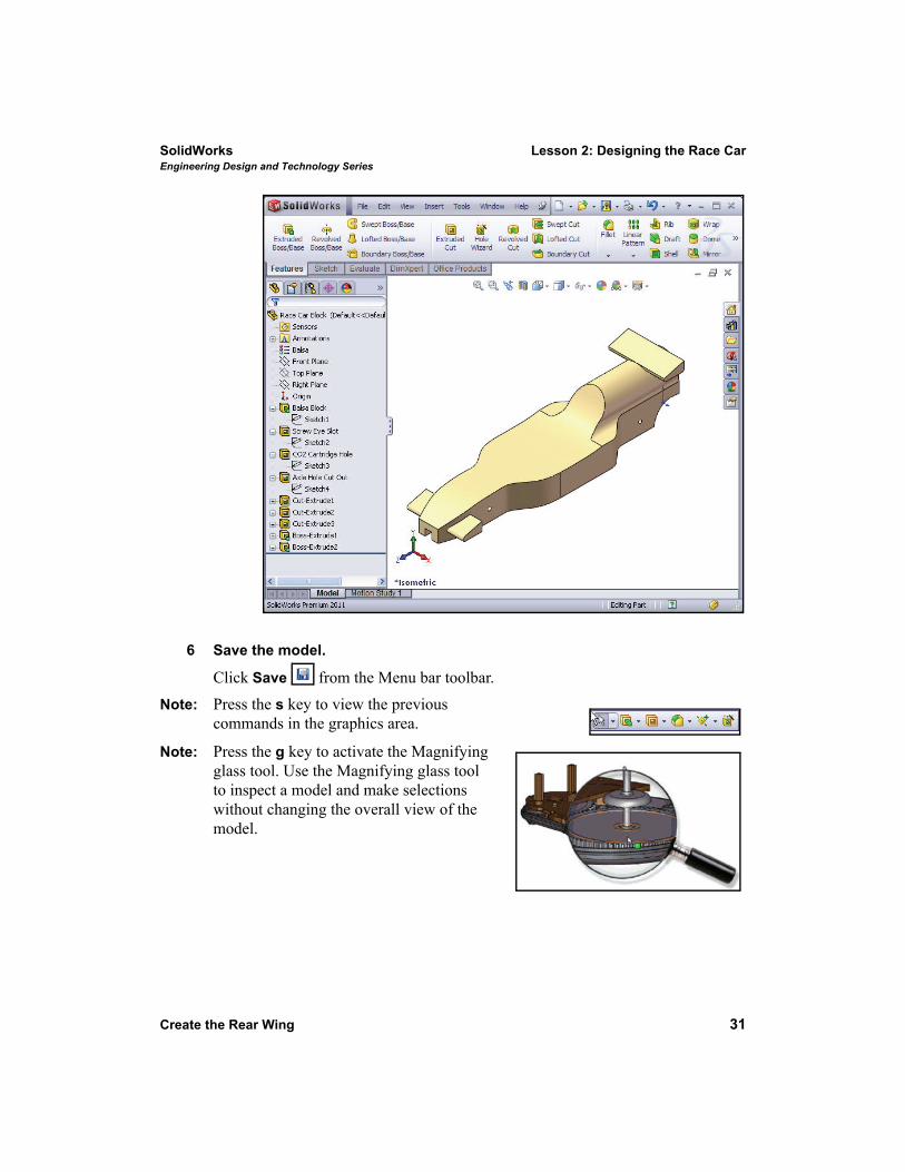
6 Save the model.
Click Save from the Menu bar toolbar.Note: Press the s key to view the previous
commands in the graphics area.
Note: Press the g key to activate the Magnifying glass tool. Use the Magnifying glass tool to inspect a model and make selections without changing the overall view of the model.
Lesson 2: Designing the Race Car SolidWorksEngineering Design and Technology Series
32 Insert Fillets
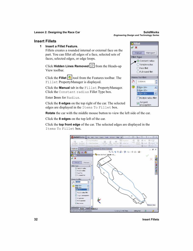
Insert Fillets1 Insert a Fillet Feature.
Fillets creates a rounded internal or external face on the part. You can fillet all edges of a face, selected sets of faces, selected edges, or edge loops.
Click Hidden Lines Removed from the Heads-up View toolbar.
Click the Fillet tool from the Features toolbar. The Fillet PropertyManager is displayed.Click the Manual tab in the Fillet PropertyManager. Click the Constant radius Fillet Type box.Enter 3mm for Radius.Click the 8 edges on the top right of the car. The selected edges are displayed in the Items To Fillet box.Rotate the car with the middle mouse button to view the left side of the car.Click the 8 edges on the top left of the car.Click the top front edge of the car. The selected edges are displayed in the Items To Fillet box.
SolidWorks Lesson 2: Designing the Race CarEngineering Design and Technology Series
Insert Fillets 33
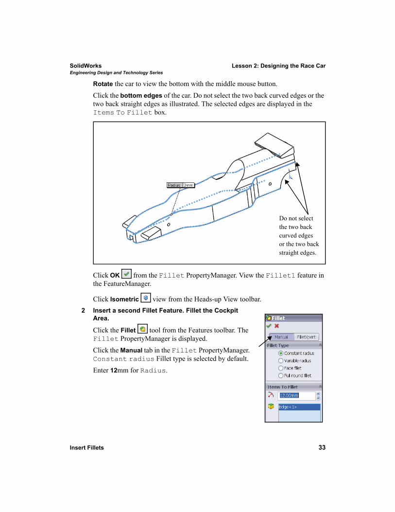
Rotate the car to view the bottom with the middle mouse button.Click the bottom edges of the car. Do not select the two back curved edges or the two back straight edges as illustrated. The selected edges are displayed in the Items To Fillet box.
Click OK from the Fillet PropertyManager. View the Fillet1 feature in the FeatureManager.
Click Isometric view from the Heads-up View toolbar.2 Insert a second Fillet Feature. Fillet the Cockpit
Area.
Click the Fillet tool from the Features toolbar. The Fillet PropertyManager is displayed.Click the Manual tab in the Fillet PropertyManager. Constant radius Fillet type is selected by default.Enter 12mm for Radius.
Do not selectthe two backcurved edgesor the two backstraight edges.
Lesson 2: Designing the Race Car SolidWorksEngineering Design and Technology Series
34 Insert Fillets
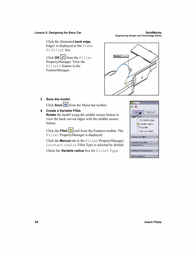
Click the illustrated back edge. Edge1 is displayed in the Items To Fillet box.
Click OK from the Fillet PropertyManager. View the Fillet2 feature in the FeatureManager.
3 Save the model.
Click Save from the Menu bar toolbar.4 Create a Variable Fillet.
Rotate the model using the middle mouse button to view the back curved edges with the middle mouse button.
Click the Fillet tool from the Features toolbar. The Fillet PropertyManager is displayed.Click the Manual tab in the Fillet PropertyManager. Constant radius Fillet Type is selected by default.Check the Variable radius box for Fillet Type.
SolidWorks Lesson 2: Designing the Race CarEngineering Design and Technology Series
Insert Fillets 35
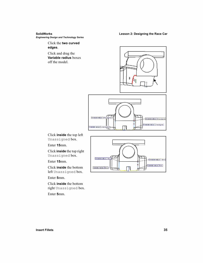
Click the two curved edges.Click and drag the Variable radius boxes off the model.
Click inside the top left Unassigned box.Enter 15mm.Click inside the top right Unassigned box.Enter 15mm.Click inside the bottom left Unassigned box.Enter 5mm.Click inside the bottom right Unassigned box.Enter 5mm.
Lesson 2: Designing the Race Car SolidWorksEngineering Design and Technology Series
36 Insert Fillets
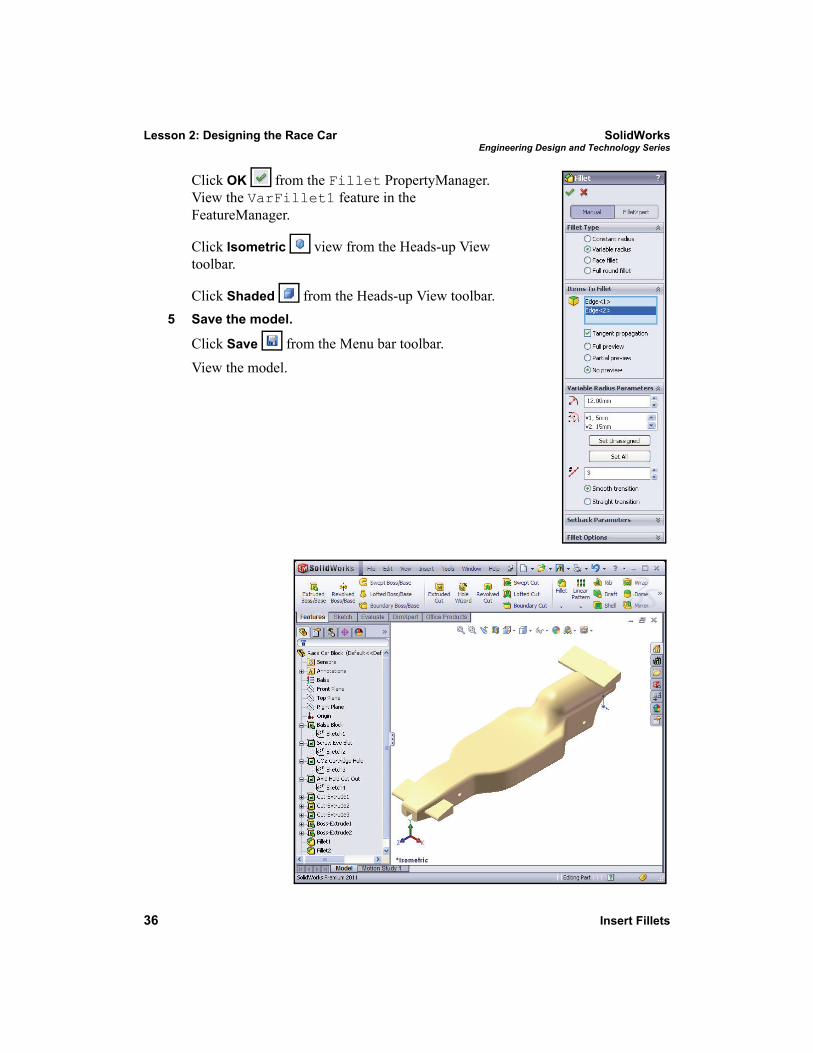
Click OK from the Fillet PropertyManager. View the VarFillet1 feature in the FeatureManager.
Click Isometric view from the Heads-up View toolbar.
Click Shaded from the Heads-up View toolbar.5 Save the model.
Click Save from the Menu bar toolbar. View the model.
SolidWorks Lesson 2: Designing the Race CarEngineering Design and Technology Series
Create an Assembly 37
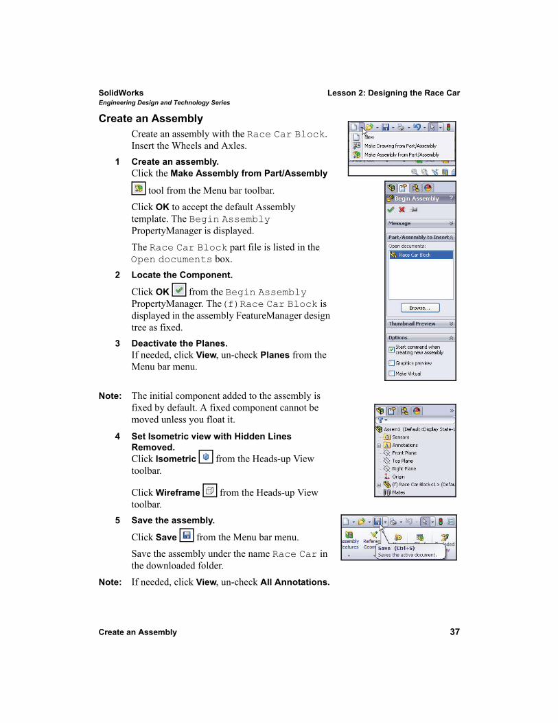
Create an AssemblyCreate an assembly with the Race Car Block. Insert the Wheels and Axles.
1 Create an assembly.Click the Make Assembly from Part/Assembly
tool from the Menu bar toolbar.Click OK to accept the default Assembly template. The Begin Assembly PropertyManager is displayed.The Race Car Block part file is listed in the Open documents box.
2 Locate the Component.
Click OK from the Begin Assembly PropertyManager. The(f)Race Car Block is displayed in the assembly FeatureManager design tree as fixed.
3 Deactivate the Planes.If needed, click View, un-check Planes from the Menu bar menu.
Note: The initial component added to the assembly is fixed by default. A fixed component cannot be moved unless you float it.
4 Set Isometric view with Hidden Lines Removed.Click Isometric from the Heads-up View toolbar.
Click Wireframe from the Heads-up View toolbar.
5 Save the assembly.
Click Save from the Menu bar menu.Save the assembly under the name Race Car in the downloaded folder.
Note: If needed, click View, un-check All Annotations.
Lesson 2: Designing the Race Car SolidWorksEngineering Design and Technology Series
38 Create an Assembly
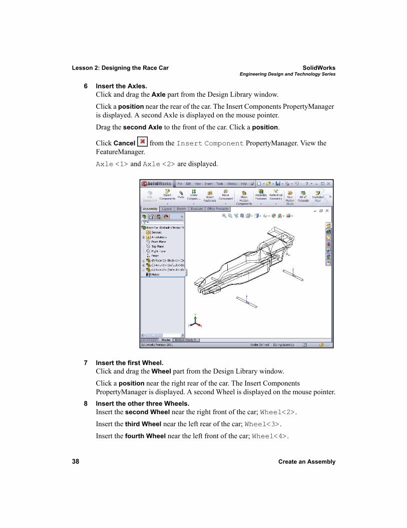
6 Insert the Axles.Click and drag the Axle part from the Design Library window.Click a position near the rear of the car. The Insert Components PropertyManager is displayed. A second Axle is displayed on the mouse pointer.Drag the second Axle to the front of the car. Click a position.
Click Cancel from the Insert Component PropertyManager. View the FeatureManager. Axle <1> and Axle <2> are displayed.
7 Insert the first Wheel.Click and drag the Wheel part from the Design Library window.Click a position near the right rear of the car. The Insert Components PropertyManager is displayed. A second Wheel is displayed on the mouse pointer.
8 Insert the other three Wheels.Insert the second Wheel near the right front of the car; Wheel<2>.Insert the third Wheel near the left rear of the car; Wheel<3>.Insert the fourth Wheel near the left front of the car; Wheel<4>.
SolidWorks Lesson 2: Designing the Race CarEngineering Design and Technology Series
Create an Assembly 39
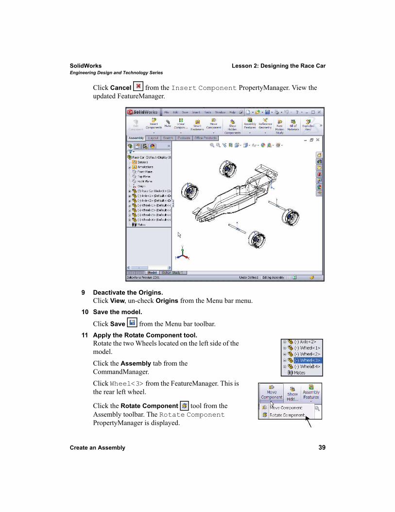
Click Cancel from the Insert Component PropertyManager. View the updated FeatureManager.
9 Deactivate the Origins.Click View, un-check Origins from the Menu bar menu.
10 Save the model.
Click Save from the Menu bar toolbar. 11 Apply the Rotate Component tool.
Rotate the two Wheels located on the left side of the model. Click the Assembly tab from the CommandManager.Click Wheel<3> from the FeatureManager. This is the rear left wheel.
Click the Rotate Component tool from the Assembly toolbar. The Rotate Component PropertyManager is displayed.
Lesson 2: Designing the Race Car SolidWorksEngineering Design and Technology Series
40 Create an Assembly
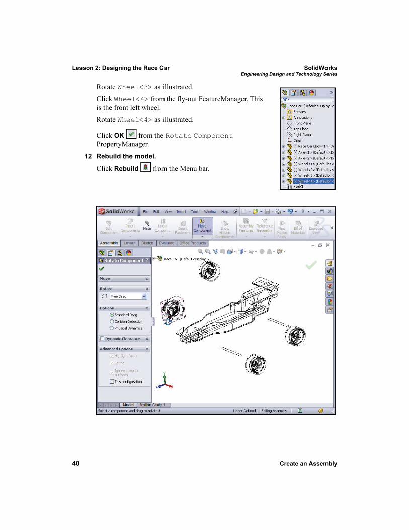
Rotate Wheel<3> as illustrated.Click Wheel<4> from the fly-out FeatureManager. This is the front left wheel.Rotate Wheel<4> as illustrated.
Click OK from the Rotate Component PropertyManager.
12 Rebuild the model.
Click Rebuild from the Menu bar.
SolidWorks Lesson 2: Designing the Race CarEngineering Design and Technology Series
Insert Mates 41
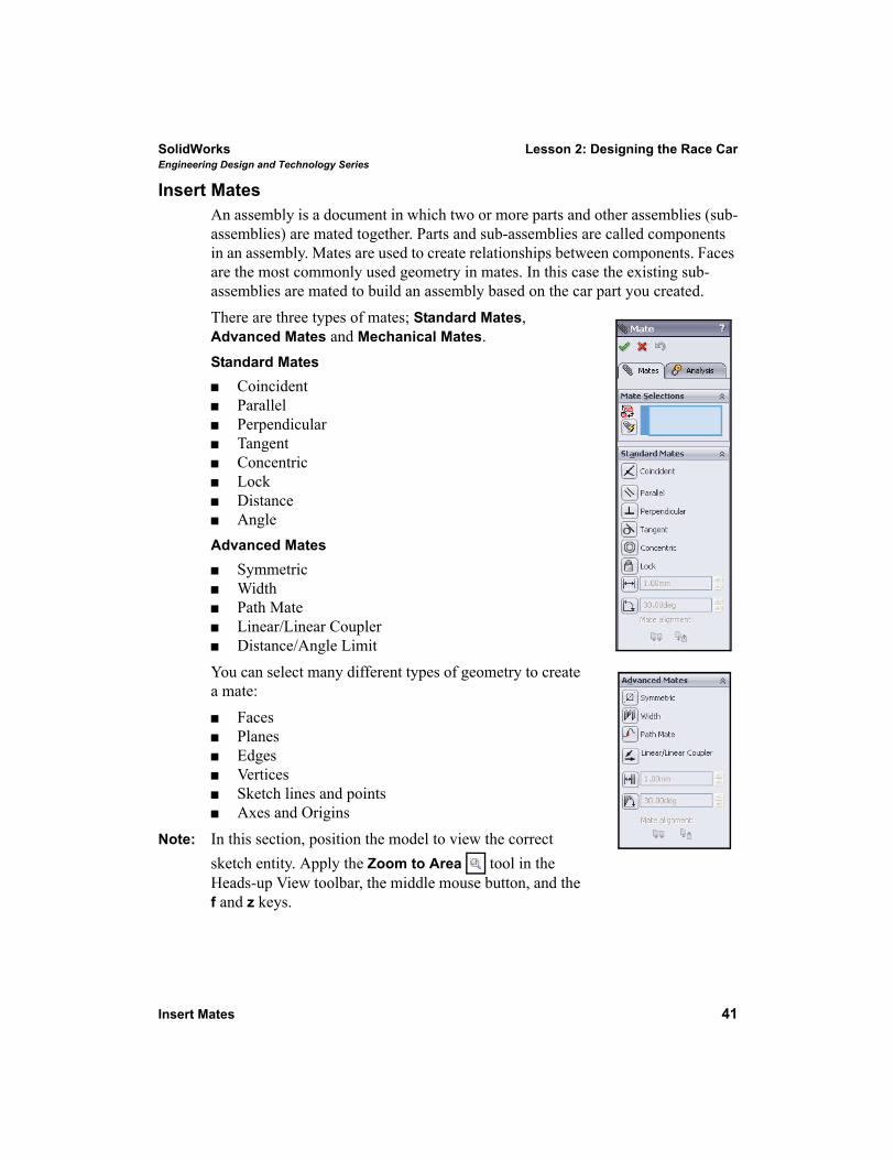
Insert MatesAn assembly is a document in which two or more parts and other assemblies (sub-assemblies) are mated together. Parts and sub-assemblies are called components in an assembly. Mates are used to create relationships between components. Faces are the most commonly used geometry in mates. In this case the existing sub- assemblies are mated to build an assembly based on the car part you created.There are three types of mates; Standard Mates, Advanced Mates and Mechanical Mates.Standard Mates
CoincidentParallelPerpendicularTangentConcentricLockDistanceAngle
Advanced MatesSymmetricWidthPath MateLinear/Linear CouplerDistance/Angle Limit
You can select many different types of geometry to create a mate:
FacesPlanesEdgesVerticesSketch lines and pointsAxes and Origins
Note: In this section, position the model to view the correct sketch entity. Apply the Zoom to Area tool in the Heads-up View toolbar, the middle mouse button, and the f and z keys.
Lesson 2: Designing the Race Car SolidWorksEngineering Design and Technology Series
42 Insert Mates
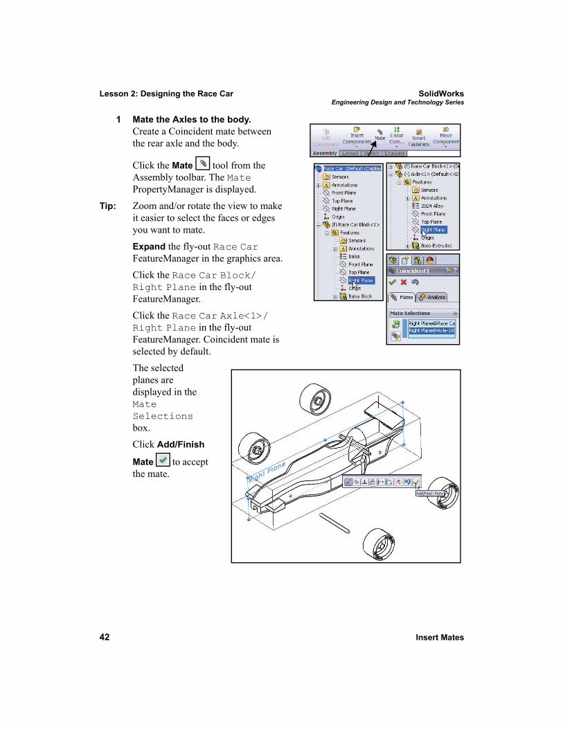
1 Mate the Axles to the body.Create a Coincident mate between the rear axle and the body.
Click the Mate tool from the Assembly toolbar. The Mate PropertyManager is displayed.
Tip: Zoom and/or rotate the view to make it easier to select the faces or edges you want to mate.
Expand the fly-out Race Car FeatureManager in the graphics area.Click the Race Car Block/Right Plane in the fly-out FeatureManager. Click the Race Car Axle<1>/Right Plane in the fly-out FeatureManager. Coincident mate is selected by default. The selected planes are displayed in the Mate Selections box.Click Add/Finish
Mate to accept the mate.
SolidWorks Lesson 2: Designing the Race CarEngineering Design and Technology Series
Insert Mates 43
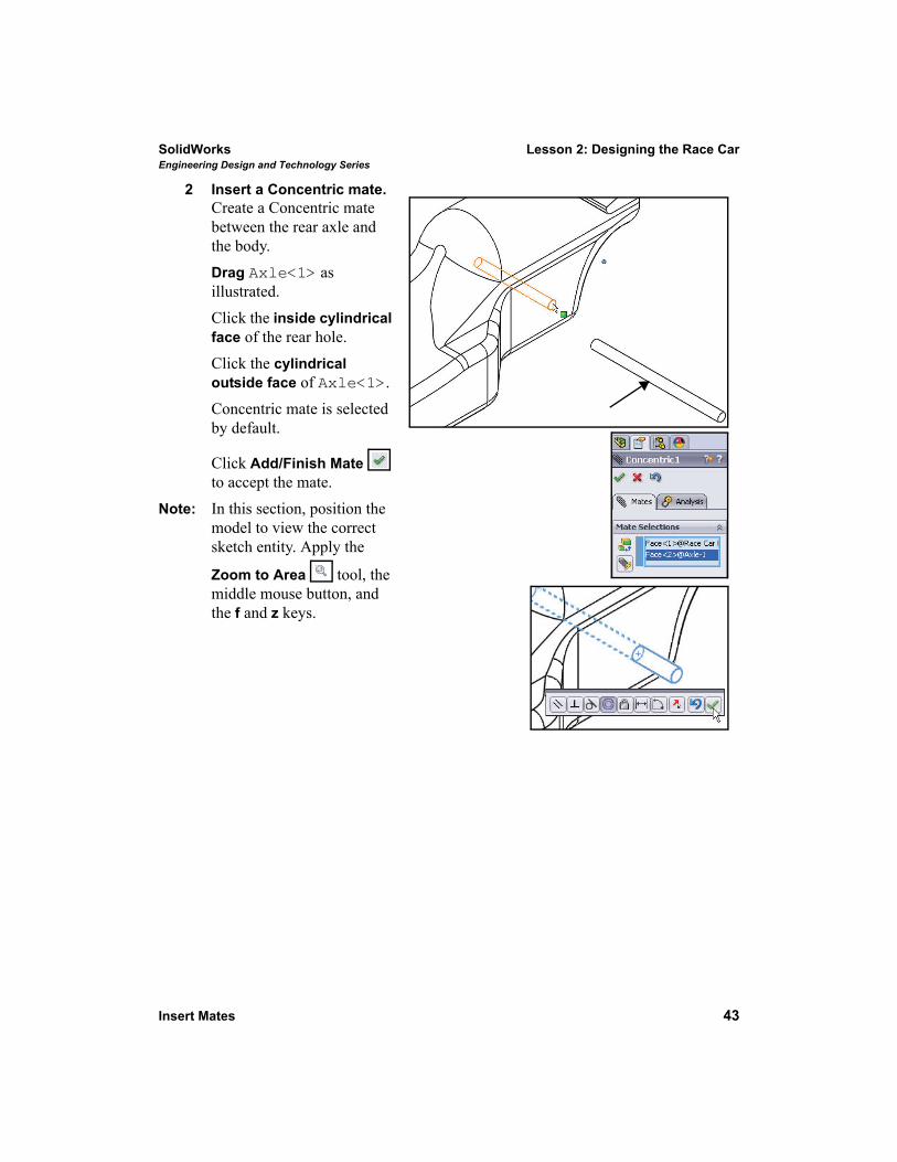
2 Insert a Concentric mate.Create a Concentric mate between the rear axle and the body. Drag Axle<1> as illustrated.Click the inside cylindrical face of the rear hole.Click the cylindrical outside face of Axle<1>. Concentric mate is selected by default.
Click Add/Finish Mate to accept the mate.
Note: In this section, position the model to view the correct sketch entity. Apply the
Zoom to Area tool, the middle mouse button, and the f and z keys.
Lesson 2: Designing the Race Car SolidWorksEngineering Design and Technology Series
44 Insert Mates
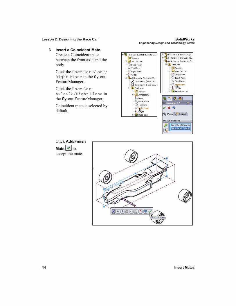
3 Insert a Coincident Mate.Create a Coincident mate between the front axle and the body. Click the Race Car Block/Right Plane in the fly-out FeatureManager. Click the Race Car Axle<2>/Right Plane in the fly-out FeatureManager. Coincident mate is selected by default.
Click Add/Finish
Mate to accept the mate.
SolidWorks Lesson 2: Designing the Race CarEngineering Design and Technology Series
Insert Mates 45
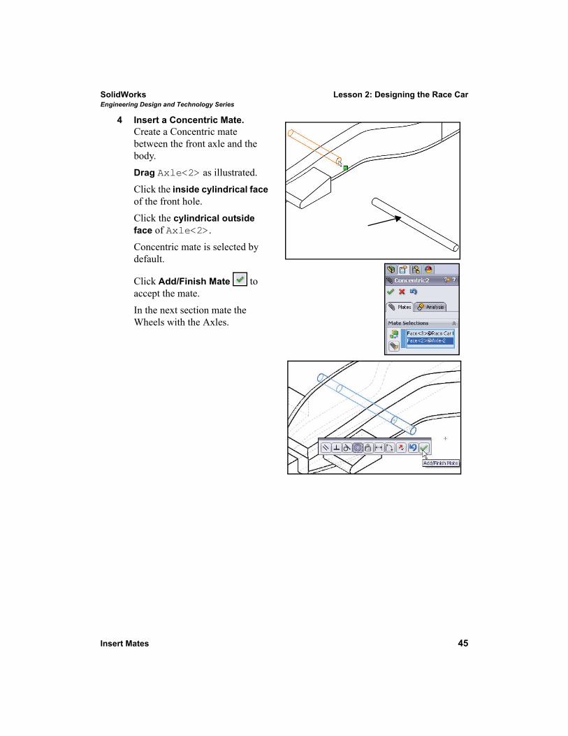
4 Insert a Concentric Mate.Create a Concentric mate between the front axle and the body. Drag Axle<2> as illustrated.Click the inside cylindrical face of the front hole.Click the cylindrical outside face of Axle<2>. Concentric mate is selected by default.
Click Add/Finish Mate to accept the mate. In the next section mate the Wheels with the Axles.
Lesson 2: Designing the Race Car SolidWorksEngineering Design and Technology Series
46 Insert Mates
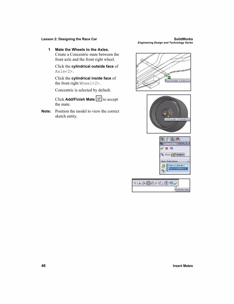
1 Mate the Wheels to the Axles.Create a Concentric mate between the front axle and the front right wheel.Click the cylindrical outside face of Axle<2>. Click the cylindrical inside face of the front right Wheel<2>. Concentric is selected by default.
Click Add/Finish Mate to accept the mate.
Note: Position the model to view the correct sketch entity.
SolidWorks Lesson 2: Designing the Race CarEngineering Design and Technology Series
Insert Mates 47
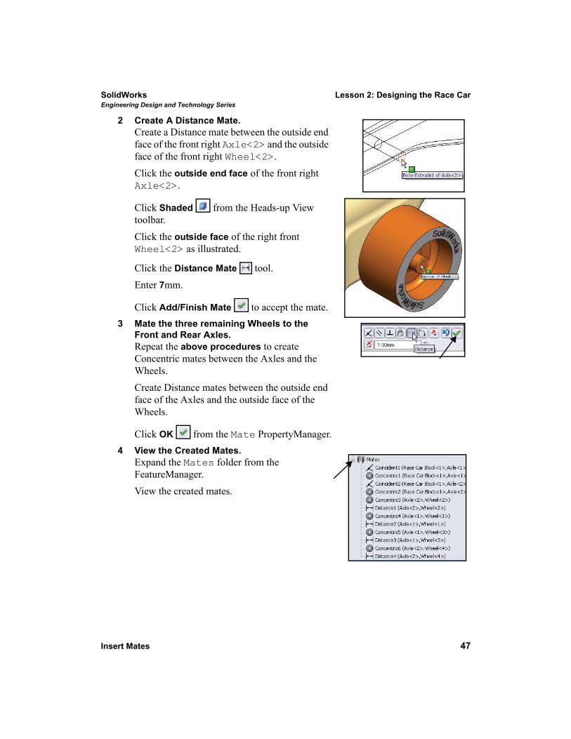
2 Create A Distance Mate.Create a Distance mate between the outside end face of the front right Axle<2> and the outside face of the front right Wheel<2>. Click the outside end face of the front right Axle<2>.
Click Shaded from the Heads-up View toolbar.Click the outside face of the right front Wheel<2> as illustrated.
Click the Distance Mate tool.Enter 7mm.
Click Add/Finish Mate to accept the mate.3 Mate the three remaining Wheels to the
Front and Rear Axles.Repeat the above procedures to create Concentric mates between the Axles and the Wheels. Create Distance mates between the outside end face of the Axles and the outside face of the Wheels.
Click OK from the Mate PropertyManager.4 View the Created Mates.
Expand the Mates folder from the FeatureManager. View the created mates.
Lesson 2: Designing the Race Car SolidWorksEngineering Design and Technology Series
48 Insert Mates
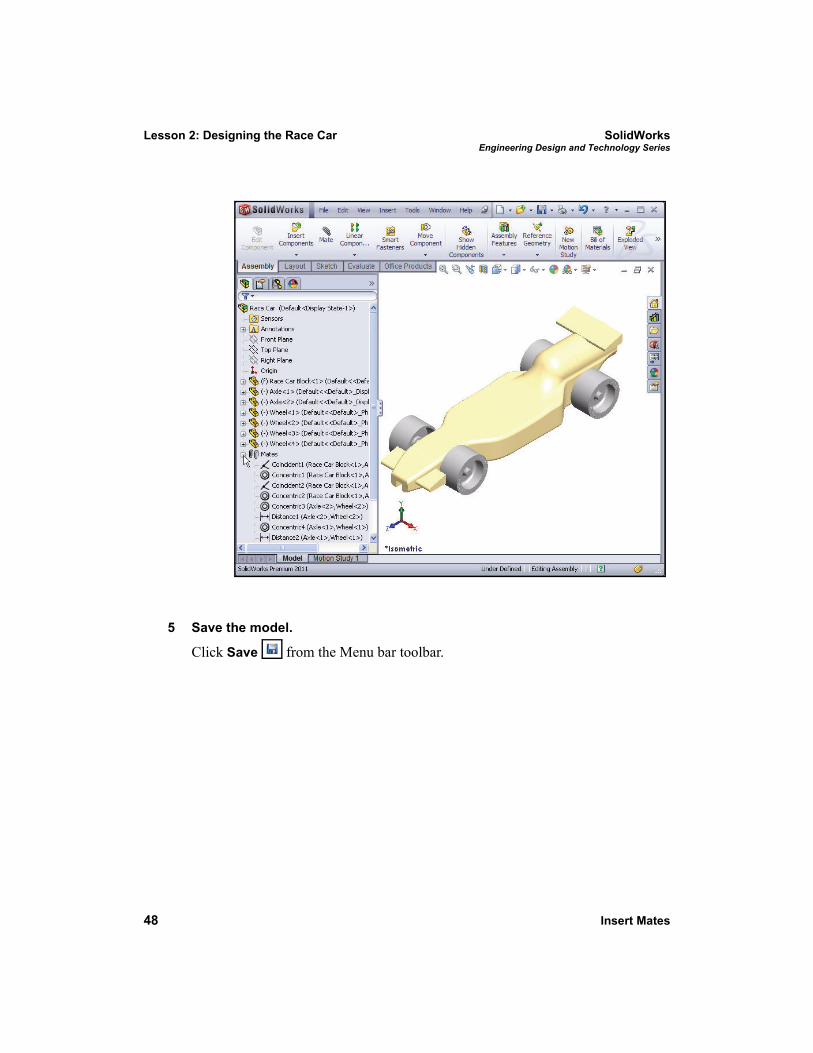
5 Save the model.
Click Save from the Menu bar toolbar.
SolidWorks Lesson 2: Designing the Race CarEngineering Design and Technology Series
Calculate the Weight of the Race Car 49
Calculate the Weight of the Race Car
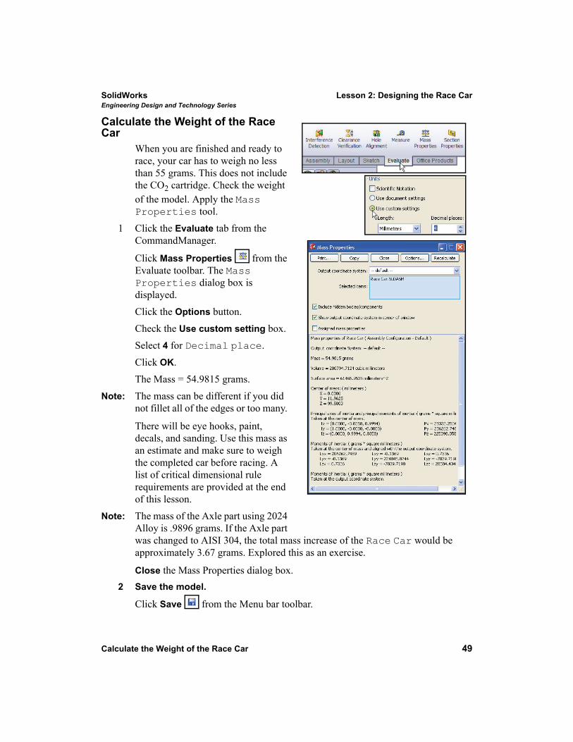
When you are finished and ready to race, your car has to weigh no less than 55 grams. This does not include the CO2 cartridge. Check the weight of the model. Apply the Mass Properties tool.
1 Click the Evaluate tab from the CommandManager.
Click Mass Properties from the Evaluate toolbar. The Mass Properties dialog box is displayed. Click the Options button.Check the Use custom setting box.Select 4 for Decimal place.Click OK.The Mass = 54.9815 grams.
Note: The mass can be different if you did not fillet all of the edges or too many.
There will be eye hooks, paint, decals, and sanding. Use this mass as an estimate and make sure to weigh the completed car before racing. A list of critical dimensional rule requirements are provided at the end of this lesson.
Note: The mass of the Axle part using 2024 Alloy is .9896 grams. If the Axle part was changed to AISI 304, the total mass increase of the Race Car would be approximately 3.67 grams. Explored this as an exercise.
Close the Mass Properties dialog box.2 Save the model.
Click Save from the Menu bar toolbar.
Lesson 2: Designing the Race Car SolidWorksEngineering Design and Technology Series
50 Calculate the Overall Length of the Race Car
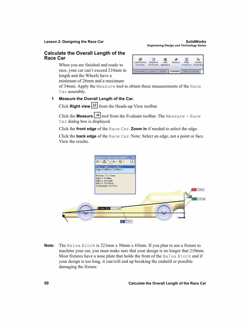
Calculate the Overall Length of the Race Car
When you are finished and ready to race, your car can’t exceed 210mm in length and the Wheels have a minimum of 26mm and a maximum of 34mm. Apply the Measure tool to obtain these measurements of the Race Car assembly.
1 Measure the Overall Length of the Car.
Click Right view from the Heads-up View toolbar.
Click the Measure tool from the Evaluate toolbar. The Measure - Race Car dialog box is displayed. Click the front edge of the Race Car. Zoom in if needed to select the edge.Click the back edge of the Race Car. Note: Select an edge, not a point or face. View the results.
Note: The Balsa Block is 223mm x 50mm x 65mm. If you plan to use a fixture to machine your car, you must make sure that your design is no longer that 210mm. Most fixtures have a nose plate that holds the front of the Balsa Block and if your design is too long, it can/will end up breaking the endmill or possible damaging the fixture.
SolidWorks Lesson 2: Designing the Race CarEngineering Design and Technology Series
Calculate the Overall Length of the Race Car 51
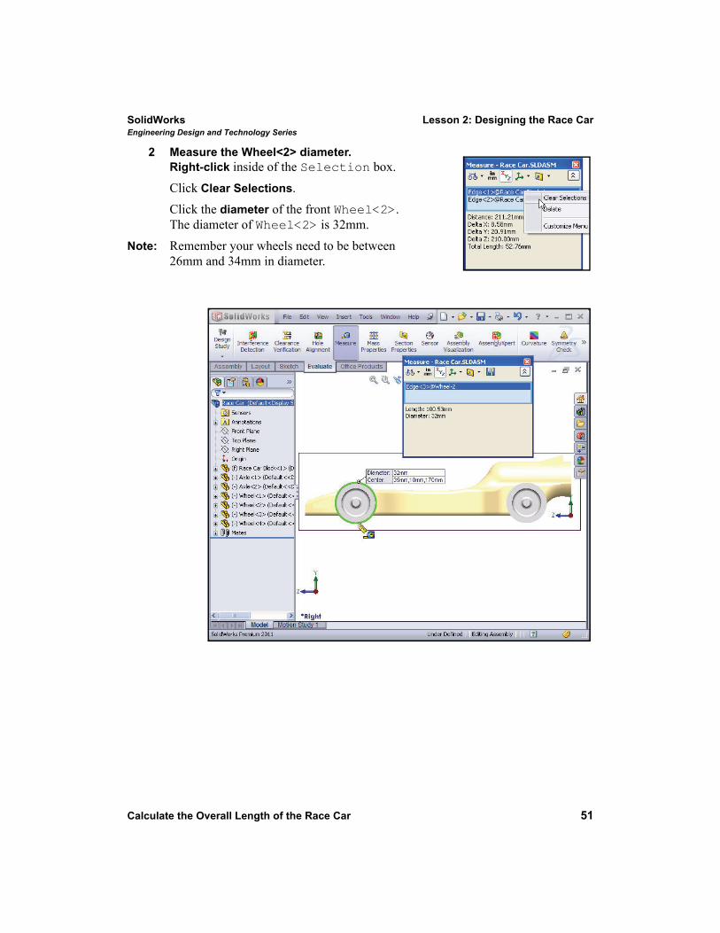
2 Measure the Wheel<2> diameter.Right-click inside of the Selection box.Click Clear Selections.Click the diameter of the front Wheel<2>. The diameter of Wheel<2> is 32mm.
Note: Remember your wheels need to be between 26mm and 34mm in diameter.
Lesson 2: Designing the Race Car SolidWorksEngineering Design and Technology Series
52 Calculate the Overall Length of the Race Car
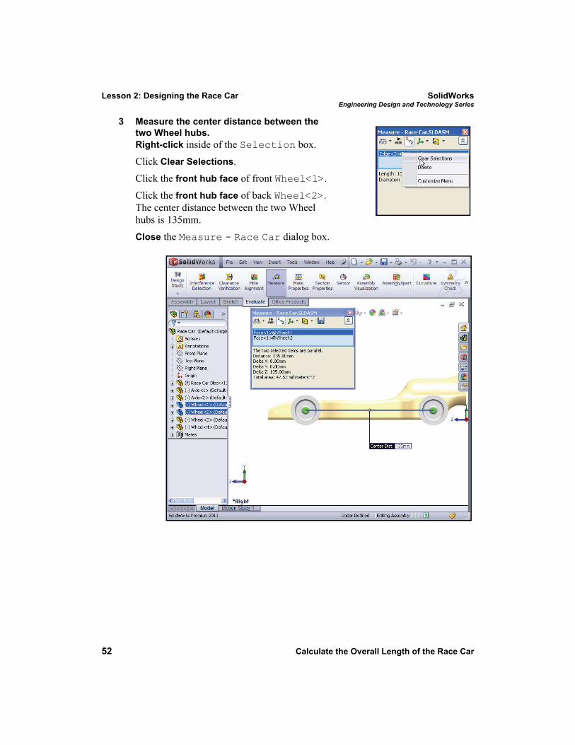
3 Measure the center distance between the two Wheel hubs.Right-click inside of the Selection box.Click Clear Selections.Click the front hub face of front Wheel<1>. Click the front hub face of back Wheel<2>. The center distance between the two Wheel hubs is 135mm. Close the Measure - Race Car dialog box.
SolidWorks Lesson 2: Designing the Race CarEngineering Design and Technology Series
Create an Exploded view 53
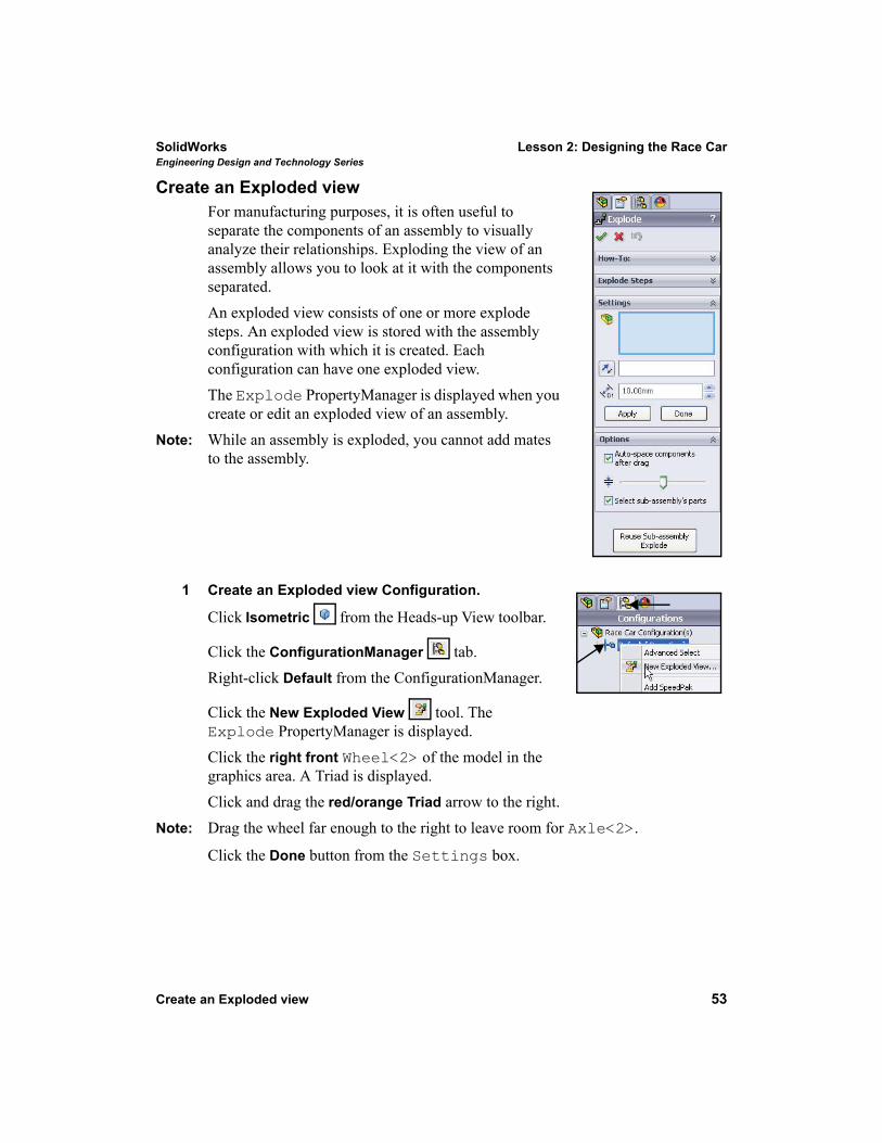
Create an Exploded viewFor manufacturing purposes, it is often useful to separate the components of an assembly to visually analyze their relationships. Exploding the view of an assembly allows you to look at it with the components separated. An exploded view consists of one or more explode steps. An exploded view is stored with the assembly configuration with which it is created. Each configuration can have one exploded view.The Explode PropertyManager is displayed when you create or edit an exploded view of an assembly.
Note: While an assembly is exploded, you cannot add mates to the assembly.
1 Create an Exploded view Configuration.
Click Isometric from the Heads-up View toolbar.
Click the ConfigurationManager tab.Right-click Default from the ConfigurationManager.
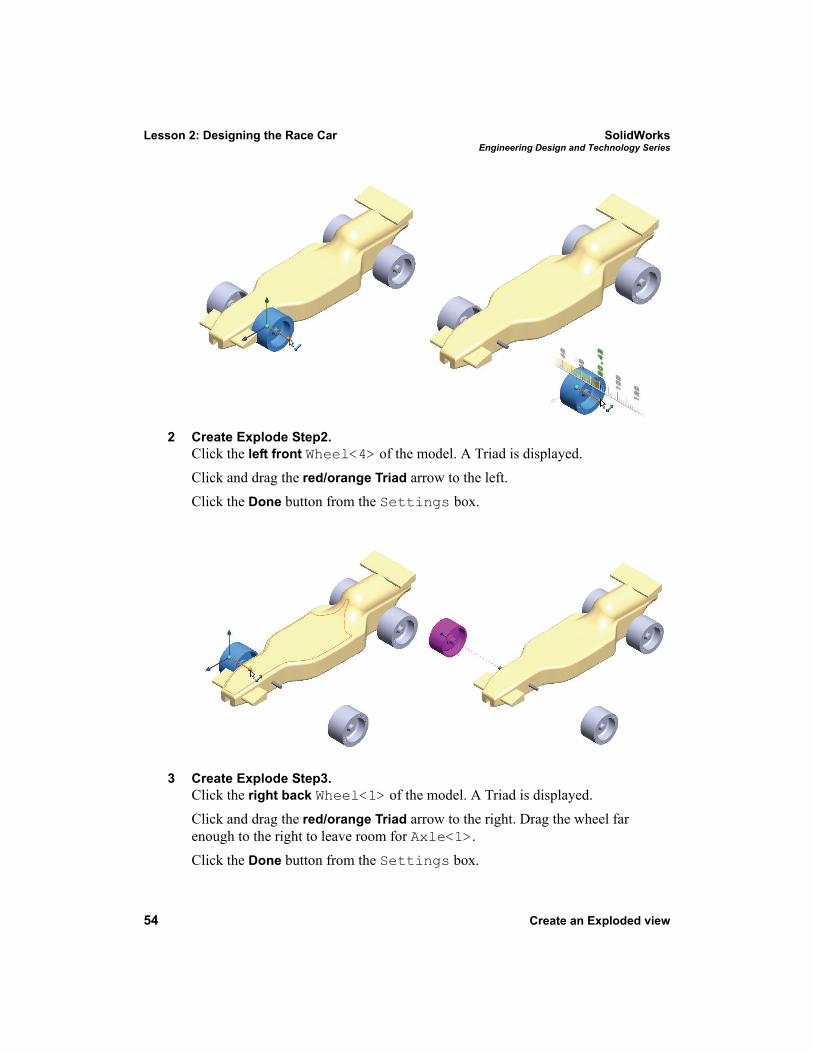
Click the New Exploded View tool. The Explode PropertyManager is displayed.Click the right front Wheel<2> of the model in the graphics area. A Triad is displayed.Click and drag the red/orange Triad arrow to the right.
Note: Drag the wheel far enough to the right to leave room for Axle<2>.
Click the Done button from the Settings box.
Lesson 2: Designing the Race Car SolidWorksEngineering Design and Technology Series
54 Create an Exploded view
2 Create Explode Step2.Click the left front Wheel<4> of the model. A Triad is displayed.Click and drag the red/orange Triad arrow to the left. Click the Done button from the Settings box.
3 Create Explode Step3.Click the right back Wheel<1> of the model. A Triad is displayed.Click and drag the red/orange Triad arrow to the right. Drag the wheel far enough to the right to leave room for Axle<1>. Click the Done button from the Settings box.
SolidWorks Lesson 2: Designing the Race CarEngineering Design and Technology Series
Create an Exploded view 55
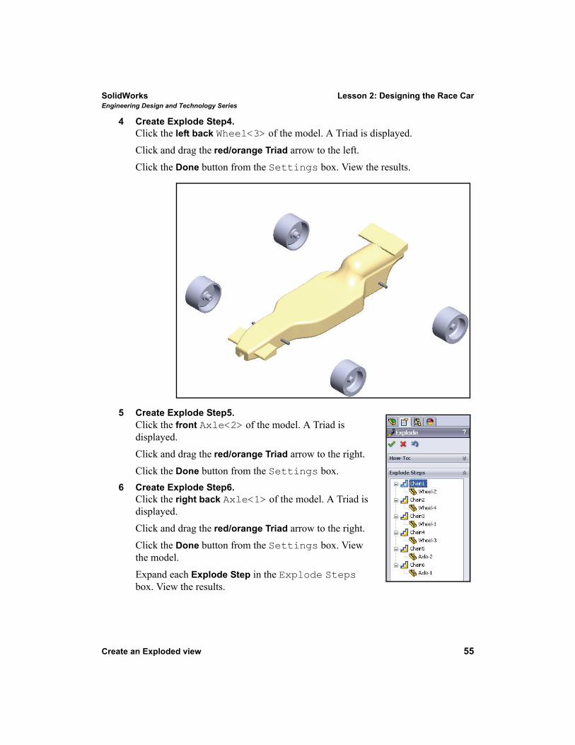
4 Create Explode Step4.Click the left back Wheel<3> of the model. A Triad is displayed.Click and drag the red/orange Triad arrow to the left. Click the Done button from the Settings box. View the results.
5 Create Explode Step5.Click the front Axle<2> of the model. A Triad is displayed.Click and drag the red/orange Triad arrow to the right.Click the Done button from the Settings box.
6 Create Explode Step6.Click the right back Axle<1> of the model. A Triad is displayed.Click and drag the red/orange Triad arrow to the right.Click the Done button from the Settings box. View the model.Expand each Explode Step in the Explode Steps box. View the results.
Lesson 2: Designing the Race Car SolidWorksEngineering Design and Technology Series
56 Create an Exploded view
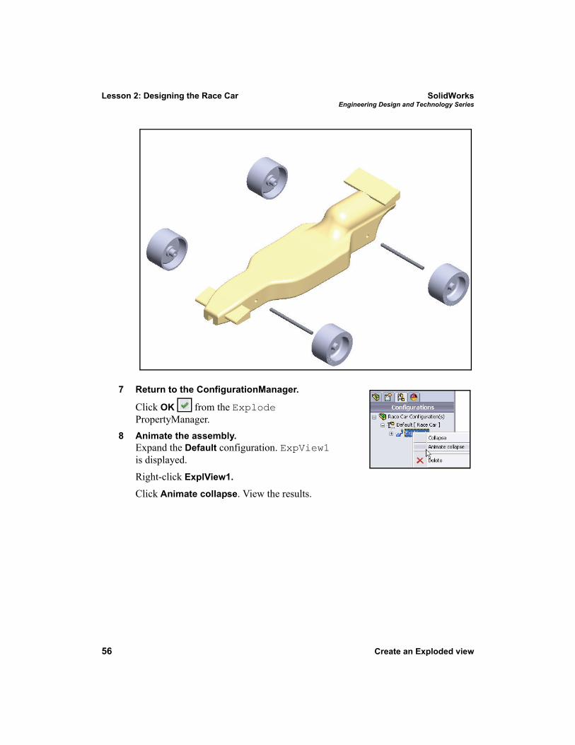
7 Return to the ConfigurationManager.
Click OK from the Explode PropertyManager.
8 Animate the assembly.Expand the Default configuration. ExpView1 is displayed.Right-click ExplView1.
Click Animate collapse. View the results.
SolidWorks Lesson 2: Designing the Race CarEngineering Design and Technology Series
Create an Exploded view 57
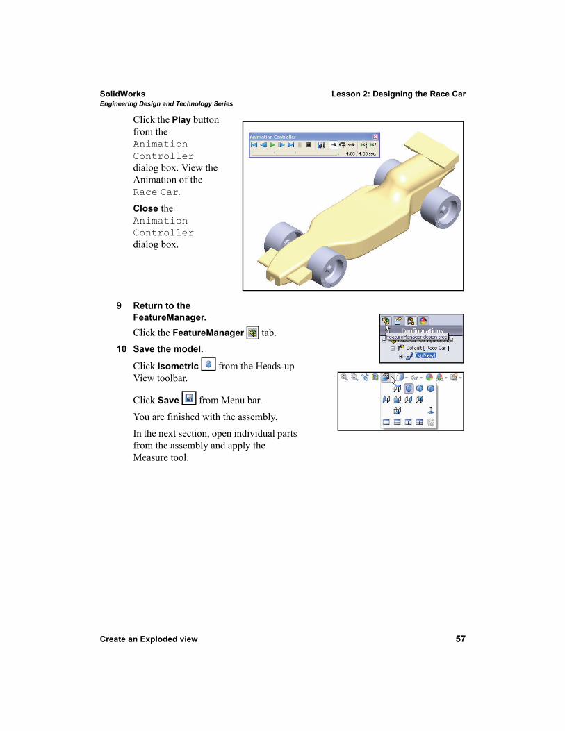
Click the Play button from the Animation Controller dialog box. View the Animation of the Race Car.Close the Animation Controller dialog box.
9 Return to the FeatureManager.Click the FeatureManager tab.
10 Save the model.
Click Isometric from the Heads-up View toolbar.
Click Save from Menu bar. You are finished with the assembly.In the next section, open individual parts from the assembly and apply the Measure tool.
Lesson 2: Designing the Race Car SolidWorksEngineering Design and Technology Series
58 Create an Exploded view
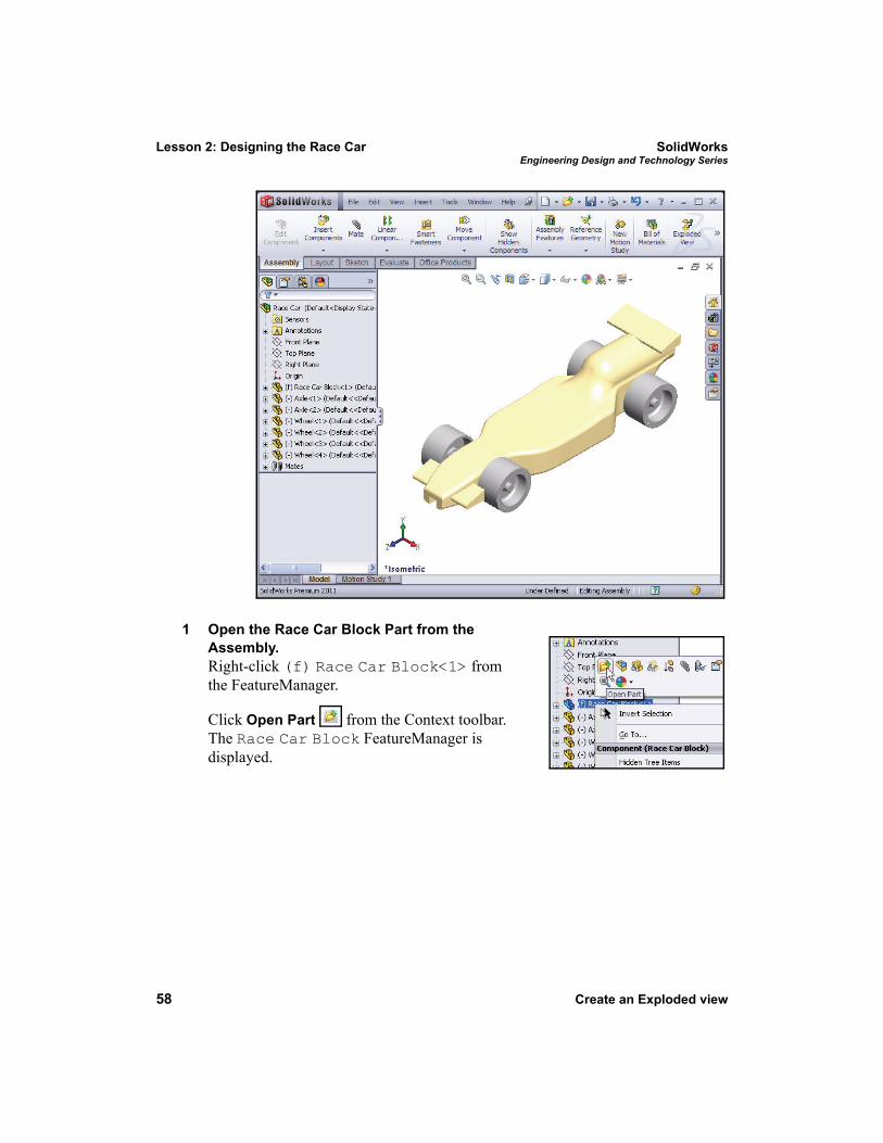
1 Open the Race Car Block Part from the Assembly.Right-click (f) Race Car Block<1> from the FeatureManager.
Click Open Part from the Context toolbar. The Race Car Block FeatureManager is displayed.
SolidWorks Lesson 2: Designing the Race CarEngineering Design and Technology Series
Create an Exploded view 59
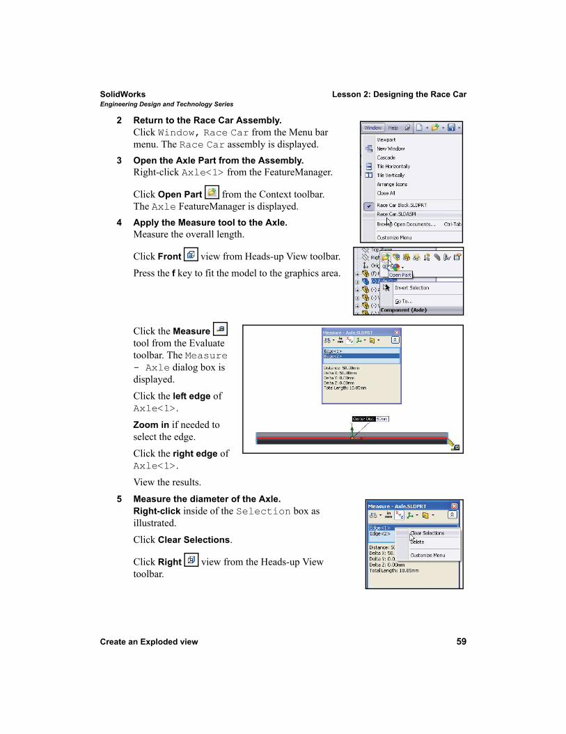
2 Return to the Race Car Assembly.Click Window, Race Car from the Menu bar menu. The Race Car assembly is displayed.
3 Open the Axle Part from the Assembly.Right-click Axle<1> from the FeatureManager.
Click Open Part from the Context toolbar. The Axle FeatureManager is displayed.
4 Apply the Measure tool to the Axle.Measure the overall length.
Click Front view from Heads-up View toolbar.Press the f key to fit the model to the graphics area.
Click the Measure tool from the Evaluate toolbar. The Measure - Axle dialog box is displayed. Click the left edge of Axle<1>. Zoom in if needed to select the edge.Click the right edge of Axle<1>. View the results.
5 Measure the diameter of the Axle.Right-click inside of the Selection box as illustrated.Click Clear Selections.
Click Right view from the Heads-up View toolbar.
Lesson 2: Designing the Race Car SolidWorksEngineering Design and Technology Series
60 Create an Exploded view
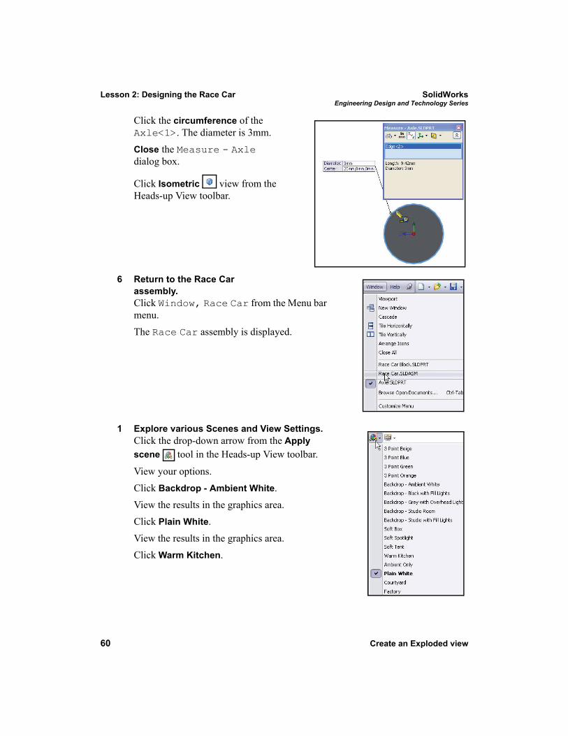
Click the circumference of the Axle<1>. The diameter is 3mm. Close the Measure - Axle dialog box.
Click Isometric view from the Heads-up View toolbar.
6 Return to the Race Car assembly.Click Window, Race Car from the Menu bar menu. The Race Car assembly is displayed.
1 Explore various Scenes and View Settings.Click the drop-down arrow from the Apply scene tool in the Heads-up View toolbar.
View your options.Click Backdrop - Ambient White. View the results in the graphics area.Click Plain White.View the results in the graphics area.Click Warm Kitchen.
SolidWorks Lesson 2: Designing the Race CarEngineering Design and Technology Series
Create an Exploded view 61
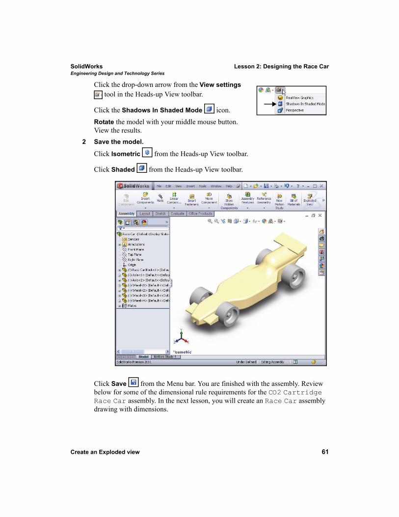
Click the drop-down arrow from the View settings tool in the Heads-up View toolbar.
Click the Shadows In Shaded Mode icon. Rotate the model with your middle mouse button. View the results.
2 Save the model.
Click Isometric from the Heads-up View toolbar.
Click Shaded from the Heads-up View toolbar.
Click Save from the Menu bar. You are finished with the assembly. Review below for some of the dimensional rule requirements for the CO2 Cartridge Race Car assembly. In the next lesson, you will create an Race Car assembly drawing with dimensions.
Lesson 2: Designing the Race Car SolidWorksEngineering Design and Technology Series
62 Race Car Dimensional Requirements
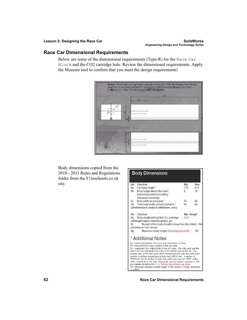
Race Car Dimensional RequirementsBelow are some of the dimensional requirements (Type-R) for the Race Car Block and the CO2 cartridge hole. Review the dimensional requirements. Apply the Measure tool to confirm that you meet the design requirements!
Body dimensions copied from the 2010 - 2011 Rules and Regulations folder from the F1inschools.co.uk site.
SolidWorks Lesson 2: Designing the Race CarEngineering Design and Technology Series
Race Car Dimensional Requirements 63
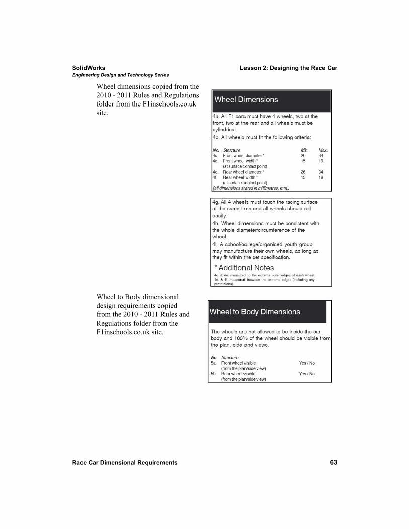
Wheel dimensions copied from the 2010 - 2011 Rules and Regulations folder from the F1inschools.co.uk site.
Wheel to Body dimensional design requirements copied from the 2010 - 2011 Rules and Regulations folder from the F1inschools.co.uk site.
Lesson 2: Designing the Race Car SolidWorksEngineering Design and Technology Series
64 Race Car Dimensional Requirements
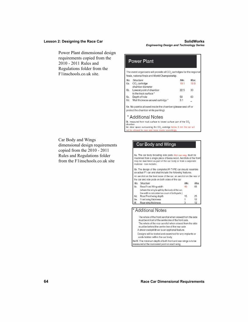
Power Plant dimensional design requirements copied from the 2010 - 2011 Rules and Regulations folder from the F1inschools.co.uk site.
Car Body and Wings dimensional design requirements copied from the 2010 - 2011 Rules and Regulations folder from the F1inschools.co.uk site