Rac08 Workbook Metric Final -Sept07 update -...
323
Revit Architecture Building Information Modeling with Revit Architecture Student Workbook
Transcript of Rac08 Workbook Metric Final -Sept07 update -...

Revit Architecture
Building Information Modeling with Revit Architecture
Student Workbook

Contents
Introduction .......................................................................................................................................................................................................................................... 5 Unit 1 ................................................................................................................................................................................................................................................... 9
Theory: CAD Versus BIM ................................................................................................................................................................................................................ 9 Revit Architecture: Introduction, Interface, and Sketching ............................................................................................................................................................... 9
Exercise 1A: Interface and Terminology ....................................................................................................................................................................................... 9 Exercise 1B: Starting a New Project ........................................................................................................................................................................................... 14
Unit 2 ................................................................................................................................................................................................................................................. 31 Theory: Objects ............................................................................................................................................................................................................................. 31 Revit Architecture: Walls, Floors, and Ceilings .............................................................................................................................................................................. 31
Unit 3 ................................................................................................................................................................................................................................................. 50 Theory: Families and Nested Families .......................................................................................................................................................................................... 50 Revit Architecture: Editing Types .................................................................................................................................................................................................. 50
Unit 4 ................................................................................................................................................................................................................................................. 61 Theory: Parameters....................................................................................................................................................................................................................... 61 Revit Architecture: Dimensions, Doors, and Windows ................................................................................................................................................................... 61
Unit 5 ................................................................................................................................................................................................................................................. 69 Theory: Representations ............................................................................................................................................................................................................... 69 Revit Architecture: Views, Visibility, and Sheets ............................................................................................................................................................................ 69
Exercise 5A: Sections, Views, and Sheets ................................................................................................................................................................................. 69 Exercise 5B: Display Control of Materials ................................................................................................................................................................................... 80 Exercise 5C: Fine-Tuning Wall Cleanup and Display ................................................................................................................................................................. 85 Exercise 5D: Sun and Shadow Studies ...................................................................................................................................................................................... 93 Exercise 5E: Importing a Revit Architecture Model into Autodesk 3ds Max ................................................................................................................................ 97
Unit 6 ............................................................................................................................................................................................................................................... 104 Theory: Design Constraints ......................................................................................................................................................................................................... 104 Revit Architecture: Levels, Reference Planes, and Grids ............................................................................................................................................................ 104
Unit 7 ............................................................................................................................................................................................................................................... 119 Theory: Design Information Organization .................................................................................................................................................................................... 119 Revit Architecture: Components, Groups, Categories, and Subcategories ................................................................................................................................. 119
Exercise 7A: View Templates, Categories, and Subcategories ................................................................................................................................................ 119 Exercise 7B: Group Basics ....................................................................................................................................................................................................... 129 Exercise 7C: Groups and Links ................................................................................................................................................................................................ 138 Exercise 7D: Dependent Annotation views ............................................................................................................................................................................... 143
Unit 8 ............................................................................................................................................................................................................................................... 148 Theory: Domain-Specific Knowledge .......................................................................................................................................................................................... 148 Revit Architecture: Roofs ............................................................................................................................................................................................................. 148
Unit 9 ............................................................................................................................................................................................................................................... 157 Theory: Delaying Specificity ........................................................................................................................................................................................................ 157 Revit Architecture: Massing ......................................................................................................................................................................................................... 157

Revit Architecture Student Workbook Autodesk
3
Exercise 9A: Mass Components and Building Maker ............................................................................................................................................................... 157 Exercise 9B: Importing SketchUp Files .................................................................................................................................................................................... 171
Unit 10 ............................................................................................................................................................................................................................................. 176 Theory: Component Design ........................................................................................................................................................................................................ 176 Revit Architecture: Family Editor ................................................................................................................................................................................................. 176
Unit 11 ............................................................................................................................................................................................................................................. 196 Theory: Propagation of Constraints ............................................................................................................................................................................................. 196 Revit Architecture: Alignment, Locking, and Constraints ............................................................................................................................................................. 196
Exercise 11A: In-Place Family Editing and Symbolic Line Representation ............................................................................................................................... 197 Exercise 11B: Material Parameters .......................................................................................................................................................................................... 207 Exercise 11C: Visibility Parameters .......................................................................................................................................................................................... 209 Exercise 11D: Nested Families ................................................................................................................................................................................................. 215 Exercise 11E: Subcategories and Families .............................................................................................................................................................................. 228
Unit 12 ............................................................................................................................................................................................................................................. 236 Theory: Interdependencies .......................................................................................................................................................................................................... 236 Revit Architecture: Site ................................................................................................................................................................................................................ 236
Exercise 12A: Importing AutoCAD Drawings ............................................................................................................................................................................ 236 Exercise 12B: Importing Revit Architecture Projects ................................................................................................................................................................. 240 Exercise 12C: Site Tools .......................................................................................................................................................................................................... 244 Exercise 12D: Exporting AutoCAD Drawings ........................................................................................................................................................................... 251
Unit 14 ............................................................................................................................................................................................................................................. 256 Theory: Detail .............................................................................................................................................................................................................................. 256 Revit Architecture: Drafting and Linework ................................................................................................................................................................................... 256
Unit 16 ............................................................................................................................................................................................................................................. 261 Theory: Is Architecture Engineering? .......................................................................................................................................................................................... 261 Revit Architecture: Formulas ....................................................................................................................................................................................................... 261
Unit 17 ............................................................................................................................................................................................................................................. 267 Theory: Databases ...................................................................................................................................................................................................................... 267 Revit Architecture: Databases ..................................................................................................................................................................................................... 267
Unit 18 ............................................................................................................................................................................................................................................. 270 Theory: Schedules, Tables, and Legends ................................................................................................................................................................................... 270 Revit Architecture: Tags, Schedules and Legends ...................................................................................................................................................................... 270
Exercise 18A: Door Schedules ................................................................................................................................................................................................. 270 Exercise 18B: Room Objects, Schedules and Tags ................................................................................................................................................................. 282 Exercise 18C: Calculated Values for Rooms ............................................................................................................................................................................ 293 Exercise 18D: Room Schedule Keys ........................................................................................................................................................................................ 296 Exercise 18E: Color Scheme .................................................................................................................................................................................................... 299 Exercise 18F: Legends ............................................................................................................................................................................................................. 304 Exercise 18G: Material Takeoffs ............................................................................................................................................................................................... 307
Unit 19 ............................................................................................................................................................................................................................................. 309 Theory: Time ............................................................................................................................................................................................................................... 309 Revit Architecture: Phasing ......................................................................................................................................................................................................... 309
Unit 20 ............................................................................................................................................................................................................................................. 315

Revit Architecture Student Workbook Autodesk
4
Theory: Variation ......................................................................................................................................................................................................................... 315 Revit Architecture: Options .......................................................................................................................................................................................................... 315

Introduction This student workbook contains exercises that clarify in a practical way the concepts explained in the Building Information Modeling with Revit® Architecture Lecture Notes by Simon Greenwold. The exercises cover the basic principles of the Revit Architecture technology and the building information modeling (BIM) approach. For more training information, see the official Revit Architecture training manuals and the tutorials available from the Help menu. This workbook explains the different functionalities through various exercises, but the emphasis is on the workflow rather than on the tools themselves. Because this workbook is a companion to the lecture notes, it is organized roughly to correspond to the organization of that document. The difficulty of the exercises increases as you proceed through the units, so it is recommended that you do them in sequence. However, each exercise has a corresponding starting point Revit Architecture file and can be completed independently. Files representing the ending point of each exercise have also been provided in the Completed folder along with the rest of the data sets and can be used to check your work. Because each exercise can stand alone, you can work through them in any manner you see fit. The following table organizes the units to give you an idea where you might find information particular to a given operational task.
Interoperability Design Model Visualization Documentation Unit 5: Using Revit with 3ds Max
Unit 6: Design Constraints
Unit 1: Walls, doors, windows
Unit 1: Navigation, Working with Views, Camera
Unit 5: Views
Unit 9: Importing SketchUp® files
Unit 7: Groups Unit 2: Object Properties
Unit 5: Shade/Shadow Unit 5: Linework Control
Unit 12: Importing and exporting DWG™ Format Files Importing Revit Architecture Files
Unit 9: Massing Unit 3: More Walls, Doors, Windows
Unit 5: Solar Studies: Creating Sheets
Unit 7: View Templates
Unit 17: External Databases
Unit 9: SketchUp Link Unit 6: Extruded (with Curve) Roofs
Unit 11: Family Materials Unit 7: Graphic Overrides
Unit 12: Site Unit 8: More Roof Tricks plus Gutters, Soffits
Unit 18: Color Fills Unit 14: Drafting/ Linework
Unit 19: Phasing Unit 10: Family Components
Unit 5: Using Revit with 3ds Max
Unit 18: Schedules, Legends, and Material Takeoffs
Unit 20: Design Options Unit 11: Family Constraints and Advanced Parameters, Nesting Families
Unit 16: Formulas in Families

Revit Architecture Student Workbook Autodesk
6
The workbook is structured in a three-column format (see following image): The first column contains an explanation of all steps necessary to complete an exercise.
The middle column contains the images that clarify visually the tasks to accomplish.
The third column contains notes on the features and tools that are being used, as well as a few helpful tips.
We have prepared the following data for you: • Workbook (this document). • Workbook data sets (placed in a folder that contains all necessary files, families, and the template prepared for your use). Before starting the exercises, change the following settings to simplify use of this workbook and provide faster access to the data sets. These steps create a library using the Revit Architecture Option settings. A library is a shortcut that appears in any Revit Architecture dialog box that asks you to browse for a file. This includes the Open and Save As commands as well as others. Create a Library (Shortcut) to the
Workbook Files
1 Copy the provided Workbook Data Sets folder onto your desktop.
You can copy the data sets from the provided CD or download to any location you choose.

Revit Architecture Student Workbook Autodesk
7
2 Open Revit Architecture.
3 On the Settings menu, click Options.
4 Click the File Locations tab.
5 Click the Add Library button.
6 Click the New Library 1 name field. Rename the newly created New Library 1 to Workbook Data Sets.
7 Click in the blank Library Path field next to it, and then click the Browse icon at the far right of the row.
8 Browse to the path where you saved the data sets. Click OK.
9 Click the Workbook Data Sets field,
and using the upper flash sign move it up to the first row.

Revit Architecture Student Workbook Autodesk
8
Now each time you go to the File menu to open or save, you see the folder in the Browse window on the left so you can access it quickly.
Note: Exercises for some lecture note units are not available here and in some cases have been grouped into a single exercise. The reason lies in the workflow approach that does not meet specific feature training requirements. For more information, see the Autodesk Official Training Courseware and the help file. We hope you enjoy learning the principles of Revit Architecture and the BIM approach.
Have fun!

Unit 1 Theory: CAD Versus BIM
Revit Architecture: Introduction, Interface, and Sketching This unit has two exercises. The first is an introduction to the terminology of the Revit Architecture interface, and the second exercise creates a new project, using a template.
Exercise 1A: Interface and Terminology This first exercise is provided for anyone new to the Revit Architecture environment. This is not an exercise as much as an introduction to the locations and names of the various Revit Architecture tools and functions that are used throughout the workbook. Revit Architecture Environment
When you open Revit Architecture, you see a window that looks like the image shown here. When working through the workbook, you are asked to perform functions such as: • Using the menus. • Using the design bar tools to add
things to the project. • Using the toolbar tools to modify
things with Copy, Move, Align, and Split tools.
• Using the project browser to
change views or set views current.
Menu System The menu system is like most Microsoft® Windows®–compliant software. Click the menu item to view a list.

Revit Architecture Student Workbook Autodesk
10
Many of the menu functions have flyout functions as well. Within the workbook, any menu flyouts are noted with a “>” character. Example: On the File menu, click New > Project. This format indicates that you use the File menu to select New and then Project.
Toolbars Again, as most Windows programs, Revit Architecture includes a series of tools on toolbars immediately below the menu system. In Revit Architecture these toolbars provide access to common functions such as New, Save, and Print as well as modify functions such as Copy, Move, and Trim.
Design Bar The design bar is the area on the far left of the Revit Architecture drawing window. The design bar contains most of the tools to add components such as walls, doors, windows, desks, chairs, and so forth as well as schedules, tags, and section or elevation marks.

Revit Architecture Student Workbook Autodesk
11
The design bar has many tabs. Each tab (Basics, View, Modeling, and more) appears as a rectangle with the title on it. Each tab contains its own set of tools. Change to a different tab by left-clicking the tab.
Within the workbook, exercise steps tell you which tab to find the tool on. Example: On the Basics design bar, click Door and place two doors M_Single Flush 0864 x 2134 mm.
Options Bar The options bar is where you adjust properties of the objects as you are drawing them. You can also use the options bar to modify an object’s properties after it is in the project. The options bar can be confusing to some new users. Appearing immediately below the toolbar, it may look like just another toolbar. This image shows the options bar while adding a wall.
Revit Architecture Student Workbook Autodesk
12
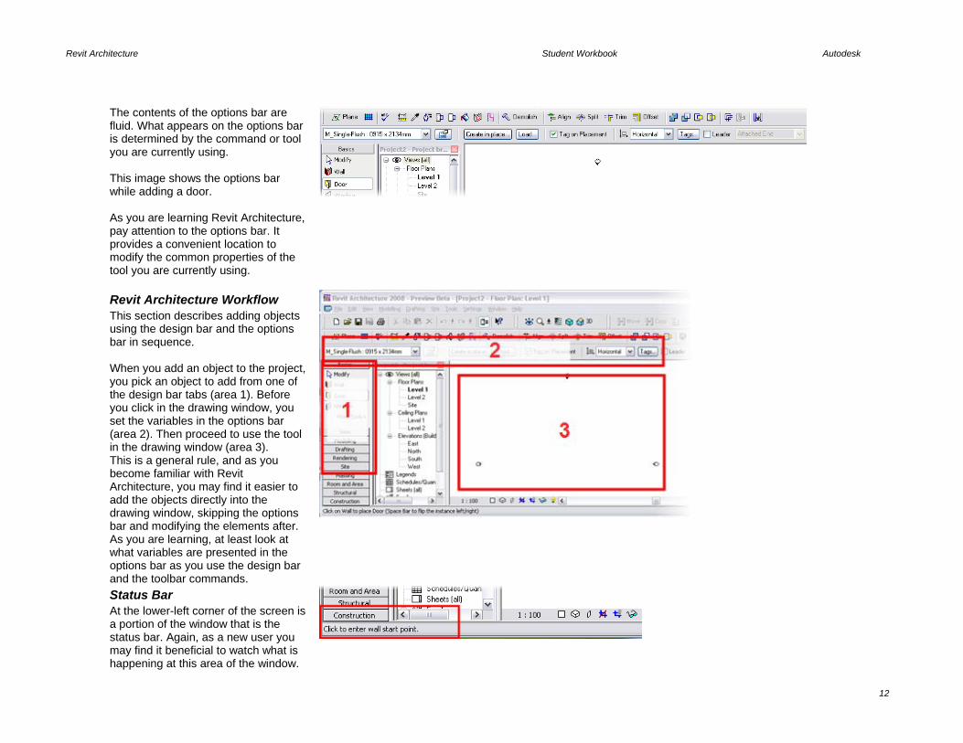
The contents of the options bar are fluid. What appears on the options bar is determined by the command or tool you are currently using. This image shows the options bar while adding a door. As you are learning Revit Architecture, pay attention to the options bar. It provides a convenient location to modify the common properties of the tool you are currently using.
Revit Architecture Workflow This section describes adding objects using the design bar and the options bar in sequence. When you add an object to the project, you pick an object to add from one of the design bar tabs (area 1). Before you click in the drawing window, you set the variables in the options bar (area 2). Then proceed to use the tool in the drawing window (area 3). This is a general rule, and as you become familiar with Revit Architecture, you may find it easier to add the objects directly into the drawing window, skipping the options bar and modifying the elements after. As you are learning, at least look at what variables are presented in the options bar as you use the design bar and the toolbar commands.
Status Bar At the lower-left corner of the screen is a portion of the window that is the status bar. Again, as a new user you may find it beneficial to watch what is happening at this area of the window.

Revit Architecture Student Workbook Autodesk
13
The status bar serves two purposes.
The first function is to alert you to what you do next. This works while you are adding objects such as a wall, as well as when you are using the other tools such as Copy, Trim, or Align. The second function is to alert you to what you are selecting. If you are not in a command and you hover your cursor over an object, the status bar displays what that object is. If you have several objects in the same location, you can use the TAB key to cycle through the objects at that location.
Workspace View Bar The Drawing View menu is also located near the bottom-left side of the screen just below the drawing area. The Drawing View menu provides access to some of the view’s properties such as intended plotting scale, detail level, and the Hide/Isolate Objects in Current View functions.
Project Browser The project browser is located between the design bar and the drawing area.

Revit Architecture Student Workbook Autodesk
14
The project browser is the navigation control of the project. Each view of the project is listed in a tree organization. You access these views by double-clicking the view name. Below the views are listed the families (building component definitions) that are currently loaded into the project for you to use.
Exercise 1B: Starting a New Project In this unit you start a new project using a template. Templates are prepared drawing files that contain data according to office or project standards, helping to ensure that all team members working on the same project are using the same objects and standards. You can create these templates on your own, according to your office or project requirements. Create a New Project from the
Provided Template
In this exercise you add walls, doors, windows, floor, and roof to create a simple building that you will work on in units 2–5.
Exercise Start Exercise End
1 On the File menu, click New >

Revit Architecture Student Workbook Autodesk
15
Project.
2 Click the Browse button. Click the Revit Workbook library shortcut icon.
3 Select Workbook Metric Template.rte.
In the default folder are templates for commercial and residential, as well as other specialized templates you can choose to start from. Each of these templates has unique families, views, and possibly sheets already loaded for you to work with.
4 Click Open. Click OK.
Revit Architecture Student Workbook Autodesk
16
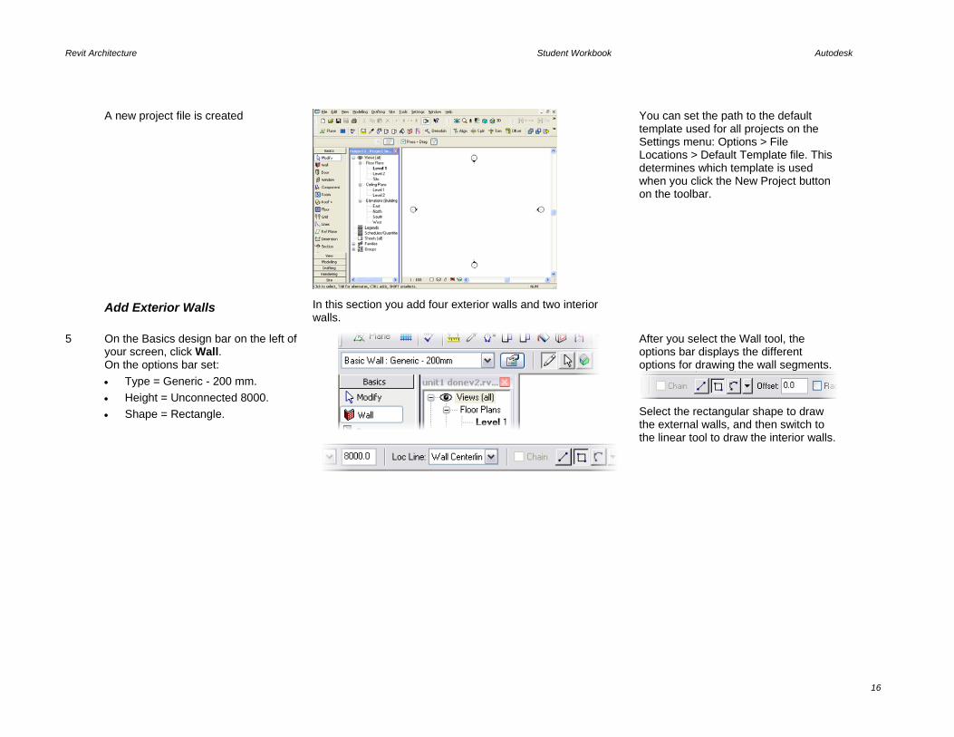
A new project file is created
You can set the path to the default template used for all projects on the Settings menu: Options > File Locations > Default Template file. This determines which template is used when you click the New Project button on the toolbar.
Add Exterior Walls In this section you add four exterior walls and two interior walls.
5 On the Basics design bar on the left of your screen, click Wall. On the options bar set: • Type = Generic - 200 mm. • Height = Unconnected 8000. • Shape = Rectangle.
After you select the Wall tool, the options bar displays the different options for drawing the wall segments.
Select the rectangular shape to draw the external walls, and then switch to the linear tool to draw the interior walls.

Revit Architecture Student Workbook Autodesk
17
6 To draw the four exterior walls, left-click at a point within the four elevation markers in the drawing area. Holding the mouse button, drag your cursor to the lower right and release the mouse button. The rectangle should be about 12 x 10 m but does not have to be exact at this point.
Draw the Interior Walls
7 Without exiting the Wall command, in the options bar set: • Type = Interior Blockwork 100. • Height = Unconnected 8000. • Shape = Line. • Clear the Chain check box.
8 Draw two interior walls, as shown in the image.
Add Doors and Windows In this section you add doors and windows to the project. There are some door definitions in the project. You use the Load function to add more definitions.

Revit Architecture Student Workbook Autodesk
18
9 On the Basics design bar, click Door and place two doors M_Single Flush 0864 x 2134 mm, as shown in the image.
As you add these two doors, press SPACEBAR before you select a point to flip the swing before the door is placed.
10 With the Door tool still active, on the options bar, click Load.
Many other door types are installed with the software but not available in the general template you started with. When you load from library, you are bringing in a family of doors and all its types.
11 In the Open dialog box: • Click the Metric Library shortcut. • Browse to the Doors folder. • Select the M_Double Flush door
type. • Click Open.
12 Change the door type on the options bar to Double-Flush. Position an 1830 x 1981 door on the left wall, as shown in the image.
13 Press ESC twice to exit the command. To end a command in Revit Architecture, either press ESC two times, or right-click and then click

Revit Architecture Student Workbook Autodesk
19
Cancel two times.
14 To change the swing direction of a door: • Select the door. • Click the flip arrows that appear.
The horizontal arrows mirror the door along the wall it is positioned on. Both vertical and horizontal arrow symbols appear in doors, windows, furniture components, and in all families that can be mirrored or reversed without changing their geometry or function.
15 On the Basics design bar, click Windows.
Windows and doors are tagged automatically if Tag on Placement is selected on the options bar. To avoid automatic tagging, clear the option.
16 On the options bar, select M_Fixed 0915 x 1220 mm.
17 Position some windows on the exterior walls, as shown in the image, by clicking the exterior walls.
The tags that appear when placing the components are set on the Settings menu: Annotations > Loaded Tags.
18 Right-click anywhere in the drawing window. Click Cancel. Repeat this again to exit the command.
In the next section you add a floor to the project.
When you add floors you use Sketch mode to draw linework that defines the edges of the floor slab.
Sketch Mode Introduction Before you start drawing the floor, read this overview of Sketch mode. A wall is a linear element and can be defined by two points in the drawing window. Doors and windows have discrete geometry, and this geometry is stored in the family definitions either within the project or outside the project as RFA files that you load as needed.
The design bar changes to the Sketch design bar with tools to help you draw the series of 2D sketch lines. When you end Sketch mode, the linework you have drawn is converted to the the building component and the design bar returns to its normal state. You use Sketch mode for many things in Revit Architecture. When creating floors, roofs, railings, stairs, solids, and voids, you use Sketch mode to establish the geometry of the building component.
Sketch mode lines have a few simple rules: • Sketch lines must not overlap. • Sketch lines must usually form a
continous shape without breaks or gaps in the linework.
• Sketch lines must not form T intersections.
Each of the different building

Revit Architecture Student Workbook Autodesk
20
Some building components such as floors and roofs cannot be stored with predetermined geometry. For these elements, you draw lines to establish the base geometry. Revit Architecture then uses these lines as the base geometry to create the building component. When you pick a tool from the design bar that depends on a series of sketch lines, the tool starts Sketch mode. While you are in Sketch mode, you draw a series of 2D lines.
components that you create with Sketch mode varies slightly in its requirements for its Sketch mode linework.
Tip Tab to Select Chain of Walls or Lines To select all the exterior walls or a connected chain of lines in Revit Architecture, you can use the “Hover-TAB-click” method. This method enables you to select the connected (or chained) set of walls with one click rather than clicking each wall separately.
Hover cursor TAB (press the TAB key) then left-click to select all the connected walls or lines. (note the tab key is just pressed and released, not held down like the shift and ctrl keys)
Add a Floor
19 On the Basics design bar, click Floor. You are now in Sketch mode, and the design bar has changed. The default method for creating floors is by selecting existing walls (Pick Walls).
You can draw the desired shape of your object (floor in this case) using the Lines tool, but often it is much faster and easier to accept the default proposed mode. The Pick Walls function automatically recognizes the boundary of the connected walls and generates a closed loop of lines that represent the shape of the floor.

Revit Architecture Student Workbook Autodesk
21
The side of the wall your cursor is on when you select a wall determines which side of the wall the sketch line is placed on. When you use Pick Walls to define your sketch, Revit Architecture snaps either to the exterior/interior faces of the wall or to its structural core layer, as set on the options bar.
20 Hover-TAB-click to select all connected walls at once: • Place the cursor over the inside
edge of one of the exterior walls (without clicking).
• Press TAB to highlight all four walls.
• Left-click to select the highlighted walls as the floor boundary. Make sure you click the interior side of the walls.
When you click the mouse button, the software reads the geometry into the command and creates a magenta sketch line at each wall.
21 On the design bar, click Finish Sketch to accept the floor sketch.
You can reenter Sketch mode any time after designing the component by selecting the component and clicking the Edit button on the options bar.

Revit Architecture Student Workbook Autodesk
22
22 Open a 3D view by clicking the 3D view icon on the toolbar.
3D View Navigation
23 Rotate the model in the 3D view by pressing SHIFT and the middle button of the mouse at the same time, and then move the mouse.
The cursor changes to the 3D rotate cursor.
Alternatively, click the icon on the View toolbar to open the Dynamic View dialog box. Then select Spin mode.
Model Graphic Style
You can use several different methods to change from Shade mode to Wireframe to Hidden mode.

Revit Architecture Student Workbook Autodesk
23
24 Model graphic style by keyboard shortcut: Press the SD keys (in sequence) to activate a shaded view.
The other keyboard shortcuts for graphic style are as follows: • WF = Wireframe. • HL = Hidden Line. • AG = Advanced Model Graphics. You can customize keyboard shortcuts by editing the keyboardshortcuts.txt file in the program folder.
25 Model graphic style by view properties: Right-click the view. Click View Properties. In the Properties dialog box, change the Model Graphics Style to Wireframe.
Like any wall or door, the view itself has properties. The properties page of a view controls many aspects of how the model is represented.
26 Model graphic style by Workspace View toolbar: Click the model graphics tool at the bottom-left of the workspace. Click Shaded with Edges.
Modify Position of Components with Temporary Dimensions

Revit Architecture Student Workbook Autodesk
24
27 In the project browser, open Floor Plans Level 1 again by double-clicking Floor Plans: Level 1. Select the left exterior wall. A temporary dimension appears.
The temporary dimension may not have the witness lines in the location you want. Drag the middle square grip on a temporary dimension line to a new location.
28 Drag the square middle grip to the right exterior wall.
29 Click the dimension text. Type 12000 to change the building width to 12 meters. Repeat to make the North-South dimension 10000.
Revit Architecture uses real-world units: you can set them to metric or imperial. You can access the dialog box for setting units by clicking Units on the Settings menu..
30 Select the interior wall. Use the temporary dimensions to set the interior vertical wall to 6000 from one of the end walls.
Notice that you have just defined a new position of the wall, but all other components adjusted accordingly. Temporary dimensions appear whenever you select a component. Edit these dimensions on the fly by clicking the text and typing the desired value. You can transform these dimensions into permanent dimensions by clicking the icon that appears below the dimension line.
Revit Architecture Student Workbook Autodesk
25
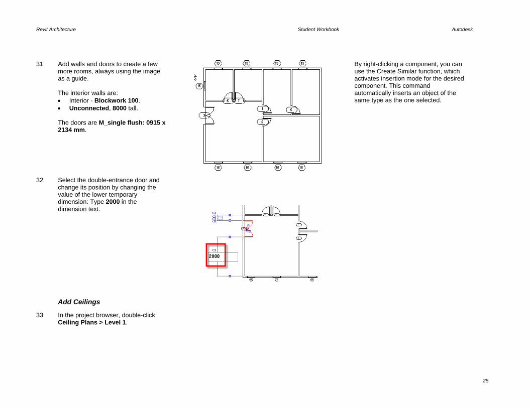
31 Add walls and doors to create a few more rooms, always using the image as a guide. The interior walls are: • Interior - Blockwork 100. • Unconnected, 8000 tall. The doors are M_single flush: 0915 x 2134 mm.
By right-clicking a component, you can use the Create Similar function, which activates insertion mode for the desired component. This command automatically inserts an object of the same type as the one selected.
32 Select the double-entrance door and change its position by changing the value of the lower temporary dimension: Type 2000 in the dimension text.
Add Ceilings
33 In the project browser, double-click Ceiling Plans > Level 1.

Revit Architecture Student Workbook Autodesk
26
34 Add ceilings to the rooms: • On the Modeling design bar, click
Ceiling. • On the options bar set ceiling type:
Compound Ceiling: 600 x 600 mm grid.
• Click once inside each room to automatically generate the ceilings.
Although added with just a single click, ceilings, like floors, are also sketch based. The Autogenerate tool is helpful, but if you need to change the shape, you must select the ceiling and click Edit on the options bar.
Selection Tip Hold your cursor over the object, and press TAB: • Sometimes selecting objects that
are colinear with other objects can be difficult.
• Hold your cursor over the edge of a ceiling (which is also the same location as a wall).
• Press TAB a couple times to cycle through the objects that are at the cursor location.
Anything that you select with a left mouse-click is available as a tooltip and at the lower-left corner of the window at the status bar.
Add a Roof You can create roofs by footprint or by extrusion. This exercise walks you through creating a roof by footprint. A later unit illustrates roof by extrusion.
35 In the project browser, open Floor Plans > Level 2.

Revit Architecture Student Workbook Autodesk
27
36 On the Modeling design bar, click Roof > By Footprint. You are in Sketch mode. The default Sketch mode is Pick Walls.
If the Pick Walls option is selected, the roof boundary follows the wall’s position, and any further changes to the wall location are automatically propagated on the roof shape. Pick Walls is equivalent to assigning a constraint to maintain design intent or structural sense.
37 On the options bar in the Overhang box, type 500, and make sure that Defines Slope is selected.
When clicking, make sure your cursor is positioned on the exterior side of the wall or the overhang will be on the wrong side.
38 Highlight any exterior wall. Press TAB to highlight all four. Click to create the roof footprint.
39 On the design bar, click Finish Roof. Using TAB to select is a convenient way to select chains of components with a one-click operation. It is widely used in Sketch mode.

Revit Architecture Student Workbook Autodesk
28
40 A dialog box asks if you want to attach the highlighted walls to the roof. Click Yes. By clicking Yes, you are attaching the walls to the roof and thus defining an explicit relationship: if the roof changes height, the attached walls follow accordingly.
The view cuts the roof because the view range the second plan is set to show a floor and the cut plane is set at 1200 mm. You change this in the next exercise.
41 Open the 3D view by clicking the 3D icon to see the roof.
The 3D view category is automatically created once a 3D view is opened. You can customize view grouping so the project browser can display the view groups in many different ways.
Make Gable Ends and Adjust Roof Slope In this section you reenter Sketch mode to modify the slope of the sketch lines.
You eliminate the slope from the east and west sketch lines to create gable ends on these sides. You change the slope of the north and south lines to a lower pitch.
42 Go back to Floor Plan Level 2.
43 Select the roof. On the options bar, click Edit.

Revit Architecture Student Workbook Autodesk
29
44 Select the left and right roof footprint lines. On the options bar, clear the Defines Slope check box. Clearing the Defines Slope check box tells Revit Architecture that this edge of the roof does not slope and is therefore a gable end to the roof. To select more than a single item, hold down CTRL as you select the objects.
Revit Architecture manages the slopes by automatically adjusting most geometrical data. If the eaves are not correct, use the Align Eaves tool to correct the problem. See Unit 8 for more information on the Align Eaves tool. Hold down SHIFT to remove objects from an existing selection set.
45 Select the top magenta line. Text displaying an angle value appears.
Sketch lines are displayed in magenta, which you can change to any other color: Settings > Line Styles > Lines(Sketch).
46 Click the blue text. Change the value to 12. Repeat for the bottom roof sketch line.
Change the value of the roof slope by selecting the slope-defining line and opening its Properties dialog box, where you find the angle parameter.
47 On the Sketch design bar, click Finish Roof.
While lower in height, the roof is still cut by the view range of level 2.
Add a Camera (Perspective View)
48 Open Floor Plan: Site.

Revit Architecture Student Workbook Autodesk
30
49 On the View design bar, click Camera.
50 Select a point at the lower left to place the camera (camera icon in image).
The camera creates a perspective view that is automatically placed under the 3D group in the project browser.
51 Select a point at the upper right to establish the direction the camera is pointing.
Once the camera view is generated, the camera itself is no longer displayed in plan views or sections/elevations. To display it, right-click the 3D perspective view in the project browser. Click Show Camera.
52 Once you have placed a camera, the building displays in a 3D view (press SD to shade the view).
An easy way to reposition your camera directly in perspective view is by opening the Dynamically Modify View dialog box and applying the different options available for navigating in the 3D workspace. Note that you can change or modify elements directly in 3D perspective views only by selecting the component and opening its Properties dialog box.

Unit 2 Theory: Objects
Revit Architecture: Walls, Floors, and Ceilings In this unit you cover wall, floor, and ceiling basics.
This exercise adds a level 3 to the project and moves the roof up to the new level. A deck area and curtain wall are added to the second level.
Unit 2 Exercise Start
Unit 2 Exercise Complete
Add a New Level
1 Open file M_Unit 2 – Start to the 3D view.
2 Open Elevation East. Revit Architecture allows editing and creation of most components in all available views.
3 Adjust the length of the level markers by dragging the ends toward the building: • Select a level line. • Left-click and drag the open blue
circle at the left end of one gridline toward the building.

Revit Architecture Student Workbook Autodesk
32
• Repeat with the right side.
4 Add a new level 3 to the project: • On the Basics design bar, click
Level. • Draw a level above Level 2 by
drawing a horizontal line from left to right.
Note how Revit Architecture helps you snap to the beginning and end of the other level lines.
5 Click the elevation text of the level mark, and type 8m.
Some annotations allow direct editing of their properties (in this case: level height). Revit Architecture automatically recognizes the different units used for editing if the unit suffix is added after the value.
Modify the Roof Position, Changing Its Level from 2 to 3
6 Right-click the roof. Click Element Properties.
Levels are managed as any other entity. Levels are a data element in Revit Architecture. Although they look like a standard annotation, they are the basis for vertical control for most components in the building model.

Revit Architecture Student Workbook Autodesk
33
7 Change the roof Base Level to Level 3. Change component constraints at any time during the design process.
8 Click OK to return to the drawing window.
Adjust View Range
While a 2/12 slope roof is contained within the view range of the view, anything steeper would show the roof cut. Now that the roof is on its final level, you can adjust the view range to show the full height of the roof.
9 Open the Level 3 view.
10 Right-click in the drawing view. Click View Properties.
11 Click the View Range Edit button.

Revit Architecture Student Workbook Autodesk
34
12 Change Top and Cut Plane offsets to 10000 mm.
Change Wall Type
13 Open the 3D view.
14 Select the four exterior walls (hold your cursor over one wall and press TAB, and then left-click the chain of walls).
The template contains many different wall types: walls, roofs, floors, ceilings, stairs, and railings are system families and cannot be loaded from an external file except by using the Transfer Project Standards command on the File menu. Note that you must have at least two projects open in the same session for the tool to be available.
15 On the options bar, change the wall type to Exterior – Brick on Mtl. Stud.
To transfer system families from one project to another, it is generally easier to copy an instance of that object from one project to another. The system family of the instance is then also copied into the target project. Just use CTRL+C to copy and CTRL+V to paste.

Revit Architecture Student Workbook Autodesk
35
16 Zoom in the 3D view to see the different finishes and material of the wall type.
The brick hatch appears as you zoom closer into the building. The hatch does not appear in SHADING mode, only Shading with Edges.
Add a Floor Slab on Level 2 For this floor you extend the floor into the walls to the outside edge of the stud. To do this you need to watch where the cursor is pointing as you are picking in the drawing area.
With the options bar set to “extend into wall (to core)” as you move your cursor pointer over the walls, it highlights either side of the stud rather than the finish face of the walls.
17 Open Floor Plan Level 2.
18 Change the view’s detail level and underlay for the second level: • Right-click the Floor Plan Level 2
in the project browser, or right-click in the drawing area. Click View Properties
• In the View Properties dialog box, change the Detail Level from Coarse to Medium.
• Change the Underlay field to None.• Click OK to return to the drawing
window
Views have many different properties that filter the information of the underlying data model and define how it is displayed. You are setting the detail level to Medium here to allow you to see the stud when you place the floor in the next step.

Revit Architecture Student Workbook Autodesk
36
19 On the Basics design bar, click Floor. You are in Sketch mode.
When clicking the wall-defining line for this floor slab, make sure that: • The option Extend to Core is
selected on the options bar. • The green lines that appear while
highlighting the walls are in the middle of the wall (or slightly off center). This is the exterior face of the core (the stud) of the wall, or if the cursor is inside the building, to the location between the gypsum finish and the stud.
20 Verify that Pick Walls is set on the Sketch design bar. On the options bar, set: • Offset = 0.0. • Extend into wall(to core) is
selected.
21 Hold your cursor over the outside edge of a stud of one exterior wall, and press TAB. Click to select the four exterior walls.
When you created the first floor, Pick Walls created a sketch line either inside or outside the wall. Now that the wall is of a different type (Brick on Stud), the definition has changed. Part of the definition is a core (or structural core). For this wall type the stud has been defined in the core and the brick defined as a finish on the core (outside the core of the wall).
22 On the design bar, click Finish Sketch.
Revit Architecture Student Workbook Autodesk
37
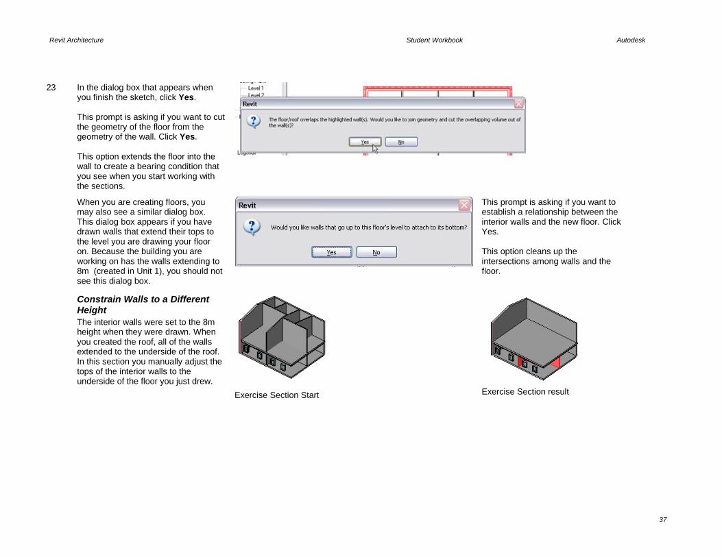
23 In the dialog box that appears when you finish the sketch, click Yes. This prompt is asking if you want to cut the geometry of the floor from the geometry of the wall. Click Yes. This option extends the floor into the wall to create a bearing condition that you see when you start working with the sections.
When you are creating floors, you may also see a similar dialog box. This dialog box appears if you have drawn walls that extend their tops to the level you are drawing your floor on. Because the building you are working on has the walls extending to 8m (created in Unit 1), you should not see this dialog box.
This prompt is asking if you want to establish a relationship between the interior walls and the new floor. Click Yes. This option cleans up the intersections among walls and the floor.
Constrain Walls to a Different Height The interior walls were set to the 8m height when they were drawn. When you created the roof, all of the walls extended to the underside of the roof. In this section you manually adjust the tops of the interior walls to the underside of the floor you just drew.
Exercise Section Start
Exercise Section result

Revit Architecture Student Workbook Autodesk
38
24 Hide the outer walls and roof in the 3D view: • Open the 3D view. • Select the two visible exterior walls
and the roof. • On the View toolbar, click the
Hide/Isolate icon. Hide/Isolate is a view-specific tool that is useful when working in a 3D view displaying a lot of data.
When the tool is active and a component is hidden or isolated, the icon on the View toolbar changes color to indicate that the view contains hidden data.
25 Select all the interior walls: • Right-click an interior wall. Click
Select All Instances.
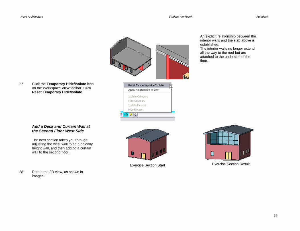
26 On the options bar, click Attach. Click the floor located on Level 2.
Revit Architecture Student Workbook Autodesk
39
An explicit relationship between the interior walls and the slab above is established. The interior walls no longer extend all the way to the roof but are attached to the underside of the floor.
27 Click the Temporary Hide/Isolate icon on the Workspace View toolbar. Click Reset Temporary Hide/Isolate.
Add a Deck and Curtain Wall at the Second Floor West Side The next section takes you through adjusting the west wall to be a balcony height wall, and then adding a curtain wall to the second floor.
Exercise Section Start
Exercise Section Result
28 Rotate the 3D view, as shown in images.

Revit Architecture Student Workbook Autodesk
40
29 Remove the wall’s attachment to the roof: • Select the front wall (containing the
double door). • On the options bar, click Detach. • Click the roof.
You can remove explicit relationships at any time.
30 Move the top of the wall 1500 mm above level 2: • Right-click the western wall. Click
Element Properties. • Change the Top Constraint value
from Explicit to Level 2 and the Top Offset field to 1500.
Add a Curtain Wall While a curtain wall in architectural terms is a specific term that applies to a glazing system, in Revit Architecture the Curtain Wall object is not limited to this strict definition.
You can use Revit Architecture curtain wall objects to define many grid-based construction assemblies, including curtain walls and interior modular partitions.
31 Open Floor Plan Level 2.
32 On the Basics design bar, click Wall. Change the wall type on the options bar to Curtain Wall: Exterior Glazing. Before you start drawing, set the height to Level 3 on the options bar.
Curtain walls are considered as wall families. Most of the Instance parameters are the same as for the basic wall families, but the Type parameters are completely different.

Revit Architecture Student Workbook Autodesk
41
33 Draw a vertical wall, as shown in the
image.
34 Open the 3D view.
35 In the project browser, right-click Families > Walls > Curtain Wall > Exterior Glazing. Click Properties.
There are many different ways to access a family’s Properties dialog box.

Revit Architecture Student Workbook Autodesk
42
36 Change the pattern to the spacing as shown: • Vertical Grid: Spacing: 2000. • Horizontal Grid: Spacing: 1200. Click OK to close the dialog box and see the changes in the model.
The pattern layout properties refer to the curtain gridlines. The available options allow for flexible editing.
Selecting Curtain Walls: When you are selecting the curtain wall, as you hover your cursor over the curtain wall, you see either the individual grids of the curtain wall highlight or the outer frame. You are able to perform different functions depending what you select. In this case you want to select the overall rectangle.
Pointer above grid selects individual gridline.
Pointer over edge selects the curtain wall object.
37 Select the curtain wall. On the options bar, click Attach, and then click the roof.
This curtain wall type contains only the grid divisions. Mullions must be placed after positioning the curtain wall. To add mullions, on the Modeling design bar, click Mullion and click any curtain grid. But do so after completing the next section of the exercise where you add a door into the curtain wall.

Revit Architecture Student Workbook Autodesk
43
Add a Section In this part of the exercise you: • Add a section to the project. • Add a door to the curtain wall.
A section, like a level, also creates a view that represents the section. In many cases in Revit Architecture, it is convenient to add a section or an elevation specifically to help you see and access for selection the objects you are working on.
Project shown with curtain wall door in place.
38 Open the view Floor Plan > Level 1.
39 Place the section mark: • On the design bar, click Section. • On the options bar, verify that the
type selector is set to Section: Building Section.
• Click a point for the section bubble at the top left of the floor plan.
• Click a point for the section tail below the first point.
Click a white area of the drawing window to deselect the section mark just drawn.
40 Open the section by double-clicking the Building Section view that was automatically created in the project browser.
If you have drawn a section looking to the left, find the blue double arrow (the same flip arrow you see on doors) and pick it to reverse the direction of the section.
Section Mark Toggles When you select a section marker, you see blue flip arrows and blue cycle head/tail markers.
Reverse section views by clicking the arrow symbols that appear next to the section head.
Section heads and tails can be turned on or off and toggled among the
Revit Architecture Student Workbook Autodesk
44
available loaded ones by clicking the circular arrow symbols next to the section head and tail.
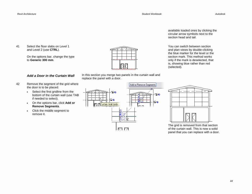
41 Select the floor slabs on Level 1 and Level 2 (use CTRL). On the options bar, change the type to Generic 300 mm.
You can switch between section and plan views by double-clicking the blue marker for the level or the section mark. This method works only if the mark is deselected, that is, showing blue rather than red (selected).
Add a Door in the Curtain Wall In this section you merge two panels in the curtain wall and replace the panel with a door.
42 Remove the segment of the grid where the door is to be placed: • Select the first gridline from the
bottom of the curtain wall (use TAB if needed to select).
• On the options bar, click Add or Remove Segments.
• Click the middle segment to remove it.
The grid is removed from that section of the curtain wall. This is now a solid panel that you can replace with a door.

Revit Architecture Student Workbook Autodesk
45
43 Using TAB, select the new curtain panel that is twice as big as the other ones (position the cursor next to the side of the panel and press TAB until it is highlighted, and then left-click). Open the Properties dialog box by clicking the icon on the options bar.
44 Click Load. Navigate to Metric Library > Doors > M_Curtain Wall Dbl Glass.rfa.
Load family components as needed during the design process.
45 Click OK to accept and close the Properties dialog box. Open the 3D view to see the change.
Copy Components from One Level to the Other
46 On the Window menu, click Close Hidden Windows.
As you work with the different views, they remain open until you close them. Close Hidden Windows enables you to free computer memory by closing

Revit Architecture Student Workbook Autodesk
46
those windows that you are not using.
47 Open the view Floor Plan Level 1.
48 On the Window menu, click Tile.
Alternatively, you can press WT on your keyboard to tile the windows. Tiling windows enables you to work in more than one view at a time. This tool is particularly useful for selecting objects that may not be available from any one view. Any windows that you have minimized at the time do not tile.
Select, Filter, and Copy Components from One Level to the Other In this section you copy some of the windows from level 1 to level 2. In copying the windows, you use several selection tools.
You use the window selection method (picking a point in the screen at left and dragging the pointer right around the objects you want to select). You then use the filter function to remove everything from the selection set but the windows. You then selectively remove some windows from the selection set by selecting while holding SHIFT.
Finally you use Copy and Paste Aligned to copy the windows to level 2.
49 Open Floor Plan 1.

Revit Architecture Student Workbook Autodesk
47
50 In plan view, draw a selection window around the building.
The selection window selects everything within the box created by the two picks.
51 Filter out everything but the windows: • With the building still selected, on
the options bar, click the Filter tool. • Select only the Windows check
box.
52 Remove the western three windows: • Press and hold SHIFT. • Click the three windows on the
west side of the building to remove them from the selection set.
The default selection with the cursor movement is as follows: • Left to right: Include only those
objects entirely within selection box.
• Right to left: Include any element that lies within or is crossed by the bounds of the selection box.
When selecting individual components: • CTRL+click adds to the selection
set. • SHIFT+click removes from
selection set.

Revit Architecture Student Workbook Autodesk
48
53 On the Edit menu, click Copy to Clipboard. On the Edit menu, click Paste Aligned > Select Levels by Name > Level 2.
You can use Paste Aligned on multiple levels at the same time by pressing CTRL and clicking the level names in the dialog box.
Modify a Wall Profile In this last section of the exercise you add a small garden wall around the building and modify the profile of the wall to provide a sculpted top.
54 Open Floor Plan: Site.
55 Add the site walls: • On the Basics design bar, click
Wall. • Wall type = Generic 200. • Height = Unconnected 1500. • Shape = Rectangular.
• Click in the drawing window above
and to the left of the building. • Click in the drawing below and to
the right of the building.
Change wall height as well as any other wall property after it has been positioned by opening the Wall Properties dialog box.
56 Open the 3D view.
Revit Architecture Student Workbook Autodesk
49
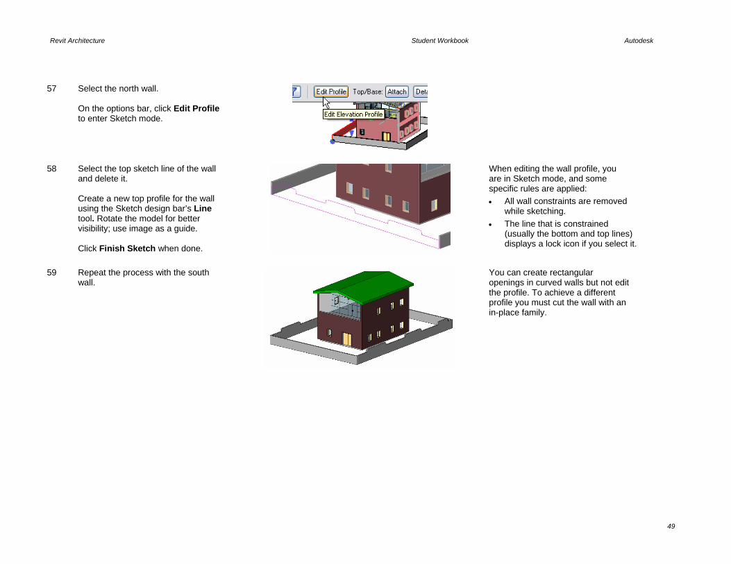
57 Select the north wall. On the options bar, click Edit Profile to enter Sketch mode.
58 Select the top sketch line of the wall and delete it. Create a new top profile for the wall using the Sketch design bar’s Line tool. Rotate the model for better visibility; use image as a guide. Click Finish Sketch when done.
When editing the wall profile, you are in Sketch mode, and some specific rules are applied: • All wall constraints are removed
while sketching. • The line that is constrained
(usually the bottom and top lines) displays a lock icon if you select it.
59 Repeat the process with the south wall.
You can create rectangular openings in curved walls but not edit the profile. To achieve a different profile you must cut the wall with an in-place family.

Unit 3 Theory: Families and Nested Families
Revit Architecture: Editing Types Control for how Revit Architecture components are constructed and located in a project occurs at the family, type, or instance levels. In general the family controls the geometry, the type controls the size, and the instance controls the location in space. In this unit you work with families and types. You create a new wall type and window type by duplicating existing types in the project. There are two kinds of families in Revit Architecture: system families and component families. System Families Walls, floors, ceiling, and roofs all are system families. The definition for system families cannot exist outside the project. You create new types of walls by duplicating existing ones in your project and then changing the definition of the copy. In this unit you create a wall type with a sweep for a base and a reveal (cut-out) at the top. You also split the brick, adding a new component to the wall base. Component Families As opposed to system families, families such as doors, windows, and furniture can exist outside the project as files with an RFA extension. When you use the Load from Library command, you are loading one of these families. While the type definitions (sizes) are part of the family definition, you can copy and create new types within the project file. In this unit you duplicate an existing window type to create a new size window. This exercise focuses on how to create types within the project. Nested families and the Family Editor for creating new family RFA files are explained in Units 10 and 11. Duplicate a Wall Type
1 Open file Unit 3 – Complete. Open the 3D view and orient the view as shown.
Starting point of Unit 3
Unit 3 Complete

Revit Architecture Student Workbook Autodesk
51
2 Right-click one of the exterior walls. Click Elemental Properties.
To access a component Properties dialog box, select the component and do one of the following: • Right-click the component. Click
Element Properties. • On the options bar, click the Properties
icon.
3 Click Edit/New.
4 Click Duplicate. Enter Exterior - Brick on Mtl. Stud with Base as the new name for the wall type. Click OK to return to the Type Properties dialog box.
It is a good idea to always duplicate an existing type instead of editing it directly, which would change the standard Revit Architecture library. You can easily purge excess types later.
5 Click the Edit button next to Structure.
Every wall component has the following properties: layer, function, material, and thickness. Wall components can “wrap” around the wall end or at inserts.

Revit Architecture Student Workbook Autodesk
52
6 If you do not currently see a preview at the left side of the Edit Assembly dialog box, click Preview in the bottom left of the dialog box.
The preview pane displays the components in the views selectable from the drop-down menu below the preview.
Load and Add a Wall Sweep In this section you load and add a wall sweep to the wall.
Both sweeps and reveals (additive and subtractive geometry) are created and stored as profiles. A profile is just a set of closed lines saved as an RFA file.
7 Default view is plan structure. In the View list located on the left pane, select Section.
The layer determines how wall components clean up with each other. The material determines what hatch is shown when the wall is cut in section or plan or viewed in elevation along with the shading and rendering textures. Materials also affect how walls clean up. Note that the lower part of the structure window becomes active only if you switch the preview to Section.
8 In the right pane, click Sweeps.
Sweeps and reveals are profile-based. The Sweep and Reveal dialog boxes allow for direct profile loading.
9 In the Wall Sweeps dialog box, load a new wall style into the project: • Click Load Profile. • Browse to Metric Library >
Profiles. • Click M_Wall Sweep Brick Soldier
Course.rfa. • Click Open.

Revit Architecture Student Workbook Autodesk
53
10 In the Wall Sweeps dialog box, click Add.
11 Use the list to set the profile to the Soldier Course: 1 Brick. Click the Material line. Click the Browse icon. In the material selection page, double-click Masonry Brick Soldier Course.
12 Verify that the other values default to the values shown.
13 Click OK to return to the Edit Assembly dialog box.
The brick sweep you applied appears at the lower-left corner of the wall.
Add a Reveal A reveal is like a sweep, but instead of adding to the wall form, it subtracts from it.
The process and dialog boxes are the same. However, the profile already exists in the project because it was loaded into the original template.

Revit Architecture Student Workbook Autodesk
54
14 You should still be in the Edit Assembly dialog box. Click Reveals.
15 Click Add and set: • Profile = M_Reveal-Brick Coarse: 1
Brick. • Distance = 3200. • Offset = 20.
The profile determines the shape. The distance determines how high to place the reveal on the wall. The offset moves the reveal into or out of the wall.
16 Click OK to close each dialog box and return to the drawing window.
Reveal Sweep
The sweep and reveal are applied to the wall. The sweep adds a soldier course base. The reveal removes a strip from the brick at 3200 mm.
More on Sweeps Walls cannot have vertical sweeps set in the type, but they can be added manually from Modeling design bar > Host Sweep > Wall Reveal/Wall Sweep. You can also use this tool to create a horizontal instance of sweeps or reveals.
Sweeps and reveals clean up correctly at angles and inserts unless the inserted family contains specific solid elements in the family itself (that is, an exterior or interior door frame) that may interfere with the sweep/reveal. It is possible to grip-edit sweep at inserts and corners to redefine them. It is also possible to modify the sweep return around the corner. Select any sweep, and check the available options on the options bar.
A profile is an external family that consists of linear geometry. You define a closed line shape (similar to Sketch mode) and save it as a family. Then you load the profile into the project as you would a door or window. However, unlike a door or window family, profiles cannot be used directly in the project but must be assigned to a sweep type definition (applied sweeps, roof slab edges), or directly to the object (wall and railing type definitions).
Split the Brick Layer You can split the vertical components of a wall, adding different materials.
17 Return to the Edit Assembly dialog box for the wall you have been working with.
Right-click the wall with the reveal and sweep. Click Properties > Edit > New. Click the Structure Edit button.

Revit Architecture Student Workbook Autodesk
55
18 Click Split Region. Hold your cursor over the masonry brick exterior layer on the preview. Click near the bottom of the wall to divide the brick structure into two parts.
19 Click Modify. Click the line dividing the two brick regions.
]
To select this edge, you probably need to use the hover and tab process: Hold your cursor over the split you made in the brick component. Do not select with the left mouse button yet. Use TAB to cycle through the various faces that you can select. Watch the edges highlight each time you press TAB. As you do this, watch the status bar at the lower-left corner of the application window. The status bar displays a description of what will be selected if you click at that time.
20 With the edge selected, use the temporary dimension that appears to move the line to 900 mm above the bottom of the wall. Click the text of the temporary dimension, and type 900.
Add a New Wall Component This section leads you through creating a new component with a different material to assign to the piece you just split.
21 Click Layer 1. Click Insert to create a new layer.

Revit Architecture Student Workbook Autodesk
56
22 Change the new component’s settings: • Function: Finish 2 [5]. • Material: Finishes – Concrete
Cast In Situ. • Thickness: Do not change.
23 Make sure the layer row with the new component is selected. Click Assign Layers.
Once the regions are divided, it is not possible to edit the width of the component, as the system sets the default value to “variable thickness” according to how it is used within the wall type. That is, you could assign the same layer material to two different regions, laying on two different components, each with a different width.
24 Click the lower part of the exterior brick component in the Preview pane to assign the new wall component to it.
25 Click OK to close each dialog box and return to the drawing window.
26 Select the remaining three exterior walls. On the options bar, change their type to the new type Exterior - Brick on Mtl. Stud with Base.
You can split wall components into as many regions as you want, but creating complex walls should be done only when the design idea and the construction method are clear. Otherwise, editing the regions can become difficult when there are many of them.
Revit Architecture Student Workbook Autodesk
57
The wall you just modified belongs to a system family. It cannot exist outside the project (RVT file) as a file you can edit. You create new types by duplicating existing types as in this exercise.
External (Hosted) Families: When you load from library, you are loading a separate file—a family (RFA) file. These files store the basic geometry and parameters for components such as doors and windows.
External families are also termed hosted families. Although this makes sense for doors and windows that are hosted by a wall, other components may be hosted by different components. For example, ceiling light fixtures must be placed on a ceiling. You cannot create an instance of a ceiling light unless there is a ceiling in the project. In general, all components that you load from the library are hosted at least by the level you place them on.
Load a Window Family
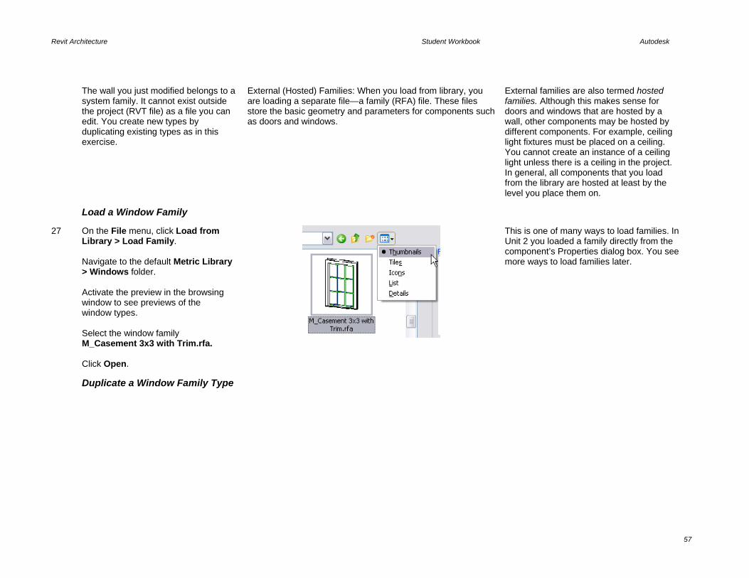
27 On the File menu, click Load from Library > Load Family. Navigate to the default Metric Library > Windows folder. Activate the preview in the browsing window to see previews of the window types. Select the window family M_Casement 3x3 with Trim.rfa. Click Open.
This is one of many ways to load families. In Unit 2 you loaded a family directly from the component’s Properties dialog box. You see more ways to load families later.
Duplicate a Window Family Type

Revit Architecture Student Workbook Autodesk
58
28 Change windows from Fixed to Casements family of the same size: • In the project browser, select
Families > Windows > M_Fixed. Right-click 0915 x 1220 mm. Click Select All Instances.
• On the options bar, change the window type to M_Casement 3x3 with Trim 0915 x 1220 mm.
Selecting families from the project browser is a convenient way to create a selection set for a specific family type. Because it is not view specific, it selects all types contained in the model. You can also select all instances by right-clicking one of the windows in any view and clicking Select All Instances.
29 Without deselecting the windows, right-click. Click Element Properties.
30 Click Edit/New. The Edit/New button opens the Element Properties dialog box. You can define Type parameters and Instance parameters during family creation.
31 Click Duplicate. Type 1100 x 1400 mm for the name. Click OK to return to the Element Properties dialog box.
Duplicating the window type and modifying the window family do not automatically update the family file (RFA) stored outside the project file. You export the family to your library at the end of this exercise. It’s a convention to name types using their size so that other people using families can easily trace and understand them. In a team, conventions are a fundamental part of

Revit Architecture Student Workbook Autodesk
59
optimizing the design process, making it easier to share the data consistently.
32 Change Height value to 1400 and Width value to 1100. Click OK to close each dialog box and return to the drawing window,
There are many parameters in this dialog box that vary in type: length, material, text, and other component-specific properties. Try changing the materials to see what happens.
Export the Window Family
33 On the File menu, click Save to Library > Save Family.
Remember to save in a location that makes sense. In this example it is the Workbook Data folder. It is a good practice to keep your personal libraries separate from the default installed library.

Revit Architecture Student Workbook Autodesk
60
34 In the Family to Save list, select the family M_Casement 3x3 with Trim.
If you save your libraries in the same folder as the Revit Architecture libraries, you might lose all of them if you forget to pull them out before upgrading to the next release of the software. So, make it a habit to create your own library folder.

Revit Architecture Student Workbook Autodesk
61
Unit 4 Theory: Parameters
Revit Architecture: Dimensions, Doors, and Windows In this unit you explore dimensioning of doors and windows. Dimensions for Locating Objects When you work with doors, you work with both temporary and permanent dimensions. Temporary dimensions appear anytime a model object is selected in a view. When the object is deselected, the dimension disappears. Permanent dimensions are an annotation placed in the current view. Permanent dimensions are specific to the view and do not show up in other views. Dimensions are much more than instructions to the contractor to build these elements at this location. Dimensions in Revit Architecture are one of the mechanisms for locating objects accurately in the building model. Dimensions for Modifying Subcomponent Locations Within a Family In the second section of this exercise you work with dimensions within the window family. Many families have parameters that allow control of the relationships and locations of the subcomponent parts. These relationships are often established by family type. Modifying these parameters affects all instances of that type. Also defined by the family are instance parameters. A general rule is that the instance parameters control the location of an object within its host. Each of these parameters is determined by the author of the family. They can differ from family to family, and you quickly become familiar with accessing both the instance parameters and type parameters when working in the Revit Architecture environment. Add Doors and Locate with
Temporary Dimensions
1 Open file m_Unit 4 – Start. Open Floor Plan Level 2. Zoom into the east area of the building.
The highlighted walls have been added for you.

Revit Architecture Student Workbook Autodesk
62
2 On the Basics design bar, click Door. On the options bar, select door type: M_Single-Flush: 0762 x 2134 mm. On the options bar, clear the Tag on Placement check box.
3 Position the cursor over the vertical wall, as shown in the image.
The opening side of the door is defined while you position the door by moving the cursor from one side of the wall to the other.
Pressing SPACEBAR while positioning the door changes the swing direction.
4 Click to place the door. Try to place it so that the opening is in front of the perpendicular wall.
A Warning dialog box displays if there is a conflict between the door and the wall. If you want, you can ignore this warning and resolve the problem later. Click the Close (X) button to dismiss the warning, or just proceed to the next door.

Revit Architecture Student Workbook Autodesk
63
5 On the Basics design bar, click Modify, and select the door. On the Options bar, clear the Tag on Placement check box.
When you select a door, two symbols appear. Use them to invert opening side, swing direction, or both.
Invert swing.
Invert side.
6 Click the text of the dimension that is attached to the horizontal wall in the middle. The value becomes editable. Type 10cm and press ENTER.
7 Add more doors to the other rooms as shown: • Type = M_Single-Flush: 0864 x
2134 mm.
Place doors, as shown in the image. Use temporary dimension to get an idea of location relative to walls.
Relocate Witness Lines You can change where the witness lines of the temporary dimension are located.
You edit temporary dimensions with the control boxes (blue squares) on each witness line. Just click a control box and drag it to a new position, or right-click it and then click Move Witness Line.
Left-clicking a temporary dimension control box toggles the witness line to another point on the object. There is a limited set of points that the witness lines can find with this method.
8 Select the door on the right side. Temporary dimensions appear, but they won’t help you to adjust the position for this door, which must be placed in the adjacent room.

Revit Architecture Student Workbook Autodesk
64
9 Drag the blue square to a new position (face of the far vertical wall) and then release to validate the position, as shown in image. Click the text of this dimension, and the value becomes editable. Type 10cm. Press ENTER.
Click blue square (control box) and drag...to the next wall over…….then change the dimension to 200mm.
10 Select the door on the left side. Use the temporary dimensions to adjust the position so that the door is placed 20cm from the vertical wall on the left to the center of the door. Click horizontal control arrows to flip the door.
11 With the door still selected, click the symbol. The temporary dimension
becomes a permanent dimension.
You can use permanent dimensions to annotate your design. They can be useful to place a relationship between components.

Revit Architecture Student Workbook Autodesk
65
12 On the design bar, click Modify. Click the permanent dimension that you just placed. Click the blue lock icon near the dimension line.
When you click to lock the dimension, you are creating an explicit relationship. If you move the wall, the door retains its position relative to the wall. If you delete a dimension that establishes a relationship, Revit Architecture displays a warning asking what you want to do. You can delete the dimension and keep the relationship or simply delete the dimension and the relationship.
13 On the Basics design bar, click Modify. Select the three doors (use CTRL to multiselect). On the Edit toolbar, click Mirror.
14 On the options bar, check that Pick and Copy are selected. Click the horizontal wall on the right side.
Use the options bar to: • Draw or select an axis for the
mirror.
• Choose if you want to copy the
mirrored objects.
Load a Door Family and Change a Type

Revit Architecture Student Workbook Autodesk
66
15 On the File menu, click Load from Library > Load Family. • Navigate to the Doors folder in
the metric library. • Select M_Double-Glass 2.rfa
and click Open. • Open the 3D view and rotate the
model so that you can see the double door.
The easiest way to rotate the model is by pressing SHIFT and the middle mouse button at the same time.
16 Select the door, and on the options bar, click M_Double-Glass 2.rfa: 1830 x 2134 mm in the type selector.
Change Type and Instance Parameters
17 Add two casement windows to level 2: • Open Floor Plan Level 2. • On the Basics design bar, click
Window. On the options bar, click Load.
• Navigate to the Metric Library\Windows folder, select M_Casement with Trim.rfa, and click Open.
• On the options bar, click M_Casement with Trim: 0610 x 0610 mm. Clear the Tag on Placement check box.
• Add two windows on the vertical wall (east side) using the image as a guide.
You can a load a family in a project in many different ways: • On the File menu, click Load from
Library > Load Family. • Select the corresponding button on
design bar, and on the options bar click Load.
• Drag a family from Microsoft® Windows® Explorer and drop it into Revit Architecture.
The casement window is like the casement 3x3 window but without the muntins. Different geometry, different family.
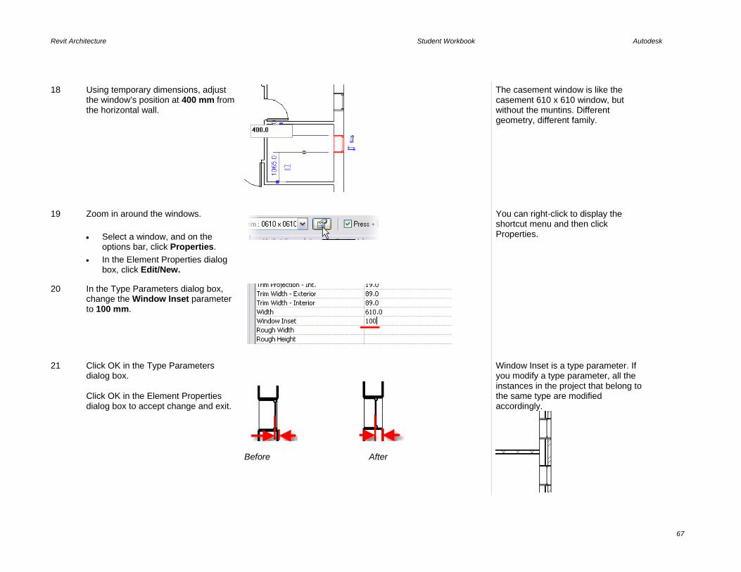
Revit Architecture Student Workbook Autodesk
67
18 Using temporary dimensions, adjust the window’s position at 400 mm from the horizontal wall.
The casement window is like the casement 610 x 610 window, but without the muntins. Different geometry, different family.
19 Zoom in around the windows. • Select a window, and on the
options bar, click Properties. • In the Element Properties dialog
box, click Edit/New.
You can right-click to display the shortcut menu and then click Properties.
20 In the Type Parameters dialog box, change the Window Inset parameter to 100 mm.
21 Click OK in the Type Parameters dialog box. Click OK in the Element Properties dialog box to accept change and exit.
Before After
Window Inset is a type parameter. If you modify a type parameter, all the instances in the project that belong to the same type are modified accordingly.

Revit Architecture Student Workbook Autodesk
68
22 Go to Elevation East and select the window on the right. On the options bar, click Properties.
23 In the Element Properties dialog box, change the Sill Height parameter to 1705 mm.
24 Click OK in the Element Properties dialog box.
When you change an instance parameter, only the selected components are modified.

Revit Architecture Student Workbook Autodesk
69
Unit 5 Theory: Representations
Revit Architecture: Views, Visibility, and Sheets This unit covers the display features and capabilities of Revit Architecture, as well as covering some different presentation methods. This unit includes five exercises: • Exercise 5A leads you through adding a section and detail callout. This exercise also covers adding views to sheets. • Exercise 5B adds some material to the roof of the building. • Exercise 5C illustrates fine-tuning control over the visibility and cleanup of walls in plan view. • Exercise 5D demonstrates how to create a sun and shadow study for your model. • Exercise 5E shows how to import a model created in Revit Architecture to Autodesk® 3ds Max® software for visualization.
Exercise 5A: Sections, Views, and Sheets In this exercise you add a section to the building. You then adjust the view properties for the section and add a detail callout to the section view. At the end of the exercise you create a new sheet and composite the views on the sheet. Add a Section View
1 Open file Unit 5a – Start. • Open Floor Plan Level 1. • Zoom into the two first rooms on the
left side of the building.
2 Right-click in the view. Click View Properties.
You don’t have to open a view to edit the properties. You can simply right-click a view in the project browser and then click Properties.

Revit Architecture Student Workbook Autodesk
70
3 In the Element (view) Properties, dialog box, change the detail level parameter to Coarse. Click OK.
Note that in coarse mode the wall structure is not displayed.
Note: When you set the detail level to medium or fine, the structure is displayed.
Revit Architecture allows three different levels of detail (Fine, Medium, and Coarse). Objects in the project display correctly for each detail level.
The detail level of a view is also available from the Drawing window View toolbar.
4 Open Floor Plans Level 2. • Right-click in the view. Click View
Properties. • In the Element Properties dialog
box, change the Underlay parameter to Level 1.
Revit Architecture enables you to choose which view you want to use as an underlay. The view is dimmed, but you can use these elements for alignments or as a reference for new objects. Any level in the building can be used as an underlay, or simply choose the level below or the level above. You can choose to view the underlay in plan or reflected plan (ceiling) view.
5 Open Floor Plans Level 1. On the Basics design bar, click Section. Select Type Section: Building Section.
6 Draw a line from left to right. Use the image as a guide.
The direction used to draw the section line defines the direction of the section, but it can be flipped later.

Revit Architecture Student Workbook Autodesk
71
Note: Adding a section mark to the drawing adds a new view in the project. This view is automatically added to the project browser under Sections.
7 Click in a white area to end the command and return to the Modify tool. This should deselect the section at the same time.
Double-click in the middle of the circle of the section bubble in the project. (The section bubble should be blue when you do this. In other words, it should not be selected.)
You can also right-click the section line and then click Go to View.
8 Use the window view toolbar to select Shaded with Edges. Press WT on the keyboard to tile the windows. If you have many windows open, either close or minimize any windows you do not want to see. Press WT to tile the windows again.
There are four model graphics style modes: • Shading with Edges • Shading • Hidden Lines • Wireframe
9 Make the view Level 1 current by clicking in the drawing window.
10 Select the section line (click the line, not the round head). Some symbols are displayed next to the section line. Click the arrow symbols to flip the section. Open the section view.
The section view is dynamic. As you flip the section marker, the view changes.
Flip the section. Cycle through different symbols for the section line. Change the symbol at each end of the section line.

Revit Architecture Student Workbook Autodesk
72
11 In Floor Plans – Level 1 view, select the horizontal section line.
Drag the blue double arrow (in the middle of the green dashed line) so that this point is above the exterior south wall.
When you move this point, you change a view parameter value: Far Clip Offset. You can change it in the view properties by assigning a value in the field.
12 Make the section view active.
The section view is now cut by the far clipping plane.
Add a Detail Callout A detail callout like a section mark creates its own view in the project browser.
13 On the design bars View tools, click Callout. • On the options bar, change the Type
to Detail View: Detail. • Check that Scale is set to 1:20.
You can modify the scale later in the callout view properties.
14 Draw a detail frame (click and drag) around the intersection between the floor and the exterior wall on the right side of the building, as shown in the image.
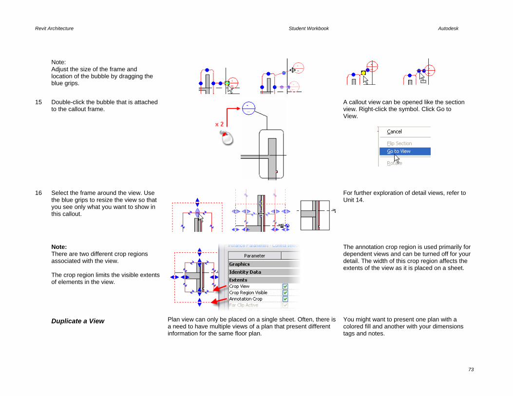
Revit Architecture Student Workbook Autodesk
73
Note: Adjust the size of the frame and location of the bubble by dragging the blue grips.
15 Double-click the bubble that is attached to the callout frame.
A callout view can be opened like the section view. Right-click the symbol. Click Go to View.
16 Select the frame around the view. Use the blue grips to resize the view so that you see only what you want to show in this callout.
For further exploration of detail views, refer to Unit 14.
Note: There are two different crop regions associated with the view. The crop region limits the visible extents of elements in the view.
The annotation crop region is used primarily for dependent views and can be turned off for your detail. The width of this crop region affects the extents of the view as it is placed on a sheet.
Duplicate a View Plan view can only be placed on a single sheet. Often, there is a need to have multiple views of a plan that present different information for the same floor plan.
You might want to present one plan with a colored fill and another with your dimensions tags and notes.

Revit Architecture Student Workbook Autodesk
74
17 In the project browser, right-click Floor Plans - Level 1 > Duplicate View > Duplicate.
Duplicate a view with detailing (Duplicate with Detailing) or without (Duplicate). If you click Duplicate, then none of the detail components (those that are view specific, such as dimensions, tags, annotations) are duplicated.
18 In the project browser, right-click Copy of Level 1. Click Rename.
In the Rename dialog box, enter a new name for the view: Level 1 – Area. Click OK.
19 On the Window menu, click Close Hidden Windows. • In the project browser, open Floor
Plans –Level 1. • On the Window menu, click Tile. You can now see the views side by side.
20 In any view, move a wall. Notice that in all other views, that wall moves accordingly.
Keep in mind that it’s the same wall in the same building. When you move that wall in any view, all other views where that wall is visible automatically update.
Even if you copy a view, you can choose to display it with a different scale, different detail level, different shading mode, and so forth.
Work with Shade and Shadow Revit Architecture provides the ability to work with shade and shadow directly in any view.
This is part of the view properties called advanced model graphics.

Revit Architecture Student Workbook Autodesk
75
21 Set the West Elevation current. On the Drawing Window View toolbar, click the Shadow icon. Click Advanced Model Graphics.
22 In the Advanced Model Graphics dialog box: • Select the Cast Shadows check
box. • Click the Browse (...) button for Sun
and Shadows Settings.
23 Change the preset to Sunlight from Top Left.
The sunlight from top left is in relationship to the plan view of the building.
24 Click OK to close each dialog box and return to the drawing window.
The shadow is now generated on the elevation. If the shadows do not show up immediately, change to a different view and return to this, or press the refresh key (F5).

Revit Architecture Student Workbook Autodesk
76
Create Sheets In Revit Architecture, a sheet is another view of the building model. Sheets are listed in the project browser in their own category directly above the family list.
The overall flow is as follows: • Create a sheet. • Place any of the views (plans, sections,
elevations) on the sheet by dragging it onto the sheet view.
• Adjust the properties of the plan view to meet your presentation needs.
25 In the project browser, right-click Sheet. Click New Sheet.
26 In the Select a Titleblock dialog box, click OK (use the default A1 metric).
To choose another title block, you have to first load them in your project. To load a title block, click the Load button in the Select a Titleblock dialog box and load a title block RFA file as you would any other type of Revit Architecture family.
27 In the project browser, drag Floor Plans – Level 1 onto the sheet.
Revit Architecture won't let you place the same view twice on a sheet or the same view on two separate sheets. Instead, you duplicate the view you want to place on two separate sheets. The crop region determines the size of the view on the sheet. By default, the view is set to the extents of the objects in this view.

Revit Architecture Student Workbook Autodesk
77
28 In the project browser, right-click Floor Plans – Level 1. Click Properties, and change View Scale Parameter to 1:50. Click OK.
The view’s scale determines how large an area it takes up on the sheet.
29 Open Floor Plans Level 1: • Select the elevation marker by
dragging a window selection with the cursor.
• Drag the west elevation marker away from the surrounding low wall.
• Repeat with the other markers but move them toward the wall.
The elevation mark has two pieces: the circle and the triangle. Select them both.
30 Open the sheet: • Notice that the size of the view now
incorporates the new location of the elevation markers.
• Move the view into the middle of the sheet by left-dragging the view.
The title of the view also moves with the plan view.
Note: As you hover your cursor over the view on the sheet, you get two different options, depending on whether your cursor is over the boundary of the view or the title of the view.
Click the viewport to move the view, activate the view, or resize the title mark.
Click the title mark if you want to move the title mark.

Revit Architecture Student Workbook Autodesk
78
31 Move the title mark: • Click the shape handle (the title
mark line). • Left-drag the line into place on the
sheet.
If you cannot get the tooltip to appear with Viewports: Viewport: Viewport 1: Shape Handle, watch the status bar at the lower left for the same information.
32 Adjust the title mark length: • Click the view border to activate the
blue grips. • Grip-stretch the right grip to make
the title line shorter or longer.
Adjust the Crop Region for the View
33 In the project browser, right-click Floor Plans – Level 1. Click Properties. Select the Crop Region and Crop Region Visible check boxes to turn on the crop region for the view. Set view Floor Plans > Level 1 current.
The view now has a visible crop region.

Revit Architecture Student Workbook Autodesk
79
34 Select the crop region, and drag the blue grips toward the building.
35 Open the sheet view. The drawing sheet now reflects the smaller bounds established by the crop region. Select the viewport in the sheet. Click the Properties button. Change the scale of the viewport to 1:100.
The properties of the viewport are linked to the properties of the view, in this case Floor Plan Level 1. When the view scale changes back to 1:100, the size on the sheet changes.
36 Complete the sheet: • Move the Level 1 view on the sheet
in the upper left and resize the title mark.
• Turn on the crop region for level 2, verify that its scale is 1:100, and drag it from the project browser onto the sheet to the right of Level 1.
• In the same way, place elevations (west/north) and the Section 2 onto the sheet, adjusting the crop regions and scale as needed to fit.
Take a look at the symbol of the section line.
Revit Architecture recognizes what sheet this section is positioned on and automatically fills in this information in the section bubble. Place the section on any other sheet, and the bubble updates. Section bubbles are families that can be customized to display

Revit Architecture Student Workbook Autodesk
80
other information.
Exercise 5B: Display Control of Materials This exercise takes you through creating a material for the roof in the project from the last exercise. In creating the roof you create a new Revit Architecture Material. Material definitions control the color of the object in Shade mode, the rendered material, what pattern the object displays when cut by a section, as well as what pattern is displayed when the object is seen in a projection. Create a New Roof Type
This section of the exercise is long. You duplicate the existing roof type to create a new type and then assign different materials to the layer components of the roof.
You also duplicate a material and create a model pattern and drafting pattern for the roof material you create.
1 Open i_Unit 5b – Start. Set Floor Plans: Level 3 view current.
The east side has been returned to a sloped condition for you to better illustrate the behavior of the patterns for the material you define in this exercise.
2 Right-click in the view. Click View Properties. In the view’s Element Properties dialog box, next to View Range, click the Edit button.
3 Set the Top offset to 10000.0. Set the Cut Plane offset to 10000. Click OK to close each dialog box.
Setting the cut plane to a high value helps to ensure that if you raise the slope of the roof, it isn’t cut in this view. You must keep the top of the primary range above the cut plane.
4 Click the roof. On the options bar, click Properties.
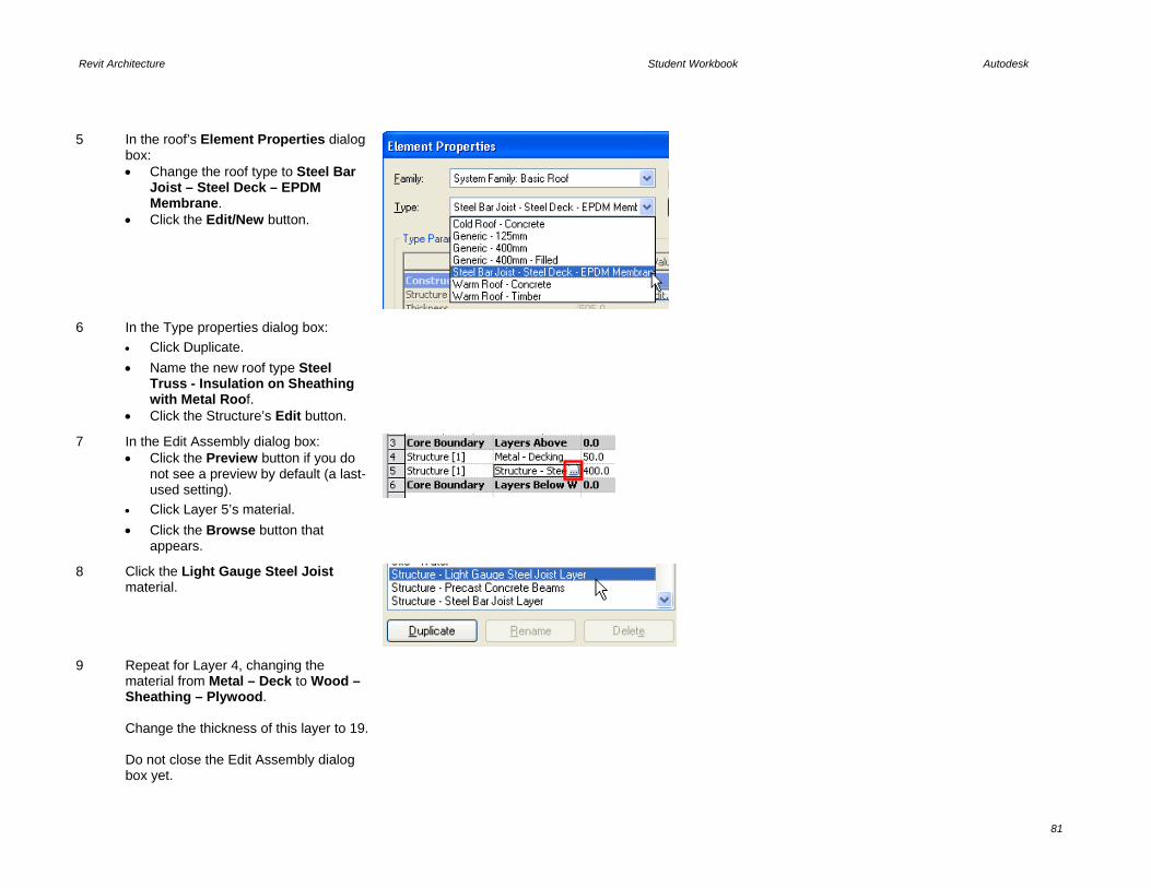
Revit Architecture Student Workbook Autodesk
81
5 In the roof’s Element Properties dialog box: • Change the roof type to Steel Bar
Joist – Steel Deck – EPDM Membrane.
• Click the Edit/New button.
6 In the Type properties dialog box: • Click Duplicate. • Name the new roof type Steel
Truss - Insulation on Sheathing with Metal Roof.
• Click the Structure’s Edit button.
7 In the Edit Assembly dialog box: • Click the Preview button if you do
not see a preview by default (a last-used setting).
• Click Layer 5’s material. • Click the Browse button that
appears.
8 Click the Light Gauge Steel Joist material.
9 Repeat for Layer 4, changing the material from Metal – Deck to Wood – Sheathing – Plywood. Change the thickness of this layer to 19. Do not close the Edit Assembly dialog box yet.

Revit Architecture Student Workbook Autodesk
82
Create a New Material and Assign to the Roof Type In this section you continue editing the assembly but create a new material on the fly.
All materials defined in the project file can be accessed by clicking Materials on the Settings menu. In this example you access these material definitions directly from the Edit Assembly dialog box.
10 Click Layer 1’s material. Click the Browse button that appears.
11 Click the Metal Panel entry. Click Duplicate.
12 Enter Metal – Roofing Standing Seam as the name of the new material.
13 In the Material dialog box, under Shading, click the Color button, and pick a teal green color for the roof.
This color is used only when the view is set to Shading or Shading with Edges.
14 There currently are no standing seam materials provided with the software. If you have a JPG, you can create an AccuRender™ material from the image file. Because you are not going to render this building, for this exercise leave this setting as you found it.
15 The Surface Pattern is empty for this material. There is no Standing Seam fill pattern either. You create these patterns on the fly in the next section.
Create a New Fill Pattern for the Material
In this section you create a new fill pattern on the fly to use in the material you just created.

Revit Architecture Student Workbook Autodesk
83
16 Click the Browse button to the right of the empty Surface Pattern field.
17 In the Fill Patterns dialog box: • Click Drafting. • Click New.
18 In the New Pattern Dialog box: • Set Orientation in Host Layers to
Align with Element. • Click Simple. • Name the pattern Standing Seam
Drafting. • Set the line angle to 90. • Set the line spacing to 7. • Click Parallel Lines.
19 Click OK to close each dialog box and return to the drawing window.
Drafting patterns change their scale depending on the view scale. Changing the scale of the view to 1:20 keeps the plotted distance between the lines consistent at 7 mm.

Revit Architecture Student Workbook Autodesk
84
Create a Model Fill Pattern and Assign to the Material
In this section you modify the material to use a new model fill pattern.
20 On the Settings menu, click Fill Patterns.
21 This time click Model, and then click New.
22 In the Add Surface Pattern dialog box set:
• Type = Simple. • Name = Standing Seam
(Model). • Line Angle = 90. • Line Spacing = 750 mm. • Click Parallel Lines.
Click OK to close each dialog box.
23 On the Settings menu, click Materials.
24 Select Standing Seam (Model) from. the new roof material’s surface pattern list.
Model surface pattern dimensions are set by the fill pattern definition and do not vary by drawing scale.

Revit Architecture Student Workbook Autodesk
85
Exercise 5C: Fine-Tuning Wall Cleanup and Display This exercise illustrates some of the different display and cleanup control you have over walls in your Revit Architecture project. Set Wall Fill for Coarse Level Display
This setting is a type parameter for the wall.
Revit Architecture walls have a separate control for the display detail level Coarse. This coarse fill pattern and color enable you to poche the entire width of the wall regardless of the number of components in the wall. See also the end of this exercise for overriding the fill pattern for all walls.
1 Open file Unit 5c – Start. Open Floor Plan Level 1. Verify that the view’s detail level is set to Coarse.
2 Select any wall. Open its Properties dialog box.
3 Click the Edit/New button to access the wall’s type properties.
4 Verify that the Coarse Scale Fill Color is Black.
5 Click in the Value field of the Coarse Scale Fill Pattern parameter. Click the Browse button that appears in the field.

Revit Architecture Student Workbook Autodesk
86
6 Select Solid Fill for the fill pattern.
7 Click OK to close each dialog box and return to the drawing window.
Because this is a type parameter, you need to repeat this process for all wall types used in the project.
Global Control of Linework Display of the Walls: Object Styles
In addition to the coarse display control, Revit Architecture provides the ability to override the system default display of walls for a specific view.
9 Set the View Detail level to Medium.
10 Click Settings menu > Object Styles.
11 In the Objects Styles dialog box, Model Objects tab, scroll down the list of objects and expand the Walls category.
The Object Styles dialog box controls the lineweight, color, and linetype. This is also the location where you can assign materials to obects. In all cases if the object is set to “By Category” for any of these parameters, these are the values referred to.

Revit Architecture Student Workbook Autodesk
87
12 Change the Walls Cut Line color to blue and the Common Edges to red.
Changes you make in the Object Styles dialog box are global and apply to all views.
13 Click OK to return to the drawing window.
The object styles are now applied to all wall types in the project. The wall’s Cut (pen 3 and blue) refers to the outer edge of the wall. The wall’s subcategory Common refers to the lines common to the layers within the wall.
Override of Linework Display of the Walls: View Visibility/Graphics by Category
Each view has its own override to the global object style settings. A couple of the previous exercises have used this control to manipulate how objects are displayed in specific views.
The Visibility/Graphics dialog box also holds overrides to the wall component display graphics.
14 Open the View properties for Floor Plans: Level 1. Next to Visibility/Graphics Overrides, click the Edit button.
15 In the Visibility Graphics Overrides dialog box: • Scroll down the list to Walls. • Click the wall line. • Click the override button in the
Cut/Lines column. • Set the override weight to 4. • Set the override line color to a dark
green. Click OK to close each dialog box and return to the drawing window.
These changes are for the current view only.

Revit Architecture Student Workbook Autodesk
88
16 Return to the view’s Visibility/Graphics Overrides dialog box: • On the Model Objects tab, set the
Override Model Patterns Cut Pattern Color to dark red.
Click OK to return to the drawing window.
The override applies to all cut patterns for all layers in the wall type.
Override of Linework Display of the Walls: View Visibility/Graphics and Cut Line Styles
17 Return to the view’s Visiblity/Graphics Overrides dialog box: • Under Override Host Layers, select the
Cut Line Styles check box. • Click Edit. • Set Structure[1] to lineweight 5. Click OK to close each dialog box and return to the drawing window.
Any layer in the wall type definition assigned to the structure layer now has the wider (pen 5) lineweight assigned to it.
18 Return to the view’s Visiblity/Graphics Overrides dialog box: • Click the Cut Line Style’s Edit button. • Set Core Layer Clean-Up to Use
Function. Click OK to close each dialog box and return to the drawing window.
This setting affects only the layers within the core of the wall type’s definition.

Revit Architecture Student Workbook Autodesk
89
19 Return to the view’s Visibility/Graphics Overrides dialog box: • Click the Cut Line Style’s Edit button. • Set Core Layer Clean-Up to Use
Common Edge Style. Click OK to close each dialog box and return to the drawing window.
This setting affects only the layers within the core of the wall type’s definition. Joins between individual walls are shown, but using the common edge style graphic line.
20 Repeat the previous step and set Core
Layer Clean-Up to No Edge. No edges are shown at the core cleanup
condition between joins.
Wall Cleanup and Joins Revit Architecture walls automatically clean up as they are
added to the project. This section guides you through control of some special conditions.
21 Zoom into Condition A in the project. On the toolbar, click the Edit Wall Joins tool.
22 Hover your cursor over the intersection of the walls until you see a square appear around the intersection. Click that area.
Once you have selected an intersection to edit, the configuration control appears on the options bar. The Next and Previous buttons cycle through various ways you can clean up this intersection.
23 Click Square Off and then Next until you cycle through to the solution shown at right.

Revit Architecture Student Workbook Autodesk
90
24 While still in the Edit Wall Joins mode, click the intersection of the inverted T at Condition C.
This illustrates a condition that might happen when a new wall abutts an existing wall. In this case you do not want the core penetrating through the existing (horizontal) wall.
25 On the options bar, from the Display list, select Don’t Clean Join.
The join is disallowed, and the wall does not cut through the existing brick face.
26 Click the Modify tool to exit the Edit Wall Joins function. Zoom into the other intersection at Condition C.
This condition is similar to the last; however, there are three walls that make up the intersection. You cannot disallow all joins because you still want the two existing walls to clean up.
27 Click the right wall of the three walls at this intersection. Right-click the blue end grip of this wall. Click Disallow Join.

Revit Architecture Student Workbook Autodesk
91
28 Drag the wall end to the exterior face of the existing brick.
Wrap the End of the Wall You have control over the wrapping behavior of each of the components in a wall type definition.
29 Zoom into Condition B in the project. • Right-click the wall. Click Element
Properties. • Open the Type properties of the horizontal wall by clicking Edit/New.
In this case the brick does not wrap around the end of the wall to provide closure to the curtain wall.
30 Change Wrapping at Ends to Exterior. Click OK to close each dialog box and return to the drawing window.
The exterior layers now wrap around the end of the wall.
31 Return to the type parameters of the wall and click the Structure Edit button. Clear the Wraps column for both Thermal Air Layers. Click OK to return to the drawing window.
Within the structure of the wall type, you can control which layers wrap.
Join Geometry You have control over the wrapping behavior of each of the components in a wall type definition.

Revit Architecture Student Workbook Autodesk
92
32 Right-click the wall at Condition D. Click Create Similar. • Draw a vertical wall from the number 1
to 2.
As long as the walls do not cross near the end of a wall, the walls clean up.
33 Right-click the wall at Condition E. Click Create Similar. Draw a vertical wall from the number 3 to 4.
If crossing walls do not clean up, you can use the join geometry tool to force the cleanup.
34 On the toolbar, click the Join Geometry tool.
35 Click one of the walls, then the other.
The two walls now clean up with each other.
Override All Wall Fill Patterns This exercise opened with the coarse fill pattern type property
for walls. You also have the ability to override the fill pattern for all walls as a view graphics override similar to the linework override earlier in this exercise.

Revit Architecture Student Workbook Autodesk
93
36 Type VG on the keyboard to open the visibility graphics override for this view. On the Model Categories tab, scroll down the list and select Walls line to activate it.
Click in the override field in the Cut: Patterns column.
Keyboard shortcuts are just the two keys typed on the keyboard. There is no need to press ENTER after you type the shortcut. This dialog box is the same as if you had opened the view properties and clicked the Visibility Edit button.
37 Click the Browse button. Click the Solid Fill pattern.
The override is applied to all wall types in this view but does not affect other views.
38 Save and close the project.
Exercise 5D: Sun and Shadow Studies This exercise leads you through using the sun and shadow features of Revit Architecture.

Revit Architecture Student Workbook Autodesk
94
Duplicate the 3D View In this section you create a new 3D view for the sun studies using the Dynamic View tool.
Duplicating a view is not required for creating a shadow study. However, because many of the settings for the sun studies are view specific, creating a view specifically for the sun study enables you to keep these settings for this view and create other views with different sun settings.
For example, you could have three different 3D views, one with the sun settings for December 21, another for March 21, and a third for June 21.
1 Open file m_Unit 5d – Start.
Verify that the 3D Views: {3D} is current. On the toolbar, click the Show Mass tool.
2 Click the Dynamically Modify View tool.
3 In the Dynamic View dialog box: • Click the expansion bar at the right
of the Dynamic View dialog box. • Click Orient to a Direction, and click
Southwest Isometric. • Click the Save icon and name the
new view Southwest Isometric Sun Study.
1 2 3
Set the Sun Study Parameters The view’s advanced model graphics stores the sun and shadow parameters.
You can access the advance model graphics either through the view properties or the shortcut menu of the drawing area window as shown here.
4 In the drawing window, click the Shadows menu. Click Advanced Model Graphics.

Revit Architecture Student Workbook Autodesk
95
5 In the Advanced Model Graphics dialog box: • Select the Cast Shadows check
box. • Click the Sun and Shadows
Settings button.
6 In the Sun and Shadow Settings dialog box: • Click the Single-Day tab. • Click By Date, Time and Place and
set the location to your city or enter the values directly with the Asimuth and Altitude settings.
• If you do not have a toposurface in the model (discussed in Unit 12), verify that the Ground Plane at Level check box is selected.
Click OK to close each dialog box and return to the drawing window.
Preview the Sun Study in the View With the sun study parameters set, you are now ready to view the sun and shadows cast on the building model.
7 On the Shadows shortcut menu of the drawing window, click Preview Solar Study.
8 On the options bar, click the Play button.
The sun study plays through the day, cycling at the interval specified in the sun and shadow settings.
Click the Next Frame button to walk

Revit Architecture Student Workbook Autodesk
96
through the study.
Export the Sun Study to an AVI File
With the sun study parameters set and previewed, you are ready to export the sun study to a movie format file.
9 On the File menu, click Export > Animated Solar Study.
10 In the Save As dialog box, set the following: • Name the AVI file. • Change the frames per second to 1
as you have left the default at 1 frame per hour. Having 15 frames per second would make for a very short AVI file!
• Adjust the format display mode and dimensions to your preferences.
• Click Save.
11 Change the compression codec if you want. Click OK.
The compressors available depend on what software is installed on your machine. Full Frames is the most compatible compression method, but also produces the largest file.

Revit Architecture Student Workbook Autodesk
97
Exercise 5E: Importing a Revit Architecture Model into Autodesk 3ds Max The following exercise describes how to import a Revit Architecture model into Autodesk 3ds Max software for visualization. For more detailed exercises on working with 3ds Max, refer to the Autodesk Visualization Supplemental Curriculum. Set up Your Model for Export 3ds Max cannot import Revit Architecture project (RVT) files
directly. You can, however, export the model to an AutoCAD® drawing file and then load the file into 3ds Max.
This exercise does not have a starting workset but illustrates the general process of linking a Revit Architecture model into 3ds Max. You can work with your own project or any of the workbook projects. The screen captures utilized in this exercise uses the m_Settings.rvt file in the training folder of the Revit Architecture content. If you wish to use this dataset, we have included a copy in the Extra RFA files folder included with the curriculum This exercise file has some materials already assigned such as brick and glass. For this example, we have additionally assigned a beige stucco material to the remaining exterior walls (this texture has already been added if you utilize the dataset in the extra RFA files folder noted above).
This stucco material has a JPG material map. It is assigned to the wall along the left side of the elevation shown in the Revit Architecture model.
1 Before exporting your model, find the appropriate 3D view. Either use the default 3D view, or create your own by placing a camera.

Revit Architecture Student Workbook Autodesk
98
2 If you prefer to set up a camera, simply go to a plan view. On the View design bar, click Camera.
3 Click once to place the camera. Click again to establish the view direction.
4 Use the Dynamic View tools to adjust the view to your liking. With the camera in place, your 3D view is now ready for export to DWG™ format.
Export Your Model Revit Architecture exports data in a variety of file formats, including DWG format.
5 To export your design to the DWG format, click File menu > Export > CAD Formats.

Revit Architecture Student Workbook Autodesk
99
6 Verify that Save as Type is set to AutoCAD DWG 2007 format. Click Current View. Accept the other default values in this dialog box. Click Save. Choose a location to save your exported model.
7 When exporting a camera view, you see an alert indicating the crop region will not be exported. Click OK.
Use a section box on a 3D view to limit the geometry exported to the DWG file.
Link Your Model to 3ds Max
You can either import DWG files into a 3ds Max session or link them. Linking a DWG file to a 3ds Max session gives you the advantage of making subsequent changes in Revit Architecture and reloading them, via an exported DWG file, into 3ds Max without any data loss.
8 To link the exported DWG file: In 3ds Max click File menu > File Link Manager.

Revit Architecture Student Workbook Autodesk
100
9 In the File Link Manager dialog box, Attach tab, click File. Browse to the exported DWG file. Select the exported DWG file. Click Open to return to the File Link Manager.
10 Open the preset to verify that the cameras created in Revit Architecture are also available in 3ds Max: In the File Link Manager dialog box: • Click Presets tab. • Click the Revit preset. • Click Modify.
If you do not want to modify the provided Revit preset, copy it and then modify it.

Revit Architecture Student Workbook Autodesk
101
11 There are several options on this tab. To ensure that your Revit Architecture cameras are available in 3ds Max, make sure the Views check box is selected. Save your modifications and then go back to the Attach tab in the File Link Manager dialog box. Click Attach This File to load the DWG file into 3ds Max. Then click Close.
12 If you receive a proxy message, click Yes to proceed with link. Your model is now loaded into 3ds Max. Close the File Link Manager.
13 You can change the view to one of the camera views created in Revit Architecture by simply right-clicking the view name in the upper-left corner of the viewport and then clicking Views > Camera: View # (where # represents the number of the Revit Architecture camera).

Revit Architecture Student Workbook Autodesk
102
14 From this shortcut menu, you can select the same camera to modify its location in the other views.
15 Finally, the materials that are applied in Revit Architecture are accessible in the 3ds Max environment: • On the Rendering menu, click
Material/Map Browser. The materials in the scene are the AccuRender materials read from the original Revit Architecture model. They have maintained the same names.
16 When listed in the Material Editor, the materials carry with them bitmaps assigned to them with the Revit Architecture model. When rendered, the assigned material maps come through without any manipulation in the 3ds Max Material Editor.

Revit Architecture Student Workbook Autodesk
103
Once again, for in-depth coverage of 3ds Max, refer to Autodesk Visualization Supplemental Curriculum.

Revit Architecture Student Workbook Autodesk
104
Unit 6 Theory: Design Constraints
Revit Architecture: Levels, Reference Planes, and Grids This unit covers the basics of design constraints. You create gridlines, and then use the array tool to look at the constraint tools it offers. You then add walls, constraining them to the gridlines. In the second part of this unit, you create a roof by extrusion that is constrained to reference planes. Add a New Level Each time you create a level, Revit Architecture automatically
creates a view for that level. If you don’t want a view for a level, clear the Make Plan View check box on the options bar.
In this case you are going to make the plan view so that you have a view you can work in to modify the foundation later.
1 On the File menu, click New > Project. Click the Browse button. Navigate to the folder that contains Workbook Metric Template.rte provided with the data set. In the project browser, open Elevations South.
Double-click the black triangle on an elevation symbol in the project to automatically open the corresponding elevation.
2 On the Basics design bar, click Level and click two points below Level 1. It does not matter where you click (use the image as a guide).
To place a new level you must be in elevation view or in a section view.
3 With the level still selected, click the text of the temporary dimension of this new level. Change the value to 600.
If you know the absolute elevation of a level, you can type it directly by clicking the text that is below the level line while still in the command.

Revit Architecture Student Workbook Autodesk
105
4 On the Basics design bar, click Modify Select the level you’ve just added. Drag the blue dot on the left until it is aligned with the existing ones. Do the same for the blue dot on the right.
Revit Architecture helps you here: As soon as the points are aligned, Revit Architecture displays a green dashed line along these points. You then see a blue lock icon, which indicates that all the points are locked together. If you move one, all the others follow.
5 Click the squiggle grip to offset the mark from Level 1.
6 Drag the blue circle grips to adjust the leader away from the mark.
7 Click the name of the new Level (Level 3). Change this name to T.O.F. (Top of Foundations). Revit Architecture asks if you want to rename the corresponding view. Click Yes.
You can choose to rename the level in the project browser by right-clicking this view and clicking Rename.
Add Gridlines Gridlines and level line marks behave much the same way and have similar controls.
8 In the project browser, open Floor Plans Level 1. On the Basics design bar, click Grid.
The direction used to draw the gridline defines the side where the bubble is attached.

Revit Architecture Student Workbook Autodesk
106
9 Click two points to place the first vertical gridline. Pick from bottom to top, or south to north.
If you draw it in the wrong direction, you can use the check box that appears at the end of the gridline when the gridline is selected.
Note: The same concept applies to level markers.
10 On the Basics design bar, click Modify and select the gridline in the project. On the Edit toolbar, click Array. On the options bar, set the following: • Select Linear. • Select Group and Associate. • In the Number box, type 5. • Select Move to 2nd. Click the gridline, move your cursor to the right, and on the keyboard type 6m and press ENTER.
When you‘ve finished the array, you can easily change the number of copies. If necessary, click an element in the array to display the number of copies.
Adjust Arrayed Elements Modifying a dimension between arrayed elements modifies all arrayed elements.

Revit Architecture Student Workbook Autodesk
107
11 Click gridline 2. On the options bar, click Activate Dimensions.
12 Click the dimension that appears. Type 5700 for the distance
The entire grid system adjust to the new dimension.
13 Select all the vertical gridlines. On the options bar, click Ungroup.
Each gridline can now be moved individually. Now that you've ungrouped the element, the number of elements in the array can no longer be changed automatically. The gridlines adjust as if you had used the Copy tool to create the five gridlines.
Add Horizontal Grids
14 On the Basics design bar, click Grid. Click two points to place the first horizontal gridline from right to left. Press ESC twice.
15 Zoom around the bubble of the horizontal gridline. Select the gridline. Click the text in the bubble, change the value to A, and press ENTER.

Revit Architecture Student Workbook Autodesk
108
16 Create an array with this gridline. Clear the Group and Associate check box. The distance between two lines should be 4m and the number of copies set to 4.
Arrays in Revit Architecture are powerful. You can move one element in the array and all the others move accordingly. Note, however, that this occurs only if you have selected Group and Associate from the options bar before array creation.
Add Foundation Walls Constrained to Grids
When you draw foundation walls, by default they extend down from the current level rather than up from it. You can change the view range to see these walls as they are drawn.
17 Right-click in the view. Click View Properties. In the Element Properties dialog box, next to View Range, click Edit.
The foundation wall is positioned below the current level. If you don’t change view depth, you cannot see the new wall that you are going to add.
18 From the View Depth list, select Level Below (T.O.F). In the View Range dialog box, click OK. In the View Properties dialog box, click OK.
19 On the Basics design bar, click Wall. On the options bar: • Select Basic Wall: Foundation - 300 mm
Concrete. • Set Depth to Level T.O.F. • Check that alignment is set to Wall
Centerline. • Clear Chain. Draw a first wall from the intersection between lines 1-A and intersection 1-C. Click the lock icon to lock the wall with the
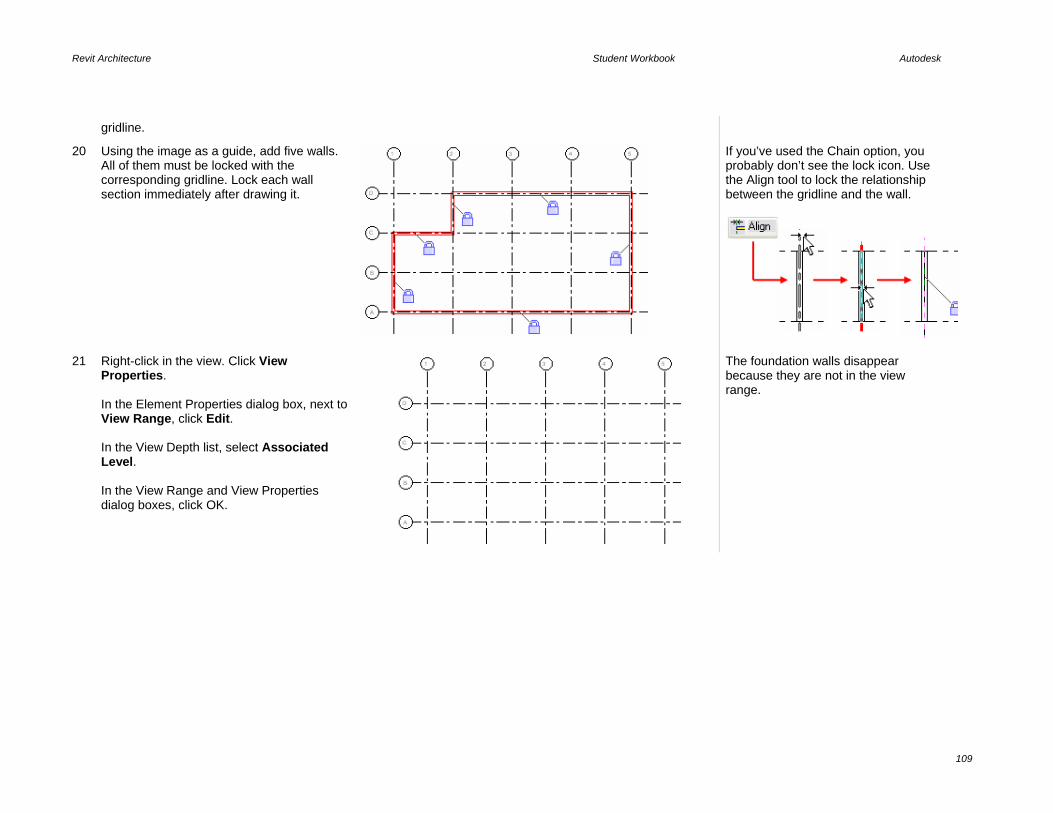
Revit Architecture Student Workbook Autodesk
109
gridline.
20 Using the image as a guide, add five walls. All of them must be locked with the corresponding gridline. Lock each wall section immediately after drawing it.
If you’ve used the Chain option, you probably don’t see the lock icon. Use the Align tool to lock the relationship between the gridline and the wall.
21 Right-click in the view. Click View Properties. In the Element Properties dialog box, next to View Range, click Edit. In the View Depth list, select Associated Level. In the View Range and View Properties dialog boxes, click OK.
The foundation walls disappear because they are not in the view range.

Revit Architecture Student Workbook Autodesk
110
22 On the Basics design bar, click Wall. On the options bar: • Set type: Basic Wall: Generic- 200 mm. • Set Height to Level 2. • Check that alignment is set to Wall
Centerline. • Clear the Chain check box. Using the image as a guide, add these walls. All of them must be locked with the corresponding gridline. Lock each wall section immediately after drawing it.
Add Structural Members Like foundation walls, structural members are often drawn down from the current level to the level below. This setting is similar to Walls on the options bar.
If you do not see the Structural tab on the design bar, you can add it by right-clicking anywhere on the design bar and clicking it on the shortcut menu.
23 Go to Floor Plans Level 2.
You can see the walls below because Level 1 is set as an underlay for the view by default in the workbook template you started with.
24 On the Structural design bar, click Structural Column. On the options bar, set: • Type = UC-Universal Column:
305x305x97UC. • Depth = Level 1. Click the intersection between gridline B and 2.
Structural components are automatically locked with gridlines. Click exactly at the intersection. Zoom in if necessary. Most of the structural elements, including the foundation, are drawn extending down. This includes the foundation wall and the structural columns.

Revit Architecture Student Workbook Autodesk
111
25 On the options bar, click Grid Intersection and do one of the following: • Hold CTRL as you select gridlines B, C,
3, 4. OR • Select the intersection of these grids
with a selection window from right to left across the grids as shown at far right.
26 On the options bar, click Finish. Press ESC twice to end the command.
The columns have now been added to the project.
27 Select all the columns in the project. Open their element properties and verify: • Base Level = Level 1. • Top Level = Level 2. • Top Offset = 0. Click OK.
Flex the Building With some walls and columns in the project and locked to the gridlines, you can now adjust the dimensions between the gridlines and all the constrained components update accordingly.

Revit Architecture Student Workbook Autodesk
112
28 Set current Floor Plans – Level 1. Move gridline 2 4M left. Click the Modify tool. • Click gridline 2. • Click the Move tool. Click anywhere in the drawing window. Move your cursor to the left. Type 4M and press ENTER.
Because the wall between grids C and D along grid 2 has been locked or constrained to grid 2, it, the foundation wall below this view, and the column along this grid all move with the gridline.
Add an Extruded Roof—Create and Set Work Plane Unit 1 led you through creating a simple roof by footprint. When you create a roof by footprint with the Pick Walls option, there is a soft or inherent constraint between the roof and the walls that generated it.
In this part of the exercise, you create a roof by extrusion. The extrusion roof is a shape generated by lines drawn in a reference plane perpendicular to the normal plan working plane. Once constructed, the extruded roof’s start and end points are defined by the location of its reference plane.
29 Go to Floor Plans Level 1. On the Basics design bar, click Reference Plane. Add a reference plane on the west and east sides of the building. Press ESC twice.
Drawing a reference is like drawing a line; you simply click two points (start, end).

Revit Architecture Student Workbook Autodesk
113
30 Select the reference plane on the west side. Change the value of the temporary dimension to 1000. Convert the temporary dimension to a permanent one.
To convert a temporary dimension to a permanent dimension, simply click the symbol below the dimension line.
31 Click the dimension line to select it instead of the column line. Click the lock icon that appears. Perform the same operations for the east side.
32 Select the west side reference plane. On the options bar, click Properties. In the Element Properties dialog box, type Roof Shape in the Name parameter. Click OK to return to the drawing window.
Add Roof by Extrusion In this section, you use the reference plane as a work plane to draw an extruded roof.
33 Open the 3D view. On the Tools toolbar click Work Plane Visibility.
The blue grid is the work plane on which you are working when you create the sketch. In most cases Revit Architecture automatically creates a work plane that enables you to sketch. If Revit Architecture can’t find a solution, it prompts you to select a suitable work plane.

Revit Architecture Student Workbook Autodesk
114
34 On the Basics design bar, click Roof > Roof by Extrusion.
35 In the Work Plane dialog box, select Roof Shape from the Name list. Click OK.
As you can see, if you name a reference plane, it automatically creates a work plane. This is a useful feature. Work planes can be defined by a face on an object (a wall, for example), a reference plane, or a line. Notice that each of the gridlines is automatically considered to be a work plane.
36 In the Roof Reference Level and Offset dialog box, click OK to accept Level 2 as a reference level for the roof.
37 Open the 3D view. On the Tools toolbar, click Work Plane Visibility.
The work plane is aligned with the reference plane placed previously. To sketch the roof, it would be easier to have a point of view perpendicular to the work plane.
Note on setting views to work planes: For this exercise you change to the west view in the next step to draw your sketch line. However, if you do not have quick access to an elevation or a section that looks at the work plane, you can use the dynamic view to set the 3D view to the work plane.

Revit Architecture Student Workbook Autodesk
115
The view orients to the work plane and shows as much of the model as possible. In this case it is backward, so you use the west elevation instead.
38 Set the West Elevation current.
39 With the Lines tool selected on the design bar, click Arc Passing Through Three Points on the options bar. Draw an arc using the image as a guide. On the design bar, click Finish Sketch.
40 Set the 3D view current. On the View menu, click Orient > Northwest. Highlight an exterior wall, press TAB, and click to select the walls.
Shade your view if you want.

Revit Architecture Student Workbook Autodesk
116
On the options bar, click Attach and select the roof.
41 Go to Floor Plans Level 2. On the Tools toolbar, click Align. Click the east reference plane. Click the edge of the roof.
The roof is cut by the cut plane of the view.
Introduction to View Templates A view template stores all the parameters of a view. You can create and apply these as needed to quickly adjust the view settings.
42 In the project browser, right-click Floor Plans: Level 2. Click Duplicate.
43 You should now be working in a view titled Copy of Level 2. On the View menu, click Apply View Template. Select Structural Framing Plan from the list. Click Apply. Review the changes in the drawing window, but do not close the dialog box. Select Site Plan. Click Apply. Review the changes in the drawing window, but do not close the dialog box. Finally, select Architectural Plan. Click Apply. Click OK.
The cut plane for a framing plan is much lower, so you see less of the roof. Also, the columns that were gray now appear solid.
For the site plan, the scale changes as well as the view range, which shows the entire roof.

Revit Architecture Student Workbook Autodesk
117
Create a View Template
44 Right-click in the view. Click View Properties. In the View Properties dialog box: • Change the name to Roof Plan. • Next to View Range, click the Edit
button.
45 In the View Range dialog box, change the Top and Cut Plane values to 12m. Click OK two times to return to the drawing window.
46 On the View menu, click Create View Template from View. Type Roof Plan View Template for the template name. Click OK two times to return to the drawing window.

Revit Architecture Student Workbook Autodesk
118
47 Change to the Level 2 view. In the project browser, right-click Floor Plan Level 2. Click Apply View Template. Select Roof Plan View Template from the list. Click OK.
The view template you made and its parameters are applied to the Level 2 view as well. The next unit explores view templates in more depth.
Add a Strip Footing
48 Open the 3D view. Click the Work Plane Visibility tool to turn off the grid.
49 On the Structural design bar, click Foundation > Wall.
The Continuous Footing tool adds a spread footing at the base of a wall. In this case, you add the continuous footing at the bottom of the lower of the two walls.
50 Click the lower wall to add the continuous footing to the lower stem walls.
Now that your model is filled out, explore the constraints still on the walls and gridlines. Create more reference planes in a section view that are nonorthogonal to the project. Name the reference planes and set a 3D view to orient to them. With these skew reference planes as the work plane, what objects can you draw? What objects are you prohibited from drawing?

Revit Architecture Student Workbook Autodesk
119
Unit 7 Theory: Design Information Organization
Revit Architecture: Components, Groups, Categories, and Subcategories This unit has four exercises. • 7A provides a quick overview of the organization and structure of Revit Architecture design objects. • 7B explores the user-created organizational system of Revit Architecture groups. • 7C continues the exploration of groups and the ability to convert a group to a linked file or vice versa. • 7D leads you through breaking a view into two dependent views to place a larger plan onto two sheets.
Exercise 7A: View Templates, Categories, and Subcategories In this exercise you create and apply a view template to explore the categories and subcategories of object styles that are the basis for object organization and structure in Revit Architecture. Create a New View and Apply a
View Template
1 Open file m_Unit 7a – Start. The file should open with the Floor Plan Level 2 active. In the project browser, right-click Floor Plans: Level 2. Click Duplicate View > Duplicate with Detailing.
The plan view has a view template assigned to it (Architectural Plan 1-50). Duplicate with Detailing copies the annotation elements that are placed in that view. The new view has dimensions, tags, and other annotation copied from the original view. Although you could use Duplicate rather than Duplicate with Detailing here, you are going to take care of these elements with a view template.

Revit Architecture Student Workbook Autodesk
120
2 Right-click Floor Plans: Copy of Level 2. Click Rename. Rename this to Level 2 Furniture. Tile the Level 2 and Level 2 Furniture views.
3 In the project browser, hold CTRL and select both the Level 2 and Level 2 Furniture views. Right-click. Click Apply View Template. Click the Furniture Plan 1:50 template. Click OK.
Both views have now been updated with the new set of visibility parameters stored in the view template.
4 In the project browser, right-click the Level 2 view. Click Apply View Template. Click the Architectural Plan 1-50. Click OK.
The Level 2 view is returned to its original state.
Edit the Furniture Plan View Template
In this section you edit the view template parameters to turn off the furniture and door tags.

Revit Architecture Student Workbook Autodesk
121
5 On the Settings menu, click View Templates. Set the view template to edit to Funiture Plan 1-50. Next to Visibility/Graphics Overrides, click Edit.
6 On the Model Categories tab, note that Plumbing Fixtures has no overrides in place.
When there are no overrides in place, a view uses the By Category setting. In such cases the objects look to the Settings > Object Styles for display parameters. There are no overrides set for this view template.
7 Expand the Furniture category.
These are the subcategories of Furniture. In general, subcategories are established by the families as you load them into the project. You create a new subcategory later in the exercise.

Revit Architecture Student Workbook Autodesk
122
8 Click the Annotation Categories tab. • Clear Door Tags. • Clear Furniture Tags. • Verify that Dimensions, Elevations,
and Sections are cleared. Click OK to close each dialog box and return to the drawing window.
Clearing these elements tells Revit Architecture not to display them when you apply this view template.
9 In the project browser, right-click Level 2 Furniture. Click Apply View Template. Select Furniture Plan 1-50. The door tags and furniture tags have been turned off for this view only.
You can save visibility settings in view templates and recall them to be assigned at any point to any view. The visibility settings define what categories and subcategories are visible within a view. To save the active visibility setting that you define as a view template, on the View menu, click Save as View Template. To apply a view template, on the View menu, click Apply View Template, or right-click in the project browser and then click Apply View Template.
Change an Object Style Globally The object styles control the linework representation for all objects. Changes you make in this dialog box affect all views that do not have an override in place.
Use category/subcategory structure to manipluate the settings for the lineweight, line pattern, and material for the objects.
10 On the Settings menu, click Object Styles.
The Object Styles dialog box has three tabs: Model Objects, Annotation Objects, and Imported Objects. You can control the appearance of model and annotation objects from the first two. On the third tab you can control display settings for imported objects such as DWG format files (line color, weight, style).

Revit Architecture Student Workbook Autodesk
123
11 Scroll down the window to Plumbing Fixtures. Change color to Red. Click OK.
Because styles are not view specific, changing the color of a category affects the display of that category in all views.
12 Open the Level 1 plan view. Verify that the plumbing fixtures have assumed the new color settings. Close the Level 1 plan view.
Create and Assign a Subcategory Subcategories are primarily used by families as a means of providing visibility, lineweight, and material assignment control of the subcomponent of the family.
The following steps are usually done within the family file as illustrated in Unit 11. However, the same theory applies if you create in-place families as has been done on the closet shelves in this project.
13 On the Settings menu, click Object Styles. Expand the Furniture category.
14 Add a subcategory by clicking New. Name the new subcategory Bedroom Closet as a subcategory of Furniture. Click OK to return to the Object Styles dialog box.
15 Change the subcategory color to orange by clicking the color column.
Assign the Closet Shelf to the New Subcategory

Revit Architecture Student Workbook Autodesk
124
16 Select the furniture item inside the closet in the main bedroom (see image). It’s an in-place family. On the options bar, click Edit.
17 Right-click the shelves of the closet (see image). Click Element Properties.
18 Change the subcategory to Bedroom Closet.
19 Select, with the CTRL key, the symbolic lines defining the closet, right-click, and click Element Properties. Assign the subcategory Bedroom Closet.

Revit Architecture Student Workbook Autodesk
125
20 Click OK to close the window. On the design bar, click Finish Family. Note the color change of the components.
The visibility of the Bedroom Closet subcategory can be switched off even if the rest of the furniture is visible. Open the visibility settings for this view and expand the Furniture category. The Bedroom Closet subcategory is now available as a parameter that you can control by object style for all views, or by visibility graphics for view overrides. You can override the color of the category or subcategory by opening the visibility settings for the view and setting a view override.
Override by Element Revit Architecture also provides the ability to override the display of individual elements.
21 Right-click the dresser and bed in the master bedroom. Click Override Graphics in View > By Element.

Revit Architecture Student Workbook Autodesk
126
22 Click the Project Lines expansion arrow. Click the Color button. Change the color to green.
You have quite a bit of control over how individual objects are displayed. This function enables you to override most of the individual element’s visibility properties, including the lineweight, color, and pattern. This function also enables you to override an element’s material surface pattern as well.
23 Click OK to return to the drawing window.
View Filters Revit Architecture provides the ability to control items by category, subcategory, and instance. Within a specific view you also have the ability to create filters that give you further control over the display of objects.
24 Open Level 2 Furniture view properties. Click the Visibility/Graphic Edit button to access the overrides for this view. Click the Filters tab. On the lower portion of the Filters tab, click the Edit/New button.
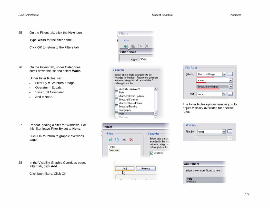
Revit Architecture Student Workbook Autodesk
127
25 On the Filters tab, click the New icon. Type Walls for the filter name. Click OK to return to the Filters tab.
26 On the Filters tab, under Categories, scroll down the list and select Walls. Under Filter Rules, set: • Filter By = Structural Usage. • Operator = Equals. • Structural Combined. • And = None.
The Filter Rules options enable you to adjust visibility overrides for specific rules.
27 Repeat, adding a filter for Windows. For this filter leave Filter By set to None. Click OK to return to graphic overrides page.
28 In the Visibility Graphic Overrides page, Filter tab, click Add. Click both filters. Click OK.

Revit Architecture Student Workbook Autodesk
128
29 Select the Halftone check box for each filter. Click OK to return to the drawing window.
Both of the exterior wall types have the designation Structural Combined and are gray along with all the windows. The interior walls are nonbearing and are not affected by the filter override.

Revit Architecture Student Workbook Autodesk
129
Exercise 7B: Group Basics A group is a collection of Revit Architecture objects that behave as one element. Annotation elements and model elements cannot belong in the same group. When you create a group from a collection of objects that contains both model and annotation elements, you create two groups, a model group and an annotation detail group. This exercise explores the basic functionality of groups along with the relationship between the model and annotation groups. Create a Group
1 Open the data set m_Unit 7b – Start.rvt. Verify that the Floor Plans Level 1 is current. Zoom into the desk and chair (middle left).
2 Select the shelf, door, door tag, windows, window tags, desk, chair, room, room tag, and the right wall of the office: • Click outside the upper-left corner.
Holding the left mouse button, drag the pointer to the outside of the lower-right corner and release.
• Hold SHIFT, and click the left wall to deselect it.
3 On the toolbar, click Group.

Revit Architecture Student Workbook Autodesk
130
4 In the Create Model Group and Attached Detail Group dialog box, set: • Model Group Name = Typical
Office. • Attached Detail Group Name =
Typical Office Tags. Click OK to return to the drawing window.
5 Note that the group has three grips. The middle grip is the insertion point of the group. Drag the insertion grip to the lower-left corner of the space.
Also note that the tags have been moved to a separate group.
Array Typical Office Model Group
6 With the model group still selected, click the Array tool. On the options bar, set: • Array Type = Linear. • Clear Group and Associate. • Number = 9. • Move to 2nd. • Select Constrain.
7 Click anywhere in the drawing window. Drag to the right. Type 3200.

Revit Architecture Student Workbook Autodesk
131
Press ENTER.
8 Click OK in the warning message that appears.
This message tells you that the right wall that is in the group is lying on top of the left wall of the conference room. This is not an uncommon condition when working with groups. One end or both will be unique conditions. Furthermore the warning says that you can hover your cursor over that wall and remove the offending wall from this instance of the group.
9 Hover the cursor over the wall between the conference room and the far right office. Press TAB. Click the wall that highlights. A blue group icon appears with a leader to the wall. Click the blue icon to exclude this wall from this group.
Hover TAB Click
You can also right-click the wall or blue icon and then click Exclude on the shortcut menu.
Edit the Group To change a group’s definition you enter Edit mode.
10 Click any of the model groups. On the options bar, click Edit Group.
The group is open for editing. Those objects not in the group are dimmed and not accessible.

Revit Architecture Student Workbook Autodesk
132
11 Move the desk and chair toward the window. Move the door against the right wall. Rotate the shelf. On the design bar, click Finish.
The change is propagated throughout each of the offices.
Add Objects to the Group
12 Click one of the model groups. On the options bar, click the Edit button. On the Basics design bar, click Component. Add a Chair-Corbu to the office. Click Finish.
Duplicate the Group Once a group has been defined in the project, it acts much like any other Revit Architecture object. You can create types based on the original.
13 Click the fourth model group in the row. On the options bar, click Properties.

Revit Architecture Student Workbook Autodesk
133
14 Click Edit/New. Click Duplicate. Type Large Office for the name. Click OK to close each dialog box and return to the drawing window.
This group now has a different type definition from the other groups. You can also duplicate groups from the project browser.
Modify the New Large Office Group
15 Delete the fifth model groups as shown in the image.
16 Select the Large Office Group. On the options bar, click Edit Group.
17 Change the layout as shown here: • Move the wall 1600 mm east. • Move the door. • Add a credenza to the north wall. • Move the shelf to the west wall,
and change to larger type. • Rotate the desk and chair. • Change the windows to 0915 x
1830 mm and add a third window, moving as needed to center in space.
On the Group toolbar, click Finish.

Revit Architecture Student Workbook Autodesk
134
Apply Group Type to a Different Group
18 Move the fifth model group 1600 mm to the left.
19 With this group still selected, use the options bar Type list to change the type of this group to Large Office.
Groups can be powerful tools for working with sets of objects in the Revit Architecture environment.
Add Annotation Detail Groups
20 Press CTRL and click model groups 2, 3, 6, 7, and 8. On the options bar, click Place Detail. Under Attached Detail Groups, select the Floor Plan: Typical Office Tags check box. Click OK.

Revit Architecture Student Workbook Autodesk
135
Note: Each group now has an associated annotation group. The annotation groups are “pinned” to the model group, forcing them to move together.
There is only one annotation detail group defined in the project so far and that group is not appropriate for the Large Office group.
Duplicate Annotation Detail Group for the Large Office
The detail group for the typical office does not work for the large offices because there is a third window now for the Large Office group.
21 In the project browser, expand the Groups category (at the bottom of the list).
The Groups category in the project browser lists all the group definitions in the project.
22 Right-click the Large Office’s associated annotation detail group Floor Plan: Typical Office Tags group. Click Duplicate.
23 Right-click the new definition Typical Office Tags 2. Click Rename. Enter Large Office Tags as the name.
Both of these groups can be applied to the large office model group.

Revit Architecture Student Workbook Autodesk
136
24 Click the large office on the left. On the options bar, click Place Detail. Under Attached Detail Groups, click Floor Plan: Large Office Tags. Click OK.
The definition is the same but with a different name. You still need to edit the group and add a new tag for the window.
25 With the large office tags attached detail group selected, on the Options Bar, click Edit Group. Right-click one of the window tags. Click Create Similar. On the options bar, clear the Leader check box.
26 Click the untagged window. On the Attached Group toolbar, click Finish.
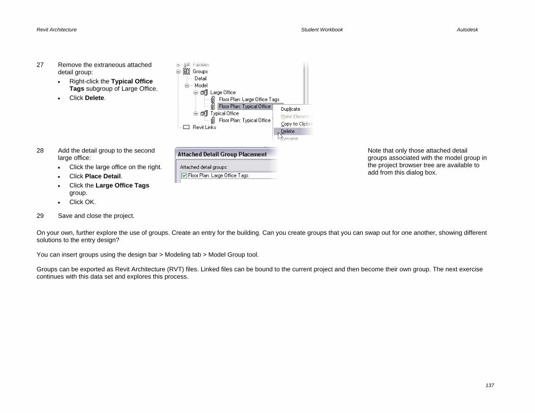
Revit Architecture Student Workbook Autodesk
137
27 Remove the extraneous attached detail group: • Right-click the Typical Office
Tags subgroup of Large Office. • Click Delete.
28 Add the detail group to the second large office: • Click the large office on the right. • Click Place Detail. • Click the Large Office Tags
group. • Click OK.
Note that only those attached detail groups associated with the model group in the project browser tree are available to add from this dialog box.
29 Save and close the project. On your own, further explore the use of groups. Create an entry for the building. Can you create groups that you can swap out for one another, showing different solutions to the entry design? You can insert groups using the design bar > Modeling tab > Model Group tool. Groups can be exported as Revit Architecture (RVT) files. Linked files can be bound to the current project and then become their own group. The next exercise continues with this data set and explores this process.

Revit Architecture Student Workbook Autodesk
138
Exercise 7C: Groups and Links This exercise explores the interaction of groups and linked Revit Architecture files. In this exercise you start with the end point of the last exercise. You make a group out of the string of offices on the south side of the building along with the south wall. Once the larger group has been created, you convert it to a linked Revit Architecture file and copy and paste it to the second floor. Once the file has been converted to a linked file, you have to close the execise project to open the newly created/linked Revit Architecture file for editing. After changing some windows in this file, you close this file and open the original exercise file and explore the changes.
Exercise Start Exercise Complete Create a Floor Group
1 Open file m_Unit 7c – Start. The file should open with the Floor Plan Level 1 active.
This is the result of the last exercise. The attached detail groups have been ungrouped in preparation for making the larger group named South Offices that you export to an RVT file.
2 Drag a selection window from left to right around the interior office groups along with the southern wall and the conference room wall. (Refer to the images to the right and on the next line.)

Revit Architecture Student Workbook Autodesk
139
Note that the south wall has been split to help with this exercise. The images show the left and right conditions as to what should be selected (do not select the small portions at each end of the southern wall).
3 On the toolbar, click Group.
4 Name the model group South Offices and the attached detail group South Office Tags.
5 With the group selected, on the options bar, click Link. In the Convert Group to Link dialog box, click Create New.
6 In the Save Group dialog box: • Browse to where you are keeping
your workbook files. • Leave the file name Same as
Group Name. • Verify that Include Attached
Detail Groups as Views is selected.
• Click Save.

Revit Architecture Student Workbook Autodesk
140
7 Copy the group to the second level: • Select South Offices model group. • On the Edit menu, click Copy to
Clipboard. • On the Edit menu, click Paste
Aligned > Select Levels by Name.
• Click Level 2. • Click OK.
The south wall and all the offices are now copied to the second floor.
Edit the Linked South Offices project file
Revit Architecture does not allow you to have both the main and linked files open at the same time. You must close your exercise file to open the South Offices Revit file.
8 Save and close your project.
9 Open file South Offices from the location where you just saved it. Open the Level 1 floor plan. Click one of the Typical offices. On the options bar, click Edit Group.
10 Change the two windows to 0915 x 1830 mm and move them closer together.

Revit Architecture Student Workbook Autodesk
141
On the Model Group toolbar, click Finish.
11 Save and close the South Offices Revit file.
12 Open file i_Unit 7c – Start. Open the 3D view.
Both instances (first and second floors) are updated with the new definition.
Bind a Linked File Revit Architecture enables you to work the reverse of the process you just completed. You could design the offices in a different Revit Architecture file and then link them into the building shell and bind them.
In practice, some cases call for converting a group to a linked file and others call for linking in a separate Revit Architecture project and binding it to use as a group. As an exploration, this exercise is a bit cyclical and studies both of these tasks. The remainder of the exercise leads you through binding the linked Revit Architecture file. The action of binding a linked file converts it to groups.
13 Select both instances of the linked Revit Architecture file. On the options bar, click Bind. Verify that Attached Details is selected. Click OK.

Revit Architecture Student Workbook Autodesk
142
14 Click Yes to replace the existing group definitions in this project with those defined in the linked file.
The original definitions still exist in this file and are overridden by the definitions in the South Office file.
15 Click Remove Link in the warning dialog box.
The link is removed.
The file now has been updated with the changes, and the southern wall and the offices are now back to being a single group South Offices.
The roof above the entry is completed in Unit 8.
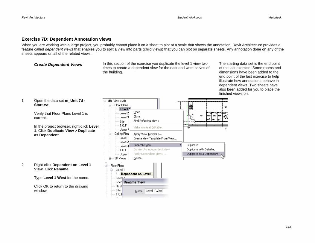
Revit Architecture Student Workbook Autodesk
143
Exercise 7D: Dependent Annotation views When you are working with a large project, you probably cannot place it on a sheet to plot at a scale that shows the annotation. Revit Architecture provides a feature called dependent views that enables you to split a view into parts (child views) that you can plot on separate sheets. Any annotation done on any of the sheets appears on all of the related views. Create Dependent Views In this section of the exercise you duplicate the level 1 view two
times to create a dependent view for the east and west halves of the building.
The starting data set is the end point of the last exercise. Some rooms and dimensions have been added to the end point of the last exercise to help illustrate how annotations behave in dependent views. Two sheets have also been added for you to place the finished views on.
1 Open the data set m_Unit 7d - Start.rvt. Verify that Floor Plans Level 1 is current. In the project browser, right-click Level 1. Click Duplicate View > Duplicate as Dependent.
2 Right-click Dependent on Level 1 View. Click Rename. Type Level 1 West for the name. Click OK to return to the drawing window.

Revit Architecture Student Workbook Autodesk
144
3 Repeat the same process, adding a dependent Level 1 East.
Add Annotation In general, when you add annotation such as tags and dimensions, they are not visible in other views. This is not true for dependent views. Annotation added to any of the views is available in the other views.
4 Level 1 East should be the current view from the last step. Use the Basics design bar Room tool to add a room with tag to the conference room on the far east side.
5 Set the view Level 1 West current.
The tag is visible in this view also as well as the parent view Level 1.
Set the Crop and Annotation Crop Regions
6 In the Level 1 West view, click the crop region to display its grips.
The crop region is the solid line. As you move this, it hides the model object. The red dashed line is the annotation crop region, which gives you control over where you choose to stop the visibility of the annotation such as dimensions and tags.

Revit Architecture Student Workbook Autodesk
145
7 Drag the east side Crop Region control grip just east of gridline 4 (just east of the two larger offices).
8 Drag the annotation crop region to the right past the grid bubble end.
As you manipulate the annotation crop, room tags appear only if the crop region cuts the room and the tag location falls within the annotation crop region boundaries.
9 Drag the crop region controls for the north, west, and east sides, moving the crop region boundaries closer to the building.

Revit Architecture Student Workbook Autodesk
146
10 Set the Level 1 East view current. Repeat the preceding steps to limit this view to the right two bays of the building.
As you do this, notice that if the crop region cuts a dimension string, only full dimensions appear in the view.
Add Views to the Sheets
11 Open Sheet A101- Level 1 West. Left-drag from the project browser the dependent view Level 1 West onto this sheet.
See Unit 5 for more detailed information on adding views to sheets.
12 Repeat, adding dependent view Level 1 East to sheet A102 Level 1 East.
Create a Match Line

Revit Architecture Student Workbook Autodesk
147
13 Set Level 1 Floor Plan current. On the View design bar, click Matchline. Click the Lines tool. Draw a line next to gridline 4. On the design bar, click Finish Sketch.
14 On the View design bar click View Reference. On the options bar, set target view to Floor Plan: Level 1 West. Click the west side of the match line you just created. Repeat, adding another view reference targeted to Floor Plan: Level 1 East to the right of the match line.
The view references are dynamic and change their reference if the views are relocated to different sheets.
15 Save and close the project.

Revit Architecture Student Workbook Autodesk
148
Unit 8 Theory: Domain-Specific Knowledge
Revit Architecture: Roofs This exercise takes you through adding some more detail to the roof in addition to taking a look at how to put together multiple roofs to achieve different forms. Clip the Extruded Roof Any extruded roof (as opposed to a roof by footprint) can be cut
using the Cut Plan Profile tool.
1 Open the data set m_Unit 8 - Start.rvt. Set the 3D view current.
This data set is the same as the building at the end of exercise 7C. The roof is an extruded roof similar to the roof created in Unit 6. Because an extruded roof just passes its form from one plane to another, the extrusion needs to be cut away from the interior of the entry tower.
2 Set the Upper Roof Plan view current. Click the roof in the plan. On the options bar, click Cut Plan Profile.
This process initiates Sketch mode. Just draw the shape you want to remove from the extruded roof. This shape must be closed.
3 Using the Lines tool, draw sketch lines in a shape that follows the outer edge of the upper walls and passes outside the edge of the roof on the west and south sides.
Notice that the linework on the south and west sides is outside the roof. Try not to make the lines coincident with the edge of the roof.
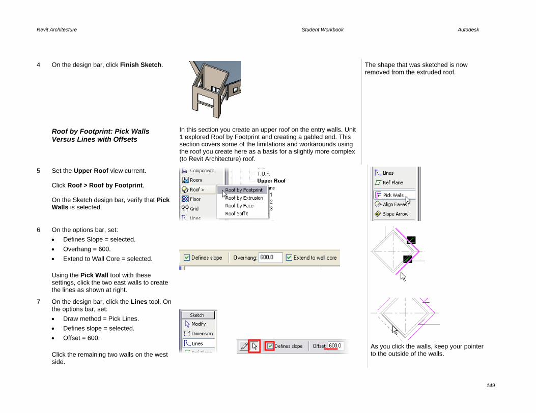
Revit Architecture Student Workbook Autodesk
149
4 On the design bar, click Finish Sketch. The shape that was sketched is now removed from the extruded roof.
Roof by Footprint: Pick Walls Versus Lines with Offsets
In this section you create an upper roof on the entry walls. Unit 1 explored Roof by Footprint and creating a gabled end. This section covers some of the limitations and workarounds using the roof you create here as a basis for a slightly more complex (to Revit Architecture) roof.
5 Set the Upper Roof view current. Click Roof > Roof by Footprint. On the Sketch design bar, verify that Pick Walls is selected.
6 On the options bar, set: • Defines Slope = selected. • Overhang = 600. • Extend to Wall Core = selected. Using the Pick Wall tool with these settings, click the two east walls to create the lines as shown at right.
7 On the design bar, click the Lines tool. On the options bar, set: • Draw method = Pick Lines. • Defines slope = selected. • Offset = 600. Click the remaining two walls on the west side.
As you click the walls, keep your pointer to the outside of the walls.

Revit Architecture Student Workbook Autodesk
150
8 Use the Trim tool to clean up the corners of the sketch lines.
9 On the Sketch design bar, click Roof Properties. • Set Type to Generic 125 mm. • Set the Slope Angle to 25°. Click OK to return to the drawing window.
10 On the Sketch design bar, click Finish Roof.
The roof is created, but it is not symmetrical to the entry walls. This is because of the differences in the lines created by picking walls versus using the Lines tool.
11 Add a section as shown here.
12 Open the section view and tile the two views: Section 1 and Upper Roof.
The sketch lines drawn with the Lines tool originate at the edge of the roof at the level the roof is constrained to (left side of image). The sketch lines drawn with the Pick Walls tool establish the fascia edge of the roof below the level by a distance determined by the slope of the roof over the overhang setting.

Revit Architecture Student Workbook Autodesk
151
13 Toggle the section view to Medium Detail.
Notice also that the Pick Walls tool had Extend to Core selected. The outside face of the core (the metal studs) of the wall is used, and the overhang of 600 is calculated from this point rather than from the exterior face of the entire wall. As such, the overhang on the picked walls is slightly less than the overhang of the drawn line segments.
Align Eaves
Align Eaves is a tool in the Sketch mode of a footprint-type roof.
14 Set the Upper Roof view current. Click the roof. On the options bar, click Edit.
15 Click each of the lines, and use the temporary dimensions to adjust the distance to the face of the wall to 600.
16 On the Sketch design bar, click Align Eaves.
17 Click the eave to align TO (the southeast line). Click the eave to align to that location (the southwest line).

Revit Architecture Student Workbook Autodesk
152
18 Repeat for the northern lines. All the sketch lines should now be set to the same value. On the Sketch design bar, click Finish Roof.
The roof should now be symmetrical to the underlying entry walls.
Create Multiple Roofs
Sometimes you need to create two or more roofs to complete the shape you are looking for. Any roof with a discontinuity in the form probably needs to be created from two different roof objects. This section guides you through creating a simple example of such a roof, as shown at the right.
19 Open the roof sketch for editing. Set the Upper Roof view current. Click the roof. On the options bar, click Edit. Delete the southwest sketch line.
20 On the Sketch design bar, click Lines. On the options bar set: • Draw Method = Draw. • Defines Slope = Cleared. • Offset = 0. Draw the three lines on the west side shown in the image. Verify that these lines do not define slope.

Revit Architecture Student Workbook Autodesk
153
21 On the Sketch design bar, click Finish Roof.
22 Extend the wall to the roof: • Open a 3D view. • Click the southwest wall. • On the options bar, click Top/Base
Attach. • Click the roof to attach to.
Add the Second Roof to Complete the Form
23 Set the Upper Roof view current. Click Roof > Roof by Footprint. Use the Lines tool to draw the lines shown at right. Within the properties of the roof, verify that the type is set to Generic 125 mm and the slope is set to 25°.
Note that only the outermost line (in red) defines a slope. The other three do not.
24 On the Sketch design bar, click Finish Roof.
The roof is finished, but like the first roof in the exercise the linework is based at the upper roof level rather than the eave of the existing roof.
25 Open the section view. Use the Move tool and snaps to move the roof into place, using the roof beyond as the reference.

Revit Architecture Student Workbook Autodesk
154
Add Fascias and Gutters
Revit Architecture provides the ability to sweep a shape around the edge of a roof. This can be any shape stored in a roof sweep type of profile family. One thing to keep in mind about many of the sweeps is that although the shape definition is stored in a family (RFA) file, the definition is buried (or nested) in a system family definition in the project file.
26 Open the 3D view of the project.
27 On the design bar, click the Modeling tab. Click Host Sweep > Roof Fascia.
Note the fascia is a system family (defined only in the project, not as an RFA file). There are other families you can load and use in the project but you would need to duplicate this type and assign the loaded profile into the type parameters of the new type.
28 There is only one type defined in this project.
29 Click the upper edge of the fascia area of a roof. Continue clicking the remaining three edges to add the fascia to each edge of the roof.
30 On the design bar, click the Modeling tab. Click Host Sweep > Roof Gutter.

Revit Architecture Student Workbook Autodesk
155
31 Click the fascia edge about the entry door.
Be careful as you select. Because the inside face of the fascia, the roof, and the outside face of the fascia are all very close together, it is easy to add the gutter to the wrong edge.
Add Soffits Creating a soffit in Revit Architecture is much like creating a roof.
32 Set the Upper Roof level current.
33 Click Roof > Roof Soffit.
34 Using the Lines tool, draw two sets of lines as shown in the illustration.
Although there are automatic selection tools that allow you to select roofs and walls, because this is not just a single roof, you may find it easier to draw the lines manually.

Revit Architecture Student Workbook Autodesk
156
35 On the Sketch design bar, click the Roof Soffit Properties and set the Height Offset from Level to -400.0. Click Edit/New. In the Type Properties box, click Duplicate. Rename the type Generic – 125 mm. Click OK to return to the Type Parameters dialog box.
36 Click the structure lines Edit button. On Layer 2 change the thickness from 300.0 to 125.0. Click OK to return to the drawing window.
37 On the Sketch design bar, click Finish Sketch. Set the Section 1 view current.
38 Click the Join Geometry tool. Click the soffit, and then click the roof.

Revit Architecture Student Workbook Autodesk
157
The two geometries are joined, and the profile line wraps both objects.
Unit 9 Theory: Delaying Specificity
Revit Architecture: Massing There are two exercises in this unit. This first exercise guides you through the process of adding mass elements to a Revit Architecture project. The second illustrates the software’s ability to import SketchUp files and how to use them as mass elements.
Exercise 9A: Mass Components and Building Maker In this exercise you work with Revit Architecture software’s Building Maker. Building Maker is a collection of tools that includes: • Mass elements composed of solid forms and void forms. • Walls, floors, roofs, and curtain systems associated with the mass faces. • • The general workflow in this exercise is to create the mass forms, apply the building elements to the faces, modify the forms, and then update the building
elements to the new geometry of the changed form. Create a Mass Element
1 Open file m_Unit 9a – Start.rvt. Verify that the view Floor Plans–Site is current
The starting point of this exercise is a project that has some 2D linework in place that you can use as guidelines for creating the massing.
At the end of the exercise you have a model with four building massings, one of which has wall, floors, and a roof associated with it.
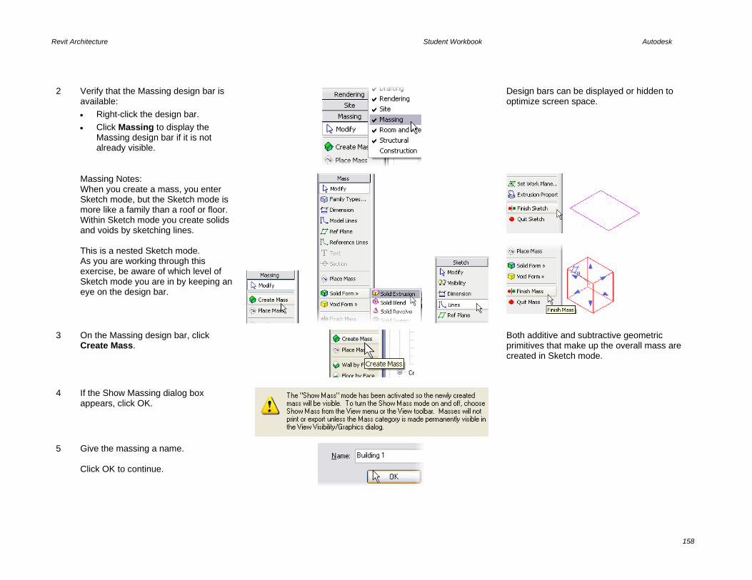
Revit Architecture Student Workbook Autodesk
158
2 Verify that the Massing design bar is available: • Right-click the design bar. • Click Massing to display the
Massing design bar if it is not already visible.
Design bars can be displayed or hidden to optimize screen space.
Massing Notes: When you create a mass, you enter Sketch mode, but the Sketch mode is more like a family than a roof or floor. Within Sketch mode you create solids and voids by sketching lines. This is a nested Sketch mode. As you are working through this exercise, be aware of which level of Sketch mode you are in by keeping an eye on the design bar.
3 On the Massing design bar, click Create Mass.
Both additive and subtractive geometric primitives that make up the overall mass are created in Sketch mode.
4 If the Show Massing dialog box appears, click OK.
5 Give the massing a name. Click OK to continue.

Revit Architecture Student Workbook Autodesk
159
6 On the Massing design bar, click Solid Form > Solid Extrusion.
The geometric shapes that make up the final Revit Architecture mass instance can be created in four ways (Extrusion, Blend, Revolve, Sweep) and can be either solid or void. Voids are subtractive forms that cut geometry from solid forms.
7 On the design bar, verify that the Lines tool is selected On the options bar: • Enter 25 m. • Click the pick lines (the Arrow
symbol).
Sketch lines can be drawn or selected. When selecting, you can automatically lock the lines to the original drawing by selecting the Lock check box on the options bar.
8 Zoom into the upper-right building footprint. Hover the cursor over one of the lines. Press TAB, and then click to select all the lines.
Like selecting a chain of walls, you can click connected lines to generate sketch lines by using TAB.
9 Click Finish Sketch to complete the mass.
Quit Sketch discards the lines that were drawn in Sketch mode. Finish Sketch finalizes the solid, but does not complete the mass because a single mass can comprise multiple solids and voids.
10 Repeat steps 6–9 to create a mass for the small rectangle to the lower right of the solid you just created.

Revit Architecture Student Workbook Autodesk
160
11 Click Finish Mass to complete the mass.
This is the nested series of Sketch modes that creates a mass object. One mode takes you to the mass creation set of design bar options. When you start a solid or void, you drop down one more level and the design bar changes to a more familiar Sketch mode. You must click Finish Sketch and Finish Mass to complete the command.
12 Change to the 3D view. You have drawn two shapes in the mass element Sketch mode. These will be two parts on a singular mass element when selected.
Add the Remaining Masses Return to the site view and repeat the process with all the building footprints in the blocks. The general process is the same as for the mass you just created.
The key points for each building have been noted in the next few steps.
13 Create Building 2 (northwest corner). This building has a simple open area in the middle. As you create the mass, create two chains of sketch lines, one for the outer wall and another for the inner courtyard.
This is a single extrusion with a height of 25 meters.
14 Building 3 at southwest corner: Make this also as a single extrusion. You develop this building later in the exercise, using the void shape to carve out part of the mass.
Extrusion Height = 28 meters.

Revit Architecture Student Workbook Autodesk
161
15 Building 4 Southeast: This mass is two levels. To create the two levels with solid elements you have to create two different solid elements. These can intersect each other.
One mass, two extrusions: Solid extrusion 1 is 36 meters and consists of three separate rectangles for the towers. Solid extrusion two is 12 meters, cuts around the towers, and has two interior rectangles.
16 Open the 3D view. Type SD for a shaded view of the massing. Type HL for hidden line view.
The default material of a mass object is 5 percent transparent. Hidden line shows the beyond conditions because the material is translucent.
17 Resize the northwest mass by dragging the blue grips that appear (one grip for each face).
Edit masses directly in any view by dragging the grips.
Edit the Southwest Mass to Add a Void
The process of adding a void—or subtractive solid—is the same as that for creating the original solid.
18 Click the southwest massing (Building 3). On the options bar, click Edit. Click Void Form > Void Extrusion.

Revit Architecture Student Workbook Autodesk
162
19 On the Sketch design bar, click Set Work Plane. In the Work Plane dialog box, click Pick a Plane. Click OK.
Setting a work plane allows automatic change of the coordinate system in a simple way. You can select any face, reference plane, or gridline as an active work plane.
20 Click the vertical face of the mass located on the lower-left block.
In this case, you are selecting a vertical face directly in the 3D view. Revit Architecture automatically changes the relative coordinate system to vertical.
21 On the design bar, click the Work Plane Visibility button to see the active work plane.
22 Click the Lines tool. On the options bar, set: • Depth = 15000. • Draw tool. • Rectangle shape. Draw a rectangle on the face of the mass as shown at far right. Click Finish Sketch but do not finish the mass.
In this case, the depth refers to the horizontal plane, as you are drawing on a vertical plane.

Revit Architecture Student Workbook Autodesk
163
Voids: The void now cuts 15 meters out of the building. Voids not visible by default show up as you move the pointer over them and make their control grips available once selected.
23 Drag the shape handle of the void until it snaps to parallel geometry to make the void cut completely through the solid. Click Finish Mass to complete the mass.
You do not need to be exact with the void. Once you are done with mass Sketch mode, the void disappears.
Add Floor Faces to the Mass Floor faces help you visualize flooring in the mass element and are used to place floor objects later in the process.
24 Select the southwest massing (the one you have been working with). On the options bar, click Floor Area Faces.

Revit Architecture Student Workbook Autodesk
164
25 Select the check boxes for all the levels. Click OK to return to the drawing window.
Each level that intersects the massing is a candidate for a floor area face. These faces enable you to place floors and do quantity takeoffs from the massing object. Planes are drawn at each level. Already at this phase you can get feedback from the building information model such as the total floor area of the floor faces in the design.
Create a Gross Floor Area Schedule
Revit Architecture provides the ability to get information from the rough mass model, enabling you to dynamically see changes in either the graphical form of the mass or in the tabular form of a schedule.
For the schedule to work, the floor areas must first be assigned to the mass object.
26 On the View design bar, click the Schedule/Quantities tool. Select the Mass category. Click OK to continue to the Schedule Properties.
27 Add fields: • Family and Type. • Gross Floor Area. • Gross Volume. • Description. Click OK.

Revit Architecture Student Workbook Autodesk
165
28 Add a description to Building 3—Office Building. Click OK at the type change prompt.
A gross building volume and floor area schedule can be generated and placed in a sheet. Only the building for which you created the floor faces shows a value in the Gross Floor column of the schedule.
Add the Physical Floor Component
The floor areas created previously are simple vertical divisions of the mass that have no thickness. Use the Floor by Face tool to add floors into the mass.
You cannot use the Floor by Face tool until you have created the floor faces.
29 Isolate the southwest building: • Open the 3D view. • While pressing CTRL, click each of
the three building masses without floor assignments.
• Right-click. Click Hide in View > Elements.
Use Hide Object/Isolate Object to work on one object in the project.
30 Use the View menu to orient the view to the southwest. Click the mass and use the grips to change the height of the lower wing to just under one of the floor area faces.
Add Floors to the Building Now that you have created the mass of the building, you can start adding the building elements.

Revit Architecture Student Workbook Autodesk
166
31 On the Massing design bar, click Floor by Face.
This tool places floor objects at the locations of the floor faces.
32 On the options bar: • Set floor type to Insitu Concrete
225 mm. • Verify that Select Multiple is
selected.
33 Drag a selection window around the whole building. On the options bar, click Create Floors.
The floors are automatically generated.
Create Walls The Wall by Face tool enables you to create walls that are associated with the massing faces in the same way the floors are associated with the floor faces.
34 On the Massing design bar, click Wall by Face.
35 On the options bar, set: • Wall Type = Exterior Brick on Mtl.
Stud. • Draw Type = Pick Face (House
Icon). • Height = Automatic. • Loc Line = Core Face Exterior.

Revit Architecture Student Workbook Autodesk
167
36 Click the faces shown at right.
Spin the model to select these faces. Hold down the scroll wheel and move the cursor to spin the model.
37 Click the Show Mass tool. Click the Show Mass tool to show the mass again.
This tool enables you to move back and forth between seeing the massing and the floors and walls or just the floors and walls. When you open a project that has mass objects in it, you may have to toggle the Show Mass tool on to make the masses visible.
Adjust the Building Envelope (Massing)
With some walls and floor in place, you now modify the mass using grips. As the mass changes, you need to update the floors and walls to the new massing envelope using the Remake tool.
38 Click the Modify tool. Select the mass. Use the triangular face grips to modify the lower wing: • Top face down one level (just
under floor). • South face half the distance to the
street. See illustrations at right.
If stray portions of the mass show up as you grip the mass faces, use the Edit button to access Sketch mode and adjust the void extrusion to clean up.

Revit Architecture Student Workbook Autodesk
168
39 Click any white area to deselect the building.
The building elements are now out of sync with the mass model.
Resynchronize the Building Elements to the New Mass Form
40 Select the floor exposed by dropping the top face. On the options bar, click Remake.
41 Repeat, selecting the lower wing south wall and then clicking Remake.
42 Repeat to remake the lower floors.
Add Curtain Wall System The Curtain System by Face tool enables you to create curtain walls that are associated with the massing.

Revit Architecture Student Workbook Autodesk
169
43 On the Massing design bar, click Curtain System by Face.
44 Verify that the curtain system is set to 1500 x 3000 mm.
45 Click the remaining mass faces that are not occupied by the brick wall type.
46 On the options bar, click Create System.
Adjust Curtain Wall System Spacing
A curtain system is a system family definition that controls the horizontal and vertical spacing of the divisions of the system.
This definition can also hold values for the mullion system, but is not used here.
47 In the project browser, expand Families > Curtain Systems > Curtain System. Right-click the 1500 x 3000 mm type. Click Properties.

Revit Architecture Student Workbook Autodesk
170
48 In the Type Parameters, set the Layout (Grid 1) (vertical spacing of the horizontal grid) to Fixed Distance, and 4000 for the spacing. Also here, set the Layout (Grid 2) to Fixed Distance and 1200. Click Rename. Type 1200 x 4000 for the name. Click OK to return to the drawing window.
Because you are editing the type, the changes you make apply to all curtain systems in the project.
Add Mullions to the Curtain System
49 On the Modeling design bar, click Mullion. On the options bar, click All Empty Segments.
50 Click a curtain system face of the model.
51 Repeat for the remaining curtain system faces.
Add Roof The process of adding a roof is the same as that for adding walls or floors.
52 On the Massing design bar, click Roof by Face. On the options bar, set: • Roof Type = Steel Bar Joist – Steel
Deck – EPDM Membrane.

Revit Architecture Student Workbook Autodesk
171
• Level = 9.
53 Select the top face of the mass. On the options bar, click Create Roof. Repeat, adding a roof at level 3 for the lower wing.
54 On the drawing View toolbar, click the Reveal Hidden Elements tool.
55 Select all three hidden mass instances. On the options bar, click Unhide Element.
56 Click the Reveal Hidden Elements tool to exit Reveal mode.
Note that if you come back to this project later, you may have to click the Show Mass tool to see the mass elements. Show Mass is not turned on by default in a new session.
Exercise 9B: Importing SketchUp Files In this exercise you import a SketchUp file directly into the project as well as import a SketchUp file into a mass family as it is created. Importing the enables you to place walls, floors, and roof as explained in the previous exercise.

Revit Architecture Student Workbook Autodesk
172
Import a SketchUp File The SketchUp models used in this exercise are provided in the same folder as the other exercise data sets.
This exercise starts with the endpoint of the last exercise, but two of the masses have been deleted to make room for the SketchUp models you will use in the exercise.
The exercise ends with two different SketchUp models used in the Revit Architecture project.
1 Open file: m_Unit 9b – Start.rvt. Set the view 3D Views: North East Iso current. Click Show Mass.
2 On the File menu, click Import Link > CAD Formats.
3 In the Import/Link dialog box, set: • Files of Type = SketchUp. • File to Import = i_Unit 9b – NW
building.SKP. • Select Link (Instead of Import). • Click Preserve Colors. • Automatically Place = Origin to
origin. Click Open.

Revit Architecture Student Workbook Autodesk
173
The SketchUp model is read into the Revit Architecture project.
Note that this SketchUp file has a brick material applied. The file you use next does not have any SketchUp materials applied. For this instance you use Revit Architecture functions to apply walls with materials to the linked SketchUp file.
When linked, the SketchUp material color value is approximated in Revit Architecture, but the material detail is not visible.
Import a SketchUp Model into an In-Place Mass Family
While the SketchUp model is displayed in the Revit Architecture project, it acts as a solid block. If you want more flexibility with the SketchUp model, you can import it into an in-place mass or a Revit Architecture mass family (RFA) file.
Once the SketchUp file is nested inside a mass, you can use the Building Maker features as explained in Unit 9, Exercise A.
4 On the Massing design bar, click Create Mass to start the In-Place Mass routine. Name the new mass Building 5. Click OK to return to the drawing window.

Revit Architecture Student Workbook Autodesk
174
5 Repeat steps 2 and 3 to import a SketchUp model. In this case you are importing the SketchUp file m_Unit 9b – NE building.skp. Notice that you cannot link the file when you place the SketchUp file within a mass instance; you can only import it. This means if the SketchUp file changes, these modifications are not passed into the Revit Architecture project.
6 On the design bar, click Finish Mass.
The mass is complete and appears to be the same as the SketchUp file linked directly into the project. However, now that it is incorporated into the Revit Architecture mass object, you can use the software’s massing tools on it.
7 Use the Massing design bar tools, Wall by Face, Floor by Face, and Roof by Face, to apply walls, floors, and roof of your choosing.
If you need assistance with this process, review the previous exercise for step-by-step instructions on applying walls, floors, and roofs to faces of the mass (Building Maker functions).
Turn off the SketchUp Model As for any other imported file, you have control over the visibility of the graphics of the linked file.

Revit Architecture Student Workbook Autodesk
175
8 Type VV to access the view’s graphic overrides. Click the Imported Categories tab.
In this dialog box you should see two different lines. The file with the .skp extension is the SketchUp file linked directly into the project. The Imports in Families controls the SketchUp file that was imported inside the Revit Architecture mass object.
9 Clear the Imports in Families check box. Click OK to return to the drawing window.
The SketchUp model within the mass has been turned off.
10 Save the project if you want.
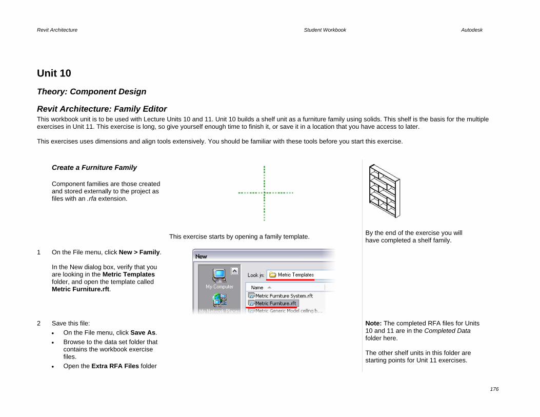
Revit Architecture Student Workbook Autodesk
176
Unit 10 Theory: Component Design
Revit Architecture: Family Editor This workbook unit is to be used with Lecture Units 10 and 11. Unit 10 builds a shelf unit as a furniture family using solids. This shelf is the basis for the multiple exercises in Unit 11. This exercise is long, so give yourself enough time to finish it, or save it in a location that you have access to later. This exercises uses dimensions and align tools extensively. You should be familiar with these tools before you start this exercise. Create a Furniture Family
Component families are those created and stored externally to the project as files with an .rfa extension.
This exercise starts by opening a family template. By the end of the exercise you will have completed a shelf family.
1 On the File menu, click New > Family. In the New dialog box, verify that you are looking in the Metric Templates folder, and open the template called Metric Furniture.rft.
2 Save this file: • On the File menu, click Save As. • Browse to the data set folder that
contains the workbook exercise files.
• Open the Extra RFA Files folder
Note: The completed RFA files for Units 10 and 11 are in the Completed Data folder here. The other shelf units in this folder are starting points for Unit 11 exercises.

Revit Architecture Student Workbook Autodesk
177
in this location. • Save this file as Unit 10 Shelf
Unit.
Note that the base routing for template search is on the Settings > Options > File Location tab. If you do not have the metric templates set as default or installed on your computer, you can start with the Metric Furniture.rft provided in the Extra RFA folder included with the workbook data sets.
The Family Editor opens. Note that the work environment is similar to the project mode. The design bar provides just one Family bar. The usual bars are not available (Site, Modeling, Structural, and so forth) because they are not used for family creation. The project browser is similar: there are plan views, elevations (which are named differently), and 3D views.
Create Overall Reference Planes When you are working with families, you are creating reference planes. These reference planes are assigned the parameters that drive the geometry.
3 In the project browser, open Floor Plans > Ref. Level. Right-click the horizontal reference plane. Click Element Properties.
In this view there are two reference planes. The intersection of these two planes represents the insertion point of the family. In this case, this point is the rear (back) and the middle of the piece of furniture. Begin by changing the name of this reference plane.
4 In the Properties dialog box: • Change the name to Back. • Verify that Is Reference: Back is
selected. • Click OK to exit.
Reference planes are important in the creation of families. It is on these lines that you base the parameters of your family; they are references for the geometry. Adding reference planes is easy. Simply specify a starting point and a final point (just like drawing a line). The length of the line symbol is not important. If necessary, you can resize it using the grips that appear at its ends when it is selected.

Revit Architecture Student Workbook Autodesk
178
A reference plane displays its name when selected. Naming your reference planes as you add them is a good idea.
5 On the design bar, click Ref Plane, and add three planes, as shown in image (don’t worry about the distance between each plane).
You must be able to vary the width and depth of your piece of furniture, so you add two new parameters to your family. To create a parameter you must add a dimension and assign it a label. The depth of the furniture family corresponds to the distance between the two horizontal reference planes; the width corresponds to the distance between the two vertical reference planes (right and left).
6 On the design bar, click Dimension. Add a dimension line between the two horizontal reference planes.
7 On the design bar, click Modify and select the dimension. On the options bar, Label list, select Add Parameter.

Revit Architecture Student Workbook Autodesk
179
8 In the Properties dialog box for the parameter: • Enter Depth as the name. • Verify that Type is selected. • Set the Group Parameter Under
option to Dimensions. • Click OK.
The Group Parameter Under setting is an organizational structure for the parameters.
A dimension that is associated with a label (parameter) displays the parameter name in the dimension string.
9 On the design bar, click Dimension. Add a dimension between the three vertical reference planes (click each line and position the dimension line with a left mouse-click). Click the EQ symbol that appears.
The vertical reference plane between the two other planes is the axis of the furniture. Thus, it must be equidistant between the planes on the right and left. To achieve this and keep it as a constant during the design, you need to add a dimension between the three reference planes and activate the equality constraint (symbol EQ).
10 Repeat the earlier steps to add the width parameter(shown far right): Add a dimension (between two outside vertical reference planes). Click the dimension. On the options bar, click Add Label. Set the label as follows: • Name = Width. • Group = Dimensions. • Type parameter.
Flex the Family

Revit Architecture Student Workbook Autodesk
180
11 On the design bar, click Family Types: • Change the Depth values to 400. • Change the Width values to 1200. • Click Apply. Click OK.
During family design, it is important to test the parameters to check that all is working properly. You have just added two parameters in your family. You can test them by changing some of their values. During this test, reposition the reference planes. You should not receive any error message. This is called flexing the family parameters.
12 Add a reference plane and parameter for height: • In the project browser, under
Elevations, click Front View. • Add a horizontal reference plane. • Add a dimension between the
reference plane on the ground and the one you have just added, and transform this dimension into a parameter named Height (also a type parameter in the Dimension group).
• Flex the family by changing parameter values in the Family Types dialog box.
Save your project.
Remember to save your work regularly. You can decide to create a new tree structure of files under the main Library folder. It’s a good idea to keep your personal libraries separate from the installed library.
Create Side Supports Now that the reference planes are in place, you create the side supports with the Solid Extrusion tool.
13 Activate the Ref. Level view. On the design bar, click Solid > Solid Extrusion.
Sketch mode is used for creating forms. The design bar displays the tools available to create the sketch, which must be a closed loop.

Revit Architecture Student Workbook Autodesk
181
14 On the design bar, click the Lines button. On the options bar, click Rectangle. Draw two rectangles, as in the image (the size is not important).
15 Use the Align tool to lock the left sketch line to the left reference plane, as in the image: • Click the Align tool. • Click left reference plane. • Click left line of the left rectangle
sketch line. • Lock this alignment by clicking the
lock icon to close it.
16 Repeat the process for the right rectangle, locking the right edge to the right plane.
17 Use the Align tool to lock the top left sketch line to the top reference plane, as in the image. • Click Align tool. • Click top reference plane. • Click top line of the left rectangle
sketch line. • Lock this alignment by clicking the
lock icon.
18 Repeat the process for the right rectangle’s top sketch line.

Revit Architecture Student Workbook Autodesk
182
19 Repeat this process for the bottom sketch lines, locking them to the lower reference plane.
The sketch lines shown here should now be aligned/locked with their respective reference planes.
20 On the design bar, click Dimension. Click the left reference plane, then the right line (which is not locked), and then position the dimension.
When you dimension a sketch like this, you want to run the dimension to the reference plane rather than the sketch line. This allows the sketch to flex as you use the dimensioned label parameters to drive the reference plane geometry.
21 Click the Modify tool. Select the sketch line on the right side of the rectangle you just dimensioned. Click the dimension text and change the value to 19 mm. Lock the dimension: • Click the dimension line to make
the dimension’s constraint lock appear.
• Click the dimension’s lock icon.
To get the lock to appear the dimension must be selected NOT the sketch line.

Revit Architecture Student Workbook Autodesk
183
22 Repeat this process for the sketch on the right side. Click Finish Sketch. Save the family.
23 Adjust the heights of the side pieces: • In the project browser under
Elevations, select Front view. • Select the 3D geometry (the solid
extrusions you just drew). Blue grips that can be used for dragging the faces appear.
• Drag the grip that allows changing of the height of the solid element until you reach the top reference plane.
• Click the lock icon to lock the alignment.
You can also use the Align tool to accomplish this task.
Because you drew two rectangles in Sketch mode, you have only one vertical grip that controls the height of both side frames.
24 The vertical sides are finished. Test your work by varying the parameters of the family (width, height, depth) in the Family Types window and clicking the Apply button (flexing the model). The 3D geometry must update consequently and no error message should appear. • To clearly see the effect of the
parameters, open a 3D view. • In the Workspace View Bar,
change the scale to 1:10.

Revit Architecture Student Workbook Autodesk
184
Note that as for all Revit Architecture views, a scale is associated with the view. You can use this scale to adjust the size of the text you see in the view as well as the profiling seen in 3D.
Add Reference planes for Shelves and Base
Like the side supports, you draw the reference planes first and then the solid extrusions for the base trim and shelves.
25 In the project browser, activate the Ref. Level view. Add a horizontal reference plane just above the one that defines the depth of the furniture family.
26 Add a new dimension line between the bottom reference plane and the one you just created. Select the reference plane and change the dimension text to 15 mm. Lock the dimension.
27 Open the front view. Add two horizontal reference planes, as shown in the image.

Revit Architecture Student Workbook Autodesk
185
28 Set the top dimension value to 34 mm and the bottom one to 50 mm. Lock the dimension lines.
29 Add four more reference planes, as shown in the image.
30 Click Dimension: • Click the four reference planes, as
well as the two created in the previous step.
• Click the EQ symbol. • Flex the model by changing
parameter values. Save the file.
A few words to explain these reference planes: two of them cannot move. They are constrained by locked dimensions (50 and 34). The other four are spaced regularly because of the dimension line that constrains the distance between them. Thus, if the height of a piece of furniture is modified, the top and bottom parts are fixed, whereas the distance between the four other planes is adjusted to satisfy the equality constraint.
Add Base Trim
31 Open the Ref. Level view. • On the design bar, click Solid
Form > Solid Extrusion. • On the design bar, click Lines. • On the options bar, click the
rectangle template. • Draw a rectangle, as shown in
image. The size is not important.

Revit Architecture Student Workbook Autodesk
186
32 On the toolbar, click Align. • Click the internal face of the
upright and then click the nearest line of the rectangle.
• • Lock this alignment by clicking the
lock icon to close it.
33 Repeat the process on the right side. Lock the alignment.
34 With the Align tool, click the upper of the two bottom horizontal reference planes and then click the nearest horizontal line of the sketch. Lock this alignment by clicking the lock icon to close it.
35 Add a dimension between the reference plane immediately above the one that defines the depth and then on the line that you did not lock. Select the line. In the dimension text change the value to 19 mm. Select the dimension and lock it. Click Finish Sketch.
Notice that when you finish the sketch, the dimension disappears.
It is still there when you edit the sketch. This is a useful way to keep your families free from extra dimension clutter but can make it difficult to track when a family gives you overconstrained errors.

Revit Architecture Student Workbook Autodesk
187
36 Open the front view. • Click Align. • Click the reference plane that is
directly below the top of the solid you just created, and then click the top of the solid.
• Lock the alignment by clicking the lock icon.
37 Flex the model. Save the family.
Add Shelves
38 Open Ref. Level. Rename the horizontal reference planes. • Right-click the lowest horizontal
reference plane. Click Element Properties.
• Rename the reference plane to Front of Case.
• Repeat, and rename the second reference plane Shelf Front.
• Click the top reference plane to verify that it is named Back. If not, repeat the preceding steps to rename it.
We refer to these reference planes now by these names.

Revit Architecture Student Workbook Autodesk
188
39 Open the Elevation Front view. On the design bar, click Solid Form > Solid Extrusion. On the design bar, click the Set Work Plane tool. • Set the work plane Name to Back. Click OK to return to the drawing window.
40 On the design bar, click Extrusion Properties. Set Extrusion End to 150 mm. Click OK to return to the drawing window.
You could set the depth of the shelves to 800 mm (or the numeric depth of your shelf) here, but doing so would not allow the shelves to flex as you changed the depth of the family. Changing it to 150 mm makes is easier to work with in plan view when you align and lock this front edge to a reference plane when you are finished with this sketch.
41 On the design bar, click Lines. On the options bar, click the rectangle template. Draw six rectangles, as shown in image. The size is not important.

Revit Architecture Student Workbook Autodesk
189
42 Click the Align tool. On the options bar, click Multiple Alignment. Click the interior face of the left upright. Click the left vertical lines of the rectangles (one at a time). Lock each alignment. (You must lock each line individually after aligning it.)
43 Repeat the process for the lines on the right side. Remember to lock the alignments.
These alignments allow the horizontal racks to remain in contact with the vertical uprights if the furniture family’s width is resized. You should now force the horizontal lines of the rectangles; the lines of the bottom of the rectangles must be respectively aligned with the reference planes that are subjected to the equality constraint. Then you need to place a dimension between each reference plane and the top line of the rectangles. Adjust and lock these dimensions to keep the thickness of the shelves consistent.
44 Click the Align tool. • On the options bar, clear the
Multiple Alignment option. • Click the reference plane above
ground level and then the bottom horizontal line of the lowest rectangle.
• Lock the alignment.
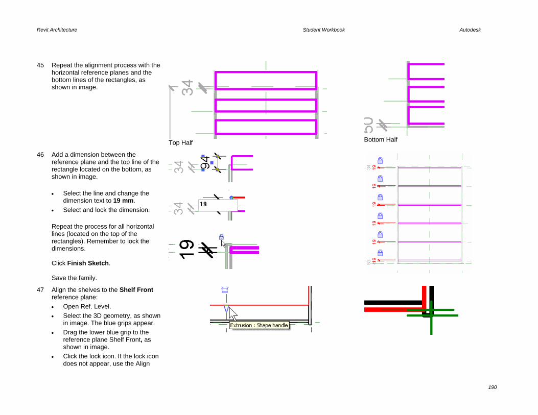
Revit Architecture Student Workbook Autodesk
190
45 Repeat the alignment process with the horizontal reference planes and the bottom lines of the rectangles, as shown in image.
Top Half
Bottom Half
46 Add a dimension between the reference plane and the top line of the rectangle located on the bottom, as shown in image. • Select the line and change the
dimension text to 19 mm. • Select and lock the dimension. Repeat the process for all horizontal lines (located on the top of the rectangles). Remember to lock the dimensions. Click Finish Sketch. Save the family.
47 Align the shelves to the Shelf Front reference plane: • Open Ref. Level. • Select the 3D geometry, as shown
in image. The blue grips appear. • Drag the lower blue grip to the
reference plane Shelf Front, as shown in image.
• Click the lock icon. If the lock icon does not appear, use the Align

Revit Architecture Student Workbook Autodesk
191
tool.
48 Flex the model. Save the family.
Add Vertical Supports
49 In the project browser, open the front view. Add two vertical reference planes, as shown in image.
50 Add a dimension line between the two reference planes you just added and the external ones, as shown in image. Click the EQ symbol.

Revit Architecture Student Workbook Autodesk
192
51 On the design bar, click Solid Form > Solid Extrusion. • On the design bar, click Lines. • On the options bar click the
rectangle template. • Draw six rectangles, as shown in
image. The size is not important.
52 On the toolbar, click Align. • On the options bar, select Multiple
Alignments. • Click the left reference plane (see
image) and align the three rectangle lines, as shown in image.
• Lock each alignment as you make it.
53 Repeat the process with the remaining rectangles and the right reference plane.

Revit Architecture Student Workbook Autodesk
193
54 Align bottom left support sketch line: • Click the Align tool. • On the options bar, clear the
Multiple Alignment option. • Align the bottom line of the two
bottom rectangles, as shown in image.
• Lock the alignment.
All these alignments are locked to maintain this constraint when you change the value of the width parameter of the furniture family.
Note that as you draw these rectangles, you can draw on top of the reference planes, and a lock appears. You can lock it at this time for the same effect.
55 Repeat the process with the top lines (see image).
56 Repeat the process for all the rectangles.
It is now necessary to manage the thickness of vertical separations. You operate in a way identical to the preceding stages, namely, a dimension locked between the reference plane and the unconstrained line of the rectangle. But before that, you align the sides of the rectangles between them (on the left and right).

Revit Architecture Student Workbook Autodesk
194
57 Align and lock the vertical supports to each other to establish a single control for the width of many elements: • On the toolbar, click Align. • On the options bar, click Multiple
Alignment. • Click the right vertical line of the
bottom-left rectangle, and then click the right vertical lines of the rectangles on top of it (see image).
• Lock each alignment as you make it.
58 Repeat the process for the rectangles on the right side.
59 Place a dimension line between the vertical lines of the bottom-left rectangle (see image). Select the line, and in the dimension text, change the value to 19 mm. Select the dimension and lock it. Repeat the process for the right rectangle. Click Finish Sketch.
Because the right sides of this set of rectangles are locked together, you need to place only one dimension to control all rectangles in that set.

Revit Architecture Student Workbook Autodesk
195
60 Open Ref. Level view. If the vertical supports are too narrow, select the 3D geometry and use the blue grips to align the bottom face, as shown in image. Lock the alignment.
61 Flex the model. Save the family.
The shelves are now ready to be used in a project. On your own, start a new project to insert this family. • On the File menu, click Load from
Library > Load Family. • Navigate to where you saved the
family and open it. • On the Basics design bar, click
Component. You can now place your family.
To test your new family in a project, you have to load it in a project. You can then insert it from the Component tool. Do not forget that your family is parametric! To find the parameters Width, Height, and Depth, open the type properties of the family.

Revit Architecture Student Workbook Autodesk
196
Unit 11 Theory: Propagation of Constraints
Revit Architecture: Alignment, Locking, and Constraints This unit is to be used with Lecture Units 10 and 11. Unit 11 builds on the family created in Unit 10. This unit has several exercises designed to illustrate various capabilities of the family within Revit Architecture. Exercise A: • Add the symbolic line representation to create the coarse, medium, and fine detail views. • Add a masking element to hide the floor pattern. • Use in-place family editing from the project environment. Exercise B: Add a material parameter to control the materials assigned to the shelf unit. Exercise C: Add a glass door and assign a visibility parameter to control the display of the glass element. Exercise D: Work with nested families to add a drawer unit to the family, using the parent shelf parameters to drive the geometry of the nested family. Exercise E: Fine-tune the family, adding control of family elements through the use of subcategories.
In this unit, you complete the furniture family created in the previous unit by adding more components to it. See image. The family that you created in the first part of the exercise requires more work so you can use it properly. You need to generate its 2D representation, associate all necessary materials, and define the levels of detail. Later in the exercise, you can experiment with nested families and formulas—an enormously powerful part of the Family Editor.

Revit Architecture Student Workbook Autodesk
197
Exercise 11A: In-Place Family Editing and Symbolic Line Representation In Unit 10 you worked with the Family Editor. In-place family editing provides access to the family definition directly from the project environment.
When you create a family, you need to define how that family behaves in different views (plan, section, elevation, 3D). The first important decision is its 2D representations: will the display of the family in plan view simply result from a cut 3D view, or should it be represented with a simple 2D sketch? In this case, it is not generated from the 3D model, but is represented with a 2D sketch that you create. After you have defined the way your family (object) is displayed in different views, you need to define its representation in different scales (coarse, medium, fine) for all views. So, this is your objective:
Coarse Medium Fine
Plan View
Section, Elevation, 3D View Display representation is generated from the 3D model (Solid Extrusion elements). You need to add two new sketch drawings to your family—one for its Coarse-Medium representation and one for the Fine representation. You use the symbolic lines for these sketches. You set the visibility of the objects in the family such that only the sketch lines display in the project and not the 3D elements of the shelf.
Masking regions are 2D objects such as a fill pattern that allows families to hide floor patterns and color fills when used in a project.
Open the Exercise Project In this exercise you edit the family directly from the project. You access the shelf from the 3D view.
1 Open m_Unit 11a – Start.rvt. Verify that the current view is Floor Plans: Level 2 Furniture. Zoom into the larger bedroom area. The shelf created in the last unit has already been placed in this project. In this project the shelf family is simply named mShelf.
The shelf has no symbolic lines. What is displayed in the drawing window is the solid form elements viewed from above (see note below).
Crop a 3D View Create a 3D view that has an active section box. Use section boxes to slice away parts of the model to show the interiors.
Symbolic Lines and View Detail Level
Masking Regions

Revit Architecture Student Workbook Autodesk
198
2 Duplicate the 3D view with the Dynamic View tool: • Set the 3D view current. • Press F8 to bring up the Dynamic
View dialog box. • In the Dynamic View dialog box,
click the disk icon. • Enter 2nd Floor 3D for the name. • Click OK.
This creates a new view in the project browser under 3D views.
3 Right-click in the drawing window. Click View Properties. • Select Section Box in the view
properties. • Clear the Crop View and Crop
Region Visible check boxes. • Click OK to return to drawing
window.
Turn on Shade mode if you want.
4 Cut the 3D view with the section box: • Click the section box that appears
in the drawing window. • Use the face grips to cut away the
south walls.
5 Apply a transparency override to the east wall: • Right-click the solid east wall. Click
Override Graphics in View > By Element.
• In the View-Specific Element Graphics dialog box, select Transparent
• click OK.
The wall still exists and is selectable in the view, but is now transparent.
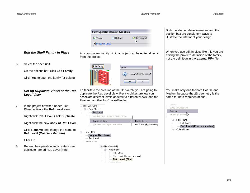
Revit Architecture Student Workbook Autodesk
199
Both the element-level overrides and the section box are convienent ways to illustrate the interior of your design.
Edit the Shelf Family in Place Any component family within a project can be edited directly from the project.
When you use edit in place like this you are editing the project’s definition of the family, not the definition in the external RFA file.
6 Select the shelf unit. On the options bar, click Edit Family. Click Yes to open the family for editing.
Set up Duplicate Views of the Ref. Level View
To facilitate the creation of the 2D sketch, you are going to duplicate the Ref. Level view. Revit Architecture lets you associate different levels of detail to different views: one for Fine and another for Coarse/Medium.
You make only one for both Coarse and Medium because the 2D geometry is the same for both representations.
7 In the project browser, under Floor Plans, activate the Ref. Level view. Right-click Ref. Level. Click Duplicate. Right-click the new Copy of Ref. Level. Click Rename and change the name to Ref. Level (Coarse - Medium). Click OK.
8 Repeat the operation and create a new duplicate named Ref. Level (Fine).

Revit Architecture Student Workbook Autodesk
200
9 Set view Ref. Level (Fine) current. Use the Drawing window view toolbar to set the detail level to Fine. Using the same method, assure that Ref. Level (Coarse - Medium) has Coarse set as view detail level in its properties.
10 Set view Ref. Level (Coarse - Medium) current. On the design bar, click Symbolic Lines. On the options bar: • Click the Arrow button (Select). • Select the Lock check box. Click the four lines shown in the image to create symbolic lines that are anchored and locked to the geometry of the shelf.
Selecting the Lock check box means that the selected lines automatically lock to the geometry from which they have been generated. You need to trim the symbolic lines you have just created. But because there is a lot of overlapping geometry, this can be a tedious task. To simplify it, Revit Architecture offers a temporary Hide/Isolate option to hide all 3D geometry, as well as the reference plane. You then have a pure 2D sketch drawing that is much easier to work with.

Revit Architecture Student Workbook Autodesk
201
11 Hide the vertical supports and reference planes: • Click the Modify tool, and select a
symbolic line that you just created. • On the Drawing window view
toolbar, select the Hide/Isolate icon.
• Click Isolate Category. The view is now in Isolate mode and shows
only the symbolic lines.
12 Clean up the lines: • On the Tools toolbar, click Trim. • Verify that the options bar’s mode is
set to Trim/Extend to Corner. • Trim the lines to close the
rectangle.
Adjust Visibility Settings You have just finished defining the 2D sketch for the Coarse - Medium level of detail. What remains is to tell Revit Architecture which lines should not be associated to the Fine level of detail.
13 On the design bar, click Modify. Select the line that represents the front of the furniture. On the options bar, click Visibility. In the Family Element Visibility Settings dialog box, clear the Fine check box. Thus the selected line is invisible in views set to this level of detail. Click OK.

Revit Architecture Student Workbook Autodesk
202
14 Activate the Ref. Level (Fine) view. Right-click in the drawing window. Click Zoom Fit.
15 Use the same methods to create the linework for the fine detail level: • Hide the Reference Plane category. • Add lines as shown: Symbolic lines
- Pick Lines – Lock. • Hide the solid geometry category. • Clean up the symbolic lines, as
shown. • Set the visibility of the new lines to
Fine only. • Click OK in the warning that
highlighted lines overlap.
Remember to use the Symbolic Lines Pick tool with the lock so the symbolic lines are related to the solid geometry. The solid geometry is driven by the family type parameters. If you just hide everything and draw the lines, they do not flex with the model.
16 Tile the screen so you have both views next to each other. Use Window > Close Hidden Windows before you use Window > Tile. This keeps all the windows you have open (which is often quite a few) from cluttering up the view
Note that even though the detail level is set to medium for the view, the symbolic lines that you set to not show in coarse or fine detail appear but are gray rather than black.
You see this behavior on all components within the family file. They do not disappear, but are gray instead of black. Once the file is loaded into the project, the lines behave as directed.
Flex the Family

Revit Architecture Student Workbook Autodesk
203
17 On the design bar, click Family Types. Modify the Width or Depth parameter. Note that the 2D geometry reflects the change and updates automatically.
18 Turn off the 3D solids in plan view: • Activate the 3D view, and select the
entire geometry. • On the options bar, click Visibility
and clear the Plan/RCP check box. • Click OK.
In Plan/RCP views you are going to use the 2D geometry you just created as representations for Plan/RCP. For all other ways, the representation is generated from the 3D model and in all levels of detail.
Reload the Family into the Project At this point you can either load the family back into the project or save the family out and overwrite the original RFA file. Or use the Save As command to create a new family based on these modifications.
19 On the design bar, click Load into Projects.
This loads the family into any projects you have open. If you have more than one project open, you are prompted to select which project to load it into (check i_Unit 11a – Start.rvt). If you have only one project open, it loads automatically without this prompt.
20 Click Yes to overwrite the existing version.
At this point your work has been transferred into the current project. You do not need to save the family you are working on, but you do need to save the project file.
21 Save the project.

Revit Architecture Student Workbook Autodesk
204
Note that each plan view has a cut plane. The default value for the cut plane is 4’-0”. Some families do not respect this cut plane when seen in plan view and display as though you were looking at them from the top. Likewise, when cut with a section mark they display an end view rather than a section. You can see which categories of model objects show correctly in plan and section by reviewing the categories in the Settings > Object Styles dialog box.
The Furniture Category has no Cut representation. Other family types such as generic models can be cut by a views cut plane or section clipping plane. The symbolic lines you have created in this family are now used as the default representation of the top view of the family.
22 In the plan view Level 2 Furniture, toggle the view detail level between coarse, medium, and fine.
Medium-level detail
Fine-level detail
Add a Masking Region Because you have turned off the visibility in plan view of the solid extrusions of the family, the floor shows through the family.
In this section you add a masking region to hide the floor below the shelf.
23 In the project file, click the shelf. On the options bar, click Edit Family.
Because the family is already open, it becomes the active file.
24 Set the plan view Ref. Level current. On the design bar, click Masking Region.

Revit Architecture Student Workbook Autodesk
205
25 Use the Lines tool and rectangle shape to draw a rectangle within the shelf area. On the design bar, click Finish Sketch.
26 Click the region. On the options bar, click Visibility. Under Detail Levels, clear the Fine check box.
27 Select the masking region. Use the blue grip or align tool to associate and lock the edges of the region to the reference planes of the family, as shown.
28 Set the plan view Ref. Level (Fine) current. On the design bar, click Masking Region. Use the Lines tool pick and lock options to follow the outline of the fine symbolic lines. Use the Trim tool to clean up the linework to match the images.
29 On the design bar, click Region Properties. Next to Visibility/Graphics Override, click the Edit button. Under Detail Levels, clear the Coarse and Medium check boxes.

Revit Architecture Student Workbook Autodesk
206
Click OK to return to the drawing window.
30 On the design bar, click Finish Sketch.
31 Load the family into a project and toggle the view detail level between coarse, medium, and fine.
Medium-level detail
Fine level-detail
32 Use the Window menu to change back to the shelf family. On the File menu, click Close to close the family file.
You do not need to save changes. They are already transferred to the project.
33 Save the project if you want. The remaining exercises in the unit work directly on the shelf family. You can use the family you developed here, or start with the RFA files provided with the exercise data sets.
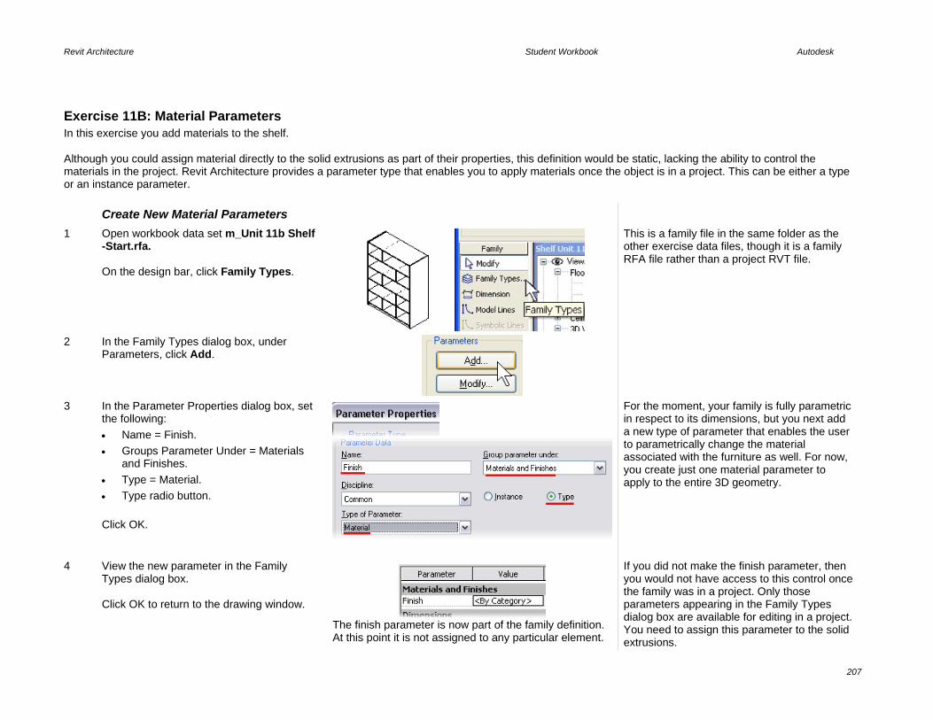
Revit Architecture Student Workbook Autodesk
207
Exercise 11B: Material Parameters In this exercise you add materials to the shelf. Although you could assign material directly to the solid extrusions as part of their properties, this definition would be static, lacking the ability to control the materials in the project. Revit Architecture provides a parameter type that enables you to apply materials once the object is in a project. This can be either a type or an instance parameter. Create New Material Parameters
1 Open workbook data set m_Unit 11b Shelf -Start.rfa. On the design bar, click Family Types.
This is a family file in the same folder as the other exercise data files, though it is a family RFA file rather than a project RVT file.
2 In the Family Types dialog box, under Parameters, click Add.
3 In the Parameter Properties dialog box, set the following: • Name = Finish. • Groups Parameter Under = Materials
and Finishes. • Type = Material. • Type radio button.
Click OK.
For the moment, your family is fully parametric in respect to its dimensions, but you next add a new type of parameter that enables the user to parametrically change the material associated with the furniture as well. For now, you create just one material parameter to apply to the entire 3D geometry.
4 View the new parameter in the Family Types dialog box. Click OK to return to the drawing window.
The finish parameter is now part of the family definition. At this point it is not assigned to any particular element.
If you did not make the finish parameter, then you would not have access to this control once the family was in a project. Only those parameters appearing in the Family Types dialog box are available for editing in a project. You need to assign this parameter to the solid extrusions.

Revit Architecture Student Workbook Autodesk
208
Associate the Family Parameter to the Properties of the 3D Geometry
5 Select all 3D geometry, and click Properties.
The material parameter is a hard-coded property of a solid extrusion. You need to assign to this property the family parameter Finish that you just created.
6 In the Element Properties dialog box, click the button to the right of Material.
7 In the Associate Family Parameter dialog box, select the Finish parameter. Click OK to close each dialog box.
If you want, you could create a new material within the Family Editor and associate it as the default material for the family. All materials created in the family are going to be automatically created in every project where this family is loaded. If an existing material has the same name, the family material is overwritten. That is why it is advisable to give your materials specific names.
8 On the File menu, click Save. Close the family.
On your own, start a new project and load your family. Insert a few instances of this family in the project and try changing their parameters. Note that all modifications are propagated in all instances of this family. This is because you have defined all family parameters as Type parameters.

Revit Architecture Student Workbook Autodesk
209
Exercise 11C: Visibility Parameters In this exercise you add glass doors to the shelf unit. You have now worked with two types of parameters. In this exercise you create two glass doors for the shelf unit. You create a new parameter in the family that is a Yes/No parameter type. Yes/No parameters have several uses. In this exercise you assign the Yes/No parameter to the visiblity of the glass doors. This enables you to turn them off in a project if you do not want to see them. They are still defined in the family, but not visible.
Parameter Type Name Assigned To Contols
Exercise 10 Length Width, Depth, Height Dimension Geometry
Exercise 11B Material Finish Solid extrusion properties Material assigned to the solid
Exercise 11C Yes/No Glass Door Solid extrusion properties Visibility toggle for element This exercise continues from the last exercise. If you worked through Exercise 11B, and were successful in both applying materials and manipulating the dimensions parameters, you can continue working on your family in this exercise. In this exercise you add and constrain new references as well as create solid extrusions and voids. Go back to Unit 10 if you need to review these tasks. Create Reference Planes for the
Door Pulls
1 Open Workbook data sets m_Unit 11c Shelf - Start.rfa. Activate the front view. Add the three new reference planes and dimensions shown in the image.
Families recognize logical conditions like Yes/No. You use that to control the visibility of the glass doors within the shelf unit. The next task is to create the geometry of the glass doors. These reference planes are used to locate the glass door handles later in the exercise.
2 Activate the Ref. Level (Fine) view.
To facilitate the creation of the glass doors, name one of the reference planes. The effect is to create a work plane on which you can trace your sketch of the doors. Just imagine you are inserting a sheet of paper on which you are simply drawing a sketch.

Revit Architecture Student Workbook Autodesk
210
3 Name a working reference level: • Activate the Ref. Level. • Select the horizontal reference plane
that is second from the bottom, named Shelf Front.
• On the options bar, click Properties. • In the Properties dialog box, change
the name to Glass. • Click OK.
4 Start the glass solid extrusion and set the Glass reference plane as the active work plane: • Activate the front view. • On the design bar, click Solid Form >
Solid Extrusion. • On the design bar, click Set Work
Plane. • In the Work Plane dialog box, select
Glass from the Name list. • Click OK.
5 On the design bar, click Lines. On the options bar, click Select. Select the Lock check box. Click the lines that form the first shelf, as shown.
For a sketch to be valid for an extrusion, it should not have T intersections and its lines must be in a closed loop. Since this is not the case for your sketch, you need to fix it.

Revit Architecture Student Workbook Autodesk
211
6 On the Tools toolbar, click the Split tool. On the options bar, click Delete Inner Segment. Click the bottom line at the intersection of the two middle vertical lines.
7 Repeat for the line above.
8 Click Trim. Set the trim mode to Trim/Extend to Corner.
9 Repeat for the other side.
10 Set glass thickness and visibility: • On the design bar, click Extrusion
Properties. • Set -8 mm for the Extrusion End (glass
starts on the interior side of the furniture).
• Click the Edit button next to Visibility/Graphic Overrides.
• Clear the Plan/RCP check box, as well
The value positive or negative when drawing an extrusion from a reference plane depends on the direction you first drew the reference plane (right to left or left to right). If you get it wrong here, you can always change it after you are finished with the sketch, by looking at the extrusion properties.

Revit Architecture Student Workbook Autodesk
212
as Front/Back (doors are not displayed in the plan or elevation view).
Click OK to return to the Element Properties dialog box.
11 Assign material to the solid extrusion: • Next to Material, click the <By
Category> box. Click the box that appears inside it.
• In the Materials dialog box, select Glass.
• Click OK to close each dialog box.
When you assign a material in this way, the material is static. You cannot assign a different material to the element placed in a project.
12 On the design bar, click Finish Sketch. Save the file (File > Save).
Create Pulls for the Glass Doors
13 Create the solid form sketch lines: • Click Solid Form > Solid Extrusion. • On the design bar, click Set Work
Plane. In the dialog box make sure that the active work plane is set to Glass.
• Select Lines, and on the options bar, click the circular shape. Activate the radius and set it to 20 mm.
• Add two circles, as shown on the right. Note that the center of insertion is the intersection point of the reference planes.

Revit Architecture Student Workbook Autodesk
213
14 Set extrusion thickness and visibility: • On the design bar, click Extrusion
Properties. • Set 30 mm as the extrusion end. • Click the Edit button next to Visibility
and clear Plan/RCP. • Under Detail Levels, select only Fine
(knobs are visible only in a Fine level of detail).
Click OK to close each dialog box.
15 Finish the solid form: On the design bar, click Finish Sketch.
Thus you are exiting Sketch mode, and you have finished creating the 3D object.
16 Reverse the extrusion: • Set Floor Plans: Ref. Level current. • Select Pulls. • On the options bar, set Depth = -30
mm (negative).
Assumptions about the start and end of the extrusions were opposite because the reference plane was drawn from left to right. A negative value extrudes toward the viewer, and a positive value extrudes away.
Depending on the direction you originally drew the reference plane Glass, your glass or pulls may be extruded to the wrong side. If so: • Select inversed element. • On the options bar, click Properties. • Set Depth = (Change the value from
negative to positive or vise versa). • Click OK.
You have access to this information from the Extrusion Properties on the design bar as you sketch the extrusion or after you finish the sketch from the object properties.
17 On the File menu, click Save (make it a habit to save your work often). Flex your family to test it.

Revit Architecture Student Workbook Autodesk
214
Create a Display Control Yes/No Parameter
In this section you create an instance Yes/No parameter and assign the glass door and the pulls to this parameter, enabling you to turn off these elements per instance when loaded into a project.
18 On the design bar, click Family Types. In the dialog box, under Parameters, click Add.
19 In the Parameter Properties dialog box set the following: • Under Name, enter Glass Door. • Group Parameter Under:
Construction. • Under Type, select Yes/No. • Click Instance (parameter can vary
from one piece of furniture to another). Click OK to return to the Family Types dialog box.
20 Verify that the parameter now exists as a family parameter. Click OK to return to the drawing window.
The glass door parameter appears, ready to be assigned to the visibility of an element. A checked box means show element, and a cleared box means hide.

Revit Architecture Student Workbook Autodesk
215
21 Assign the glass door visibility parameter to the doors and pulls: • Select the glass doors and pulls, and
click Properties. • In the Element Properties dialog box,
click the gray button at the right end of the Visibility/Graphics Overrides line. This button enables you to link one parameter to one property.
• In the Associate Family Parameter dialog box, select Glass Door.
Click OK to close each dialog box.
22 Save your work again. To verify functioning of this parameter, load the family in a project.
Start a new project, load your family, insert a few instances of the family in the project, and try modifying the parameters. The new, added parameter lets you control visibility of the glass doors and the doorknobs per instance. Try changing to different levels of detail in 3D view. The doors and knobs should display only in a fine level of detail. Try also changing the level of detail in plan view. There, regardless of the level of detail, the doors and knobs should not display.
Exercise 11D: Nested Families In this exercise you add drawers to the shelf unit. To create the drawers you first create a new furniture family and build a single drawer in it. You load this drawer family into the shelf unit family, “nesting” the drawer family in the shelf unit file. To finalize your family, you add two drawers in the opening between the glass doors. Instead of modeling it in the shelf unit family, you create a new family for the drawer and then insert it in this one as a nested family. The width of this interior space is determined by the overall width of the family type—or the width parameter. You create formula-type parameters that are based on the depth, width, and height parameters of the shelves and pass these parameters through to the nested drawer family. However, first things first: let’s create the drawer family.

Revit Architecture Student Workbook Autodesk
216
Note that the description for creating the drawer is less detailed than the previous one. If necessary, refer to the inital creation of the shelf unit to review the processes. Roughly, this exercise breaks down into the following sections: • Create a drawer family: This is a new family that you create. • Create a drawer shelf: This takes place in the shelf unit family and is a review of the Unit 10 exercise. • Create drawer parameters in shelf unit family. These drive the geometry of the nested drawer family. • Create formulas for the drawer parameters within the shelf unit family. The formulas perform arithmetic operations on other family parameters. • Load, place, and position a drawer. You can load other families to use inside families as components. • Link parameters from the shelf unit family to the drawer family. Create a Drawer Family
1 On the File menu, click New > Family. Select the Metric Furniture.rft family template. Click Open.
2 Activate the Ref. Level view (project browser, Floor Plans). • Set Scale to 1:10. • Add three reference planes, as
shown. • Add dimensions, as shown.
3 Convert the dimensions to labels (type parameters), as shown.
For equating parameters to dimensions see Unit 10.
4 Select the lower horizontal reference plane, and in its properties select: • Name = Front. • Is Reference = Front.

Revit Architecture Student Workbook Autodesk
217
5 Activate the front view: • Add another reference plane above
the existing one. • Add a dimension between the two
horizontal reference planes. Associate the dimension with a new parameter Height: • Group = Dimensions. • Type parameter.
6 Activate the Ref. Level view. Add a solid form using the extrusion method: • Draw with the rectangle sketching
tool. • Lock all sides to the reference
planes. At this stage do not click Finish Sketch.
Note that as you hold the cursor over an intersection of two reference planes, one or both of the reference planes are highlighted. If only one reference plane is highlighted, move the cursor slightly until both reference planes are highlighted. Then click the intersection. If you do this with both corners of the rectangle, the locks automatically appear.
7 On the design bar, click Extrusion Properties.
8 In the Element Properties dialog box, click the gray rectangle on the Extrusion End line. Select the Height parameter. Click OK to close each dialog box.
‘
The extrusion end (depth) is now dimmed because it is being driven by the height parameter. There is an equal (=) symbol here to let you know this has been assigned to a different parameter.
9 Click Finish Sketch.

Revit Architecture Student Workbook Autodesk
218
10 Create a void to cut away the inside of the box: • On the design bar, click Void Form
> Void Extrusion. • Draw a rectangle on the interior
side of the existing solid. • Using the Dimension tool, lock the
edges of the void to the reference planes (fix the distance to 10 mm).
At this stage do not click Finish Sketch.
It is a good practice to dimension to the reference plane rather than the geometry of the previous solid form.
11 Just as in the previous case, in the Extrusion Properties dialog box, associate the extrusion end to the height parameter and set the Extrusion start to 10 mm. This is the thickness of the bottom of your drawer. You can see this better in the front or 3D view. Finish the sketch.
12 Create a void for the pull: • Activate the front view. • On the design bar, click Void Form
> Void Extrusion. • Add a new sketch. This time it is a
circle cutting out the opening spot for the drawer. Draw the circle as shown on the right.
Don’t click Finish Sketch yet.
You need to assure that this sketch remains always aligned to the axis of the drawer width and that its vertical position doesn’t change either. To facilitate aligning a circle, activate the Center Mark Visible option and use it as a reference point for constraining.

Revit Architecture Student Workbook Autodesk
219
13 Click the Modify tool. Right-click the circle. Click Element Properties. Select the Center Mark Visible option. Click OK.
Note the cross in the middle of the circle. It is from this point that you define the constraints to the reference planes.
14 Using the Align tool, align and lock the circle to the central reference plane.
15 Add a dimension between the reference plane that defines the height of the drawer and the center of the circle. Set the distance to 30 mm and lock it.
16 In the Extrusion Properties dialog box, set the Extrusion Start to 0. Click OK. Click Finish Sketch.
The extrusion is heading the wrong direction. You need to fix that problem.
17 Open the Ref. Level view and select the void. Select the upper blue point and start sliding it toward the interior of the drawer. Lock that position. Lock the bottom triangular grip to the front face of the drawer.

Revit Architecture Student Workbook Autodesk
220
18 Finally, in the Family Types dialog box, add a new Material parameter. • Name: Finish. • Associate the entire 3D geometry
to it. • Group Parameter Under: Materials
and Finishes. • Type: Material. • Click Type. Flex the model to test your work. Try out different values for width, height, depth, and so forth. On the File menu, click Save As and save the family as Drawer.rfa. Close this file.
Note that a nested family can also be a shared family. Make a shared family by clicking Family Categories and Parameters on the Settings menu.
By selecting the Shared check box, you change the behavior of the nested family when it is loaded into a project. When a nested family is shared: • You can load the family directly into
a project to update all families that have that nested family.
• You can schedule the nested family
even though it resides in a different family.

Revit Architecture Student Workbook Autodesk
221
The drawer family is now ready to be inserted in the furniture family, but you need to make a few adjustments to the shelf. You are missing a small shelf that is positioned between the two drawers when placed in the opening.
There are no parameters in the shelf family that define the width, depth, and height of the drawer. You can resolve the first problem using the same techniques you used to create the shelf unit as well as the drawer. The second problem requires formulas to help calculate the values of the drawer parameters.
You create three new parameters: • Drawer Width = (total width / 3) – (2
x thickness of the separation panel) • Drawer Height = ((((total height – 84
mm) / 5) / 2) – 1 x shelf thickness) • Drawer Depth = total depth -15
Create Drawer Shelf in the Shelf Unit Family
19 Open workbook data set m_Unit 11d Shelf - Start.rfa.
The Unit 11D Shelf – Start.rfa is the end product of Exercise 11C. Use this as a starting point, or continue with a shelf unit you have tested in a project. Now add the separation shelf between the two drawers. To review how to do that, see Unit 10.
20 Activate the front view. On the design bar, click Solid Form > Solid Extrusion. Double-check that the active work plane is set to Back. Add a rectangular sketch in the upper part of the empty middle shelf, as shown in the drawing on the right.
21 Align the sketch and lock, as shown.

Revit Architecture Student Workbook Autodesk
222
22 Add a dimension for the shelf thickness. • Select the dimension chain, set it to
19 mm, and confirm. • Lock this dimension. • Click Finish Sketch.
23 Open the Ref. Level (Coarse – Medium), select the 3D geometry, and using the blue point in the front, align it to the second reference plane from the bottom (see image). Lock it to that position.
24 In the Properties dialog box for this geometry: • Associate the family parameter
Finish to element parameter Material.
• Click the Edit button next to Visibility/Graphic Overrides, and clear Plan/RCP.
Click OK to close each dialog box and return to the drawing window.
Create Drawer Parameters in Shelf Unit Family
Everything is ready to embrace the new nested family. The next step is to load the family you want to nest and correctly link its parameters to the parameters of the shelf unit.
25 On the design bar, click Family Types. Under Parameters, click Add and set the following: • Name = Drawer Width. • Group Parameter Under =

Revit Architecture Student Workbook Autodesk
223
Dimensions. • Type = Length. • Click Type radio button. Click OK to return to the Family Types dialog box.
26 Under Parameters, click Add and set the following Drawer Height parameter: • Name = Drawer Height. • Group Parameter Under =
Dimensions. • Type = Length. • Click Type radio button. Click OK to return to the Family Types dialog box.
27 Under Parameters, click Add and set the following Drawer Depth parameters:• Name = Drawer Depth. • Group Parameter Under =
Dimensions. • Type = Length. • Click Type radio button. Click OK to return to the Family Types dialog box.
28 Verify the parameters in the Family Types dialog box. Click OK to return to the drawing window.
The parameters have been created and are available for use.

Revit Architecture Student Workbook Autodesk
224
Create Formulas for the Drawer Parameters
29 Now, in the Family Types dialog box, in the Drawer Depth, Drawer Height, and Drawer Width lines, enter the formulas as shown in the image. For Revit Architecture to process the formulas you have just entered, it is necessary to respect case (for Revit Architecture, width isn’t the same as Width). The suffix "mm" is automatically added when you confirm your formula, so it’s not necessary to enter it. Click OK to confirm all.
Note that you can click Apply to test your formulas as you create them. Type the formula and click Apply. If everything is correct, the
calculated width shows up in the value column. Revit Architecture alerts you to any errors.
Change the base values such as width and height, keeping an eye on the resultant drawer width and drawer height.
30 Click OK to return to the drawing window. Save the family.
Load, Place, and Position a Drawer
In this section you nest the drawer family into the shelf unit family.
31 Load the drawer family into the shelf family: • On the File menu, click Load from
Library/Load Family. • Browse to find the drawer family
(you have to remember where you saved it).
• Click Open.

Revit Architecture Student Workbook Autodesk
225
32 Place an instance of the drawer in the shelf unit family file: • Set the Ref. Level view current. • On the design bar, click
Component. • Click anywhere in the drawing area
to insert one instance of the drawer family in the shelf unit.
33 Using the Align tool, do the following: • Click the center reference plane. • Click the axis of the drawer and
lock this alignment.
When you place the cursor in Align mode over the axis of the drawer, Revit Architecture displays a thick black line indicating the reference plane of the drawer family.
34 Align the front of the drawer to the second reference plane from the bottom (see image). Lock this alignment as well.
For a perfect match of the drawer family in the shelf unit, you need to link the parameters of both families.

Revit Architecture Student Workbook Autodesk
226
Link Parameters from the Shelf Unit Family to the Drawer Family
35 On the design bar, click Modify and select the drawer. On the options bar, click Properties.
36 In the Element Properties dialog box, click Edit/New to view the type properties of the element and thus the drawer parameters.
The element properties are the same properties you would expect to see if you loaded this family into a project.
37 Click the small gray box in the Depth line. In the Associate Family Parameter dialog box select Drawer Depth. Click OK. Repeat for all three parameters and associate them as follows: • Width = Drawer Width. • Height = Drawer Height. • Finish = Finish. Click OK to close each dialog box.
Use the small gray boxes at the far right of the Width, Depth, Height, and Finish parameters to make the link between the parameters.

Revit Architecture Student Workbook Autodesk
227
38 Activate the front view. Using the Align tool, align and lock the drawer in the upper empty space. If you have trouble selecting the lower line of the drawer, just position your cursor near that line and press TAB until that line is activated, then click to select it. (TAB is a great help whenever you have overlapping geometry.)
39 Switch to the Ref. Level view and repeat the same method to insert, align, and lock the second drawer. Switch to the front view and repeat, aligning and locking the second drawer vertically. Test the family by flexing the model.
Because all drawer parameters are type parameters, you do not need to repeat the same for the second drawer. The new drawer instance automatically inherits the instance properties of the existing one. All you need to do is align it in plan view and in elevation.
40 Select both drawers. On the options bar, click Visibility. Clear Plan/RCP. Click OK.
If you are daring, try copying the drawer in elevation instead of reinserting it in plan view. Can you get all the alignments in this front view?
41 Save your file. You are almost finished with your family. But before you use it in a project, you might want to add subcategories. With subcategories, you can control the entire display of the family in all views (line thickness, line color, line style, material, and so forth).

Revit Architecture Student Workbook Autodesk
228
Exercise 11E: Subcategories and Families The family category was defined when you selected the template to make it with. You can change this template later, but it is not advisable to do so. Always make sure to select the correct template when you create a new family. Next, you set new subcategories within your family. Create Subcategories of the
Furniture Category This exercise builds on work performed in previous exercises. If you have not completed the previous exercises, but want to work through this exercise on subcategories and families, open Workbook Data set m_Unit 11e Shelf - Start.rfa.
1 On the Settings menu, click Object Styles. Scroll down to the Furniture category. By default there is a predefined subcategory: Hidden Lines. You need three new subcategories: • Glass • Shelf • Accessories
2 Click New. • Enter Shelf for Name. • Under Subcategory Of, select
Furniture. Click OK.
3 Repeat the operation for Glass and Accessories.
For each subcategory, you can set whatever line thickness, color, or material you want. The material is assigned to the family subcategories only if under the Finish parameter the value is set to <By Category>. Here, you simply change the color of one of the subcategories.

Revit Architecture Student Workbook Autodesk
229
4 In the Object Styles dialog box, in the Shelf line, click the Line Color button. Select any color from the Color dialog box. Click OK.
5 To see just the symbolic lines, activate the Ref. Level (Fine) view. Using the Hide/Isolate tool, hide: • Reference planes. • 3D geometry. • Nested families. Select all these lines. • On the options bar, use the Type
list to change the lines to Shelf.
Assign Subcategories to Mask Objects
The masking objects within the family cannot be directly assigned a category in this manner, but must be assigned a subcategory in Edit mode.
6 Set the Ref. Level (Fine) view current. Hover your cursor over the edge of the shelf. Press TAB until you see masking object appear in the tooltip or at the status bar. Left-click to select the masking region.

Revit Architecture Student Workbook Autodesk
230
7 On the options bar, click the Edit button. Select all the linework. Use the Type list to change the subcategory of these lines to Shelf. Click Finish Sketch. Repeat for the Coarse detail masking region.
Assign Subcategories to Solid Extrusions
In principle, you can use the same method for both 2D and 3D, though the process is a bit different. For example, when you select a 3D solid, you cannot select the subcategory from the options bar Type list. Instead you must open the element properties for each solid and assign the subcategory there.
8 In a 3D view, select the glass doors. On the options bar, click Properties. Under Identity Data, set the Subcategory to Glass. Click OK to close each dialog box and return to the drawing window.
9 Repeat, assigning the following elements to their associated subcategories: • For all vertical separations,
horizontal shelves, and the plinth, associate the Shelf subcategory.
• For the doorknobs, click Accessories.
Save the family.
Use In-Place Family Editing to Modify the Drawer Family
Follow the same process you used in an earlier exercise to access the drawer family and modify the shelf in the project file.
As for the drawers, if you have tried associating a subcategory to them, you may notice that there is no subcategory

Revit Architecture Student Workbook Autodesk
231
parameter within their properties. The reason is that the drawers are nested families. So, go back to the drawer family to effectuate this.
10 Select a drawer, and on the options bar click Edit Family. Click Yes to open the family for editing.
In the next step you create a subcategory in the drawer family called Shelf (same as the subcategory in the family file). All geometry uses the existing shelf definition once it is loaded back into the family file.
11 On the Settings menu, click Object Styles.
Create a new subcategory Shelf.
12 Associate the entire geometry to this subcategory.
Alternatively, you could create a subcategory called Bin. In this case, when loaded into the shelf family, it would bring this subcategory with it and you would then have direct control over this subcategory in the shelf unit family file. Likewise, when you load the shelf unit into a project, it brings all the subcategories, including Bin. You would then have access to this subcategory in the project file.

Revit Architecture Student Workbook Autodesk
232
13 On the design bar, click Load into Project: • Check the current shelf family you
are working on. • Click OK. • Select Override Parameter Values
of Existing Types. • Click Yes to overwrite.
14 Close the Drawer family. At the Save Changes prompt, click No.
You can save the changes if you want. If you do so, the software tries to locate where the original drawer family file came from when it was loaded into the family.
You do not need to save because the changes have already been loaded into the shelf unit family.
15 You should now be back at the shelf unit family. Save the family.
The drawers assume the properties of the shelf subcategory defined in the shelf unit family.
Create Types The family is finished and is fully parametric. What you still can do is create types. In other words, you can preset different types of this family with predefined parameters such as width, depth, height, and material.
With types predefined, the shelf unit can automatically be inserted in various standard sizes or materials, enabling users to simply select the type from a list. Should the type not be found on that list, the user can always create it on the fly. This section shows how to do that.
16 On the design bar, click Family Types and then click New. As a name for the new type, enter 2100 x 1100 x 350 with Doors. Click OK.

Revit Architecture Student Workbook Autodesk
233
17 Change the corresponding values in the Family Types dialog box. Repeat, creating a new type 2100 x 1300 x 450 Without Doors and adjust the parameters to: • Width (1300). • Height (2100). • Depth (450). • Clear the Glass Door check box. Click OK. On the File menu, click Save.
Note: The glass door (visibility Yes/No parameter) is an instance parameter. You can set the default of any instance parameter in the family file. Any instances created with this type will have this setting by default. You will be able to change it by instance once placed in the project.
18 Start a new project or open an existing one. Load the new shelf unit family. Insert a few instances of it in the project. Note that in the unit’s Properties dialog box under Type, you see two or three different predefined types of this family.
The family name is displayed along with the type name. The family in this case is the name of the RFA file you have been working in.
19 Within a project file, change both the instance parameters (Glass Door) as well as the type parameters (width, height, and so forth). Remember that you do not see the door pulls unless the view is set to Fine.

Revit Architecture Student Workbook Autodesk
234
20 Activate Level 1 plan view. Right-click inside the drawing window. Click View Properties. Click the Visibility/Graphics Override Edit button. Expand the Furniture category. v
21 Click the empty box in the Projection Surface – Lines column in the Shelf line to override. Change the Line Color and the Line Pattern. Click OK.
22 Make sure the changes you have just made are propagated correctly.
23 Activate the 3D view. In the View Properties dialog box, click Visibility/Graphic Overrides. • Expand the Furniture category. • Clear Accessories. • Click OK.
Again, thanks to the subcategories, you can have an instance of this family in which the doorknobs are simply turned off and thus invisible. If you do not see the accessories in the view, remember these are set to view detail level Fine.

Revit Architecture Student Workbook Autodesk
235
24 Select any instance of the shelf unit: • Go to its Properties dialog box. • Click Edit/New. • In the dialog box that opens, select
Duplicate. • Revit Architecture prompts you to
enter a new name: you are about to create a new type of this family. Name this new type 210 x 110 x 350 – Red Finish.
• Click OK to close each dialog box. As a challenge, create a red paint material and apply it to the shelf.
You have just created a new type of this family.
You can create as many types of a family as you want and use them in any project.

Revit Architecture Student Workbook Autodesk
236
Unit 12 Theory: Interdependencies
Revit Architecture: Site This unit explains the Revit Architecture Site features and workflow as well as linking/importing files and AutoCAD drawings. This unit has four exercises. • 12A takes you through the process of importing an AutoCAD drawing. • 12B illustrates how to link a Revit Architecture project into a current project. • 12C works with the site tools to develop the model. • 12D exports a view and sheet into AutoCAD DWG format.
Exercise 12A: Importing AutoCAD Drawings In this exercise you start with the workbook template and import an AutoCAD drawing to use as a basis for the site work in the rest of this unit. This AutoCAD site drawing has polylines that are placed at elevation. In a later exercise you convert this geometry to a Revit Architecture toposurface. Import an AutoCAD Drawing
1 Start a new project with the workbook template.
Refer to Unit 1 if you need help creating a project from the workbook template.
2 On the File menu, click Save As and save your project as Unit 12.rvt in the Workbook data sets folder.
The exercises in Unit 12 build on this project. If you want to work through the exercises using this file, save it. Otherwise the starting point of each exercise has been provided for you, and you can use these files instead.
3 Set the Site view current. Duplicate the Site view. Rename the view Site ACAD.
You later use overrides to manipulate the drawing’s visibility in these views. Right-click in the project browser to duplicate and rename the view.
4 On the File menu, click Import/Link > CAD Formats.

Revit Architecture Student Workbook Autodesk
237
5 Browse to and click the drawing file Import Site Plan.dwg in the Workbook folder. Match the settings in the Import dialog box to the settings shown at right: • Clear Link (Instead of Import). • Clear Current View Only. • Click Preserve Colors. • Automatically Place: Origin-to-
Origin. Click Open to proceed with the import.
Notes on the Import/Link Dialog box: Link Instead of Import: This option maintains a live link to the drawing. If the drawing changes, you can reload the drawing with the changes into the Revit Architecture project.
Current View Only: It is a good idea to link drawings to a specific view. This approach cuts down on the amount of information that must be regenerated as you switch from view to view. For this exercise you import the DWG file into all views and use view control to turn the DWG file off in selected views.
Origin to Origin: Although you do not have access to the project origin as in AutoCAD software, the origin is near the intersection of the elevation marks.
6 Right-click in the drawing area. Click Zoom to Fit.
Control Drawing Layer by Query

Revit Architecture Student Workbook Autodesk
238
7 Click the imported DWG in the drawing window. On the options bar, click Query. Click one of the magenta lines in the drawing.
8 In the Import Instance Query dialog box, review the information about the line you just selected. Click Hide in View.
The AutoCAD layer in the DWG file is hidden in this view. The Query dialog box is a convenient way to find out information about the object you have selected in the drawing.
Layer Control of Drawing Instance: Visibility Graphics Override by View
In addition to the on/off control afforded by the Query tool, you have complete control over the linework in the drawing instance through the visibility graphics override of the view.
9 With the Site ACAD view current, type VG to access the view’s visibility graphics override.
10 Click the Imported Categories tab. Expand the Import Site Plan.dwg. Click the line style for C-CNTR-10 to access the override for this layer in the drawing instance. Set the line color to a purple or dark red and the line pattern to Long Dash.

Revit Architecture Student Workbook Autodesk
239
Click OK to close each dialog box and return to the drawing window.
The drawing now has overrides for this specific view.
Turn off Visibility with Graphic Overrides
11 Set the Floor Plans – Site view current. The overrides set in the Site ACAD view are not applied to any other views.
12 With the Site view current, type VG to access the view’s visibility graphics override. In the Imported Categories section, under Visibility, clear the Import Site Plan check box. Click OK to return to the drawing window.
The drawing instance is turned off for this view. You use these two views in the following exercises.
13 Save your project if you are continuing on, or just close it if you want to use the file provided for the next exercise.

Revit Architecture Student Workbook Autodesk
240
Exercise 12B: Importing Revit Architecture Projects In this exercise you continue from exercise 12A, but import a Revit Architecture project with a building in it. You then explore some of the display controls of the linked Revit Architecture file. If you completed the last exercise, you can continue to work in that file. If you choose to work in the provided project file, note that for consistency the AutoCAD drawing has been inserted rather than linked. Link a Revit Architecture Project
into the Current Project Revit Architecture files may be linked to one another. As the linked Revit Architecture file changes, it can be reloaded to update the current project with the new information. Also like the linked DWG file, you have control over how the linked Revit Architecture file is displayed in the current view.
Revit Architecture files import only as a linked file. Once they are in the project, however, you can bind them. Once a linked Revit Architecture file is bound, it becomes a model group in the current file.
1 Open the workbook file m_Unit 12b – Start. You should be in Site ACAD view.
2 On the File menu, click Import/Link > Revit. Browse to the workbook’s data set folder. Click m_Unit 12 Building.rvt.
3 In the Open dialog box, set: • Under Positioning, click
Automatically Place and Origin-to-Origin.
• Click Open.
Control Linked Project Display By View
You have several levels of control over the display of the linked Revit Architecture file. You can view the linked file with the default visibility of the view or the default settings of a view within the linked file, or override any of the linked constituent parts.

Revit Architecture Student Workbook Autodesk
241
4 Duplicate with detailing the Site ACAD view. Rename the new view Site-Concept.
5 Tile the Site ACAD and Site-Concept views.
6 Set the Site-Concept view current. Type VG to access the view’s visibility graphics override.
7 Click the Revit Links tab. Click the plus (+) sign to the left of m_Unit 12 Building.rvt. In the Display Settings column, click By Host View to override the default display settings.
If you have more than one instance of the linked file in your project, each instance is listed in this tree. You control the display of each instance independently.
8 In the RVT Link Display Settings dialog box, click the Basics tab. Click By Linked View. Set the linked view to Floor Plan: Level 1. Click OK to close each dialog box and return to the drawing window.
The linked file now uses the current display settings stored by the linked file rather than the host file’s current view settings.
Customize Linked Project’s Display by Object
You can also control each item in the linked file independently of the view settings stored in the linked project files view.

Revit Architecture Student Workbook Autodesk
242
9 With the Site-Concept view current, repeat steps 6 and 7 to return to the RVT Link Display settings.
10 In the RVT Link Display Settings dialog box: • Click the Basics tab. • Click Custom.
Setting the linked view’s override to Custom opens up all the override values in the list below it. These settings allow a general level of control based on settings in the host or the linked file. In addition to this control you also have access to the object categories in the linked project.
11 Click the Model Categories tab: • In the Model Categories list, select
<Custom>. • Click the Walls line. • Click the Cut Pattern’s Override
button. • Assign Solid Fill to this override. Do not close the dialog boxes yet.
If you click OK to return to the drawing at this point you would see the following:
All of the walls regardless of their type now display as a solid fill. But the door and window tags are still visible because they are part of the display of Floor Plan Level 1 in the linked drawing.
12 Click the Annotation Categories tab: • In the Annotation Categories list,
select <Custom>. • Clear the Show Annotation
Categories in This View check box.
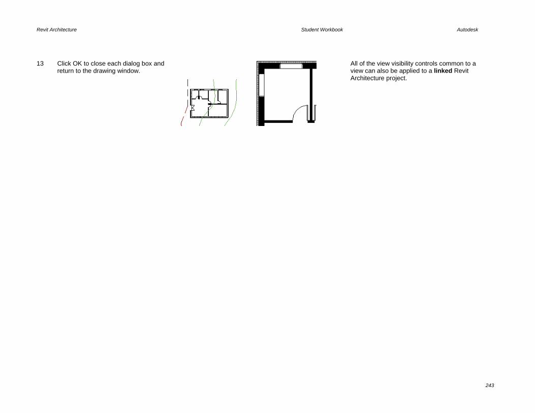
Revit Architecture Student Workbook Autodesk
243
13 Click OK to close each dialog box and return to the drawing window.
All of the view visibility controls common to a view can also be applied to a linked Revit Architecture project.
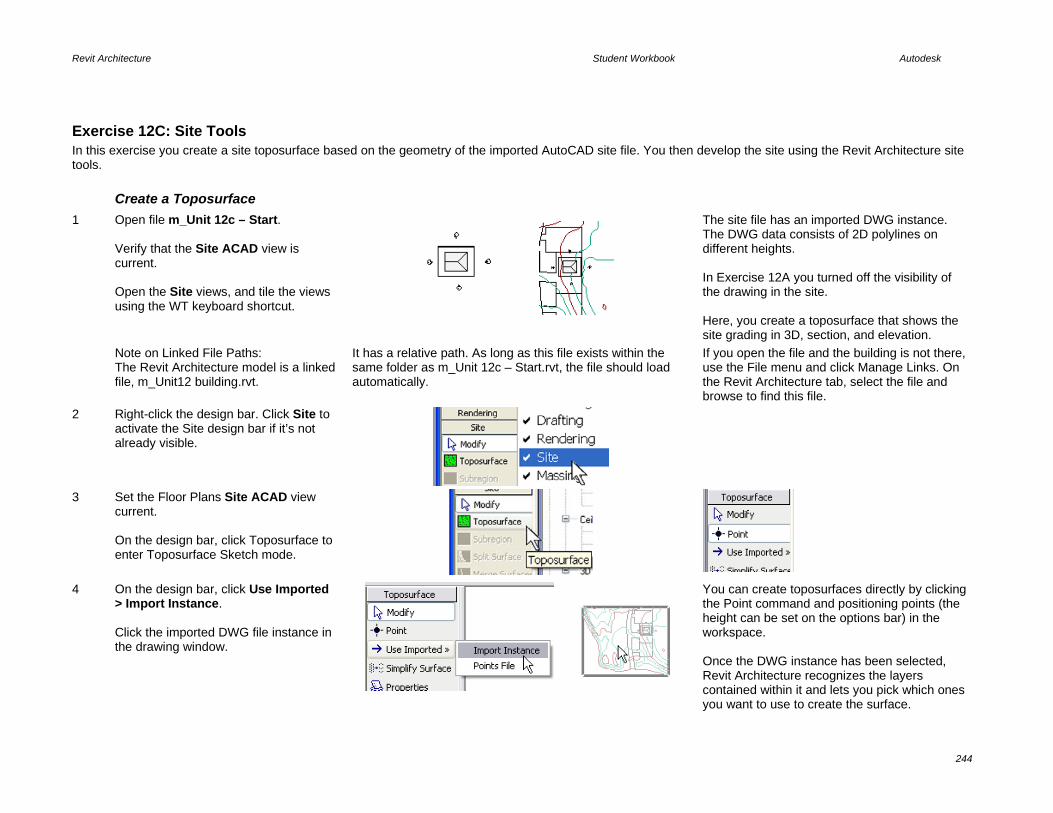
Revit Architecture Student Workbook Autodesk
244
Exercise 12C: Site Tools In this exercise you create a site toposurface based on the geometry of the imported AutoCAD site file. You then develop the site using the Revit Architecture site tools. Create a Toposurface
1 Open file m_Unit 12c – Start. Verify that the Site ACAD view is current. Open the Site views, and tile the views using the WT keyboard shortcut.
The site file has an imported DWG instance. The DWG data consists of 2D polylines on different heights. In Exercise 12A you turned off the visibility of the drawing in the site. Here, you create a toposurface that shows the site grading in 3D, section, and elevation.
Note on Linked File Paths: The Revit Architecture model is a linked file, m_Unit12 building.rvt.
It has a relative path. As long as this file exists within the same folder as m_Unit 12c – Start.rvt, the file should load automatically.
If you open the file and the building is not there, use the File menu and click Manage Links. On the Revit Architecture tab, select the file and browse to find this file.
2 Right-click the design bar. Click Site to activate the Site design bar if it’s not already visible.
3 Set the Floor Plans Site ACAD view current. On the design bar, click Toposurface to enter Toposurface Sketch mode.
4 On the design bar, click Use Imported > Import Instance. Click the imported DWG file instance in the drawing window.
You can create toposurfaces directly by clicking the Point command and positioning points (the height can be set on the options bar) in the workspace. Once the DWG instance has been selected, Revit Architecture recognizes the layers contained within it and lets you pick which ones you want to use to create the surface.

Revit Architecture Student Workbook Autodesk
245
5 In the Add Points from Selected Layers dialog box: • Click Check None to clear all the
layers. • Click to select only the layers Major
Contour and Minor Contour. • Click OK.
The contours of the DWG file are converted to the points that the Revit Architecture toposurface uses.
6 On the design bar, click Properties. Change the surface material to Site – Grass. Click OK. On the design bar, click Finish Surface.
You can change surface material later by opening its Properties dialog box.
7 Open a 3D view. Right-click the linked DWG (click one of the colored topography lines). Click Hide in View > Elements.
Note that the building is sunk inside the topographic surface. The DWG file is also visible in this view.
Create a Pad

Revit Architecture Student Workbook Autodesk
246
8 Set the Site ACAD view current. Set the view display mode to Wireframe.
9 Open the Visibility/Graphic Overrides settings for the view: • Click the Imported Categories tab. • Turn off visibility for all the DWG
layers except Site Layout. Click OK to close the Visibility Graphics dialog box. Click OK to close the View Properties dialog box.
Turn off the unnecessary DWG data in your view.
10 On the design bar, click Pad to enter into Sketch mode. Use the Lines tool to draw a rectangle around the parking area, as shown in the image.
11 On the design bar, click Pad Properties. Change the Pad Level to Level 1.
You can change this property at any time.
12 Click Finish Sketch.
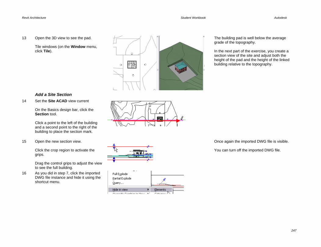
Revit Architecture Student Workbook Autodesk
247
13 Open the 3D view to see the pad. Tile windows (on the Window menu, click Tile).
The building pad is well below the average grade of the topography. In the next part of the exercise, you create a section view of the site and adjust both the height of the pad and the height of the linked building relative to the topography.
Add a Site Section
14 Set the Site ACAD view current On the Basics design bar, click the Section tool. Click a point to the left of the building and a second point to the right of the building to place the section mark.
15 Open the new section view. Click the crop region to activate the grips. Drag the control grips to adjust the view to see the full building.
Once again the imported DWG file is visible. You can turn off the imported DWG file.
16 As you did in step 7, click the imported DWG file instance and hide it using the shortcut menu.
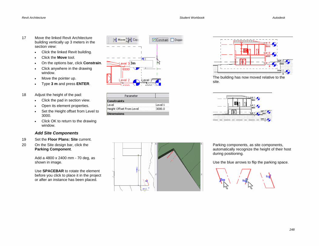
Revit Architecture Student Workbook Autodesk
248
17 Move the linked Revit Architecture building vertically up 3 meters in the section view: • Click the linked Revit building. • Click the Move tool. • On the options bar, click Constrain. • Click anywhere in the drawing
window. • Move the pointer up. • Type 3 m and press ENTER.
The building has now moved relative to the site.
18 Adjust the height of the pad: • Click the pad in section view. • Open its element properties. • Set the Height offset from Level to
3000. • Click OK to return to the drawing
window.
Add Site Components
19 Set the Floor Plans: Site current. 20 On the Site design bar, click the
Parking Component. Add a 4800 x 2400 mm - 70 deg, as shown in image. Use SPACEBAR to rotate the element before you click to place it in the project or after an instance has been placed.
Parking components, as site components, automatically recognize the height of their host during positioning. Use the blue arrows to flip the parking space.

Revit Architecture Student Workbook Autodesk
249
21 Select the parking component and array nine instances of it to the left (west): Click the parking stall. Click the array tool. On the options bar set: • Clear Group and Associate. • Number = 9. • Move to = 2nd. Click the right endpoint of the parking stall. Type SE to get the endpoint snap override. Click the left endpoint of the stall.
SE
Parametric arrays are helpful when positioning this kind of component.
22 On the Site design bar, click Site Component. Set the Type to Quercus Velutina - 8.2 Meters. Add a few tree components, as shown in image. The symbol used for plans, elevations, sections, and normal 3D is a simple stick symbol. When rendered, the AccuRender trees show foliage.
Trees are specific site components that have their own editor and can be customized, though Revit Architecture comes with an extensive tree library. To navigate through the library, create a new planting family and open the Family Types dialog box. Clicking the Plant Name parameter opens an AccuRender dialog box with the tree library.
Change the Site Settings
23 Maximize the site view. On the Settings menu, click Site Settings.

Revit Architecture Student Workbook Autodesk
250
24 The default setting are to show primary contours at intervals at 5 meters with secondary intervals every meter. Change the At Intervals Of field to 1000 (these are your primary contours). Change the Secondary Contours to 500. Click OK.
You can add more contours with the Insert button and assign the new contours with the Subcategory list. The Cut material defines what type of hatching the toposurface has. The poche base elevation setting in the bottom left defines how thick the surface displays in section views.
If you zoom in the finished drawing, you see that primary and secondary contours display with different lineweights, which are set in the Object Styles dialog box under the Topography category.
Add Contour Labels
25 Set the Site view current. On the design bar, click Label Contours and draw a straight horizontal line, approximately as shown in image.
You can draw the contour label line in any direction.
26 Zoom in to see the labels.

Revit Architecture Student Workbook Autodesk
251
27 Save the project if you are continuing on to the next exercise.
On your own, explore the Split Surface and Subregion tools.
Exercise 12D: Exporting AutoCAD Drawings In this exercise you export the site model and a sheet for use with AutoCAD software. Place Views on Sheet
1 Open file m_Unit 12d – Start. 2 In the project browser, right-click the
Sheets (All) category. Click New Sheet. Click OK to accept A1 metric as the title block.
Exercise 5A covers the basics of sheet creation. Here you just add the Activate View feature of sheets.
3 Left-drag the view Site Concept and drop it onto the sheet view.
Any view without an active crop region defaults to the model extents when placed on a sheet.
Work with Views on Sheets In this section you activate the view on the sheet. Activating a view opens the view for editing as if you had made that view current with the project browser.

Revit Architecture Student Workbook Autodesk
252
4 Right-click the site plan. Click Activate View.
When you activate the view the other views are dimmed.
5 Right-click in the drawing window. Click View Properties. • Select the Crop Region Visible
check box. • • Click OK to return to the drawing
window.
6 Click the crop region, and drag the double blue arrows back into a reasonable location around the information in the view. When you are finished, right-click anywhere in the drawing window. Click Deactivate View.
The sheet view is returned to its normal state, but the view title line is not automatically updated.
7 Click the title line and drag it into location. Click the view’s crop region. Grip the title line ends into place.
Whether this is faster to do in the view or in the sheet depends on how many views are in the project, and how fully you have developed your sheets.

Revit Architecture Student Workbook Autodesk
253
8 Prepare and add Section 1 view to the sheet: • Open Section 1 view. • Change the scale to 1:100. • Drag the crop regions in as shown. • Change to Shading mode. • Drag the view onto the sheet.
The finished sheet is now ready to export to AutoCAD software.
Export a Sheet to AutoCAD Drawing Format
Before you export to AutoCAD, verify that the export settings are correct.
9 On the File menu, click Import/Export Settings > Export Layers DWG/DXF.
10 Make any changes needed to the export settings.
Each Revit Architecture object is assigned a layer and color ID for instances where the object is cut (such as a wall in plan view) or as projection (a wall in elevation). The layer names are created automatically in the new drawing file. The color IDs are the standard AutoCAD ACI colors that are assigned to the layers as they are created.
Note that by clicking the Load button, you have access to several different preset export layer files.
The Standard button enables you to change the standards also.

Revit Architecture Student Workbook Autodesk
254
11 Click OK to return to the drawing window.
12 On the File menu, click Export > CAD Formats.
13 In the Export dialog box: • Under File Naming, click Manual. • Type a file name for the drawing. • Verify that AutoCAD is the format to
save to.
You can use the export range to export multiple views and sheets. If you do this, then the Manual button is not selected.
You can fine-tune the export to DWG by clicking the Options button.

Revit Architecture Student Workbook Autodesk
255
14 Click Save to create the new drawing file.
The new drawing is created along with a PCP file for the pen settings that AutoCAD can use to plot this file.

Unit 14 Theory: Detail
Revit Architecture: Drafting and Linework This unit explains how to create a detail using Revit Architecture.
1 Open the file m_Unit 14 – Start.rvt in the Training Files directory. Verify that the view Floor Plans: Level 2 is current.
2 On the Basics design bar, click Section. On the options bar, set the following: • Section Type = Detail View: Detail. • Scale = 1:10.
You can create as many section types as you want by duplicating them. In the project browser, details (including sections) appear under the category called detail views, while other section types have their own category. The scale affects the detail level of the new view. Normally, all views 1:5 and bigger have detail level set to Fine, but it is possible to change the settings by clicking Detail Level on the Settings menu.
3 Draw a section mark over the window, as shown in image. Open the section by deselecting the mark and double-clicking the detail bubble, or use the project browser.

Revit Architecture Student Workbook Autodesk
257
4 Click the crop region, and use the grips to resize the detail to show the floor above.
You may need to resize section views, or maybe even turn off the crop region if it disturbs your drawing: right-click in the drawing window, click View Properties, and clear Crop Region Visible.
5 Right-click in the section detail view. Click View Properties. • Click the Visibility/Graphics Override
Edit button. • Under Model Categories, turn off
visibility of windows. • Click OK to exit the dialog box. • Click OK again to close view
properties.
The keyboard shortcut for displaying the visibility settings for the view is VV. It provides a quick way to jump directly to the dialog box.
6 On the File menu, click Load from Library > Load Family. Navigate to the folder where you placed the workbook data set files. Open the folder Extra RFA Files and select the file called Window Section.rfa. This detail component was generated from a DWG file.
Detail components can be created by drawing directly or by importing a DWG, DXF™, or DGN file if you already have the detail in one of these file formats.
7 On the Drafting design bar, click Detail Component. The loaded Window section detail component should be ready for placement in the drawing.
Annotations and detail components are view specific: they are visible only in the view in which they are added.

Revit Architecture Student Workbook Autodesk
258
8 Place the window detail component as shown in image. Use the Align tool to align it to the sill. Use the Align Tool to align it with the wall finish.
While using the Align tool, use TAB to cycle through the align target locations to select the wall sill if it does not select automatically.
Edit Cut Profile
9 On the toolbar, click the Edit Cut Profile icon. On the Options bar, verify that Edit Face is selected.
10 Click the hatch or boundary of the subcomponent you want to modify.
This takes you into Sketch mode, where you draw the linework for the new cut profile of the component.
11 Use the Lines tool to draw a new profile where you want the subcomponent to be cut. Click the blue arrow toward the side you want to keep. Click Finish Sketch.
You must repeat the process with each of the components in the wall.
12 Repeat the process for the other three wall components that interfere with the shade roller mechanism.
The profile of each material must be edited separately because the tool works on one hatch at a time.

Revit Architecture Student Workbook Autodesk
259
13 On the Drafting design bar, click Repeating Detail. On the options bar, click Repeating Detail: Brick. • Click near the upper floor. • Click near the top of the window. • Click the Modify tool.
Use detail components in arrays to create a repeating detail, or you can use the repeating detail tool. A simple example is a series of bricks in section view. There are various ways to assemble the detail component in a repeating detail.
14 Select the new brick detail. • Click the Move tool. • Select the bottom corner end point. • Move the brick detail into place.
15 Add another Brick – Section repeating detail below the window.
Note that this brick detail component contains an invisible line that defines the width of the mortar. You could add a hatch in the detail component so it displays the mortar in the repeating detail.
16 If the brick repeating detail is in front of the window detail, select the former, and on the options bar, click the Bring to Front icon.
It is possible to define the order of their appearance by using the toolbar displayed on the left. This toolbar appears on the options bar once a detail component has been selected.

Revit Architecture Student Workbook Autodesk
260
17 On the Drafting design bar, click Insulation, and, on the options bar, set the size to 150 mm. Draw the insulation in the exterior wall, as shown in image, both above and below the window detail.
Change the insulation width after designing it by right-clicking it and clicking Properties > Width Field, or simply by changing the Width value on the options bar.
18 Save and close your project.

Revit Architecture Student Workbook Autodesk
261
Unit 16 Theory: Is Architecture Engineering?
Revit Architecture: Formulas This exercise starts with a data set that is a window family. Families are created using family template files that contain different parameters according to the category. In this window family a crown subcategory was added in the Object Styles dialog box (Settings menu, Object Styles command). The window family is already complete; you add some formulas to control the geometry and visibility of some of the solid elements that compose the window family. In particular, you create the following: • Formulas that control the relative height of the frames (and the glass) depending on the sill thickness. • A formula that controls visibility of the crown, to be displayed only if the window width is equal to or larger than 1400 mm. Parameter values should always be changed in the Family Types window to verify whether the model flexes correctly. In Unit 11 you added formula parameters to control the width of the drawer of the shelf unit. You also added a visibility parameter to control the visibility of the glass doors. In this exercise you combine these types of parameters to create formulas and tie the display of the crown or lintel of the window to the result of the formula. This exercise assumes you have worked through the exercises in Units 10 and 11. If you have questions about terminology or processes, you can go back to those exercises for review. Explore the Window Family in the
Project In this section you explore the existing parameters set up in the window family.
1 Open file m_Unit 16 – Start.rvt.
Set current 3D Views: {3D}. Click the window in the view.
2 Note that there are already a few types defined with the family. Select them from the list. Return to the type named 1200 x 1200 mm.
As you flex the types in the project, note that for the different heights the relationship between the sill and the window frame remains constant.

Revit Architecture Student Workbook Autodesk
262
3 Open the type parameters (the Edit/New button in the Element Properties) for the 1200 x 1200 mm window type. Change the sill thickness to 100 and click Apply. Do not close the type properties dialog box yet.
Note that when you do this, the H parameter changes as well. The current definition of the H parameter is a formula; height (of the window opening) less the sill thickness. The relationship between the sill and the window frame is constant.
4 In the Type Properties for the window, clear Sill Visible. Click OK to return to the drawing window.
The window has a gap where the sill is still taken into consideration, but is not displayed.
Edit the Window Family In this section, you add a formula to control the relative frame height according the sill visibility.
5 Click the window. On the options bar, click Edit Family. Click Yes to edit the family.
Formulate the H Parameter Sometimes parameters are buried in the sketch of a solid or void. The next step drills into the sketch mode to illuminate the location of the H parameter you modify later in the exercise.
6 The H parameter was specifically created and assigned to the frame height. To see how it is defined: • Select the outer frame. • On the options bar, click Edit
Sweep. • On the design bar, click Sketch 2D
Path. • Go to the exterior elevation view. On the design bar, click Quit Path. On the design bar, click Quit Sweep to return to the standard family editor
Note the gap from the bottom of the sketch line to the opening in the wall to allow for the sill.
If you see a parameter in a family definition that is not immediately evident when the family is opened, there is a good chance that it is nested into the Sketch mode of a solid element of the family.

Revit Architecture Student Workbook Autodesk
263
window.
7 In the Family Types Properties dialog box, click the H Parameter row. Under the Formulas column, replace the formula Height-Sill Height with the IF formula: if (Sill Visible, Height - Sill Thickness, Height).
The formula syntax is: IF (<condition>, <result-if-true>, <result-if-false>) Because Sill Visible is a Yes/No parameter, you only need to type the condition by itself. Formulas and parameters are case sensitive.
To put this into plain English: If the sill is visible (condition is true), then Height - Sill Thickness (raise the frame for the sill). If the sill is not visible (condition false), then use the value held by the Height parameter as the height of the window, filling in the space that would otherwise be occupied by the sill.
8 Click Apply. Change the Sill Thickness parameter to different values. Click Apply each time you change the value. Note how the height of the window frame now changes correctly.
Always flex your family from the Family Types dialog box to make sure the model responds correctly.
9 Clear the Sill Visible parameter. Click Apply. Note how the frame resizes accordingly to fit precisely in the opening.
Note that the sill is still visible in the model but is dimmed. In the Family Editor even if visibility of a specific component is turned off, you still see it for editing purposes. In the normal project environment, the sill would not be visible.
Create Crown Visibility Parameter In the last section you controlled a length parameter by the visibility Yes/No parameter. In this section you do the opposite and control a visibility parameter based on a length.
If the window width is greater than a specified width, show the Crown/Header. If it is less than the specified width, do not show it.
10 You next create a visibility parameter to control the crown visibility. Click the Add button under the Parameters category in the Family Types dialog box.

Revit Architecture Student Workbook Autodesk
264
11 Create a new Yes/No parameter called Crown Visible (see image on the right). Click OK to return to the Family Types dialog box. Click OK again.
Refer to Units 10 and 11 for basics on creating new parameters if you have difficulty with this.
12 Select the solid that acts as the crown. Open its Properties dialog box by right-clicking Properties or by clicking the Properties icon on the options bar.
13 Click the gray icon at the right end of the Visible row of its properties.
Clicking the button enables you to assign control of that element parameter to an equivalent family parameter that can then be either used in formulas or changed directly in the project.
14 Assign it the Crown Visible parameter, which you created in the previous step. Click OK to close each dialog box.
The family parameters displayed are only those of the same type: length parameter if you are setting a distance, Yes/No if you are selecting a visibility parameter, material if you are assigning a material parameter, and so on.

Revit Architecture Student Workbook Autodesk
265
15 Open the Family Types dialog box. Under the Crown Visible parameter row enter the formula: or(Width>1400 mm, Width=1400 mm)
Formulas are case sensitive. It’s a good idea to type the unit suffix in formulas directly to avoid confusion.
16 Change the window type from the active one to 1400 x 1400 mm. Note the changes in the Crown Visibility. Click OK.
Load the Window Family into Project
17 On the design bar, click Load into Projects. Select the Override Parameter Values of Existing Types check box. Click Yes.
If you have more than one project open, click the m_Unit 16 project you started the exercise with. Click OK.
Flex the Family in the Project
18 Turn off the sill in the window’s type properties. Change the window to different types.
The frame now fills in the full height when the sill is turned off.
19 Use the Window menu to change back to the window family.
20 Close without saving the family. The family is already loaded into the project. You can save it as a different family or just

Revit Architecture Student Workbook Autodesk
266
close it without saving. 21 Save the workbook unit exercise RVT
file if you want.

Revit Architecture Student Workbook Autodesk
267
Unit 17 Theory: Databases
Revit Architecture: Databases In this exercise you export a Revit Architecture project to an ODBC-compliant database. Export a Database There is no data set provided for this exercise. You can
start with one of your own projects or any of the workbook data set project files.
You can export any Revit Architecture project file to an ODBC-compliant database for interaction with other software programs
1 Open a project. If you are not working on your own project, open one of the projects provided with the workbook. On the File menu, click Export ODBC Database.
ODBC stands for Open Database Connectivity. The purpose is to create a database that can be used by any database management system regardless of the application. Part of an ODBC-compliant database is a data source name file. This file is like a translator to the database and provides a link between the database and the software used to interpret the data. In this exercise, you create both an access database (MDB) file and the data source name file.
2 In the Select Data Source dialog box, click New.

Revit Architecture Student Workbook Autodesk
268
3 Click the Microsoft Access Driver. Click Next.
4 In the Create New Data Source dialog box: • Click Browse. • Browse to the workbook’s data set
folder. • Name the file. • Click Save. • Click Next. • Click Finish.
You should now be looking at the ODBC Microsoft Access Setup dialog box.
5 In the ODBC Microsoft Access Setup dialog box, click Create. Enter a name for the database. Verify the location where you want to create the database. Click OK.

Revit Architecture Student Workbook Autodesk
269
6 Click OK again.
7 Click OK again.
8 Click OK again. The database has been created in the folder you specified. This sample is provided in the Completed folder of the workbook data sets.
9 Click OK again.

Revit Architecture Student Workbook Autodesk
270
Unit 18 Theory: Schedules, Tables, and Legends
Revit Architecture: Tags, Schedules and Legends Schedules are just another view of the building model, but instead of representing the data in a graphical format, the information in the building database is presented in tabular format. The seven exercises in this unit cover the scheduling capabilities of Revit Architecture. Each covers a different aspect of schedules in the Revit Architecture environment. 18A: Door schedules. 18B: Room objects schedule and tags. 18C: Calculated values in a room schedule. 18D: Room finish keys. 18E: Color fill legends. 18F: Symbol legends. 18G: Material takeoff schedules.
Exercise 18A: Door Schedules In this exercise you create a door schedule, modify its properties, and place it on a sheet. Create a Schedule
1 On the File menu, click Open. Browse to the file m_Unit 18a – Start delivered with the workbook and open it. On the View design bar, click Schedule/Quantity. In the New Schedule dialog box, Category list, select Doors. Click OK to proceed to defining the schedule properties.
The file opens with a 3D view of the building. The active view doesn’t have an effect on the creation of the schedule table. You can make a schedule table of any object in the model. There are two ways to make a schedule table: using the Schedule button on the View design bar or the View menu, New > Schedule Table command.

Revit Architecture Student Workbook Autodesk
271
2 In the Schedule Properties dialog box under Available Fields, click Family and Type. Click Add.
The Available Fields list contains all information that can be extracted from the door object. On the right is an empty list in which you are going to add the information that you want to see displayed in the schedule table.
3 The Family and Type field is now moved to the right, under Scheduled Fields. This is now one of the columns in the schedule. Repeat for two other fields: Width and Height.
The order of the fields determines the order of the columns in the schedule table. You can easily modify this order using the Move Up and Move Down buttons.
4 Click OK to close the Schedule Properties dialog box. The schedule table is displayed in table form.
Every line in the schedule table represents a door within the project. You might think this is an odd way to represent a door, but Revit Architecture can represent an object in a textual manner, showing all important information about that object.
You can change the appearance of your schedule table by adjusting the width of the columns. The principle is simple: just drag the separation line between two columns in the title to the desired width.
5 Right-click the schedule table. Click View Properties.

Revit Architecture Student Workbook Autodesk
272
6 In the Element Properties dialog box, click the Edit button next to Sorting/Grouping.
7 In the Schedule Properties dialog box, under Sort By, select Family and Type. Click OK to close each dialog box.
The schedule table displays correctly according to the sorting criteria you have defined. Revit Architecture allows four levels of sorting.
Before you continue working on your door schedule, you need to analyze the possibilities that Revit Architecture proposes at this stage. Let’s look at the options bar.
8 Click in any schedule table field. Click Show. Revit Architecture opens a view in which you see a graphical representation of the selected door.
You can achieve the same by right-clicking the schedule field, and then clicking Show.
9 Click Show several times. Click Yes in the Search prompt.
Revit Architecture enables you to search for other views in which this door is displayed. To do that, click Show. Should you not want to continue, simply click Close.

Revit Architecture Student Workbook Autodesk
273
10 Click again in any schedule table field. On the options bar, click Delete. Read the message, and then click Cancel.
Revit Architecture double-checks that you really want to delete that instance so you have a final choice of accepting (OK) or canceling. Again, you can find the same command by right-clicking and using the shortcut menu.
Note that schedule table cells are editable. You can change any value in the schedule table (for example, the width of the door). You should be careful when doing this, however, because the door width is a type parameter, which means you would change the width of all instances of this type in the project.
Finally, you can change the family and type by simply clicking the Family and Type field. This field contains a list from which you can select the desired door family or type.
It is important to understand that no matter what changes you undertake in the schedule table, they are populated everywhere in the project.
The opposite works as well. If, for example, you delete or add a door in the project, the door is automatically deleted or added in the schedule table. In the Revit Architecture model, the schedule tables are always directionally synchronized with the project.
You are now going to work further on your schedule table, refine it, add new fields, sort it, modify its parameters, and finally place it on a layout sheet.
Add Counts and Totals to Schedule

Revit Architecture Student Workbook Autodesk
274
11 Right-click the schedule table. Click View Properties. In the Element Properties dialog box, next to Fields, click Edit.
You have now set all necessary fields. Next you sort your schedule table to make it more usable. Revit Architecture enables you sort with four different criteria simultaneously. Here, you want to sort by level and then by family and type.
12 Add the fields Count and Level. Reorganize them as shown in the image using the Move Up and Move Down buttons.
13 Click the Sorting/Grouping tab.
On the Sorting/Grouping tab you find the criteria set previously. You need to change them. You want to sort this time by level and then family and type. Because there are two criteria for sorting,use the header and footer to provide additional structure to the schedule.
14 On the Sorting/Grouping tab, set the following: • In the Sort By field, select Level. • Select the Header and Footer
check boxes. • In the list next to Footer, select
Count and Totals. • Select the Blank Line check box. Do not close this dialog box.

Revit Architecture Student Workbook Autodesk
275
15 In the Then By field, select Family and Type. • Select the Header and Blank Line
check boxes. • Click OK to close each dialog box.
As a result of the criteria you defined, you find doubling parameters. For example, you can see the Header M_Double: 1640 x 2000 mm in every row of the door, but it’s the same for the level as well. This isn’t a problem, because Revit Architecture enables you to hide fields you don’t want to be visible.
Hide Columns in the Schedule
16 Right-click the schedule table. • Click View Properties. • In the Element Properties dialog
box, Formatting field, click Edit.
17 Verify that Family and Type is selected. At the bottom of the dialog box, select the Hidden Field check box. Click OK to close each dialog box.
As you can see, those fields are not displayed. However, notice that the schedule table displays every instance of your doors, but you need to know the total number of doors of the same type. So, you need to fix that final problem.

Revit Architecture Student Workbook Autodesk
276
18 Right-click anywhere over the schedule table again. Click View Properties. In the Element Properties dialog box, next to Sorting/Grouping, click the Edit button. Clear the Itemize Every Instance check box. Click OK to close each dialog box.
Should you need it, you can also display the total number of doors in your building. To make that visible, you need to select the Grand Totals check box on the Sorting/Grouping tab.
Duplicate the View For the moment, you can consider your schedule table ready. However, you haven’t yet learned about schedule filters. The filters enable you to filter through the data in the schedule tables. As for sorting/grouping, there are four levels of filtering. You can filter only fields that are already present on the Fields tab.
Next, you duplicate the schedule table view and apply a filter to the duplicated view. The goal is to have a schedule table that shows only the doors on Level 2. You reuse the schedule table in the second part of the exercise (Create a Room Schedule Table).
19 In the project browser, right-click Door Schedule. Click Duplicate View > Duplicate.
20 In the project browser, right-click Copy of Door Schedule: Click Rename. Change the Name to Door Schedule Level 2. Click OK.

Revit Architecture Student Workbook Autodesk
277
21 Right-click the Door Schedule (Level 2) schedule table. Click View Properties. In the Element Properties dialog box, next to Fields, click the Edit button.
22 In the Schedule Table Properties dialog box, perform the following: • Using the Remove button, delete
the Count field. • From the Select Available Fields
From list, select From Room. • Under Available Fields, select From
Room Name. • Click Add. • Repeat to add To Room: Name.
You can just as easily insert or delete fields from the schedule table by double-clicking the desired field.
23 Again, arrange the list of fields as shown on the right, using the Move Up and Move Down buttons.

Revit Architecture Student Workbook Autodesk
278
24 In the Schedule Properties dialog box, click the Filter tab. • In the Filter By list, select Level. • In the next field, select Equals. • In the second field below Filter By,
select Level 2.
25 Click the Sorting/Grouping tab. • Change Sort By back to Family and
Type. • Verify that Header, Footer, Count
and Totals, and Blank Line are selected.
• Verify that the Then By sorting line is set to None.
• Select the Grand Totals check box, and select Count and Totals.
• At the bottom of the dialog box, select the Itemize Every Instance check box.
26 Click the Formatting tab. Verify that Family and Type is the active field, and select the Hidden Field check box.

Revit Architecture Student Workbook Autodesk
279
27 Click OK to close each dialog box. Here, the schedule table displays the criteria you just defined. For the moment the two new parameter fields (From Room Name to Room Number) are empty. The software automatically fills them in the moment you define the rooms themselves (in other words, when you add a room tag in the room, which is what you do in the second exercise in this unit).
Add Door Schedule to a Sheet Certain parameters of the schedule tables are visible only when a schedule table has been placed on a sheet. That’s the case with parameters on the Appearance tab of the Schedule Table Properties dialog box. You are now going to study the placement possibilities of a schedule table on a sheet. For that purpose, you use the entire schedule table of all doors in this building.
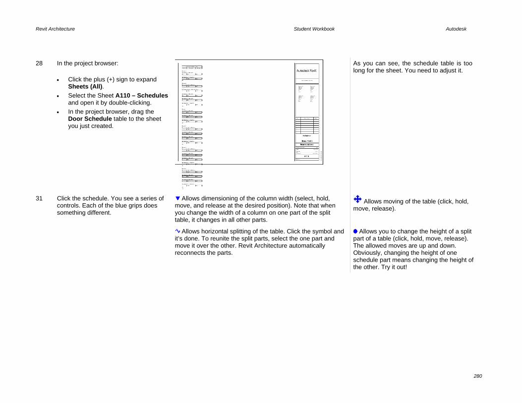
Revit Architecture Student Workbook Autodesk
280
28 In the project browser: • Click the plus (+) sign to expand
Sheets (All). • Select the Sheet A110 – Schedules
and open it by double-clicking. • In the project browser, drag the
Door Schedule table to the sheet you just created.
As you can see, the schedule table is too long for the sheet. You need to adjust it.
31 Click the schedule. You see a series of controls. Each of the blue grips does something different.
Allows dimensioning of the column width (select, hold, move, and release at the desired position). Note that when you change the width of a column on one part of the split table, it changes in all other parts.
Allows moving of the table (click, hold, move, release).
Allows horizontal splitting of the table. Click the symbol and it’s done. To reunite the split parts, select the one part and move it over the other. Revit Architecture automatically reconnects the parts.
Allows you to change the height of a split part of a table (click, hold, move, release). The allowed moves are up and down. Obviously, changing the height of one schedule part means changing the height of the other. Try it out!

Revit Architecture Student Workbook Autodesk
281
32 Click the schedule on the sheet, and use the small symbols to split the schedule table,
33 Save and close the project.

Revit Architecture Student Workbook Autodesk
282
Exercise 18B: Room Objects, Schedules and Tags In this exercise you work with the room schedule and tags. The last exercise did not address the issue of tags. To work with or create a door schedule, all you need are the doors in a project. The tags just present information already associated with the door or in the schedule. The same is true for room schedules. A room does not appear in a schedule unless you place a room object. The exercise uses the same data set as the previous exercise, but does not build on the information created in that exercise. Create a Duplicate View of the
Second Floor When creating a schedule view, you may find it useful to duplicate the plan view in question so you have one plan view free of tags and colors, or to use a different type of tag.
1 On the File menu, click Open > Browse and find the file m_Unit 18b – Start.rvt delivered with the workbook. Open the file. In the project browser, verify that Level 2 is current.
2 Duplicate Level 2 view: • Right-click the Level 2 view. Click
Duplicate View > Duplicate. • Right-click the Copy of Level 2
view. Click Rename. • Change the Name to Level 2-
Room Areas. • Click OK.
The duplicated view automatically becomes the active view.
3 In the Level 2 - Room Areas view, type VV to access the view’s graphic overrides. • Next to Visibility/Graphics
Override, click the Edit button. • In the dialog box, click the
Annotation Categories tab. • Clear Grids, Sections, and
Elevations.

Revit Architecture Student Workbook Autodesk
283
Don’t close the dialog box yet.
4 In the Visibility/Graphics dialog box, click the Model Categories tab. Under the Site category, clear Property Lines. Click OK to close each dialog box.
5 If the Room and Area design bar is not available, right-click the design bar. Click Room and Area to open the tools.
This step displays the Room and Area tools on the design bar.
6 With the same view Level 2 – Rooms active, on the Window menu, click Close Hidden Windows.
Before you start tagging your plan, split the screen so you can simultaneously view the Level 2 - Room view as well as the Door Schedule (Level 2).
7 In the project browser, activate the Door Schedule (Level 2). On the Window menu, click Tile to see both views parallel.

Revit Architecture Student Workbook Autodesk
284
8 In the plan view, zoom into the upper-left quadrant of the plan.
9 On the Room and Area design bar, click Room, and set the options bar settings as shown at right.
10 Click the center room shown here.
After you place the room, you should be able to hover your cursor over the room and see an “X” in the room. This is the room object. You should also now see the room in the door schedule under the To Room column.
11 Click Room Tag and tag (click) the room you just added.

Revit Architecture Student Workbook Autodesk
285
Note that Revit Architecture also allows modification of the names of the rooms from within the schedule table itself. For this, however, you need to have created the room schedule, something you have not yet done.
Although the room names appear in your door schedule table, you cannot modify them from here. When the room schedule is created before the actual tagging and with the condition that the room names exist in that table, you can select that room as soon as it has been inserted using the options bar.
12 Using that principle, you are now going to change the name of each room.
13 Click the Modify tool. Click the tag. Change the room name from Room to Bathroom.
14 On the Room and Area design bar, click Room. Set the parameters in the options bar as shown.
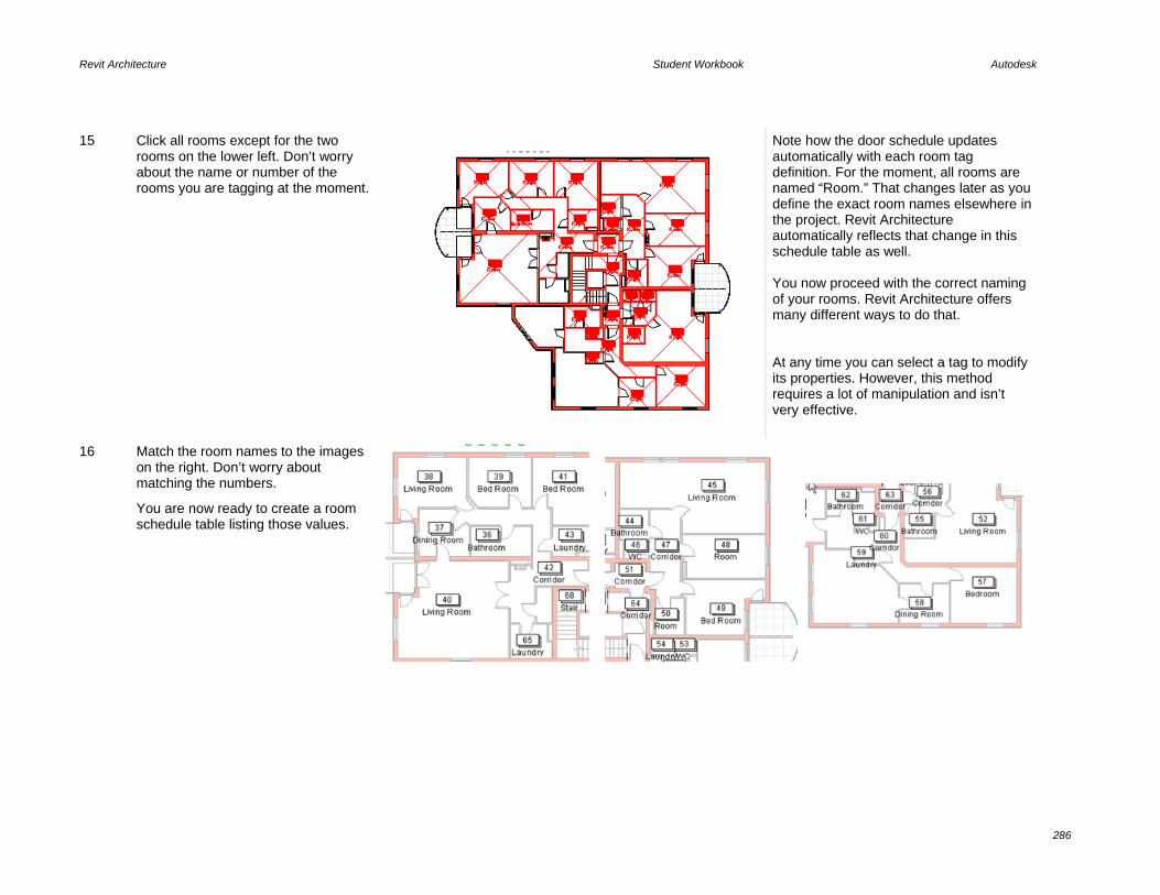
Revit Architecture Student Workbook Autodesk
286
15 Click all rooms except for the two rooms on the lower left. Don’t worry about the name or number of the rooms you are tagging at the moment.
Note how the door schedule updates automatically with each room tag definition. For the moment, all rooms are named “Room.” That changes later as you define the exact room names elsewhere in the project. Revit Architecture automatically reflects that change in this schedule table as well. You now proceed with the correct naming of your rooms. Revit Architecture offers many different ways to do that. At any time you can select a tag to modify its properties. However, this method requires a lot of manipulation and isn’t very effective.
16 Match the room names to the images on the right. Don’t worry about matching the numbers.
You are now ready to create a room schedule table listing those values.

Revit Architecture Student Workbook Autodesk
287
17 On the View tab of the design bar, click Schedule\Quantities. Select Rooms as a category. Click OK.
18 In the Schedule Properties dialog box, add the fields: • Number • Name • Area • Perimeter • Level
19
Click the Sorting/Grouping tab. Under Sort By, select Number.

Revit Architecture Student Workbook Autodesk
288
20 Click the Formatting tab. Select Level. Select the Hidden Field check box.
21 Select Area, and click Field Format. • Clear the Use Project Settings
check box. • Set Square Meters as Units, 1
Decimal Place as rounding. • Set m2 as Unit Suffix. Repeat for the Perimeter field (set units as meters, rounding one decimal place). Click OK to return to the schedule window.
Add Rooms via the Room Schedule
You can use the Add Rows button on the schedule to create rooms that are unassigned. Once you are adding rooms, these rooms are available on the options bar menu.

Revit Architecture Student Workbook Autodesk
289
22 Set the Room Schedule view current. Next to Rows, click the New button two times.
23 Type Kitchen for the name for the first row that appears at the bottom of the schedule.
24 Click in the room name cell for the second row you added. Select Living Room from the list.
If you have entered a value, you can pick it using the list in the schedule cell.
25 In the project browser, make the Level 2 – Room Areas current. On the design bar, click Room and Area. Click Room. Set the options bar settings as shown at right.
Any unassigned room is available from the room list on the options bar.

Revit Architecture Student Workbook Autodesk
290
26 Add the kitchen and living room as shown at right.
In this manner you can use the options bar to delete any room in the schedule.
If the room has not been placed in the project yet, it is simply deleted from the schedule. If the room exists as an object in the project, you receive a warning that you are deleting the room and the tag associated with it.
Separate Rooms In this section you add room separation lines to separate out the stair from the corridor area. These lines enable rooms to exist side by side when there is no wall between the rooms.
27 Find the corridor in the center of the building. Click that room number on the schedule. On the options bar, click Show. When the plan zooms to the room, close the Show Elements dialog box.
The plan zooms to this room. The function is the same as when you click the Show button on the door schedule. Note that the stair and corridor are the same space.

Revit Architecture Student Workbook Autodesk
291
28 On the Room and Area design bar click Room Separation.
29 Draw lines from wall to wall at the treads. Click Modify.
30 Click the room object to verify that it extends only to the risers at these locations.
Add a Multifloor Spanning Room
Stairs and how their areas are calculated vary from region to region. Often, stairs, atriums, or other spaces that span multiple floors are calculated only once. To do this, the room must have parameters that tell it to extend the full height of the building.
In this case, the stair extends from level 1 to level 4 with an offset above level 4 of 2030 (the height at which is hits the roof object.
31 Click the Room tool. Set the parameters in the options bar as shown.

Revit Architecture Student Workbook Autodesk
292
32 Click the area of the stair to place this room. Click the tag, and change the name from Room to Stair.
33 Open Level 3 plan view: Click the Room Tag tool. Click the same area to tag the stair room in this view.
The room object extends up through this floor level and so is found by the tag. None of the other spaces on this floor have a room object and thus cannot be tagged by the tool.
Add a Volume Column to the Room Schedule
If you turn on volume in the room and area settings, you can then add the volume column to the room schedule.
34 On the design bar, click Room and Area > Settings.

Revit Architecture Student Workbook Autodesk
293
35 Select At System Computed Height. Select the Compute Room Volumes check box.
This dialog box also gives you control over how the room areas are calculated.
36 Set the Room Schedule current, and open its view properties. Edit the fields to add Volume to the schedule.
37 Click OK to return to the schedule.
The schedule now reports volume for each of the rooms in the project.
Exercise 18C: Calculated Values for Rooms In this exercise you duplicate the schedule created in the last exercise to create another in which you directly read the total area of each room as well as the percentage of that room type according to the total area of the building. Create a Calculated Values Table
for the Second Level

Revit Architecture Student Workbook Autodesk
294
1 On the File menu, click Open > Browse and find the file m_Unit 18c – Start.rvt delivered with the workbook. Open the file. Verify that the Room Schedule is the current view.
2 In the project browser, duplicate the room schedule. Rename it Room Schedule (Level 2 – Surfaces).
3 Right-click the new schedule. Click Properties. Click the Edit button next to Fields.
4 On the Fields tab, click Calculated Value.
5 In this dialog box set the following: Next to Name, enter a name for the new field (% (Total), for example). • Click Percentage. • Next to Of, select Area. • Next to By, select Grand Total. • Click OK.

Revit Architecture Student Workbook Autodesk
295
6 Click the Sorting/Grouping tab: • Change the sorting condition to
Name. • Select Header and Footer (keep
Title, Count, and Totals). • Select Blank Line. • Select Grand Total (keep Title,
Count, and Totals).
7 Click the Formatting tab: • Select the calculated field that you
created previously (%Total). • Select Calculate Totals. • Click Field Format. • Next to Units, select Percentage,
Rounding 1 Decimal Place. • Unit suffix: none. • Click OK to close each dialog box
and return to the schedule.
8 Save the project.

Revit Architecture Student Workbook Autodesk
296
Exercise 18D: Room Schedule Keys In this exercise you add room finish keys to the schedule. To finish your schedule table, you are going to create a schedule key. The idea is to be able to associate to each room a finish for the walls, floor, and ceiling. Instead of tediously copying and pasting these values to each room, you prepare a new schedule in which all those finishes are listed and then link it to your room schedule. Add Room Finish Keys to
Schedule
1 On the File menu, click Open > Browse to find the file m_Unit 18d – Start.rvt delivered with the workbook. Open the file.
2 On the Views design bar, click Schedule/Quantities. • From the Category list, select
Rooms. • Click Schedule Keys. • You can change the name of the
schedule if you want to. • Click OK to open the Schedule
Properties dialog box.
3 On the Available Fields list, select: • Floor Finish. • Wall Finish. • Ceiling Finish. Either select each field by clicking the Add button each time, or you can select them all by holding CTRL and add them all at once.
The Key Name field is automatically generated. It is this field that creates the link between the two schedules. So, do not delete it!

Revit Architecture Student Workbook Autodesk
297
4 Click OK.
The schedule key table is usually empty when created. Your next task is to fill it with all the necessary information.
5 On the options bar, click New.
6 In principle you should now fill out all the information you have about all possible finishes. The first column is automatically generated as a numeric column in which the number increments with every added line. You can change the numbers, but you cannot duplicate numbers.
Next, you link this schedule to the room schedule so that you can use these values within it.
7 In the project browser, right-click the room schedule. Click Properties. Click the Edit button next to Fields. Under Available Fields, you can now add the following fields: • Room Style. • Floor Finish. • Wall Finish. • Ceiling Finish. Click OK to return to the room schedule.

Revit Architecture Student Workbook Autodesk
298
8 The principle is simple: you click the Room Style fields and select the key corresponding to the finishes in that room. The Floor Finish, Wall Finish, and Ceiling Finish columns are automatically filled.

Revit Architecture Student Workbook Autodesk
299
Exercise 18E: Color Scheme In this exercise you create a color fill legend to give a visual indicator to the information held in the room objects. Add a Color Scheme Legend
1 On the File menu, click Open > Browse. Find the file m_Unit 18e – Start.rvt delivered with the workbook. Open the file.
2 In the project browser, activate Level 2 -Rooms. • On the Drafting menu, click Color
Scheme Legend. • Move the cursor and click to place the
legend next to the floor plan. • In the dialog box, click Color Scheme:
Color Fill 1. • Click OK.

Revit Architecture Student Workbook Autodesk
300
3 Revit Architecture automatically fills each tagged room with the corresponding color. All rooms with the same area are given the color defined in the legend. These colors can be modified at any point, and that change is populated on the legend, as well as in the entire drawing.
4 Select the legend.
Allows redimensioning of the width of the legend. If the legend has more than one column, you can change their widths independently.
Allows you to redimension the height of the legend. Should the height you are setting not be sufficient for the entire legend, Revit Architecture automatically splits the legend into various columns.
5 On the options bar, click Edit Color Scheme.
The default color scheme for this project is set to color the rooms by area range. In principle, By Range works the same way as By Value. To modify the conditions of the color fill, fix a minimum value (default: 20m²) and click the Split button. The first condition you get is a double of the start condition. If you continue to split, the result depends on which cell was active when you clicked the

Revit Architecture Student Workbook Autodesk
301
Split tool. In any case, you can set any number as a value in the cells.
6 Change the Color value to Name. Click OK in the warning dialog box.
If the color scheme does not automatically fill in all the values, click OK and then click Edit Color Scheme again.
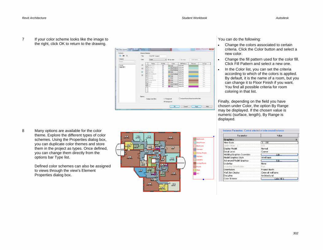
Revit Architecture Student Workbook Autodesk
302
7 If your color scheme looks like the image to the right, click OK to return to the drawing.
You can do the following: • Change the colors associated to certain
criteria. Click the Color button and select a new color.
• Change the fill pattern used for the color fill. Click Fill Pattern and select a new one.
• In the Color list, you can set the criteria according to which of the colors is applied. By default, it is the name of a room, but you can change it to Floor Finish if you want. You find all possible criteria for room coloring in that list.
Finally, depending on the field you have chosen under Color, the option By Range may be displayed. If the chosen value is numeric (surface, length), By Range is displayed.
8 Many options are available for the color theme. Explore the different types of color schemes. Using the Properties dialog box, you can duplicate color themes and store them in the project as types. Once defined, you can change them directly from the options bar Type list. Defined color schemes can also be assigned to views through the view’s Element Properties dialog box.

Revit Architecture Student Workbook Autodesk
303
9 Load the families for a bed and dresser, and place them in the lower-right bedroom.
10 In the drawing window, click the Color Fill. On the options bar, click Edit Color Scheme.
11 Next to Display Color Fill In, toggle between Foreground/Background colors. Click Apply each time. Click OK to any warnings about changing view to Wireframe or Hidden mode.
If you have assigned a material to your floor with a pattern, this setting also affects the patterns.

Revit Architecture Student Workbook Autodesk
304
Exercise 18F: Legends In this exercise you create a window legend. A legend is a chart of symbols in the project. You can create legends for any Revit Architecture object, including walls, windows, and furniture. Create a Legend
1 On the File menu, click Open > Browse and find the file m_Unit 18f – Start delivered with the workbook. Open the file.
2 On the design bar, click Views. Click Legend.
This creates and opens a new view. The new view is created in its own category in the project browser.
3 Rename the legend Window Legend.
The legend view appears blank with no views of the building model. Think of a legend as a piece of paper on which you place symbols that represent the objects in the building model.
4 Click the design bar Modeling tab. Notice that none of the tools are available. There is a special tool you use to add the objects in symbol mode to the legend.

Revit Architecture Student Workbook Autodesk
305
5 On the design bar, click Drafting. Click Legend Component.
6 Use the options bar list to select the following: • Family = M_Case Double All
Bar:1200x1350 mm. • View = Elevation Front.
The window symbol is shown in the legend.
7 Click in the legend to place the window.
8 Repeat, adding the window types shown here.

Revit Architecture Student Workbook Autodesk
306
9 Change the scale of the legend to 1:20.
10 On the Basics design bar, use the Dimension tool to dimension the windows.
Because this is a window type, the window legend is a convenient location to place common information about this window that occurs in multiple locations in the project.
11 On the Basics design bar, use the Text tool to add notes to the legend.

Revit Architecture Student Workbook Autodesk
307
12 You can place a legend on any sheet by dragging from the project browser.
13 Save and close the project.
Exercise 18G: Material Takeoffs A material takeoff is just a specialized form of a schedule. This exercise leads you through creating a material takeoff view for the walls. The exercise uses the same data set as the previous exercise but does not build on the information created in that exercise. Create a Material Takeoff List
1 On the File menu, click Open > Browse. Find the file m_Unit 18g – start delivered with the workbook. Open the file. On the View menu, click New > Material Takeoff. In the New Material Takeoff dialog box: • Under Category, click Walls. • Click OK.
2 On the Field tab, add the fields shown in the illustration at right. Click the Filter tab.
3 Leave Filter By set to None. Click the Sorting/Grouping tab.

Revit Architecture Student Workbook Autodesk
308
4 On the Sorting/Grouping tab: • Set Sort By to Material Name. • Select the Footer check box, and
set to Title, Count, and Totals. • Select Blank Line for this sort
criterion. • Clear the Itemize Every Instance
check box.
5 On the Formatting tab: • Select Material: Area. • Select the Calculate Totals check
box.
6 Click OK.
The materials schedule is now part of the project. On your own, add the cost field and add a calculated parameter that multiplies the area field times the cost field.

Unit 19 Theory: Time
Revit Architecture: Phasing This unit explains how the time parameter is managed in Revit Architecture. 1 Open file m_Unit 19 – Start.rvt.
2 In the project browser, right-click Floor Plan Level 2. Click Duplicate. Rename the new view Level 2 Demolition.
3 In the Level 2 Demolition plan, open the view properties and change:
• Phase Filter = Show All. • Phase = New Construction.
To open View Properties you can right-click the view in the project browser and then click Properties, or right-click anywhere in the view and click View Properties.

Revit Architecture Student Workbook Autodesk
310
4 Click OK to return to the drawing window.
Note how the appearance of the existing components changes when the phase of the view is changed. The first thing you should notice is that views have a parameter called phase. Depending on the value of this parameter, all components created (or demolished) in this view have their created phase set as the one the view belongs to. In this case, the walls and doors you demolish were created in the Existing phase and are demolished in the New Construction phase.
5 Click one of the walls in the plan. Open its properties. Verify that the wall’s Phase Created is set to Existing and Phase Demolished is set to None.
For every object in the building model there is also a phasing property. For each object Revit Architecture tracks the phase created and the phase demolished. As noted earlier, the phase created is read from the phase property of the view in which it is created.
Demolish Walls and Doors
6 On the toolbar, click Demolish. Click the walls in the middle of the building (see image). Also click the wall dividing the bathroom area on the bottom left (see image).
When you demolish a component, its display changes according to the phase filter assigned to the view. Phase filters are found in the view properties. The override for the display of the components is defined in the phase settings: Settings > Phases > Graphic Overrides tab.

Revit Architecture Student Workbook Autodesk
311
7 Add new walls and doors as shown in image. You don’t need to be exact about positioning the components, but you should design a plan that makes sense.
As you add the walls, verify that the height is set to Level 3.
8 In the project browser, duplicate the Level 2 Demolitions plan view. Rename it to Level 2 – Complete.
9 Open the view properties and change the Phase Filter parameter to Show Complete. Click OK to exit the dialog box.

Revit Architecture Student Workbook Autodesk
312
10 On the Room and Area design bar, click Room and create (and rename) the rooms as shown in the image. For the corridor and the top WC to the left of the kitchen: • Select the tag. • On the options bar, select Leader. • Click the drag symbol under the tag
number. • Drag tag to the desired position.
Create Schedules for the Phases
11 In the project browser, under Schedules/Quantities, right-click the Schedule table: Room Schedule – Existing. Click Duplicate. Rename it Room Schedule – New Construction.
12 In the project browser, right-click the new schedule. Click Properties.
13 Change the Phase parameter to New Construction. Click OK.
The schedule filters to the rooms created in the new construction.

Revit Architecture Student Workbook Autodesk
313
14 In the project browser duplicate the 3D view: 3D Cutout – Existing. Rename the new view 3D Cutout – Demolitions. Open the new 3D View properties and change the Phase to New Construction. Click OK.
15 Duplicate this 3D view, and name the new view: 3D Cutout – Complete. Open the new view’s properties. Change the Phase Filter to Show Complete. Click OK.
16 Open the Sheet view: A100 - Commercial – Residential. Drag the view: Level 2 Demolition on the sheet and position it in the middle, as shown in image.
This sheet already has the original views placed on the sheet: • 3D Existing Cropped. • Existing Room Schedule. • Level 2 (Floor Plan).

Revit Architecture Student Workbook Autodesk
314
17 Drag onto the sheet the following views: • Level 2 – Complete. • 3D Cutout – Demolitions. • 3D Cutout – Complete. • Room Schedule – New
Construction. Position them as shown in image. Make sure that all the plans are set to 1:100 scale and the 3D models are set to 1:200 scale.
The sheet is complete
Save your file if you want to keep it for reference. This data set looks like the data set for Unit 20. However the file m_Unit 20 – Start .rvt has added Design Options in place that are used in the exercise steps.

Unit 20 Theory: Variation
Revit Architecture: Options This unit guides you through the powerful Design Options feature. You start using a file that already contains a couple of design options. Review Design Options
1 Open file m_Unit 20 – Start. This file contains an option set with two different design options. Open Floor Plan views: Op 1 – Level 2 and Op 2 – Level 2 Tile windows to display both options.
Note how tiling windows lets you visualize both, or more, options in different views. Both views represent the second floor of the building. All components are held in the building model. However, the interior walls of the floor, along with the stair and east wall, are held in Design Options.
2 In Plan: Level 2 – Option 1, try to click the door of Offices 26 (middle top).
When the project contains Design Options, the options bar displays a check box to allow selection of components that are part of the option set:
This is just a check to keep you from inadvertently changing objects that are in a Design Option.
View the Options
3 Right-click the toolbar. Verify that the Design Options toolbar is selected.
In this file you have only one option set, but you can have as many as you want. Normally, an option set is a specific part of a building where you want to try different design alternatives. An option set can contain as many options as you want.

Revit Architecture Student Workbook Autodesk
316
4 Click the Design Options tool to open the Design Options dialog box.
5 Select Option Set 1 – Standard (Primary). Click Edit Selected. Do not close the Design Options dialog box yet.
The Now Editing window displays the active, edited option.
When you edit an option, all components that are not part of the option are dimmed.
With two options as in this case, you have three sets of objects: Those in the main model. Those in sets unique to each of the options. When you are editing an option, you can see and refer to objects in the main model, but by default you cannot edit them.
6 In Design Options dialog box: • Click Finish Editing. • Click Curtain Wall. • Click Edit Selected. • • • Click Close.
The options bar displays a check box that allows selection of components that belong to the main model (not to an option set).
7 Click Edit Option to end editing of the curtain wall option.
You return to standard Edit mode with neither option open.
Copy Elements Between Options You can copy and paste elements from one Design Option to another.

Revit Architecture Student Workbook Autodesk
317
8 Click Edit Option, and on the list, select Options Set 1: Standard (Primary).
This shortcut bypasses the Design Options dialog box. This tool is cyclical. If you click it again, you exit Edit mode (don’t do this yet).
9 While editing the Standard Option, select the stairway on the east end of the building. On the Edit menu, click Copy to Clipboard.
Copy to Clipboard and Paste Aligned (Same Place) constitute an easy way to replicate a situation among different options. You can also duplicate an option within an option set by selecting it in the Design Options dialog box and clicking Duplicate.
10 On the Design Options toolbar, click Edit Option to finish editing the option.
The Design Options toolbar allows for quick selection of the available Design Options.
11 Click Edit Option again. From the list selectOption Set 1: Curtain Wall.
12 On the Edit menu, click Paste Aligned > Current View.
The stair now is part of this option.

Revit Architecture Student Workbook Autodesk
318
13 In the Level 2 Option 2 window, select the stair. On the options bar, click Edit.
When editing stairs, you enter Sketch mode.
14 Delete the boundary on the right edge of the landing.
15 Click the boundary tool on the design bar. On the options bar: • Click Draw. • Set the template to the Arc tool. • Redraw the landing boundary with the
arc by clicking the endpoint of the lines on either side of the staircase until you see the desired arc.
• Click Finish Sketch.
16 Add walls and doors to complete the design, as shown in image.

Revit Architecture Student Workbook Autodesk
319
17 On the Basics design bar, click Room. Click in all the empty rooms in the option. After placing the tags, rename the rooms as shown in image. Make sure you are still editing the option before adding the rooms if you want the rooms to be part of the option.
18 On the Design Option toolbar, click Edit Option to finish editing the option.
The two plan options are now complete.
Assign an Option to a View You have been working in two views that are both views of the second level.
The only difference between these is a setting in the view properties assigning one option or the other.
19 Open 3D View 1. By default, a view shows the option marked primary, in this case the standard option.
20 In the project browser, right-click the 3D view 1. Click Duplicate View > Duplicate. Rename Copy of 3D View 1 3D View - Option 2.

Revit Architecture Student Workbook Autodesk
320
21 Open the View Properties dialog box by right-clicking the view in the project browser. Click Properties. On the Visibility/Graphics Overrides line, click the Edit button.
When there are Design Options in the project file, Revit Architecture adds a new tab in the visibility settings of the views. You can display any option in any desired view: plans, elevations, sections, and so forth.
22 On the Design Options tab, select Curtain Wall from the list under the Design Options column.
The list displays the available options for the option set. When the value is set to Automatic, the view displays the primary option but switches to show the one you are modifying when in Edit mode.
23 Click OK to close each dialog box and see the changes.
Assign an Option to a Schedule
24 Create a duplicate schedule for the option: • In the project browser, go to the
Schedules/Quantities category and right-click Room Schedule – Standard Option > Duplicate View > Duplicate.
• Rename the new schedule view Room Schedule - Curtain Wall Option.
Schedules are views as plans and sections. They can display the desired design option to evaluate the different quantities or costs according to the option displayed.

Revit Architecture Student Workbook Autodesk
321
25 Assign the option to the new schedule view: • Right-click the Room Schedule – Curtain
Wall Option again. Click Properties. • Click the Visibility/Graphics Overrides
Edit button. • From the list under the Design Options
column, select Curtain Wall. • Click OK.
Although access to this parameter is a bit different for the schedule than for the 3D view, the theory is the same. A schedule is just a text view of the building model.
You now have two different room schedules. The rooms unique to each option are listed along with those that are common to both options such as the meeting room, WC, and Service.
Place Views of the Options on a Sheet
26 In the project browser, double-click the sheet A101 – Options Compared.
27 In the project browser, drag Floor Plan: Op 2 Level 2 onto the sheet as shown in the image. Place the following views on the sheet, as shown in image: • 3D view Option 2. • Door Schedule Curtain Wall Option. • Room Schedule – Curtain Wall Option.
You have to turn on the crop region of the 3D view Option 2 and adjust the boundaries of the crop region to fit on the sheet.

Revit Architecture Student Workbook Autodesk
322
Optional Exercise: Change Primary Option and Accept Primary
When you've made a decision about the option and are ready to continue with the project without design options, you set the Design Option you want to keep as the primary design option and then accept it.
This deletes any items you have in the nonprimary option and deletes any views set to the nonprimary option.
Because the following steps delete the nonprimary elements and views, save your project now if you want to keep your progress to this point.
28 Open Floor Plan Level 2 – Main Model.
29 On the Design Options toolbar, click Design Options.
30 Select the Curtain Wall option. Click Make Primary.
A warning may appear when accepting the primary option, depending on how walls are joined. You can normally ignore these warnings and proceed with the next step.
31 Select Option Set 1. Click Accept Primary.

Revit Architecture Student Workbook Autodesk
323
32 Click Yes when the dialog box opens. Because you are finished with the options process, accepting the primary option deletes all the elements that are stored in Option Set 1: Standard option.
33 Click Delete in the dialog box.
Because you are deleting all the objects that are shown in these views, deleting the views makes sense. The other views, such as 3D View 1, as well as the schedules, are set to display, which automatically displays the primary option. These views are not deleted when you accept the primary option.
34 The Design Options dialog box is now empty.
After you click the Accept Primary button, all options disappear and the components in the primary option become part of the main model. Note that the sheet now displays the same information twice and the views display the same model.
Autodesk, AutoCAD, DWG, Revit, and 3ds Max are registered trademarks or trademarks of Autodesk, Inc., in the USA and/or other countries. All other brand names, product names, or trademarks belong to their respective holders. Autodesk reserves the right to alter product offerings and specifications at any time without notice, and is not responsible for typographical or graphical errors that may appear in this document. © 2007 Autodesk, Inc. All rights reserved.