R507 Rewrite with technical changes - NADRA
30
1 R507 Rewrite with technical changes Created 10-30-2015 Page R403.1.4.1 Frost protection 2 R507.1 Decks 3 R507.2 Materials 5 R507.3 Footings 9 R507.4 Deck posts 11 R507.5 Beams 13 R5.7.6 Joists 17 R507.7 Decking 20 R805.8 Guards 21 R507.9 Lateral and vertical supports 23
Transcript of R507 Rewrite with technical changes - NADRA

1
R507 Rewrite with technical changes
Created 10-30-2015
Page
R403.1.4.1 Frost protection 2
R507.1 Decks 3
R507.2 Materials 5
R507.3 Footings 9
R507.4 Deck posts 11
R507.5 Beams 13
R5.7.6 Joists 17
R507.7 Decking 20
R805.8 Guards 21
R507.9 Lateral and vertical supports 23

2
R403.1.4.1 Frost protection. Except where otherwise protected from
frost, foundation walls, piers and other permanent supports of
buildings and structures shall be protected from frost by one or more
of the following methods:
1. Extended below the frost line specified in Table R301.2.(1);
2. Constructing in accordance with Section R403.3;
3. Constructing in accordance with ASCE 32; or
4. Erected on solid rock.
Exceptions:
1. Protection of freestanding accessory structures with an area of
600 square feet (56 m2) or less, of light-frame construction,
with an eave height of 10 feet (3048 mm) or less shall not be
required.
2. Protection of freestanding accessory structures with an area of
400 square feet (37 m2) or less, of other than light-frame
construction, with an eave height of 10 feet (3048 mm) or less
shall not be required.
Footings shall not bear on frozen soil unless the frozen condition is
permanent.

3
SECTION R507
EXTERIOR LIGHT-FRAMED DECKS
R507.1 Decks. Light-framed decks shall be either freestanding or attached to a
primary structure. Light framed decks shall be constructed in accordance with this
section, or designed in accordance with Section R301 for materials and conditions
not prescribed herein. Light-framed decks shall be constructed to provide a
complete load path to transfer both vertical and lateral loads to their foundations or
through attachment to a primary structure. Where joists or beams are cantilevered,
the supporting framing shall be designed to resist uplift resulting from the full live
load specified in Table R301.5 acting on the cantilevered portion of the deck.
R507.1.1 Freestanding decks. Freestanding decks shall be supported by at
least two parallel rows of beams and shall be limited in height by the post
size specified in Table R507.4. The lateral load resistance shall be permitted
to be provided by diagonal braces in both directions in accordance with
Figure R507.1.1, or by other methods in accordance with accepted
engineering practice.
Exception: Freestanding wood patios consisting of joists directly
supported on grade over their entire length, need only comply with
Sections R507.3, R507.4, and Chapter 3
R507.1.2 Decks attached to a primary structure. Decks which are not
freestanding shall be supported by a ledger board connection to the band joist
of the primary structure. Decks shall be constructed to provide a complete
load path for both vertical and lateral loads in accordance with Section
R507.9. Such attachment shall not be accomplished by the use of toenails or
nails subject to withdrawal. Where connections to the supporting structure, as
required in Section R507.9, cannot be verified, decks shall be freestanding in
accordance with Section R507.1.1.

4
FIGURE R507.1.1
FREESTANDING DECKS
5
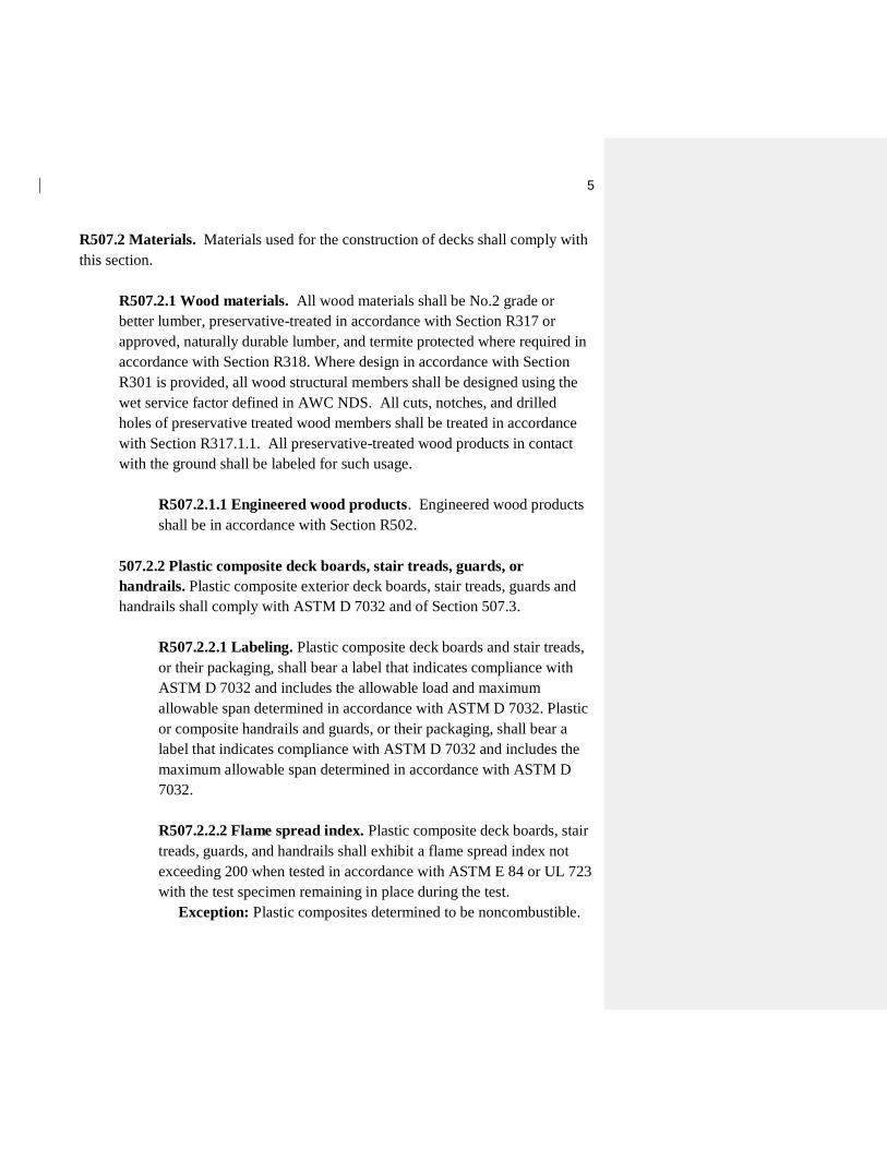
R507.2 Materials. Materials used for the construction of decks shall comply with
this section.
R507.2.1 Wood materials. All wood materials shall be No.2 grade or
better lumber, preservative-treated in accordance with Section R317 or
approved, naturally durable lumber, and termite protected where required in
accordance with Section R318. Where design in accordance with Section
R301 is provided, all wood structural members shall be designed using the
wet service factor defined in AWC NDS. All cuts, notches, and drilled
holes of preservative treated wood members shall be treated in accordance
with Section R317.1.1. All preservative-treated wood products in contact
with the ground shall be labeled for such usage.
R507.2.1.1 Engineered wood products. Engineered wood products
shall be in accordance with Section R502.
507.2.2 Plastic composite deck boards, stair treads, guards, or
handrails. Plastic composite exterior deck boards, stair treads, guards and
handrails shall comply with ASTM D 7032 and of Section 507.3.
R507.2.2.1 Labeling. Plastic composite deck boards and stair treads,
or their packaging, shall bear a label that indicates compliance with
ASTM D 7032 and includes the allowable load and maximum
allowable span determined in accordance with ASTM D 7032. Plastic
or composite handrails and guards, or their packaging, shall bear a
label that indicates compliance with ASTM D 7032 and includes the
maximum allowable span determined in accordance with ASTM D
7032.
R507.2.2.2 Flame spread index. Plastic composite deck boards, stair
treads, guards, and handrails shall exhibit a flame spread index not
exceeding 200 when tested in accordance with ASTM E 84 or UL 723
with the test specimen remaining in place during the test.
Exception: Plastic composites determined to be noncombustible.

6
R507.2.2.3 Decay resistance. Plastic composite deck boards, stair
treads, guards and handrails containing wood, cellulosic or other
biodegradable materials shall be decay resistant in accordance with
ASTM D 7032.
R507.2.2.4 Termite resistance. Where required by Section 318,
plastic composite deck boards, stair treads, guards and handrails
containing wood, cellulosic or other biodegradable materials shall be
termite resistant in accordance with ASTM D 7032.
R507.2.2.5 Installation of plastic composites. Plastic composite
deck boards, stair treads, guards and handrails shall be installed in
accordance with this code and the manufacturer’s instructions.
R507.2.3 Fasteners and connectors. Metal fasteners and connectors used
for all decks shall be in accordance with Section R317.3 and Table
R507.2.3.
R507.2.4 Flashing: Flashing shall be corrosion-resistant metal of
minimum nominal 0.019 – inch thickness or approved non-metallic material
that is compatible with the substrate of the structure and the decking
materials.
R507.2.5 Alternative materials. Alternative materials, including glass and
metals, designed in in accordance with accepted engineering practice shall
be permitted subject to the approval of the building official.

7
BASIC FASTENER REQUIREMENTS ALTERNATE MATERIALS, COATINGS,
AND FINISHES ITEM MATERIAL MINIMUM
FINISH/COATING
Nails and
timber rivets
In accordance with
ASTM F1667
Hot-dipped galvanized
per
ASTM A 153
300 Series
stainless steel;
silicon bronze,
or copper
Bolts c and lag
screws d
(including nuts
and washers)
In accordance with
ASTM A 307
Hot-dipped galvanized
per
ASTM A153 Class C
(Class D for 3/8”
diameter and less) or
Mechanically
galvanized per
ASTM B 695, Class 55
or 410 stainless steel
300 Series
stainless steel;
silicon bronze,
or copper
Metal
connectors
Per manufacturer’s
specification
ASTM A 653 type G185
zinc coated galvanized
steel or
Hot-dipped galvanized
per
ASTM A 123 providing
a minimum average
coating weight of 2.0
oz./ft2 (total both
sides)
300 Series
stainless steel
TABLE R507.2.3
FASTENER AND CONNECTOR SPECIFICATIONS FOR DECKS a, b, e

8
a. Alternative materials, coatings and finishes shall be subject to approval
by the building official provided equivalent performance is demonstrated
by the manufacturer of the fastener or connector.
b. Fasteners and connectors exposed to salt water or located within 300 feet
of a salt water shoreline shall be stainless steel, Type 304, 305, or 316.
c. Holes for bolts shall be drilled a minimum 1/32” and a maximum 1/16”
larger than the bolt.
d. Lag screws ½” and larger shall be predrilled to avoid wood splitting per
National Design Specification (NDS) for Wood Construction with 2005
Supplement.
e. Stainless steel driven fasteners shall be in accordance with ASTM F
1667.

9
R507.3 Footings. Decks shall be supported on solid concrete footings or other
approved structural systems of sufficient size to accommodate all loads according
to Section R301 and to transmit the resulting loads to the soil within the limitations
as determined from the character of the soil.
Exception:
1. Freestanding wood patios where the joists are supported directly on grade
over their entire length.
2. Precast concrete deck blocks for freestanding decks may be placed on grade
provided all of the following deck criteria are met:
a. The area of the deck does not exceed 200 square feet (18.9 m2),
b. The walking surface is not more than 20 inches (616 mm) above grade
at any point within 36 inches (914 mm) measured horizontally from
the edge,
c. The joists bear directly on precast concrete deck blocks without
support by beams or posts, and their span lengths comply with Table
R507.6.
R507.3.1 Minimum size. The minimum sizes of concrete footings shall be
in accordance with Table R507.3.1, based on the tributary area and
allowable soil bearing pressure in accordance with Table R401.4.1.
R507.3.2 Minimum depth. Deck footings shall extend below the frost line
specified in Table R301.2(1).

10
TABLE R507.3.1
MINIMUM FOOTING SIZE FOR DECKS
a. Interpolation permitted, extrapolation not permitted
b. Based on highest load case: Dead + Live or Dead + Snow
c. Assumes minimum square footing to be 12” x 12” x 6” and a 6x6
post. If the support is a brick/cmu pier, the minimum side of a square
footing shall be equal to the size of the pier plus two 2” projections
(4” total projection).

11
R507.4 Deck posts. For single-level wood-framed decks with beams sized in
accordance with Table R507.5 deck post size shall be in accordance with Table
R507.4.
TABLE R507.4
MAXIMUM DECK POST HEIGHT a
DECK POST SIZE
HEIGHT FOR DECKS
ATTACHED TO
PRIMARY
STRUCTURE
HEIGHT FOR
FREESTANDING
DECKS
4 x 4 8'
4 x 6 8'
6 x 6 14'
8 x 8
For SI: 1 foot = 304.8 mm.
a. Measured to the underside of the beam.
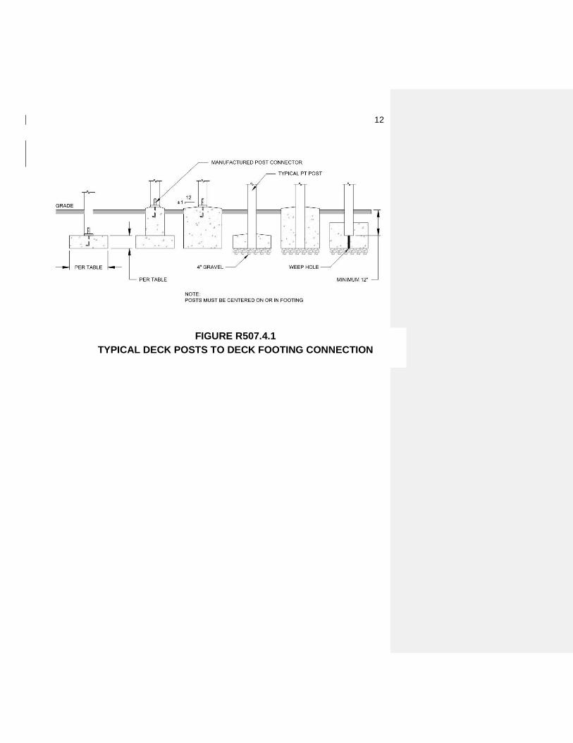
R507.4.1 Deck post to deck footing connection. Where posts bear on
concrete footings in accordance with Section R403 and Figure R507.4.1,
posts shall be restrained to prevent lateral displacement at the bottom
support. Such lateral restraint shall be provided by manufactured connectors
installed in accordance with the manufacturers’ instructions or embedded in
concrete piers or other approved footing system.
12
FIGURE R507.4.1
TYPICAL DECK POSTS TO DECK FOOTING CONNECTION

13
R507.5 Deck Beams. Maximum allowable spans for wood deck beams, as shown
in Figure R507.5, shall be in accordance with Table R507.5. Beam plies shall be
fastened with two rows of 10d (3-inch x 0.128-inch) nails minimum at 16 inches
(406 mm) on center along each edge. Beams shall be permitted to cantilever at each
end up to one-fourth of the adjacent beam span.
R507.5.1 Deck beam bearing. The ends of each beam shall have not less
than 11/2 inches (38mm) of bearing on wood or metal and not less than 3
inches (76 mm) on concrete or masonry over the entire width of the beam.
Where multi-span beams bear on intermediate posts, each ply must have full
bearing on the post in accordance with Figure R507.5.1(1) and R507.5.1(2).
R507.5.2 Deck beam to deck post connection. Deck beams shall be
attached to wood deck posts in a manner capable of resisting vertical and
horizontal applied loads. Connections shall be accordance with Figures
R507.7.1 (1) and R507.7.1 (2). Manufactured post-to-beam connectors shall
be sized for the appropriate post and beam sizes. All bolts shall have washers
under the head and nut.
Deck beams shall be attached to concrete or masonry piers in a manner
capable of resisting lateral displacement, roll over or uplift .
Other attachment methods shall be subject to approval by the building
official.
Exception: Where deck beams bear directly on footings in accordance
with Section R507.4.1.
What does this exception mean??? Currently R507.7.1 exception!!!!

14
FIGURE R507.5
TYPICAL DECK BEAM SPANS

15
For SI: 1 inch = 25.4 mm, 1 foot = 304.8 mm, 1 pound per square foot = 0.0479 kPa, 1 pound = 0.454 kg.
a. Ground snow load, live load = 40 psf, dead load = 10 psf, L/∆ = 360 at main span, L/∆ = 180 at
cantilever with a 220-pound point load applied at the end.
b. Beams supporting deck joists from one side only.
c. No. 2 grade, wet service factor.
d. Beam depth shall be greater than or equal to depth of joists with a flush beam condition.
e. Includes incising factor.
f. Northern species. Incising factor not included.
g. Beam cantilevers are limited to adjacent beam span divided by 4.
SPECIES c SIZE d
DECK JOIST SPAN LESS THAN OR EQUAL TO: (feet)
6 8 10 12 14 16 18
1- 2x6 2- 1
1- 2x8
1- 2x10
1- 2x12
2 – 2 6 6-11 5-11 5-4 4-10 4-6 4-3 4-0
2 – 2 8 8-9 7-7 6-9 6-2 5-9 5-4 5-0
2 – 2 10 10-4 9-0 8-0 7-4 6-9 6-4 6-0
2 – 2 12 12-2 10-7 9-5 8-7 8-0 7-6 7-0
3 – 2 6 8-2 7-5 6-8 6-1 5-8 5-3 5-0
3 – 2 8 10-10 9-6 8-6 7-9 7-2 6-8 6-4
3 – 2 10 13-0 11-3 10-0 9-2 8-6 7-11 7-6
3 – 2 12 15-3 13-3 11-10 10-9 10-0 9-4 8-10
Douglas fir-larch e,
Hem-fir e,
Spruce-pine-fir e, Redwood, Western cedars,
Ponderosa pine f,
Red pine f
3 6 or 2 – 2 x 6 5-5 4-8 4-2 3-10 3-6 3-1 2-9
3 8 or 2 – 2 8 6-10 5-11 5-4 4-10 4-6 4-1 3-8
3 10 or 2 – 2 10 8-4 7-3 6-6 5-11 5-6 5-1 4-8
3 12 or 2 – 2 12 9-8 8-5 7-6 6-10 6-4 5-11 5-7
4 6 6-5 5-6 4-11 4-6 4-2 3-11 3-8
4 8 8-5 7-3 6-6 5-11 5-6 5-2 4-10
4 10 9-11 8-7 7-8 7-0 6-6 6-1 5-8
4 12 11-5 9-11 8-10 8-1 7-6 7-0 6-7
3 – 2 6 7-4 6-8 6-0 5-6 5-1 4-9 4-6
3 – 2 8 9-8 8-6 7-7 6-11 6-5 6-0 5-8
3 – 2 10 12-0 10-5 9-4 8-6 7-10 7-4 6-11
3 – 2 12 13-11 12-1 10-9 9-10 9-1 8-6 8-1
TABLE R507.5
DECK BEAM SPAN LENGTHS a,b,g (ft-in)

16
FIGURE R507.5.1(1)
TYPICAL DECK BEAM TO DECK POST CONNECTION
FIGURE R507.5.1 (2)
NOTCHED POST-TO-BEAM CONNECTION
Formatted: Font: (Default) Arial, 14 pt
Formatted: Font: (Default) Arial, 14 pt
17
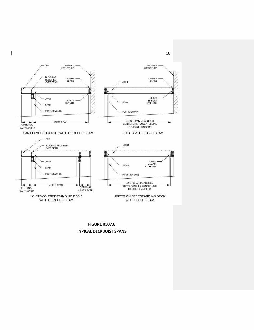
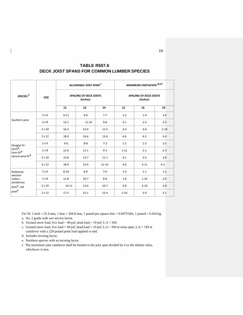
R507.6 Deck joists. Maximum allowable spans for wood deck joists, as shown in
Figure R507.6, shall be in accordance with Table R507.6. The maximum joist
spacing shall be limited by the decking material in accordance with Figure R507.7.
The maximum joist cantilever shall be limited to the actual joist span divided by 4
or the maximum cantilever length specified in Table R507.5, whichever is less.
R507.6.1 Deck joist bearing. The ends of each joist shall have not less than
11/2 inches (38mm) of bearing on wood beams or ledger boards and not less
than 3 inches (76 mm) on concrete or masonry piers over its entire bearing
width.
Joists bearing on a beam or ledger shall be connected to the beam or ledger
with (3) 10d common nails with two toenails on one side and one toenails on
the opposing side. Joist framing into the side of a ledger board or beam shall
be supported by approved joist hangers. Joists bearing on a beam shall be
connected to the beam to resist lateral displacement.
R507.6.2 Deck joist supports. Joist ends and bearing locations shall be
provided with lateral restraint to prevent rotation. Where lateral restraint is
provided by joist hangers or blocking between joists, their depth shall equal
not less than 60 percent of the joist depth. Where lateral restraint is
provided by rim joists, they shall be secured to the end of each joist with not
less than (3) 10d (3-inch x 0.128-inch) nails or (3) No. 10 x 3-inch (76 mm)
long wood screws.
18
FIGURE R507.6
TYPICAL DECK JOIST SPANS
19
For SI: 1 inch = 25.4 mm, 1 foot = 304.8 mm, 1 pound per square foot = 0.0479 kPa, 1 pound = 0.454 kg.
a. No. 2 grade with wet service factor.
b. Ground snow load, live load = 40 psf, dead load = 10 psf, L/∆ = 360.
c. Ground snow load, live load = 40 psf, dead load = 10 psf, L/∆ = 360 at main span, L/∆ = 180 at
cantilever with a 220-pound point load applied to end.
d. Includes incising factor.
e. Northern species with no incising factor
f. The maximum joist cantilever shall be limited to the joist span divided by 4 or the tabular value,
whichever is less.
SPECIES b
SIZE
ALLOWABLE JOIST SPAN c MAXIMUM CANTILEVER d,e,f
SPACING OF DECK JOISTS (inches)
SPACING OF DECK JOISTS (inches)
12 16 24 12 16 24
Southern pine
2 x 6 9-11 9-0 7-7 1-3 1-4 1-6
2 x 8 13-1 11-10 9-8 2-1 2-3 2-5
2 x 10 16-2 14-0 11-5 3-4 3-6 2-10
2 x 12 18-0 16-6 13-6 4-6 4-2 3-4
Douglas fir-larchd, hem-fird spruce-pine-fird
2 x 6 9-6 8-8 7-2 1-2 1-3 1-5
2 x 8 12-6 11-1 9-1 1-11 2-1 2-3
2 x 10 15-8 13-7 11-1 3-1 3-5 2-9
2 x 12 18-0 15-9 12-10 4-6 3-11 3-3
Redwood, western cedars, ponderosa
pinee, red
pinee
2 x 6 8-10 8-0 7-0 1-0 1-1 1-2
2 x 8 11-8 10-7 8-8 1-8 1-10 2-0
2 x 10 14-11 13-0 10-7 2-8 2-10 2-8
2 x 12 17-5 15-1 12-4 3-10 3-9 3-1
TABLE R507.6
DECK JOIST SPANS FOR COMMON LUMBER SPECIES

20
R507.7 Decking. Maximum allowable spans for decking shall be in accordance
with Table R507.7. Wood decking shall be attached to each supporting member
with not less than (2) 8d threaded nails or (2) No. 8 wood screws. For custom
decking, fasteners to joists shall be in accordance with manufacturer’s installation
requirements and subject to the approval of the building official.
TABLE R507.7
MAXIMUM JOIST SPACING
For SI: 1 inch = 25.4 mm, 1 foot = 304.8 mm, 1 degree = 0.01745 rad.
a. Maximum angle of 45 degrees from perpendicular for wood deck boards
MAXIMUM SPAN FOR DECKING
MATERIAL TYPE
AND NOMINAL SIZE
DECKING RUNNING
PERPENDICULAR TO
JOIST
DECKING RUNNING
DIAGONALLY TO
JOIST a
1¼ -inch thick wood 16 inches o.c. 12 inches o.c.
2-inch-thick wood 24 inches o.c. 16 inches o.c.
Plastic composite In accordance with
Section R507.2.2.5
In accordance with
Section R507.2.2.5

21
R507.8 Exterior Guards. Guards shall comply with Section R312.1
R507.8.1 Guard attachment. Guards shall transfer the prescribed loads to
the structure.
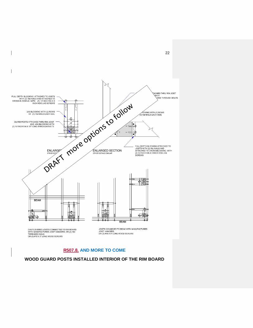
R507.8.1.1 Wood guard posts. Where guards rely on wood posts
attached to the deck frame for support, this section shall apply. Wood
guard posts shall be permitted to be located interior or exterior of the
deck framing. Wood guard post attachment shall be permitted to be
constructed in accordance with Figure R507.9.1.1. Other wood post
attachment details constructed to meet the requirements of Table
R301.5 shall be subject to approval by the building official.
R507.8.1.2 Guard posts of other materials. Where guards rely on
posts of other materials attached to the deck frame for support, this
section shall apply. Guard posts of other materials shall be permitted
to be constructed interior or exterior of the deck framing or mounted
on top of the deck framing. Guard posts of other materials shall be
permitted to be installed interior or exterior of the deck framing in
accordance with Figure R507.9.1.2 (1). Guards of other materials
shall be permitted to be installed on top of the deck framing in
accordance with Figure R507.9.1.2 (2). Other post attachment details
constructed to meet the requirements of Table R301.5 shall be subject
to approval by the building official.
R507.8.3.3 Other Guard Supports. Guards constructed without
posts shall be permitted to be attached to the deck when the guard
details are designed to meet the requirements of Table R301.5 and are
approved by the building official.
22
R507.8. AND MORE TO COME
WOOD GUARD POSTS INSTALLED INTERIOR OF THE RIM BOARD

23
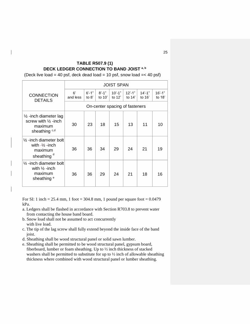
R507.9 Deck ledger connection to band joist. Deck ledger connections to band
joists shall be in accordance with this section, Tables R507.9(1) and R507.9(2),
and Figures R507.9.1(1) andR507.9.1(2). For other grades, species, connection
details and loading conditions, deck ledger connections shall be designed in
accordance with Section R301.
R507.9.1 Ledger details. Deck ledgers installed in accordance with Section
R507.9 shall be a minimum 2-inch by 8-inch nominal, pressure-preservative-
treated southern pine, incised pressure-preservative-treated Hem-fir, or
approved, naturally durable, No.2 grade or better lumber. Deck ledgers
installed in accordance with Section R507.9 shall not support concentrated
loads from beams or girders. Deck ledgers shall not be supported on stone
of masonry veneer.
R507.9.2 Band joist supporting a ledger. Band joists supporting a ledger
in accordance with Section R507.9 shall be a minimum 2-inch nominal,
solid-sawn, spruce-pine-fir lumber or better or a minimum 1-inch by 9 ½-
inch dimensional, Douglas fir, laminated veneer or better lumber. Band
joists shall bear fully on the primary structure capable of supporting all
required loads. Other framing configurations supporting a ledger
constructed to meet the load requirements of Section R301.5 shall be
subject to approval by the building official.
R507.9.3 Ledger to band joist fastener details. Fasteners used in deck
ledger connections in accordance with Table R507.9(1) shall be hot-dipped
galvanized or stainless steel and shall be installed in accordance with Table
R507.9.(2) and Figures R507.9.(1) and R507.9.(2).
R507.9.4 Deck lateral load resistance. Resistance to lateral loads required
by Section R507.1 shall be permitted to be in accordance with Figure
R507.9.4(1) or R507.9.4(2). Where the lateral load connection is provided
in accordance with Figure R507.9.3(1), hold-down tension devices shall be
installed in not less than two locations per deck, within 24-inches of each
end of the deck. Each device shall have an allowable stress design capacity
of not less than 1,500 pounds. Where the lateral load connections are
provided in accordance with Figure R507.9.3(2), the hold-down tension

24
devices shall be installed in not less than four locations per deck, and each
device shall have an allowable stress design capacity of not less than 750
pounds.
25
For SI: 1 inch = 25.4 mm, 1 foot = 304.8 mm, 1 pound per square foot = 0.0479
kPa.
a. Ledgers shall be flashed in accordance with Section R703.8 to prevent water
from contacting the house band board.
b. Snow load shall not be assumed to act concurrently
with live load.
c. The tip of the lag screw shall fully extend beyond the inside face of the band
joist.
d. Sheathing shall be wood structural panel or solid sawn lumber.
e. Sheathing shall be permitted to be wood structural panel, gypsum board,
fiberboard, lumber or foam sheathing. Up to ½ inch thickness of stacked
washers shall be permitted to substitute for up to ½ inch of allowable sheathing
thickness where combined with wood structural panel or lumber sheathing.
CONNECTION
DETAILS
JOIST SPAN
6’ and less
6’-1” to 8’
8’-1” to 10’
10’-1” to 12’
12’-1” to 14’
14’-1” to 16’
16’-1” to 18’
On-center spacing of fasteners
½ -inch diameter lag screw with ½ -inch
maximum sheathing c,d
30
23
18
15
13
11
10
½ -inch diameter bolt with ½ -inch
maximum
sheathing d
36
36
34
29
24
21
19
½ -inch diameter bolt
with ½ -inch maximum
sheathing e
36
36
29
24
21
18
16
TABLE R507.9 (1)
DECK LEDGER CONNECTION TO BAND JOIST a, b
(Deck live load = 40 psf, deck dead load = 10 psf, snow load =< 40 psf)

26
TABLE R507.9 (2) PLACEMENT OF LAG SCREWS AND BOLTS IN DECK LEDGERS AND
BAND JOISTS
For SI: 1 inch = 25.4 mm.
a. Lag screws or bolts shall be staggered from the top to the bottom along the
horizontal run of the deck ledger in accordance with Figure R507.9 (1).
b. Maximum 5 inches.
c. For engineered rim joists, the manufacturer’s recommendations shall govern.
d. The minimum distance from bottom row of lag screws or bolts to the top edge of
the ledger shall be in accordance with Figure R507.9 (1).
MINIMUM END AND EDGE DISTANCES AND SPACING BETWEEN ROWS
TOP EDGE BOTTOM
EDGE ENDS
ROW
SPACING
Ledger a 2 inches d ¾ inch 2 inches b 1 5/8 inches b
Band Joist c ¾ inch 2 inches 2 inches b 1 5/8 inches b

27
*DISTANCE SHALL BE PERMITTED BE REDUCED TO 4.5" IF LAG ARE USED OR BOLT SPACING REDUCED TO THAT OF LAG
TO ATTACH 2 X 8 LEDGERS TO 2 X
BAND LEDGER
5.5" MIN. FOR 2 X
6.5" MIN. FOR 2 X
3/4"
STAGGER IN 2
2"
LAG SCREW OR
5"
FIGURE R507.9 (1)
PLACEMENT OF LAG SCREWS AND BOLTS IN LEDGERS
For SI: 1 inch = 25.4 mm.

28
2″ MIN.
2″ MIN.
1-5/8″ MIN.
5″ MAX.
DECK JOIST
LAG SCREWS OR BOLTS
FLOOR FRAMING
EXISTING FOUNDATION WALL
JOIST HANGER
EXTERIOR SHEATHING
EXTERIOR STUD WALL
2x HOUSE BAND BOARD OR ENGINEERED RIM BOARD
FIGURE R507.9 (2)
PLACEMENT OF LAG SCREWS AND BOLTS IN BAND JOISTS
For SI: 1 inch = 25.4 mm.

29
FLOOR SHEATHING NAILING
6″ MAXIMUM ON CENTER JOIST WITH
FLOOR JOIST DECK
HOLD-DOWN OR TENSION
NOTE: THIS DETAIL IS APPLICABLE WHERE FLOOR JOISTS ARE PARALLEL TO DECK JOISTS.
FIGURE R507.9.4 (1)
DECK ATTACHMENT FOR LATERAL LOADS
For SI: 1 inch = 25.4 mm.

30
APPROVED JOIST HANGERS
SHEATHING
SIDING
FLASHING FOR WATER TIGHTNESS
DECKING
FLOOR JOISTS
2″
MIN.
2x LEDGER WITH FASTENERS IN ACCORDANCE WITH TABLE R507.2
A FULLY THREADED 3/8″ DIAMETER LAG SCREW PREDRILLED W/ MIN. 3″ PENETRATION TO CENTER OF TOP PLATE,
STUDS, OR HEADER.
HOLD-DOWN DEVICE MIN 750 LB. CAPACITY AT 4 LOCATIONS, EVENLY DISTRIBUTED ALONG DECK AND ONE WITHIN 2″ OF EACH END OF THE LEDGER. HOLD-DOWN DEVICES SHALL FULLY ENGAGE DECK JOIST PER HOLD-DOWN MANUFACTURER.
Figure R507.9.4 (2)
DECK ATTACHMENT FOR LATERAL LOADS
For SI: 1 inch = 25.4 mm, 1 foot = 304.8 mm.