
R410A Scroll Compressor Design Verification used with ...
10
Purdue University Purdue e-Pubs International Compressor Engineering Conference School of Mechanical Engineering 2012 R410A Scroll Compressor Design Verification used with Finite Element Analysis Yangguang Liu [email protected] Yueh-ju Tang Yu-Choung Chang Follow this and additional works at: hps://docs.lib.purdue.edu/icec is document has been made available through Purdue e-Pubs, a service of the Purdue University Libraries. Please contact [email protected] for additional information. Complete proceedings may be acquired in print and on CD-ROM directly from the Ray W. Herrick Laboratories at hps://engineering.purdue.edu/ Herrick/Events/orderlit.html Liu, Yangguang; Tang, Yueh-ju; and Chang, Yu-Choung, "R410A Scroll Compressor Design Verification used with Finite Element Analysis" (2012). International Compressor Engineering Conference. Paper 2112. hps://docs.lib.purdue.edu/icec/2112
Transcript of R410A Scroll Compressor Design Verification used with ...
Purdue UniversityPurdue e-Pubs
International Compressor Engineering Conference School of Mechanical Engineering
2012
R410A Scroll Compressor Design Verificationused with Finite Element AnalysisYangguang [email protected]
Yueh-ju Tang
Yu-Choung Chang
Follow this and additional works at: https://docs.lib.purdue.edu/icec
This document has been made available through Purdue e-Pubs, a service of the Purdue University Libraries. Please contact [email protected] foradditional information.Complete proceedings may be acquired in print and on CD-ROM directly from the Ray W. Herrick Laboratories at https://engineering.purdue.edu/Herrick/Events/orderlit.html
Liu, Yangguang; Tang, Yueh-ju; and Chang, Yu-Choung, "R410A Scroll Compressor Design Verification used with Finite ElementAnalysis" (2012). International Compressor Engineering Conference. Paper 2112.https://docs.lib.purdue.edu/icec/2112

1373, Page 1
R410A Scroll Compressor Design Verification used with Finite Element Analysis
Yangguang Liu1*, Yueh-Ju Tang1, Yu-Choung Chang1
1Green Energy and Environment Technologies Laboratories, Industrial Technology Research Institute,
Chutung, HsinChu 310 Taiwan, Republic of China (886-3-5915398, 886-3-5820250, [email protected])
(886-3-5914370, 886-3-5820250, [email protected]) (886-3-5913367, 886-3-5820250, [email protected])
ABSTRACT One ITRI developed R410A scroll type compressor was analyzed in this study by using finite element analysis (FEA). Through ITRI developed scroll type compressor computer software (ITRI_STC), the needed boundary conditions, such as pressure in chambers and temperature distributions during one complete orbiting cycle of the scroll pairs, can be obtained as input data to FEA. This study firstly focused on the orbiting scroll, and the FEA procedure was performed by two commercialized computer packages (SolidWorks and ANSYS). The temperature distribution, deformation and stress profiles for the orbiting scroll were showed and discussed under different operating conditions. The analyzed results can assist designers not only to improve their design for weaker structural parts, but also reduce the time and cost in developing the new scroll type compressors.
1. INTRODUCTION The scroll type compressor (STC), as a quiet and highly-efficient rotary machine, has been widely used in air-conditioning, refrigeration and related fields. In consideration of energy-saving issues in recent years, developing the STC that adopts eco-friendly refrigerants (e.g. R410A or CO2) with lightweight and compact features has become the mainstream. This means STC must confront with higher operating pressures resulted from the specific operating temperatures. Therefore a durable STC running under higher operating pressures has garnered much attention. One possible solution is to advance the geometric structure of STC's key components—the scroll pair (the fixed scroll and orbiting scroll). With gigantic progress in computing science, the finite element analysis(FEA) as one kind of CAE and accompany with CAD, were used in structure and heat transfer for STC development(Ooi and Zhu, 2004 and Cui, 2006). It found that the deformation analysis under the thermal and pressure loadings in scroll pairs was firstly proposed (Suefuji et al., 1988 and Yu et al., 1996). In addition, O'Leary et al. (1998) and Wang et al .(2008) provided the design rules for leakage clearance based on FEA. In view of the real temperature distributions in scroll pairs measured by experiments (Lin et al.,2005), several studies investigated the deformation and stress effects in STC products (Yoo et al. 2006, Peng et al., 2008, Yang et al., 2010 and Gross et al., 2010). The orbiting scroll orbiting 360° around the fixed scroll defines as one orbiting cycle. The cycle can also divide into many steps. The initial step 0° represented that the outermost chambers of the scroll pair were finishing suction and starting to compress the refrigerant. The discharge step is one of those steps at which the compressed fluid in the middle chambers ready to be discharged. Generally, the scroll pair may suffer severer pressure and thermal loadings at this discharge stage. Most above literatures merely observed the deformation and stress occurred at the discharge step. However the deformation and stress towards the complete orbiting cycle was rarely explored. When STC suffered different operating conditions such as over-compression or under-compression, does FEA only on the discharge step enough to address the design requirements? This paper firstly investigates the orbiting scroll during
International Compressor Engineering Conference at Purdue, July 16-19, 2012

1373, Page 2
one orbiting cycle by integrating CAD and FEA. Both thermal and pressure loadings for every step which obtained from the ITRI's self-developed scroll compressor package (ITRI_STC) as boundary conditions are used in FEA. Under four different operating conditions, the deformation and stress distributions for the orbiting scroll will be investigated. Finally the better design regarding improving performance and manufacture are suggested.
2. SCROLL COMPRESSOR SIMULATION PACKAGE ITRI_STC package includes the scroll geometric, thermodynamic, dynamic balance and bearing modules. Various simulation results such as the geometric restrictions, COP, EER, cooling, capacities, motor input power...etc can be obtained. Before running this package, the parameter tables below must be inputted: (1)common scroll, (2)orbiting scroll, (3)fixed scroll, (4)Oldham ring, (5)eccentric shaft, (6)bearings, (7)other compressor components, (8)friction coefficient, (9)calories meter and (10)motor speed-torque-efficiency. It also combined the "NIST REFPROP 9.0" library(Figure 1) and the self-developed lubricant library. Output data includes the chamber's thermodynamic results(e.g. pressure and temperature) and dynamic results(e.g. gas and bearing forces...etc) at each orbiting step. Some output were loading conditions in following FEA. Figure 2 showed the process when running this package.
Figure 1: Package links "REFPROP 9.0" library
Figure 2: Process for running the package
3. FINITE ELEMENT MODEL AND SIMULATION PROCEDURE 3.1 CAE Tools This study used ITRI_STC to generate the scroll profiles, and the 3D CAD models were constructed by SolidWorks. The FEA was focus on a critical component—the orbiting scroll and carried by ANSYS. ITRI_STC also provided the thermal and structural loadings too. Those ones were viewed as the boundary conditions in ANSYS FEA (Madenci et al. 2005 and Stolarski et al. 2007). 3.2 Scroll Geometry and Material Properties
International Compressor Engineering Conference at Purdue, July 16-19, 2012

1373, Page 3
Figure 1 listed the common parameters for the scroll geometry, the scroll profile was created from the involute of circle with a constant radius. The volume ratio defined the ratio of the maximum suction and discharge volume. Other detailed design parameters were not listed here in order to protect the intellectual property rights. The material properties (shown in Table 1) used in FEA equal to that used in manufacturing the real orbiting scroll. The material of the orbiting scroll is gray cast iron FC250.
Table 1: Common parameters and material properties of the orbiting scroll
Common parameters Value Unit
Thickness 6.33 mm
Pitch 25.31 mm
Height 64.5 mm
Involute angle 1240 deg(°)
Discharge angle 210 deg(°)
Suction volume 350 cm3
Volume ratio 2.45 -
Material properties Value Unit
Material type: grey cast iron FC250
Elasticity modulus 113 GPa
Poisson ratio 0.26 -
Density 7150 kg.m-3
Coefficient of expansion 1.33E-05 ℃-1
Coefficient of heat transfer 52.6 W.m-1.℃-1
Specific heat 500 J.kg-1.℃-1
Tensile strength 260 MPa
Fatigue strength 128 MPa 3.3 Analysis Procedure Figure 3 described the FEA procedure: 1) ITRI_STC calculated the pressure and temperature values of every chambers at each step. The geometric
parameters and scroll profiles were substituted into "SolidWorks" for modeling the 3D structure. 2) The introduced temperatures simulate the temperature distribution of the orbiting scroll by "ANSYS" thermal
analysis module. 3) Combining the pressures loading and temperatures distribution with reasonable boundary conditions, the
deformation, stress and other results can be gained by "ANSYS" static structural analysis module.
4. FINITE ELEMENT ANALYSIS(FEA) When proceeding the thermal-structural coupled analysis, this study not only analyzed one step(such as the discharge step 210° for this scroll pair), but also analyzed one orbiting cycle. We divided one orbiting cycle (360°) into 30° per step for the orbiting scroll, therefore 12 accompanying 3D models must be created. It is important that those 12 CAD models have the same entity but distinct secant surfaces for boundary conditions and meshes according to different steps.
International Compressor Engineering Conference at Purdue, July 16-19, 2012

1373, Page 4
Figure 3: Analysis procedure integrates ITRI_STC with ANSYS
4.1 Heat Transfer Analysis The temperature settings divided into three parts: (1)temperature for suction temperature, (2)discharge temperature and (3)surrounding temperature. Four operating conditions (shown in Table 2) towards a air-condition system were applied firstly into ITRI_STC, hence the discharge temperature can be calculated. In addition, the experiment results disclosed in Lin et al.,2005 were compared with the outputs from ITRI_STC, The discharge and surrounding temperatures can be assumed in reasonable. Figure 4 showed the temperature distributions of the orbiting after running the heat transfer FEA.
Table 2: Temperature settings for the four operating conditions Operating condition A B C D
Surrounding temperature: (℃) 65 65 65 65
Evaporation temperature: Te(℃) -10 7.2 7.2 10
Suction temperature: Ts(℃) 0 18.3 18.3 20
Condensing temperature: Tc(℃) 45 37.8 54.4 65
Expansion valve temperature: Tv(℃) 40 29.5 46.1 60
Discharge temperature: Tdis(℃) 95 90 100 105
International Compressor Engineering Conference at Purdue, July 16-19, 2012
1373, Page 5
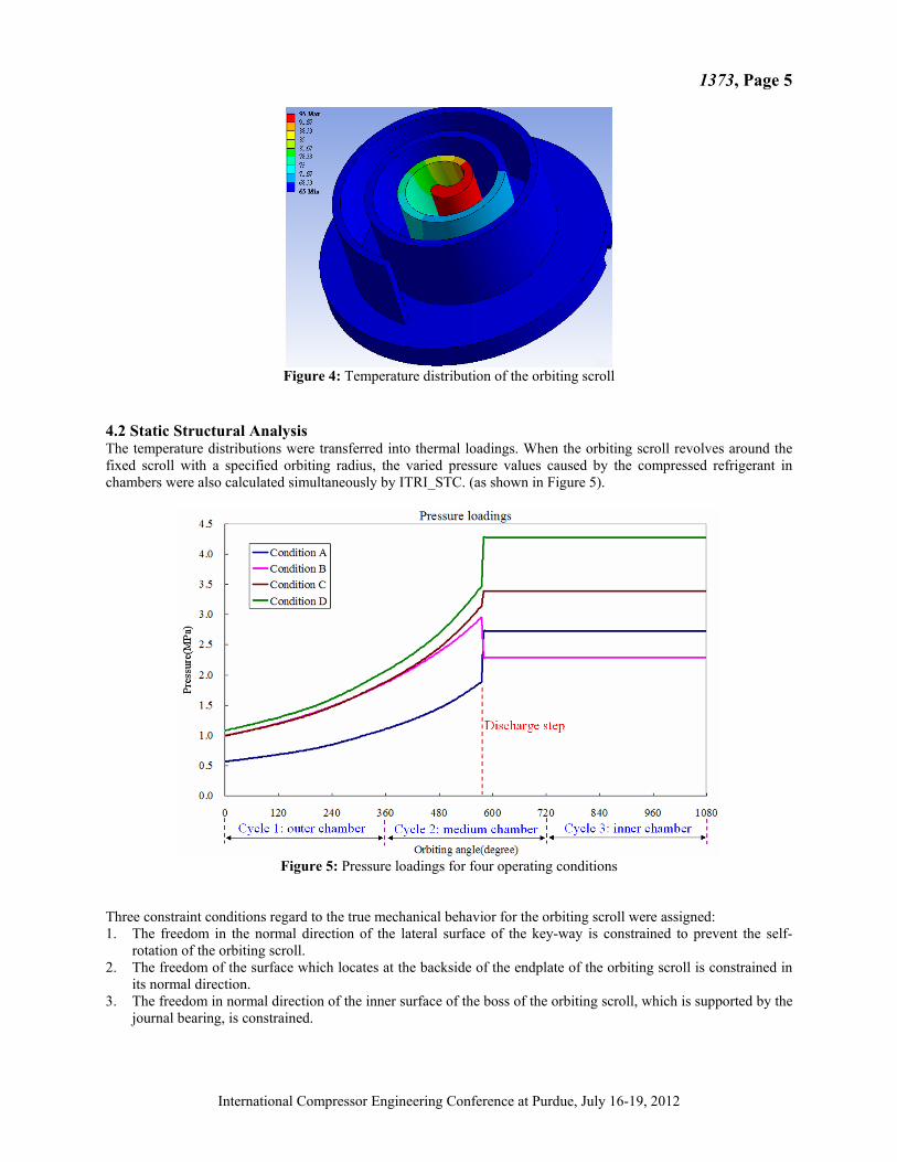
Figure 4: Temperature distribution of the orbiting scroll
4.2 Static Structural Analysis The temperature distributions were transferred into thermal loadings. When the orbiting scroll revolves around the fixed scroll with a specified orbiting radius, the varied pressure values caused by the compressed refrigerant in chambers were also calculated simultaneously by ITRI_STC. (as shown in Figure 5).
Figure 5: Pressure loadings for four operating conditions
Three constraint conditions regard to the true mechanical behavior for the orbiting scroll were assigned: 1. The freedom in the normal direction of the lateral surface of the key-way is constrained to prevent the self-
rotation of the orbiting scroll. 2. The freedom of the surface which locates at the backside of the endplate of the orbiting scroll is constrained in
its normal direction. 3. The freedom in normal direction of the inner surface of the boss of the orbiting scroll, which is supported by the
journal bearing, is constrained.
International Compressor Engineering Conference at Purdue, July 16-19, 2012

1373, Page 6
5. RESULTS AND DISCUSSIONS
We selected the outer top curve of the scroll warp for observing deformation variations ( shown in Figure 6a ) because of past experience in CAE analysis for the scroll pair. Similarly, the outer end-plate curve of the scroll warp ( Figure 6b ) was selected for von-Mises stress variations. Figure 7(a) showed the total deformation variation in the outer top curve with different orbiting angles(steps) and involute curve length under operating condition A(a under-compression condition). It found that the maximum deformation was 0.05 mm at the orbiting angle 180°, and occurred in the innermost part of the involute curve (lower than the involute curve length 126 mm). The maximum von-Mises stress was close to 50 MPa and also occurred in the innermost part of the involute curve. This result showed that the innermost part of the scroll wrap suffered the most dramatic deformation and stress during a orbiting cycle. Figure 8(a) showed the total deformation under condition B(a over-compression condition). The maximum value was 0.034 mm near to the orbiting angle 210°(which means the discharge angle) and occurred on the innermost part of the involute curve, too. At other angles the maximum deformation lowered 15% (from 0.025 to 0.03 mm) in average. Figure 8(b) showed the maximum von-Mises stress was near 37.5 MPa at the discharge angle and occurred on the innermost part of the involute curve. Hence under condition B, the maximum deformation and stress were both alleviated. The condition C was a slight under-compression condition. Figure 9(a) showed that the maximum deformation was 0.044 mm at the orbiting angle 30° (which is close to the initial angle) and also occurred on the innermost part of the involute curve. However the deformation at the discharge angle was 0.037 mm. This showed that the maximum deformation was not necessarily occurred at the discharge angle, different working conditions could affect it. But it's location was invariably in the innermost part of the involute curve. Figure 9(b) showed the maximum von-Mises stress was close to 45 MPa (at the orbiting angle 60°) and occurred at the innermost part of the involute curve. So the maximum deformation and stress occurred at different orbiting angles, but both located in the innermost part under this slight under-compression condition. Finally the total deformation under condition D (with under-compression but severer operating pressures) was shown in Figure 10(a). It found that the maximum deformation was 0.059 mm near to the orbiting angle 180°, and also occurred on the innermost part of the involute curve. After discharge, the maximum deformation was lowered dramatically (from 0.035 to 0.05 mm in average). Figure 10(b) also showed that the maximum von-Mises stress (close to 60 MPa) was at several different orbiting angles but both occurred in the innermost part of the involute curve. Hence condition D had the biggest maximum deformation and stress, and those values occurred at several different orbiting angles depending on various pressure and thermal loadings. However both them are all occurred in the innermost part of the involute curve no matter what operating conditions.
Figure 6: (a)Outer top curve of the scroll wrap (b)Outer end-plate curve of the scroll wrap
International Compressor Engineering Conference at Purdue, July 16-19, 2012

1373, Page 7
Figure 7: (a)Total deformation (b)von-Mises stress for the orbiting scroll under condition A
Figure 8: (a)Total deformation (b)von-Mises stress of the orbiting scroll under condition B
Figure 9: (a)Total deformation (b)von-Mises stress of the orbiting scroll under condition C
International Compressor Engineering Conference at Purdue, July 16-19, 2012

1373, Page 8
Figure 10: (a)Total deformation (b)von-Mises stress of the orbiting scroll under condition D
6. CONCLUSIONS This study integrated 3D CAD with finite element analysis (FEA) to investigate a key component in scroll compressor—the orbiting scroll. Both thermal and pressure loadings obtained from ITRI_STC package for a complete orbiting cycle were adopted as boundaries. Four operating conditions were discussed and summarized below:
• Under condition A (under-compression), the innermost part of the scroll wrap generated the maximum deformation and stress. Under condition B (over-compression but with lower operating pressures), the maximum deformation and stress both occurred at the discharge angle and in the innermost part of the involute curve too.
• Under slight under-compression (condition C), the maximum deformation was not necessarily occurred at the discharge angle, however the maximum deformation and stress were still in the innermost part of the involute curve.
• The maximum deformation under condition D (under-compression with severer operating pressures) occurred near to the discharge angle. After discharge, the deformation was lowered dramatically. The maximum deformation and stress are both occurred in the innermost part of the involute curve whether any conditions operated.
• The suggestions considering design and machining for the scroll pair can be provided by this procedure. It assists designers not only to improve their design for the weaker structural parts, but also reduce the time and cost in developing new scroll type compressors.
REFERENCES
K.T. Ooi, J. Zhu, Convective heat transfer in a scroll compressor chamber: a 2-D simulation International Journal of
Thermal Sciences 43- 7( 2004), pp.677-688. M.M. Cui, Numerical Study of Unsteady Flows in a Scroll Compressor, J. Fluids Eng. 128(2006), 947. K. Suefuji, M. Shiibayshi, R. Minakate, K. Tojo, Derfomation anlysis of scroll members in hermetic scroll
compressors for air conditioners, In: Proceedings of International Compressor Engineering Conference at Purdue, 1988, pp.583–589.
D. Yu, T.A. Ameel, R.O. Warrington, Thermal and static finite element analysis of fixed scroll deformation, In: Proceedings of International Compressor Engineering Conference at Purdue, 1996, pp.465–470.
J.M. O'Leary, T.J. Weadock, G.W. Gatecliff, Scroll Compressor Cupping Analysis, In: Proceedings of International Compressor Engineering Conference at Purdue, 1998, pp.613–617.
L. Wang, Y.Y. Zhao, C. Xiong, L. Li, Application of a FEA model for conformability calculation of tip seal in compressor, In: Proceedings of International Compressor Engineering Conference at Purdue, 2008, C1150.
International Compressor Engineering Conference at Purdue, July 16-19, 2012

1373, Page 9
C.C. Lin, Y.C. Chang, K.Y. Liang, C.H. Hung, Temperature and thermal deformation analysis on scrolls of scroll
compressor, Applied thermal engineering 25(2005), pp. 1724–1739. B.K. Yoo, B.C. Lee, M.K. Kiem, S.C. Kim, Structure Design of a Scroll Compressor Using CAE Analysis, In
Proceedings of International Compressor Engineering Conference at Purdue, 2006, C051. B. Peng, H. Zhang, L. Zhang, Z. Liu, Stress and deformation analysis of twin-spiral scroll plate based on CAE, In:
Proceedings of International Compressor Engineering Conference at Purdue, 2008, C1372. Y.B. Yang, Y.J. Tang, Y.C. Chang, Static and dynamic analysis on R410A scroll compressor components, In:
Proceedings of International Compressor Engineering Conference at Purdue, 2010, C1180. D. Gross, C. Ancel, L. guglielmi, Fatigue design for scroll compressor wraps, n: Proceedings of International
Compressor Engineering Conference at Purdue, 2010, C1490. Madenci E., Guven, I., 2005, The Finite Element Method and Applications in Engineering Using ANSYS, Springer. Stolarski, T., Nakasone, Y., and Yoshimoto S., 2007, Engineering Analysis with ANSYS Software, Butterworth-
Heinemann
ACKNOWLEDGEMENT The authors would like to express grateful acknowledgement for financial support from the Bureau of Energy, Ministry of Economic Affairs. This work was under the auspices of the Green Energy and Environment Research Laboratories, Industrial Technology Research Institute in Taiwan
International Compressor Engineering Conference at Purdue, July 16-19, 2012