Mobile App benefits for your Real Estate Business - Smarther Technologies

AboveAir™ 2x4 Spot CoolersAboveAir Technologies (ASC-L22)1
AboAboAboAboAbovvvvveAireAireAireAireAir™ above-the-ceiling air conditioners (ASC-L22)
Engineering Manual
1 to 3 Tons“Spot-Cooler & Ducted”
Features & Benefits• 1 to 3 Ton Capacities
• Comfort Applications- General Office Spaces- Conference Rooms- Classrooms
• Precision Applications- Computer / Server Rooms- Telecom Rooms- Labs / Hospitals
• 2’ by 4’ Ductless Spot Cooler orOptional Ducted Evaporator
• DX Air, Water & Glycol Cooled,Chilled Water & Heat Pump
• Total Temp & Humidity Control- Optional Steam Humidifier- Optional Heat/Reheat via
Electric, Hot Gas, Hot Water,Steam or Heat Pump
• Microprocessor Controls & More!
SCSCSCSCSC™ SpotCool2 x 4 Packaged & Split
Ceiling Mounted A/C’s(DX & CW Systems)
MEA230-06-E
R407c & R410aR407c & R410aR407c & R410aR407c & R410aR407c & R410a

AboveAir™ 2x4 Spot Coolers AboveAir Technologies (ASC-L22)2 Introduction
INTRODUCTION
AboAboAboAboAbovvvvveeeeeAirAirAirAirAir™™™™™ ceiling mounted airconditioners & heat pumps are thespace saving environmental controlsolution to your comfort and preci-sion cooling needs. Available in awide variety of cooling methodsand cabinet configurations includ-ing a full range of options,AboAboAboAboAbovvvvveeeeeAirAirAirAirAir™™™™™ ceiling mounted AirConditioners are a step above!
R407c or Optional R410a Refrigerant Hidden above-the-ceiling installation Space saving “spot-cooler” air pattern Variety of cooling methods Self-contained & split systems Flexible options and accessories Energy efficient operation Low sound operation
ContentsIntroduction ................................................ 2
Features and Benefits ............................... 3
Performance Data ................................... 4-6
Electrical Data ......................................... 7-9
Guide Specifications .......................... 10-14
Dimensional Data ................................ 15-25
Model Nomenclature ............................... 27
Approximate Unit Weights (lbs) .............. 27
AccessPanel
(evaporator
blower / coil)
AccessPanel
(condenser
blwr/mtr)AccessPanel
(electrical
box)
AccessPanel
(compressor,
cond coil)
AccessPanel
(evaporator
blower / coil)
AccessPanel
(electrical
box)
AccessPanel
(evaporator
blower / coil)
AccessPanel
(electrical
box)
AccessPanel
(compressor,
coax, vlv)
SPA-( )DX - Air Cooled Self-Contained
SPH/SPE & CCU/CCX -( )DX - Air Cooled Split with Centrifugal BlowerIndoor / Outdoor Remote Condensing Unit & Condensers
SPW & SPG-( )DX - Water/Glycol Cooled Self-Contained
SPC-( )Chilled Water Air Handling Units
DX - Air Cooled
DX - Water/Glycol Cooled
Chilled Water Systems
AccessPanel
(evaporator
blower / coil)
AccessPanel
(electrical
box)
AccessPanel
(evaporator
blower / coil)
AccessPanel
(electrical
box)
SPH/SPE & XPU/XP1-( )DX - Air Cooled Split with Propeller FanOutdoor Remote Condensing Unit &Condensers
* Split Water/Glycolalso Available!
(SPH & CWU/CGU)

AboveAir™ 2x4 Spot CoolersAboveAir Technologies (ASC-L22)3Features & Benefits
FEATURES & BENEFITS
Select Options:• Digital Heat/Cool Thermostats• Temp & Humid Microprocessor Controls with
Alarms and Optional BMS Communications• Steam Canister Humidifier• Heating Mode with Electric, Hot Water,
Steam or Heat Pump Heating• Dehumidification Mode with Electric, Hot
Gas, Hot Water or Steam Reheat• High Efficiency Air Filtration• Low Ambient Head Pressure Control• 2 & 3-way 150 psig or 350 psig Water/
Glycol Cooled Regulating Valves• Hot Gas Bypass
Select Accessories:• Condensate Pumps• Main Power Electrical Disconnects• Firestats• Smoke Detectors• Remote Water Detectors• Compressor Sound Jackets• Hanging Vibration Isolators• Glycol Pump Packages & Drycoolers• ... and more!
MEA230-06-E
AboveAir™™™™™ Spot Coolers are designedto meet your unique application dependentrequirements. Select from a wide range ofoptions and configurations:
Spot Cooler with IntegralReturn-Filter & 3-Way Supply Grille
Optional Ducted Supply &Return Connections
Access
Panel(evaporator
blower / coil)
EvaporatorSupply Air Outlet
EvaporatorReturn Air Inlet
AccessPanel
(evaporator
blower / coil)
AccessPanel
(electrical
box)
EvaporatorSupply Air Outlet
EvaporatorReturn Air Inlet

AboveAir™ 2x4 Spot Coolers AboveAir Technologies (ASC-L22)4 Performance Data
Performance Data (SC™ 2x4) - DX 1 To 3 Tons
Nominal Size 1.0 Ton 1.5 Tons 2.0 Tons 2.5 Tons 3.0 Tons
Air Cooled Model SPA, SPE & SPH-012 SPA, SPE & SPH-018 SPA, SPE & SPH-024 SPA, SPE & SPH-030 SPA, SPE & SPH-036
AIRCOOLED
DX
80°F DB / 67°F WB, 50% RH
Total BTUH 13,900 20,000 25,300 33,700 37,000
Sensible BTUH 10,200 16,200 18,400 23,100 26,200
75°F DB / 62.5°F WB, 50% RH
Total BTUH 13,100 18,300 22,900 31,000 33,700
Sensible BTUH 10,600 15,900 18,400 22,800 25,400
72°F DB / 60°F WB, 50% RH
Total BTUH 12,500 17,400 22,100 29,500 32,100
Sensible BTUH 10,400 15,600 19,100 22,500 24,700
Water Cooled Model SPW-012 SPW-018 SPW-024 SPW-030 SPW-036
WATERCOOLED
DX
80°F DB / 67°F WB, 50% RH
Total BTUH 14,700 20,000 26,800 35,900 39,300
Sensible BTUH 10,200 16,700 19,100 24,400 27,400
75°F DB / 62.5°F WB, 50% RH
Total BTUH 13,800 19,400 24,400 33,000 35,900
Sensible BTUH 10,400 16,400 18,900 24,200 26,600
72°F DB / 60°F WB, 50% RH
Total BTUH 13,300 18,400 23,200 31,500 34,200
Sensible BTUH 10,800 16,000 18,600 23,800 25,900
Glycol Cooled Model SPG-012 SPG-018 SPG-024 SPG-030 SPG-036
GLYCOLCOOLED
DX
80°F DB / 67°F WB, 50% RH
Total BTUH 13,600 19,000 24,000 33,000 35,300
Sensible BTUH 10,400 15,800 18,300 23,200 25,400
75°F DB / 62.5°F WB, 50% RH
Total BTUH 12,500 17,400 23,100 30,300 32,200
Sensible BTUH 10,400 15,500 18,400 22,900 24,700
72°F DB / 60°F WB, 50% RH
Total BTUH 11,900 16,600 22,000 28,900 30,400
Sensible BTUH 10,100 15,200 19,000 22,500 24,500
GENERAL SHARED DATA
ALL DXMODELS
Electric Reheat / Heat - BTUH includes evaporator motor heat, (Optional)
Capacity @ 208V BTUH (KW) 16,040 (4.7) 16,040 (4.7) 16,610 (4.9) 16,610 (4.9) 17,185 (5.0)
Capacity @ 230V BTUH (KW) 17,675 (5.2) 17,675 (5.2) 18,245 (5.3) 18,245 (5.3) 18,820 (5.5)
Capacity @ 460V BTUH (KW) 16,960 (5.0) 16,960 (5.0) 17,535 (5.1) 17,535 (5.1) 18,105 (5.3)
Cap. @ 277/480V BTUH (KW) 17,675 (5.2) 17,675 (5.2) 18,245 (5.3) 18,245 (5.3) 18,820 (5.5)
Hot Gas Reheat - (Optional)
Capacity BTUH 12,690 18,210 21,350 26,060 30,125
Hot Water & Steam Reheat / Heat - (Optional)
Capacity See Page 6 for Complete Hot Water & Steam Heating Coil Performance Data
Steam Canister Humidifier - (Optional)
Steam Canister LBS/HR 5 5 5 5 5
Evaporator Blower / Motor - Direct Drive, DWDI Centrifugal
Airflow Rate CFM 500 750 900 1,000 1,200
E.S.P. IN WG 0.3 0.3 0.3 0.3 0.3
Blower Motor HP 1/4 1/4 1/2 1/2 3/4
Evaporator Coil - Aluminum Fin, Copper Tube
Rows / Face Area NO / FT2 3 / 2.0 3 / 2.0 3 / 2.0 3 / 2.5 3 / 2.5
Filters - 20% Dust Spot Efficient (Spot Cooler Version)
Nominal Size (NO) IN (1) 20 x 20 x 1 (1) 20 x 20 x 1 (1) 20 x 20 x 1 (1) 20 x 20 x 1 (1) 20 x 20 x 1
Compressor - Heat Pump Duty Scroll
Qty., Horespower (NO) HP (1) 1.25 (1) 1.5 (1) 2.0 (1) 2.5 (1) 3.0
Connection Sizes Condensate Drain FPT IN 3/4 3/4 3/4 3/4 3/4
Humidifier Inlet OD IN 1/4 1/4 1/4 1/4 1/4
AboveAir™ 2x4 Spot CoolersAboveAir Technologies (ASC-L22)5Performance Data
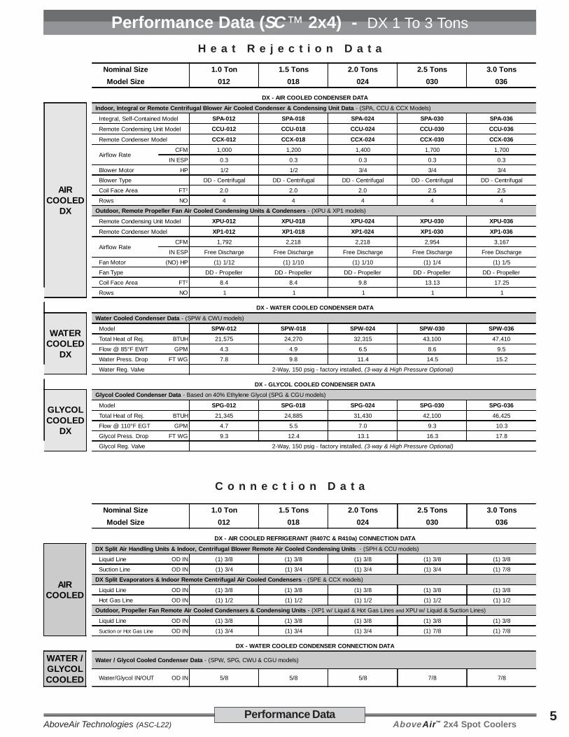
Performance Data (SC™ 2x4) - DX 1 To 3 TonsH e a t R e j e c t i o n D a t a
C o n n e c t i o n D a t a
Nominal Size 1.0 Ton 1.5 Tons 2.0 Tons 2.5 Tons 3.0 TonsModel Size 012 018 024 030 036
DX - AIR COOLED CONDENSER DATA
AIRCOOLED
DX
Indoor, Integral or Remote Centrifugal Blower Air Cooled Condenser & Condensing Unit Data - (SPA, CCU & CCX Models)
Integral, Self-Contained Model SPA-012 SPA-018 SPA-024 SPA-030 SPA-036
Remote Condensing Unit Model CCU-012 CCU-018 CCU-024 CCU-030 CCU-036
Remote Condenser Model CCX-012 CCX-018 CCX-024 CCX-030 CCX-036
Airflow RateCFM 1,000 1,200 1,400 1,700 1,700
IN ESP 0.3 0.3 0.3 0.3 0.3
Blower Motor HP 1/2 1/2 3/4 3/4 3/4
Blower Type DD - Centrifugal DD - Centrifugal DD - Centrifugal DD - Centrifugal DD - Centrifugal
Coil Face Area FT2 2.0 2.0 2.0 2.5 2.5
Rows NO 4 4 4 4 4
Outdoor, Remote Propeller Fan Air Cooled Condensing Units & Condensers - (XPU & XP1 models)
Remote Condensing Unit Model XPU-012 XPU-018 XPU-024 XPU-030 XPU-036
Remote Condenser Model XP1-012 XP1-018 XP1-024 XP1-030 XP1-036
Airflow RateCFM 1,792 2,218 2,218 2,954 3,167
IN ESP Free Discharge Free Discharge Free Discharge Free Discharge Free Discharge
Fan Motor (NO) HP (1) 1/12 (1) 1/10 (1) 1/10 (1) 1/4 (1) 1/5
Fan Type DD - Propeller DD - Propeller DD - Propeller DD - Propeller DD - Propeller
Coil Face Area FT2 8.4 8.4 9.8 13.13 17.25
Rows NO 1 1 1 1 1
DX - WATER COOLED CONDENSER DATA
WATERCOOLED
DX
Water Cooled Condenser Data - (SPW & CWU models)
Model SPW-012 SPW-018 SPW-024 SPW-030 SPW-036
Total Heat of Rej. BTUH 21,575 24,270 32,315 43,100 47,410
Flow @ 85°F EWT GPM 4.3 4.9 6.5 8.6 9.5
Water Press. Drop FT WG 7.8 9.8 11.4 14.5 15.2
Water Reg. Valve 2-Way, 150 psig - factory installed, (3-way & High Pressure Optional)
DX - GLYCOL COOLED CONDENSER DATA
GLYCOLCOOLED
DX
Glycol Cooled Condenser Data - Based on 40% Ethylene Glycol (SPG & CGU models)
Model SPG-012 SPG-018 SPG-024 SPG-030 SPG-036
Total Heat of Rej. BTUH 21,345 24,885 31,430 42,100 46,425
Flow @ 110°F EGT GPM 4.7 5.5 7.0 9.3 10.3
Glycol Press. Drop FT WG 9.3 12.4 13.1 16.3 17.8
Glycol Reg. Valve 2-Way, 150 psig - factory installed, (3-way & High Pressure Optional)
Nominal Size 1.0 Ton 1.5 Tons 2.0 Tons 2.5 Tons 3.0 TonsModel Size 012 018 024 030 036
DX - AIR COOLED REFRIGERANT (R407C & R410a) CONNECTION DATA
AIRCOOLED
DX Split Air Handling Units & Indoor, Centrifugal Blower Remote Air Cooled Condensing Units - (SPH & CCU models)
Liquid Line OD IN (1) 3/8 (1) 3/8 (1) 3/8 (1) 3/8 (1) 3/8
Suction Line OD IN (1) 3/4 (1) 3/4 (1) 3/4 (1) 3/4 (1) 7/8
DX Split Evaporators & Indoor Remote Centrifugal Air Cooled Condensers - (SPE & CCX models)
Liquid Line OD IN (1) 3/8 (1) 3/8 (1) 3/8 (1) 3/8 (1) 3/8
Hot Gas Line OD IN (1) 1/2 (1) 1/2 (1) 1/2 (1) 1/2 (1) 1/2
Outdoor, Propeller Fan Remote Air Cooled Condensers & Condensing Units - (XP1 w/ Liquid & Hot Gas Lines and XPU w/ Liquid & Suction Lines)
Liquid Line OD IN (1) 3/8 (1) 3/8 (1) 3/8 (1) 3/8 (1) 3/8
Suction or Hot Gas Line OD IN (1) 3/4 (1) 3/4 (1) 3/4 (1) 7/8 (1) 7/8
DX - WATER COOLED CONDENSER CONNECTION DATA
WATER /GLYCOLCOOLED
Water / Glycol Cooled Condenser Data - (SPW, SPG, CWU & CGU models)
Water/Glycol IN/OUT OD IN 5/8 5/8 5/8 7/8 7/8

AboveAir™ 2x4 Spot Coolers AboveAir Technologies (ASC-L22)6 Performance Data
Performance Data (SC™ 2x4) - Chilled Water 1 To 3 Tons
Nominal Size 1.0 Ton 1.5 Tons 2.0 Tons 2.5 Tons 3.0 Tons
Chilled Water Unit Model SPC-012 SPC-018 SPC-024 SPC-030 SPC-036
CHILLEDWATER
SYSTEMS
Cooling Capacity - 45°F Entering Chilled Water (0% Glycol)
80°F DB / 67°F WB, 50% RH
Total BTUH 14,400 21,900 26,900 36,600 41,400
Sensible BTUH 10,800 16,900 20,400 25,400 29,300
75°F DB / 62.5°F WB, 50% RH
Total BTUH 11,500 17,600 21,500 28,700 32,600
Sensible BTUH 10,000 15,800 18,900 23,100 26,700
72°F DB / 60°F WB, 50% RH
Total BTUH 10,000 15,400 18,700 24,600 28,000
Sensible BTUH 9,400 14,900 17,800 21,500 25,000
Chilled Water Coil / Valve - Aluminum Fin, Copper Tube
Flow Rate / Coil PD GPM/FT 3.0 / (0.5) 4.5 / (1.0) 6.0 (1.9) 7.3 (11.1) 8.3 / (13.9)
Rows / Face Area NO / FT2 4 / 2.0 4 / 2.0 4 / 2.0 4 / 2.5 4 / 2.5
Standard Valve BTUH 2-Way, 300 psig - factory installed, (3-Way & Higher Pressure Optional)
Evaporator Blower / Motor - Direct Drive, DWDI Centrifugal
Airflow Rate @ E.S.P. CFM / IN WG 500 @ 0.3 750 @ 0.3 900 @ 0.3 1,000 @ 0.3 1,200 @ 0.3
Blower Motor HP 1/4 1/4 1/2 1/2 3/4
Electric Reheat / Heat - BTUH includes evaporator motor heat, (Optional)
Capacity @ 208V BTUH (KW) 16,040 (4.7) 16,040 (4.7) 16,610 (4.9) 16,610 (4.9) 17,185 (5.0)
Capacity @ 230V BTUH (KW) 17,675 (5.2) 17,675 (5.2) 18,245 (5.3) 18,245 (5.3) 18,820 (5.5)
Capacity @ 460V BTUH (KW) 16,960 (5.0) 16,960 (5.0) 17,535 (5.1) 17,535 (5.1) 18,105 (5.3)
Capacity @ 277/480V BTUH (KW) 17,675 (5.2) 17,675 (5.2) 18,245 (5.3) 18,245 (5.3) 18,820 (5.5)
Hot Water & Steam Reheat / Heat - (Optional)
Capacity See Below for Complete Hot Water & Steam Heating Coil Performance Data
Steam Canister Humidifier - (Optional)
Steam Canister LBS/HR 5 5 5 5 5
Filters - 20% Dust Spot Efficient (Spot Cooler Version)
Nominal Size (NO) IN (1) 20 x 20 x 1 (1) 20 x 20 x 1 (1) 20 x 20 x 1 (1) 20 x 20 x 1 (1) 20 x 20 x 1
Connection Sizes Chilled Water In/Out OD IN 5/8 5/8 5/8 7/8 7/8
Condensate Drain FPT IN 3/4 3/4 3/4 3/4 3/4
Humidifier Inlet OD IN 1/4 1/4 1/4 1/4 1/4
HOT WATER&
STEAM
HEAT/REHEAT
Nominal Unit Size 1.0 Ton 1.5 Tons 2.0 Tons 2.5 Tons 3.0 Tons
Std Airflow Rate CFM 500 750 900 1,000 1,200
HOT WATER HEATING COIL - (OPTIONAL)
Hot Water Heating Coil - @ 180°F EWT / 160°F LWT, 70°F DB EAT
Heating Capacity BTUH 21,660 30,320 33,880 40,240 45,280
Flow Rate / Fluid PD GPM / FT H20 2.3 / (0.4) 3.2 / (0.6) 3.5 / (0.7) 4.2 / (1.3) 4.8 / (1.7)
LAT °F DB 113.5 106.4 103.8 106.2 103.9
STEAM HEATING COIL - (OPTIONAL) Steam Heating Coil - @ 5 PSIG (227.1°F) Supply Steam, 70°F DB EAT
Heating Capacity BTUH 33,860 45,980 50,940 52,840 58,390
Condensate LB/HR 35 48 53 55 61
Steam Pr. Drop FT H2O 0.1 0.1 0.1 0.1 0.1
LAT °F DB 140.4 127.3 122.9 119.4 115.5
Hot Water & Steam Heating Coil Physical Data
Rows / Face Area NO / FT2 1 / (2.0) 1 / (2.0) 1 / (2.0) 1 / (2.5) 1 / (2.5)
HW/STM IN/OUT IN OD 5/8 5/8 5/8 5/8 5/8
Standard Valve TXT 2-way - field installed (3-way valves are optional)
Hot Water & Steam Reheat / Heat Performance Data

AboveAir™ 2x4 Spot CoolersAboveAir Technologies (ASC-L22)7Electrical Data
Electrical Data (SC™ 2x4) - DX Self-Contained & Split Evap
MODEL SPA-012 SPA-018 SPA-024 SPA-030 SPA-036
Power Supply 208/1/60 277/1/60 208/1/60 277/1/60 208/1/60 277/1/60 208/3/60 460/3/60 208/1/60 277/1/60 208/3/60 460/3/60 208/1/60 277/1/60 208/3/60 460/3/60
Cooling Only (or Cooling with Hot Gas Reheat, Hot Water or Steam Reheat / Heat)
FLA 15.2 12.3 15.8 12.9 20.8 17.3 16.3 8.7 23.5 19.3 18.4 9.6 28.7 23.8 24.3 10.4
MCA 17.5 14.1 18.2 14.8 24.0 20.0 18.4 10.0 27.0 22.4 20.7 11.0 33.2 27.8 27.7 11.9
MOP 25 20 25 20 35 30 25 15 40 30 25 15 50 40 40 15
with Electric Heat (No Electric Reheat or Humidifier)
FLA 26.3 20.1 26.3 20.1 28.1 21.3 17.9 8.7 28.1 21.3 18.4 9.6 29.5 23.8 24.3 10.4
MCA 32.9 25.1 32.9 25.1 35.1 26.6 22.4 10.1 35.1 26.6 22.4 11.0 36.9 27.8 27.7 11.9
MOP 35 30 35 30 35 30 25 15 40 30 25 15 50 40 40 15
with Electric Reheat/Heat (No Humidifier)
FLA 39.3 30.4 39.9 31.0 44.9 35.4 30.2 15.0 47.6 37.4 32.3 15.9 52.8 41.9 38.2 16.7
MCA 47.6 36.7 48.3 37.4 54.1 42.6 35.8 17.8 57.1 45.0 38.0 18.9 63.3 50.4 45.1 19.8
MOP 50 40 50 40 60 45 40 20 60 50 40 20 70 60 50 20
with Humidifier with or without Hot Gas Reheat, Hot Water/Steam Reheat/Heat(No Electric Reheat/Heat)
FLA 23.4 18.5 24.0 19.1 29.0 23.5 24.5 12.4 31.7 25.5 26.6 13.3 36.9 30.0 32.5 14.1
MCA 25.7 20.3 26.4 21.0 32.2 26.2 26.6 13.7 35.2 28.6 28.9 14.7 41.4 34.0 35.9 15.6
MOP 30 25 35 25 45 35 30 15 45 40 35 20 45 50 45 20
with Electric Heat (No Electric Reheat) & Humidifier
FLA 34.5 26.3 34.5 26.3 36.3 27.5 26.1 12.4 36.3 27.5 26.6 13.3 37.7 30.0 32.5 14.1
MCA 41.1 31.3 41.1 31.3 43.3 32.8 30.6 13.8 43.3 32.8 30.6 14.7 45.1 34.0 35.9 15.6
MOP 45 35 45 35 45 35 35 15 45 40 35 20 50 50 45 20
with Electric Reheat/Heat & Humidifier
FLA 39.3 30.4 39.9 31.0 44.9 35.4 30.2 15.0 47.6 37.4 32.3 15.9 52.8 41.9 38.2 16.7
MCA 47.6 36.7 48.3 37.4 54.1 42.6 35.8 17.8 57.1 45.0 38.0 18.9 63.3 50.4 45.1 19.8
MOP 50 40 50 40 60 45 40 20 60 50 40 20 70 60 50 20
DX - Air Cooled, Self-Contained
Notes:1) FLA = Full Load Amps; MCA = Min Circuit Amps; MOP = Max Overcurrent Protection (Max Fuse Size)2) 277/1/60 systems may require factory provided field installed step-down transformer.3) - - - - Consult local AboveAir Sales Representative for non-cataloged system power supply information.
DX - Water/Glycol Cooled Self-Contained & DX Split EvapMODEL SPW, SPG & SPE-012 SPW, SPG & SPE-018 SPW, SPG & SPE-024 SPW, SPG & SPE-030 SPW, SPG & SPE-036
Power Supply 208/1/60 277/1/60 208/1/60 277/1/60 208/1/60 277/1/60 208/3/60 460/3/60 208/1/60 277/1/60 208/3/60 460/3/60 208/1/60 277/1/60 208/3/60 460/3/60
Cooling Only (or Cooling with Hot Gas Reheat, Hot Water or Steam Reheat / Heat)
FLA 11.2 9.1 11.8 9.7 16.8 14.1 12.3 6.9 18.1 15.4 13.0 7.4 23.3 19.9 18.9 8.2
MCA 13.5 10.9 14.2 11.6 20.0 16.8 14.4 8.2 21.6 18.5 15.3 8.8 27.8 23.9 22.3 9.7
MOP 20 15 20 15 30 25 20 15 35 30 20 15 45 35 35 15
with Electric Heat (No Electric Reheat or Humidifier)
FLA 26.3 20.1 26.3 20.1 28.1 21.3 17.9 8.1 28.1 21.3 17.9 8.1 29.5 22.0 19.3 8.5
MCA 32.9 25.1 32.9 25.1 35.1 26.6 22.4 10.1 35.1 26.6 22.4 10.1 36.9 27.5 24.1 10.6
MOP 35 30 35 30 40 30 25 15 40 30 25 15 45 35 35 15
with Electric Reheat/Heat (No Humidifier)
FLA 35.3 27.2 35.9 27.8 40.9 32.2 26.2 13.2 42.2 33.5 26.9 13.7 47.4 38.0 32.8 14.5
MCA 43.6 33.5 44.3 34.2 50.1 39.4 31.8 16.0 51.7 41.1 32.6 16.7 57.9 46.5 39.7 17.6
MOP 45 35 45 35 60 45 35 20 60 45 35 20 60 50 45 20
with Humidifier with or without Hot Gas Reheat, Hot Water/Steam Reheat/Heat(No Electric Reheat/Heat)
FLA 19.4 15.3 20.0 15.9 25.0 20.3 20.5 10.6 26.3 21.6 21.2 11.1 31.5 26.1 27.1 11.9
MCA 21.7 17.1 22.4 17.8 28.2 23.0 22.6 11.9 29.8 24.7 23.5 12.5 36.0 30.1 30.5 13.4
MOP 30 20 30 25 40 35 30 15 40 35 30 15 50 45 40 15
with Electric Heat (No Electric Reheat) & Humidifier
FLA 34.5 26.3 34.5 26.3 36.3 27.5 26.1 11.8 36.3 27.5 26.1 11.8 37.7 28.2 27.5 12.2
MCA 41.1 31.3 41.1 31.3 43.3 32.8 30.6 13.8 43.3 32.8 30.6 13.8 45.1 33.7 32.3 14.3
MOP 45 35 45 35 45 35 35 15 45 35 35 15 50 45 40 15
with Electric Reheat/Heat & Humidifier
FLA 35.3 27.2 35.9 27.8 40.9 32.2 26.2 13.2 42.2 33.5 26.9 13.7 47.4 38.0 32.8 14.5
MCA 43.6 33.5 44.3 34.2 50.1 39.4 31.8 16.0 51.7 41.1 32.6 16.7 57.9 46.5 39.7 17.6
MOP 45 35 45 35 60 45 35 20 60 45 35 20 60 50 45 20

AboveAir™ 2x4 Spot Coolers AboveAir Technologies (ASC-L22)8
Notes:1) FLA = Full Load Amps; MCA = Min Circuit Amps; MOP = Max Overcurrent Protection (Max Fuse Size)2) 277/1/60 systems may require factory provided field installed step-down transformer.3) - - - - Consult local AboveAir Sales Representative for non-cataloged system power supply information.
Electrical Data
Electrical Data (SC™ 2x4) - DX Air Cooled, Remote Cond Units & Conds
Outdoor, Pad Mtd - DX - Air Cooled, Remote Condensing Units & CondensersXPU - Outdoor Propeller Fan
Air Cooled Remote Condensing UnitsXP1 - Outdoor Propeller Fan
Air Cooled Remote Condensers
Power Supply 208/1/60 277/1/60 208/3/60 460/3/60 Power Supply 208/1/60 277/1/60 460/1/60
XPU-012 XP1-012
FLA 9.5 7.1
- - - - - - - -
FLA 0.5 0.4 0.6
MCA 11.8 8.8 MCA 0.6 0.5 0.8
MOP 20 15 MOP 15 15 15
XPU-018 XP1-018
FLA 10.4 7.8
- - - - - - - -
FLA 0.8 0.6 0.6
MCA 17.6 13.2 MCA 1.0 0.8 0.8
MOP 30 20 MOP 15 15 15
XPU-024 XP1-024
FLA 13.6 10.2 9.1 5.2 FLA 0.8 0.6 0.7
MCA 16.8 12.6 11.2 6.3 MCA 1.0 0.8 0.9
MOP 25 20 20 15 MOP 15 15 15
XPU-030 XP1-030
FLA 15.5 11.6 11.9 6.3 FLA 1.4 1.1 0.7
MCA 19.0 14.3 14.5 7.7 MCA 1.8 1.3 0.9
MOP 30 25 20 15 MOP 15 15 15
XPU-036 XP1-036
FLA 19.0 14.3 14.6 6.6 FLA 1.1 0.8 0.6
MCA 23.5 17.6 18.0 8.1 MCA 1.4 1.0 0.8
MOP 40 30 30 15 MOP 15 15 15
Indoor, Ceiling Mtd - DX - Air Cooled, Remote Condensing Units & CondensersCCU - Indoor (Ceiling Mtd), Centrifugal Blower
Air Cooled Remote Condensing UnitsCCX - Indoor (Ceiling Mtd), Centrifugal Blower
Air Cooled Remote Condensers
Power Supply 208/1/60 277/1/60 208/3/60 460/3/60 Power Supply 208/1/60 277/1/60 460/1/60
CCU-012 CCX-012
FLA 13.0 10.3
- - - - - - - -
FLA 4.0 3.2 1.8
MCA 15.3 12.1 MCA 5.0 4.0 2.3
MOP 20 15 MOP 15 15 15
CCU-018 CCX-018
FLA 13.6 10.9
- - - - - - - -
FLA 4.0 3.2 1.8
MCA 16.0 12.8 MCA 5.0 4.0 2.3
MOP 25 20 MOP 15 15 15
CCU-024 CCX-024
FLA 18.2 14.8 13.7 7.3 FLA 5.4 3.9 2.2
MCA 21.4 17.5 15.8 8.6 MCA 6.8 4.9 2.8
MOP 30 25 20 15 MOP 15 15 15
CCU-030 CCX-030
FLA 19.5 16.1 14.4 7.8 FLA 5.4 3.9 2.2
MCA 23.0 19.2 16.7 9.2 MCA 6.8 4.9 2.8
MOP 35 30 25 15 MOP 15 15 15
CCU-036 CCX-036
FLA 23.3 19.9 18.9 8.2 FLA 5.4 3.9 2.2
MCA 27.8 23.9 22.3 9.7 MCA 6.8 4.9 2.8
MOP 45 35 35 15 MOP 15 15 15

AboveAir™ 2x4 Spot CoolersAboveAir Technologies (ASC-L22)9Electrical Data
Electrical Data (SC™ 2x4) - Remote W/G Cond Units & Air Handlers
Notes:1) FLA = Full Load Amps; MCA = Min Circuit Amps; MOP = Max Overcurrent Protection (Max Fuse Size)2) 277/1/60 systems may require factory provided field installed step-down transformer.3) - - - - Consult local AboveAir Sales Representative for non-cataloged system power supply information.
CWU & CGU - IndoorWater & Glycol Cooled Remote Condensing Units
Power Supply 208/1/60 277/1/60 208/3/60 460/3/60
CWU & CGU-012
FLA 9.0 7.1
- - - - - - - -MCA 11.3 8.9
MOP 20 15
CWU & CGU-018
FLA 9.6 7.7
- - - - - - - -MCA 12.0 9.6
MOP 20 15
CWU & CGU-024
FLA 12.8 10.9 8.3 5.1
MCA 16.0 13.6 10.4 6.4
MOP 25 20 15 15
CWU & CGU-030
FLA 14.1 12.2 9.0 5.6
MCA 17.6 15.3 11.3 7.0
MOP 30 25 20 15
CWU & CGU-036
FLA 17.9 16.0 13.5 6.0
MCA 22.4 20.0 16.9 7.5
MOP 40 35 30 15
Indoor - DX - Water / Glycol Cooled, Remote Condensing Units
DX Split and Chilled Water - Air Handling Units
MODEL SPH & SPC-012 & 018 SPH & SPC-024 & 030 SPH & SPC-036
Power Supply 208/1/60 277/1/60 208/3/60 460/3/60 208/1/60 277/1/60 208/3/60 460/3/60 208/1/60 277/1/60 208/3/60 460/3/60
Cooling Only (or Cooling with Hot Water or Steam Heat)
FLA 2.2 2.0 2.2 1.1 4.0 3.2 4.0 1.8 5.4 3.9 5.4 2.2
MCA 2.8 2.5 2.8 1.4 5.0 4.0 5.0 2.3 6.8 4.9 6.8 2.8
MOP 15 15 15 15 15 15 15 15 15 15 15 15
with Electric Heat or Reheat/Heat (No Humidifier)
FLA 26.3 20.1 16.1 7.4 28.1 21.3 17.9 8.1 29.5 22.0 19.3 8.5
MCA 32.9 25.1 20.1 9.2 35.1 26.6 22.4 10.1 36.9 27.5 24.1 10.6
MOP 35 30 25 15 40 30 25 15 40 30 25 15
with Humidifier with or without Hot Water/Steam Heat (No Electric Reheat/Heat)
FLA 10.4 8.2 10.4 4.8 12.2 9.4 12.2 5.5 13.6 10.1 13.6 5.9
MCA 11.0 8.7 11.0 5.1 13.2 10.2 13.2 6.0 15.0 11.1 15.0 6.5
MOP 15 15 15 15 15 15 15 15 20 15 20 15
with Electric Heat or Reheat/Heat & Humidifier
FLA 34.5 26.3 24.3 11.1 36.3 27.5 26.1 11.8 37.7 28.2 27.5 12.2
MCA 41.1 31.3 28.3 12.9 43.3 32.8 30.6 13.8 45.1 33.7 32.3 14.3
MOP 45 35 30 15 45 35 35 15 50 35 35 15

AboveAir™ 2x4 Spot Coolers AboveAir Technologies (ASC-L22)10 Guide Specifications
Guide Specifications - SC™ 2x4 SpotCool (1-3 Tons)1.0 General 1.1 Summary
These specifications describe the require-ments for a horizontal ceiling mounted airconditioner. The system shall be designedto control space temperature and humidity.
The air conditioning manufacturer shalldesign and furnish all equipment in thequantities and configurations shown on theproject plans and specifications.
The system shall be provided by AboveAirTechnologies in Frederick, Maryland, USA.The system shall be listed by Intertek (ETLSemko), Inc. to conform with UL Std 1995and be certified to CAN/CSA Std C22.2 No.236 (Control No. 3091370). The systemshall be NYC MEA230-06-E and ChicagoCode approved. The system modelnumber shall be _____________.
1.2 Design RequirementsThe system shall be an AboveAir SC™ 2x4SpotCool brand factory assembled andtested. Evaporator sections shall bedesigned for above the drop-ceilinginstallation. Remote condensers andcondensing unit sections shall be designedfor either outdoor slab or indoor above thedrop-ceiling installation.
The system shall have a total coolingcapacity of ______ BTU/H, and a sensiblecooling capacity of ______ BTU/H, basedon an entering air condition of ______ °FDB, and ______ °F WB, ______ % RH.
The evaporator section shall be designedfor _____ Volt, ______ Phase, _____ Hertzmain power supply. The remote condens-ing unit section (if applicable) shall bedesigned for _____ Volt, ______ Phase,_____ Hertz main power supply.
1.3 SubmittalsSubmittals shall be provided aftermanufacturer’s receipt of a writtenpurchase order and shall include: DetailedPerformance and Electrical Data; GuideSpecifications; and Dimensional Drawings.
1.4 Quality AssuranceThe system shall be factory tested prior to
shipment. Testing shall include, but shallnot be limited to: system and componentoperational and functional testing; electrical“HiPot” insulation test; refrigerant and waterpiping circuit pressuring testing per UL 1995Safety Standard for Heating and CoolingEquipment. The system shall be designedand manufactured according to world classquality standards.
2.0 Products
2.1 Standard Features /All Systems
2.1.1 CabinetThe cabinet chassis and access panelsshall be constructed of heavy gaugegalvanized steel. Cabinet access panelsshall rest in recessed pockets designed forminimum air leakage. The cabinet andaccess panels shall be lined with 2 lb/ft2high density sound and thermal insulationand sealed with self-extinguishinggasketing conforming to NFPA 90A and90B.
2.1.2 Component AccessThe unit shall be serviceable within theceiling through large side access panelsand shall require only 2-side access.
2.1.3 Electrical SystemGeneral:The electrical system shall conform toNational Electric Code (NEC) requirementsaccording to UL 1995. The control circuitshall be a 24 VAC low voltage circuit.
The electrical system shall include, but notbe limited to the following factory installeditems: 24 VAC control transformer;terminal connections; and motor starters/contactors for blower motor, compressor,humidifier and each electric heater stage (ifapplicable).
Packaged Systems: (single point power)Self-Contained systems shall be designedfor single point main power connection.
Split DX Systems: (separate power)Split systems shall require separate mainpower supplies to the evaporator andremote heat rejection sections. Theevaporator and remote heat rejectionsections shall be electrically interlocked bya field wired 24 volt control signal.
Overflow Safety Float:The system shall be provided with a factoryinstalled float type condensate pan overflowsafety switch. The circuit shall be designed
to shut down all system water producingoperations in the event of an overflowcondition.
2.1.4 Air Distribution
2.1.4.1 Evaporator Blower/Motor
The evaporator blower assembly shall bedesigned for ____ CFM @ ____ inchesexternal static pressure (e.s.p.)
The blower shall be the direct-drivencentrifugal type, double width double inlet(DWDI), and statically and dynamicallybalanced to a minimum vibration level.
2.1.4.2 Air Pattern (Spot-Cooler)
AccessPanel
(evaporator
blower / coil)
AccessPanel
(electrical
box)
EvaporatorSupply Air Outlet
EvaporatorReturn Air Inlet
An integral 3-way supply and return-filtergrille shall be factory provided for fieldinstallation. The grille assemble shall bedesigned for standard 2’x4’ T-Bar ceilinginstallation.
2.1.4.3 Air FiltrationThe filter shall be 1 inch thick and rated for20% dust spot efficiency (based onASHRAE 52.1). The filter shall be service-able through the bottom return-filter grillewithout shutting down the unit.
2.2 Direct Expansion Systems
2.2.1 DX - Evaporator Coils
The DX evaporator coil shall be con-structed of copper tubes and aluminumfins. Coil end-plates shall be hot dippedgalvanized. The evaporator coil shall bemounted in an insulated stainless steelcondensate drain pan.
AboveAir™ 2x4 Spot CoolersAboveAir Technologies (ASC-L22)11Guide Specifications
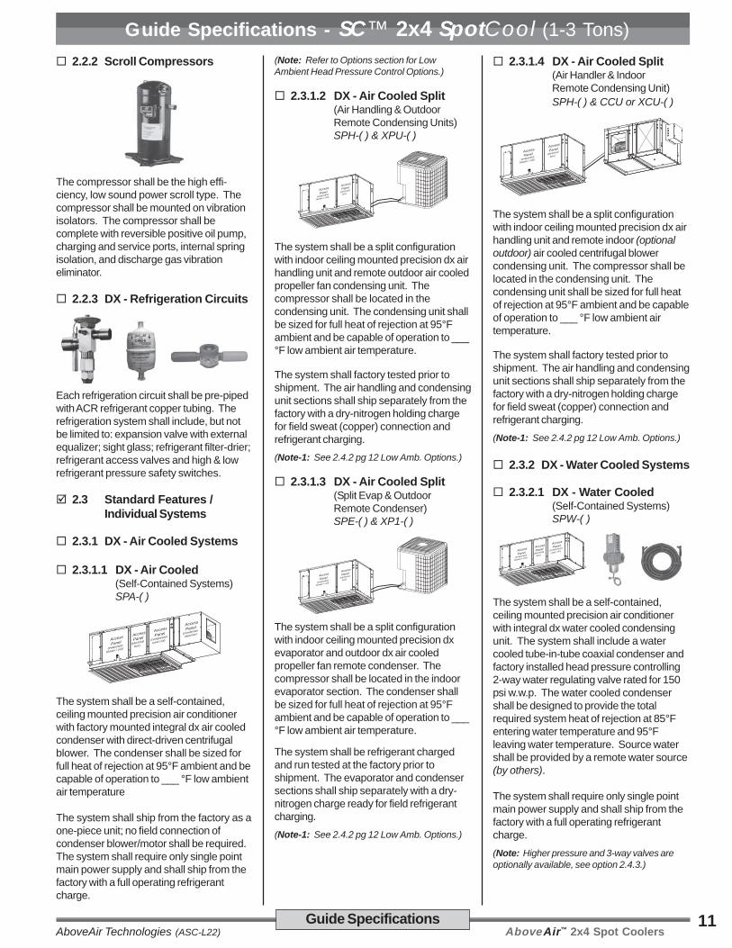
Guide Specifications - SC™ 2x4 SpotCool (1-3 Tons) 2.2.2 Scroll Compressors
The compressor shall be the high effi-ciency, low sound power scroll type. Thecompressor shall be mounted on vibrationisolators. The compressor shall becomplete with reversible positive oil pump,charging and service ports, internal springisolation, and discharge gas vibrationeliminator.
2.2.3 DX - Refrigeration Circuits
Each refrigeration circuit shall be pre-pipedwith ACR refrigerant copper tubing. Therefrigeration system shall include, but notbe limited to: expansion valve with externalequalizer; sight glass; refrigerant filter-drier;refrigerant access valves and high & lowrefrigerant pressure safety switches.
2.3 Standard Features /Individual Systems
2.3.1 DX - Air Cooled Systems
2.3.1.1 DX - Air Cooled(Self-Contained Systems)SPA-( )
AccessPanel
(evaporator
blower / coil)
AccessPanel
(condenser
blwr/mtr)AccessPanel
(electrical
box)
AccessPanel
(compressor,
cond coil)
The system shall be a self-contained,ceiling mounted precision air conditionerwith factory mounted integral dx air cooledcondenser with direct-driven centrifugalblower. The condenser shall be sized forfull heat of rejection at 95°F ambient and becapable of operation to ___ °F low ambientair temperature
The system shall ship from the factory as aone-piece unit; no field connection ofcondenser blower/motor shall be required.The system shall require only single pointmain power supply and shall ship from thefactory with a full operating refrigerantcharge.
(Note: Refer to Options section for LowAmbient Head Pressure Control Options.)
2.3.1.2 DX - Air Cooled Split(Air Handling & OutdoorRemote Condensing Units)SPH-( ) & XPU-( )
AccessPanel
(evaporator
blower / coil)
AccessPanel
(electrical
box)
The system shall be a split configurationwith indoor ceiling mounted precision dx airhandling unit and remote outdoor air cooledpropeller fan condensing unit. Thecompressor shall be located in thecondensing unit. The condensing unit shallbe sized for full heat of rejection at 95°Fambient and be capable of operation to ___°F low ambient air temperature.
The system shall factory tested prior toshipment. The air handling and condensingunit sections shall ship separately from thefactory with a dry-nitrogen holding chargefor field sweat (copper) connection andrefrigerant charging.(Note-1: See 2.4.2 pg 12 Low Amb. Options.)
2.3.1.3 DX - Air Cooled Split(Split Evap & OutdoorRemote Condenser)SPE-( ) & XP1-( )
AccessPanel
(evaporator
blower / coil)
AccessPanel
(electrical
box)
The system shall be a split configurationwith indoor ceiling mounted precision dxevaporator and outdoor dx air cooledpropeller fan remote condenser. Thecompressor shall be located in the indoorevaporator section. The condenser shallbe sized for full heat of rejection at 95°Fambient and be capable of operation to ___°F low ambient air temperature.
The system shall be refrigerant chargedand run tested at the factory prior toshipment. The evaporator and condensersections shall ship separately with a dry-nitrogen charge ready for field refrigerantcharging.(Note-1: See 2.4.2 pg 12 Low Amb. Options.)
2.3.1.4 DX - Air Cooled Split(Air Handler & IndoorRemote Condensing Unit)SPH-( ) & CCU or XCU-( )
AccessPanel
(evaporator
blower / coil)
AccessPanel
(electrical
box)
The system shall be a split configurationwith indoor ceiling mounted precision dx airhandling unit and remote indoor (optionaloutdoor) air cooled centrifugal blowercondensing unit. The compressor shall belocated in the condensing unit. Thecondensing unit shall be sized for full heatof rejection at 95°F ambient and be capableof operation to ___ °F low ambient airtemperature.
The system shall factory tested prior toshipment. The air handling and condensingunit sections shall ship separately from thefactory with a dry-nitrogen holding chargefor field sweat (copper) connection andrefrigerant charging.(Note-1: See 2.4.2 pg 12 Low Amb. Options.)
2.3.2 DX - Water Cooled Systems
2.3.2.1 DX - Water Cooled(Self-Contained Systems)SPW-( )
AccessPanel
(evaporator
blower / coil)
AccessPanel
(electrical
box)
AccessPanel
(compressor,
coax, vlv)
The system shall be a self-contained,ceiling mounted precision air conditionerwith integral dx water cooled condensingunit. The system shall include a watercooled tube-in-tube coaxial condenser andfactory installed head pressure controlling2-way water regulating valve rated for 150psi w.w.p. The water cooled condensershall be designed to provide the totalrequired system heat of rejection at 85°Fentering water temperature and 95°Fleaving water temperature. Source watershall be provided by a remote water source(by others).
The system shall require only single pointmain power supply and shall ship from thefactory with a full operating refrigerantcharge.(Note: Higher pressure and 3-way valves areoptionally available, see option 2.4.3.)

AboveAir™ 2x4 Spot Coolers AboveAir Technologies (ASC-L22)12 Guide Specifications
Guide Specifications - SC™ 2x4 SpotCool (1-3 Tons) 2.3.3 DX - Glycol Cooled Systems
2.3.3.1 DX - Glycol Cooled(Self-Contained Systems)SPG-( )
AccessPanel
(evaporator
blower / coil)
AccessPanel
(electrical
box)
AccessPanel
(compressor,
coax, vlv)
The system shall be a self-contained,ceiling mounted precsion air conditionerwith integral dx glycol cooled condensingunit. The system shall include a glycolcooled tube-in-tube coaxial condenser andfactory installed head pressure controlling2-way glycol regulating valve rated for 150psi w.w.p. The condenser shall bedesigned to provide the total requiredsystem heat of rejection at 110°F enteringglycol temperature and 120°F leaving glycoltemperature based on 40% ethylene glycolsolution. Source glycol shall be provided bya remote glycol drycooler source (seeAboveAir Technologies’ FluidCool™drycoolers).
The system shall require only single pointmain power supply and shall ship from thefactory with a full operating refrigerantcharge.(Note: Higher pressure and 3-way valves areoptionally available, see option 2.4.3.)
2.3.3.2 Glycol Pump Packages& DrycoolersFC_-( ) / PA_-( )
Glycol condenser source shall be providedby a FluidCool™ brand remote air cooledglycol drycooler and Pump-All™ brandpump package.
The glycol drycooler shall be the outdoormounted propeller fan type complete withfactory installed aquastat fan cyclingcontrols, motor starters with overloadprotection and non-fused disconnectswitch.
The glycol pump package shall be a (singleor dual) pump package designed foroutdoor installation complete with individualpump motor starters. Dual glycol pumppackages shall be provided with manuallead-lag switch and field installed flowswitch for automatic switchover to backuppump upon loss of flow.
An expansion tank and air purge fitting valveshall be factory provided for field installa-tion.
The drycooler shall provide __________BTUH total heat rejection at a flow rate of_____ GPM with ____ °F EGT and ____°F LGT at ____ °F ambient air tempera-ture. Each pump shall be ____ Hp andshall be sized to provide ____ GPM @____ Ft. w.g. total system head. The glycolsolution shall be ___ % (ethylene orpropylene) by volume.
The drycooler and pump package shall bedesigned for _____ Volt, ______ Phase,_____ Hertz main power supply.(Note: See AboveAir Technologies’ Fluid-Cool™indoor & outdoor glycol drycooler and PumpAll™glycol pump packages engineering manuals formore information.)
2.3.4 Chilled Water SystemsSPC-( )
AccessPanel
(evaporator
blower / coil)
AccessPanel
(electrical
box)
The system shall be a chilled waterprecision air handling unit with chilled watercooling coil and chilled water control valve.
The chilled water cooling coil shall beconstructed of copper tubes and aluminumfins. Coil end-plates shall be hot dippedgalvanized. The cooling coil shall bemounted in an insulated stainless steelcondensate drain pan.
Chilled water flow shall be controlled by afactory installed slowly opening and closing2-way motorized valve rated for a maxi-mum 300 psig w.w.p.(Note: 3-way and higher pressure valves areoptionally available.)
2.4 Options
2.4.1 Ducted EvaporatorSupply & Return
Access
Panel(evaporator
blower / coil)
EvaporatorSupply Air Outlet
EvaporatorReturn Air Inlet
The system shall be provided with flangedconnections for field ducting of evaporatorreturn air inlet and supply air discharge.The filter(s) shall be 1 inch thick and ratedfor 20% dust spot efficiency (based onASHRAE 52.1). The filter shall be service-
able via side access and without shuttingdown the unit.
2.4.2 Air Cooled Condenser -Low Ambient Control
2.4.2.1 0°F Ambient -Fan Cycling(CCX, XP1 & XPU Models)
Fan cycling controls shall be factoryinstalled to the direct drive condenser fan toallow for low ambient operation to 0°F.
2.4.2.2 -20°F Ambient -Variable Speed Fan(XCU, XP1 & XPU Models)
Variable fan speed head pressure controls(JCI P266 or VFD66) shall be factoryinstalled to allow for low ambient operationto -20°F. Compressor cold start time delayrelay and crankcase heater shall be factoryinstalled with the -20°F low ambient controlfeature.
2.4.2.3 -30°F FloodedCondenser(All Condensing/er Models)
A flooded condenser system shall beprovided to allow for low ambient con-denser operation to -30°F. The floodedsystem shall include a factory installedliquid refrigerant receiver and modulatinghead pressure control valve. Compressorcold start time delay relay and crankcaseheater shall be factory installed with the -30°F low ambient control feature.
2.4.3 DX - Water/GlycolCooled Reg. Valves
2.4.3.12-Way, 150 psig Reg. Valve 2.4.3.23-Way, 150 psig Reg. Valve 2.4.3.32-Way, 350 psig Reg. Valve
2.4.3.43-Way, 350 psig Reg. Valve
System head pressure shall be controlledby a factory provided ____ -way water /glycol regulating valve rated for ____ psigw.w.p.(Note: 3-way valves shall be field installed.)
2.4.4 CONTROL OPTIONS
2.4.4.1 DT-201™ -Digital H/C Thermostat(7-day programmable)

AboveAir™ 2x4 Spot CoolersAboveAir Technologies (ASC-L22)13Guide Specifications
Guide Specifications - SC™ 2x4 SpotCool (1-3 Tons)
A remote wall mounted deluxe 7-dayprogrammable heat pump ready thermo-stat with digital display shall be factoryprovided for field installation. The thermo-stat shall include FAN AUTO-ON, AUTO-COOL-OFF-HEAT-EM (emergency heat),SET and PROG/MAN selector switches.
2.4.4.2 MC-1000™ - Micro T/HController with Alarms
The system shall be provided with a MC-1000™ microprocessor based Tempera-ture and Humidity controller with Alarms.Centered in the controller shall be a graphicLCD display with characters to show theoperating mode, time, set points and actualreadings. The temperature and humiditysensors shall be internal to the remotedisplay. The controller shall be capable ofthree different set points: normal, temporaryand night per day, 7 days per week.
The controller shall include the followingvisual and audible alarm indications (ifapplicable):
• High and Low Temperature• High and Low Humidity• Sensor Failure• Common Alarm Failure• Dirty Filter (optional)• Loss of Airflow (optional)
The controller shall include the followingsystem operations (if applicable):
• Fan - continuous or on demand• Auto-restart upon power loss• Remote stop/start connection• Short cycle protection• Cold start time delay• Heat pump operation with aux. heat
2.4.4.3 MC-2000™, AdvancedMicroprocessor T/HController w/ Alarms
The system shall be provided with a MC-2000™ advanced microprocessor based
temperature and humidity controller withalarms.
Select Features/Benefits:• 4x20 Character Liquid Crystal
Alpha-numerical Display• User Configurable• Run-Time Hours• Current Unit Mode Status• Alarm Status• Digital & Analog Inputs / Outputs• Temperature Anticipation• Remote Stop / Start Contact• Summary Alarm Contact• Automatic or Manual (selectable)
Restart After Power Loss• Sequential Load After Restart• Recovery Delay• Compressor Short Cycle Timers• Cold Start Time Delay• Security Password Access• Self-Diagnostics• Service Mode
Unit Status DisplayThe control system shall display currentunit functions and room status (ifapplicable):
• Current Dry Bulb Temp Set Point• Current Relative Humidity Set Point• System ON/OFF• Cooling• Heating• Humidifying• Dehumidifying• Reheating• Actual Room DB Temperature• Actual Room Relative Humidity
Alarm Conditions:Alarm conditions activate an audible andvisual indicator plus close a summaryalarm dry contact connection. The controlsystem shall alert to the following alarmconditions (if applicable):
• High Temperature • High Head Press• Low Temperature • Smoke Detection• High Humidity • Firestat• Low Humidity • Leak Detection• Sensor Failure • Sensor Failure• Summary Failure • Loss of Power
• Loss of Air Flow• Dirty Filter
Digital & Analog Control Inputs /Outputs:The control system shall be capable of bothdigital (ON/OFF) and analog (proportionalintegral, PI) input and output control.
Select MC-2000 Options: Multi-Unit N+1 Sequencing
BMS Communications Interface:
ModBus RS485 Serial Connection BACnet over MS/TP (RS485 Serial) BACnet Over IP (Ethernet / EIA485) LonWorks FTT10 (RS485 Serial)
2.4.5 HEAT / REHEAT OPTIONS
2.4.5.1 Electric Reheat/Heat
An electric heating system shall be factoryinstalled to provide:
Electric Heat Only during heat mode
Electric Reheat to offset sensiblecooling during the dehumidifica-tion mode and to provide heatingduring heat mode.
Heater elements shall be the low-wattdensity finned-tubular type. The heatershall be complete with individual heaterstage starter/contactor and overheatsafeties. Systems incorporating factoryinstalled electric heaters shall require onlysingle point power to the main unit powerdistribution. The electric heat shall have acapacity of _________ BTU/H and a KWrating of ___ KW, controlled in ___ stages.
2.4.5.1.1 SCR Fired Heat/Reheat(Requires MC-2000™)
The electric heat/reheat shall be controlledthrough a “zero firing” silicon controlrectifier (SCR) with an extruded aluminumheat sink and solid state logic system toprovide close dry bulb temperature controlof the leaving conditioned air temperature.The electric heat shall have a capacity of_________ BTUH and a KW rating of ___KW.
2.4.5.2 Hot Gas ReheatThe system shall be provided with a hotgas reheat coil with 3-way heat reclaimcontrol valve and liquid refrigerant storagereceiver. The hot gas reheat coil shall besized to provide free-energy space neutralleaving air temperature by offsetting thesensible cooling during dx compressoroperation.(Note: Hot Gas Reheat is not available onsystems with compressor located in remotecondensing unit section.)
2.4.5.3 Hot Water Heat
A Hot Water Heating system shall befactory provided. The hot water heating

AboveAir™ 2x4 Spot Coolers AboveAir Technologies (ASC-L22)14 Guide Specifications
Guide Specifications - SC™ 2x4 SpotCool (1-3 Tons)system shall be complete a factoryinstalled aluminum fin, copper tube hotwater coil and field installed 2-way motor-ized hot water control valve. Hot watershall be provided by a remote source at thespecified flow rate and temperature. Thehot water heating system shall have a ratedcapacity of _________ BTUH @ ______GPM, _____°F EWT.
2.4.5.4 Steam HeatA Steam Heating system shall be factoryprovided. The steam heating system shallbe complete a factory installed aluminumfin, copper tube steam coil and fieldinstalled 2-way motorized steam ratedcontrol valve. Steam piping specialtiesshall be field provided. Steam shall beprovided by a remote source at thespecified temperature and pressure. Thesteam heating system shall have a ratedcapacity of _________ BTUH @ ____ psigsaturated steam.
2.4.6 Steam Humidification
An electrode steam canister type humidifi-cation system shall be factory installedwithin the air conditioning system. Thehumidifier shall be complete with dispos-able canister, steam distributor, fill and drainvalve, air gap, automatic flush cycle,manual humidity output adjustment andfield installed remote wall mountedhumidistat. The humidifier shall have amaximum output capacity of ______ lbs/hr.(Note: Remote wall mounted humidistat is notrequired with MC-1000™ or MC-2000™combination temp & humid control option.)
2.5 Accessories
2.5.1 Condensate Pump
A condensate pump shall be factoryprovided for field installation. The conden-sate pump shall be provided with dualinternal float switches: one for pumpoperation initiation and the other for pumpreservoir overflow safety.
2.5.2 Hot Gas Bypass Systems
2.5.2.1 Hot Gas Bypass ToEvaporator Inlet
Each refrigerant circuit shall be providedwith a factory installed hot gas (discharge)bypass valve. The hot gas bypass valveshall be designed to supply hot gas toevaporator inlet as required to provide coilfreeze-protection and capacity modulationunder low load conditions.
2.5.2.2 Hot Gas Bypass ToSuction Line withQuench Valve(SPH/XPU-CCU/CWU-CGURemote Condensing Units3rd Line Not Required!)
Each refrigerant circuit of the Split DXsystem shall be provided with a factoryinstalled hot gas bypass system to include:hot gas (discharge) bypass;desuperheating quench; and hot gas &quench solenoid valves. The hot gasbypass system shall be designed to supplyhot gas and liquid refrigerant to the suctionline as required to provide coil freeze-protection and capacity modulation underlow load conditions. All hot gas bypasscomponents shall be factory installed andshall not require additional field refrigerantlines on split DX systems.
2.5.3 Suction-Line AccumulatorEach refrigerant circuit shall be providedwith a factory installed Suction-LineAccumulator to prevent liquid slugging ofthe compressor and excessive refrigerantdilution of the compressor oil during lowload conditions. The accumulator shallreturn refrigerant and oil to the compressorat a sufficient rate to maintain both systemoperating efficiency and proper oil level.The accumulators shall be wrapped with a1/2” closed-cell neoprene insulation toprevent sweating.
2.5.4 Main Power, Non-FusedDisconnect
A main power non-fused disconnect shallbe factory provided for field installation. Thedisconnect shall be NEMA rated for indooror outdoor installation as required.
2.5.5 Firestat(Factory Installed)
A Firestat shall be factory installed in thereturn air stream of the unit and wired to theA/C unit electrical control panel. TheFirestat shall shut-down all A/C systemoperations upon sensing a high return airtemperature condition.
2.5.6 Smoke Detector(Factory Installed)
A Smoke Detector shall be factory installedin the return air stream of the unit and wiredto the A/C unit electrical control panel. TheSmoke Detector shall shut-down all A/Csystem operations upon activation.
2.5.7 Remote Water-LeakDetector
A remote water-leak detector shall befactory provided for field installation. Theremote water-leak detector shall be wiredto shut down all A/C unit water producingfunctions upon sensing a water leak.
2.5.8 Hanging Spring VibrationIsolators
Each horizontal ceiling mounted sectionshall be provided with spring vibrationhanging isolators sized for the totaldistributive weight of the unit.
2.5.9 Compressor Acoustic /Sound Jacket
Each compressor shall be provided with afactory installed compressor sound jacketwith snap closure system for ease ofremoval and reinstallation. Sound jacketsshall have a noise reduction coefficient(NRC) of 85 per ASTM and C-423 and asound transmission lost (STC) of 11 perASTM E-90.
AboveAir™ 2x4 Spot CoolersAboveAir Technologies (ASC-L22)15Dimensional Data
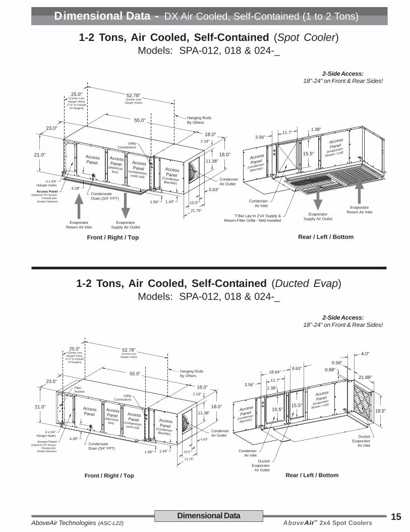
Dimensional Data - DX Air Cooled, Self-Contained (1 to 2 Tons)
1-2 Tons, Air Cooled, Self-Contained (Spot Cooler)Models: SPA-012, 018 & 024-_
1-2 Tons, Air Cooled, Self-Contained (Ducted Evap)Models: SPA-012, 018 & 024-_
21.0"
23.0"55.0"
18.0"
18.0"11.38"
2.19"
10.5"
21.75"
5.63"
25.0"(Center-Line
Hanger Holes;27.0" to Outside
of Hangers)
52.78"(Center-Line
Hanger Holes)
Hanging RodsBy Others
4 x 3/4"Hanger Holes
CondensateDrain (3/4" FPT)
CondenserAir Outlet
Front / Right / Top Rear / Left / Bottom
EvaporatorSupply Air Outlet
EvaporatorReturn Air Inlet
UtilityConnections
AccessPanel
AccessPanel
(electricalbox)
AccessPanel(compressor,cond coil)
AccessPanel(Condenser Blwr/Mtr)
CondenserAir Inlet
15.5"
T-Bar Lay-In 2'x4' Supply &Return-Filter Grille - field installed
11.7"3.56"
1.38"
AccessPanel
(condenser
blwr/mtr)
AccessPanel
(evaporator
blower / coil)
Access Panel(Optional T/H Sensor,
Firestat &/or Smoke Detector)
4.28"
1.44"Evaporator
Return Air InletEvaporatorSupply Air Outlet
1.56"
2-Side Access:18”-24” on Front & Rear Sides!
2-Side Access:18”-24” on Front & Rear Sides!
Rear / Left / Bottom
CondenserAir Inlet
15.5"
DuctedEvaporator
Air Outlet
11.7"3.56"
1.38"
AccessPanel
(condenser
blwr/mtr)
AccessPanel
(evaporator
blower / coil)21.0"
23.0"55.0"
18.0"
18.0"11.38"
2.19"
10.5"
21.75"
5.63"
25.0"(Center-Line
Hanger Holes;27.0" to Outside
of Hangers)
52.78"(Center-Line
Hanger Holes)
Hanging RodsBy Others
4 x 3/4"Hanger Holes
CondensateDrain (3/4" FPT)
CondenserAir Outlet
Front / Right / Top
UtilityConnections
AccessPanel
AccessPanel
(electricalbox)
AccessPanel(compressor,cond coil)
AccessPanel(Condenser Blwr/Mtr)
Access Panel(Optional T/H Sensor,
Firestat &/or Smoke Detector)
4.28"
1.44"1.56"
15.5"
FilterAccess
DuctedEvaporator
Air Inlet
18.64"8.63"
21.88"
18.5"
0.56"0.88"
4.0"

AboveAir™ 2x4 Spot Coolers AboveAir Technologies (ASC-L22)16 Dimensional Data
Dimensional Data - DX Air Cooled, Self-Contained (2.5 Tons)
2.5 Tons, Air Cooled, Self-Contained (Spot Cooler)Models: SPA-030-_
2.5 Tons, Air Cooled, Self-Contained (Ducted Evap)Models: SPA-030-_
25.0"
25.0"55.0"
18.0"
22.0"11.38"
4.19"
10.5"
24.75"
7.13"
27.0"(Center-Line
Hanger Holes;29.0" to Outside
of Hangers)
52.78"(Center-Line
Hanger Holes)
Hanging RodsBy Others
4 x 3/4"Hanger Holes
CondensateDrain (3/4" FPT)
CondenserAir Outlet
Front / Right / Top Rear / Left / Bottom
EvaporatorSupply Air Outlet
EvaporatorReturn Air Inlet
UtilityConnections
AccessPanel
AccessPanel
(electricalbox)
AccessPanel(compressor,cond coil)
AccessPanel(Condenser Blwr/Mtr)
CondenserAir Inlet
19.6"
T-Bar Lay-In 2'x4' Supply &Return-Filter Grille - field installed
11.7"3.56"
1.38"
Access
Panel (condenser
blwr/mtr)
AccessPanel
(evaporator
blower / coil)
Access Panel(Optional T/H Sensor,
Firestat &/or Smoke Detector)
4.19"
1.44"Evaporator
Return Air InletEvaporatorSupply Air Outlet
1.56"
2-Side Access:18”-24” on Front & Rear Sides!
2-Side Access:18”-24” on Front & Rear Sides!
Rear / Left / Bottom
CondenserAir Inlet
19.6"
DuctedEvaporator
Air Outlet
11.7"3.56"
1.38"
Access
Panel (condenser
blwr/mtr)
AccessPanel
(evaporator
blower / coil)25.0"
25.0"55.0"
18.0"
22.0"11.38"
4.19"
10.5"
24.75"
7.13"
27.0"(Center-Line
Hanger Holes;29.0" to Outside
of Hangers)
52.78"(Center-Line
Hanger Holes)
Hanging RodsBy Others
4 x 3/4"Hanger Holes
CondensateDrain (3/4" FPT)
CondenserAir Outlet
Front / Right / Top
UtilityConnections
AccessPanel
AccessPanel
(electricalbox)
AccessPanel(compressor,cond coil)
AccessPanel(Condenser Blwr/Mtr)
Access Panel(Optional T/H Sensor,
Firestat &/or Smoke Detector)
4.19"
1.44"1.56"
19.6"
FilterAccess
DuctedEvaporator
Air Inlet
18.47"8.85"
23.88"
21.63"
0.56"0.88"
4.0"

AboveAir™ 2x4 Spot CoolersAboveAir Technologies (ASC-L22)17
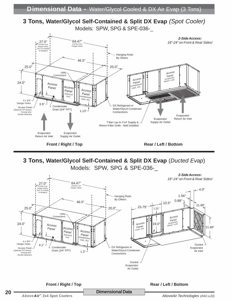
24.0"
25.0"
46.5"
AccessPanel Access
Panel (electrical
box)
AccessPanel (compressor, cond coil)
AccessPanel(Condenser Blwr/Mtr)
1.13"
40.0"
22.88"14.0"
3.56"
14.0"
25.0"
5.5"
CondenserAir Outlet
27.0"(Center-Line
Hanger Holes;29.0" to Outside
of Hangers)
64.47"(Center-Line
Hanger Holes)
Hanging RodsBy Others
20.19"(Center-Line
Hanger Holes)
6 x 3/4"Hanger Holes
Access Panel(Optional T/H Sensor,
Firestat &/or Smoke Detector)
CondensateDrain (3/4" FPT)
3.9"
Front / Right / Top
EvaporatorSupply Air Outlet
EvaporatorReturn Air Inlet
Rear / Left / Bottom
CondenserAir Inlet
T-Bar Lay-In 2'x4' Supply &Return-Filter Grille - field installed
Access
Panel (condenser
blwr/mtr)
Access
Panel(evaporator
blower / coil)
EvaporatorReturn Air InletEvaporator
Supply Air Outlet
UtilityConnections
19.0"
12.88"23.75"
1.31"
Dimensional Data
Dimensional Data - DX Air Cooled, Self-Contained (3 Tons)
3 Tons, Air Cooled, Self-Contained (Spot Cooler)Models: SPA-036-_
3 Tons, Air Cooled, Self-Contained (Ducted Evap)Models: SPA-036-_
Rear / Left / Bottom
Access
Panel (condenser
blwr/mtr)
Access
Panel(evaporator
blower / coil)24.0"
25.0"
46.5"
AccessPanel Access
Panel (electrical
box)
AccessPanel (compressor, cond coil)
AccessPanel(Condenser Blwr/Mtr)
1.3"
40.0"
22.88"14.0"
3.56"
14.0"
25.0"
5.5"
CondenserAir Outlet
6 x 3/4"Hanger Holes
Access Panel(Optional T/H Sensor,
Firestat &/or Smoke Detector)
CondensateDrain (3/4" FPT)
4.1"
Front / Right / Top
27.0"(Center-Line
Hanger Holes;29.0" to Outside
of Hangers)
64.47"(Center-Line
Hanger Holes)
Hanging RodsBy Others
20.19"(Center-Line
Hanger Holes)
UtilityConnections
FilterAccess
19.0"
12.88"
43.94"
1.31"
19.0"
CondenserAir Inlet
DuctedEvaporator
Air Outlet
10.5"
DuctedEvaporator
Air Inlet
21.88"
1.56"
0.88"
21.88"
23.75"
4.0"
2-Side Access:18”-24” on Front & Rear Sides!
2-Side Access:18”-24” on Front & Rear Sides!
AboveAir™ 2x4 Spot Coolers AboveAir Technologies (ASC-L22)18 Dimensional Data
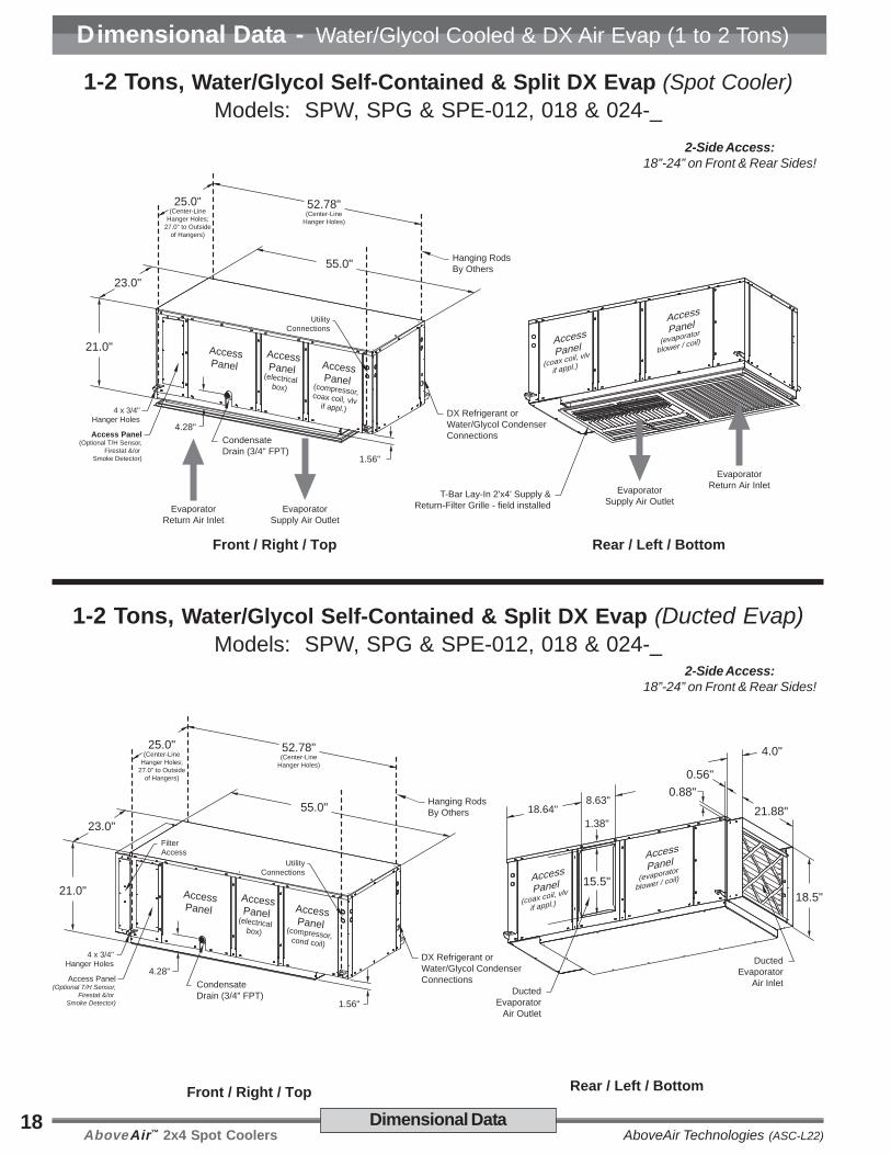
Dimensional Data - Water/Glycol Cooled & DX Air Evap (1 to 2 Tons)
1-2 Tons, Water/Glycol Self-Contained & Split DX Evap (Spot Cooler)Models: SPW, SPG & SPE-012, 018 & 024-_
1-2 Tons, Water/Glycol Self-Contained & Split DX Evap (Ducted Evap)Models: SPW, SPG & SPE-012, 018 & 024-_
Rear / Left / Bottom
T-Bar Lay-In 2'x4' Supply &Return-Filter Grille - field installed
AccessPanel
(evaporator
blower / coil)21.0"
23.0"55.0"
25.0"(Center-Line
Hanger Holes;27.0" to Outside
of Hangers)
52.78"(Center-Line
Hanger Holes)
Hanging RodsBy Others
4 x 3/4"Hanger Holes
CondensateDrain (3/4" FPT)
Front / Right / Top
EvaporatorSupply Air Outlet
EvaporatorReturn Air Inlet
UtilityConnections
AccessPanel
AccessPanel
(electricalbox)
Access Panel(Optional T/H Sensor,
Firestat &/or Smoke Detector)
4.28"
1.56"
DX Refrigerant orWater/Glycol CondenserConnections
EvaporatorReturn Air InletEvaporator
Supply Air Outlet
AccessPanel(compressor,coax coil, vlvif appl.)
AccessPanel
(coax coil, vlv
if appl.)
2-Side Access:18”-24” on Front & Rear Sides!
2-Side Access:18”-24” on Front & Rear Sides!
21.0"
23.0"55.0"
25.0"(Center-Line
Hanger Holes;27.0" to Outside
of Hangers)
52.78"(Center-Line
Hanger Holes)
Hanging RodsBy Others
4 x 3/4"Hanger Holes
CondensateDrain (3/4" FPT)
Front / Right / Top
UtilityConnections
AccessPanel
AccessPanel
(electricalbox)
AccessPanel(compressor,cond coil)
Access Panel(Optional T/H Sensor,
Firestat &/or Smoke Detector)
4.28"
1.56"
FilterAccess
Rear / Left / Bottom
DuctedEvaporator
Air Outlet
1.38"
15.5"
21.88"
18.5"
DuctedEvaporator
Air Inlet
18.64"8.63"
0.56"0.88"
DX Refrigerant orWater/Glycol CondenserConnections
4.0"
AccessPanel
(evaporator
blower / coil)AccessPanel
(coax coil, vlv
if appl.)

AboveAir™ 2x4 Spot CoolersAboveAir Technologies (ASC-L22)19
Dimensional Data - Water/Glycol Cooled & DX Air Evap (2.5 Tons)
Dimensional Data
2.5 Tons, Water/Glycol Self-Contained & Split DX Evap (Spot Cooler)Models: SPW, SPG & SPE-030-_
2.5 Tons, Water/Glycol Self-Contained & Split DX Evap (Ducted Evap)Models: SPW, SPG & SPE-030-_
Rear / Left / Bottom
T-Bar Lay-In 2'x4' Supply &Return-Filter Grille - field installed
AccessPanel
(evaporator
blower / coil)25.0"
25.0"55.0"
27.0"(Center-Line
Hanger Holes;29.0" to Outside
of Hangers)
52.78"(Center-Line
Hanger Holes)
Hanging RodsBy Others
4 x 3/4"Hanger Holes
CondensateDrain (3/4" FPT)
Front / Right / Top
EvaporatorSupply Air Outlet
EvaporatorReturn Air Inlet
UtilityConnections
AccessPanel
AccessPanel
(electricalbox)
Access Panel(Optional T/H Sensor,
Firestat &/or Smoke Detector)
4.19"
1.56"
DX Refrigerant orWater/Glycol CondenserConnections
EvaporatorReturn Air InletEvaporator
Supply Air Outlet
AccessPanel(compressor,coax coil, vlv
if appl.)
AccessPanel
(coax coil, vlv
if appl.)
2-Side Access:18”-24” on Front & Rear Sides!
2-Side Access:18”-24” on Front & Rear Sides!
25.0"
25.0"55.0"
27.0"(Center-Line
Hanger Holes;29.0" to Outside
of Hangers)
52.78"(Center-Line
Hanger Holes)
Hanging RodsBy Others
4 x 3/4"Hanger Holes
CondensateDrain (3/4" FPT)
Front / Right / Top
UtilityConnections
AccessPanel
AccessPanel
(electricalbox)
AccessPanel(compressor,cond coil)
Access Panel(Optional T/H Sensor,
Firestat &/or Smoke Detector)
4.19"
1.56"
FilterAccess
Rear / Left / Bottom
DuctedEvaporator
Air Outlet
1.38"
19.6"
23.88"
21.63"
DuctedEvaporator
Air Inlet
18.47"8.85"
0.56"0.88"
DX Refrigerant orWater/Glycol CondenserConnections
4.0"
AccessPanel
(evaporator
blower / coil)AccessPanel
(coax coil, vlv
if appl.)
AboveAir™ 2x4 Spot Coolers AboveAir Technologies (ASC-L22)20
Rear / Left / Bottom
T-Bar Lay-In 2'x4' Supply &Return-Filter Grille - field installed
Access
Panel (compressor,
coax, vlv)
Access
Panel(evaporator
blower / coil)
EvaporatorReturn Air InletEvaporator
Supply Air Outlet
24.0"
25.0"
46.5"
AccessPanel Access
Panel (electrical
box)
AccessPanel (compressor, coax, vlv)
1.13"
20.0"
27.0"(Center-Line
Hanger Holes;29.0" to Outside
of Hangers)
64.47"(Center-Line
Hanger Holes)
Hanging RodsBy Others
4 x 3/4"Hanger Holes
Access Panel(Optional T/H Sensor,
Firestat &/or Smoke Detector)
CondensateDrain (3/4" FPT)
3.9"
Front / Right / Top
EvaporatorSupply Air Outlet
EvaporatorReturn Air Inlet
UtilityConnections
DX Refrigerant orWater/Glycol CondenserConnections
Dimensional Data - Water/Glycol Cooled & DX Air Evap (3 Tons)
Dimensional Data
3 Tons, Water/Glycol Self-Contained & Split DX Evap (Spot Cooler)Models: SPW, SPG & SPE-036-_
3 Tons, Water/Glycol Self-Contained & Split DX Evap (Ducted Evap)Models: SPW, SPG & SPE-036-_
24.0"
25.0"
46.5"
AccessPanel Access
Panel (electrical
box)
AccessPanel (compressor, coax, vlv)
1.3"
20.0"
27.0"(Center-Line
Hanger Holes;29.0" to Outside
of Hangers)
64.47"(Center-Line
Hanger Holes)
Hanging RodsBy Others
4 x 3/4"Hanger Holes
Access Panel(Optional T/H Sensor,
Firestat &/or Smoke Detector)
CondensateDrain (3/4" FPT)
4.1"
Front / Right / Top
UtilityConnections
DX Refrigerant orWater/Glycol CondenserConnections
Rear / Left / Bottom
Access
Panel (coax, vlv)
Access
Panel(evaporator
blower / coil)19.0"
23.75" 1.31"
DuctedEvaporator
Air Outlet
10.5"
DuctedEvaporator
Air Inlet
21.88"
1.56"0.88"
21.88"
4.0"
2-Side Access:18”-24” on Front & Rear Sides!
2-Side Access:18”-24” on Front & Rear Sides!

AboveAir™ 2x4 Spot CoolersAboveAir Technologies (ASC-L22)21
Dimensional Data - DX Split & Chilled Water Air Handlers (1 to 2 Tons)
Dimensional Data
1-2 Tons, DX Split and Chilled Water, Air Handling Units (Ducted Evap)Models: SPH & SPC-012, 018 & 024-_
21.0"
23.0"55.0"
25.0"(Center-Line
Hanger Holes;27.0" to Outside
of Hangers)
52.78"(Center-Line
Hanger Holes)
Hanging RodsBy Others
4 x 3/4"Hanger Holes
CondensateDrain (3/4" FPT)
Front / Right / Top
UtilityConnections
AccessPanel
AccessPanel
(electricalbox)
AccessPanel(compressor,cond coil)
Access Panel(Optional T/H Sensor,
Firestat &/or Smoke Detector)
4.28"
1.56"
FilterAccess
Rear / Left / Bottom
DuctedEvaporator
Air Outlet
1.38"
AccessPanel
(evaporator coil,
blwr/mtr)15.5"
21.88"
18.5"
DuctedEvaporator
Air Inlet
18.64"8.63"
0.56"0.88"
DX Refrigerant orChilled WaterConnections
4.0"
AccessPanel
(CW Valve)
2-Side Access:18”-24” on Front & Rear Sides!
1-2 Tons, DX Split and Chilled Water, Air Handling Units (Spot Cooler)Models: SPH & SPC-012, 018 & 024-_
Rear / Left / Bottom
T-Bar Lay-In 2'x4' Supply &Return-Filter Grille - field installed
AccessPanel
(evaporator
blower / coil)21.0"
23.0"55.0"
25.0"(Center-Line
Hanger Holes;27.0" to Outside
of Hangers)
52.78"(Center-Line
Hanger Holes)
Hanging RodsBy Others
4 x 3/4"Hanger Holes
CondensateDrain (3/4" FPT)
Front / Right / Top
EvaporatorSupply Air Outlet
EvaporatorReturn Air Inlet
UtilityConnections
AccessPanel
AccessPanel
(electricalbox)
Access Panel(Optional T/H Sensor,
Firestat &/or Smoke Detector)
4.28"
1.56"
DX Refrigerant or Chilled WaterConnections
EvaporatorReturn Air InletEvaporator
Supply Air Outlet
AccessPanel
AccessPanel
2-Side Access:18”-24” on Front & Rear Sides!

AboveAir™ 2x4 Spot Coolers AboveAir Technologies (ASC-L22)22
Dimensional Data - DX Split & Chilled Water Air Handlers (2.5 Tons)
Dimensional Data
2.5 Tons, DX Split and Chilled Water, Air Handling Units (Spot Cooler)Models: SPH & SPC-030-_
2.5 Tons, DX Split and Chilled Water, Air Handling Units (Ducted Evap)Models: SPH & SPC-030-_
Rear / Left / Bottom
T-Bar Lay-In 2'x4' Supply &Return-Filter Grille - field installed
AccessPanel
(evaporator
blower / coil)25.0"
25.0"55.0"
27.0"(Center-Line
Hanger Holes;29.0" to Outside
of Hangers)
52.78"(Center-Line
Hanger Holes)
Hanging RodsBy Others
4 x 3/4"Hanger Holes
CondensateDrain (3/4" FPT)
Front / Right / Top
EvaporatorSupply Air Outlet
EvaporatorReturn Air Inlet
UtilityConnections
AccessPanel
AccessPanel
(electricalbox)
Access Panel(Optional T/H Sensor,
Firestat &/or Smoke Detector)
4.19"
1.56"
DX Refrigerant orChilled WaterConnections
EvaporatorReturn Air InletEvaporator
Supply Air Outlet
AccessPanel(compressor,coax coil, vlv
if appl.)
AccessPanel
(coax coil, vlv
if appl.)
2-Side Access:18”-24” on Front & Rear Sides!
2-Side Access:18”-24” on Front & Rear Sides!
25.0"
25.0"55.0"
27.0"(Center-Line
Hanger Holes;29.0" to Outside
of Hangers)
52.78"(Center-Line
Hanger Holes)
Hanging RodsBy Others
4 x 3/4"Hanger Holes
CondensateDrain (3/4" FPT)
Front / Right / Top
UtilityConnections
AccessPanel
AccessPanel
(electricalbox)
AccessPanel(compressor,cond coil)
Access Panel(Optional T/H Sensor,
Firestat &/or Smoke Detector)
4.19"
1.56"
FilterAccess
Rear / Left / Bottom
DuctedEvaporator
Air Outlet
1.38"
19.6"
23.88"
21.63"
DuctedEvaporator
Air Inlet
18.47"8.85"
0.56"0.88"
DX Refrigerant orChilled WaterConnections
4.0"
AccessPanel
(evaporator
blower / coil)AccessPanel
(coax coil, vlv
if appl.)

AboveAir™ 2x4 Spot CoolersAboveAir Technologies (ASC-L22)23
24.0"
25.0"
46.5"
AccessPanel Access
Panel (electrical
box)
4 x 3/4"Hanger Holes
Access Panel(Optional T/H Sensor,
Firestat &/or Smoke Detector)
CondensateDrain (3/4" FPT)
4.1"
Front / Right / Top
27.0"(Center-Line
Hanger Holes;29.0" to Outside
of Hangers)
44.28"(Center-Line
Hanger Holes)
Hanging RodsBy Others
UtilityConnections
FilterAccess
Rear / Left / Bottom
AccessPanel
(evaporator
blower / coil)19.0"
3.56"1.31"
DuctedEvaporator
Air Outlet
10.5"
DuctedEvaporator
Air Inlet
21.88"
1.56"
0.88"
21.88"
4.0"
DX Refrigerant orChilled WaterConnections
24.0"
25.0"
46.5"
AccessPanel Access
Panel (electrical
box)
27.0"(Center-Line
Hanger Holes;29.0" to Outside
of Hangers)
44.28"(Center-Line
Hanger Holes)
Hanging RodsBy Others
4 x 3/4"Hanger Holes
Access Panel(Optional T/H Sensor,
Firestat &/or Smoke Detector)
CondensateDrain (3/4" FPT)
3.9"
Front / Right / Top
EvaporatorSupply Air Outlet
EvaporatorReturn Air Inlet
UtilityConnections
DX Refrigerant orChilled WaterConnections
Rear / Left / Bottom
T-Bar Lay-In 2'x4'Supply & Return-Filter Grille
- field installed
Access
Panel(evaporator
blower / coil)
EvaporatorReturn Air InletEvaporator
Supply Air Outlet
Dimensional Data - DX Split & Chilled Water Air Handlers (3 Tons)
Dimensional Data
3 Tons, DX Split and Chilled Water, Air Handling Units (Spot Cooler)Models: SPH & SPC-036-_
3 Tons, DX Split and Chilled Water, Air Handling Units (Ducted Evap)Models: SPH & SPC-036-_
2-Side Access:18”-24” on Front & Rear Sides!
2-Side Access:18”-24” on Front & Rear Sides!

AboveAir™ 2x4 Spot Coolers AboveAir Technologies (ASC-L22)24
Dimensional Data - Air Cooled, Remote Condensing Units & Condensers
Dimensional Data
1-3 Tons, Outdoor, DX - Air CooledPropeller Fan, Remote Condensing Units & Condensers
Models: XPU & XP1-012 thru 036
1-3 Tons, Indoor, Remote Centrifugal BlowerDX Air Cooled Condensing Units & Condensers
“Same-Face (standard) or Optional Straight-Thru & “90° L” Air Patterns”Models: CCU & CCX-012 thru 036
REAR / LEFT / TOPFRONT / LEFT / TOP
A
1-1/2" Channel
Main Electric Box
RefrigerantConnections
BC
Rear / Left / Bottom
22.88"
25.0"
AccessPanel (compressor, cond coil)
AccessPanel(Condenser Blwr/Mtr)
40.0"
4 x 3/4"Hanger Holes
Front / Right / Top
27.0"(Center-Line
Hanger Holes;29.0" to Outside
of Hangers)
38.0"(Center-Line
Hanger Holes)
Hanging RodsBy Others
CondenserAir Inlet
12.88"
6.0"14.0"
23.75"
3.0"
14.0"
3.56"
1.31"
19.0"
CondenserAir Outlet
Access
Panel
(Cond
Blwr/Mtr)
Main ElectricBox / Utility
Connections
DX Refrigerant orChilled WaterConnections
Optional CondenserAir Outlet Locations
3-Side Access:18”-24” on Front, Left & Right Sides!
XPU & XP1-( )Model Size
Dimensions
A B C
XPU & XP1-012 & 018 25-5/16" 23-1/8" 23-1/8"
XPU & XP1-024 28-11/16" 23-1/8" 23-1/8"
XPU & XP1-030 31-3/16" 25-3/4" 25-3/4"
XPU & XP1-036 32-5/16" 31-3/16" 31-3/16"

AboveAir™ 2x4 Spot CoolersAboveAir Technologies (ASC-L22)25
Dimensional Data - Remote Water/Glycol Cooled Condensing Units
Dimensional Data
1-3 Tons, Indoor, Remote DX Water/Glycol Cooled Condensing UnitsModels: CWU & CGU-012 thru 036
Rear / Left / Bottom
22.88"
25.0"
AccessPanel (compressor, Coax, Vlv)
20.0"
4 x 3/4"Hanger Holes
Front / Right / Top
27.0"(Center-Line
Hanger Holes;29.0" to Outside
of Hangers)
17.75"(Center-Line
Hanger Holes)
Hanging RodsBy Others
Water/Glycol CooledCondenser Connections
6.0"
Main ElectricBox / Utility Connections
AccessPanel
(compressor,
Coax, Vlv)
3-Side Access:18”-24” on Front, Left & Right Sides!

AboveAir™ 2x4 Spot Coolers AboveAir Technologies (ASC-L22)26 Nomenclature / Ship Wts
Supplemental Data - Notes
Notes:____________________________________________________________________
____________________________________________________________________
____________________________________________________________________
____________________________________________________________________
____________________________________________________________________
____________________________________________________________________
____________________________________________________________________
____________________________________________________________________
____________________________________________________________________
____________________________________________________________________
____________________________________________________________________
____________________________________________________________________
____________________________________________________________________
____________________________________________________________________
____________________________________________________________________
____________________________________________________________________
____________________________________________________________________
____________________________________________________________________
____________________________________________________________________
____________________________________________________________________

AboveAir™ 2x4 Spot CoolersAboveAir Technologies (ASC-L22)27Nomenclature / Ship Wts
Supplemental Data - Model Nomenclature & Unit Weights
Model Nomenclature
Approximate Unit ShipWeights (lbs.)
UNITSIZE
MODEL TYPE
SPA SPH CCU SPE CCX XPU XP1 SPW/G CWU/CGU SPC
012 315 180 195 225 160 110 65 305 125 185
018 335 180 215 245 160 115 70 325 145 185
024 330 180 215 245 160 120 75 325 145 185
030 375 185 220 250 160 145 95 335 150 190
036 410 190 230 290 160 180 120 335 150 195
Packaged Systems & Split Evaporators
SP H - 036 - 3 - E1 Ha b - c - d - e f
a: SP - SpotCool™ 2x4 Horizonal Series
b: A - DX, Air CooledC - Chilled WaterE - DX, Evaporator with CompressorG - DX, Glycol CooledH - DX, Air Handling UnitW - DX, Water Cooled
c: 012 = 1 Ton; 018 = 1.5 Tons; 024 = 2.0 Tons; 030 = 2.5 Tons;036 = 3.0 Tons
d: 1 - 208-230V / 1 Ph / 60 Hz3 - 208-230V / 3 Ph / 60 Hz4 - 460-480V / 3 Ph / 60 Hz5 - 575V / 3 Ph / 60 Hz7 - 277V / 1 Ph / 60 Hz8 - 460-480V / 1 Ph / 60 Hz
e: 00 - No HeatE1 - Electric Heat 1-StageE2 - Electric Heat 2-StagesES - SCR Fired Electric HeatHE - Heat Pump with Auxiliary Electric HeatHG - Hot Gas ReheatHP - Heat Pump w/o Auxiliary Electric HeatHW - Hot Water HeatES - SCR Fired Electric HeatST - Steam Heat
f: 0 - No HumidifierH - Electrode Canister Humidifier
Heat Rejection Systems
C C U - 630 - 3 - 00
a b c - d - e - f
a: C - SpotCool Series Remote Heat Exchanger
b: C - DX, Air Cooled, Indoor Centrifugal Blower TypeG - DX, Glycol CooledP - DX, Air Cooled, Outdoor Propeller Fan TypeW - DX, Water Cooled
c: U - DX Condensing UnitX - DX Condenser
d: 012 = 1 Ton; 018 = 1.5 Tons; 024 = 2.0 Tons; 030 = 2.5 Tons;036 = 3.0 Tons
e: 1 - 208-230V / 1 Ph / 60 Hz3 - 208-230V / 3 Ph / 60 Hz4 - 460-480V / 3 Ph / 60 Hz5 - 575V / 3 Ph / 60 Hz7 - 277V / 1 Ph / 60 Hz8 - 460-480V / 1 Ph / 60 Hz
f: 00 - NoneHP - Heat Pump

AboveAir™ 2x4 Spot Coolers AboveAir Technologies (ASC-L22)28
I n n o v a t i v e H VA C S o l u t i o n s
5179 Mountville RoadFrederick, Maryland 21703, U.S.A.
Phone: 301-874-1130, Facsimile: 301-874-1131
Email: [email protected]
Copyright 10/11Form: ASC-L22
Specifications are subjectto change without notice.
www.aaaaabobobobobovvvvveaireaireaireaireair.com
Comfort - Packaged & SplitVertical Floor Mounted
Air Conditioners(1 to 45 Tons)
VK-MissionCriticalTM - Up-Flow & Down-FlowVertical Floor Mounted Computer Room
Air Conditioners(1 to 30 Tons)
Remote Air CooledCondensers, Condensing Units &
Glycol Drycoolers(1 to 180 Tons of THR)
Precision - Vertical Floor ConsoleMounted Air Conditioners
(1 to 30 Tons)
High-Static BD “Ducted”Ceiling Mounted A/C’s
(1 to 30 Tons)
2x4 “Spot-Cool & Ducted”Ceiling Mounted A/C’s
(1 to 3 Tons)
Single, Dual & TriplexGlycol Pump Packages
(1/2 to 50 HP)
Ceiling Ceiling Ceiling Ceiling Ceiling Air ConditionerAir ConditionerAir ConditionerAir ConditionerAir ConditionersssssSpotSpotSpotSpotSpotCoolCoolCoolCoolCool
™ - 2x4 T-Bar “Spot-Cool & Ducted”Comfort & Precision Ceiling Mounted A/C’s
HKHKHKHKHK ™ HorizHorizHorizHorizHorizontalontalontalontalontal - Hi-Static Ducted Comfort &
Precision Ceiling Mounted A/C’s
HKHKHKHKHK-O-O-O-O-OAAAAA ™ - Horizontal Up to 100% DOAS High-
Percentage Outside Air Ceiling Mounted A/C’s
FFFFFloor loor loor loor loor Air ConditionerAir ConditionerAir ConditionerAir ConditionerAir ConditionersssssMissionMissionMissionMissionMissionCriticalCriticalCriticalCriticalCritical
™ - Precision Vertical FloorMounted Computer Room A/C’s
VKVKVKVKVK™ VVVVVerererererticalticalticalticaltical - SCAV, Vertical Floor MountedSelf-Contained & Split Comfort Constant Air Volumeand Variable Air Volume (VAV) A/C’s & Heat Pumps
VKVKVKVKVK-O-O-O-O-OAAAAA ™ - Vertical Up to 100% DOAS High-
Percentage Outside Air Vertical Floor Mounted A/C’s
VKVKVKVKVK™ ConsoleConsoleConsoleConsoleConsole - Vertical Floor Console MountedSelf-Contained & Split A/C’s & Heat Pumps
RRRRRemote Heaemote Heaemote Heaemote Heaemote Heat Rt Rt Rt Rt Rejectionejectionejectionejectionejection
FluidFluidFluidFluidFluidCoolCoolCoolCoolCool ™ - Indoor & Outdoor Remote Glycol
Drycoolers
PumpPumpPumpPumpPumpAllAllAllAllAll ™ - Single, Dual & Triplex Standard &
Variable (VFD) Speed Glycol Pump Packages