R40 Manual August 2013 - cadmanpower.comcadmanpower.com/pdfs/manuals/R40-Manual-August-2013.pdf ·...
16
Revised August 2013 Serial Number: BRIGGS IRRIGATION Operators Manual & Parts Manual R40 Hosereel Mounted Boom Irrigator Briggs Irrigation Boyle Road CORBY Northamptonshire NN17 5XU Tel: 00 44 (0)1536 260338 Fax: 00 44 (0)1536 263972 [email protected] www.briggsirrigation.co.uk
Transcript of R40 Manual August 2013 - cadmanpower.comcadmanpower.com/pdfs/manuals/R40-Manual-August-2013.pdf ·...

Revised August 2013
Serial Number:
BRIGGS IRRIGATION
Operators Manual
& Parts Manual
R40 Hosereel Mounted
Boom Irrigator
Briggs Irrigation
Boyle Road
CORBY
Northamptonshire
NN17 5XU Tel: 00 44 (0)1536 260338
Fax: 00 44 (0)1536 263972
www.briggsirrigation.co.uk

1
EC DECLARATION OF CONFORMITY
MANUFACTURER Briggs (UK) Limited
Boyle Road
Corby
Northamptonshire
NN17 5XU
England
Tel: + 44 (0) 1536 260338
Fax: + 44 (0) 1536 263972
Email: [email protected]
Web: www.briggsirrigation.co.uk
HOSE REEL BOOM MODEL: R40
This machine complies to BS EN292
Part 2 1991
(89/392/EEC)
Signed on behalf of Briggs (UK) Ltd
…………………………………………
A M Colwill
Director
2
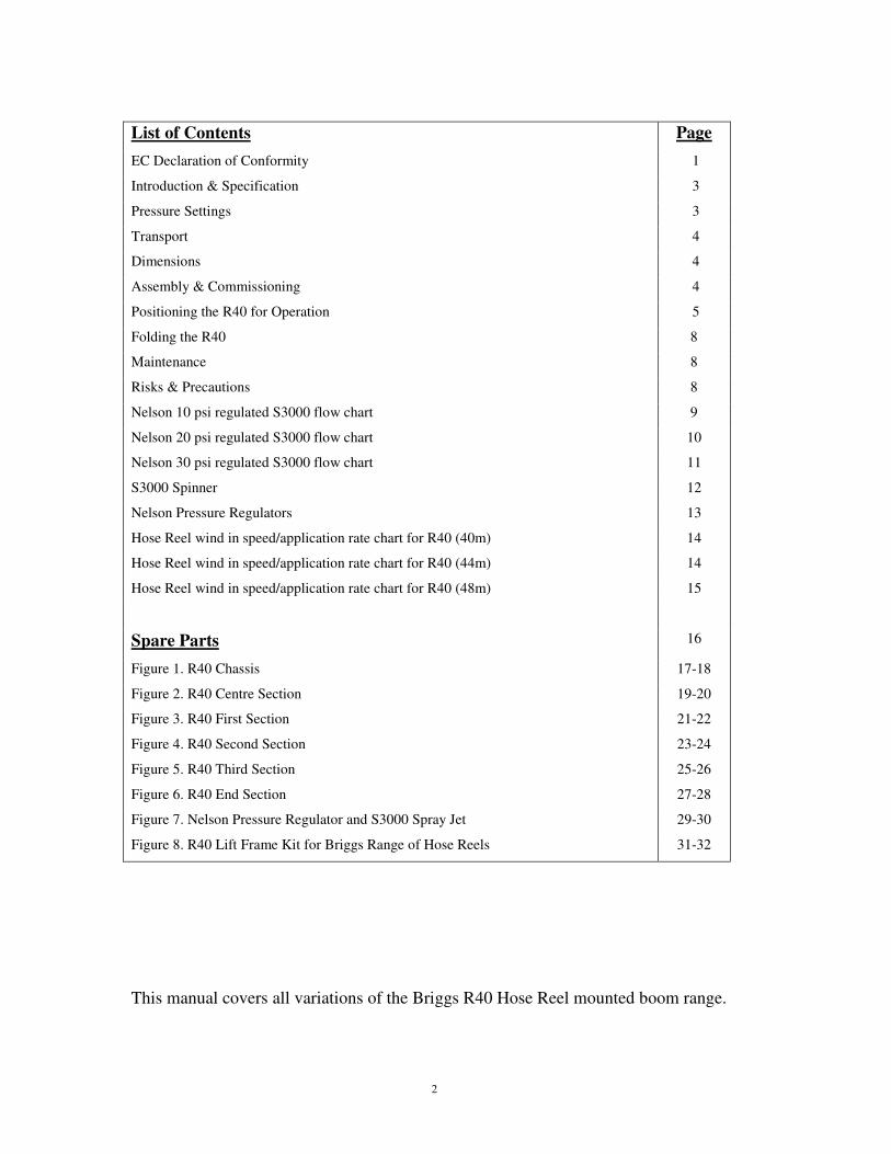
List of Contents Page
EC Declaration of Conformity 1
Introduction & Specification 3
Pressure Settings 3
Transport 4
Dimensions 4
Assembly & Commissioning 4
Positioning the R40 for Operation 5
Folding the R40 8
Maintenance 8
Risks & Precautions 8
Nelson 10 psi regulated S3000 flow chart 9
Nelson 20 psi regulated S3000 flow chart 10
Nelson 30 psi regulated S3000 flow chart 11
S3000 Spinner 12
Nelson Pressure Regulators 13
Hose Reel wind in speed/application rate chart for R40 (40m) 14
Hose Reel wind in speed/application rate chart for R40 (44m) 14
Hose Reel wind in speed/application rate chart for R40 (48m) 15
Spare Parts 16
Figure 1. R40 Chassis 17-18
Figure 2. R40 Centre Section 19-20
Figure 3. R40 First Section 21-22
Figure 4. R40 Second Section 23-24
Figure 5. R40 Third Section 25-26
Figure 6. R40 End Section 27-28
Figure 7. Nelson Pressure Regulator and S3000 Spray Jet 29-30
Figure 8. R40 Lift Frame Kit for Briggs Range of Hose Reels 31-32
This manual covers all variations of the Briggs R40 Hose Reel mounted boom range.
3
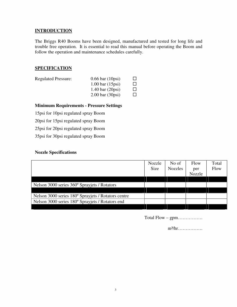
INTRODUCTION
The Briggs R40 Booms have been designed, manufactured and tested for long life and
trouble free operation. It is essential to read this manual before operating the Boom and
follow the operation and maintenance schedules carefully.
SPECIFICATION
Regulated Pressure: 0.66 bar (10psi) �
1.00 bar (15psi) �
1.40 bar (20psi) �
2.00 bar (30psi) �
Minimum Requirements - Pressure Settings
15psi for 10psi regulated spray Boom
20psi for 15psi regulated spray Boom
25psi for 20psi regulated spray Boom
35psi for 30psi regulated spray Boom
Nozzle Specifications
Nozzle
Size
No of
Nozzles
Flow
per
Nozzle
Total
Flow
Nelson 3000 series 360º Sprayjets / Rotators
Nelson 3000 series 180º Sprayjets / Rotators centre
Nelson 3000 series 180º Sprayjets / Rotators end
Total Flow – gpm…………….
m³/hr…………….
4
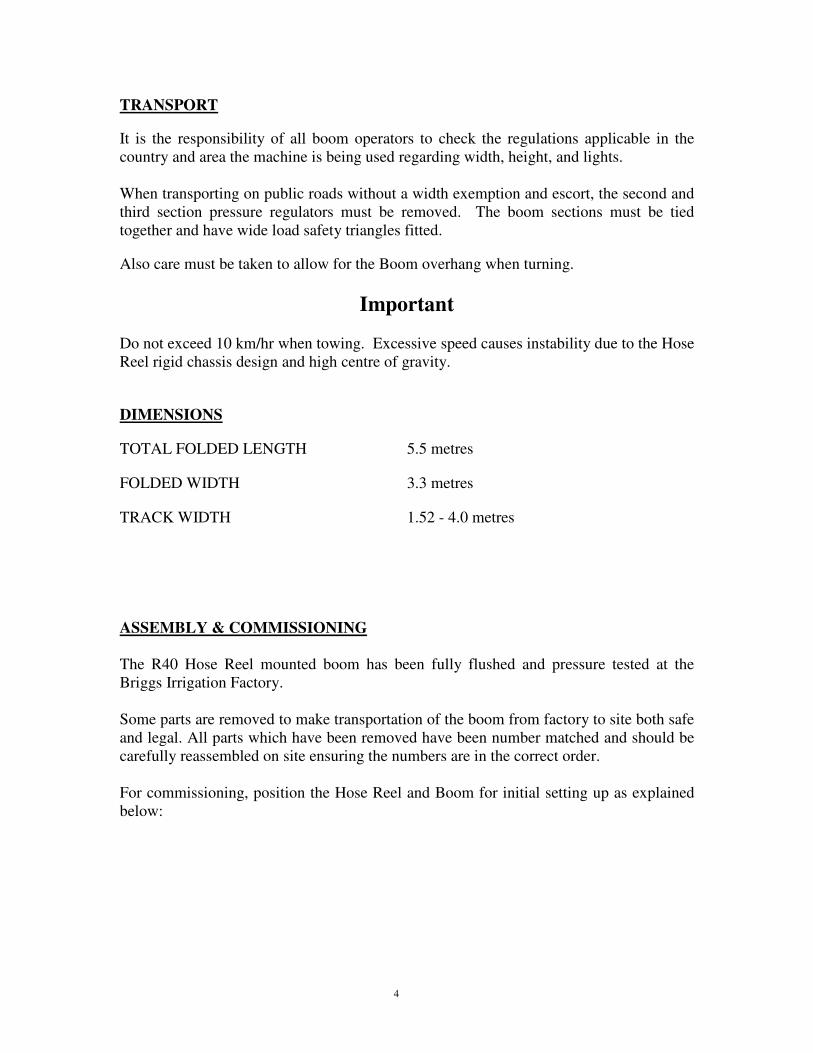
TRANSPORT
It is the responsibility of all boom operators to check the regulations applicable in the
country and area the machine is being used regarding width, height, and lights.
When transporting on public roads without a width exemption and escort, the second and
third section pressure regulators must be removed. The boom sections must be tied
together and have wide load safety triangles fitted.
Also care must be taken to allow for the Boom overhang when turning.
Important Do not exceed 10 km/hr when towing. Excessive speed causes instability due to the Hose
Reel rigid chassis design and high centre of gravity.
DIMENSIONS
TOTAL FOLDED LENGTH 5.5 metres
FOLDED WIDTH 3.3 metres
TRACK WIDTH 1.52 - 4.0 metres
ASSEMBLY & COMMISSIONING
The R40 Hose Reel mounted boom has been fully flushed and pressure tested at the
Briggs Irrigation Factory.
Some parts are removed to make transportation of the boom from factory to site both safe
and legal. All parts which have been removed have been number matched and should be
carefully reassembled on site ensuring the numbers are in the correct order.
For commissioning, position the Hose Reel and Boom for initial setting up as explained
below:
5
POSITIONING THE R40 FOR OPERATION
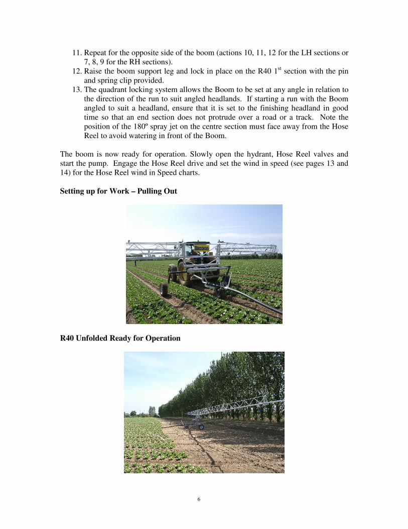
1. Tow the Hose Reel into the position required to start the irrigation run.
2. Turn the hose drum on the turntable (if fitted) to line up with the centre of the
irrigation run (see photograph on page 6).
3. Set the wheel track of the boom. This is done manually by loosening the locking
bolts and sliding the wheel mounting legs out to the desired position. The locking
bolts must be done up tightly to ensure there is no movement during the course of
the run. The wheels can be set to span up to a width of 4m.
4. Lower the boom by operating the Hose Reel hydraulic leg/lift frame system.
5. Set Hose Reel for ‘pull out position’.
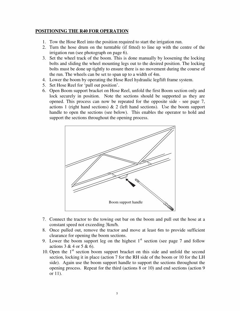
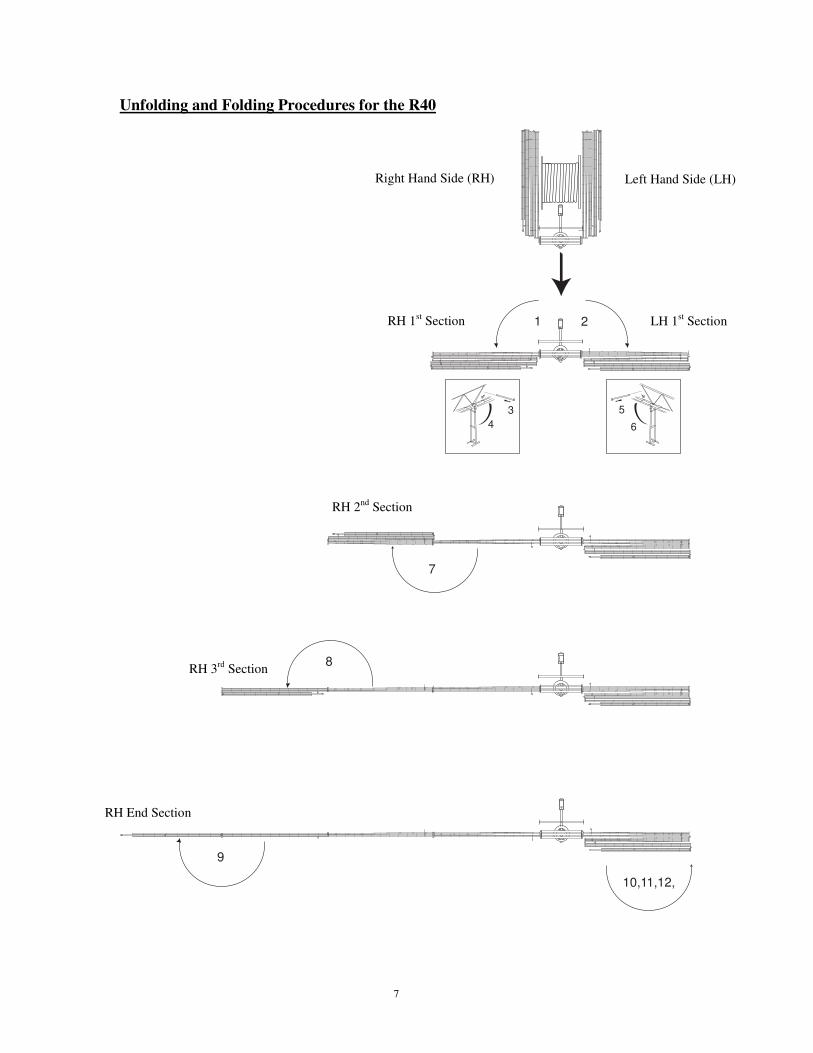
6. Open Boom support bracket on Hose Reel, unfold the first Boom section only and
lock securely in position. Note the sections should be supported as they are
opened. This process can now be repeated for the opposite side - see page 7,
actions 1 (right hand sections) & 2 (left hand sections). Use the boom support
handle to open the sections (see below). This enables the operator to hold and
support the sections throughout the opening process.
7. Connect the tractor to the towing out bar on the boom and pull out the hose at a
constant speed not exceeding 3km/h.
8. Once pulled out, remove the tractor and move at least 6m to provide sufficient
clearance for opening the boom sections.
9. Lower the boom support leg on the highest 1st section (see page 7 and follow
actions 3 & 4 or 5 & 6).
10. Open the 1st section boom support bracket on this side and unfold the second
section, locking it in place (action 7 for the RH side of the boom or 10 for the LH
side). Again use the boom support handle to support the sections throughout the
opening process. Repeat for the third (actions 8 or 10) and end sections (action 9
or 11).
Boom support handle
6
11. Repeat for the opposite side of the boom (actions 10, 11, 12 for the LH sections or
7, 8, 9 for the RH sections).
12. Raise the boom support leg and lock in place on the R40 1st section with the pin
and spring clip provided.
13. The quadrant locking system allows the Boom to be set at any angle in relation to
the direction of the run to suit angled headlands. If starting a run with the Boom
angled to suit a headland, ensure that it is set to the finishing headland in good
time so that an end section does not protrude over a road or a track. Note the
position of the 180º spray jet on the centre section must face away from the Hose
Reel to avoid watering in front of the Boom.
The boom is now ready for operation. Slowly open the hydrant, Hose Reel valves and
start the pump. Engage the Hose Reel drive and set the wind in speed (see pages 13 and
14) for the Hose Reel wind in Speed charts.
Setting up for Work – Pulling Out
R40 Unfolded Ready for Operation
7
Unfolding and Folding Procedures for the R40
8
7
10,11,12,
9
1 2
3
4
5
6
RH 1st Section LH 1
st Section
RH 2nd
Section
RH 3rd
Section
RH End Section
Right Hand Side (RH) Left Hand Side (LH)
8
FOLDING THE R40
1. Lower the boom support legs on both first sections (Page 7, actions 3 to 6)
2. Fold the outer section (end section) on the lower side of the Boom (action 9 for the
Right Hand side or 12 for Left Hand side) into the third section and lock in the boom
support bracket. Note it is important to use the boom support handle to support the
section during the folding operation. Repeat for the third (either 8 or 11) and second
sections (either 7 or 10) on the same side of the boom.
3. Repeat this on the other side of the irrigator (actions 9, 8, 7 for the Right Hand
sections or 12, 11, 10 for the Left).
4. Raise the boom support legs and lock into position on the 1st sections (actions 3 to 6).
5. If necessary, turn the hose drum on the Hose Reel turntable to line up with the centre
of the boom.
6. Fold the first section around the Hose Reel and clamp into the Hose Reel Boom
support bracket (action 2). Repeat for opposite side (action 1)
7. Raise the boom using the hydraulic system on the hosereel.
8. If you are moving to another irrigation run, the boom can be transported at 90 degrees
to the direction of travel. If you are moving to another field you must rotate the drum
so that the hosereel and boom are in the road transport position.
MAINTENANCE
1. Grease the turntable weekly.
2. Grease the rear wheel bearings weekly and repack / adjust annually.
3. Grease the front wheel acetyl bushes weekly on both sides, rotate wheel while
greasing.
4. Grease front wheel steering king pin weekly.
5. Ensure Boom support brackets are holding the Boom centrally. Adjust if necessary.
6. Boom locking joint tension must be checked regularly and is adjusted by slackening
the locking bolt and turning the offset catch cam. Keep regularly greased for ease of
operation.
RISKS AND PRECAUTIONS
• Ensure all locking pins are fully closed on the boom support brackets when
transporting or pulling out the boom.
• Always transport the boom with great caution both on the road and in the field.
• Always secure Booms together with ropes or straps, together with the turntable
pin when moving on public roads.
• Watch out for turning clearance of the Boom section when manoeuvring around
vehicles or any other objects.
• When operating with obstacles in the field (poles etc) ensure the operator is
present to “rotate” the Boom around the obstacle.
• If starting a run with the Boom angled to suit a headland, ensure it is set to the
finishing headland angle in good time so an end section does not protrude over a
road or track.
9
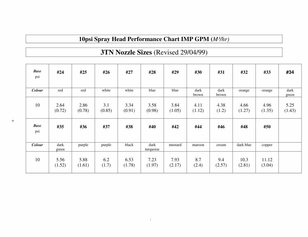
10psi Spray Head Performance Chart IMP GPM (M³/hr)
3TN Nozzle Sizes (Revised 29/04/99)
Base
psi
#24
#25
#26
#27
#28
#29
#30
#31
#32
#33
#34
Colour red red white white blue blue dark
brown
dark
brown
orange orange dark
green
10
2.64
(0.72)
2.86
(0.78)
3.1
(0.85)
3.34
(0.91)
3.58
(0.98)
3.84
(1.05)
4.11
(1.12)
4.38
(1.2)
4.66
(1.27)
4.96
(1.35)
5.25
(1.43)
Base
psi
#35
#36
#37
#38
#40
#42
#44
#46
#48
#50
Colour dark
green
purple purple black dark
turquoise
mustard maroon cream dark blue copper
10
5.56
(1.52)
5.88
(1.61)
6.2
(1.7)
6.53
(1.78)
7.23
(1.97)
7.93
(2.17)
8.7
(2.4)
9.4
(2.57)
10.3
(2.81)
11.12
(3.04)
9

10
20psi Spray Head Performance Chart IMP GPM (M³/hr)
3TN Nozzle Sizes (Revised 29/04/99)
Base
psi
#24
#25
#26
#27
#28
#29
#30
#31
#32
#33
#34
Colour red red white white blue blue dark
brown
dark
brown
orange orange dark
green
20
3.7
(1.01)
4.0
(1.1)
4.4
(1.19)
4.7
(1.28)
5.1
(1.39)
5.4
(1.48)
5.8
(1.59)
6.2
(1.83)
6.6
(1.81)
7.1
(1.93)
7.5
(2.05)
Base
psi
#35
#36
#37
#38
#40
#42
#44
#46
#48
#50
Colour dark
green
purple purple black dark
turquoise
mustard maroon cream dark blue copper
20
7.9
(2.16)
8.3
(2.27)
8.9
(2.42)
9.4
(2.56)
10.4
(2.84)
11.6
(3.15)
12.7
(3.45)
13.9
(3.78)
15.2
(4.13)
16.4
(4.74)
10

11
30 PSi Spray Head Performance Chart IMP GPM (M³/hr)
3TN Nozzle Sizes (Revised 29/04/99)
Base
psi
#24
#25
#26
#27
#28
#29
#30
#31
#32
#33
#34
Colour red red white white blue blue dark
brown
dark
brown
orange orange dark
green
30
4.6
(1.24)
4.9
(1.34)
5.3
(1.46)
5.7
(1.56)
6.2
(1.7)
6.7
(1.82)
7.1
(1.94)
7.6
(2.06)
8.1
(2.22)
8.7
(2.36)
9.2
(2.51)
Base
psi
#35
#36
#37
#38
#40
#42
#44
#46
#48
#50
Colour dark
green
purple purple black dark
turquoise
mustard maroon cream dark blue copper
30
9.7
(2.65)
10.2
(2.78)
10.9
(2.97)
11.5
(3.14)
12.8
(3.49)
14.2
(3.86)
15.5
(4.23)
17.0
(4.63)
18.6
(5.06)
20.1
(5.47)
11
12
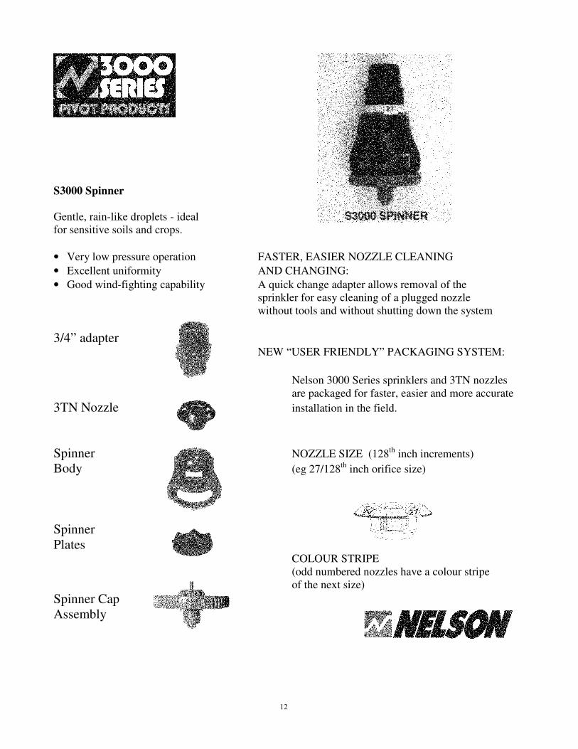
S3000 Spinner
Gentle, rain-like droplets - ideal
for sensitive soils and crops.
• Very low pressure operation FASTER, EASIER NOZZLE CLEANING
• Excellent uniformity AND CHANGING:
• Good wind-fighting capability A quick change adapter allows removal of the
sprinkler for easy cleaning of a plugged nozzle
without tools and without shutting down the system
3/4” adapter NEW “USER FRIENDLY” PACKAGING SYSTEM: Nelson 3000 Series sprinklers and 3TN nozzles are packaged for faster, easier and more accurate
3TN Nozzle installation in the field.
Spinner NOZZLE SIZE (128th
inch increments)
Body (eg 27/128th
inch orifice size)
Spinner
Plates COLOUR STRIPE
(odd numbered nozzles have a colour stripe
of the next size)
Spinner Cap
Assembly

13
FEATURES:
PATENTED DAMPING SYSTEM BLUE TOP The patented O-Ring Dampening System of Colour-Coded Identification
all Nelson Pressure Regulators handles severe
pressure surges, without creating flow Patented Internal
restrictions under working pressures. Dampening System
EXTENDED FLOW RANGE - Retards Vibration
The Nelson Lo-Flo Pressure Regulator extends - Withstands
to 10 gpm, providing economical precision. - Water Hammer
EXTENDED ACCURACY Vented for Below Ground Use
Precision components coupled with an internally
lubricated o-ring minimize frictional drag and Chemically Resistant Materials
hysteresis.
PLUG RESISTANT DESIGN Internally Lubricated O-Ring
An open seat design prevents hair-pinning, for Precision Accuracy
debris hangup and plugging of the pressure
regulator. Plug Resistant Seat Design
PRECISION MANUFACTURED
Made of the toughest chemically resistant
Materials. 100% water tested for accuracy.
Application Notes
Performance Tables. Design Considerations
Contact the Nelson factory for detailed Maintain a 3 psi threshold
Performance information. above the normal spray rated pressure.
Statement of
Expected Performance. CAUTION! Nelson Pressure Regulators are accurate to 6% Pressure regulators should
due to variance of coefficient in manufacturing. be installed downstream
from all shut off valves.
NELSON BLUE TOP PRESSURE REGULATORS Precision Accuracy in tough field environments
HI FLO PSI BAR GPM M³/HR 6 .41 4-16 .91-3.63
10 .70 4-16 .91-3.63
15 1.0 2-20 .45-4.54
20 1.4 2-20 .45-4.54
25 1.7 2-20 .45-4.54
30 2.0 2-20 .45-4.54 40 2.8 2-20 .45-4.54
50 3.4 2-20 .45-4.54
13

14
Hose Reel wind in Speed Charts
for Application rate range.
Chart Showing Wind In Speeds For Required Application Rate (metres per hour)
R40 Boom Water Flow - imperial gpm + m³/hr Lane Spacing – 40m imperial gpm 50 60 70 80 90 100 110 120 130 140 150 160 170 180
M³/hr 14 16 19 22 25 27 30 33 36 38 41 44 47 49
AP
PL
ICA
TIO
N R
AT
E
5 mm 68 82 95 109 123 136 150 164 177 191 205 218 232 245
7.5 mm 45 55 64 73 82 91 100 109 118 127 136 145 155 164
10 mm 34 41 48 55 61 68 75 82 89 95 102 109 116 123
12.5 mm 27 33 38 44 49 55 60 65 71 76 82 87 93 98
15 mm 23 27 32 36 41 45 50 55 59 64 68 73 77 82
17.5 mm 19 23 27 31 35 39 43 47 51 55 58 62 66 70
20 mm 17 20 24 27 31 34 37 41 44 48 51 55 58 61
22.5 mm 15 18 21 24 27 30 33 36 39 42 45 48 52 55
25 mm 14 16 19 22 25 27 30 33 35 38 41 44 46 49
27.5 mm 12 15 17 20 22 25 27 30 32 35 37 40 42 45
30 mm 11 14 16 18 20 23 25 27 30 32 34 36 39 41
32.5 mm 10 13 15 17 19 21 23 25 27 29 31 34 36 38
35 mm 10 12 14 16 18 19 21 23 25 27 29 31 33 35
37.5 mm 9 11 13 15 16 18 20 22 24 25 27 29 31 33
40 mm 9 10 12 14 15 17 19 20 22 24 26 27 29 31
Chart Showing Wind In Speeds For Required Application Rate (metres per hour)
R40 Boom Water Flow - imperial gpm + m³/hr Lane Spacing – 44m imperial gpm 50 60 70 80 90 100 110 120 130 140 150 160 170 180
M³/hr 14 16 19 22 25 27 30 33 36 38 41 44 47 49
AP
PL
ICA
TIO
N R
AT
E
5 mm 62 74 87 99 112 124 136 149 161 174 186 198 211 223
7.5 mm 41 50 58 66 74 83 91 99 107 116 124 132 140 149
10 mm 31 37 43 50 56 62 68 74 81 87 93 99 105 112
12.5 mm 25 30 35 40 45 50 55 59 64 69 74 79 84 89
15 mm 21 25 29 33 37 41 45 50 54 58 62 66 70 74
17.5 mm 18 21 25 28 32 35 39 42 46 50 53 57 60 64
20 mm 15 19 22 25 28 31 34 37 40 43 46 50 53 56
22.5 mm 14 17 19 22 25 28 30 33 36 39 41 44 47 50
25 mm 12 15 17 20 22 25 27 30 32 35 37 40 42 45
27.5 mm 11 14 16 18 20 23 25 27 29 32 34 36 38 41
30 mm 10 12 14 17 19 21 23 25 27 29 31 33 35 37
32.5 mm 10 11 13 15 17 19 21 23 25 27 29 31 32 34
35 mm 9 11 12 14 16 18 19 21 23 25 27 28 30 32
37.5 mm 8 10 12 13 15 17 18 20 21 23 25 26 28 30
40 mm 8 9 11 12 14 15 17 19 20 22 23 25 26 28

15
Hose Reel wind in Speed Charts
for Application rate range. (cont.)
Chart Showing Wind In Speeds For Required Application Rate (metres per hour)
R40 Boom Water Flow - imperial gpm + m³/hr Lane Spacing - 48m imperial gpm 50 60 70 80 90 100 110 120 130 140 150 160 170 180
M³/hr 14 16 19 22 25 27 30 33 36 38 41 44 47 49
AP
PL
ICA
TIO
N R
AT
E
5 mm 57 68 80 91 102 114 125 136 148 159 170 182 193 205
7.5 mm 38 45 53 61 68 76 83 91 98 106 114 121 129 136
10 mm 28 34 40 45 51 57 62 68 74 80 85 91 97 102
12.5 mm 23 27 32 36 41 45 50 55 59 64 68 73 77 82
15 mm 19 23 27 30 34 38 42 45 49 53 57 61 64 68
17.5 mm 16 19 23 26 29 32 36 39 42 45 49 52 55 58
20 mm 14 17 20 23 26 28 31 34 37 40 43 45 48 51
22.5 mm 13 15 18 20 23 25 28 30 33 35 38 40 43 45
25 mm 11 14 16 18 20 23 25 27 30 32 34 36 39 41
27.5 mm 10 12 14 17 19 21 23 25 27 29 31 33 35 37
30 mm 9 11 13 15 17 19 21 23 25 27 28 30 32 34
32.5 mm 9 10 12 14 16 17 19 21 23 24 26 28 30 31
35 mm 8 10 11 13 15 16 18 19 21 23 24 26 28 29
37.5 mm 8 9 11 12 14 15 17 18 20 21 23 24 26 27
40 mm 7 9 10 11 13 14 16 17 18 20 21 23 24 26