R3267 Series OPT67 1xEV-DO(HDR) Measurement Option...
178
MANUAL NUMBER C Printed in Japan ADVANTEST CORPORATION All rights reserved. R3267 Series OPT67 1xEV-DO(HDR) Measurement Option Operation Manual FOE-8440023B00 2001 First printing December 25, 2001 Applicable models R3264 R3267 R3273 Cover
Transcript of R3267 Series OPT67 1xEV-DO(HDR) Measurement Option...

MANUAL NUMBER
CPrinted in Japan
ADVANTEST CORPORATIONAll rights reserved.
R3267 Series OPT67
1xEV-DO(HDR)
Measurement Option
Operation Manual
FOE-8440023B00
2001 First printing December 25, 2001
Applicable modelsR3264R3267R3273
Cover

No. ESF00
Safety Summary
Safety Summary
To ensure thorough understanding of all functions and to ensure efficient use of this instrument, please read themanual carefully before using. Note that Advantest bears absolutely no responsibility for the result of operationscaused due to incorrect or inappropriate use of this instrument.
If the equipment is used in a manner not specified by Advantest, the protection provided by the equipment maybe impaired.
• Warning Labels
Warning labels are applied to Advantest products in locations where specific dangers exist. Paycareful attention to these labels during handling. Do not remove or tear these labels. If you haveany questions regarding warning labels, please ask your nearest Advantest dealer. Our addressand phone number are listed at the end of this manual.
Symbols of those warning labels are shown below together with their meaning.
DANGER: Indicates an imminently hazardous situation which will result in death or seriouspersonal injury.
WARNING: Indicates a potentially hazardous situation which will result in death or seriouspersonal injury.
CAUTION: Indicates a potentially hazardous situation which will result in personal injury ora damage to property including the product.
• Basic Precautions
Please observe the following precautions to prevent fire, burn, electric shock, and personal inju-ry.
• Use a power cable rated for the voltage in question. Be sure however to use a power cableconforming to safety standards of your nation when using a product overseas.
• When inserting the plug into the electrical outlet, first turn the power switch OFF and theninsert the plug as far as it will go.
• When removing the plug from the electrical outlet, first turn the power switch OFF and thenpull it out by gripping the plug. Do not pull on the power cable itself. Make sure your handsare dry at this time.
• Before turning on the power, be sure to check that the supply voltage matches the voltagerequirements of the instrument.
• Be sure to plug the power cable into an electrical outlet which has a safety ground terminal.Grounding will be defeated if you use an extension cord which does not include a safetyground terminal.
• Be sure to use fuses rated for the voltage in question.
• Do not use this instrument with the case open.
• Do not place objects on top of this product. Also, do not place flower pots or other containerscontaining liquid such as chemicals near this product.
Safety-1
Safety Summary
• When the product has ventilation outlets, do not stick or drop metal or easily flammable ob-jects into the ventilation outlets.
• When using the product on a cart, fix it with belts to avoid its drop.
• When connecting the product to peripheral equipment, turn the power off.
• Caution Symbols Used Within this Manual
Symbols indicating items requiring caution which are used in this manual are shown below to-gether with their meaning.
DANGER: Indicates an item where there is a danger of serious personal injury (death or seri-ous injury).
WARNING: Indicates an item relating to personal safety or health.
CAUTION: Indicates an item relating to possible damage to the product or instrument or relat-ing to a restriction on operation.
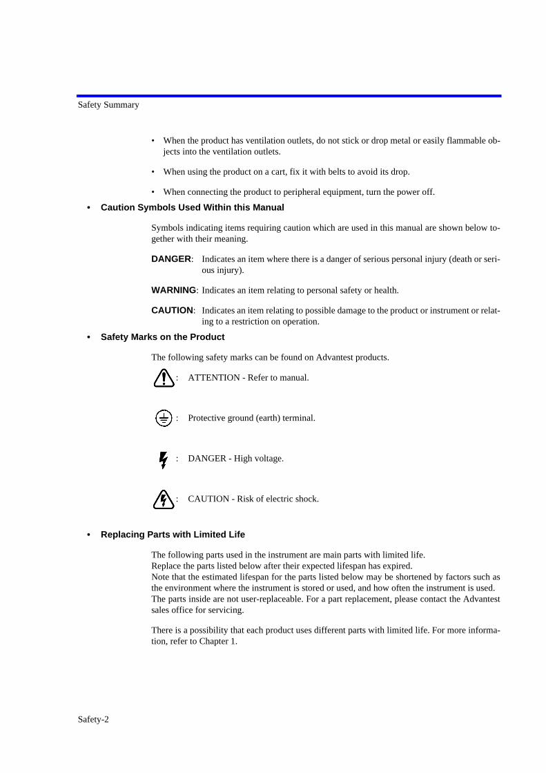
• Safety Marks on the Product
The following safety marks can be found on Advantest products.
: ATTENTION - Refer to manual.
: Protective ground (earth) terminal.
: DANGER - High voltage.
: CAUTION - Risk of electric shock.
• Replacing Parts with Limited Life
The following parts used in the instrument are main parts with limited life.Replace the parts listed below after their expected lifespan has expired.Note that the estimated lifespan for the parts listed below may be shortened by factors such asthe environment where the instrument is stored or used, and how often the instrument is used.The parts inside are not user-replaceable. For a part replacement, please contact the Advantestsales office for servicing.
There is a possibility that each product uses different parts with limited life. For more informa-tion, refer to Chapter 1.
Safety-2

Safety Summary
Main Parts with Limited Life
• Hard Disk Mounted Products
The operational warnings are listed below.
• Do not move, shock and vibrate the product while the power is turned on.Reading or writing data in the hard disk unit is performed with the memory disk turning at ahigh speed. It is a very delicate process.
• Store and operate the products under the following environmental conditions.An area with no sudden temperature changes.An area away from shock or vibrations.An area free from moisture, dirt, or dust.An area away from magnets or an instrument which generates a magnetic field.
• Make back-ups of important data.The data stored in the disk may become damaged if the product is mishandled. The hard dischas a limited life span which depends on the operational conditions. Note that there is noguarantee for any loss of data.
• Precautions when Disposing of this Instrument
When disposing of harmful substances, be sure dispose of them properly with abiding by thestate-provided law.
Harmful substances: (1) PCB (polycarbon biphenyl)(2) Mercury(3) Ni-Cd (nickel cadmium)(4) Other
Items possessing cyan, organic phosphorous and hexadic chromiumand items which may leak cadmium or arsenic (excluding lead in solder).
Example: fluorescent tubes, batteries
Part name Life
Unit power supply 5 years
Fan motor 5 years
Electrolytic capacitor 5 years
LCD display 6 years
LCD backlight 2.5 years
Floppy disk drive 5 years
Safety-3

Environmental Conditions
This instrument should be only be used in an area which satisfies the following conditions:
• An area free from corrosive gas
• An area away from direct sunlight
• A dust-free area
• An area free from vibrations
Figure-1 Environmental Conditions
• Operating position
Figure-2 Operating Position
• Storage position
Figure-3 Storage Position
This instrument can be used safely under the following conditions:
• Altitude of up to 2000 m
• Installation Categories II
• Pollution Degree 2
Vibration
Direct sunlight
Corrosivegas
Dust
Front
Keep at least 10 centimeters of spacebetween the rear panel and any othersurface
FrontThis instrument should be stored in a horizontalposition.When placed in a vertical (upright) position forstorage or transportation, ensure the instrument isstable and secure.
-Ensure the instrument is stable.-Pay special attention not to fall.
Safety-4

R3267 Series OPT67 1xEV-DO(HDR) Measurement Option Operation Manual
PREFACE
PREFACE
This manual provides the information necessary to check functionality, operate and program the R3267 Series Op-tion 67, HDR measurement.
(1) Organization of this manual
This manual consists of the following chapters:
Safety Summary To use the analyzer safely, be sure to read this manual first.
1. INTRODUCTION
• Product Overview• Accessories• Self Test Function• About Calibration• Explanation of the Connectors
Includes a description of the option and its accessories and a self test error messages.
2. MEASUREMENT EXAMPLES
• Measuring the Code Domain of Access Network Signals• Measuring the Frame Analysis of Access Network Signals• CCDF Measurement• Measuring the Pilot/MAC Channel Power of
Access Network Signals• Measuring the Total Power of Access Network Signals
You can learn the basic operations of the option through the examples shown in this chapter.
3. REFERENCE
• Menu Index• Menu Map• Functional Description
Shows a list of operation keys, and describes the function of each key.
4. REMOTE CONTROL
• GPIB Command Index• GPIB Command Codes
Included are a list of commands necessary for programming.
5. TECHNICAL INFORMATION
• Template Edit Function• Measurement Parameter Settings in Due to Transient, Due to
Modulation and Inband Spurious
• Peak Factor of Tx Power• Trigger Source INTRVL (EXT) and INTRVL• About Complementary Filter• About Equalizing Filter• Block Diagram
Describes the principle of operation nec-essary for taking measurements more accurately.
6. PERFORMANCE VERIFICATION TEST
• General• Performance Verification Test Procedure• Performance Verification Test Record Sheet
Describes how to test performance.
Preface-1

R3267 Series OPT67 1xEV-DO(HDR) Measurement Option Operation Manual
Preface
(2) Typeface conventions used in this manual
• Panel keys and soft keys are printed in a contrasting typeface to make them stand out from the text asfollows:
Panel keys: Boldface type Example: TRANSIENT Soft keys: Boldface and italic type Example: T-Domain, Detector
• When a series of key operations are described using a comma between two keys.
• There are various soft menus used to switch between two states such as ON/OFF and AUTO/MNL.
For example, when turning off the Window ON/OFF function, the annotation “Window ON/OFF(OFF)” is used.
7. SPECIFICATIONS Shows the specifications of the option.
APPENDIX
• Messages
If an error occurs during operation, an error number and its corresponding error message are displayed. The meaning of each error is explained in this section.
Preface-2

R3267 Series OPT67 1xEV-DO(HDR) Measurement Option Operation Manual
TABLE OF CONTENTS
TABLE OF CONTENTS
1 INTRODUCTION............................................................................................. 1-1
1.1 Product Overview................................................................................................. 1-11.2 Accessories ........................................................................................................... 1-11.3 Self Test Function................................................................................................. 1-11.4 About Calibration ................................................................................................. 1-11.5 Explanation of the Connectors ............................................................................. 1-1
2 MEASUREMENT EXAMPLES .................................................................. 2-1
2.1 Measuring the Code Domain of Access Network Signals ................................... 2-12.2 Measuring the Frame Analysis of Access Network Signals ................................ 2-82.3 CCDF Measurement ............................................................................................. 2-122.4 Measuring the Pilot/MAC Channel Power of Access Network Signals .............. 2-162.5 Measuring the Total Power of Access Network Signals ...................................... 2-20
3 REFERENCE ..................................................................................................... 3-1
3.1 Menu Index........................................................................................................... 3-13.2 Menu Map ............................................................................................................ 3-53.3 Functional Description ......................................................................................... 3-20
3.3.1 Switching Communication Systems .............................................................. 3-213.3.2 T-Domain....................................................................................................... 3-22
3.3.2.1 Power (T-Domain) ....................................................................................... 3-223.3.2.2 ON/OFF Ratio.............................................................................................. 3-253.3.2.3 Spurious (T-Domain) ................................................................................... 3-28
3.3.3 F-Domain ....................................................................................................... 3-313.3.3.1 Power (F-Domain) ....................................................................................... 3-313.3.3.2 OBW ............................................................................................................ 3-343.3.3.3 Due to Transient........................................................................................... 3-353.3.3.4 Due to Modulation ....................................................................................... 3-383.3.3.5 Inband Spurious(1) ...................................................................................... 3-433.3.3.6 Inband Spurious(2) ...................................................................................... 3-463.3.3.7 Outband Spurious ........................................................................................ 3-49
3.3.4 Modulation..................................................................................................... 3-513.3.4.1 Code Domain ............................................................................................... 3-513.3.4.2 Frame Analysis ............................................................................................ 3-533.3.4.3 Power ........................................................................................................... 3-553.3.4.3.1 Tx Power ................................................................................................. 3-553.3.4.3.2 CCDF ...................................................................................................... 3-563.3.4.3.3 Pilot/MAC Channel Power ..................................................................... 3-573.3.4.3.4 Total Power ............................................................................................. 3-59
3.3.4.4 Time & FFT ................................................................................................. 3-603.3.4.5 STD.............................................................................................................. 3-61
C-1

R3267 Series OPT67 1xEV-DO(HDR) Measurement Option Operation Manual
Table of Contents
4 REMOTE CONTROL ..................................................................................... 4-1
4.1 GPIB Command Index ......................................................................................... 4-14.2 GPIB Command Codes ........................................................................................ 4-9
5 TECHNICAL INFORMATION.................................................................... 5-1
5.1 Template Edit Function ........................................................................................ 5-15.1.1 Template Setting in the T-Domain Measuring Mode.................................... 5-15.1.2 Template Setting in the F-Domain Measuring Mode .................................... 5-3
5.2 Measurement Parameter Settings in Due to Transient, Due to Modulation and Inband Spurious.............................................................. 5-4
5.2.1 Marker Edit Function..................................................................................... 5-45.2.2 Measurement results Using Due to Modulation,
Due to Transient and Inband Spurious Modes............................................... 5-55.2.3 Measurement Result of Inband Spurious....................................................... 5-6
5.3 Peak Factor of Tx Power ...................................................................................... 5-75.4 Trigger Source INTRVL (EXT) and INTRVL .................................................... 5-75.5 About Complementary Filter................................................................................ 5-85.6 About Equalizing Filter ........................................................................................ 5-95.7 Block Diagram...................................................................................................... 5-10
6 PERFORMANCE VERIFICATION TEST ............................................... 6-1
6.1 General ................................................................................................................. 6-16.1.1 Introduction.................................................................................................... 6-16.1.2 Test Equipment .............................................................................................. 6-16.1.3 Specifications Required for Test Signals....................................................... 6-26.1.4 Calibration Cycle ........................................................................................... 6-36.1.5 Performance Verification Test Record Sheet ................................................ 6-36.1.6 Performance Verification Procedure ............................................................. 6-3
6.2 Performance Verification Test Procedure ............................................................ 6-46.2.1 Code Domain Measurement in RF Input Mode............................................. 6-46.2.2 Code Domain Measurement in IQ Input Mode ............................................. 6-6
6.3 Performance Verification Test Record Sheet ....................................................... 6-8
7 SPECIFICATIONS........................................................................................... 7-1
APPENDIX ................................................................................................................ A-1
A.1 Messages............................................................................................................... A-1
ALPHABETICAL INDEX .................................................................................... I-1
C-2

R3267 Series OPT67 1xEV-DO(HDR) Measurement Option Operation Manual
LIST OF ILLUSTRATIONS
No. Title Page
2-1 Connection for Code Domain Measurements of the Access Network Signals ................ 2-12-2 STD-Measurement parameter set Dialog Box .................................................................. 2-22-3 Parameter Setup Dialog Box ............................................................................................. 2-32-4 Measurement Results of the HDR Access Network Signal .............................................. 2-42-5 Example of the Marker Display of MAC Code Domain Graph ....................................... 2-72-6 Connection for Frame Analysis Measurements of the Access Network Signals ............ 2-82-7 Parameter Setup Dialog Box ............................................................................................. 2-92-8 Measurement Results of the HDR Access Network Signal .............................................. 2-102-9 Setup for CCDF Measurement ......................................................................................... 2-122-10 Spectrum of the Access Network Signal .......................................................................... 2-132-11 CCDF Parameter Setup Dialog Box ................................................................................. 2-132-12 CCDF Measurement Result .............................................................................................. 2-142-13 CCDF Measurement Result (Trace Write ON) ................................................................ 2-152-14 Connection for Pilot/MAC Channel Power Measurements of
the Access Network Signals ............................................................................................ 2-162-15 Parameter Setup Dialog Box ............................................................................................. 2-172-16 Measurement Results of the HDR Access Network Signal .............................................. 2-182-17 Connection for Total Power Measurements of the Access Network Signals ................... 2-202-18 Parameter Setup Dialog Box ............................................................................................. 2-212-19 Measurement Results of the HDR Access Network Signal .............................................. 2-22
3-1 Communication Systems Dialog Box ............................................................................... 3-213-2 Trigger Setup Dialog Box ................................................................................................. 3-223-3 Parameter Setup Dialog Box ............................................................................................. 3-243-4 Trigger Setup Dialog Box ................................................................................................. 3-253-5 Parameter Setup Dialog Box ............................................................................................. 3-273-6 Trigger Setup Dialog Box ................................................................................................. 3-283-7 Parameter Setup Dialog Box ............................................................................................. 3-293-8 Trigger Setup Dialog Box ................................................................................................. 3-313-9 Detector Dialog Box ......................................................................................................... 3-323-10 Parameter Setup Dialog Box ............................................................................................. 3-333-11 Parameter Setup Dialog Box ............................................................................................. 3-343-12 Parameter Setup Dialog Box ............................................................................................. 3-363-13 Trigger Setup Dialog Box ................................................................................................. 3-383-14 Detector Dialog Box ......................................................................................................... 3-403-15 Parameter Setup Dialog Box ............................................................................................. 3-413-16 Parameter Setup Dialog Box ............................................................................................. 3-443-17 Parameter Setup Dialog Box ............................................................................................. 3-473-18 Parameter Setup Dialog Box ............................................................................................. 3-503-19 Graph Type Setting Examples .......................................................................................... 3-513-20 Parameter Setting Examples ............................................................................................. 3-523-21 Parameter Setting Examples ............................................................................................. 3-533-22 Parameter Setup Dialog Box ............................................................................................. 3-553-23 Scale Setup Dialog Box .................................................................................................... 3-563-24 Parameter Setup Dialog Box ............................................................................................. 3-573-25 Parameter Setting Examples ............................................................................................. 3-58
F-1
R3267 Series OPT67 1xEV-DO(HDR) Measurement Option Operation Manual
List of Illustrations
No. Title Page
3-26 Parameter Setting Examples ............................................................................................. 3-593-27 Select Type Dialog Box .................................................................................................... 3-603-28 Parameter Setup Dialog Box ............................................................................................. 3-603-29 STD Measurement Parameter Set Dialog Box ................................................................. 3-61
5-1 Template to Be Set ............................................................................................................ 5-15-2 Template Settings ............................................................................................................. 5-25-3 Template Shifted Using the Shift Y Function .................................................................. 5-25-4 Template with the Set Values ........................................................................................... 5-35-5 Template with Margin Delta X ......................................................................................... 5-35-6 Example of Marker Edit Setting (1) ................................................................................. 5-45-7 Example of Marker Edit Setting (2) ................................................................................. 5-55-8 Example of Peak Marker Y Delta ..................................................................................... 5-55-9 Block Diagram .................................................................................................................. 5-10
6-1 Timing Chart of Trigger signal and Traffic (QPSK) signal (Not Scaled) ........................ 6-36-2 Setup of Code Domain Measurement (in RF Input) ......................................................... 6-46-3 Measurement Parameters for Code Domain (RF Input) ................................................... 6-56-4 Setup of Code Domain Measurement (in IQ Input) ......................................................... 6-66-5 Measurement Parameters for Code Domain (IQ Input) .................................................... 6-7
F-2

R3267 Series OPT67 1xEV-DO(HDR) Measurement Option Operation Manual
LIST OF TABLES
No. Title Page
4-1 Operating Mode ................................................................................................................ 4-94-2 ATT Key (Attenuator) ...................................................................................................... 4-94-3 COPY Key (Hard copy) .................................................................................................... 4-94-4 COUPLE Key (Couple function) ...................................................................................... 4-104-5 FREQ Key (Frequency) .................................................................................................... 4-104-6 LEVEL Key (Reference Level) ........................................................................................ 4-104-7 MKR Key (Marker) .......................................................................................................... 4-114-8 PRESET Key (Initialization) ............................................................................................ 4-114-9 RCL Key (Recall) ............................................................................................................. 4-114-10 SAVE Key (Save) ............................................................................................................. 4-124-11 SPAN Key (Frequency span) ............................................................................................ 4-124-12 TRANSIENT Key ............................................................................................................. 4-134-13 Numeric Keys/Step Keys/Data Knob/Unit Keys (Entering Data) .................................... 4-484-14 Miscellaneous ................................................................................................................... 4-49
6-1 Performance Verification Items ........................................................................................ 6-16-2 Equipment List .................................................................................................................. 6-26-3 Specifications Required for Test Signals .......................................................................... 6-2
T-1
R3267 Series OPT67 1xEV-DO(HDR) Measurement Option Operation Manual
1 INTRODUCTION
1 INTRODUCTION
1.1 Product Overview
The HDR modulation analysis option (OPT67) software allows you to measure and evaluate the modulationaccuracy specified by IS-856.
This option is a factory option which is incorporated into the R3267 Series Spectrum Analyzer prior to ship-ment.
This option includes the following features:
• Measures the frequency error, code domain power and so on.
• Can be used to measure OBW or ACP due to Transient specified by the communication standard with a simple key operation.
1.2 Accessories
1.3 Self Test Function
The self test also checks the Option 67 for correct operation when the spectrum analyzer power is turned on.The message shown below will be displayed when an error related to Option 67 occurs. Contact ADVANTEST Corp. for repair.
1.4 About Calibration
When you want to calibrate the R3267 Series, please contact a sales representative.
1.5 Explanation of the Connectors
Connectors used for this option are described as follows:
1. EXT TRIG terminal Connector for inputting the external trigger signal.
Name of accessories Type of name Quantity Remarks
R3267 Series option 67 Operation manual
ER3267/73OPT67 1
Error Message
Handshake error occurred to DSP
Desirable Period 1 year
1-1

R3267 Series OPT67 1xEV-DO(HDR) Measurement Option Operation Manual
2 MEASUREMENT EXAMPLES
2 MEASUREMENT EXAMPLES
This chapter describes how to use this option using practical measurement examples.
2.1 Measuring the Code Domain of Access Network Signals
This section provides measurement examples for the code domain when it is used to analyze the Accecss Net-work signal.
Measurement conditions:
Measured signals have an output signal with a frequency of 870.03 MHz and a level of -10 dBm based onIS-856.It is assumed that the Even Second clock, 10 MHz reference signal and measurement signals are output.
Signal specifications:
Slot Structure
Active slot
Modulation Parameters
Data Rate: 614.4 kbps
Modulation Type: QPSK
RA channel
MACIndex: 4
Connecting the equipment
1. Connect the equipment as shown in Figure 2-1.
Figure 2-1 Connection for Code Domain Measurements of the Access Network Signals
AN
Measurement signal (RF signal)
2-1

R3267 Series OPT67 1xEV-DO(HDR) Measurement Option Operation Manual
2.1 Measuring the Code Domain of Access Network Signals
Setting the measurement conditions
This changes the analyzer setting so that the input signal displayed more clearly.
2. Press FREQ, 8, 7, 0, ., 0, 3 and MHz.
3. Press SPAN, 8 and MHz.
4. Press LEVEL, 0 and GHz(+dBm).
5. Press TRANSIENT, STD and STD Setup.The STD Measurement Parameter Set dialog box is displayed.
Figure 2-2 STD-Measurement parameter set Dialog Box
6. Press the key.The cursor moves to the item Signal Type.
7. Select CONTINUOUS from Signal Type using the data knob, and pressHz(ENTR).
The following parameters are default settings.
Offset Level: 0.0 dBFrequency Input: FREQUENCYChannel Setting: FORWARDInput: RFIQ Inverse: NORMALCont Auto Level Set: OFF
2-2

R3267 Series OPT67 1xEV-DO(HDR) Measurement Option Operation Manual
2.1 Measuring the Code Domain of Access Network Signals
8. Press RETURN, Modulation, Code Domain and Parameter Setup.The Parameter Setup dialog box is displayed.
Figure 2-3 Parameter Setup Dialog Box
9. Press 0, ., 2, and Hz(ENTR) to set Complementary Filter Rolloff.The roll-off coefficient after passing through the complementary filter is set to0.2.
10. Select ON from Equalizing Filter using the data knob, and press Hz(ENTR).The phase characteristics of the complimentary filter are set to the inverse char-acteristics of the phase equalizer.
11. Press 0 and Hz(ENTR) to set PN Offset.The PN offset is set to 0.
12. Press -, 2, 7, and GHz(dB) to set MAC Threshold.
13. Select EXT from Trigger Source using the data knob, and press Hz(ENTR).The trigger is set to the external trigger.
14. Select + from EXT Trigger Slope using the data knob, and press Hz(ENTR).
15. Press Parameter Setup.The dialog box is closed.
2-3

R3267 Series OPT67 1xEV-DO(HDR) Measurement Option Operation Manual
2.1 Measuring the Code Domain of Access Network Signals
16. Press Auto Level Set.The measurement range is set to the optimum range.
17. Press SINGLE.The sweep is set to a single mode and starts.
Figure 2-4 Measurement Results of the HDR Access Network Signal
Carrier Frequency Error
The carrier frequency error from the center frequency which hasbeen set (Hz, ppm)
The value collected is for 10 Pilot Channel slots.
Pilot Time Alignment Error
Time delay from the trigger (µs) to the head of the frame
The value collected is for 10 Pilot Channel slots.If an Even Second signal is entered as the external trigger signal,the pilot time alignment error, which is the Minimum Standard forPilot Channel Tolerance is collected.
ρ pilot Waveform quality of the Pilot Channel
The value collected is for 10 Pilot Channel slots. (N = 20 : 20 half slots)ρ pilot, one of the Minimum Standards for the Waveform Qualityis collected.
2-4

R3267 Series OPT67 1xEV-DO(HDR) Measurement Option Operation Manual
2.1 Measuring the Code Domain of Access Network Signals
ρ overall-1 Waveform quality in the Pilot Channel, MAC Channel and Traf-fic or Control Channel
The value collected is for one Pilot Channel slot. (N = 2 : 2 half slots)First, an automatic scan is done to check if the slot is idle or active.Then, the slot is checked for an existence of the pre-amble and themodulation type is decided from QPSK, 8-PSK, or 16-QAM.ρ overall-1, one of the Minimum Standards for the WaveformQuality is collected.
overall-2 Waveform quality in the Pilot Channel, MAC Channel, and Traf-fic or Control Channel with all of them shifted 512 chips from
those of the ρ overall-1
The value collected is for one Pilot Channel slot. (N = 2 : 2 half slots)It runs the same decision making processes as in ρ overall-1.ρ overall-2, one of the Minimum Standards for the WaveformQuality is collected.
Peak MAC Inactive Channel
The maximum and logarithmic values of 8-slot code domainpower ρMAC, real (i) and ρMAC, imag (i) of the MAC Channels whichare determined as inactive (dB). (N = 16 : 16 half slots)
MAC Channels are determined as inactive when one of the fol-lowing conditions is met:
1. The ρMAC, real (i) and ρMAC, imag (i) values are less than theMAC threshold value.
2. The MAC Channel is not for MACIndex.
Therefore, even though the ρMAC, real (i) and ρMAC, imag (i) valuesexceed the MAC threshold value, MAC Channels of ρMAC, real (i)with the Walsh Code 32 to 63 are determined as inactive becausethese channels are not for MACIndex. In the same manner, MACChannels of ρMAC, imag (i) with the Walsh Code 0 to 31 are deter-mined as inactive because these channels are not for MACIndex.
The logarithmic value set in the Parameter Setup dialog box isused as the MAC threshold value.The Minimum Standard value for Code Domain Power of MACchannel can be obtained.
2-5

R3267 Series OPT67 1xEV-DO(HDR) Measurement Option Operation Manual
2.1 Measuring the Code Domain of Access Network Signals
Max Data Code Domain
The maximum and logarithmic values of 2-slot code domainpower ρData, real (i) and ρDATA, imag (i) of the 16 orthogonal codechannels (dB). Preambles of Control and Forward Traffic Chan-nels are excluded. (N = 4 : 4 half slots)In case of an idle slot, “*” is displayed.The Minimum Standard for the Code Domain Power of ForwardTraffic and Control Channel is collected.
Min Data Code Domain
The minimum and logarithmic values of code domain powerρ
Data, real (i) and ρDATA, imag (i) of the 16 orthogonal code channels(dB). Preambles of Control and Forward Traffic Channels areexcluded.
Modulation Type
Modulation type for the Control Channel or Forward TrafficChannel of the slot which the ρ overall-1 was collected for (QPSK, 8-PSK, 16-QAM)
In case of an idle slot, “idle” is displayed.
PN Offset PN offset value for the Pilot PN Sequence
The offset value assigned with the Parameter Setup in the dialogbox is displayed. However, if a signal other than the one assignedwith the Parameter Setup is entered, the trigger will assume thatthe even second time reference signal is being assigned and willsearch for a PN offset.
Preamble Chips(ρ overall-1)
Chip number that is equivalent to the number of pre-ambles in theslots which the ρ overall-1 was collected for.
18. Press MKR.The maker is displayed.
19. Select 2 from MKR POSI. using the data knob.
2-6
R3267 Series OPT67 1xEV-DO(HDR) Measurement Option Operation Manual
2.1 Measuring the Code Domain of Access Network Signals
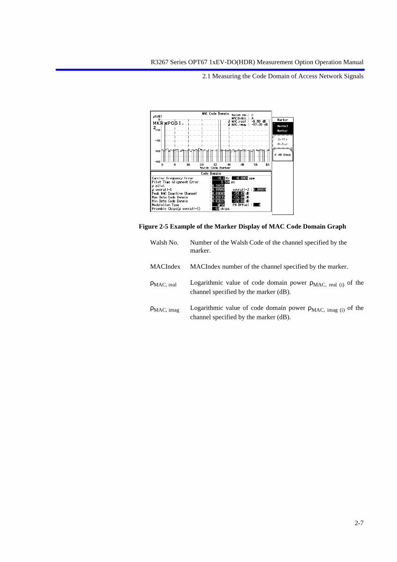
Figure 2-5 Example of the Marker Display of MAC Code Domain Graph
Walsh No. Number of the Walsh Code of the channel specified by the marker.
MACIndex MACIndex number of the channel specified by the marker.
ρMAC, real Logarithmic value of code domain power ρMAC, real (i) of thechannel specified by the marker (dB).
ρMAC, imag Logarithmic value of code domain power ρMAC, imag (i) of thechannel specified by the marker (dB).
2-7
R3267 Series OPT67 1xEV-DO(HDR) Measurement Option Operation Manual
2.2 Measuring the Frame Analysis of Access Network Signals
2.2 Measuring the Frame Analysis of Access Network Signals
This section provides measurement examples for the Frame Analysis when it is used to analyze the AccecssNetwork signal.
Measurement conditions:
Measured signals have an output signal with a frequency of 870.03 MHz and a level of -10 dBm based onIS-856.It is assumed that the Even Second clock, 10 MHz reference signal and measurement signals are output.
Signal specifications:
Slot Structure
Active slot
Modulation Parameters
Data Rate: 614.4 kbps
Modulation Type: QPSK
RA channel
MACIndex: 4
Connecting the equipment
1. Connect the equipment as shown in Figure 2-6.
Figure 2-6 Connection for Frame Analysis Measurements of the Access Network Signals
AN
Measurement signal (RF signal)
2-8

R3267 Series OPT67 1xEV-DO(HDR) Measurement Option Operation Manual
2.2 Measuring the Frame Analysis of Access Network Signals
Setting the measurement conditions
This changes the analyzer setting so that the input signal displayed more clearly.
2. Press FREQ, 8, 7, 0, ., 0, 3 and MHz.
3. Press SPAN, 8 and MHz.
4. Press LEVEL, 0 and GHz(+dBm).
5. Press TRANSIENT, STD and STD Setup.The STD Measurement Parameter Set dialog box is displayed.
6. Press the key.The cursor moves to the item Signal Type.
7. Select CONTINUOUS from Signal Type using the data knob, and pressHz(ENTR).
The following parameters are default settings.
Offset Level: 0.0 dBFrequency Input: FREQUENCYChannel Setting: FORWARDInput: RFIQ Inverse: NORMALCont Auto Level Set: OFF
8. Press RETURN, Modulation, Frame Analysis and Parameter Setup.The Parameter Setup dialog box is displayed.
Figure 2-7 Parameter Setup Dialog Box
9. Press 0, ., 2, and Hz(ENTR) to set Complementary Filter Rolloff.The roll-off coefficient after passing through the complementary filter is set to0.2.
2-9

R3267 Series OPT67 1xEV-DO(HDR) Measurement Option Operation Manual
2.2 Measuring the Frame Analysis of Access Network Signals
10. Select ON from Equalizing Filter using the data knob, and press Hz(ENTR).The phase characteristics of the complimentary filter are set to the inverse char-acteristics of the phase equalizer.
11. Press 0 and Hz(ENTR) to set PN Offset.The PN offset is set to 0.
12. Press -, 2, 7, and GHz(dB) to set MAC Threshold.
13. Select EXT from Trigger Source using the data knob, and press Hz(ENTR).The trigger is set to the external trigger.
14. Select + from EXT Trigger Slope using the data knob, and press Hz(ENTR).
15. Press Parameter Setup.The dialog box is closed.
16. Press Auto Level Set.The measurement range is set to the optimum range.
17. Press SINGLE.The sweep is set to a single mode and starts.
Figure 2-8 Measurement Results of the HDR Access Network Signal
Mod. Type Modulation types for the Control or Forward Traffic Channel foreach slot. (QPSK, 8-PSK, and 16-QAM)
For an idle slot, “idle” is displayed.
Preamble [chips]
Chip number that is equivalent to the number of pre-ambles ineach slots.
2-10
R3267 Series OPT67 1xEV-DO(HDR) Measurement Option Operation Manual
2.2 Measuring the Frame Analysis of Access Network Signals
MAC(MACIndex)
Indicates active MAC Channels for each slot using 64-bit valuesin hexadecimal code.
Displays these values according to the MACIndex order.A bit set to 1 indicates that the MAC channel is active. Values 0c00 0000 0000 0000 indicate that MAC channels for theMACIndex number 4 and 5 are active.
Carrier Frequency Error
The carrier frequency error from the center frequency which hasbeen set (Hz)
The value collected is for 10 Pilot Channel slots.
Pilot Time Alignment Error
Time delay from the trigger (µs) to the head of the frame
The value collected is for 10 Pilot Channel slots.If an Even Second signal is entered as the external trigger signal,the pilot time alignment error, which is the Minimum Standard forPilot Channel Tolerance is collected.
PN Offset PN offset value for the Pilot PN Sequence
The offset value assigned with the Parameter Setup in the dialogbox is displayed. However, if a signal other than the one assignedwith the Parameter Setup is entered, the trigger will assume thatthe even second time reference signal is being assigned and willsearch for a PN offset.
ρ pilot Waveform quality of the Pilot Channel
The value collected is for 10 Pilot Channel slots. (N = 20 : 20 half slots)ρ pilot, one of the Minimum Standards for the Waveform Qualityis collected.
2-11

R3267 Series OPT67 1xEV-DO(HDR) Measurement Option Operation Manual
2.3 CCDF Measurement
2.3 CCDF Measurement
The CCDF (Complementary Cumulative Distribution Function) can be measured.
Setup
1. Connect the unit under test as shown in Figure 2-9.
Figure 2-9 Setup for CCDF Measurement
Setting the measurement conditions
This changes the analyzer setting so that the input signal may be displayed moreclearly.
2. Press FREQ, 8, 7, 0, ., 0, 3 and MHz.A center frequency of 870.03 MHz is set.
3. Press SPAN, 2 and MHz.A frequency span of 2 MHz is set.
4. Press COUPLE, RBW AUTO/MNL(MNL), 3, 0 and kHz.An RBW of 30 kHz is set.
5. Press VBW AUTO/MNL(MNL), 1, 0, 0 and kHz.A VBW of 100 kHz is set.
6. Press LEVEL, 0 and GHz(+dBm).The reference level is set to 0 dBm.
Spectrum analyzer Access Network
REF IN 10 MHz Reference
RF Tx
2-12

R3267 Series OPT67 1xEV-DO(HDR) Measurement Option Operation Manual
2.3 CCDF Measurement
Figure 2-10 Spectrum of the Access Network Signal
CCDF Measurement
7. Press TRANSIENT, Modulation, Power, CCDF and Parameter Setup.The Parameter Setup dialog box is displayed.
8. Select INT from Trigger Mode using the data knob, and press Hz(ENTR).The measurement mode is set to a mode that uses the internal trigger.
9. Press 1, 0 and kHz to set Meas Length.The number of measurement samples is set to 10k.
Figure 2-11 CCDF Parameter Setup Dialog Box
10. Press Parameter Setup.The dialog box is removed.
11. Press Auto Level Set.The measurement range is optimally set.
2-13

R3267 Series OPT67 1xEV-DO(HDR) Measurement Option Operation Manual
2.3 CCDF Measurement
12. Press SINGLE.The measurement mode is set to the single mode and the measurement mode isdisplayed.
Figure 2-12 CCDF Measurement Result
Peak Factor Peak factorAverage Power Average power[10%] Power whose distribution is 10%[1%] Power whose distribution is 1%[0.1%] Power whose distribution is 0.1%[0.01%] Power whose distribution is 0.01%[0.001%] Power whose distribution is 0.001%[0.0001%] Power whose distribution is 0.0001%
Holding waveform
13. Press Trace Write ON/OFF(ON).The signal waveform is held.
14. Press SINGLE.The measurement mode is set to SINGLE mode so that both the stored and cur-rent waveforms are displayed.
2-14
R3267 Series OPT67 1xEV-DO(HDR) Measurement Option Operation Manual
2.3 CCDF Measurement
Figure 2-13 CCDF Measurement Result (Trace Write ON)
2-15

R3267 Series OPT67 1xEV-DO(HDR) Measurement Option Operation Manual
2.4 Measuring the Pilot/MAC Channel Power of Access Network Signals
2.4 Measuring the Pilot/MAC Channel Power of Access Network Signals
This section provides measurement examples for the Pilot/MAC Channel Power when it is used to analyzethe Accecss Network signal.
Measurement conditions:
Measured signals have an output signal with a frequency of 870.03 MHz and a level of -10 dBm based onIS-856.It is assumed that the Even Second clock, 10 MHz reference signal and measurement signals are output.
Signal specifications:
Slot Structure
Idle slot
Connecting the equipment
1. Connect the equipment as shown in Figure 2-14.
Figure 2-14 Connection for Pilot/MAC Channel Power Measurements of the Access Network Signals
Setting the measurement conditions
This changes the analyzer setting so that the input signal displayed more clearly.
2. Press FREQ, 8, 7, 0, ., 0, 3 and MHz.
3. Press SPAN, 8 and MHz.
4. Press LEVEL, 0 and GHz(+dBm).
5. Press TRANSIENT, STD and STD Setup.The STD Measurement Parameter Set dialog box is displayed.
6. Press the key.The cursor moves to the item Signal Type.
AN
Measurement signal (RF signal)
2-16

R3267 Series OPT67 1xEV-DO(HDR) Measurement Option Operation Manual
2.4 Measuring the Pilot/MAC Channel Power of Access Network Signals
7. Select CONTINUOUS from Signal Type using the data knob, and pressHz(ENTR).
The following parameters are default settings.
Offset Level: 0.0 dBFrequency Input: FREQUENCYChannel Setting: FORWARDInput: RFIQ Inverse: NORMALCont Auto Level Set: OFF
8. Press RETURN, Modulation, Power, Pilot/MAC Channel Power, TemplateEntry and STD Template.The Template value is set to the standard value.
9. Press RETURN and Parameter Setup.
Figure 2-15 Parameter Setup Dialog Box
10. Press 0 and Hz(ENTR) to set PN Offset.The PN offset is set to 0.
11. Set Bandpass Filter to OFF using the data knob, and press Hz(ENTR).
12. Select EXT from Trigger Source using the data knob, and press Hz(ENTR).The trigger is set to the external trigger.
13. Select + from EXT Trigger Slope using the data knob, and press Hz(ENTR).
14. Press Parameter Setup.The dialog box is closed.
2-17

R3267 Series OPT67 1xEV-DO(HDR) Measurement Option Operation Manual
2.4 Measuring the Pilot/MAC Channel Power of Access Network Signals
15. Press Auto Level Set.The measurement range is set to the optimum range.
16. Press SINGLE.The sweep is set to a single mode and starts.
Figure 2-16 Measurement Results of the HDR Access Network Signal
Average / Average count
The numerator indicates the average count of the displayed wave-forms.
PN Offset PN offset value for the Pilot PN Sequence
The offset value assigned with the Parameter Setup in the dialogbox is displayed. However, if a signal other than the one assignedwith the Parameter Setup is entered, the trigger will assume thatthe even second time reference signal is being assigned and willsearch for a PN offset.
Burst Length The burst-on length (µs)
Obtains the burst length within the template levels Y0 and Y1.The length indicates between the center of the template and thepoint where the burst exceeds the Y0 and Y1 levels.
ON Avg. Average power within the burst-on (222 chips) period (dBm).
Obtains sampled average power within the burst-on (222 chips)period of the ensemble average waveform.
(ON) Max. The maximum value within the burst-on (7 µs + 222 chips + 7 µs)period (dB).
The value is expressed as relative power (dB) when ON Avg.(average power) is set to 0 dB.
2-18

R3267 Series OPT67 1xEV-DO(HDR) Measurement Option Operation Manual
2.4 Measuring the Pilot/MAC Channel Power of Access Network Signals
(ON) Min. The minimum value within the burst-on (222 chips) period (dB).
OFF Avg. Relative average power within the burst-off (other than 7 µs + 222chips + 7 µs within the burst-on period) period (dB).
(OFF) Max. The maximum value within the burst-off (other than 7 µs + 222chips + 7 µs within the burst-on period) period (dB).To judge PASS or FAIL, Y0, Y1, and Y2 template levels can becompared with (ON) Min., (ON) Max., and (OFF) Max.
Rise The rise time length of the burst. (µs)
Obtains the time length between the rising edge of the burst-on(222 chips) period and the point where the burst waveform isbelow the Y2 level.
Fall The fall time length of the burst. (µs)
Obtains the time length between the falling edge of the burst-on(222 chips) period and the point where the burst waveform isbelow the Y2 level.
2-19

R3267 Series OPT67 1xEV-DO(HDR) Measurement Option Operation Manual
2.5 Measuring the Total Power of Access Network Signals
2.5 Measuring the Total Power of Access Network Signals
This section provides measurement examples for the Total Power when it is used to analyze the Accecss Net-work signal.
Measurement conditions:
Measured signals have an output signal with a frequency of 870.03 MHz and a level of -10 dBm based onIS-856.It is assumed that the Even Second clock, 10 MHz reference signal and measurement signals are output.
Signal specifications:
Slot Structure
Active slot
Connecting the equipment
1. Connect the equipment as shown in Figure 2-17.
Figure 2-17 Connection for Total Power Measurements of the Access Network Signals
Setting the measurement conditions
This changes the analyzer setting so that the input signal displayed more clearly.
2. Press FREQ, 8, 7, 0, ., 0, 3 and MHz.
3. Press SPAN, 8 and MHz.
4. Press LEVEL, 0 and GHz(+dBm).
5. Press TRANSIENT, STD and STD Setup.The STD Measurement Parameter Set dialog box is displayed.
6. Press the key.The cursor moves to the item Signal Type.
AN
Measurement signal (RF signal)
2-20

R3267 Series OPT67 1xEV-DO(HDR) Measurement Option Operation Manual
2.5 Measuring the Total Power of Access Network Signals
7. Select CONTINUOUS from Signal Type using the data knob, and pressHz(ENTR).
The following parameters are default settings.
Offset Level: 0.0 dBFrequency Input: FREQUENCYChannel Setting: FORWARDInput: RFIQ Inverse: NORMALCont Auto Level Set: OFF
8. Press RETURN, Modulation, Power, Total Power, Template Entry and STDTemplate.The Template value is set to the standard value.
9. Press RETURN and Parameter Setup.
Figure 2-18 Parameter Setup Dialog Box
10. Press 0 and Hz(ENTR) to set PN Offset.The PN offset is set to 0.
11. Set Bandpass Filter to OFF using the data knob, and press Hz(ENTR).
12. Select EXT from Trigger Source using the data knob, and press Hz(ENTR).The trigger is set to the external trigger.
13. Select + from EXT Trigger Slope using the data knob, and press Hz(ENTR).
14. Press Parameter Setup.The dialog box is closed.
2-21

R3267 Series OPT67 1xEV-DO(HDR) Measurement Option Operation Manual
2.5 Measuring the Total Power of Access Network Signals
15. Press Auto Level Set.The measurement range is set to the optimum range.
16. Press SINGLE.The sweep is set to a single mode and starts.
Figure 2-19 Measurement Results of the HDR Access Network Signal
Average / Average count
The numerator indicates the average count of the displayed wave-forms.The denominator indicates the final average count set for AverageTimes.
PN Offset PN offset value for the Pilot PN Sequence
The offset value assigned with the Parameter Setup in the dialogbox is displayed. However, if a signal other than the one assignedwith the Parameter Setup is entered, the trigger will assume thatthe even second time reference signal is being assigned and willsearch for a PN offset.
Average Power
Average power of the entire waveform (dBm).
Maximum Power
The maximum power of the entire waveform (dB).The value is expressed as relative power (dB) when averagepower is set to 0 dB.
Minimum Power
The minimum power of the entire waveform (dB).
2-22

R3267 Series OPT67 1xEV-DO(HDR) Measurement Option Operation Manual
3 REFERENCE
3 REFERENCE
This chapter describes the functions of the panel and soft keys for option 67 software.
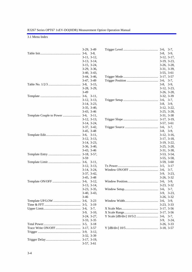
3.1 Menu Index
This menu index is used to easily find the keys described in Chapter 3.
Operation Key Pages Operation Key Pages
Average Mode.......................................... 3-6, 3-7, 3-8, 3-9, 3-10, 3-11, 3-12, 3-13, 3-14, 3-15, 3-24, 3-27, 3-30, 3-33, 3-35, 3-38, 3-42, 3-45, 3-48, 3-50
Average Times ON/OFF.......................... 3-6, 3-7, 3-8, 3-9, 3-10, 3-11, 3-12, 3-13, 3-14, 3-15, 3-17, 3-18, 3-19, 3-24, 3-26, 3-29, 3-33, 3-34, 3-36, 3-40, 3-44, 3-47, 3-49, 3-56, 3-58, 3-60, 3-61
Auto Level Set ......................................... 3-6, 3-7, 3-8, 3-9, 3-10, 3-11, 3-12, 3-13, 3-14, 3-15, 3-16, 3-17, 3-18, 3-19, 3-22, 3-25, 3-28, 3-31, 3-34, 3-35, 3-38, 3-43, 3-46, 3-49, 3-51, 3-53, 3-55, 3-56, 3-57, 3-59, 3-60
CCDF ....................................................... 3-5, 3-17
3-1
Band Class ............................................... 3-19, 3-61Band Conversion...................................... 3-14Bandpass Filter ........................................ 3-18, 3-58,
3-59Baseband Input ........................................ 3-19, 3-62Channel Setting........................................ 3-19, 3-62Code Domain ........................................... 3-5Complementary Filter Rolloff ................. 3-16, 3-52,
3-53Config ...................................................... 3-6, 3-7,
3-8, 3-9, 3-10, 3-11, 3-12, 3-13, 3-14, 3-15, 3-24, 3-26, 3-29, 3-33, 3-34, 3-36, 3-41, 3-44, 3-47, 3-50
Cont Auto Level Set ................................ 3-19, 3-63Copy from STD ....................................... 3-6, 3-11,
3-12, 3-13, 3-14, 3-15, 3-19, 3-23, 3-36, 3-40, 3-43, 3-46, 3-49, 3-61
DC CAL................................................... 3-19EXT Trigger Delay .................................. 3-17, 3-56EXT Trigger Slope................................... 3-16, 3-17,
3-18, 3-53, 3-54, 3-55, 3-58, 3-60
Data Code Domain................................... 3-16, 3-51Data Despread Constellation ................... 3-16, 3-52Edit Table 1 2 3........................................ 3-19, 3-61Edit Table 4 5 6........................................ 3-19, 3-61Edit Table 7 8 9........................................ 3-19, 3-61Delay Time .............................................. 3-6, 3-7,
3-8, 3-9, 3-12, 3-23,

R3267 Series OPT67 1xEV-DO(HDR) Measurement Option Operation Manual
3.1 Menu Index
3-26, 3-28, 3-32, 3-39
Delete ....................................................... 3-15Delete Line............................................... 3-6, 3-8,
3-11, 3-12, 3-13, 3-14, 3-23, 3-29, 3-36, 3-40, 3-43, 3-46, 3-47, 3-49
Detector.................................................... 3-6, 3-7, 3-8, 3-9, 3-10, 3-11, 3-12, 3-13, 3-14, 3-15, 3-24, 3-27, 3-29, 3-32, 3-33, 3-34, 3-37, 3-40, 3-41, 3-44, 3-47, 3-50
Display Unit ............................................. 3-6, 3-7, 3-8, 3-9, 3-11, 3-12, 3-13, 3-14, 3-15, 3-24, 3-27, 3-29, 3-33, 3-37, 3-41, 3-45, 3-48, 3-50
Equalizing Filter ...................................... 3-16, 3-52, 3-54
Due to Modulation ................................... 3-5Due to Transient....................................... 3-5Ext Gate ................................................... 3-9, 3-12,
3-32, 3-39F-Domain ................................................. 3-5Gate Position............................................ 3-9, 3-12,
3-32, 3-39Gate Setup................................................ 3-9, 3-12,
3-31, 3-32, 3-38, 3-39
Gate Source.............................................. 3-9, 3-12, 3-32, 3-39
Gate Width............................................... 3-9, 3-12, 3-32, 3-39
Gated Sweep ............................................ 3-9, 3-33Gated Sweep ON/OFF ............................. 3-9, 3-12,
3-32, 3-39Frame Analysis ........................................ 3-5, 3-16Graph Type .............................................. 3-16, 3-51
3-2
Freq. Setting............................................. 3-11, 3-12, 3-13, 3-14, 3-37, 3-41, 3-44, 3-47
Frequency Input ....................................... 3-19, 3-62IQ Complex FFT...................................... 3-19IQ Inverse ................................................ 3-19, 3-62Ich & Qch Time ....................................... 3-19Ich Time & FFT....................................... 3-19Inband Spurious(1) .................................. 3-5Inband Spurious(2) .................................. 3-5Input ......................................................... 3-19, 3-62Insert Line ................................................ 3-6, 3-8,
3-11, 3-12, 3-13, 3-14, 3-15, 3-23, 3-29, 3-36, 3-40, 3-43, 3-46, 3-49
Integral Band............................................ 3-14, 3-48Judgment.................................................. 3-6, 3-7,
3-8, 3-9, 3-10, 3-11, 3-12, 3-13, 3-14, 3-15, 3-24, 3-27, 3-30, 3-33, 3-34, 3-37, 3-42, 3-45, 3-48, 3-50
MAC Code Domain ................................. 3-16, 3-51MAC Threshold ....................................... 3-16, 3-53,
3-54Margin ∆X ON/OFF ................................ 3-11, 3-12,
3-13, 3-14, 3-36, 3-40, 3-43, 3-46
Marker Edit .............................................. 3-11, 3-12, 3-13, 3-14, 3-36, 3-40, 3-43, 3-46
Meas Length ............................................ 3-17, 3-57Load Table ............................................... 3-8, 3-15,
3-29, 3-49Modulation............................................... 3-5Lower Limit ............................................. 3-6, 3-9,
3-10, 3-24, 3-33, 3-35
Multiplier ................................................. 3-8, 3-29OBW ........................................................ 3-5OBW%..................................................... 3-10, 3-34
R3267 Series OPT67 1xEV-DO(HDR) Measurement Option Operation Manual
3.1 Menu Index
OFF Position ............................................ 3-7, 3-26OFF Width ............................................... 3-7, 3-26ON Position.............................................. 3-7, 3-26ON Width................................................. 3-7, 3-26ON/OFF Ratio.......................................... 3-5, 3-7Offset Level ............................................. 3-19, 3-62Outband Spurious .................................... 3-5PN Offset ................................................. 3-16, 3-18,
3-53, 3-54, 3-58, 3-59
Parameter Setup ....................................... 3-6, 3-7, 3-8, 3-9, 3-10, 3-11, 3-12, 3-13, 3-14, 3-15, 3-16, 3-17, 3-18, 3-19, 3-24, 3-27, 3-29, 3-33, 3-34, 3-36, 3-41, 3-44, 3-47, 3-50, 3-52, 3-53, 3-55, 3-57, 3-58, 3-59, 3-60
Qch Time & FFT ..................................... 3-19Peak MKR Y Delta .................................. 3-8, 3-13,
3-14, 3-15, 3-29, 3-44, 3-47, 3-50
Phase Error(Pilot) .................................... 3-16, 3-52Pilot Constellation.................................... 3-16, 3-52Pilot/MAC Channel Power ...................... 3-5, 3-18Power ....................................................... 3-5, 3-17,
3-18Power Unit ............................................... 3-17, 3-56Preselector................................................ 3-8, 3-15,
3-30, 3-50SPECIFICATIONS.................................. 7-1STD.......................................................... 3-5, 3-19STD Setup................................................ 3-19, 3-61STD Template.......................................... 3-18, 3-57,
3-59Save Table................................................ 3-8, 3-15,
3-29, 3-49Scale Setup............................................... 3-17, 3-56Ref Power ................................................ 3-11, 3-12,
3-13, 3-14, 3-37, 3-41, 3-44, 3-47
Select Type .............................................. 3-19, 3-60Result ....................................................... 3-8, 3-11,
3-12, 3-13, 3-14, 3-29, 3-37, 3-41, 3-44, 3-47
Set to Default ........................................... 3-8, 3-15, 3-30, 3-50
Set to STD................................................ 3-6, 3-7, 3-9, 3-10, 3-11, 3-12, 3-13, 3-14, 3-23, 3-25, 3-26, 3-27, 3-32, 3-34, 3-35, 3-38, 3-39, 3-42, 3-45, 3-49
Shift X...................................................... 3-6, 3-11, 3-12, 3-13, 3-14, 3-23, 3-35, 3-40, 3-43, 3-46
Shift Y...................................................... 3-6, 3-11, 3-12, 3-13, 3-14, 3-23, 3-35, 3-40, 3-43, 3-46
Signal Type .............................................. 3-19, 3-62Slope ........................................................ 3-6, 3-7,
3-8, 3-9, 3-12, 3-22, 3-26, 3-28, 3-31, 3-39
Rolloff Factor........................................... 3-11, 3-12, 3-37, 3-42
Sort........................................................... 3-6, 3-11, 3-12, 3-13, 3-14, 3-24, 3-36, 3-40, 3-43, 3-46, 3-47
Spurious ................................................... 3-5Start Offset ............................................... 3-14, 3-48Stop Offset ............................................... 3-14, 3-48Symbol Rate 1/T ...................................... 3-11, 3-12,
3-37, 3-42T-Domain................................................. 3-5, 3-22USER Template ....................................... 3-18, 3-57,
3-59Table Edit................................................. 3-8, 3-15,
3-3
R3267 Series OPT67 1xEV-DO(HDR) Measurement Option Operation Manual
3.1 Menu Index
3-29, 3-49Table Init.................................................. 3-6, 3-8,
3-11, 3-12, 3-13, 3-14, 3-15, 3-24, 3-29, 3-36, 3-40, 3-43, 3-44, 3-46, 3-47, 3-49
Table No. 1/2/3 ........................................ 3-8, 3-15, 3-28, 3-29, 3-49
Template .................................................. 3-6, 3-11, 3-12, 3-13, 3-14, 3-23, 3-35, 3-40, 3-43, 3-46
Template Couple to Power ...................... 3-6, 3-11, 3-12, 3-13, 3-14, 3-24, 3-37, 3-42, 3-45, 3-48
Template Edit........................................... 3-6, 3-11, 3-12, 3-13, 3-14, 3-23, 3-36, 3-40, 3-43, 3-46
Template Entry ........................................ 3-18, 3-57, 3-59
Template Limit ........................................ 3-6, 3-11, 3-12, 3-13, 3-14, 3-24, 3-37, 3-42, 3-45, 3-48
Template ON/OFF ................................... 3-6, 3-12, 3-13, 3-14, 3-23, 3-35, 3-40, 3-43, 3-46
Template UP/LOW .................................. 3-6, 3-23Time & FFT ............................................. 3-5, 3-19Upper Limit.............................................. 3-6, 3-7,
3-9, 3-10, 3-24, 3-27, 3-33, 3-35
Total Power.............................................. 3-5, 3-18Trace Write ON/OFF ............................... 3-17, 3-57Trigger ..................................................... 3-9, 3-12,
3-32, 3-39Trigger Delay........................................... 3-17, 3-19,
3-57, 3-61
3-4
Trigger Level ........................................... 3-6, 3-7, 3-8, 3-9, 3-12, 3-17, 3-19, 3-23, 3-26, 3-28, 3-31, 3-39, 3-55, 3-61
Trigger Mode ........................................... 3-17, 3-57Trigger Position ....................................... 3-6, 3-7,
3-8, 3-9, 3-12, 3-23, 3-26, 3-28, 3-32, 3-39
Trigger Setup ........................................... 3-6, 3-7, 3-8, 3-9, 3-12, 3-22, 3-25, 3-28, 3-31, 3-38
Trigger Slope ........................................... 3-17, 3-19, 3-57, 3-61
Trigger Source ......................................... 3-6, 3-7, 3-8, 3-9, 3-12, 3-16, 3-17, 3-18, 3-19, 3-22, 3-25, 3-28, 3-31, 3-38, 3-53, 3-54, 3-55, 3-58, 3-59, 3-60
Tx Power.................................................. 3-5, 3-17Window ON/OFF .................................... 3-6, 3-7,
3-9, 3-23, 3-26, 3-32
Window Position...................................... 3-6, 3-9, 3-23, 3-32
Window Setup.......................................... 3-6, 3-7, 3-9, 3-23, 3-26, 3-32
Window Width......................................... 3-6, 3-9, 3-23, 3-33
X Scale Max............................................. 3-17, 3-56X Scale Range.......................................... 3-17, 3-56Y Scale [dB/div] 10/5/2 ........................... 3-6, 3-7,
3-9, 3-24, 3-26, 3-33
Y [dB/div] 10/5........................................ 3-18, 3-57
R3267 Series OPT67 1xEV-DO(HDR) Measurement Option Operation Manual
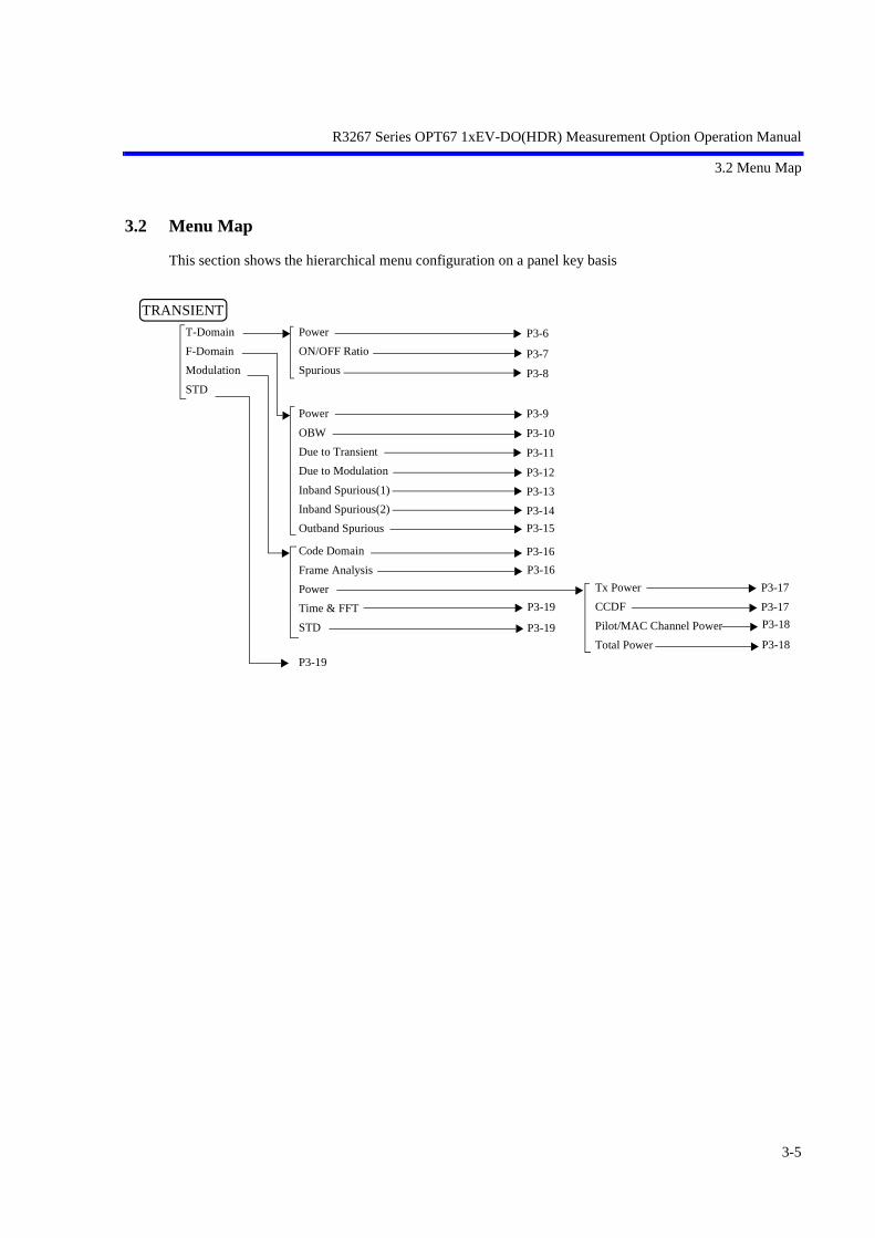
3.2 Menu Map
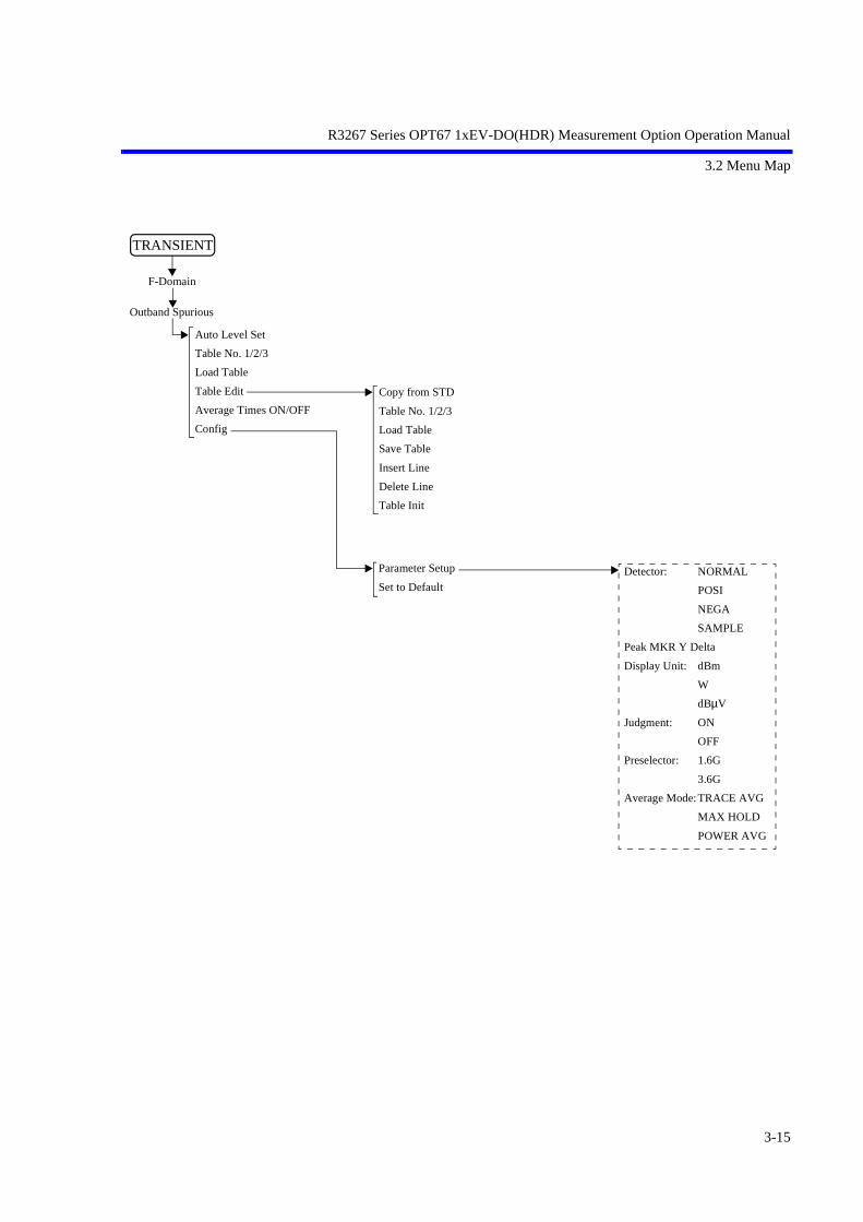
3.2 Menu Map
This section shows the hierarchical menu configuration on a panel key basis
TRANSIENT
T-Domain
F-Domain
Modulation
STD
Power
ON/OFF Ratio
Spurious
Code Domain
Frame Analysis
Power
Time & FFT
STD
P3-16
P3-6
P3-7
P3-8
P3-19
P3-19
Power
OBW
Due to Transient
Due to Modulation
Inband Spurious(1)
Inband Spurious(2)
Outband Spurious
P3-9
P3-10
P3-11
P3-12
P3-13
P3-15
Tx Power
CCDF
Pilot/MAC Channel Power
Total Power
P3-17
P3-17
P3-19
P3-14
P3-18
P3-18
P3-16
3-5
R3267 Series OPT67 1xEV-DO(HDR) Measurement Option Operation Manual
3.2 Menu Map
Trigger Source:FREE RUN
VIDEO
IF
EXT
Slope: +
-
Trigger Level
Trigger Position
Delay Time
Detector: NORMAL
POSI
NEGA
SAMPLE
Display Unit: dBm
W
dBµV
Template Couple to Power:
ON
OFF
Template Limit
Judgment: ON
OFF
Upper Limit
Lower Limit
Average Mode:TRACE AVG
MAX HOLD
POWER AVG
NUMERIC
Window ON/OFF
Set to STD
Window Position
Window Width
Parameter Setup
Set to STD
Auto Level Set
Trigger Setup
Window Setup
Template
Y Scale [dB/div] 10/5/2
Average Times ON/OFF
Config
Power
T-Domain
Template ON/OFF
Shift X
Shift Y
Template Edit Template UP/LOW
Copy from STD
Insert Line
Delete Line
Sort
Table Init
TRANSIENT
3-6

R3267 Series OPT67 1xEV-DO(HDR) Measurement Option Operation Manual
3.2 Menu Map
Auto Level Set
Trigger Setup
Window Setup
Y Scale [dB/div] 10/5/2
Average Times ON/OFF
Config
Trigger Source:FREE RUN
VIDEO
IF
EXT
Slope: +
-
Trigger Level
Trigger Position
Delay Time
Window ON/OFF
Set to STD
ON Position
ON Width
OFF Position
OFF Width
Detector: NORMAL
POSI
NEGA
SAMPLE
Display Unit: dBm
W
dBµV
Judgment: ON
OFF
Upper Limit
Average Mode:TRACE AVG
MAX HOLD
POWER AVG
NUMERIC
Parameter Setup
Set to STD
TRANSIENT
ON/OFF Ratio
T-Domain
3-7

R3267 Series OPT67 1xEV-DO(HDR) Measurement Option Operation Manual
3.2 Menu Map
Trigger Source:FREE RUN
IF
EXT
Slope: +
-
Trigger Level
Trigger Position
Delay Time
Detector: NORMAL
POSI
NEGA
SAMPLE
Result: PEAK
RMS
Peak MKR Y Delta
Multiplier
Display Unit: dBm
W
dBµV
Judgment: ON
OFF
Preselector: 1.6G
3.6G
Average Mode:TRACE AVG
MAX HOLD
POWER AVG
NUMERIC
Table No. 1/2/3
Load Table
Save Table
Insert Line
Delete Line
Table Init
Parameter Setup
Set to Default
Auto Level Set
Trigger Setup
Table No. 1/2/3
Load Table
Table Edit
Average Times ON/OFF
Config
Spurious
T-Domain
TRANSIENT
3-8

R3267 Series OPT67 1xEV-DO(HDR) Measurement Option Operation Manual
3.2 Menu Map
Detector: NORMAL
POSI
NEGA
SAMPLE
Gated Sweep: ON
OFF
Display Unit: dBm
W
dBµV
Judgment: ON
OFF
Upper Limit
Lower Limit
Average Mode:TRACE AVG
MAX HOLD
POWER AVG
NUMERIC
Window ON/OFF
Set to STD
Window Position
Window Width
Parameter Setup
Set to STD
Auto Level Set
Gate Setup
Window Setup
Y Scale [dB/div] 10/5/2
Average Times ON/OFF
Config
Power
F-Domain
Trigger Setup
Gate Source
Gate Setup
Gated Sweep ON/OFF
Detector
Trigger Source:FREE RUN
VIDEO
IF
EXT
Slope: +
-
Trigger Level
Trigger Position
Delay Time
Detector: NORMAL
POSI
NEGA
SAMPLE
Trigger
Ext Gate
Set to STD
Gate Position
Gate Width
TRANSIENT
3-9

R3267 Series OPT67 1xEV-DO(HDR) Measurement Option Operation Manual
3.2 Menu Map
Detector: NORMAL
POSI
NEGA
SAMPLE
Judgment: ON
OFF
Upper Limit
Lower Limit
Average Mode:TRACE AVG
MAX HOLD
POWER AVG
NUMERIC
Parameter Setup
Set to STD
Auto Level Set
OBW%
Average Times ON/OFF
Config
OBW
F-Domain
TRANSIENT
3-10

R3267 Series OPT67 1xEV-DO(HDR) Measurement Option Operation Manual
3.2 Menu Map
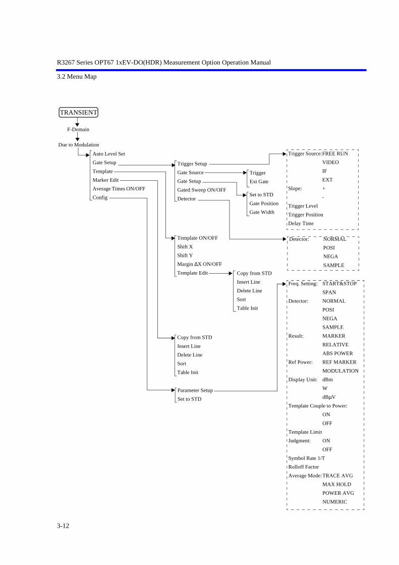
F-Domain
Freq. Setting: START&STOP
SPAN
Detector: NORMAL
POSI
NEGA
SAMPLE
Result: MARKER
RELATIVE
ABS POWER
Ref Power: REF MARKER
MODULATION
Display Unit: dBm
W
dBµV
Template Couple to Power:
ON
OFF
Template Limit
Judgment: ON
OFF
Symbol Rate 1/T
Rolloff Factor
Average Mode:TRACE AVG
MAX HOLD
POWER AVG
NUMERIC
Parameter Setup
Set to STD
Auto Level Set
Template
Marker Edit
Average Times ON/OFF
Config
Due to Transient
Template ON/OFF
Shift X
Shift Y
Margin ∆X ON/OFF
Template Edit Copy from STD
Insert Line
Delete Line
Sort
Table Init
Copy from STD
Insert Line
Delete Line
Sort
Table Init
TRANSIENT
3-11
R3267 Series OPT67 1xEV-DO(HDR) Measurement Option Operation Manual
3.2 Menu Map
F-Domain
Parameter Setup
Set to STD
Auto Level Set
Gate Setup
Template
Marker Edit
Average Times ON/OFF
Config
Due to Modulation
Template ON/OFF
Shift X
Shift Y
Margin ∆X ON/OFF
Template Edit Copy from STD
Insert Line
Delete Line
Sort
Table Init
Copy from STD
Insert Line
Delete Line
Sort
Table Init
Trigger Setup
Gate Source
Gate Setup
Gated Sweep ON/OFF
Detector
Trigger Source:FREE RUN
VIDEO
IF
EXT
Slope: +
-
Trigger Level
Trigger Position
Delay Time
Freq. Setting: START&STOP
SPAN
Detector: NORMAL
POSI
NEGA
SAMPLE
Result: MARKER
RELATIVE
ABS POWER
Ref Power: REF MARKER
MODULATION
Display Unit: dBm
W
dBµV
Template Couple to Power:
ON
OFF
Template Limit
Judgment: ON
OFF
Symbol Rate 1/T
Rolloff Factor
Average Mode:TRACE AVG
MAX HOLD
POWER AVG
NUMERIC
Detector: NORMAL
POSI
NEGA
SAMPLE
Trigger
Ext Gate
Set to STD
Gate Position
Gate Width
TRANSIENT
3-12

R3267 Series OPT67 1xEV-DO(HDR) Measurement Option Operation Manual
3.2 Menu Map
F-Domain
Parameter Setup
Set to STD
Auto Level Set
Template
Marker Edit
Average Times ON/OFF
Config
Inband Spurious(1)
Template ON/OFF
Shift X
Shift Y
Margin ∆X ON/OFF
Template Edit Copy from STD
Insert Line
Delete Line
Sort
Table Init
Copy from STD
Insert Line
Delete Line
Sort
Table Init
Freq. Setting: START&STOP
SPAN
Detector: NORMAL
POSI
NEGA
SAMPLE
Peak MKR Y Delta
Result: MARKER
RELATIVE
ABS POWER
Ref Power: REF MARKER
MODULATION
Display Unit: dBm
W
dBµV
Template Couple to Power:
ON
OFF
Template Limit
Judgment: ON
OFF
Average Mode:TRACE AVG
MAX HOLD
POWER AVG
TRANSIENT
3-13

R3267 Series OPT67 1xEV-DO(HDR) Measurement Option Operation Manual
3.2 Menu Map
F-Domain
Parameter Setup
Set to STD
Auto Level Set
Template
Marker Edit
Average Times ON/OFF
Config
Inband Spurious(2)
Template ON/OFF
Shift X
Shift Y
Margin ∆X ON/OFF
Template Edit Copy from STD
Insert Line
Delete Line
Sort
Table Init
Copy from STD
Insert Line
Delete Line
Sort
Table Init
Freq. Setting: START&STOP
SPAN
Detector: NORMAL
POSI
NEGA
SAMPLE
Peak MKR Y Delta
Result: MARKER
RELATIVE
ABS POWER
Ref Power: REF MARKER
MODULATION
Display Unit: dBm
W
dBµV
Template Couple to Power:
ON
OFF
Template Limit
Judgment: ON
OFF
Band Conversion:
ON
OFF
Integral Band
Start Offset
Stop Offset
Average Mode:POWER AVG
TRANSIENT
3-14
R3267 Series OPT67 1xEV-DO(HDR) Measurement Option Operation Manual
3.2 Menu Map
Detector: NORMAL
POSI
NEGA
SAMPLE
Peak MKR Y Delta
Display Unit: dBm
W
dBµV
Judgment: ON
OFF
Preselector: 1.6G
3.6G
Average Mode:TRACE AVG
MAX HOLD
POWER AVG
Copy from STD
Table No. 1/2/3
Load Table
Save Table
Insert Line
Delete Line
Table Init
Parameter Setup
Set to Default
Auto Level Set
Table No. 1/2/3
Load Table
Table Edit
Average Times ON/OFF
Config
Outband Spurious
F-Domain
TRANSIENT
3-15

R3267 Series OPT67 1xEV-DO(HDR) Measurement Option Operation Manual
3.2 Menu Map
TRANSIENT
Modulation
Code Domain
Complementary Filter Rolloff:
Equalizing Filter: ON/OFF
PN Offset:
MAC Threshold:
Trigger Source: INT/EXT/INTRVL(EXT)/INTRVL
EXT Trigger Slope: +/-
Auto Level Set
Graph Type
Parameter Setup
Modulation
TRANSIENT
MAC Code Domain
Data Code Domain
Pilot Constellation
Data Despread Constellation
Phase Error(Pilot)
Frame Analysis
Auto Level Set
Parameter Setup Complementary Filter Rolloff:
Equalizing Filter: ON/OFF
PN Offset:
MAC Threshold:
Trigger Source: INT/EXT/INTRVL(EXT)/INTRVL
EXT Trigger Slope: +/-
3-16

R3267 Series OPT67 1xEV-DO(HDR) Measurement Option Operation Manual
3.2 Menu Map
Tx Power
Modulation
Auto Level Set
Parameter Setup
Average Times ON/OFF
Power
Trigger Source : INT/EXT/INTRVL(EXT)/IF
EXT Trigger Slope : +/-
Trigger Level :
EXT Trigger Delay :
TRANSIENT
CCDF
Modulation
Auto Level Set
Scale Setup
Parameter Setup
Trace Write ON/OFF
Power
Trigger Mode : INT/EXT
Trigger Slope : +/-
Trigger Delay :
Meas Length :
X Scale Max :
X Scale Range :
Power Unit : RELATIVE/ABS POWER
TRANSIENT
3-17

R3267 Series OPT67 1xEV-DO(HDR) Measurement Option Operation Manual
3.2 Menu Map
Modulation
Auto Level Set
Template Entry
Y [dB/div] 10/5
Parameter Setup
Average Times ON/OFF
Power
TRANSIENT
Modulation
Power
TRANSIENT
Pilot/MAC Channel Power
USER Template
STD Template
Total Power
Auto Level Set
Template Entry
Parameter Setup
Average Times ON/OFF
PN Offset:
Bandpass Filter: ON/OFF
Trigger Source: INT/EXT/INTRVL(EXT)/INTRVL
EXT Trigger Slope: +/-
USER Template
STD Template
PN Offset:
Bandpass Filter: ON/OFF
Trigger Source: INT/EXT/INTRVL(EXT)/INTRVL
EXT Trigger Slope: +/-
3-18

R3267 Series OPT67 1xEV-DO(HDR) Measurement Option Operation Manual
3.2 Menu Map
Time & FFT
Auto Level Set
Select Type
Parameter Setup
Average Times ON/OFF
Modulation
Trigger Source : FREE RUN/IF/EXT
Trigger Slope : +/-
Trigger Level :
Trigger Delay :
Time & FFT
IQ Complex FFT
Ich Time & FFT
Qch Time & FFT
Ich & Qch Time
TRANSIENT
STD
DC CAL
Channel Setting
STD SetupCopy from STD
Edit Table 1 2 3
Edit Table 4 5 6
Edit Table 7 8 9
Modulation
TRANSIENT
Band Class :
Signal Type : CONTINUOUS/BURST
Offset Level :
Frequency Input : FREQUENCY/CHANNEL
Channel Setting : FORWARD/REVERSE
Input : RF/BASEBAND(I&Q)
Baseband Input : AC/DC
IQ Inverse : NORMAL/INVERSE
Cont Auto Level Set : ON/OFF
3-19
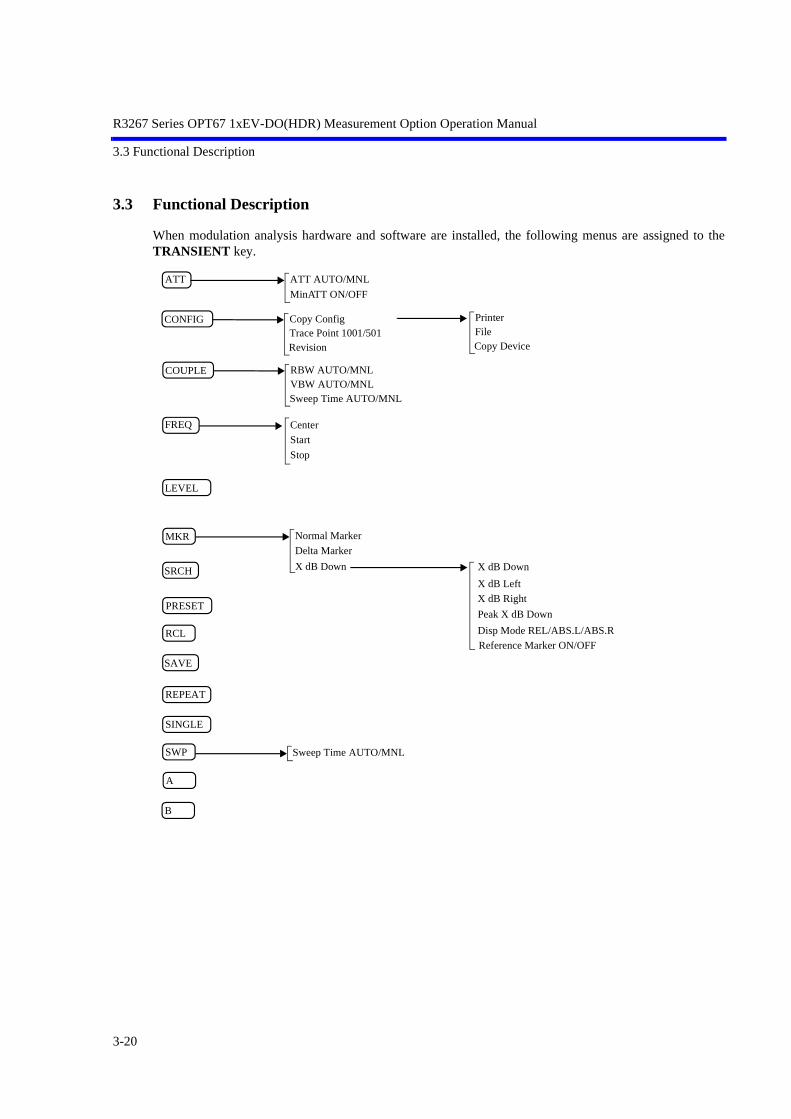
R3267 Series OPT67 1xEV-DO(HDR) Measurement Option Operation Manual
3.3 Functional Description
3.3 Functional Description
When modulation analysis hardware and software are installed, the following menus are assigned to theTRANSIENT key.
Sweep Time AUTO/MNL
ATT ATT AUTO/MNL
COUPLE RBW AUTO/MNL
FREQ
VBW AUTO/MNLSweep Time AUTO/MNL
Center
Start
Stop
LEVEL
PRESET
RCL
SAVE
SINGLE
MinATT ON/OFF
CONFIG Copy ConfigTrace Point 1001/501Revision
MKR
SWP
REPEAT
SRCH
Normal Marker
Delta Marker
PrinterFileCopy Device
X dB Down X dB Down
X dB Left
X dB Right
Peak X dB Down
Disp Mode REL/ABS.L/ABS.R
Reference Marker ON/OFF
A
B
3-20

R3267 Series OPT67 1xEV-DO(HDR) Measurement Option Operation Manual
3.3 Functional Description
3.3.1 Switching Communication Systems
This section describes how to switch the communication systems. The analyzer must be set to the SPAmode to switch between the communication systems.
NOTE: After the communication system has been switched, the parameters previously set for the former com-munication system will be cleared.If necessary, save the old parameters, before switching the communication system to another.
Switching communication systems
1. Press the POWER to enter the SPA mode.
2. Press CONFIG.
3. Press more 1/2.If there are other communication systems installed, with which this instrumentcan analyze, “Comm.System” is displayed in the soft menu.
4. Press Comm.System.Select the communication system you wish using the data knob, and press theknob (or ENTR).
Figure 3-1 Communication Systems Dialog Box
5. When the data knob (or ENTR) is pressed, the message “LOADING” is dis-played. After the message disappears, the switchover to another system is com-plete.
6. Press the TRANSIENT to confirm that the menu has been changed.
Saving set conditions
1. To save the parameters, press SHIFT and RCL.
2. Set the SAVE FILE number and press Save.
3-21

R3267 Series OPT67 1xEV-DO(HDR) Measurement Option Operation Manual
3.3 Functional Description
3.3.2 T-Domain
Carries out a measurement according to the standard using the zero span of the spectrum analyzer. Mea-surement items include power, ON/OFF ratio of a burst signal, and spurious measurements in the time do-main with a specified frequency.
In the T-Domain measurement, the setting for the RBW, VBW, Sweep Time, or Detector is saved whenexiting from each measurement and recalled when entering each measurement again. To return the settingto the value specified by the standard, press Config and Set to STD.
3.3.2.1 Power (T-Domain)
This is a function to measure power in the time domain (zero span).
There are two Pass/Fail judgment functions: a judgment function for the template and a judgment functionfor power.
NOTE: The RBW must be set wider than the modulation band.
Auto Level Set Sets the internal reference level to an optimum value in accor-dance with the measurement signal. The reference level is auto-matically adjusted when this key is pressed.
NOTE: The input signal level must be constant while Auto Level Set isbeing carried out.
Trigger Setup Sets a trigger.
Figure 3-2 Trigger Setup Dialog Box
Trigger Source Selects a trigger.
FREE RUN:Captures data using the internal measurement timing.
VIDEO: Captures the signal in sync with the VIDEO signal.
IF: Captures the signal in sync with the IF signal (approxi-mately 6 MHz band).
EXT: Captures the signal in sync with the external trigger sig-nal.
Slope Selects the edge when triggering.
+: Triggers at the leading edge.
-: Triggers at the trailing edge.
3-22

R3267 Series OPT67 1xEV-DO(HDR) Measurement Option Operation Manual
3.3 Functional Description
Trigger Level Sets the level to trigger.
Trigger Position Sets the trigger position where it is displayed on the screen.
Delay Time Sets a delay time from the time a trigger signal is detected to thetime the signal is captured.
NOTE: When Delay Time is a negative value, signals before the triggercan be captured.
Window Setup Sets the window used for power measurement.
Window ON/OFF Displays a window showing the range for power measurement.When OFF is set, the power measurement range covers all pointson the display screen.
Set to STD Sets the window specified by the communication standard.
Window Position Sets the position of the window.
Window Width Sets the width of the window.
NOTE: When the window is partially outside the display, an arrow isshown next to Pose, Width or both in the area indicating thewindow conditions.
Template Sets the template.For more information, refer to Section 5.1.1, “Template Setting inthe T-Domain Measuring Mode.”
Template ON/OFF Sets whether to display the template and to toggles the Pass/Failjudgment function on or off.
Shift X Sets the amount of template movement in the X-axis direction.
Shift Y Sets the amount of template movement in the Y-axis direction.
Template Edit Edits the template.
Template UP/LOW Selects the upper template or the lower template.
Copy from STD Initializes the template.
Insert Line Inserts a line.
Delete Line Deletes a line.
3-23

R3267 Series OPT67 1xEV-DO(HDR) Measurement Option Operation Manual
3.3 Functional Description
Sort Sorts template data in ascending order.
Table Init Initializes the table.
Y Scale [dB/div] 10/5/2 Switches the display screen scale to 10, 5 or 2 dB/div.
Average Times ON/OFF Sets the averaging count.For the method of average processing, refer to “Average Mode”in the Config → Parameter Setup.
Config
Parameter Setup Sets the method of measurement, edits the template, and so forth.
Figure 3-3 Parameter Setup Dialog Box
Detector NORMAL/POSI/NEGA/SAMPLE Sets the detector.
Display Unit dBm/W/dBµV Sets the display unit.
Template Couple to Power Displays the template that is connected to the measured power.
ON: Displays the template that is connected to the measuredpower.On the template edit screen, set the template level to theportion linked with the power value set to 0 dB.
OFF: Displays the template regarding the Y-axis value editedby the template as an absolute value.
Template Limit If the absolute value of the template is smaller than this valuewhen Template Couple to Power is set to ON, clip the template atthis value.
Judgment Sets ON/OFF for Pass/Fail judgments.
Upper Limit Sets the upper limit value of power.
Lower Limit Sets the lower limit value of power.
Average Mode Selects the processing method when Average Times is set to ON.
3-24

R3267 Series OPT67 1xEV-DO(HDR) Measurement Option Operation Manual
3.3 Functional Description
TRACE AVG:Calculates arithmetic average of the measured data(Log data) in the mode LOG.
MAX HOLD:Displays the maximum value within the average countsof the swept waveforms.
POWER AVG:Converts the measured data (Log data) to the linear datato take the root mean square value.
NUMERIC:Converts the measured data (Log data) to the linear datato take the root mean square value. Using POWER AVG displays the average waveforms,using NUMERIC displays the swept waveforms andtakes an average of the measurement results only.
Set to STD Returns measurement parameters to the values specified by thecommunication standard.
3.3.2.2 ON/OFF Ratio
Measures the power during the burst-on period and the one during the burst-off period, and calculate theratio of the powers. Captures the signal with a trigger and calculates the ratio in reference to the burst on and burst off periods(the former is defined as the period immediately before the trigger point; the latter, immediately after thetrigger point).
Auto Level Set Sets the internal reference level to an optimum value in accor-dance with the measurement signal. The reference level is auto-matically adjusted when this key is pressed.
NOTE: The signal level must remain constant while Auto Level Set isbeing carried out.
Trigger Setup Sets a trigger.
Figure 3-4 Trigger Setup Dialog Box
Trigger Source Selects a trigger.
FREE RUN:Captures data using the internal measurement timing.
VIDEO: Captures the signal in sync with the VIDEO signal.
3-25

R3267 Series OPT67 1xEV-DO(HDR) Measurement Option Operation Manual
3.3 Functional Description
IF: Captures the signal in sync with the IF signal (approxi-mately 6 MHz band).
EXT: Captures the signal in sync with the external trigger sig-nal.
Slope Selects the edge when triggering.
+: Triggers at the leading edge.
-: Triggers at the trailing edge.
Trigger Level Sets the level to trigger.
Trigger Position Sets where the trigger position is displayed on the screen.
Delay Time Sets a delay time from the time a trigger signal is detected to thetime the signal is captured.
NOTE: When Delay Time is a negative value, signals before the triggercan be captured.
Window Setup Sets the burst ON and OFF periods.
Window ON/OFF Displays a window showing the range for power measurement.
Set to STD Sets the value that is specified by or complies with the communi-cation standard.
ON Position Sets the desired position during the burst-on period.
ON Width Sets the desired width during the burst-on period.
OFF Position Sets the position during the burst-off period.
OFF Width Sets the width during the burst-off period.
NOTE: When the window is partially outside the display, an arrow isshown next to Pose, Width or both in the area indicating thewindow conditions.
Y Scale [dB/div] 10/5/2 Selects the display screen scale to 10, 5 or 2 dB/div.
Average Times ON/OFF Sets the averaging count.For the method of average processing, refer to “Average Mode”in the Config → Parameter Setup.
Config
3-26

R3267 Series OPT67 1xEV-DO(HDR) Measurement Option Operation Manual
3.3 Functional Description
Parameter Setup Sets measurement parameters and so on.
Figure 3-5 Parameter Setup Dialog Box
Detector NORMAL/POSI/NEGA/SAMPLE Selects the detector.
Display Unit dBm/W/dBµV Sets the display unit of power.
NOTE: The ON/OFF ratio is displayed in units of dB (fixed).
Judgment Sets ON/OFF of the Pass/Fail judgment for the ON/OFF ratio.
Upper Limit Enters the upper limit value.
Average Mode Selects the processing method when Average Times is set to ON.
TRACE AVG:Calculates arithmetic average of the measured data(Log data) in the mode LOG.
MAX HOLD:Displays the maximum value within the average countsof the swept waveforms.
POWER AVG:Converts the measured data (Log data) to the linear datato take the root mean square value.
NUMERIC:Converts the measured data (Log data) to the linear datato take the root mean square value. Using POWER AVG displays the average waveforms,using NUMERIC displays the swept waveforms andtakes an average of the measurement results only.
Set to STD Sets measurement parameters to the values specified by the com-munication standard.
3-27

R3267 Series OPT67 1xEV-DO(HDR) Measurement Option Operation Manual
3.3 Functional Description
3.3.2.3 Spurious (T-Domain)
This is a function to measure power (or peak power) according to the frequency specified in the table bysweeping in the zero span mode.
Auto Level Set Sets the internal reference level to an optimum value in accor-dance with the measurement signal. The reference level is auto-matically adjusted when this key is pressed.
NOTE: The signal level must be constant while Auto Level Set is beingcarried out.
Trigger Setup Sets a trigger.
Figure 3-6 Trigger Setup Dialog Box
Trigger Source Selects a trigger.
FREE RUN:Captures data using the internal measurement timing.
IF: Captures the signal in sync with the IF signal (approxi-mately 6 MHz band).
EXT: Captures the signal in sync with the external trigger sig-nal.
Slope Selects the edge when triggering.
+: Triggers at the leading edge.
-: Triggers at the trailing edge.
Trigger Level Sets the level to trigger.
Trigger Position Sets where the trigger position is displayed on the screen.
Delay Time Sets a delay time from the time a trigger signal is detected to thetime the signal is captured.
NOTE: When Delay Time is a negative value, signals before the triggercan be captured.
Table No. 1/2/3 Selects the measurement table.
3-28

R3267 Series OPT67 1xEV-DO(HDR) Measurement Option Operation Manual
3.3 Functional Description
Load Table Loads the measurement table.
Table Edit Edits the measurement table.
Table No. 1/2/3 Selects the table to be edited.
Load Table Loads the measurement table.
Save Table Saves the measurement table.
Insert Line Inserts additional frequency data before the selected frequencynumber.
Delete Line Deletes the selected line.
Table Init Initializes the table.
Average Times ON/OFF Sets the averaging count. For the method of average processing, refer to “Average Mode”in the Config → Parameter Setup.
Config
Parameter Setup Sets measurement conditions and so on.
Figure 3-7 Parameter Setup Dialog Box
Detector NORMAL/POSI/NEGA/SAMPLE Sets the detector.
Result PEAK/RMS Sets whether to display the result using average power or peakpower.
Peak MKR Y Delta Sets the Y delta of the peak marker.
Multiplier Multiplies the measurement result by the set value, then displaysthe resultant value.
Display Unit dBm/W/dBµV Sets the display units.
3-29

R3267 Series OPT67 1xEV-DO(HDR) Measurement Option Operation Manual
3.3 Functional Description
Judgment Sets ON/OFF of the Pass/Fail judgment for the limit value.
Preselector Sets the preselector.
NOTE: This menu is displayed on R3267 only.
1.6G: Used to measure harmonics of more than 1.6 GHz orspurious signals when the carrier frequency is lowerthan 1.6 GHz.
3.6G: Used to set this parameter for cases other than thatabove.
Average Mode Selects the processing method when Average Times is set to ON.
TRACE AVG:Calculates arithmetic average of the measured data(Log data) in the mode LOG.
MAX HOLD:Displays the maximum value within the average countsof the swept waveforms.
POWER AVG:Converts the measured data (Log data) to the linear datato take the root mean square value.
NUMERIC:Converts the measured data (Log data) to the linear datato take the root mean square value. Using POWER AVG displays the average waveforms,using NUMERIC displays the swept waveforms andtakes an average of the measurement results only.
Set to Default Returns the set value to the default.
3-30

R3267 Series OPT67 1xEV-DO(HDR) Measurement Option Operation Manual
3.3 Functional Description
3.3.3 F-Domain
Carries out a measurement according to the communication standard using the spectrum analyzer’s sweepmeasurement method. Measurement items include power, occupied bandwidth, ACP Due To Transient,ACP Due to Modulation, Inband Spurious, and Outband Spurious measurements is the frequency domain.
In F-Domain measurement, the setting for the RBW, VBW, Sweep Time, or Detector is saved when exit-ing each measurement and recalled when entering each measurement again. To return the setting to thevalue specified by the standard, press Config and Set to STD.
3.3.3.1 Power (F-Domain)
This is a function to measure power in the frequency domain using the spectrum analyzer.
Auto Level Set Sets the internal reference level to an optimum value in accor-dance with the measurement signal. The reference level is auto-matically adjusted when this key is pressed.
NOTE: The signal level must be constant while Auto Level Set is beingcarried out.
Gate Setup Sets the gated sweep.This setting is required when the input signal is a bursted signaland Sample Detector is used.
Trigger Setup Sets a trigger.
Figure 3-8 Trigger Setup Dialog Box
Trigger Source Selects a trigger.
FREE RUN:Captures data using the internal measurement timing.
VIDEO: Captures the signal in sync with the VIDEO signal.
IF: Captures the signal in sync with the IF signal (approxi-mately 6 MHz band).
EXT: Captures the signal in sync with the external trigger sig-nal.
Slope Selects the edge when triggering.
+: Triggers at the leading edge.
-: Triggers at the trailing edge.
Trigger Level Sets the level to trigger.
3-31
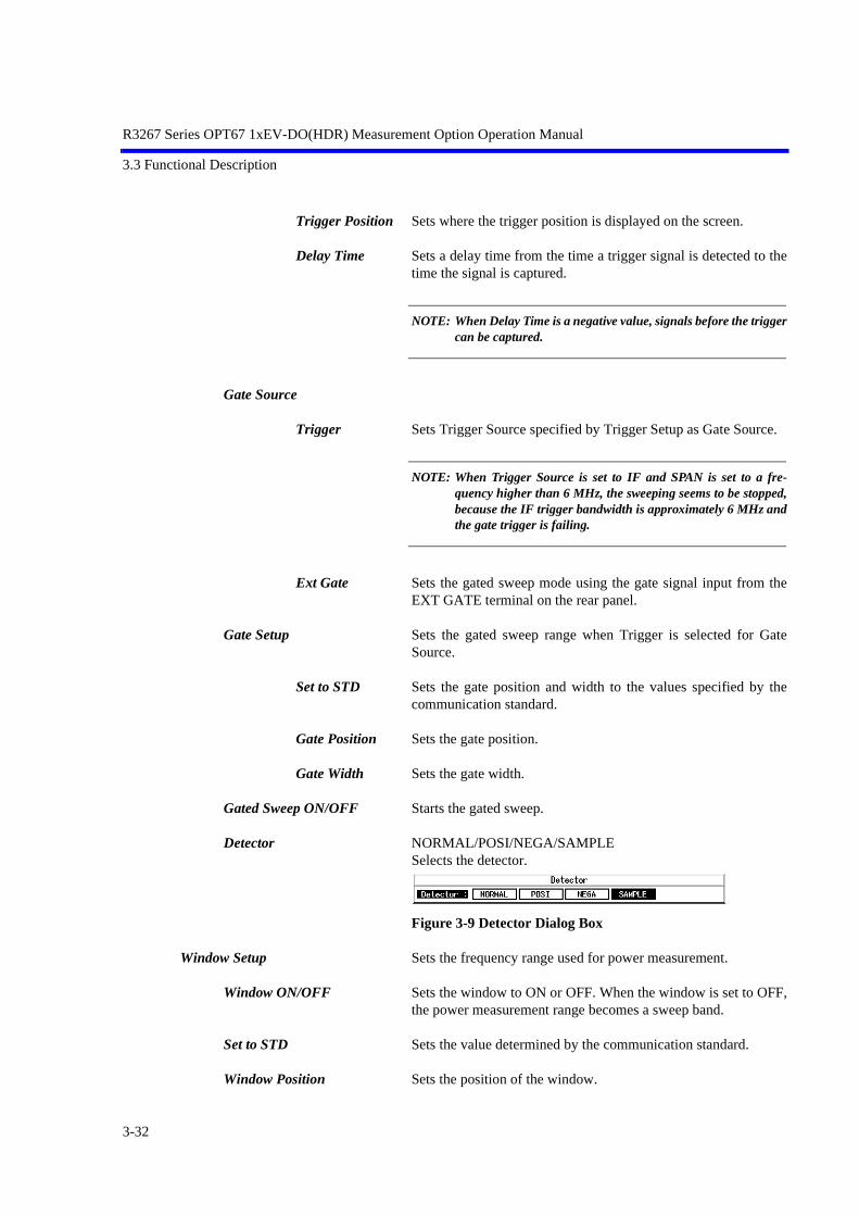
R3267 Series OPT67 1xEV-DO(HDR) Measurement Option Operation Manual
3.3 Functional Description
Trigger Position Sets where the trigger position is displayed on the screen.
Delay Time Sets a delay time from the time a trigger signal is detected to thetime the signal is captured.
NOTE: When Delay Time is a negative value, signals before the triggercan be captured.
Gate Source
Trigger Sets Trigger Source specified by Trigger Setup as Gate Source.
NOTE: When Trigger Source is set to IF and SPAN is set to a fre-quency higher than 6 MHz, the sweeping seems to be stopped,because the IF trigger bandwidth is approximately 6 MHz andthe gate trigger is failing.
Ext Gate Sets the gated sweep mode using the gate signal input from theEXT GATE terminal on the rear panel.
Gate Setup Sets the gated sweep range when Trigger is selected for GateSource.
Set to STD Sets the gate position and width to the values specified by thecommunication standard.
Gate Position Sets the gate position.
Gate Width Sets the gate width.
Gated Sweep ON/OFF Starts the gated sweep.
Detector NORMAL/POSI/NEGA/SAMPLE Selects the detector.
Figure 3-9 Detector Dialog Box
Window Setup Sets the frequency range used for power measurement.
Window ON/OFF Sets the window to ON or OFF. When the window is set to OFF,the power measurement range becomes a sweep band.
Set to STD Sets the value determined by the communication standard.
Window Position Sets the position of the window.
3-32

R3267 Series OPT67 1xEV-DO(HDR) Measurement Option Operation Manual
3.3 Functional Description
Window Width Sets the width of the window.
NOTE: When the window is partially outside the display, an arrow isshown next to Pose, Width or both in the area indicating thewindow conditions.
Y Scale [dB/div] 10/5/2 Sets the display scale.
Average Times ON/OFF Sets the averaging count.For the method of average processing, refer to “Average Mode”in the Config → Parameter Setup.
Config
Parameter Setup Sets measurement conditions and so on.
Figure 3-10 Parameter Setup Dialog Box
Detector NORMAL/POSI/NEGA/SAMPLE Selects the detector.
Gated Sweep Sets the gated sweep to ON or OFF.
Display Unit dBm/W/dBµV Selects the display unit.
Judgment Sets ON/OFF of the Pass/Fail judgment for measured power.
Upper Limit Sets the upper limit for Pass/Fail judgment.
Lower Limit Sets the lower limit for Pass/Fail judgment.
Average Mode selects the processing method when Average Times is set to ON.
TRACE AVG:Calculates arithmetic average of the measured data(Log data) in the mode LOG.
MAX HOLD:Displays the maximum value within the average countsof the swept waveforms.
3-33
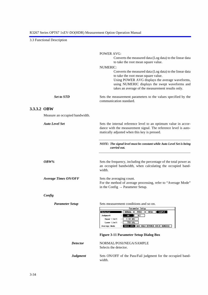
R3267 Series OPT67 1xEV-DO(HDR) Measurement Option Operation Manual
3.3 Functional Description
POWER AVG:Converts the measured data (Log data) to the linear datato take the root mean square value.
NUMERIC:Converts the measured data (Log data) to the linear datato take the root mean square value. Using POWER AVG displays the average waveforms,using NUMERIC displays the swept waveforms andtakes an average of the measurement results only.
Set to STD Sets the measurement parameters to the values specified by thecommunication standard.
3.3.3.2 OBW
Measure an occupied bandwidth.
Auto Level Set Sets the internal reference level to an optimum value in accor-dance with the measurement signal. The reference level is auto-matically adjusted when this key is pressed.
NOTE: The signal level must be constant while Auto Level Set is beingcarried out.
OBW% Sets the frequency, including the percentage of the total power asan occupied bandwidth, when calculating the occupied band-width.
Average Times ON/OFF Sets the averaging count.For the method of average processing, refer to “Average Mode”in the Config → Parameter Setup.
Config
Parameter Setup Sets measurement conditions and so on.
Figure 3-11 Parameter Setup Dialog Box
Detector NORMAL/POSI/NEGA/SAMPLE Selects the detector.
Judgment Sets ON/OFF of the Pass/Fail judgment for the occupied band-width.
3-34

R3267 Series OPT67 1xEV-DO(HDR) Measurement Option Operation Manual
3.3 Functional Description
Upper Limit Sets the upper limit for Pass/Fail judgment.
Lower Limit Sets the lower limit for Pass/Fail judgment.
Average Mode selects the processing method when Average Times is set to ON.
TRACE AVG:Calculates OBW based on the waveforms, which weregenerated as a result of arithmetic average of the mea-sured data (Log data) in the log mode.
MAX HOLD:Calculates OBW based on the waveform with the max-imum value within the average counts of the measureddata.
POWER AVG:Calculates OBW based on the waveforms, which werecalculated as a result of the conversion of the measureddata (Log data) to the linear data to take the room meansquare.
NUMERIC:Calculates OBW by sweep and calculates arithmeticaverage to display the result. The displayed waveformsare not averaged.
Set to STD Sets the measurement parameters to the values specified by thecommunication standard.
3.3.3.3 Due to Transient
This is a function to measure the spectrum, including the rise and fall times of the burst.
Auto Level Set Sets the internal reference level to an optimum value in accor-dance with the measurement signal. The reference level is auto-matically adjusted when this key is pressed.
NOTE: The signal level must be constant while Auto Level Set is beingcarried out.
Template Sets and edits the template.For more information, refer to Section 5.1.2, “Template Setting inthe F-Domain Measuring Mode.”
Template ON/OFF Sets ON/OFF of the template display.When Template is set to ON, the Pass/Fail judgment for the tem-plate is displayed under the sweep screen.
Shift X Shifts the set template in the frequency direction (X-axis).
Shift Y Shifts the set template in the level direction (Y-axis).
3-35

R3267 Series OPT67 1xEV-DO(HDR) Measurement Option Operation Manual
3.3 Functional Description
Margin ∆X ON/OFF Magnifies the template in the X-axis direction with a set templatefrequency 0 as the center.
Template Edit Opens the template edit menu.
Copy from STD Copies the template defined in the communication standard.
Insert Line Inserts a line before the selected line.
Delete Line Deletes the selected line.
Sort Sorts the tables in order of frequency.
Table Init Initializes the table.
Marker Edit Sets the measurement frequency (frequency offset) and measure-ment band.For more information, refer to Section 5.2.1, “Marker Edit Func-tion.”
Copy from STD Sets to the parameters specified by the communication standard.
Insert Line Inserts a line before the selected line.
Delete Line Deletes the selected line.
Sort Sorts data in order of frequency.
Table Init Initializes the table.
Average Times ON/OFF Sets the averaging count.For the method of average processing, refer to “Average Mode”in the Config → Parameter Setup.
Config
Parameter Setup Sets measurement conditions and so on.
Figure 3-12 Parameter Setup Dialog Box
3-36

R3267 Series OPT67 1xEV-DO(HDR) Measurement Option Operation Manual
3.3 Functional Description
Freq. Setting START&STOP/SPANSelects the measurement mode.
Detector NORMAL/POSI/NEGA/SAMPLESelects the detector.
Result Specifies how to display the result.For more information, refer to Section 5.2.2, “Measurement re-sults Using Due to Modulation, Due to Transient and Inband Spu-rious Modes.”
MARKER:Displays the marker read value. The position of the markeris set by Marker Edit.
RELATIVE:Displays the marker read value using a relative value.
ABS POWER:Converts the value displayed by RELATIVE into the abso-lute value using carrier power and displays it.
Ref Power When RELATIVE is selected for Result, this selects which rela-tive value to use to display the marker read value.
REF MARKER:Displays a relative value to Ref Marker set by Marker Edit.
MODULATION:Displays a relative value to the measurement result of Txpower in Modulation.
Display Unit dBm/W/dBµVSpecifies the unit of the result displayed.
NOTE: When RELATIVE is selected for Result, the unit is dB.
Template Couple to Power Sets whether to raise or lower the template with the power set byRef Power.
Template Limit If the absolute value of the template is smaller than this valuewhen Template Couple to Power is set to ON, clip the template atthis value.
Judgment Used to make the Pass/fail judgment for the limit value set byMarker edit. The Pass/Fail judgment result is displayed under thedisplay screen together with the marker list.
Symbol Rate 1/T Sets the symbol rate of the Root Nyquist filter.
Rolloff Factor Sets the roll-off of the Root Nyquist filter.
3-37

R3267 Series OPT67 1xEV-DO(HDR) Measurement Option Operation Manual
3.3 Functional Description
Average Mode Selects the processing method when Average Times is set to ON.
TRACE AVG:Calculates arithmetic average of the measured data(Log data) in the mode LOG.
MAX HOLD:Displays the maximum value within the average countsof the swept waveforms.
POWER AVG:Converts the measured data (Log data) to the linear datato take the root mean square value.
NUMERIC:Converts the measured data (Log data) to the linear datato take the root mean square value. Using POWER AVG displays the average waveforms,using NUMERIC displays the swept waveforms andtakes an average of the measurement results only.
Set to STD Returns the measurement parameters to the values specified bythe standard.
3.3.3.4 Due to Modulation
Measure the modulation spectrum excluding the rise and fall of the burst.
Auto Level Set Sets the internal reference level to an optimum value in accor-dance with the measurement signal. The reference level is auto-matically adjusted when this key is pressed.
NOTE: The signal level must be constant while Auto Level Set is beingcarried out.
Gate Setup Sets the gated sweep.
Trigger Setup Sets a trigger.
Figure 3-13 Trigger Setup Dialog Box
Trigger Source Selects a trigger.
FREE RUN:Captures data using the internal measurement timing.
VIDEO: Captures the signal in sync with the VIDEO signal.
3-38

R3267 Series OPT67 1xEV-DO(HDR) Measurement Option Operation Manual
3.3 Functional Description
IF: Captures the signal in sync with the IF signal (approxi-mately 6 MHz band).
EXT: Captures the signal in sync with the external trigger sig-nal.
Slope Selects the edge when triggering.
+: Triggers at the leading edge.
-: Triggers at the trailing edge.
Trigger Level Sets the level to trigger.
Trigger Position Sets where the trigger position is displayed on the screen.
Delay Time Sets a delay time from the time a trigger signal is detected to thetime the signal is captured.
NOTE: When Delay Time is a negative value, signals before the triggercan be captured.
Gate Source
Trigger Sets Trigger Source specified by Trigger Setup as Gate Source.
NOTE: When Trigger Source is set to IF and SPAN is set to a fre-quency higher than 6 MHz, the sweeping seems to be stopped,because the IF trigger bandwidth is approximately 6 MHz andthe gate trigger is failing.
Ext Gate Performs the gated sweep using the gate signal input from theEXT Gate terminal on the rear panel.
Gate Setup Sets the gated sweep range when Trigger is selected for GateSource.
Set to STD Sets the gate position and width to the values specified by thecommunication standard.
Gate Position Sets the gate position.
Gate Width Sets the gate width.
Gated Sweep ON/OFF Starts the gated sweep.
3-39

R3267 Series OPT67 1xEV-DO(HDR) Measurement Option Operation Manual
3.3 Functional Description
Detector NORMAL/POSI/NEGA/SAMPLE Selects the detector.
Figure 3-14 Detector Dialog Box
Template Sets and edits the template.For more information, refer to Section 5.1.2, “Template Setting inthe F-Domain Measuring Mode.”
Template ON/OFF Sets the template display to ON or OFF.When Template is set to ON, the Pass/Fail judgment for the tem-plate is displayed under the sweep screen.
Shift X Shifts the set template in the frequency direction (X-axis).
Shift Y Shifts the set template in the level direction (Y-axis).
Margin ∆X ON/OFF Magnifies the template in the X-axis direction with a set templatefrequency 0 as the center.
Template Edit
Copy from STD Copies the template defined in the communication standard.
Insert Line Inserts a line before the selected line.
Delete Line Deletes the selected line.
Sort Sorts the tables in frequency order.
Table Init Initializes the table.
Marker Edit For more information, refer to Section 5.2.1, “Marker Edit Func-tion.”
Copy from STD Sets to the parameters specified by the communication standard.
Insert Line Inserts a line before the selected line.
Delete Line Deletes the selected line.
Sort Sorts data in order of frequency.
Table Init Initializes the table.
Average Times ON/OFF Sets the averaging count.For the method of average processing, refer to “Average Mode”in the Config → Parameter Setup.
3-40
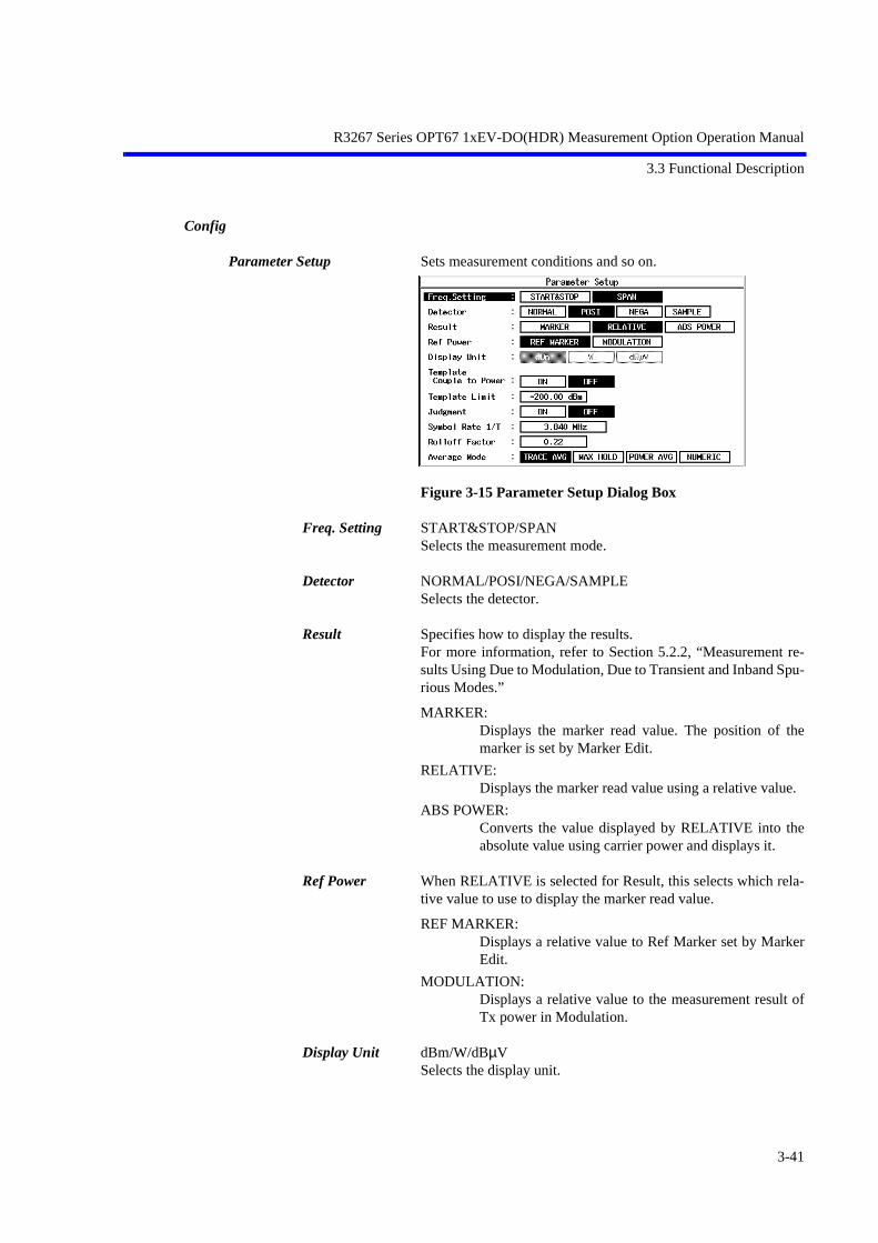
R3267 Series OPT67 1xEV-DO(HDR) Measurement Option Operation Manual
3.3 Functional Description
Config
Parameter Setup Sets measurement conditions and so on.
Figure 3-15 Parameter Setup Dialog Box
Freq. Setting START&STOP/SPAN Selects the measurement mode.
Detector NORMAL/POSI/NEGA/SAMPLE Selects the detector.
Result Specifies how to display the results.For more information, refer to Section 5.2.2, “Measurement re-sults Using Due to Modulation, Due to Transient and Inband Spu-rious Modes.”
MARKER:Displays the marker read value. The position of themarker is set by Marker Edit.
RELATIVE:Displays the marker read value using a relative value.
ABS POWER:Converts the value displayed by RELATIVE into theabsolute value using carrier power and displays it.
Ref Power When RELATIVE is selected for Result, this selects which rela-tive value to use to display the marker read value.
REF MARKER:Displays a relative value to Ref Marker set by MarkerEdit.
MODULATION:Displays a relative value to the measurement result ofTx power in Modulation.
Display Unit dBm/W/dBµV Selects the display unit.
3-41

R3267 Series OPT67 1xEV-DO(HDR) Measurement Option Operation Manual
3.3 Functional Description
NOTE: When RELATIVE is selected for Result, the unit is dB.
Template Couple to Power Sets whether or not to raise or lower the template with the powerset by Ref Power.
Template Limit If the absolute value of the template is smaller than this valuewhen Template Couple to Power is set to ON, clip the template atthis value.
Judgment Used to make the Pass/Fail judgment for the limit value set byMarker edit. The Pass/Fail judgment result is displayed under thedisplay screen together with the marker list.
Symbol Rate 1/T Sets the symbol rate of the Root Nyquist filter.
Rolloff Factor Sets the roll-off of the Root Nyquist filter.
Average Mode Selects the processing method when Average Times is set to ON.
TRACE AVG:Calculates arithmetic average of the measured data(Log data) in the mode LOG.
MAX HOLD:Displays the maximum value within the average countsof the swept waveforms.
POWER AVG:Converts the measured data (Log data) to the linear datato take the root mean square value.
NUMERIC:Converts the measured data (Log data) to the linear datato take the root mean square value. Using POWER AVG displays the average waveforms,using NUMERIC displays the swept waveforms andtakes an average of the measurement results only.
Set to STD Returns the measurement parameters to the values specified bythe standard.
3-42

R3267 Series OPT67 1xEV-DO(HDR) Measurement Option Operation Manual
3.3 Functional Description
3.3.3.5 Inband Spurious(1)
This is a function to search for a peak by sweeping the set frequency.
Auto Level Set Sets the internal reference level to an optimum value in accor-dance with the measurement signal. The reference level is auto-matically adjusted when this key is pressed.
NOTE: The signal level must be constant while Auto Level Set is beingcarried out.
Template For more information, refer to Section 5.1.2, “Template Setting inthe F-Domain Measuring Mode.”
Template ON/OFF Sets the template display to ON or OFF.When Template is set to ON, the Pass/Fail judgment for the tem-plate is displayed under the sweep screen.
Shift X Shifts the set template in the frequency direction (X-axis).
Shift Y Shifts the set template in the level direction (Y-axis).
Margin ∆X ON/OFF Magnifies the template in the X-axis direction with a set templatefrequency 0 as the center.
Template Edit For more information, refer to Section 5.1.2, “Template Setting inthe F-Domain Measuring Mode.”
Copy from STD Copies the template defined in the communication standard.
Insert Line Inserts a line before the selected line.
Delete Line Deletes the selected line.
Sort Sorts the tables in frequency order.
Table Init Initializes the table.
Marker Edit For more information, refer to Section 5.2.1, “Marker Edit Func-tion.”
Copy from STD Sets to the parameters specified by the communication standard.
Insert Line Inserts a line before the selected line.
Delete Line Deletes the selected line.
Sort Sorts data in order of frequency.
3-43
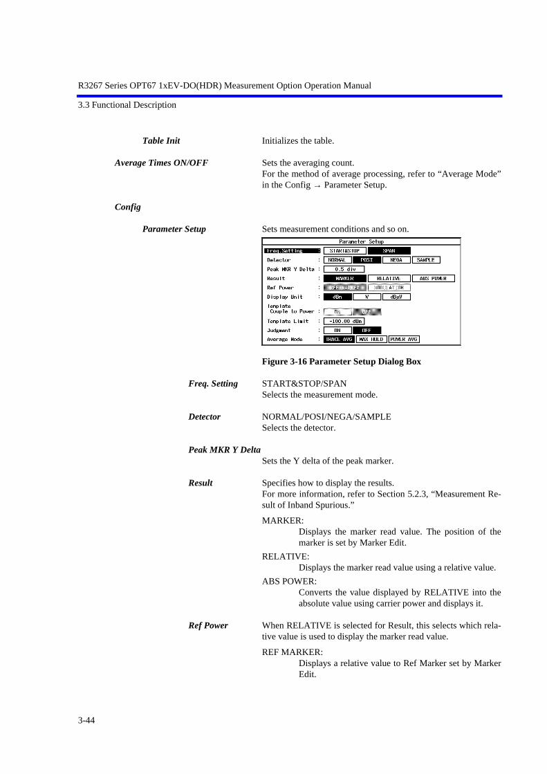
R3267 Series OPT67 1xEV-DO(HDR) Measurement Option Operation Manual
3.3 Functional Description
Table Init Initializes the table.
Average Times ON/OFF Sets the averaging count.For the method of average processing, refer to “Average Mode”in the Config → Parameter Setup.
Config
Parameter Setup Sets measurement conditions and so on.
Figure 3-16 Parameter Setup Dialog Box
Freq. Setting START&STOP/SPAN Selects the measurement mode.
Detector NORMAL/POSI/NEGA/SAMPLE Selects the detector.
Peak MKR Y Delta Sets the Y delta of the peak marker.
Result Specifies how to display the results.For more information, refer to Section 5.2.3, “Measurement Re-sult of Inband Spurious.”
MARKER:Displays the marker read value. The position of themarker is set by Marker Edit.
RELATIVE:Displays the marker read value using a relative value.
ABS POWER:Converts the value displayed by RELATIVE into theabsolute value using carrier power and displays it.
Ref Power When RELATIVE is selected for Result, this selects which rela-tive value is used to display the marker read value.
REF MARKER:Displays a relative value to Ref Marker set by MarkerEdit.
3-44
R3267 Series OPT67 1xEV-DO(HDR) Measurement Option Operation Manual
3.3 Functional Description
MODULATION:Displays a relative value to the measurement result ofTx power in Modulation.
Display Unit dBm/W/dBµVSelects the display unit.
NOTE: When RELATIVE is selected for Result, the unit is dB.
Template Couple to PowerSets whether or not to raise or lower the template with the powerset by Ref Power.
Template Limit If the absolute value of the template is smaller than this valuewhen Template Couple to Power is set to ON, clip the template atthis value.
Judgment Used to make the Pass/Fail judgment for the limit value set byMarker edit. The Pass/Fail judgment result is displayed under thedisplay screen together with the marker list.
Average Mode Selects the processing method when Average Times is set to ON.
TRACE AVG:Calculates arithmetic average of the measured data(Log data) in the mode LOG.
MAX HOLD:Displays the maximum value within the average countsof the swept waveforms.
POWER AVG:Converts the measured data (Log data) to the linear datato take the root mean square value.
Set to STD Returns the measurement parameters to the values specified bythe standard.
3-45

R3267 Series OPT67 1xEV-DO(HDR) Measurement Option Operation Manual
3.3 Functional Description
3.3.3.6 Inband Spurious(2)
Converts resolution bandwidth (RBW) to search spurious signal.When the spurious is swept with broadband RBW near the career frequency, the career signal cannot beseparated, which makes the spurious search impossible. In this situation, the sweep with narrow RBW isrequired to calculate the bandwidth in order to search spurious signal.
Auto Level Set Sets the internal reference level to an optimum value in accor-dance with the measurement signal. The reference level is auto-matically adjusted when this key is pressed.
NOTE: The signal level must be constant while Auto Level Set is beingcarried out.
Template For more information, refer to Section 5.1.2, “Template Setting inthe F-Domain Measuring Mode.”
Template ON/OFF Sets the template display to ON or OFF.When Template is set to ON, the Pass/Fail judgment for the tem-plate is displayed under the sweep screen.
Shift X Shifts the set template in the frequency direction (X-axis).
Shift Y Shifts the set template in the level direction (Y-axis).
Margin ∆X ON/OFF Magnifies the template in the X-axis direction with a set templatefrequency 0 as the center.
Template Edit For more information, refer to Section 5.1.2, “Template Setting inthe F-Domain Measuring Mode.”
Copy from STD Copies the template specified by the communication standard.
Insert Line Inserts a line before the selected line.
Delete Line Deletes the selected line.
Sort Sorts the tables in frequency order.
Table Init Initializes the table.
Marker Edit For more information, refer to Section 5.2.1, “Marker Edit Func-tion.”
Copy from STD Sets the measurement parameters specified by the communicationstandard.
Insert Line Inserts a line before the selected line.
3-46
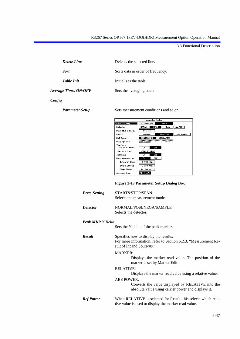
R3267 Series OPT67 1xEV-DO(HDR) Measurement Option Operation Manual
3.3 Functional Description
Delete Line Deletes the selected line.
Sort Sorts data in order of frequency.
Table Init Initializes the table.
Average Times ON/OFF Sets the averaging count.
Config
Parameter Setup Sets measurement conditions and so on.
Figure 3-17 Parameter Setup Dialog Box
Freq. Setting START&STOP/SPAN Selects the measurement mode.
Detector NORMAL/POSI/NEGA/SAMPLE Selects the detector.
Peak MKR Y Delta Sets the Y delta of the peak marker.
Result Specifies how to display the results.For more information, refer to Section 5.2.3, “Measurement Re-sult of Inband Spurious.”
MARKER:Displays the marker read value. The position of themarker is set by Marker Edit.
RELATIVE:Displays the marker read value using a relative value.
ABS POWER:Converts the value displayed by RELATIVE into theabsolute value using carrier power and displays it.
Ref Power When RELATIVE is selected for Result, this selects which rela-tive value is used to display the marker read value.
3-47

R3267 Series OPT67 1xEV-DO(HDR) Measurement Option Operation Manual
3.3 Functional Description
REF MARKER:Displays a relative value to Ref Marker set by MarkerEdit.
MODULATION:Displays a relative value to the measurement result ofTx power in Modulation.
Display Unit dBm/W/dBµVSelects the display unit.
NOTE: When RELATIVE is selected for Result, the unit is dB.
Template Couple to PowerSets whether or not to raise or lower the template with the powerset by Ref Power.
Template Limit If the absolute value of the template is smaller than this valuewhen Template Couple to Power is set to ON, clip the template atthis value.
Judgment Used to make the Pass/Fail judgment for the limit value set byMarker edit. The Pass/Fail judgment result is displayed under thedisplay screen together with the marker list.
Band Conversion This function is used to calculate the resolution bandwidth usingthe swept waveforms.
ON: Calculates resolution bandwidth using the measured da-ta.
OFF: Does not calculate resolution bandwidth using the mea-sured data.
Integral Band Sets resolution bandwidth that conducts the bandwidth calcula-tion.
Start Offset Sets the starting frequency that conducts the bandwidth calcula-tion, using the offset frequency from the center frequency.
Stop Offset Sets the ending frequency that conducts the band calculation, us-ing the offset frequency from the center frequency.
NOTE: Even when the Start Offset and Stop Offset values have beenset beyond the frequency display range, data is calculatedwithin the frequency display range.
Average Mode Sets the processing when Average Times is set to ON.POWER AVG is fixed.
3-48

R3267 Series OPT67 1xEV-DO(HDR) Measurement Option Operation Manual
3.3 Functional Description
POWER AVG:Converts the measured data (Log data) to the linear datato take the root mean square
Set to STD Returns the measurement parameters to the values specified bythe standard.
3.3.3.7 Outband Spurious
This is a function to search for a peak by sweeping the frequency according to the table.
Auto Level Set Sets the internal reference level to an optimum value in accor-dance with the measurement signal. The reference level is auto-matically adjusted when this key is pressed.
NOTE: The signal level must be constant while Auto Level Set is beingcarried out.
Table No. 1/2/3 Selects the table number.
Load Table Loads the table.
Table Edit Edits the table.
Copy from STD Sets measurement parameters to the communication standard.
Table No. 1/2/3 Selects the table number.
Load Table Loads the table.
Save Table Saves the table.
Insert Line Inserts a line before the selected line.
Delete Line Deletes the selected line.
Table Init Initializes the table.
Average Times ON/OFF Sets the averaging count.For the method of average processing, refer to “Average Mode”in the Config → Parameter Setup.
3-49

R3267 Series OPT67 1xEV-DO(HDR) Measurement Option Operation Manual
3.3 Functional Description
Config
Parameter Setup Sets measurement conditions and so on.
Figure 3-18 Parameter Setup Dialog Box
Detector NORMAL/POSI/NEGA/SAMPLESets the detector.
Peak MKR Y DeltaSets the Y delta of a peak marker.
Display Unit dBm/W/dBµVSets the display unit.
Judgment Makes the Pass/Fail judgment using the limit values set by TableEdit.
Preselector Sets the preselector.
NOTE: This menu is displayed on R3267 only.
1.6G: The preselector is activated for frequencies of 1.6 GHzor higher only.If the carrier frequency is less than 1.6 GHz, selectingthis item allows you to measure harmonics of 1.6 GHzor higher.
3.6G: Used to set this parameter for cases other than thatabove.
Average Mode Selects the processing method when Average Times is set to ON.
TRACE AVG:Calculates arithmetic average of the measured data(Log data) in the mode LOG.
MAX HOLD:Displays the maximum value within the average countsof the swept waveforms.
POWER AVG:Converts the measured data (Log data) to the linear datato take the root mean square value.
Set to Default Returns the set value to the default.
3-50

R3267 Series OPT67 1xEV-DO(HDR) Measurement Option Operation Manual
3.3 Functional Description
3.3.4 Modulation
The modulation analysis is performed.
3.3.4.1 Code Domain
The code domain analysis of the HDR Access Network output signal is performed.
Auto Level Set Automatically adjusts the reference level.
NOTE: While the auto level set is in process, maintain the level of theinput signal.
Graph Type Changes Graph Types.
Figure 3-19 Graph Type Setting Examples
MAC Code Domain Selecting MAC Code Domain displays the code domain of MACchannels.The horizontal axis indicates the Walsh Code Numbers.The vertical axis indicates logarithmic values (10 × Log10 ρ [dB])of ρ.ρMAC, real (i) (Code Domain Power of MAC Channels) is dis-played in yellow.ρMAC, imag (i) (Code Domain Power of MAC Channels) is dis-played in green.These values indicate 8-slot code domain values.(N = 16 : 16 half slots)
Data Code Domain Selecting Data Code Domain displays the data code domain with-out preambles.The horizontal axis indicates the Walsh Code Numbers. The vertical axis indicates logarithmic values (10 × Log10 ρ [dB])of ρ.ρData, real (i) (Code Domain Power of Traffic or Control Channel)is displayed in yellow.ρData, imag (i) (Code Domain Power of Traffic or Control Channel)is displayed in green.These values indicate 2-slot data code domain values.(N = 4 : 4 half slots)
3-51

R3267 Series OPT67 1xEV-DO(HDR) Measurement Option Operation Manual
3.3 Functional Description
Pilot Constellation Selecting Pilot Constellation displays the constellation of the PilotChannel.Each chip point is displayed in a yellow dot and these points areconnected by green lines.This indicates a 10-slot constellation of the Pilot Channel.(N = 20 : 20 half slots)The marker indicates a half slot number as well as a chip numberfor the half slot in order.
Data Despread Constellation Selecting Data Despread Constellation displays the constellationafter the despred with the data Walsh Codes without preambles.Symbol data is despread using the Walsh Codes. These symbolpoints are displayed in yellow dots and are connected by greenlines.This indicates a 2-slot data constellation.(N = 4 : 4 half slots)One symbol data (16 chips) is despread using 16 Walsh Codes.Accordingly, 16 dots are displayed in order of the Walsh Codenumber. Likewise, 16 dots are displayed for the next symbol in or-der of the Walsh Code numbers.A symbol for the preamble indicates 0.The marker indicates a symbol number as well as the Walsh Codenumber for the symbol in order.
Phase Error(Pilot) Selecting Phase Error (Pilot) displays phase errors of the PilotChannel.This indicates 10-slot phase errors for each chip point of the PilotChannel.(N = 20 : 20 half slots)The marker indicates a half slot number as well as the chip num-ber for the half slot in order.
Parameter Setup Sets the measurement parameters.
Figure 3-20 Parameter Setting Examples
Complementary Filter Rolloff Sets the Rolloff coefficient to decide the characteristics of a com-plementary filter. The setting range: 0.05 to 0.2
Equalizing Filter Sets ON or OFF for the equalizing filter. When the output of the access network passes through the equal-izing filter, sets to the ON position.
3-52
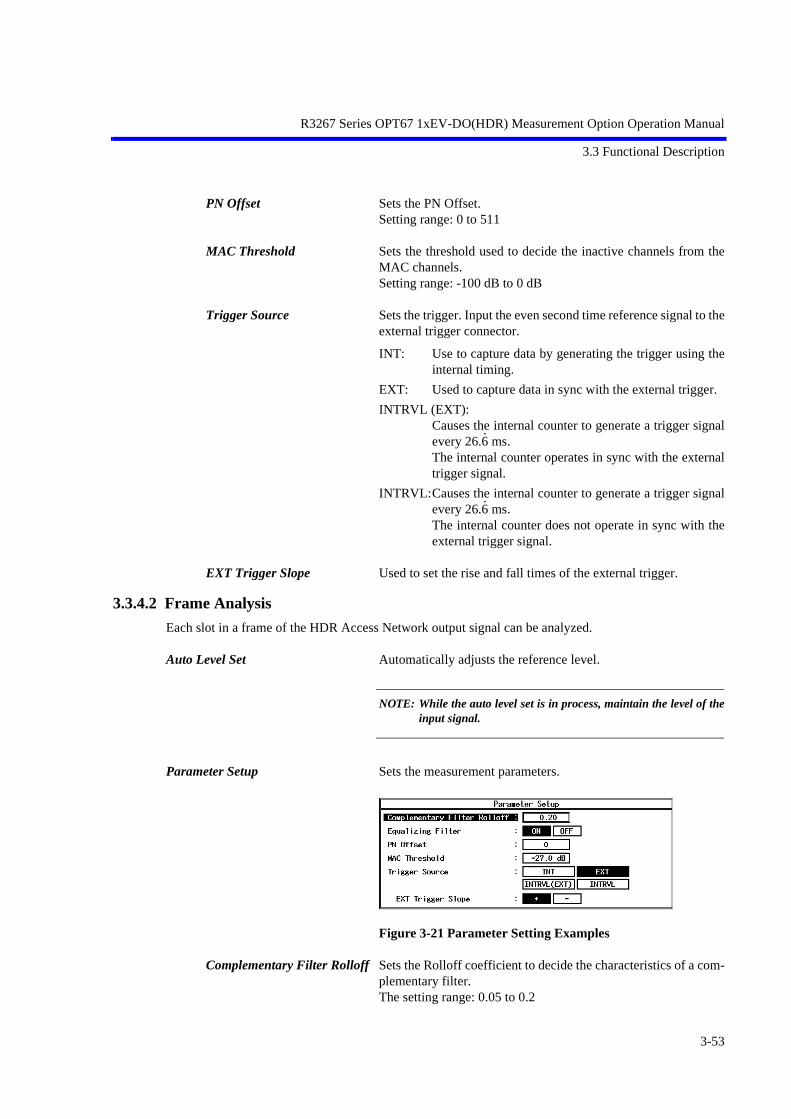
R3267 Series OPT67 1xEV-DO(HDR) Measurement Option Operation Manual
3.3 Functional Description
PN Offset Sets the PN Offset. Setting range: 0 to 511
MAC Threshold Sets the threshold used to decide the inactive channels from theMAC channels.Setting range: -100 dB to 0 dB
Trigger Source Sets the trigger. Input the even second time reference signal to theexternal trigger connector.
INT: Use to capture data by generating the trigger using theinternal timing.
EXT: Used to capture data in sync with the external trigger.
INTRVL (EXT):Causes the internal counter to generate a trigger signalevery 26.6
•
ms.The internal counter operates in sync with the externaltrigger signal.
INTRVL:Causes the internal counter to generate a trigger signalevery 26.6
•
ms.The internal counter does not operate in sync with theexternal trigger signal.
EXT Trigger Slope Used to set the rise and fall times of the external trigger.
3.3.4.2 Frame Analysis
Each slot in a frame of the HDR Access Network output signal can be analyzed.
Auto Level Set Automatically adjusts the reference level.
NOTE: While the auto level set is in process, maintain the level of theinput signal.
Parameter Setup Sets the measurement parameters.
Figure 3-21 Parameter Setting Examples
Complementary Filter Rolloff Sets the Rolloff coefficient to decide the characteristics of a com-plementary filter. The setting range: 0.05 to 0.2
3-53
R3267 Series OPT67 1xEV-DO(HDR) Measurement Option Operation Manual
3.3 Functional Description
Equalizing Filter Sets ON or OFF for the equalizing filter. When the output of the access network passes through the equal-izing filter, sets to the ON position.
PN Offset Sets the PN Offset. Setting range: 0 to 511
MAC Threshold Sets the threshold used to decide the inactive channels from theMAC channels.Setting range: -100 dB to 0 dB
Trigger Source Sets the trigger. Input the even second time reference signal to theexternal trigger connector.
INT: Use to capture data by generating the trigger using theinternal timing.
EXT: Used to capture data in sync with the external trigger.
INTRVL (EXT):Causes the internal counter to generate a trigger signalevery 26.6
•
ms.The internal counter operates in sync with the externaltrigger signal.
INTRVL:Causes the internal counter to generate a trigger signalevery 26.6
•
ms.The internal counter does not operate in sync with theexternal trigger signal.
EXT Trigger Slope Used to set the rise and fall times of the external trigger.
3-54

R3267 Series OPT67 1xEV-DO(HDR) Measurement Option Operation Manual
3.3 Functional Description
3.3.4.3 Power
3.3.4.3.1 Tx PowerMeasures the power of a modulation signal.
Auto Level Set Sets an internal reference level (REF LEVEL) to the optimumvalue in agreement with the measurement signal.
NOTE: The level of an input signal must be constant during the execu-tion of Auto Level Set.
Parameter Setup Sets measurement conditions and so on.
Figure 3-22 Parameter Setup Dialog Box
Trigger Source Selects a trigger signal.
INT: Sweeps in synchronization with an internal trigger sig-nal.
EXT: Sweeps in synchronization with an external trigger sig-nal, which is input from the Ext Trigger connector onthe rear panel.
INTRVL (EXT):The built-in counter generates triggers every 26.6
•
milli-seconds. The built-in counter is in sync with the exter-nal trigger.
IF: Captures data in synchronization with the IF signal (theleading edge of the burst).
EXT Trigger Slope Changes the polarity of the trigger slope.
+: Starts sweeping at the leading edge of the trigger.
-: Starts sweeping at the trailing edge of the trigger.
Trigger Level Sets the trigger level.
3-55

R3267 Series OPT67 1xEV-DO(HDR) Measurement Option Operation Manual
3.3 Functional Description
EXT Trigger Delay Corrects the delay time when the signal (the head of PN) lags be-hind the external trigger.
NOTE: When a negative value is set, a signal before the trigger can beobserved.
Average Times ON/OFF Selects an averaging process.
ON: Activates the number of times of averaging and per-forms averaging the specified number of times.
OFF: Does not perform an averaging process.
NOTE: Peak Factor obtained as a result of a power measurement cal-culates the peak power and average power within the measure-ment counts.
3.3.4.3.2 CCDFThe CCDF (Complementary Cumulative Distribution Function), average power and peak factor of thesignal under measurement can be measured.
Auto Level Set Automatically adjusts the reference level.
Scale Setup Switches between measurement results.
Figure 3-23 Scale Setup Dialog Box
X Scale Max Sets the maximum value along the horizontal axis between -20dB(m) and 70 dB(m) in steps of 10 dB.
X Scale Range Sets the display range along the horizontal axis between 10 dB and 50 dB in steps of 10 dB.
Power Unit Sets the unit to be displayed.
RELATIVE:Displays the power relative to the average power.
ABS POWER:Displays the power in absolute value.
NOTE: If the signal power is 70 dBm or more, the power cannot bedisplayed in an absolute value.
3-56

R3267 Series OPT67 1xEV-DO(HDR) Measurement Option Operation Manual
3.3 Functional Description
Parameter Setup Sets the parameters used for measurements.
Figure 3-24 Parameter Setup Dialog Box
Trigger Mode Selects the timing for retrieving data.
INT: Captures data using the internal trigger.
EXT: Captures data using the external trigger.
Trigger Slope Toggles the external trigger slope between + and -.
+: Captures data at the rising edge.
-: Captures data at the falling edge.
Trigger Delay Delays the external trigger timing.Can be set between -250 µs and 250 µs in steps of 1 µs.
Meas Length The number of measurement samples is set.Can be set between 10k sample and 100M sample in steps of 10ksample.
Trace Write ON/OFF Sets whether or not the waveform is held.
ON: Holds the waveform.
OFF: Does not hold the waveform.
3.3.4.3.3 Pilot/MAC Channel PowerIdle Slot signal power of the HDR Access Network output can be measured.
Auto Level Set Automatically adjusts the reference level.
NOTE: While the auto level set is in process, maintain the level of theinput signal.
Template Entry Displays the template setting menu.
USER Template Selects USER Template (which can be set by a user).Values from -50 dB to 10 dB can be entered for Y0, Y1, and Y2.
STD Template Selects STD (standard) Template.Y0 indicates the lower limit value for the burst-on.Y1 indicates the upper limit value for the burst-on.Y2 indicates the upper limit value for the burst-off.
Y [dB/div] 10/5 Switches the vertical axis scale between 5 dB/div and 10 dB/div.
3-57

R3267 Series OPT67 1xEV-DO(HDR) Measurement Option Operation Manual
3.3 Functional Description
Parameter Setup Sets the measurement parameters.
Figure 3-25 Parameter Setting Examples
PN Offset Sets the PN Offset. Setting range: 0 to 511
Bandpass Filter Sets Bandpass Filter ON or OFF.When disturbing waves exist next to the bandwidth to be mea-sured, set Bandpass Filter to on.Pass a band-pass filter with a bandwidth of ±625 kHz that deviatesfrom the carrier frequency.
Trigger Source Sets the trigger. Input the even second time reference signal to theexternal trigger connector.
INT: Use to capture data by generating the trigger using theinternal timing.
EXT: Used to capture data in sync with the external trigger.
INTRVL (EXT):Causes the internal counter to generate a trigger signalevery 26.6
•
ms.The internal counter operates in sync with the externaltrigger signal.
INTRVL:Causes the internal counter to generate a trigger signalevery 26.6
•
ms.The internal counter does not operate in sync with theexternal trigger signal.
EXT Trigger Slope Used to set the rise and fall times of the external trigger.
Average Times ON/OFF Sets the averaging count.When ON is set, up to 512 can be entered.
3-58

R3267 Series OPT67 1xEV-DO(HDR) Measurement Option Operation Manual
3.3 Functional Description
3.3.4.3.4 Total PowerActive Slot signal power of the HDR Access Network output can be measured.
Auto Level Set Automatically adjusts the reference level.
NOTE: While the auto level set is in process, maintain the level of theinput signal.
Template Entry Displays the template setting menu.
USER Template Selects USER Template (which can be set by a user).Values from -50 dB to 10 dB can be entered for Y0 and Y1.
STD Template Selects STD (standard) template.Y0 indicates the lower limit value.Y1 indicates the upper limit value.
Parameter Setup Sets the measurement parameters.
Figure 3-26 Parameter Setting Examples
PN Offset Sets the PN Offset. Setting range: 0 to 511
Bandpass Filter Sets Bandpass Filter ON or OFF.When disturbing waves exist next to the bandwidth to be mea-sured, set Bandpass Filter to on.Pass a band-pass filter with a bandwidth of ± 625 kHz that devi-ates from the carrier frequency.
Trigger Source Sets the trigger. Input the even second time reference signal to theexternal trigger connector.
INT: Use to capture data by generating the trigger using theinternal timing.
EXT: Used to capture data in sync with the external trigger.
INTRVL (EXT):Causes the internal counter to generate a trigger signalevery 26.6
•
ms.The internal counter operates in sync with the externaltrigger signal.
3-59

R3267 Series OPT67 1xEV-DO(HDR) Measurement Option Operation Manual
3.3 Functional Description
INTRVL:Causes the internal counter to generate a trigger signalevery 26.6
•
ms.The internal counter does not operate in sync with theexternal trigger signal.
EXT Trigger Slope Used to set the rise and fall times of the external trigger.
Average Times ON/OFF Sets the averaging count.When ON is set, up to 512 can be entered.
3.3.4.4 Time & FFT
Displays a time-domain IF signal or FFT trace to confirm the input signal.
Auto Level Set Sets the internal reference level to an optimum value in accor-dance with the measurement signal. The reference level is auto-matically adjusted when this key is pressed.
NOTE: The signal level must stay constant while Auto Level Set isbeing carried out.
Select Type Selects the graph to be displayed.
Figure 3-27 Select Type Dialog Box
Parameter Setup
Figure 3-28 Parameter Setup Dialog Box
Trigger Source Sets the trigger signal.
FREE RUN:Captures data using the internal measurement timing.
IF: Captures the signal in sync with the IF signal (the lead-ing edge of the burst).
EXT: Captures the signal in sync with the external trigger sig-nal.
3-60

R3267 Series OPT67 1xEV-DO(HDR) Measurement Option Operation Manual
3.3 Functional Description
NOTE: The external trigger signal is input to the EXT TRIG connectoron the rear panel.
Trigger Slope Selects the polarity (leading or trailing edge) of a trigger signal.
Trigger Level Sets the trigger level.
Trigger Delay Sets a time period between the trigger and the data being captured.
Average Times ON/OFF Sets the averaging count.
3.3.4.5 STD
Sets parameters used for measurement and relationship between the channel number and frequency.
DC CAL Compensates for direct current components inside the circuit.
Channel Setting Sets the relationship between the channel number and frequency.
Copy from STD Sets the relationship between the channel number and frequencyspecified by the communication standard.
Edit Table 1 2 3 Displays tables 1 through 3.
Edit Table 4 5 6 Displays tables 4 through 6.
Edit Table 7 8 9 Displays tables 7 through 9.
STD Setup Sets the parameters for measurement.
Figure 3-29 STD Measurement Parameter Set Dialog Box
Band Class Selects the frequency bandwidth of the signal to be measured. It is used to calculate the frequency from the channel number.
3-61

R3267 Series OPT67 1xEV-DO(HDR) Measurement Option Operation Manual
3.3 Functional Description
Signal Type Sets whether or not the measuring signal is a burst.
CONTINUOUS: Select when measured signal is a Non-idleslot signal.
BURST: Select when measured signal is an idle slot. For the F-Domain Power measurement, thegate sweep is set as a default.
Offset Level The offset value of the reference level can be set in the range of±100 dB.
Frequency Input Sets the input method of the center frequency value to the measur-ing instrument.
FREQUENCY: Input by the frequency value.
CHANNEL: Input by the channel number.
Channel Setting Select a link for the channel settings table
FORWARD: Sets the channel number of the forward link.
REVERSE: Sets the channel number of the reverse link.
NOTE: Only the link for the channel settings table can be selected. Nomeasurement is available for the reverse link.
Input Sets the signal path for the input signal.
RF: Sets to the RF input path.
BASEBAND (I&Q): Sets to the IQ input path. The amplitude range for the input signal. 0.25 VP-P to 0.9 VP-P (± 0.47 V or less).
NOTE: Tx Power indicates the relative power, if the BASEBAND isentered.
Baseband Input
AC: Allows you to select AC coupling.
DC: Allows you to select DC coupling.
IQ Inverse Selects the inverse of the input signal phase.
NORMAL: Q signal code does not inverse
INVERSE: Q signal inverses
3-62
R3267 Series OPT67 1xEV-DO(HDR) Measurement Option Operation Manual
3.3 Functional Description
Cont Auto Level Set Sets whether or not the auto ranging is used for the signal input.
ON: Auto range for every measurement is used.
OFF: No auto range is used.
NOTE: The setting of the Cont Auto Level Set is valid when the entryis for RF selection, Code Domain, Frame Analysis, Tx Power,CCDF, Pilot/MAC Channel Power, or Total Power. For the ref-erence level adjustment, use the Auto Level Set of the soft key.
3-63

R3267 Series OPT67 1xEV-DO(HDR) Measurement Option Operation Manual
4 REMOTE CONTROL
4 REMOTE CONTROL
4.1 GPIB Command Index
This GPIB command index can be used as the index for Chapter 4.
GPIB Command Pages GPIB Command Pages
*CLS ........................................................ 4-49*ESE ........................................................ 4-49*ESR ........................................................ 4-49*IDN ........................................................ 4-49*RST ........................................................ 4-49*SRE ........................................................ 4-49*STB ........................................................ 4-49. ................................................................ 4-480 to 9 ........................................................ 4-48AA............................................................ 4-9AD............................................................ 4-49ALS OFF.................................................. 4-15ALS ON ................................................... 4-15AS ............................................................ 4-10AT ............................................................ 4-9ATMIN .................................................... 4-9ATMIN OFF ............................................ 4-9ATMIN ON.............................................. 4-9AUTOLVL............................................... 4-38, 4-42,
4-43, 4-44, 4-45, 4-46
AUTOWFL.............................................. 4-16BA............................................................ 4-10BBINPUT AC.......................................... 4-15BBINPUT DC.......................................... 4-15BNDCLS 0............................................... 4-13BNDCLS 1............................................... 4-13BNDCLS 2............................................... 4-13BNDCLS 3............................................... 4-13BNDCLS 4............................................... 4-13BNDCLS 5............................................... 4-13BNDCLS 6............................................... 4-13BNDCLS 7............................................... 4-13BNDCLS 8............................................... 4-13BNDCLS 9............................................... 4-13C2CCDF .................................................. 4-44C2CCDFMK............................................ 4-44C2CCDFMLEN ....................................... 4-44C2CCDFTRC OFF .................................. 4-44C2CCDFTRC ON.................................... 4-44C2CCDFTRG EXT.................................. 4-44
4-1
C2CCDFTRG INT................................... 4-44C2CCDFTRGDLY .................................. 4-44C2CCDFTRGSLP FALL ........................ 4-44C2CCDFTRGSLP RISE.......................... 4-44C2CCDFUNIT ABS ................................ 4-44C2CCDFUNIT REL ................................ 4-44C2CCDFXMAX ...................................... 4-44C2CCDFXRNG....................................... 4-44CAVGAT................................................. 4-17CAVGCHP .............................................. 4-24CAVGOBW............................................. 4-25CAVGRAT .............................................. 4-19CAVGSPR............................................... 4-33CCHPOW ................................................ 4-25CDCFERR ............................................... 4-39CDEQFLT OFF ....................................... 4-38CDEQFLT ON......................................... 4-38CDFROF.................................................. 4-38CDGTYP DATCD................................... 4-38CDGTYP DDCON .................................. 4-38CDGTYP MACCD.................................. 4-38CDGTYP PHAERR................................. 4-38CDGTYP PILCON.................................. 4-38CDMACTHRSH...................................... 4-38CDMAXCDP........................................... 4-39CDMEAS................................................. 4-39CDMINCDP ............................................ 4-39CDMK ..................................................... 4-39CDMKCHIP ............................................ 4-40CDMKGPHCHIP .................................... 4-41CDMKGPHI ............................................ 4-41CDMKGPHMACIDX ............................. 4-41CDMKGPHPHAERR.............................. 4-41CDMKGPHQ........................................... 4-41CDMKGPHRHODIM ............................. 4-41CDMKGPHRHODRE............................. 4-40CDMKGPHRHOMIM............................. 4-40CDMKGPHRHOMRE ............................ 4-40CDMKGPHSYM..................................... 4-41CDMKGPHWNUM ................................ 4-40CDMKI .................................................... 4-40

R3267 Series OPT67 1xEV-DO(HDR) Measurement Option Operation Manual
4.1 GPIB Command Index
CDMKMACIDX ..................................... 4-39CDMKPHAERR...................................... 4-40CDMKQ................................................... 4-40CDMKRHODIM ..................................... 4-39CDMKRHODRE..................................... 4-39CDMKRHOMIM..................................... 4-39CDMKRHOMRE .................................... 4-39CDMKSYM............................................. 4-40CDMKWNUM ........................................ 4-39CDMODTYP ........................................... 4-39CDPKINACT........................................... 4-39CDPKINACTL ........................................ 4-39CDPNOFS ............................................... 4-38CDPNOFSR............................................. 4-39CDPRCHIP.............................................. 4-39CDPTAERR............................................. 4-39CDRHO1 ................................................. 4-39CDRHO2 ................................................. 4-39CDRHOP ................................................. 4-39CDTRG EXT ........................................... 4-38CDTRG INT ............................................ 4-38CDTRG INTRVL1 .................................. 4-38CDTRG INTRVL2 .................................. 4-38CDTRGSLP FALL .................................. 4-38CDTRGSLP RISE ................................... 4-38CF............................................................. 4-10CH............................................................ 4-13CHEDFR1................................................ 4-13CHEDFR2................................................ 4-13CHEDFR3................................................ 4-13CHEDFR4................................................ 4-13CHEDFR5................................................ 4-13CHEDFR6................................................ 4-13CHEDFR7................................................ 4-13CHEDFR8................................................ 4-13CHEDFR9................................................ 4-13CHEDRV1 ............................................... 4-14CHEDRV2 ............................................... 4-14CHEDRV3 ............................................... 4-14CHEDRV4 ............................................... 4-14CHEDRV5 ............................................... 4-14CHEDRV6 ............................................... 4-14CHEDRV7 ............................................... 4-14CHEDRV8 ............................................... 4-14CHEDRV9 ............................................... 4-14CHSET FWD........................................... 4-13CHSET REV............................................ 4-13CHSETSTD ............................................. 4-14CHTBL1 DSBL ....................................... 4-14CHTBL1 ENBL....................................... 4-14CHTBL2 DSBL ....................................... 4-14
4-2
CHTBL2 ENBL....................................... 4-14CHTBL3 DSBL ....................................... 4-14CHTBL3 ENBL....................................... 4-14CHTBL4 DSBL ....................................... 4-14CHTBL4 ENBL....................................... 4-14CHTBL5 DSBL ....................................... 4-14CHTBL5 ENBL....................................... 4-14CHTBL6 DSBL ....................................... 4-14CHTBL6 ENBL....................................... 4-14CHTBL7 DSBL ....................................... 4-14CHTBL7 ENBL....................................... 4-14CHTBL8 DSBL ....................................... 4-14CHTBL8 ENBL....................................... 4-14CHTBL9 DSBL ....................................... 4-14CHTBL9 ENBL....................................... 4-14CINBMAX............................................... 4-34CINBSPR................................................. 4-34CLDC....................................................... 4-15COBW ..................................................... 4-26COBWCP................................................. 4-29COBWDET NEG .................................... 4-26COBWDET NRM.................................... 4-26COBWDET POS ..................................... 4-26COBWDET SMP..................................... 4-26COBWPER .............................................. 4-25COMMSYS CDMA2000 ........................ 4-9CPWDIV P10DB..................................... 4-24CPWDIV P5DB....................................... 4-24CPWDX................................................... 4-24CPWLX ................................................... 4-24DB............................................................ 4-48DC0.......................................................... 4-11DC1.......................................................... 4-11DC2.......................................................... 4-11DEL.......................................................... 4-12DEL REG_nn........................................... 4-12DELSTBL................................................ 4-21DL0 .......................................................... 4-49DL1 .......................................................... 4-49DL2 .......................................................... 4-49DL3 .......................................................... 4-49DL4 .......................................................... 4-49DTMAUTOLVL...................................... 4-29DTMAVG................................................ 4-30DTMAVGCNT........................................ 4-30DTMAVGMD MAX ............................... 4-31DTMAVGMD NUMERIC ...................... 4-31DTMAVGMD POWER .......................... 4-31DTMAVGMD TRACE ........................... 4-31DTMDET NEG........................................ 4-31DTMDET NRM....................................... 4-31

R3267 Series OPT67 1xEV-DO(HDR) Measurement Option Operation Manual
4.1 GPIB Command Index
DTMDET POS ........................................ 4-31DTMDET SMP........................................ 4-31DTMFRMD ............................................. 4-31DTMFRMD CFSP................................... 4-31DTMFRMD STSP ................................... 4-31DTMJDG OFF......................................... 4-31DTMJDG ON .......................................... 4-31DTMMEAS ............................................. 4-32DTMMKRCLR........................................ 4-30DTMMKRCP........................................... 4-30DTMMKRED .......................................... 4-30DTMREF MKR ....................................... 4-32DTMREF MOD....................................... 4-32DTMREFPWR......................................... 4-32DTMRES ABS ........................................ 4-31DTMRES MKR ....................................... 4-31DTMRES REL......................................... 4-31DTMRFACT............................................ 4-32DTMSETSTD.......................................... 4-32DTMSYMRT........................................... 4-32DTMTMPL OFF...................................... 4-30DTMTMPL ON ....................................... 4-30DTMTMPLBTM ..................................... 4-31DTMTMPLCLR ...................................... 4-30DTMTMPLCP ......................................... 4-30DTMTMPLDX ........................................ 4-30DTMTMPLED......................................... 4-30DTMTMPLPW OFF................................ 4-31DTMTMPLPW ON ................................. 4-31DTMTMPLSX......................................... 4-30DTMTMPLSY......................................... 4-30DTMUNIT DBM..................................... 4-31DTMUNIT DBUV................................... 4-31DTMUNIT W .......................................... 4-31DTSAUTOLVL ....................................... 4-27DTSAVG ................................................. 4-27DTSAVGCNT ......................................... 4-27DTSAVGMD MAX ................................ 4-27DTSAVGMD NUMERIC ....................... 4-27DTSAVGMD POWER............................ 4-27DTSAVGMD TRACE............................. 4-27DTSDET NEG......................................... 4-28DTSDET NRM ........................................ 4-28DTSDET POS.......................................... 4-28DTSDET SMP ......................................... 4-28DTSFRMD CFSP .................................... 4-28DTSFRMD STSP .................................... 4-28DTSJDG OFF .......................................... 4-28DTSJDG ON............................................ 4-28DTSMEAS............................................... 4-28, 4-29DTSMKRCLR ......................................... 4-27
DTSMKRCP............................................ 4-27DTSMKRED ........................................... 4-27DTSREF MKR ........................................ 4-28DTSREF MOD ........................................ 4-28DTSRES ABS.......................................... 4-28DTSRES MKR ........................................ 4-28DTSRES REL.......................................... 4-28DTSRFACT............................................. 4-28DTSSETSTD ........................................... 4-28DTSSYMRT ............................................ 4-28DTSTMPL OFF....................................... 4-27DTSTMPL ON ........................................ 4-27DTSTMPLBTM....................................... 4-28DTSTMPLCLR ....................................... 4-27DTSTMPLCP .......................................... 4-27DTSTMPLDX ......................................... 4-27DTSTMPLED.......................................... 4-27DTSTMPLPW OFF................................. 4-28DTSTMPLPW ON .................................. 4-28DTSTMPLSX .......................................... 4-27DTSTMPLSY .......................................... 4-27DTSUNIT DBM ...................................... 4-28DTSUNIT DBUV.................................... 4-28DTSUNIT W............................................ 4-28ENT.......................................................... 4-48ERRNO.................................................... 4-49FA ............................................................ 4-10FALCFERR ............................................. 4-43FALEQFLT OFF ..................................... 4-42FALEQFLT ON....................................... 4-42FALFROF................................................ 4-42FALMACTHRSH.................................... 4-42FALMEAS............................................... 4-42FALPNOFS ............................................. 4-42FALPNOFSR........................................... 4-43FALPTAERR........................................... 4-43FALRHOP ............................................... 4-43FALTRG EXT ......................................... 4-42FALTRG INT .......................................... 4-42FALTRG INTRVL1 ................................ 4-42FALTRG INTRVL2 ................................ 4-42FALTRGSLP FALL................................ 4-42FALTRGSLP RISE ................................. 4-42FB............................................................. 4-10FDPAUTOLVL ....................................... 4-23FDPAVG ................................................. 4-24FDPAVGCNT ......................................... 4-24FDPAVGMD MAX................................. 4-24FDPAVGMD NUMERIC........................ 4-24FDPAVGMD POWER ............................ 4-24FDPAVGMD TRACE............................. 4-24
4-3

R3267 Series OPT67 1xEV-DO(HDR) Measurement Option Operation Manual
4.1 GPIB Command Index
FDPDET NEG ......................................... 4-24FDPDET NRM ........................................ 4-24FDPDET POS .......................................... 4-24FDPDET SMP ......................................... 4-24FDPDIV P10DB ...................................... 4-24FDPDIV P2DB ........................................ 4-24FDPDIV P5DB ........................................ 4-24FDPJDG OFF .......................................... 4-24FDPJDG ON ............................................ 4-24FDPJDGLOW.......................................... 4-25FDPJDGUP.............................................. 4-25FDPMEAS ............................................... 4-25FDPSETSTD ........................................... 4-25FDPUNIT DBM ...................................... 4-24FDPUNIT DBUV .................................... 4-24FDPUNIT W............................................ 4-24FDPWDO OFF ........................................ 4-24FDPWDO ON.......................................... 4-24FDPWPOS ............................................... 4-24FDPWWID .............................................. 4-24FDSAUTOLVL ....................................... 4-37FDSAVG ................................................. 4-37FDSAVGCNT ......................................... 4-37FDSAVGMD MAX................................. 4-37FDSAVGMD POWER ............................ 4-37FDSAVGMD TRACE............................. 4-37FDSCLR .................................................. 4-37FDSCP ..................................................... 4-37FDSDET NEG ......................................... 4-37FDSDET NRM ........................................ 4-37FDSDET POS .......................................... 4-37FDSDET SMP ......................................... 4-37FDSJDG OFF .......................................... 4-37FDSJDG ON ............................................ 4-37FDSLD..................................................... 4-37FDSMEAS ............................................... 4-38FDSPKMKY............................................ 4-37FDSPRE 16G........................................... 4-37FDSPRE 36G........................................... 4-37FDSSETSTD ........................................... 4-37FDSSV ..................................................... 4-37FDSTBL................................................... 4-37FDSTBLED ............................................. 4-37FDSUNIT DBM ...................................... 4-37FDSUNIT DBUV .................................... 4-37FDSUNIT W............................................ 4-37FINPMD CHL ......................................... 4-13FINPMD FREQ ....................................... 4-13GATEPOW.............................................. 4-18GZ ............................................................ 4-48HCOPY.................................................... 4-9
4-4
HZ ............................................................ 4-48INPUT IQ ................................................ 4-14INPUT RF................................................ 4-14IP.............................................................. 4-11IQMD INV............................................... 4-15IQMD NORM.......................................... 4-15KZ ............................................................ 4-48LC ............................................................ 4-49LMCPSL STD ......................................... 4-17MA........................................................... 4-48MF............................................................ 4-11MFL ......................................................... 4-11MK........................................................... 4-11MKBW..................................................... 4-11MKD ........................................................ 4-11MKN ........................................................ 4-11MKOFF.................................................... 4-11ML ........................................................... 4-11MO........................................................... 4-11MS............................................................ 4-48MV........................................................... 4-48MW .......................................................... 4-48MZ ........................................................... 4-48OBWAUTOLVL ..................................... 4-25OBWAVG ............................................... 4-25OBWAVGCNT ....................................... 4-25OBWAVGMD MAX............................... 4-25OBWAVGMD NUMERIC...................... 4-25OBWAVGMD POWER.......................... 4-25OBWAVGMD TRACE........................... 4-25OBWDET NEG ....................................... 4-26OBWDET NRM ...................................... 4-26OBWDET POS........................................ 4-26OBWDET SMP ....................................... 4-26OBWJDG OFF ........................................ 4-26OBWJDG ON.......................................... 4-26OBWJDGLOW........................................ 4-26OBWJDGUP............................................ 4-26OBWMEAS............................................. 4-26OBWPER................................................. 4-25OBWSETSTD ......................................... 4-26OORAUTOLVL ...................................... 4-19OORAVG ................................................ 4-19OORAVGCNT ........................................ 4-19OORAVGMD MAX................................ 4-19OORAVGMD NUMERIC ...................... 4-19OORAVGMD POWER........................... 4-19OORAVGMD TRACE............................ 4-19OORDET NEG........................................ 4-20OORDET NRM ....................................... 4-20OORDET POS......................................... 4-20

R3267 Series OPT67 1xEV-DO(HDR) Measurement Option Operation Manual
4.1 GPIB Command Index
OORDET SMP ........................................ 4-20OORDIV P10DB ..................................... 4-19OORDIV P2DB ....................................... 4-19OORDIV P5DB ....................................... 4-19OORJDG OFF ......................................... 4-20OORJDG ON........................................... 4-20OORJDGUP............................................. 4-20OORMEAS.............................................. 4-20OORSETSTD .......................................... 4-20OORTRGDT............................................ 4-19OORTRGLVL ......................................... 4-19OORTRGPOS.......................................... 4-19OORTRGSLP FALL ............................... 4-19OORTRGSLP RISE ................................ 4-19OORTRGSRC EXT................................. 4-19OORTRGSRC FREE............................... 4-19OORTRGSRC IF..................................... 4-19OORTRGSRC VIDEO ............................ 4-19OORUNIT DBM ..................................... 4-20OORUNIT DBUV ................................... 4-20OORUNIT W........................................... 4-20OORWDO OFF ....................................... 4-19OORWDO ON......................................... 4-19OORWOFPOS......................................... 4-19OORWOFWID ........................................ 4-19OORWONPOS ........................................ 4-19OORWONWID ....................................... 4-19OPF .......................................................... 4-49OPR.......................................................... 4-49OPREVT.................................................. 4-49PCPAVG.................................................. 4-45PCPAVGR ............................................... 4-45PCPBNDFLT OFF .................................. 4-45PCPBNDFLT ON .................................... 4-45PCPBRSTLEN......................................... 4-45PCPDIV P10DB ...................................... 4-45PCPDIV P5DB ........................................ 4-45PCPFALLDN........................................... 4-46PCPJDG ................................................... 4-46PCPMEAS ............................................... 4-45PCPMK.................................................... 4-46PCPMKCHIP........................................... 4-46PCPMKGPHX ......................................... 4-46PCPMKGPHY ......................................... 4-46PCPMKPW.............................................. 4-46PCPOFFAVGPW .................................... 4-46PCPOFFMAXPW.................................... 4-46PCPONAVGPW...................................... 4-45PCPONMAXPW ..................................... 4-45PCPONMINPW....................................... 4-45PCPPNOFS.............................................. 4-45
PCPPNOFSR ........................................... 4-45PCPRISEUP............................................. 4-46PCPTEMP STD ....................................... 4-45PCPTEMP USER .................................... 4-45PCPTENT d1,d2,d3 ................................. 4-45PCPTRG EXT.......................................... 4-45PCPTRG INT........................................... 4-45PCPTRG INTRVL1................................. 4-45PCPTRG INTRVL2................................. 4-45PCPTRGSLP FALL ................................ 4-45PCPTRGSLP RISE.................................. 4-45PS ............................................................. 4-11RATIO ..................................................... 4-20RB ............................................................ 4-10RC ............................................................ 4-11RC REG_nn ............................................. 4-11RCLTBL .................................................. 4-21RL ............................................................ 4-10RO............................................................ 4-13RQS.......................................................... 4-49S0 ............................................................. 4-49S1 ............................................................. 4-49S2 ............................................................. 4-49SC............................................................. 4-48SETFUNC CW ........................................ 4-9SETFUNC TRAN.................................... 4-9SI.............................................................. 4-18, 4-20,
4-22, 4-25, 4-26, 4-28, 4-32, 4-34, 4-36, 4-38, 4-39, 4-43, 4-44, 4-45, 4-47
SIGTYP BURST...................................... 4-13SIGTYP CONT........................................ 4-13SP ............................................................. 4-12SPR2AUTOLVL ..................................... 4-34SPR2AVG................................................ 4-35SPR2AVGCNT........................................ 4-35SPR2AVGMD POWER .......................... 4-35SPR2CONV OFF..................................... 4-36SPR2CONV ON ...................................... 4-36SPR2DET NEG ....................................... 4-35SPR2DET NRM ...................................... 4-35SPR2DET POS ........................................ 4-35SPR2DET SMP........................................ 4-35SPR2FRMD CFSP................................... 4-36SPR2FRMD STSP................................... 4-36SPR2INTE ............................................... 4-36SPR2JDG OFF......................................... 4-36
4-5
R3267 Series OPT67 1xEV-DO(HDR) Measurement Option Operation Manual
4.1 GPIB Command Index
SPR2JDG ON .......................................... 4-36SPR2MEAS ............................................. 4-36SPR2MKRCLR ....................................... 4-35SPR2MKRCP .......................................... 4-35SPR2MKRED.......................................... 4-35SPR2OFSSP............................................. 4-36SPR2OFSST ............................................ 4-36SPR2PKMKY.......................................... 4-36SPR2REF MKR....................................... 4-36SPR2REF MOD....................................... 4-36SPR2REFPWR ........................................ 4-36SPR2RES ABS ........................................ 4-36SPR2RES MKR....................................... 4-36SPR2RES REL ........................................ 4-36SPR2SETSTD.......................................... 4-36SPR2TMPL OFF ..................................... 4-34SPR2TMPL ON....................................... 4-34SPR2TMPLBTM..................................... 4-36SPR2TMPLCLR...................................... 4-35SPR2TMPLCP......................................... 4-35SPR2TMPLDX........................................ 4-35SPR2TMPLED ........................................ 4-35SPR2TMPLPW OFF ............................... 4-36SPR2TMPLPW ON................................. 4-36SPR2TMPLSX......................................... 4-35SPR2TMPLSY......................................... 4-35SPR2UNIT DBM..................................... 4-35SPR2UNIT DBUV .................................. 4-35SPR2UNIT W .......................................... 4-35SPRAUTOLVL ....................................... 4-32SPRAVG.................................................. 4-33SPRAVGCNT.......................................... 4-33SPRAVGMD MAX................................. 4-33SPRAVGMD POWER ............................ 4-33SPRAVGMD TRACE ............................. 4-33SPRDET NEG ......................................... 4-33SPRDET NRM ........................................ 4-33SPRDET POS .......................................... 4-33SPRDET SMP.......................................... 4-33SPRFRMD CFSP..................................... 4-33SPRFRMD STSP..................................... 4-33SPRJDG OFF........................................... 4-33SPRJDG ON ............................................ 4-33SPRMEAS ............................................... 4-34SPRMKRCLR ......................................... 4-32SPRMKRCP ............................................ 4-32SPRMKRED............................................ 4-32SPRMOD ABS ........................................ 4-34SPRMOD MKR....................................... 4-34SPRMOD REL ........................................ 4-34SPRPKMKY............................................ 4-34
4-6
SPRREF DSP........................................... 4-34SPRREF MKR......................................... 4-34SPRREF MOD......................................... 4-34SPRREF SWP.......................................... 4-34SPRREFPWR .......................................... 4-34SPRRES ABS .......................................... 4-34SPRRES MKR......................................... 4-34SPRRES REL .......................................... 4-34SPRSETSTD............................................ 4-34SPRTMPL OFF ....................................... 4-32SPRTMPL ON......................................... 4-32SPRTMPLBTM....................................... 4-33SPRTMPLCLR........................................ 4-32SPRTMPLCP........................................... 4-32SPRTMPLDX.......................................... 4-32SPRTMPLED .......................................... 4-32SPRTMPLPW OFF ................................. 4-33SPRTMPLPW ON................................... 4-33SPRTMPLSX........................................... 4-32SPRTMPLSY........................................... 4-32SPRUNIT DBM....................................... 4-33SPRUNIT DBUV .................................... 4-33SPRUNIT W ............................................ 4-33SPULVL .................................................. 4-23SPUR ....................................................... 4-22ST............................................................. 4-10SV ............................................................ 4-12SV REG_nn ............................................. 4-12SVSTBL................................................... 4-21SW ........................................................... 4-10TDPAUTOLVL....................................... 4-16TDPAVG ................................................. 4-17TDPAVGCNT ......................................... 4-17TDPAVGMD MAX ................................ 4-17TDPAVGMD NUMERIC ....................... 4-17TDPAVGMD POWER............................ 4-17TDPAVGMD TRACE............................. 4-17TDPDET NEG......................................... 4-17TDPDET NRM........................................ 4-17TDPDET POS.......................................... 4-17TDPDET SMP ......................................... 4-17TDPDIV P10DB ...................................... 4-16TDPDIV P2DB ........................................ 4-16TDPDIV P5DB ........................................ 4-16TDPJDG OFF .......................................... 4-18TDPJDG ON............................................ 4-18TDPJDGLOW ......................................... 4-18TDPJDGUP ............................................. 4-18TDPMEAS............................................... 4-18TDPSETSTD ........................................... 4-18TDPTMPL OFF....................................... 4-17

R3267 Series OPT67 1xEV-DO(HDR) Measurement Option Operation Manual
4.1 GPIB Command Index
TDPTMPL ON ........................................ 4-17TDPTMPLBTM....................................... 4-18TDPTMPLCLR ....................................... 4-17TDPTMPLCP .......................................... 4-17TDPTMPLED.......................................... 4-17TDPTMPLPW OFF................................. 4-18TDPTMPLPW ON .................................. 4-18TDPTMPLSEL LOW .............................. 4-17TDPTMPLSEL UP .................................. 4-17TDPTMPLSX .......................................... 4-17TDPTMPLSY .......................................... 4-17TDPTRGDT............................................. 4-16TDPTRGLVL .......................................... 4-16TDPTRGPOS........................................... 4-16TDPTRGSLP FALL ................................ 4-16TDPTRGSLP RISE ................................. 4-16TDPTRGSRC EXT.................................. 4-16TDPTRGSRC FREE................................ 4-16TDPTRGSRC IF...................................... 4-16TDPTRGSRC VIDEO............................. 4-16TDPUNIT DBM ...................................... 4-18TDPUNIT DBUV .................................... 4-18TDPUNIT W............................................ 4-18TDPWDO OFF ........................................ 4-16TDPWDO ON.......................................... 4-16TDPWPOS............................................... 4-16TDPWWID .............................................. 4-16TDSAUTOLVL ....................................... 4-21TDSAVG ................................................. 4-21TDSAVGCNT ......................................... 4-21TDSAVGMD MAX ................................ 4-22TDSAVGMD NUMERIC ....................... 4-22TDSAVGMD POWER............................ 4-22TDSAVGMD TRACE............................. 4-22TDSCLR .................................................. 4-21TDSDET NEG......................................... 4-22TDSDET NRM ........................................ 4-22TDSDET POS.......................................... 4-22TDSDET SMP ......................................... 4-22TDSJDG OFF .......................................... 4-22TDSJDG ON............................................ 4-22TDSLD..................................................... 4-21TDSMEAS............................................... 4-22TDSMULTI ............................................. 4-22TDSPKMKY ........................................... 4-22TDSPRE 16G........................................... 4-22TDSPRE 36G........................................... 4-22TDSRES PK ............................................ 4-22TDSRES RMS ......................................... 4-22TDSSETSTD ........................................... 4-22TDSSV..................................................... 4-21
TDSTBL .................................................. 4-21TDSTBLED............................................. 4-21TDSTBLF ABS ....................................... 4-21TDSTBLF REL........................................ 4-21TDSTRGDT............................................. 4-21TDSTRGLVL .......................................... 4-21TDSTRGPOS........................................... 4-21TDSTRGSLP FALL................................ 4-21TDSTRGSLP RISE ................................. 4-21TDSTRGSRC EXT.................................. 4-21TDSTRGSRC FREE................................ 4-21TDSTRGSRC IF...................................... 4-21TDSUNIT DBM ...................................... 4-22TDSUNIT DBUV.................................... 4-22TDSUNIT W............................................ 4-22TGTDET NEG......................................... 4-23, 4-30TGTDET NRM........................................ 4-23, 4-30TGTDET POS.......................................... 4-23, 4-30TGTDET SMP......................................... 4-23, 4-30TGTPOS .................................................. 4-23, 4-29TGTSETUP OFF ..................................... 4-23, 4-29TGTSETUP ON....................................... 4-23, 4-29TGTSRC EXT ......................................... 4-23, 4-29TGTSRC TRG ......................................... 4-23, 4-29TGTSWP OFF ......................................... 4-23, 4-30TGTSWP ON........................................... 4-23, 4-30TGTTRG EXT......................................... 4-23, 4-29TGTTRG FREE....................................... 4-23, 4-29TGTTRG IF ............................................. 4-23, 4-29TGTTRG VIDEO .................................... 4-23, 4-29TGTTRGDT ............................................ 4-23, 4-29TGTTRGLVL.......................................... 4-23, 4-29TGTTRGPOS .......................................... 4-23, 4-29TGTTRGSLP FALL................................ 4-23, 4-29TGTTRGSLP RISE ................................. 4-23, 4-29TGTWID.................................................. 4-23, 4-29TLMASFT ............................................... 4-17TLMDEL ................................................. 4-17TLMIN..................................................... 4-17TLMSFT .................................................. 4-17TLMT OFF .............................................. 4-17TLMT ON................................................ 4-17TPWAVG ................................................ 4-47TPWAVGPW .......................................... 4-47TPWAVGR.............................................. 4-47TPWBNDFLT OFF ................................. 4-46TPWBNDFLT ON................................... 4-46TPWJDG.................................................. 4-47TPWMAXPW.......................................... 4-47TPWMEAS.............................................. 4-47TPWMINPW ........................................... 4-47
4-7

R3267 Series OPT67 1xEV-DO(HDR) Measurement Option Operation Manual
4.1 GPIB Command Index
TPWMK................................................... 4-47TPWMKCHIP ......................................... 4-47TPWMKGPHX........................................ 4-47TPWMKGPHY........................................ 4-47TPWMKPW............................................. 4-47TPWPNOFS............................................. 4-46TPWPNOFSR.......................................... 4-47TPWTEMP STD...................................... 4-47TPWTEMP USER ................................... 4-47TPWTENT d1,d2..................................... 4-47TPWTRG EXT ........................................ 4-46TPWTRG INT ......................................... 4-46TPWTRG INTRVL1 ............................... 4-46TPWTRG INTRVL2 ............................... 4-46TPWTRGSLP FALL ............................... 4-46TPWTRGSLP RISE ................................ 4-46TRGDT .................................................... 4-16TRGLVL.................................................. 4-16TRGPOS .................................................. 4-16TRGSLP FALL........................................ 4-16TRGSLP RISE......................................... 4-16TRGSRC EXT ......................................... 4-16TRGSRC FREE ....................................... 4-16TRGSRC IF ............................................. 4-16TRGSRC VIDEO .................................... 4-16TRSPMD EXT......................................... 4-21TRSPMD FREE....................................... 4-21TRSPMD IF............................................. 4-21TRSPSLP FALL ...................................... 4-21TRSPSLP RISE ....................................... 4-21TWDO OFF ............................................. 4-16TWDO ON............................................... 4-16TWDX ..................................................... 4-16TWLX...................................................... 4-16TXAVG ................................................... 4-43TXPWR ................................................... 4-43TXTRG EXT ........................................... 4-43TXTRG IF................................................ 4-43TXTRG INT ............................................ 4-43TXTRG INTRVL1 .................................. 4-43TXTRGDLY............................................ 4-43TXTRGSLP FALL .................................. 4-43TXTRGSLP RISE.................................... 4-43TXTRLVL ............................................... 4-43US ............................................................ 4-48VA............................................................ 4-10VB............................................................ 4-10XDB ......................................................... 4-11XDL ......................................................... 4-11XDR ......................................................... 4-11
4-8

R3267 Series OPT67 1xEV-DO(HDR) Measurement Option Operation Manual
4.2 GPIB Command Codes
4.2 GPIB Command Codes
The following table list the GPIB commands by function.
Table 4-1 Operating Mode
*1: Listener code is available only when the analyzer is set to the CW mode. The codes within thetalker request are available for both the CW and TRANSIENT modes.
Table 4-2 ATT Key (Attenuator)
Table 4-3 COPY Key (Hard copy)
Function Listener CodeTalker Request
RemarksCode Output Format
Operating mode
Spectrum analyzer modeTRANSIENT mode
SETFUNC CWSETFUNC TRAN
SETFUNC? 0:Spectrum analyzer1:TRANSIENT
Communica-tion system
HDR mode COMMSYS HDR COMMSYS? 14:HDR *1
Function Listener CodeTalker Request
RemarksCode Output Format
Attenuator AT AT * AT? Level
ATT AUTO AA AA? 0: Manual1: AUTO
Min. ATT ATMIN * ATMIN? Level
Min. ATT ON ATMIN ON [*] ATMINON? 0: OFF
OFF ATMIN OFF 1: ON
Function Listener CodeTalker Request
RemarksCode Output Format
Printer output
Execution of the command HCOPY - -
File output
4-9

R3267 Series OPT67 1xEV-DO(HDR) Measurement Option Operation Manual
4.2 GPIB Command Codes
Table 4-4 COUPLE Key (Couple function)
Table 4-5 FREQ Key (Frequency)
Table 4-6 LEVEL Key (Reference Level)
Function Listener CodeTalker Request
RemarksCode Output Format
Couple function
RBW RB * RB? Frequency
RBW AUTO BA BA? 0:Manual1:AUTO
VBW VB * VB? Frequency
VBW AUTO VA VA? 0:Manual1:AUTO
Sweep Time SW *ST *
SW?ST?
Time
Sweep Time Auto AS AS? 0:Manual1:AUTO
Function Listener CodeTalker Request
RemarksCode Output Format
Frequency Center frequency CF * CF? Frequency
Start frequency FA * FA? Frequency
Stop frequency FB * FB? Frequency
Function Listener CodeTalker Request
RemarksCode Output Format
Reference level RL * RL? Level
4-10

R3267 Series OPT67 1xEV-DO(HDR) Measurement Option Operation Manual
4.2 GPIB Command Codes
Table 4-7 MKR Key (Marker)
Table 4-8 PRESET Key (Initialization)
Table 4-9 RCL Key (Recall)
Function Listener CodeTalker Request
RemarksCode Output Format
Marker ∆Marker ON MKD [*] - Frequency(Time)
OFF MKOFFMO
- -
Reading markerfrequency (time)
- MF? Frequency(Time)
Reading marker level - ML? Level
Reading markerfrequency (time) and marker level
- MFL? Frequency(Time), Level
Normal marker MK [*]MKN [*]
- Frequency(Time)
Peak search PS - -
X-dB Down
X-dB Down width MKBW * MKBW? Level
X-dB Down XDB - -
X-dB Down Left XDL - -
X-dB Down Right XDR - -
Display mode REL. DC0 DC? 0: Relative mode
ABS.L. DC1 1: Absolute mode (Left side)
ABS.R. DC2 2: Absolute mode (Right side)
Function Listener CodeTalker Request
RemarksCode Output Format
Preset Instrument preset IP - -
Function Listener CodeTalker Request
RemarksCode Output Format
Recall RC REG_nnRC file name
--
nn: 01 to 10File name:Max.8 character
4-11

R3267 Series OPT67 1xEV-DO(HDR) Measurement Option Operation Manual
4.2 GPIB Command Codes
Table 4-10 SAVE Key (Save)
Table 4-11 SPAN Key (Frequency span)
Function Listener CodeTalker Request
RemarksCode Output Format
Save Save SV REG_nnSV file name
--
nn: 01 to 10File name:Max.8 character
Deletion DEL REG_nnDEL file name
--
nn: 01 to 10File name:Max.8 character
Function Listener CodeTalker Request
RemarksCode Output Format
Frequency span SP * SP? Frequency
4-12

R3267 Series OPT67 1xEV-DO(HDR) Measurement Option Operation Manual
4.2 GPIB Command Codes
Table 4-12 TRANSIENT Key
Function Listener CodeTalker Request
RemarksCode Output Format
STD Setup
Band Class
0 (North American Cellular) BNDCLS 0 BNDCLS? 0: North American Cellular
1 (North American PCS) BNDCLS 1 1: North American PCS
2 (TACS) BNDCLS 2 2: TACS
3 (JTACS) BNDCLS 3 3: JTACS
4 (Korean PCS) BNDCLS 4 4: Korean PCS
5 (NMT-450) BNDCLS 5 5: NMT-450
6 (IMT-2000) BNDCLS 6 6: IMT-2000
7 (North American 700MHz Cellular)
BNDCLS 7 7: North American 700MHz Cellular
8 (1800MHz Band) BNDCLS 8 8: 1800MHz
9 (900MHz Band) BNDCLS 9 9: 900MHz
Signal Type
CONTINUOUS SIGTYP CONT SIGTYP? 0:CONTINUOUS
BURST SIGTYP BURST 1:BURST
Offset Level RO * RO? Level
Frequency setting mode
Frequency input mode FINPMD FREQ FINPMD? 0: Frequency input
Channel input mode FINPMD CHL 1: Channel input
Channel setting
FORWARD CHSET FWD CHSET? 0:FORWARD
REVERSE CHSET REV 1:REVERSE
Channel number setting CH * CH? Integer (Channel number)
Channel edition
Input #1 (FORWARD) CHEDFR1 *,*,*,*,* CHEDFR1? ch1,ch2,f1,f2,chof
Input #2 (FORWARD) CHEDFR2 *,*,*,*,* CHEDFR2? ch1,ch2,f1,f2,chof
Input #3 (FORWARD) CHEDFR3 *,*,*,*,* CHEDFR3? ch1,ch2,f1,f2,chof
Input #4 (FORWARD) CHEDFR4 *,*,*,*,* CHEDFR4? ch1,ch2,f1,f2,chof
Input #5 (FORWARD) CHEDFR5 *,*,*,*,* CHEDFR5? ch1,ch2,f1,f2,chof
Input #6 (FORWARD) CHEDFR6 *,*,*,*,* CHEDFR6? ch1,ch2,f1,f2,chof
Input #7 (FORWARD) CHEDFR7 *,*,*,*,* CHEDFR7? ch1,ch2,f1,f2,chof
Input #8 (FORWARD) CHEDFR8 *,*,*,*,* CHEDFR8? ch1,ch2,f1,f2,chof
Input #9 (FORWARD) CHEDFR9 *,*,*,*,* CHEDFR9? ch1,ch2,f1,f2,chof
4-13
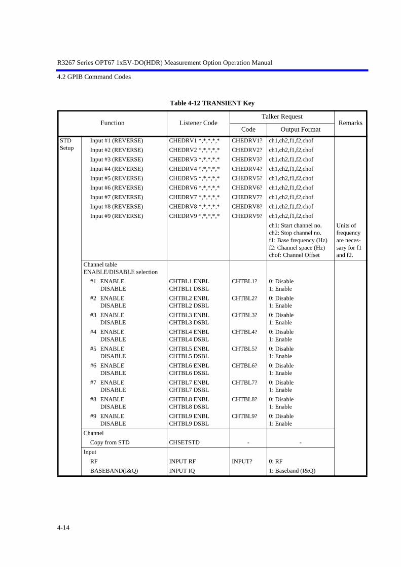
R3267 Series OPT67 1xEV-DO(HDR) Measurement Option Operation Manual
4.2 GPIB Command Codes
Table 4-12 TRANSIENT Key
Function Listener CodeTalker Request
RemarksCode Output Format
STD Setup
Input #1 (REVERSE) CHEDRV1 *,*,*,*,* CHEDRV1? ch1,ch2,f1,f2,chof
Input #2 (REVERSE) CHEDRV2 *,*,*,*,* CHEDRV2? ch1,ch2,f1,f2,chof
Input #3 (REVERSE) CHEDRV3 *,*,*,*,* CHEDRV3? ch1,ch2,f1,f2,chof
Input #4 (REVERSE) CHEDRV4 *,*,*,*,* CHEDRV4? ch1,ch2,f1,f2,chof
Input #5 (REVERSE) CHEDRV5 *,*,*,*,* CHEDRV5? ch1,ch2,f1,f2,chof
Input #6 (REVERSE) CHEDRV6 *,*,*,*,* CHEDRV6? ch1,ch2,f1,f2,chof
Input #7 (REVERSE) CHEDRV7 *,*,*,*,* CHEDRV7? ch1,ch2,f1,f2,chof
Input #8 (REVERSE) CHEDRV8 *,*,*,*,* CHEDRV8? ch1,ch2,f1,f2,chof
Input #9 (REVERSE) CHEDRV9 *,*,*,*,* CHEDRV9? ch1,ch2,f1,f2,chof
ch1: Start channel no.ch2: Stop channel no.f1: Base frequency (Hz)f2: Channel space (Hz)chof: Channel Offset
Units of frequency are neces-sary for f1 and f2.
Channel tableENABLE/DISABLE selection
#1 ENABLE DISABLE
CHTBL1 ENBLCHTBL1 DSBL
CHTBL1? 0: Disable1: Enable
#2 ENABLE DISABLE
CHTBL2 ENBLCHTBL2 DSBL
CHTBL2? 0: Disable1: Enable
#3 ENABLEDISABLE
CHTBL3 ENBLCHTBL3 DSBL
CHTBL3? 0: Disable1: Enable
#4 ENABLEDISABLE
CHTBL4 ENBLCHTBL4 DSBL
CHTBL4? 0: Disable1: Enable
#5 ENABLEDISABLE
CHTBL5 ENBLCHTBL5 DSBL
CHTBL5? 0: Disable1: Enable
#6 ENABLEDISABLE
CHTBL6 ENBLCHTBL6 DSBL
CHTBL6? 0: Disable1: Enable
#7 ENABLEDISABLE
CHTBL7 ENBLCHTBL7 DSBL
CHTBL7? 0: Disable1: Enable
#8 ENABLEDISABLE
CHTBL8 ENBLCHTBL8 DSBL
CHTBL8? 0: Disable1: Enable
#9 ENABLEDISABLE
CHTBL9 ENBLCHTBL9 DSBL
CHTBL9? 0: Disable1: Enable
Channel
Copy from STD CHSETSTD - -
Input
RF INPUT RF INPUT? 0: RF
BASEBAND(I&Q) INPUT IQ 1: Baseband (I&Q)
4-14

R3267 Series OPT67 1xEV-DO(HDR) Measurement Option Operation Manual
4.2 GPIB Command Codes
Table 4-12 TRANsIENT Key
Function Listener CodeTalker Request
RemarksCode Output Format
STD Setup
Baseband Input
AC BBINPUT AC BBINPUT? 0: AC
DC BBINPUT DC 1: DC
IQ Inverse
NORMAL IQMD NORM IQMD? 0:NORMAL
INVERSE IQMD INV 1:INVERSE
Auto Level setting
Auto Level OFF ALS OFF ALS? 0: OFF
Auto Level ON ALS ON 1: ON
DC CAL CLDC - -
4-15

R3267 Series OPT67 1xEV-DO(HDR) Measurement Option Operation Manual
4.2 GPIB Command Codes
Table 4-12 TRANSIENT Key
Function Listener CodeTalker Request
RemarksCode Output Format
T-Domain Power
Auto Level Set AUTOWFL - -
TDPAUTOLVL
Trigger Setup
Trigger Source
FREERUN TRGSRC FREE TRGSRC? 0:FREERUN
TDPTRGSRC FREE TDPTRGSRC? 1:VIDEO
VIDEO TRGSRC VIDEO 2:IF
TDPTRGSRC VIDEO 3:EXT
IF TRGSRC IF
TDPTRGSRC IF
EXT TRGSRC EXT
TDPTRGSRC EXT
Trigger Slope
+ TRGSLP RISE TRGSLP? 0:-
TDPTRGSLP RISE TDPTRGSLP? 1:+
- TRGSLP FALL
TDPTRGSLP FALL
Trigger Level TRGLVL * TRGLVL? Integer (0 to 100)
TDPTRGLVL * TDPTRGLVL?
Trigger Position TRGPOS * TRGPOS? Integer (0 to 100)
TDPTRGPOS * TDPTRGPOS?
Delay Time TRGDT * TRGDT? Time
TDPTRGDT * TDPTRGDT?
Window Setup
Window
ON TDPWDO ON TDPWDO? 0:OFF
TWDO ON TWDO? 1:ON
OFF TDPWDO OFF
TWDO OFF
Window Position TDPWPOS * TDPWPOS? Time
TWLX * TWLX?
Window Width TDPWWID * TDPWWID? Time
TWDX * TWDX?
Y Scale
10dB/div TDPDIV P10DB TDPDIV? 0:10dB/div
5dB/div TDPDIV P5DB 1: 5dB/div
2dB/div TDPDIV P2DB 2: 2dB/div
4-16

R3267 Series OPT67 1xEV-DO(HDR) Measurement Option Operation Manual
4.2 GPIB Command Codes
Table 4-12 TRANSIENT Key
Function Listener CodeTalker Request
RemarksCode Output Format
T-Domain Power
Average Times TDPAVGCNT * TDPAVGCNT? Integer (1:OFF, 2 to 999)
TDPAVG * TDPAVG? Integer (1:OFF, 2 to 999) *1
CAVGAT * CAVGAT? Integer (1:OFF, 2 to 999) *1
Average Mode
TRACE AVG TDPAVGMD TRACE TDPAVGMD? 0: Trace Avg
MAX HOLD TDPAVGMD MAX 1: Max Hold
POWER AVG TDPAVGMD POWER 2: Power Avg
NUMERIC TDPAVGMD NUMERIC 3: Numeric
Template
Template
ON TDPTMPL ON TDPTMPL? 0:OFF
TLMT ON TLMT? 1:ON
OFF TDPTMPL OFF
TLMT OFF
Template Shift
Shift X TDPTMPLSX * TDPTMPLSX? Time
TLMSFT * TLMSFT? Time
Shift Y TDPTMPLSY * TDPTMPLSY? Level
TLMASFT * TLMASFT? Level
Template Edit
Template UP/LOW select
TDPTMPLSEL UPTDPTMPLSEL LOW
TDPTMPLSEL? 0:UP1:LOW
Copy from STD TDPTMPLCP - -
LMCPSL STD
Data entry TDPTMPLED *,* - t1,l1
TLMIN *,* t1:Time
l1:Level (dBm/W/dBµV)
Init Table TDPTMPLCLR - -
TLMDEL
Parameter Setup
Detector
Normal TDPDET NRM TDPDET? 0:Normal
Posi TDPDET POS 1:Posi
Nega TDPDET NEG 2:Nega
Sample TDPDET SMP 3:Sample
*1: Average Mode is set to POWER AVG.
4-17

R3267 Series OPT67 1xEV-DO(HDR) Measurement Option Operation Manual
4.2 GPIB Command Codes
Table 4-12 TRANSIENT Key
Function Listener CodeTalker Request
RemarksCode Output Format
T-Domain Power
Display Unit
dBm TDPUNIT DBM TDPUNIT? 0:dBm
W TDPUNIT W 1:W
dBµV TDPUNIT DBUV 2:dBµV
Template Couple to Power
ON TDPTMPLPW ON TDPTMPLPW? 0:OFF
OFF TDPTMPLPW OFF 1:ON
Template Limit TDPTMPLBTM * TDPTMPLBTM? Level(dBm/W/dBµV)
Judgment
ON TDPJDG ON TDPJDG? 0:OFF
OFF TDPJDG OFF 1:ON
Upper Limit TDPJDGUP * TDPJDGUP? Level
Lower Limit TDPJDGLOW * TDPJDGLOW? Level
Set to STD TDPSETSTD - -
Starts measurement
T-Domain Power GATEPOW - -
TDPMEAS
Starts measurement in the same mode
SI - -
Measurement results
T-Domain Power - TDPMEAS? l1,j1
l1:Level(dBm/W/dBmV)
j1:Integer(0:FAIL,1:PASS,-1:Judgment OFF)
GATEPOW? l1:Level (dBm)
4-18

R3267 Series OPT67 1xEV-DO(HDR) Measurement Option Operation Manual
4.2 GPIB Command Codes
Table 4-12 TRANSIENT Key
Function Listener CodeTalker Request
RemarksCode Output Format
ON/OFF Ratio
Auto Level Set OORAUTOLVL - -
Trigger Setup
Trigger Source
FREERUN OORTRGSRC FREE OORTRGSRC? 0:FREERUN
VIDEO OORTRGSRC VIDEO 1:VIDEO
IF OORTRGSRC IF 2:IF
EXT OORTRGSRC EXT 3:EXT
Trigger Slope
+ OORTRGSLP RISE OORTRGSLP? 0:-
- OORTRGSLP FALL 1:+
Trigger Level OORTRGLVL * OORTRGLVL? Integer (0 to 100)
Trigger Position OORTRGPOS * OORTRGPOS? Integer (0 to 100)
Delay Time OORTRGDT * OORTRGDT? Time
Window Setup
Window
ON OORWDO ON OORWDO? 0:OFF
OFF OORWDO OFF 1:ON
ON Position OORWONPOS * OORWONPOS? Time
ON Width OORWONWID * OORWONWID? Time
OFF Position OORWOFPOS * OORWOFPOS? Time
OFF Width OORWOFWID * OORWOFWID? Time
Y Scale
10dB/div OORDIV P10DB OORDIV? 0:10dB/div
5dB/div OORDIV P5DB 1:5dB/div
2dB/div OORDIV P2DB 2:2dB/div
Average Times OORAVGCNT * OORAVGCNT? Integer (1:OFF,2 to 999)
OORAVG * OORAVG? Integer (1:OFF,2 to 999)
*1
CAVGRAT * CAVGRAT? Integer (1:OFF,2 to 999)
*1
Average Mode
TRACE AVG OORAVGMD TRACE OORAVGMD? 0: Trace Avg
MAX HOLD OORAVGMD MAX 1: Max Hold
POWER AVG OORAVGMD POWER 2: Power Avg
NUMERIC OORAVGMD NUMERIC 3: Numeric
*1: Average Mode is set to NUMERIC.
4-19

R3267 Series OPT67 1xEV-DO(HDR) Measurement Option Operation Manual
4.2 GPIB Command Codes
Table 4-12 TRANSIENT Key
Function Listener CodeTalker Request
RemarksCode Output Format
ON/OFF Ratio
Parameter Setup
Detector
Normal OORDET NRM OORDET? 0:Normal
Posi OORDET POS 1:Posi
Nega OORDET NEG 2:Nega
Sample OORDET SMP 3:Sample
Display Unit
dBm OORUNIT DBM OORUNIT? 0:dBm
W OORUNIT W 1:W
dBµV OORUNIT DBUV 2:dBµV
Judgment
ON OORJDG ON OORJDG? 0:OFF
OFF OORJDG OFF 1:ON
Upper Limit OORJDGUP * OORJDGUP? Level
Set to STD OORSETSTD - -
Starts measurement
ON/OFF Ratio OORMEAS - -
RATIO
Starts measurement in the same mode
SI - -
Measurement results
ON/OFF Ratio - OORMEAS? l1,l2,d1,j1
l1:ON Level(dBm/W/dBµV)
l2:OFF Level(dBm/W/dBµV)
d1:ON/OFF Ratio (dB)
j1:Integer(0:FAIL,1:PASS,-1:Judgment OFF)
RATIO? d1,l1
d1:ON/OFF Ratio (dB)
l1:Gated Power (dBm)
4-20

R3267 Series OPT67 1xEV-DO(HDR) Measurement Option Operation Manual
4.2 GPIB Command Codes
Table 4-12 TRANSIENT Key
Function Listener CodeTalker Request
RemarksCode Output Format
T-Domain Spurious
Auto Level Set TDSAUTOLVL - -
Trigger Setup
Trigger Source
FREERUN TDSTRGSRC FREE TDSTRGSRC? 0:FREERUN
TRSPMD FREE TRSPMD? 2:IF
IF TDSTRGSRC IF 3:EXT
TRSPMD IF
EXT TDSTRGSRC EXT
TRSPMD EXT
Trigger Slope
+ TDSTRGSLP RISE TDSTRGSLP? 0:-
TRSPSLP RISE 1:+
- TDSTRGSLP FALL TRSPSLP?
TRSPSLP FALL
Trigger Level TDSTRGLVL * TDSTRGLVL? Integer (0 to 100)
Trigger Position TDSTRGPOS * TDSTRGPOS? Integer (0 to 100)
Delay Time TDSTRGDT * TDSTRGDT? Time
Table
Table No. 1/2/3 TDSTBL * TDSTBL? Integer (1 to 3)
Table Edit TDSTBLED *,* - f1,l1
f1:Frequency
l1:Limit Level
Load Table TDSLD - -
Load Table 1/2/3 RCLTBL * - Integer (1 to 3)
Save Table TDSSV - -
Save Table 1/2/3 SVSTBL * - Integer (1 to 3)
Init Table TDSCLR - -
DELSTBL
Table Freq. InputABSREL
TDSTBLF ABSTDSTBLF REL
TDSTBLF? 0:ABS1:REL
Average Times TDSAVGCNT * TDSAVGCNT? Integer (1:OFF,2 to 999)
TDSAVG * TDSAVG? Integer (1:OFF,2 to 999)
*1
*1: When Detector is set to Positive, Average Mode is set to MAX HOLD. When Detector is set to something other than Positive, Average Mode is set to TRACE AVG.
4-21

R3267 Series OPT67 1xEV-DO(HDR) Measurement Option Operation Manual
4.2 GPIB Command Codes
Table 4-12 TRANSIENT Key
Function Listener CodeTalker Request
RemarksCode Output Format
T-Domain Spurious
Average Mode
TRACE AVG TDSAVGMD TRACE TDSAVGMD? 0: Trace Avg
MAX HOLD TDSAVGMD MAX 1: Max Hold
POWER AVG TDSAVGMD POWER 2: Power Avg
NUMERIC TDSAVGMD NUMERIC 3: Numeric
Parameter Setup
Detector
Normal TDSDET NRM TDSDET? 0:Normal
Posi TDSDET POS 1:Posi
Nega TDSDET NEG 2:Nega
Sample TDSDET SMP 3:Sample
Display Unit
dBm TDSUNIT DBM TDSUNIT? -
W TDSUNIT W
dBµV TDSUNIT DBUV
Judgment
ON TDSJDG ON TDSJDG? 0:OFF
OFF TDSJDG OFF 1:ON
Result
Peak TDSRES PK TDSRES? 0:Peak
RMS TDSRES RMS 1:RMS
Multiplier TDSMULTI * TDSMULTI? Real number
Peak Marker Y-Delta TDSPKMKY * TDSPKMKY? Real number
Preselector 1.6G TDSPRE 16G TDSPRE? 0:1.6G
3.6G TDSPRE 36G 1:3.6G
Set to Default TDSSETSTD - -
Starts measurement
Spurious TDSMEAS - -
SPUR
Starts measurement in the same mode
SI - -
Measurement results
Spurious - TDSMEAS? n<CR+LF>+f1,l1,j1<CR+LF>..... +fn,ln,jn<CR+LF>
n:Amount (Integer)
fn:Frequency
ln:Level(dBm/W/dBµV)
4-22

R3267 Series OPT67 1xEV-DO(HDR) Measurement Option Operation Manual
4.2 GPIB Command Codes
Table 4-12 TRANSIENT Key
Function Listener CodeTalker Request
RemarksCode Output Format
T-Domain Spurious
jn:Integer(0:FAIL,1:PASS,-1:Judgment OFF)
SPULVL? n<CR+LF>+f1,l1<CR+LF>..... +fn,ln<CR+LF>
n:Amount (Integer)
fn:Frequency
ln:Level (dBm)
F-Domain Power
Auto Level Set FDPAUTOLVL - -
Gate Setup
ONOFF
TGTSETUP ONTGTSETUP OFF
TGTSETUP? 0:OFF1:ON
Trigger Source
FREERUN TGTTRG FREE TGTTRG? 0:FREERUN
VIDEO TGTTRG VIDEO 1:VIDEO
IF TGTTRG IF 2:IF
EXT TGTTRG EXT 3:EXT
Trigger Slope
- TGTTRGSLP FALL TGTTRGSLP? 0:-
+ TGTTRGSLP RISE 1:+
Trigger Level TGTTRGLVL * TGTTRGLVL? Integer (0 to 100)
Trigger Position TGTTRGPOS * TGTTRGPOS? Integer (0 to 100)
Delay Time TGTTRGDT * TGTTRGDT? Time
Gate Source
Trigger TGTSRC TRG TGTSRC? 0:Trigger
Ext Gate TGTSRC EXT 1:EXT
Gate Position TGTPOS * TGTPOS? Time
Gate Width TGTWID * TGTWID? Time
Detector
Normal TGTDET NRM TGTDET? 0:Normal
Posi TGTDET POS 1:Posi
Nega TGTDET NEG 2:Nega
Sample TGTDET SMP 3:Sample
Gated Sweep ON/OFF
ON TGTSWP ON TGTSWP? 0:OFF
OFF TGTSWP OFF 1:ON
4-23

R3267 Series OPT67 1xEV-DO(HDR) Measurement Option Operation Manual
4.2 GPIB Command Codes
Table 4-12 TRANSIENT Key
Function Listener CodeTalker Request
RemarksCode Output Format
F-Domain Power
Window Setup
Window
ON FDPWDO ON FDPWDO? 0:OFF
OFF FDPWDO OFF 1:ON
Window Position FDPWPOS * FDPWPOS? Frequency
CPWLX * CPWLX?
Window Width FDPWWID * FDPWWID? Frequency
CPWDX * CPWDX?
Y Scale
10dB/div FDPDIV P10DB FDPDIV? 0:10dB/div
CPWDIV P10DB CPWDIV? 1:5dB/div
5dB/div FDPDIV P5DB 2:2dB/div
CPWDIV P5DB
2dB/div FDPDIV P2DB
CPWDIV P2DB
Average Times FDPAVGCNT * FDPAVGCNT? Integer (1:OFF, 2 to 999)
FDPAVG * FDPAVG? Integer (1:OFF, 2 to 999) *1
CAVGCHP * CAVGCHP? Integer (1:OFF, 2 to 999) *1
Average Mode
TRACE AVG FDPAVGMD TRACE FDPAVGMD? 0: Trace Avg
MAX HOLD FDPAVGMD MAX 1: Max Hold
POWER AVG FDPAVGMD POWER 2: Power Avg
NUMERIC FDPAVGMD NUMERIC 3: Numeric
Parameter Setup
Detector
Normal FDPDET NRM FDPDET? 0:Normal
Posi FDPDET POS 1:Posi
Nega FDPDET NEG 2:Nega
Sample FDPDET SMP 3:Sample
Display Unit
dBm FDPUNIT DBM FDPUNIT? 0:dBm
W FDPUNIT W 1:W
dBµV FDPUNIT DBUV 2:dBµV
Judgment
ON FDPJDG ON FDPJDG? 0:OFF
OFF FDPJDG OFF 1:ON
*1: Average Mode is set to POWER AVG.
4-24

R3267 Series OPT67 1xEV-DO(HDR) Measurement Option Operation Manual
4.2 GPIB Command Codes
Table 4-12 TRANSIENT Key
Function Listener CodeTalker Request
RemarksCode Output Format
F-Domain Power
Upper Limit FDPJDGUP * FDPJDGUP? Level(dBm/W/dBµV)
Lower Limit FDPJDGLOW * FDPJDGLOW? Level(dBm/W/dBµV)
Set to STD FDPSETSTD - -
Starts measurement
F-Domain Power FDPMEAS - -
CCHPOW
Starts measurement in the same mode
SI - -
Measurement results
F-Domain Power - FDPMEAS? l1,j1l1:Level(dBm/W/dBmV)j1:Integer(0:FAIL,1:PASS,-1:Judgment OFF)
CCHPOW? l1,l2l1:Level (dBm)l2:Level (dBm/Hz)
OBW Auto Level Set OBWAUTOLVL - -
OBW% OBWPER * OBWPER? Real number(0.5 to 99.5)
COBWPER * COBWPER?
Average Times OBWAVGCNT * OBWAVGCNT? Integer(1:OFF, 2 to 999)
OBWAVG * OBWAVG? Integer(1:OFF, 2 to 999)
*1
CAVGOBW * CAVGOBW? Integer(1:OFF, 2 to 999)
*1
Average Mode
TRACE AVG OBWAVGMD TRACE OBWAVGMD? 0: Trace Avg
MAX HOLD OBWAVGMD MAX 1: Max Hold
POWER AVG OBWAVGMD POWER 2: Power Avg
NUMERIC OBWAVGMD NUMERIC 3: Numeric
*1: When Detector is set to Positive, Average Mode is set to MAX HOLD. When Detector is set to something other than Positive, Average Mode is set to TRACE AVG.
4-25

R3267 Series OPT67 1xEV-DO(HDR) Measurement Option Operation Manual
4.2 GPIB Command Codes
Table 4-12 TRANSIENT Key
Function Listener CodeTalker Request
RemarksCode Output Format
OBW Parameter Setup
Detector
Normal OBWDET NRM OBWDET? 0:Normal
COBWDET NRM COBWDET? 1:Posi
Posi OBWDET POS 2:Nega
COBWDET POS 3:Sample
Nega OBWDET NEG
COBWDET NEG
Sample OBWDET SMP
COBWDET SMP
Judgment
ON OBWJDG ON OBWJDG? 0:OFF
OFF OBWJDG OFF 1:ON
Upper Limit OBWJDGUP * OBWJDGUP? Frequency
Lower Limit OBWJDGLOW * OBWJDGLOW? Frequency
Set to STD OBWSETSTD - -
Starts measurement
OBW OBWMEAS - -
COBW
Starts measurement in the same mode
SI - -
Measurement results
OBW - OBWMEAS? f1,f2,f3,j1f1:OBW Frequencyf2:Lower side
frequencyf3:Higher side
frequencyj1: Integer
(0: FAIL, 1: PASS,-1: Judgment OFF)
COBW? f1,f2,f3f1:OBW Frequencyf2:Lower side
frequencyf3:Higher side
frequency
4-26

R3267 Series OPT67 1xEV-DO(HDR) Measurement Option Operation Manual
4.2 GPIB Command Codes
Table 4-12 TRANSIENT Key
Function Listener CodeTalker Request
RemarksCode Output Format
Due to Transient
Auto Level Set DTSAUTOLVL - -
Template
Template
ON DTSTMPL ON DTSTMPL? 0: OFF
OFF DTSTMPL OFF 1: ON
Template Shift
Shift X DTSTMPLSX * DTSTMPLSX? Frequency
Shift Y DTSTMPLSY * DTSTMPLSY? Level
Margin delta X DTSTMPLDX * DTSTMPLDX? Frequency (0:OFF)
Copy from STD DTSTMPLCP - -
Data entry DTSTMPLED *,* - f1,l1f1: Frequencyl1: Level
(dBm/W/dBµV)
Init Table DTSTMPLCLR - -
Marker Edit
Copy from STD DTSMKRCP - -
Data entry DTSMKRED *,*,*,* - d1,f1,f2,l1d1: (0:Normal 1: Integral
2: √Nyquist)f1: Offset Frequencyf2: Band widthl1: Limit level
Set the reference bandwidth to f2, after initializing the table.
Init Table DTSMKRCLR - -
Average Times DTSAVGCNT * DTSAVGCNT? Integer (1:OFF, 2 to 999)
DTSAVG * DTSAVG? Integer (1:OFF, 2 to 999) *1
Average Mode
TRACE AVG DTSAVGMD TRACE DTSAVGMD? 0: Trace Avg
MAX HOLD DTSAVGMD MAX 1: Max Hold
POWER AVG DTSAVGMD POWER 2: Power Avg
NUMERIC DTSAVGMD NUMERIC 3: Numeric
*1: When Detector is set to Positive, Average Mode is set to MAX HOLD. When Detector is set to something other than Positive, Average Mode is set to TRACE AVG.
4-27

R3267 Series OPT67 1xEV-DO(HDR) Measurement Option Operation Manual
4.2 GPIB Command Codes
Table 4-12 TRANSIENT Key
Function Listener CodeTalker Request
RemarksCode Output Format
Due to Transient
Parameter Setup
Detector
Normal DTSDET NRM DTSDET? 0: Normal
Posi DTSDET POS 1: Posi
Nega DTSDET NEG 2: Nega
Sample DTSDET SMP 3: Sample
Display Unit
dBm DTSUNIT DBM DTSUNIT? 0: dBm
W DTSUNIT W 1: W
dBµV DTSUNIT DBUV 2: dBµV
Template Couple to Power
ON DTSTMPLPW ON DTSTMPLPW? 0: OFF
OFF DTSTMPLPW OFF 1: ON
Template Limit DTSTMPLBTM * DTSTMPLBTM? Level (dBm/W/dBµV)
Judgment
ONOFF
DTSJDG ONDTSJDG OFF
DTSJDG? 0: OFF1: ON
Freq. Setting
CFSPSTSP
DTSFRMD CFSPDTSFRMD STSP
DTSFRMD? 0: Center/Span mode1: Start/Stop mode
Result
ABSRELMKR
DTSRES ABSDTSRES RELDTSRES MKR
DTSRES? 0: Absolute1: Relative2: Marker
Ref Power
MKRMOD
DTSREF MKRDTSREF MOD
DTSREF? 0: Reference Marker1: Modulation
Symbol Rate 1/T DTSSYMRT * DTSSYMRT? Frequency
Rolloff Factor DTSRFACT * DTSRFACT? Real number
Set to STD DTSSETSTD - -
Starts measurement
Due to Transient DTSMEAS - -
Starts measurement in the same mode
SI - -
4-28

R3267 Series OPT67 1xEV-DO(HDR) Measurement Option Operation Manual
4.2 GPIB Command Codes
Table 4-12 TRANSIENT Key
Function Listener CodeTalker Request
RemarksCode Output Format
Due to Transient
Measurement results
Due to Transient - DTSMEAS? n<CR+LF>+d1,j1<CR+LF>..... +dn,jn<CR+LF>n:Amount (Integer)dn: Powerjn: Integer
(0: FAIL, 1: PASS, -1: Judgment OFF)
COBWCP? l1,l2,d1,d2,d3,d4l1: Level
(dBm: Reference power)
l2: Level (W: Reference power)d1: -1st ACP(dBc)d2: +1st ACP(dBc)d3: -2nd ACP(dBc)d4: +2nd ACP(dBc)
Ref. Power - DTSREFPWR? Level
Due to Modula-tion
Auto Level Set DTMAUTOLVL - -
Gate Setup
ONOFF
TGTSETUP ONTGTSETUP OFF
TGTSETUP? 0: OFF1: ON
Trigger Source
FREERUN TGTTRG FREE TGTTRG? 0: FREERUN
VIDEO TGTTRG VIDEO 1: VIDEO
IF TGTTRG IF 2: IF
EXT TGTTRG EXT 3: EXT
Trigger Slope
- TGTTRGSLP FALL TGTTRGSLP? 0: -
+ TGTTRGSLP RISE 1: +
Trigger Level TGTTRGLVL * TGTTRGLVL? Integer (0 to 100)
Trigger Position TGTTRGPOS * TGTTRGPOS? Integer (0 to 100)
Delay Time TGTTRGDT * TGTTRGDT? Time
Gate Source
Trigger TGTSRC TRG TGTSRC? 0: Trigger
Ext Gate TGTSRC EXT 1: EXT
Gate Position TGTPOS * TGTPOS? Time
Gate Width TGTWID * TGTWID? Time
4-29

R3267 Series OPT67 1xEV-DO(HDR) Measurement Option Operation Manual
4.2 GPIB Command Codes
Table 4-12 TRANSIENT Key
Function Listener CodeTalker Request
RemarksCode Output Format
Due to Modulation
Detector
Normal TGTDET NRM TGTDET? 0: Normal
Posi TGTDET POS 1: Posi
Nega TGTDET NEG 2: Nega
Sample TGTDET SMP 3: Sample
Gated Sweep ON/OFF
ON TGTSWP ON TGTSWP? 0: OFF
OFF TGTSWP OFF 1: ON
Template
Template
ON DTMTMPL ON DTMTMPL? 0: OFF
OFF DTMTMPL OFF 1: ON
Template Shift
Shift X DTMTMPLSX * DTMTMPLSX? Frequency
Shift Y DTMTMPLSY * DTMTMPLSY? Level
Margin delta X DTMTMPLDX * DTMTMPLDX? Frequency (0:OFF)
Copy from STD DTMTMPLCP - -
Data entry DTMTMPLED *,* - f1,l1f1: frequencyl1: Level(dBm/W/dBµV)
Init Table DTMTMPLCLR - -
Marker Edit
Copy from STD DTMMKRCP - -
Data entry DTMMKRED *,*,*,* - d1,f1,f2,l1d1: (0:Normal 1: Integral2: √Nyquist)f1: Offset Frequencyf2: Bandwidthl1: Limit Level
Set the refer-ence band-width to f2, after initial-izing the table.
Init Table DTMMKRCLR - -
Average Times DTMAVGCNT * DTMAVGCNT? Integer (1:OFF, 2 to 999)
DTMAVG * DTMAVG? Integer (1:OFF, 2 to 999)
*1
*1: When Detector is set to Positive, Average Mode is set to MAX HOLD. When Detector is set to something other than Positive, Average Mode is set to TRACE AVG.
4-30

R3267 Series OPT67 1xEV-DO(HDR) Measurement Option Operation Manual
4.2 GPIB Command Codes
Table 4-12 TRANSIENT Key
Function Listener CodeTalker Request
RemarksCode Output Format
Due to Modulation
Average Mode
TRACE AVG DTMAVGMD TRACE DTMAVGMD? 0: Trace Avg
MAX HOLD DTMAVGMD MAX 1: Max Hold
POWER AVG DTMAVGMD POWER 2: Power Avg
NUMERIC DTMAVGMD NUMERIC 3: Numeric
Parameter Setup
Detector
Normal DTMDET NRM DTMDET? 0: Normal
Posi DTMDET POS 1: Posi
Nega DTMDET NEG 2: Nega
Sample DTMDET SMP 3: Sample
Display Unit
dBm DTMUNIT DBM DTMUNIT? 0: dBm
W DTMUNIT W 1: W
dBµV DTMUNIT DBUV 2: dBµV
Template Couple to Power
ON DTMTMPLPW ON DTMTMPLPW? 0: OFF
OFF DTMTMPLPW OFF 1: ON
Template Limit DTMTMPLBTM * DTMTMPLBTM? Level (dBm/W/dBµV)
Judgment
ON DTMJDG ON DTMJDG? 0: OFF
OFF DTMJDG OFF 1: ON
Freq. Setting
CFSP DTMFRMD CFSP DTMFRMD? 0: Center/Span mode
STSP DTMFRMD STSP 1: Start/Stop mode
Result
ABS DTMRES ABS DTMRES? 0: Absolute
REL DTMRES REL 1: Relative
MKR DTMRES MKR 2: Marker
4-31

R3267 Series OPT67 1xEV-DO(HDR) Measurement Option Operation Manual
4.2 GPIB Command Codes
Table 4-12 TRANSIENT Key
Function Listener CodeTalker Request
RemarksCode Output Format
Due to Modula-tion
Ref Power
MKR DTMREF MKR DTMREF MKR? 0: Reference Marker
MOD DTMREF MOD 1: Modulation
Symbol Rate 1/T DTMSYMRT * DTMSYMRT? Frequency
Rolloff Factor DTMRFACT * DTMRFACT? Real number
Set to STD DTMSETSTD - -
Starts measurement
Due to Modulation DTMMEAS - -
Starts measurement in the same mode
SI - -
Measurement results
Due to Modulation - DTMMEAS? n<CR+LF>+d1, j1<CR+LF> .....+dn,jn<CR+LF>n: Amount (Integer)dn: Powerjn: Integer (0: FAIL, 1: PASS, -1: Judgment OFF)
Ref. Power - DTMREFPWR? Level
Inband Spurious (1)
Auto Level Set SPRAUTOLVL - -
Template
Template
ON SPRTMPL ON SPRTMPL? 0: OFF
OFF SPRTMPL OFF 1: ON
Template Shift
Shift X SPRTMPLSX * SPRTMPLSX? Frequency
Shift Y SPRTMPLSY * SPRTMPLSY? Level
Margin delta X SPRTMPLDX * SPRTMPLDX? Frequency (0:OFF)
Copy from STD SPRTMPLCP - -
Data entry SPRTMPLED *,* - f1,l1f1: Frequencyl1: Level (dBm/W/dBµV)
Init Table SPRTMPLCLR - -
Marker Edit
Copy from STD SPRMKRCP - -
Data entry SPRMKRED *,*,*,* - d1,f1,f2,l1d1:(0:Peak, 1:Integral)f1: Start Frequencyf2: Stop Frequencyl1: Limit Level
Set the refer-ence band-width to f2, after initializ-ing the table.
Init Table SPRMKRCLR - -
4-32

R3267 Series OPT67 1xEV-DO(HDR) Measurement Option Operation Manual
4.2 GPIB Command Codes
Table 4-12 TRANSIENT Key
Function Listener CodeTalker Request
RemarksCode Output Format
Inband Spurious (1)
Average Times SPRAVGCNT * SPRAVGCNT? Integer(1:OFF, 2 to 999)
SPRAVG * SPRAVG? Integer(1:OFF, 2 to 999)
*1
CAVGSPR * CAVGSPR? Integer(1:OFF, 2 to 999)
*1
Average Mode
TRACE AVG SPRAVGMD TRACE SPRAVGMD? 0: Trace Avg
MAX HOLD SPRAVGMD MAX 1: Max Hold
POWER AVG SPRAVGMD POWER 2: Power Avg
Parameter Setup
Detector
Normal SPRDET NRM SPRDET? 0: Normal
Posi SPRDET POS 1: Posi
Nega SPRDET NEG 2: Nega
Sample SPRDET SMP 3: Sample
Display Unit
dBm SPRUNIT DBM SPRUNIT? 0: dBm
W SPRUNIT W 1: W
dBµV SPRUNIT DBUV 2: dBµV
Template Couple to Power
ONOFF
SPRTMPLPW ONSPRTMPLPW OFF
SPRTMPLPW? 0: OFF1: ON
Template Limit SPRTMPLBTM * SPRTMPLBTM? Level(dBm/W/dBµV)
Judgment
ONOFF
SPRJDG ONSPRJDG OFF
SPRJDG? 0: OFF1: ON
Freq. Setting
CFSPSTSP
SPRFRMD CFSPSPRFRMD STSP
SPRFRMD? 0: Center/Span mode1: Start/Stop mode
*1: When Detector is set to Positive, Average Mode is set to MAX HOLD. When Detector is set to something other than Positive, Average Mode is set to TRACE AVG.
4-33
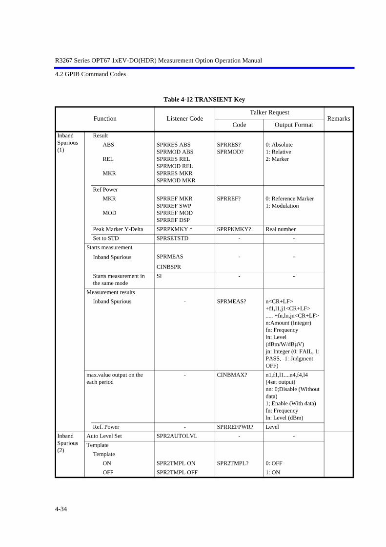
R3267 Series OPT67 1xEV-DO(HDR) Measurement Option Operation Manual
4.2 GPIB Command Codes
Table 4-12 TRANSIENT Key
Function Listener CodeTalker Request
RemarksCode Output Format
Inband Spurious (1)
Result
ABS
REL
MKR
SPRRES ABSSPRMOD ABSSPRRES RELSPRMOD RELSPRRES MKRSPRMOD MKR
SPRRES?SPRMOD?
0: Absolute1: Relative2: Marker
Ref Power
MKR
MOD
SPRREF MKRSPRREF SWPSPRREF MODSPRREF DSP
SPRREF? 0: Reference Marker1: Modulation
Peak Marker Y-Delta SPRPKMKY * SPRPKMKY? Real number
Set to STD SPRSETSTD - -
Starts measurement
Inband Spurious SPRMEAS - -
CINBSPR
Starts measurement in the same mode
SI - -
Measurement results
Inband Spurious - SPRMEAS? n<CR+LF>+f1,l1,j1<CR+LF>..... +fn,ln,jn<CR+LF>n:Amount (Integer)fn: Frequencyln: Level (dBm/W/dBµV)jn: Integer (0: FAIL, 1: PASS, -1: Judgment OFF)
max.value output on the each period
- CINBMAX? n1,f1,l1....n4,f4,l4(4set output)nn: 0;Disable (Without data)1; Enable (With data)fn: Frequencyln: Level (dBm)
Ref. Power - SPRREFPWR? Level
Inband Spurious (2)
Auto Level Set SPR2AUTOLVL - -
Template
Template
ON SPR2TMPL ON SPR2TMPL? 0: OFF
OFF SPR2TMPL OFF 1: ON
4-34

R3267 Series OPT67 1xEV-DO(HDR) Measurement Option Operation Manual
4.2 GPIB Command Codes
Table 4-12 TRANSIENT Key
Function Listener CodeTalker Request
RemarksCode Output Format
Inband Spurious (2)
Template Shift
Shift X SPR2TMPLSX * SPR2TMPLSX? Frequency
Shift Y SPR2TMPLSY * SPR2TMPLSY? Level
Margin delta X SPR2TMPLDX * SPR2TMPLDX? Frequency (0:OFF)
Copy from STD SPR2TMPLCP - -
Data entry SPR2TMPLED *,* - f1,l1f1: Frequencyl1: Level
(dBm/W/dBµV)
Init Table SPR2TMPLCLR - -
Marker Edit
Copy from STD SPR2MKRCP - -
Data entry SPR2MKRED *,*,*,* - d1,f1,f2,l1d1:(0:Peak, 1:Integral)f1: Start Frequencyf2: Stop Frequencyl1: Limit Level
Set the reference bandwidth to f2, after initializing the table.
Init Table SPR2MKRCLR - -
Average Times SPR2AVGCNT * SPR2AVGCNT? Integer(1:OFF, 2 to 999)
SPR2AVG * SPR2AVG? Integer(1:OFF, 2 to 999)
Average Mode
POWER AVG SPR2AVGMD POWER SPR2AVGMD? 2: Power Avg
Parameter Setup
Detector
Normal SPR2DET NRM SPR2DET? 0: Normal
Posi SPR2DET POS 1: Posi
Nega SPR2DET NEG 2: Nega
Sample SPR2DET SMP 3: Sample
Display Unit
dBm SPR2UNIT DBM SPR2UNIT? 0: dBm
W SPR2UNIT W 1: W
dBµV SPR2UNIT DBUV 2: dBµV
4-35

R3267 Series OPT67 1xEV-DO(HDR) Measurement Option Operation Manual
4.2 GPIB Command Codes
Table 4-12 TRANSIENT Key
Function Listener CodeTalker Request
RemarksCode Output Format
Inband Spurious (2)
Template Couple to Power
ON SPR2TMPLPW ON SPR2TMPLPW? 0: OFF
OFF SPR2TMPLPW OFF 1: ON
Template Limit SPR2TMPLBTM * SPR2TMPLBTM? Level (dBm/W/dBµV)
Judgment
ON SPR2JDG ON SPR2JDG? 0: OFF
OFF SPR2JDG OFF 1: ON
Freq. Setting
CFSP SPR2FRMD CFSP SPR2FRMD? 0: Center/Span mode
STSP SPR2FRMD STSP 1: Start/Stop mode
Result
ABS SPR2RES ABS SPR2RES? 0: Absolute
REL SPR2RES REL 1: Relative
MKR SPR2RES MKR 2: Marker
Ref Power
MKR SPR2REF MKR SPR2REF? 0: Reference Marker
MOD SPR2REF MOD 1: Modulation
Peak MKR Y-Delta SPR2PKMKY * SPR2PKMKY? Real number
Band Conversion
ON SPR2CONV ON SPR2CONV? 0: OFF
OFF SPR2CONV OFF 1: ON
Integral Band SPR2INTE * SPR2INTE? Frequency
Start Offset SPR2OFSST * SPR2OFSST? Frequency
Stop Offset SPR2OFSSP * SPR2OFSSP? Frequency
Set to STD SPR2SETSTD - -
Starts measurement
Inband Spurious SPR2MEAS - -
Starts measurement in the same mode
SI - -
Measurement results
Inband Spurious - SPR2MEAS? n<CR+LF>+f1,l1,j1<CR+LF>..... +fn,ln,jn<CR+LF>n:Amount (Integer)fn: Frequencyln: Level (dBm/W/dBµV)jn: Integer (0: FAIL, 1: PASS, -1: Judgment OFF)
Ref. Power - SPR2REFPWR? Level
4-36

R3267 Series OPT67 1xEV-DO(HDR) Measurement Option Operation Manual
4.2 GPIB Command Codes
Table 4-12 TRANSIENT Key
Function Listener CodeTalker Request
RemarksCode Output Format
Outband Spurious
Auto Level Set FDSAUTOLVL - -
Table
Copy from STD FDSCP
Table No.1/2/3 FDSTBL * FDSTBL? Integer (1 to 3)
Table Edit FDSTBLED *,*,*,*,*,* - f1,f2,f3,f4,d1,l1f1: Start frequencyf2: Stop frequencyf3: RBWf4: VBWd1: Sweep timel1: Limit Level
Load Table FDSLD - -
Save Table FDSSV - -
Init Table FDSCLR - -
Average Times FDSAVGCNT * FDSAVGCNT? Integer (1:OFF, 2 to 999)
FDSAVG * FDSAVG? Integer (1:OFF, 2 to 999)
*1
Average Mode
TRACE AVG FDSAVGMD TRACE FDSAVGMD? 0: Trace Avg
MAX HOLD FDSAVGMD MAX 1: Max Hold
POWER AVG FDSAVGMD POWER 2: Power Avg
Parameter Setup
Detector
Normal FDSDET NRM FDSDET? 0: Normal
Posi FDSDET POS 1: Posi
Nega FDSDET NEG 2: Nega
Sample FDSDET SMP 3: Sample
Display Unit
dBm FDSUNIT DBM FDSUNIT? 0: dBm
W FDSUNIT W 1: W
dBµV FDSUNIT DBUV 2: dBµV
Judgment
ON FDSJDG ON FDSJDG? 0: OFF
OFF FDSJDG OFF 1: ON
Peak Marker Y-Delta FDSPKMKY * FDSPKMKY? Real number
Preselector 1.6G FDSPRE 16G FDSPRE? 0: 1.6G
3.6G FDSPRE 36G 1: 3.6G
Set to Default FDSSETSTD - -
*1: When Detector is set to Positive, Average Mode is set to MAX HOLD. When Detector is set to something other than Positive, Average Mode is set to TRACE AVG.
4-37
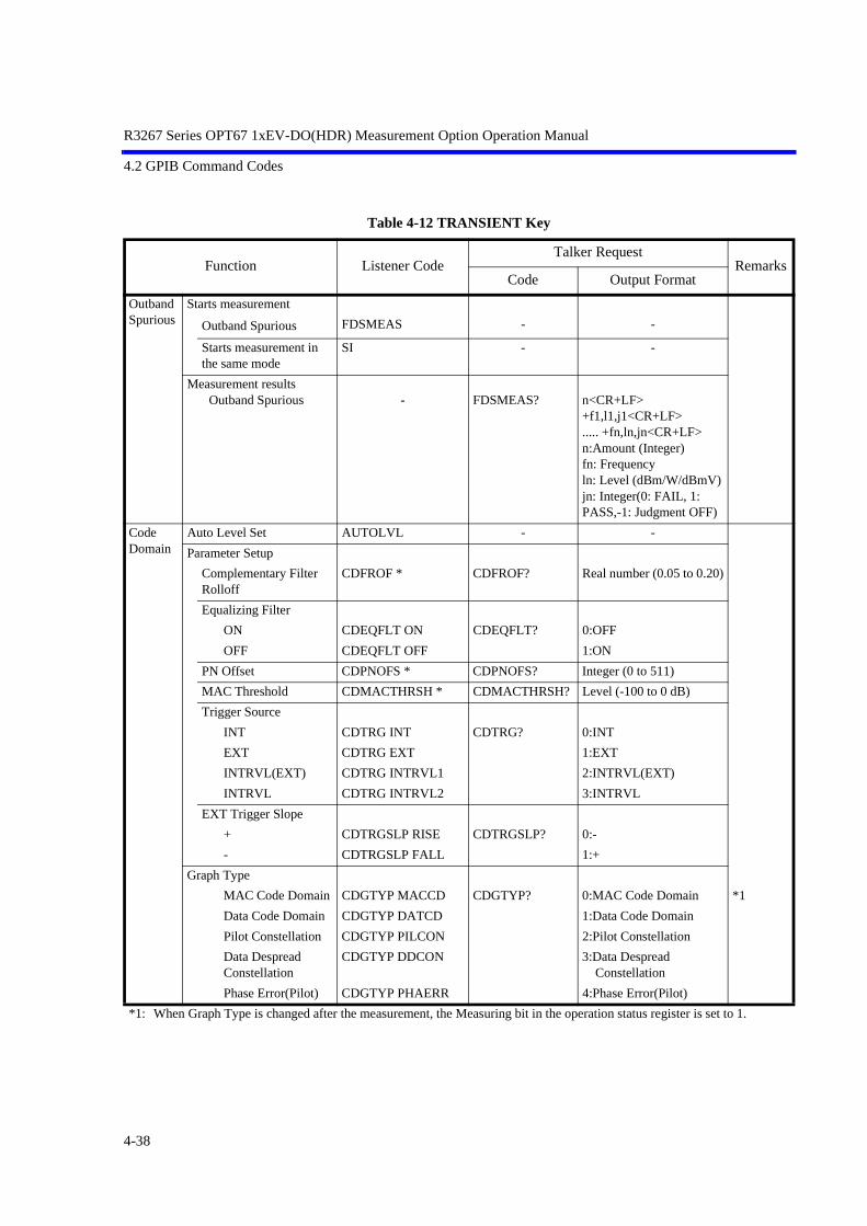
R3267 Series OPT67 1xEV-DO(HDR) Measurement Option Operation Manual
4.2 GPIB Command Codes
Table 4-12 TRANSIENT Key
Function Listener CodeTalker Request
RemarksCode Output Format
Outband Spurious
Starts measurement
Outband Spurious FDSMEAS - -
Starts measurement in the same mode
SI - -
Measurement resultsOutband Spurious - FDSMEAS? n<CR+LF>
+f1,l1,j1<CR+LF>..... +fn,ln,jn<CR+LF>n:Amount (Integer)fn: Frequencyln: Level (dBm/W/dBmV)jn: Integer(0: FAIL, 1: PASS,-1: Judgment OFF)
Code Domain
Auto Level Set AUTOLVL - -
Parameter Setup
Complementary Filter Rolloff
CDFROF * CDFROF? Real number (0.05 to 0.20)
Equalizing Filter
ON CDEQFLT ON CDEQFLT? 0:OFF
OFF CDEQFLT OFF 1:ON
PN Offset CDPNOFS * CDPNOFS? Integer (0 to 511)
MAC Threshold CDMACTHRSH * CDMACTHRSH? Level (-100 to 0 dB)
Trigger Source
INT CDTRG INT CDTRG? 0:INT
EXT CDTRG EXT 1:EXT
INTRVL(EXT) CDTRG INTRVL1 2:INTRVL(EXT)
INTRVL CDTRG INTRVL2 3:INTRVL
EXT Trigger Slope
+ CDTRGSLP RISE CDTRGSLP? 0:-
- CDTRGSLP FALL 1:+
Graph Type
MAC Code Domain CDGTYP MACCD CDGTYP? 0:MAC Code Domain *1
Data Code Domain CDGTYP DATCD 1:Data Code Domain
Pilot Constellation CDGTYP PILCON 2:Pilot Constellation
Data Despread Constellation
CDGTYP DDCON 3:Data Despread Constellation
Phase Error(Pilot) CDGTYP PHAERR 4:Phase Error(Pilot)
*1: When Graph Type is changed after the measurement, the Measuring bit in the operation status register is set to 1.
4-38

R3267 Series OPT67 1xEV-DO(HDR) Measurement Option Operation Manual
4.2 GPIB Command Codes
Table 4-12 TRANSIENT Key
Function Listener CodeTalker Request
RemarksCode Output Format
Code Domain
Starts measurement
Code Domain CDMEAS
Starts measurement in the same mode
SI
Measurement results
Carrier Frequency Error CDCFERR? d1,d2
d1:Frequency(Hz)
d2:Real number(ppm)
Pilot Time Alignment Error CDPTAERR? Time(sec)
ρ pilot CDRHOP? Real number
ρ overall-1 CDRHO1? Real number
ρ overall-2 CDRHO2? Real number
Peak MAC Inactive Channel CDPKINACT? Level(dB)
CDPKINACTL? d1,d2
d1:Real number(ρ)
d2:Level(dB)
Max Data Code Domain CDMAXCDP? d1,d2
d1:Real number(ρ)
d2:Level(dB)
Min Data Code Domain CDMINCDP? d1,d2
d1:Real number(ρ)
d2:Level(dB)
Modulation Type CDMODTYP? 0:idle
1:QPSK
2:8-PSK
3:16-QAM
PN Offset CDPNOFSR? Integer (0 to 511)
Preamble Chips(ρ overall-1) CDPRCHIP? Integer (chips)
Marker Position CDMK * CDMK? Integer
Walsh Code Number CDMKWNUM? Integer
ρMAC,real CDMKRHOMRE? Real number
ρMAC,imag CDMKRHOMIM? Real number
ρData,real CDMKRHODRE? Real number
ρData,imag CDMKRHODIM? Real number
MACIndex CDMKMACIDX? Integer
4-39

R3267 Series OPT67 1xEV-DO(HDR) Measurement Option Operation Manual
4.2 GPIB Command Codes
Table 4-12 TRANSIENT Key
Function Listener CodeTalker Request
RemarksCode Output Format
Code Domain
Marker Position
Chip number CDMKCHIP? d1,d2
Pilot Constellation
d1:Chip number
d2:Sample number
Phase Error (Pilot)
d1:Half Slot number
d2:Chip number
Symbol number CDMKSYM? d1,d2
d1:Symbol number
d2:Walsh Code No.
I-Phase data CDMKI? Phase
Q-Phase data CDMKQ? Phase
Phase error CDMKPHAERR? Real number(degree)
Read All Marker Data
Walsh Code Number CDMKGPHWNUM? n<CR+LF>+d1<CR+LF>+...+dn<CR+LF>
n:Number of output data (Integer)
dn:Walsh Code Number(Integer)
ρMAC,real CDMKGPHRHOMRE? n<CR+LF>+d1<CR+LF>+...+dn<CR+LF>
n:Number of output data (Integer)
dn:ρMAC,real (Real number)
ρMAC,imag CDMKGPHRHOMIM? n<CR+LF>+d1<CR+LF>+...+dn<CR+LF>
n:Number of output data (Integer)
dn:ρMAC,imag (Real number)
ρData,real CDMKGPHRHODRE? n<CR+LF>+d1<CR+LF>+...+dn<CR+LF>
n:Number of output data (Integer)
dn:ρData,real (Real number)
4-40

R3267 Series OPT67 1xEV-DO(HDR) Measurement Option Operation Manual
4.2 GPIB Command Codes
Table 4-12 TRANSIENT Key
Function Listener CodeTalker Request
RemarksCode Output Format
Code Domain
ρData,imag CDMKGPHRHODIM? n<CR+LF>+d1<CR+LF>+...+dn<CR+LF>
n:Number of output data (Integer)
dn:ρData,imag (Real number)
MACIndex CDMKGPHMACIDX? n<CR+LF>+d1<CR+LF>+...+dn<CR+LF>
n:Number of output data (Integer)
dn:MACIndex(Integer)
Chip number CDMKGPHCHIP? n<CR+LF>+d1<CR+LF>+...+dn<CR+LF>
n:Number of output data (Integer)
dn:Chip number (Integer)
Symbol number CDMKGPHSYM? n<CR+LF>+d1<CR+LF>+...+dn<CR+LF>
n:Number of output data (Integer)
dn:Symbol number (Integer)
I-Phase data CDMKGPHI? n<CR+LF>+d1<CR+LF>+...+dn<CR+LF>
n:Number of output data (Integer)
dn:Phase (Real number)
Q-Phase data CDMKGPHQ? n<CR+LF>+d1<CR+LF>+...+dn<CR+LF>
n:Number of output data (Integer)
dn:Phase (Real number)
Phase Error(Pilot) CDMKGPHPHAERR? n<CR+LF>+d1<CR+LF>+...+dn<CR+LF>
n:Number of output data (Integer)
dn:Phase Error(degree)
4-41
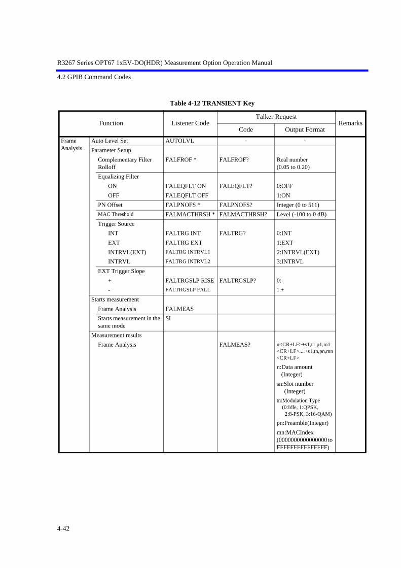
R3267 Series OPT67 1xEV-DO(HDR) Measurement Option Operation Manual
4.2 GPIB Command Codes
Table 4-12 TRANSIENT Key
Function Listener CodeTalker Request
RemarksCode Output Format
Frame Analysis
Auto Level Set AUTOLVL - -
Parameter Setup
Complementary Filter Rolloff
FALFROF * FALFROF? Real number(0.05 to 0.20)
Equalizing Filter
ON FALEQFLT ON FALEQFLT? 0:OFF
OFF FALEQFLT OFF 1:ON
PN Offset FALPNOFS * FALPNOFS? Integer (0 to 511)
MAC Threshold FALMACTHRSH * FALMACTHRSH? Level (-100 to 0 dB)
Trigger Source
INT FALTRG INT FALTRG? 0:INT
EXT FALTRG EXT 1:EXT
INTRVL(EXT) FALTRG INTRVL1 2:INTRVL(EXT)
INTRVL FALTRG INTRVL2 3:INTRVL
EXT Trigger Slope
+ FALTRGSLP RISE FALTRGSLP? 0:-
- FALTRGSLP FALL 1:+
Starts measurement
Frame Analysis FALMEAS
Starts measurement in the same mode
SI
Measurement results
Frame Analysis FALMEAS? n<CR+LF>+s1,t1,p1,m1<CR+LF>....+s1,tn,pn,mn<CR+LF>
n:Data amount (Integer)
sn:Slot number (Integer)
tn:Modulation Type (0:Idle, 1:QPSK, 2:8-PSK, 3:16-QAM)
pn:Preamble(Integer)
mn:MACIndex(0000000000000000 to FFFFFFFFFFFFFFF)
4-42

R3267 Series OPT67 1xEV-DO(HDR) Measurement Option Operation Manual
4.2 GPIB Command Codes
Table 4-12 TRANSIENT Key
Function Listener CodeTalker Request
RemarksCode Output Format
Frame Analysis
Measurement results
Carrier Frequency Error FALCFERR? Frequency(Hz)
Pilot Time Alignment Error
FALPTAERR? Time(sec)
PN Offset FALPNOFSR? Integer (0 to 511)
ρPilot FALRHOP? Real number (0.0 to 1.0)
Tx Power Auto Level Set AUTOLVL - -
Parameter Setup
Trigger Source
INT TXTRG INT TXTRG? 0:INT
EXT TXTRG EXT 1:EXT
INTRVL(EXT) TXTRG INTRVL1 2:INTRVL(EXT)
IF TXTRG IF 3:IF
EXT Trigger Slope
+ TXTRGSLP RISE TXTRGSLP? 0:-
- TXTRGSLP FALL 1:+
Trigger Level TXTRLVL * TXTRLVL? Integer (0 to 100)
EXT Trigger Delay TXTRGDLY * TXTRGDLY? Time
Average Times TXAVG * TXAVG? Integer (1:OFF, 2 to 32)
Starts measurement
Tx Power TXPWR - -
Starts measurement in the same mode
SI - -
Measurement results
Tx Power - TXPWR? d1,d2,d3d1: Tx Power(dBm/dB)d2: Tx Power(W)d3: Peak Factor(dB)
4-43

R3267 Series OPT67 1xEV-DO(HDR) Measurement Option Operation Manual
4.2 GPIB Command Codes
Table 4-12 TRANSIENT Key
Function Listener CodeTalker Request
RemarksCode Output Format
CCDF Auto Level Set AUTOLVL - -
Scale Setup
X Scale Max C2CCDFXMAX * C2CCDFXMAX? Integer (-20 to 70 dB/dBm)
X Scale Range C2CCDFXRNG * C2CCDFXRNG? Integer (10 to 50 dB/dBm)
Power Unit
RELATIVE C2CCDFUNIT REL C2CCDFUNIT? 0:ABS POWER
ABS POWER C2CCDFUNIT ABS 1:RELATIVE
Parameter Setup
Trigger Mode
INT C2CCDFTRG INT C2CCDFTRG? 0:INT
EXT C2CCDFTRG EXT 1:EXT
Trigger Slope
+ C2CCDFTRGSLP RISE C2CCDFTRGSLP? 0:-
- C2CCDFTRGSLP FALL 1:+
Trigger Delay C2CCDFTRGDLY * C2CCDFTRGDLY? Time
Meas Length C2CCDFMLEN * C2CCDFMLEN? Integer (10000 to 100000000)
Trace Write
ON C2CCDFTRC ON C2CCDFTRC? 0:OFF
OFF C2CCDFTRC OFF 1:ON
Starts measurement
CCDF C2CCDF - -
Starts measurement in the same mode
SI - -
Measurement results
CCDF - C2CCDF? d1,d2,d3,d4,d5,d6,d7,d8d1:Peak Factord2:Average Powerd3:10%d4:1%d5:0.1%d6:0.01%d7:0.001%d8:0.0001%
Marker Position C2CCDFMK * - Level
Distribution/Power - C2CCDFMK? d1,d2d1:Distributiond2:Power
4-44

R3267 Series OPT67 1xEV-DO(HDR) Measurement Option Operation Manual
4.2 GPIB Command Codes
Table 4-12 TRANSIENT Key
Function Listener CodeTalker Request
RemarksCode Output Format
Pilot/MAC Channel Power
Auto Level Set AUTOLVL - -
Parameter Setup
PN Offset PCPPNOFS * PCPPNOFS? Integer (0 to 511)
Bandpass Filter
ON PCPBNDFLT ON PCPBNDFLT? 0:OFF
OFF PCPBNDFLT OFF 1:ON
Trigger Source
INT PCPTRG INT PCPTRG? 0:INT
EXT PCPTRG EXT 1:EXT
INTRVL(EXT) PCPTRG INTRVL1 2:INTRVL(EXT)
INTRVL PCPTRG INTRVL2 3:INTRVL
EXT Trigger Slope
+ PCPTRGSLP RISE PCPTRGSLP? 0:-
- PCPTRGSLP FALL 1:+
Y Scale
10dB/div PCPDIV P10DB PCPDIV? 0:10dB/div
5dB/div PCPDIV P5DB 1:5dB/div
Template
Selecting Template
User Template PCPTEMP USER PCPTEMP? 0: User Template
STD Template PCPTEMP STD 1: STD Template
Editing Template PCPTENT d1,d2,d3 PCPTENT? d1,d2,d3
d1:Template level Y0(dB)
d2:Template level Y1(dB)
d3:Template level Y2(dB)
Average Times PCPAVG * PCPAVG? Integer (1:OFF, 2 to 512)
Starts measurement
Pilot/MAC Channel Power PCPMEAS
Starts measurement in the same mode
SI
Measurement results
Average PCPAVGR? Integer (1 to 512)
PN Offset PCPPNOFSR? Integer (0 to 511)
Burst Length PCPBRSTLEN? Time(sec)
ON Avg. PCPONAVGPW? Level(dBm)
ON Max. PCPONMAXPW? Level(dB)
ON Min. PCPONMINPW? Level(dB)
4-45

R3267 Series OPT67 1xEV-DO(HDR) Measurement Option Operation Manual
4.2 GPIB Command Codes
Table 4-12 TRANSIENT Key
Function Listener CodeTalker Request
RemarksCode Output Format
Pilot/MAC Channel Power
Measurement results
OFF Avg. PCPOFFAVGPW? Level(dB)
OFF Max. PCPOFFMAXPW? Level(dB)
Rise Up TIme PCPRISEUP? Time(sec)
Fall Down Time PCPFALLDN? Time(sec)
PASS/FAIL judgment PCPJDG? 0: FAIL
1: PASS
Marker Position PCPMK * PCPMK? Integer (0 to 4096)
PCPMKCHIP? d1,d2
d1:Chip number
d2:Sample number
Power PCPMKPW? Level(dB)
Read All Marker Data
X-axis data PCPMKGPHX? n<CR+LF>+d1<CR+LF>+...+dn<CR+LF>
n:Number of output data (Integer)
dn:Data(Integer)
Y-axis data PCPMKGPHY? n<CR+LF>+d1<CR+LF>+...+dn<CR+LF>
n:Number of output data (Integer)
dn:Data(Level)
Total Power
Auto Level Set AUTOLVL - -
Parameter Setup
PN Offset TPWPNOFS * TPWPNOFS? Integer (0 to 511)
Bandpass Filter
ON TPWBNDFLT ON TPWBNDFLT? 0:OFF
OFF TPWBNDFLT OFF 1:ON
Trigger Source
INT TPWTRG INT TPWTRG? 0:INT
EXT TPWTRG EXT 1:EXT
INTRVL(EXT) TPWTRG INTRVL1 2:INTRVL(EXT)
INTRVL TPWTRG INTRVL2 3:INTRVL
EXT Trigger Slope
+ TPWTRGSLP RISE TPWTRGSLP? 0:-
- TPWTRGSLP FALL 1:+
4-46

R3267 Series OPT67 1xEV-DO(HDR) Measurement Option Operation Manual
4.2 GPIB Command Codes
Table 4-12 TRANSIENT Key
Function Listener CodeTalker Request
RemarksCode Output Format
Total Power
Template
Selecting Template
User Template TPWTEMP USER TPWTEMP? 0: User Template
STD Template TPWTEMP STD 1: STD Template
Editing Template TPWTENT d1,d2 TPWTENT? d1,d2
d1:Template level Y0(dB)
d2:Template level Y1(dB)
Average Times TPWAVG * TPWAVG? Integer (1:OFF, 2 to 512)
Starts measurement
Total Power TPWMEAS
Starts measurement in the same mode
SI
Measurement results
Average TPWAVGR? Integer (1 to 512)
PN Offset TPWPNOFSR? Integer (0 to 511)
Average Power TPWAVGPW? Level(dBm)
Maximum Power TPWMAXPW? Level(dB)
Minimum Power TPWMINPW? Level(dB)
PASS/FAIL judgment TPWJDG? 0: FAIL
1: PASS
Marker Position TPWMK * TPWMK? Integer (0 to 4096)
TPWMKCHIP? d1,d2
d1:Chip number
d2:Sample number
Power TPWMKPW? Level(dB)
Read All Marker Data
X-axis data TPWMKGPHX? n<CR+LF>+d1<CR+LF>+...+dn<CR+LF>
n:Number of output data (Integer)
dn:Data(Integer)
Y-axis data TPWMKGPHY? n<CR+LF>+d1<CR+LF>+...+dn<CR+LF>
n:Number of output data (Integer)
dn:Data(Real number)
4-47

R3267 Series OPT67 1xEV-DO(HDR) Measurement Option Operation Manual
4.2 GPIB Command Codes
Table 4-13 Numeric Keys/Step Keys/Data Knob/Unit Keys (Entering Data)
Function Listener CodeTalker Request
RemarksCode Output Format
Entering data
0 to 9 0 to 9 - -
. (Decimal point) . - -
GHz GZ - -
MHz MZ - -
kHz KZ - -
Hz HZ - -
mV MV - -
mW MW - -
dB DB - -
mA MA - -
sec SC - -
ms MS - -
µs US - -
ENTER ENT - -
4-48
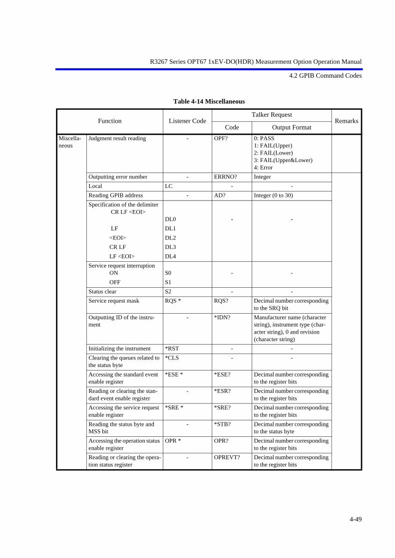
R3267 Series OPT67 1xEV-DO(HDR) Measurement Option Operation Manual
4.2 GPIB Command Codes
Table 4-14 Miscellaneous
Function Listener CodeTalker Request
RemarksCode Output Format
Miscella-neous
Judgment result reading - OPF? 0: PASS1: FAIL(Upper)2: FAIL(Lower)3: FAIL(Upper&Lower)4: Error
Outputting error number - ERRNO? Integer
Local LC - -
Reading GPIB address - AD? Integer (0 to 30)
Specification of the delimiter CR LF <EOI>
DL0 - -
LF DL1
<EOI> DL2
CR LF DL3
LF <EOI> DL4
Service request interruption ON S0 - -
OFF S1
Status clear S2 - -
Service request mask RQS * RQS? Decimal number corresponding to the SRQ bit
Outputting ID of the instru-ment
- *IDN? Manufacturer name (character string), instrument type (char-acter string), 0 and revision (character string)
Initializing the instrument *RST - -
Clearing the queues related to the status byte
*CLS - -
Accessing the standard event enable register
*ESE * *ESE? Decimal number corresponding to the register bits
Reading or clearing the stan-dard event enable register
- *ESR? Decimal number corresponding to the register bits
Accessing the service request enable register
*SRE * *SRE? Decimal number corresponding to the register bits
Reading the status byte and MSS bit
- *STB? Decimal number corresponding to the status byte
Accessing the operation status enable register
OPR * OPR? Decimal number corresponding to the register bits
Reading or clearing the opera-tion status register
- OPREVT? Decimal number corresponding to the register bits
4-49

R3267 Series OPT67 1xEV-DO(HDR) Measurement Option Operation Manual
5 TECHNICAL INFORMATION
5 TECHNICAL INFORMATION
5.1 Template Edit Function
In TRANSIENT mode, the user can change template. It is necessary to pay attention when entering template,because the data can be interpreted as a relative or absolute value, depending on the setting of Template Cou-ple to Power ON/OFF in the Config menu.
The PASS/FAIL judgment is performed and then the result is displayed on the screen, when Template ON/OFF in the Template menu is set to ON.The setting values are retained even if a preset is executed.
5.1.1 Template Setting in the T-Domain Measuring Mode
When Template Couple to Power is set to OFF, template (Y axis data) is interpreted as an absolute value.As a result, the template consists of the data you entered.
Use the Shift X/Y keys to adjust the template position over the measured value.
When Template Couple to Power is set to ON, template (Y axis data) is interpreted as a relative value tothe average power.
Figure 5-1 Template to Be Set
For example, the upper template defines the power of the signal during the burst period as +3 dB and -40dB. To set this power to the template, use the settings shown in Figure 5-2.Set the template using the relative values with reference to the average power.
Average Power
5-1

R3267 Series OPT67 1xEV-DO(HDR) Measurement Option Operation Manual
5.1 Template Edit Function
Figure 5-2 Template Settings
When you shift the template to the direction of Y axis using Shift X/Y function while the Template Coupleto Power is set to ON, the relative value to the average power is: Relative value (set on the template) +Shifted data on Y axis.
Figure 5-3 Template Shifted Using the Shift Y Function
5-2

R3267 Series OPT67 1xEV-DO(HDR) Measurement Option Operation Manual
5.1 Template Edit Function
5.1.2 Template Setting in the F-Domain Measuring Mode
In F-Domain measurement mode, the carrier frequencies depend on the channel numbers. As a result, usethe offset frequency from the carrier frequency for template’s X axis data.
Set the carrier frequency on the template to 0 Hz so that you can use plus or minus values for the offsetfrequencies.
The analyzer sets the template by adding the center frequency currently used to X value in the Shift Xmenu.
Figure 5-4 Template with the Set Values
Soft menu Margin delta X expands the template frequency by (X/2 to both sides toward plus and minusfrequency directions) from the 0 Hz on the template.
Figure 5-5 Template with Margin Delta X
When Template Couple to Power is set to OFF, template (Y axis data) is interpreted as an absolute value.As a result, the template is made up of the data you entered.
Use the Shift X/Y keys to adjust the template position over the measured value.
When Template Couple to Power is set to ON, template (Y axis data) is interpreted as a relative value tothe average power.
When the template is shifted on Y axis using the Shift X/Y function, the relative value to the average poweris: Relative value (set on the template) + Shifted data on Y axis.
5-3

R3267 Series OPT67 1xEV-DO(HDR) Measurement Option Operation Manual
5.2 Measurement Parameter Settings in Due to Transient, Due to Modulation and Inband Spurious
5.2 Measurement Parameter Settings in Due to Transient, Due to Modulation and In-band Spurious
In TRANSIENT mode, any parameters are compliant with the communication standard when you specifythe communication standard. You can also change the measuring frequency and the secondary processing ofthe measured results. For the method of changing these, refer to the following
5.2.1 Marker Edit Function
Measurement frequency can be set using Marker Edit in Due to Transient, Due to Modulation or InbandSpurious function (these three functions are found within the Transient mode). In addition, each limit levelcan be set using Marker Edit.The setting values are retained even if a preset is executed.
(1) Marker Edit used in the Due to Transient and Due to Modulation
The measuring frequency is set using the offset frequency from a carrier frequency. If you set theoffset frequency to 200 kHz, the offset frequencies (+200 kHz and -200 kHz) can be measured. TheNormal marker, Integral marker and Root Nyquist marker are available.
Normal marker is used to read the level of the frequency previously set, and the Integral marker isused to calculate the power of the bandwidth whose center frequency is specified by Marker Edit.
When Root Nyquist is selected, calculates the power of the bandwidth to which the Root Nyquistfilter is applied. Set the Root Nyquist filter at Config in Parameter Setup.
Figure 5-6 Example of Marker Edit Setting (1)
(2) Marker Edit used in the Inband Spurious
Measuring frequency range is set using the offset frequency form the carrier frequency. If you set 3MHz and 10 MHz, the peak search is performed for two ranges: one of the two offset frequencyrange is between -3 MHz and -10 MHz; another range is between +3 MHz and +10 MHz.
5-4

R3267 Series OPT67 1xEV-DO(HDR) Measurement Option Operation Manual
5.2 Measurement Parameter Settings in Due to Transient, Due to Modulation and Inband Spurious
Figure 5-7 Example of Marker Edit Setting (2)
Peak marker is set using the Peak Marker Y Delta soft key in the Config menu.
Figure 5-8 Example of Peak Marker Y Delta
5.2.2 Measurement results Using Due to Modulation, Due to Transient and Inband Spu-rious Modes
In spectrum measurements, there are three methods for displaying results of adjacent or alternate adjacentchannel leakage power measurements.
(1) The measured value displays the absolute level of the marker, which is located at an offset frequencyfrom the carrier frequency.
(2) The ratio of the absolute level of the marker to the absolute level of the carrier is displayed. Themarker point is located at an offset frequency from the carrier frequency.
(3) The value obtained in (2) is multiplied by the level by the power meter. The calculated value is thendisplayed.
This method is used when the absolute value of the adjacent channel power cannot be measured. The ratioof the adjacent channel power to the carrier power can be measured only when Detector is set to Posi.However, the absolute level cannot be measured.
5-5
R3267 Series OPT67 1xEV-DO(HDR) Measurement Option Operation Manual
5.2 Measurement Parameter Settings in Due to Transient, Due to Modulation and Inband Spurious
To display a measured value in (1), select MARKER on the Result: MARKER/RELATIVE/ABS POWERmenu in the Parameter Setup dialog box.
To display the measured value in (2), select RELATIVE.
To display a measured value in (3), select ABS POWER. In addition, use the Marker Edit menu to set upmeasurement conditions for the carrier power. Set the MKR Type to NORMAL, INTEGRAL or√NYQUIST in the Reference Marker in order to measure the carrier power.
To measure the power of the bandwidth by integration, Reference MKR Type must be set to INTEGRAL.
To measure a point level (marker reading), Reference MKR Type must be set to NORMAL.
To measure adjacent channel power, set Offset MKR Type to NORMAL, INTEGRAL or √NYQUIST. Tomeasure the carrier power in (2) or (3), there are two methods: one is by setting the Marker Edit to theReference MKR type (set the Ref Power to REF MARKER. Ref Power is in the Parameter Setup dialogbox on the config menu); another is to measure power using the DSP (set the Ref Power to MODULA-TION. Ref Power is in the Parameter Setup dialog box on the config menu).
When REF MARKER is selected, the carrier power is measured by setting Reference MKR Type in theMarker Edit menu.
When MODULATION is selected, the carrier power is measured by Tx Power (Modulation, Tx Power).
When ABS POWER of the Result is selected from the Parameter Setup dialog box in the Config Menu,the ratio of Offset MKR to Reference MKR is calculated, the measurement value from Tx Power is mul-tiplied by this ratio. Then, the result will be displayed.
5.2.3 Measurement Result of Inband Spurious
In Spurious measurements, there are two methods:
(1) After searching for the peak on the trace, the frequency and level at the marker are displayed.
(2) After searching for the peak on the trace, the ratio of the marker level to the carrier level is displayed.
(3) The calculated level, which is calculated using the result obtained in (2) and the level on the powermeter is displayed.
To display the measured value in (1), select MARKER on the Result: MARKER/RELATIVE/ABS POW-ER menu in the Parameter Setup dialog box. And also, to display the measured value in (2), select REL-ATIVE; for the (3), select ABS POWER. The measurement conditions for the carrier power is set up usingthe Marker Edit menu. To measure the carrier power, set Reference MKR Type to PEAK or NORMAL.
To measure the carrier power at the specified frequency, NORMAL is set; and to measure the carrier pow-er at the peak on the trace, PEAK is set.
To measure the carrier power in (2) or (3), there are two methods: one is by setting the instrument to theReference MKR type in the Marker Edit menu; another is by the DSP.
When Ref Power is set to REF MARKER, the carrier power is measured by Reference MKR Type in theMarker Edit menu.
When Ref Power is set to MODULATION, the carrier power is measured by the Tx Power (Modulation,Tx Power).
5-6

R3267 Series OPT67 1xEV-DO(HDR) Measurement Option Operation Manual
5.3 Peak Factor of Tx Power
5.3 Peak Factor of Tx Power
The calculation of a peak factor is made using the following equation:
Peak Factor = Peak power/Average power.
The peak power and average power are obtained from the envelope after down-converting the input signalinto the base band.
Make sure the RF status of the input signal is not the peak power of IF.
5.4 Trigger Source INTRVL (EXT) and INTRVL
The instrument has the internal trigger generated every 26.6 milliseconds (PN Sequence repetition rate). Forthis internal trigger, there are two modes: one sets the trigger to Free Run state and the other makes the signalsynchronize with the external trigger.
In the code domain measurement, the even second signal produced every two seconds is normally used as anexternal trigger.
Even when there is no external trigger, the measurement is made possible by measuring the delay using theINTRVL trigger and setting this delay value. In this case, however, the drift of the delay occurs due to thefrequency reference error due to a measurement for a long time. Applying the 10 MHz reference signal insynch with the DUT signal to the instrument allows you to prevent this drift from occurring.
5-7

R3267 Series OPT67 1xEV-DO(HDR) Measurement Option Operation Manual
5.5 About Complementary Filter
5.5 About Complementary Filter
The complementary Filter is a filter used to measure the code domain.
This complementary filter is used to generate a signal which is equivalent to the signal that passed throughthe Nyquist filter.
Since there is no standard specification available for the roll-off coefficient of the Nyquist filter, this devicecan be set with a coefficient in the range of 0.05 to 0.20.
When the roll-off coefficient is changed, the bandwidth of the complementary filter is changed accordingly.
The following graph shows an example of the complementary filter bandwidth when the roll-off coefficientis changed.
5-8

R3267 Series OPT67 1xEV-DO(HDR) Measurement Option Operation Manual
5.6 About Equalizing Filter
5.6 About Equalizing Filter
For the IS-856 Phase Characteristics, it is specified that the Access Network shall equalize the phase of asignal to be transmitted through the path. The equalizing filter is defined by the following expression.
When a signal sent from the Access Network passes through the Equalizing Filter, the R3267 Series can an-alyze the waveform using a filter with the inverted characteristics of the Equalizing Filter.
To do this, set the Equalizing Filter setting in the Parameter Setup soft menu to ON.
To analyze a signal which is not passing through the Equaling Filter, set the Filter to OFF.
NOTE: Because of the interference between symbols due to baseband filter specified by IS-2000, the constella-tion does not converge to a point, even if the offset value is shifted using the Offset QPSK function.
Arbitrary gain
Radian frequency
5-9

R3267 Series OPT67 1xEV-DO(HDR) Measurement Option Operation Manual
5.7 Block Diagram
5.7 Block Diagram
This section shows the block diagram for the modulation analysis hardware.
The Figure 5-9 shows the modulation analysis part. Therefore the spectrum analyzer part is simplified. Thearea inside the double lines is the block diagram for the spectrum analyzer, and the part outside that area rep-resents the modulation analysis hardware.
Figure 5-9 Block Diagram
5-10

R3267 Series OPT67 1xEV-DO(HDR) Measurement Option Operation Manual
6 PERFORMANCE VERIFICATION TEST
6 PERFORMANCE VERIFICATION TEST
6.1 General
6.1.1 Introduction
This chapter provides R3267 Series OPT67 performance verification test procedures, item by item as list-ed in Table 6-1.
Performance verification test will be carried out under following condition.
Temperature range: 20 °C to 30 °C
Relative Humidity: 85 % or less
Table 6-1 Performance Verification Items
6.1.2 Test Equipment
The Table 6-2 lists recommended test equipment. In the usage column, the PV is abbreviation of performance verification. The equipment needed to perform all of the performance test. Equipment lists for individual tests are provided in each performance verification test.
NOTE:
1. The R3267 Series with OPT67 to be tested should be warm up for at least 30 minutes before starting test.
2. Make sure that the test equipment used meets its own published specifications.
3. Any equipment that meets the critical specifications given in the table can be substituted for recommendedmodels.
4. The IQ level and DC offset of both SG1 and SG2 must be matched.
5. The total performance of SG1 and SG2 must cover the R3267 Series tested specifications.
6. When SMIQ03 is used as IQ modulation signal generator, set SMIQ03 controls as follows;VECTOR MOD: STATE ON IQ SWAP: ON
No. Mode Test Items
6.2.1 Code Domain Measurement in RF Input Carrier Frequency Accuracy
Waveform Quality Accuracy(ρ pilot, ρ overall-1, ρ overall-2)
6.2.2 Code Domain Measurement in IQ Input Waveform Quality Accuracy(ρ pilot, ρ overall-1, ρ overall-2)
6-1
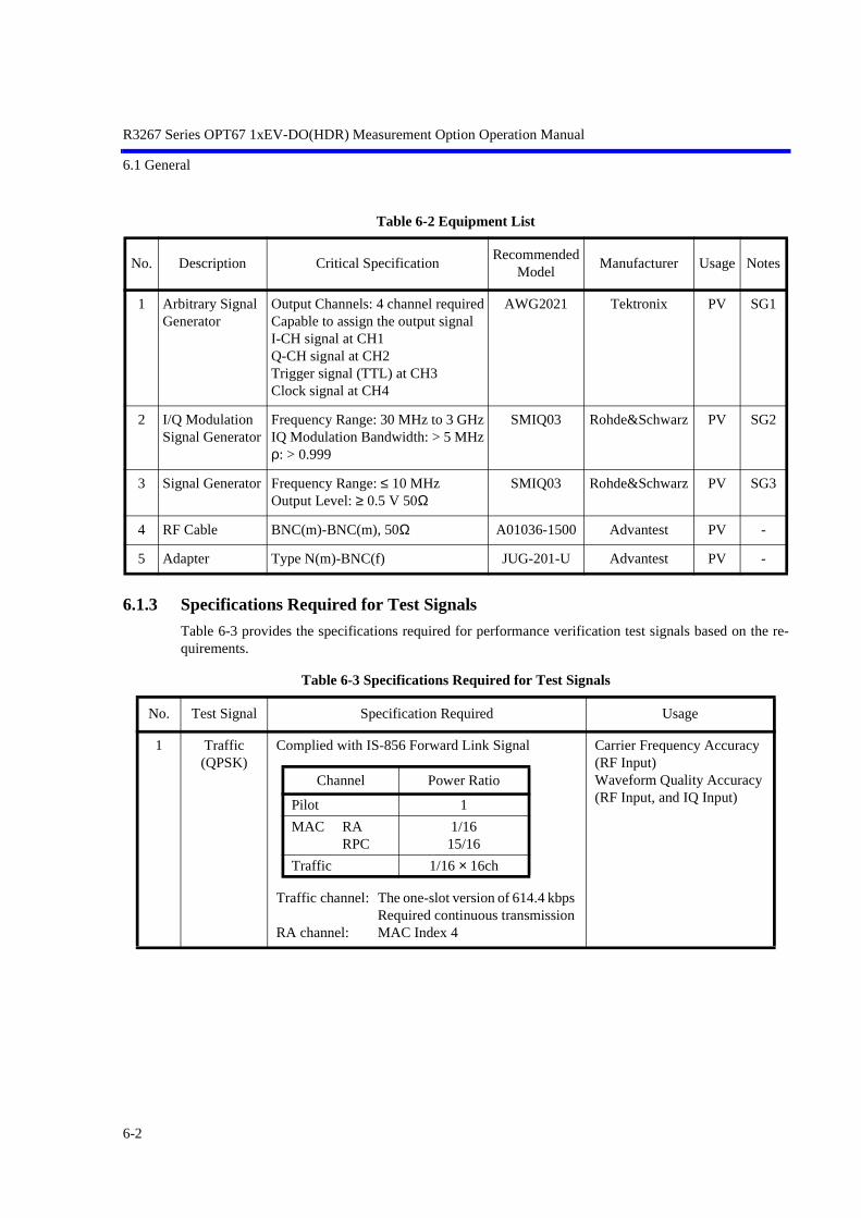
R3267 Series OPT67 1xEV-DO(HDR) Measurement Option Operation Manual
6.1 General
Table 6-2 Equipment List
6.1.3 Specifications Required for Test Signals
Table 6-3 provides the specifications required for performance verification test signals based on the re-quirements.
Table 6-3 Specifications Required for Test Signals
No. Description Critical SpecificationRecommended
ModelManufacturer Usage Notes
1 Arbitrary Signal Generator
Output Channels: 4 channel requiredCapable to assign the output signalI-CH signal at CH1Q-CH signal at CH2Trigger signal (TTL) at CH3Clock signal at CH4
AWG2021 Tektronix PV SG1
2 I/Q Modulation Signal Generator
Frequency Range: 30 MHz to 3 GHzIQ Modulation Bandwidth: > 5 MHzρ: > 0.999
SMIQ03 Rohde&Schwarz PV SG2
3 Signal Generator Frequency Range: ≤ 10 MHzOutput Level: ≥ 0.5 V 50Ω
SMIQ03 Rohde&Schwarz PV SG3
4 RF Cable BNC(m)-BNC(m), 50Ω A01036-1500 Advantest PV -
5 Adapter Type N(m)-BNC(f) JUG-201-U Advantest PV -
No. Test Signal Specification Required Usage
1 Traffic (QPSK)
Complied with IS-856 Forward Link Signal
Traffic channel: The one-slot version of 614.4 kbps Required continuous transmission
RA channel: MAC Index 4
Carrier Frequency Accuracy (RF Input)Waveform Quality Accuracy (RF Input, and IQ Input)
Channel Power Ratio
Pilot 1
MAC RARPC
1/1615/16
Traffic 1/16 × 16ch
6-2

R3267 Series OPT67 1xEV-DO(HDR) Measurement Option Operation Manual
6.1 General
Figure 6-1 shows the timing chart of the trigger signal and the Traffic (QPSK) signal listed in Table 6-3.
Figure 6-1 Timing Chart of Trigger signal and Traffic (QPSK) signal (Not Scaled)
6.1.4 Calibration Cycle
The performance verifications test should be used to check the spectrum analyzer against its specificationsonce a year recommended.
6.1.5 Performance Verification Test Record Sheet
The performance verification test record sheet and performance check record sheet is provided at the endof this chapter. The test record lists test specification and acceptable limits. Recommend that make a copy of this table, record the complete test results on the copy, and keep the copyfor calibration test record. This record could prove invaluable in tracking gradual changes in test result over long periods of the time.
6.1.6 Performance Verification Procedure
Typeface conventions used in this manual.
*Panel keys and soft keys are printed in a contrasting typestyle to make them stand out form the text asfollows:
Panel keys: Boldface type Example: FREQ, FORMAT Soft keys: Boldface and Italic Example: Center, Trace Detector
*When a series of key operations are described using a comma between two keys. *There are various soft menus used to switch between two states such as ON/OFF and AUTO/MNL. For example, when turning off the Display ON/OFF function, the annotation “Display ON/OFF (OFF)”is used. When switching the RBW AUTO/MNL function to MNL, the annotation “RBW AUTO/MNL(MNL)” isused.
6-3

R3267 Series OPT67 1xEV-DO(HDR) Measurement Option Operation Manual
6.2 Performance Verification Test Procedure
6.2 Performance Verification Test Procedure
6.2.1 Code Domain Measurement in RF Input Mode
Description
Test a carrier frequency accuracy, and waveform quality in RF input measurement mode.
Specification
Carrier Frequency Accuracy: ±5 Hz
Waveform Quality (ρ pilot, ρ overall-1, ρ overall-2): ±0.005
Equipment used
Arbitrary Waveform Generator: SG1
IQ Modulation Signal Generator: SG2
Signal Generator: SG3
RF Cable: BNC (m)-BNC (m)
Adapter: Type N (m)-BNC (f)
Setup
Figure 6-2 Setup of Code Domain Measurement (in RF Input)
Procedure
1. Connect equipment as shown in Figure 6-2.
2. On the SG1, set controls to generate the signal complied with No.1 (Traffic) sig-nal listed in Table 6-3 at CH1 and CH2.
3. On the SG1, set controls to generate trigger signal at CH3.
4. On the SG3, set controls to generate clock signal for the SG1-CH4.
6-4

R3267 Series OPT67 1xEV-DO(HDR) Measurement Option Operation Manual
6.2 Performance Verification Test Procedure
5. On the SG2, set controls as follows;
Modulation: External IQ ModulationFrequency: 870.03 MHzOutput Level: 0 dBm
6. On the R3267 Series, set controls as follows;
Center Frequency: 870.03 MHzInput: RF
7. On the R3267 Series, set the measurement parameters as shown in Figure 6-3.
Figure 6-3 Measurement Parameters for Code Domain (RF Input)
8. On the R3267 Series, press DC CAL and AUTO LEVEL to perform dc calibra-tion and auto level.
9. On the R3267 Series, press SINGLE for a single sweep.
10. After the single sweep has completed, record the measurement result in the per-formance verification test record sheet.
6-5

R3267 Series OPT67 1xEV-DO(HDR) Measurement Option Operation Manual
6.2 Performance Verification Test Procedure
6.2.2 Code Domain Measurement in IQ Input Mode
Description
Test a waveform quality in IQ input measurement mode.
Specification
Waveform Quality
(ρ pilot, ρ overall-1, ρ overall-2): ±0.005
Equipment used
Arbitrary Waveform Generator: SG1
Signal Generator: SG3
RF Cable: BNC (m)-BNC (m)
Adapter: Type N (m)-BNC (f)
Setup
Figure 6-4 Setup of Code Domain Measurement (in IQ Input)
Procedure
1. Connect equipment as shown in Figure 6-4.
2. On the SG1, set controls to generate the signal complied with No.1 (Traffic) sig-nal listed in Table 6-3 at CH1 and CH2.
3. On the SG1, set output level to 0.8 Vp-p for CH1, and CH2. Both output signals must be balanced.
4. On the R3267 Series, set controls as follows;
Input: BASEBAND (I&Q)
6-6

R3267 Series OPT67 1xEV-DO(HDR) Measurement Option Operation Manual
6.2 Performance Verification Test Procedure
5. On the R3267 Series, set the measurement parameters as shown in Figure 6-5.
Figure 6-5 Measurement Parameters for Code Domain (IQ Input)
6. On the R3267 Series, press DC CAL to perform dc calibration.
7. On the R3267 Series, press SINGLE for a single sweep.
8. After the single sweep has completed, record the measurement result in the per-formance verification test record sheet.
6-7

R3267 Series OPT67 1xEV-DO(HDR) Measurement Option Operation Manual
6.3 Performance Verification Test Record Sheet
6.3 Performance Verification Test Record Sheet
Performance Verification Test Record SheetModel:OPT3264/3267/3273+67 Date: Serial Number:
(1) Code Domain Measurement in RF Input Mode
(2) Code Domain Measurement in IQ Input Mode
ItemsSpecification Result
Min. Measured Value Max. Pass/Fail
Carrier Frequency Accuracy -5 Hz +5 Hz
Waveform Quality Accuracy ρ pilot 0.995 NA
ρ overall-1 0.995 NA
ρ overall-2 0.995 NA
ItemsSpecification Result
Min. Measured Value Max. Pass/Fail
Waveform Quality Accuracy ρ pilot 0.995 NA
ρ overall-1 0.995 NA
ρ overall-2 0.995 NA
6-8

R3267 Series OPT67 1xEV-DO(HDR) Measurement Option Operation Manual
7 SPECIFICATIONS
7 SPECIFICATIONS
Code Domain measurement
When the following conditional signals (Forward Link) described in IS-856 are measured:
Pilot channel
+ MAC : RA 1ch + RPC 1ch
+ Traffic : Rate 614.4 kbps continuous transmission
• RF input
• IQ input
Characteristics Specification
Measurement frequency range 30 MHz to 3 GHz
Input level range -30dBm to +30 dBm(Total power at ATT:AUTO)
Carrier Frequency Error [Hz]
Measurement accuracy :< ±(Reference frequency accuracy × Carrier frequency + 5 Hz)(Carrier frequency is within a range of ± 500 Hz.)
ρ pilot Residual error: < ± 0.005
ρ overall-1 Residual error: < ± 0.005
ρ overall-2 Residual error: < ± 0.005
Characteristics Specification
Input level range 0.25 VP-P to 0.9 VP-P (± 0.47 V or less)
Input impedance 50 Ω (Nominal), DC coupling, AC coupling
ρ pilot Residual error: < ± 0.005
ρ overall-1 Residual error: < ± 0.005
ρ overall-2 Residual error: < ± 0.005
7-1
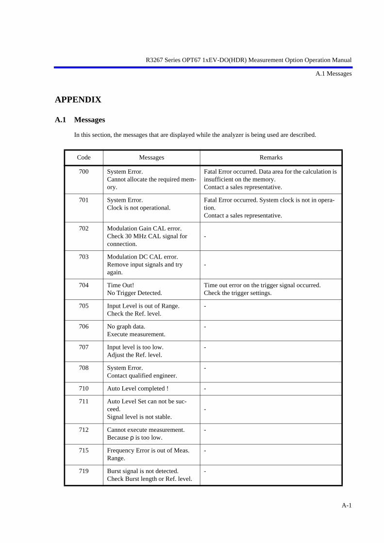
R3267 Series OPT67 1xEV-DO(HDR) Measurement Option Operation Manual
A.1 Messages
APPENDIX
A.1 Messages
In this section, the messages that are displayed while the analyzer is being used are described.
Code Messages Remarks
700 System Error.Cannot allocate the required mem-ory.
Fatal Error occurred. Data area for the calculation is insufficient on the memory.Contact a sales representative.
701 System Error.Clock is not operational.
Fatal Error occurred. System clock is not in opera-tion.Contact a sales representative.
702 Modulation Gain CAL error.Check 30 MHz CAL signal for connection.
-
703 Modulation DC CAL error.Remove input signals and try again.
-
704 Time Out!No Trigger Detected.
Time out error on the trigger signal occurred.Check the trigger settings.
705 Input Level is out of Range.Check the Ref. level.
-
706 No graph data.Execute measurement.
-
707 Input level is too low.Adjust the Ref. level.
-
708 System Error.Contact qualified engineer.
-
710 Auto Level completed ! -
711 Auto Level Set can not be suc-ceed.Signal level is not stable.
-
712 Cannot execute measurement.Because ρ is too low.
-
715 Frequency Error is out of Meas.Range.
-
719 Burst signal is not detected.Check Burst length or Ref. level.
-
A-1

R3267 Series OPT67 1xEV-DO(HDR) Measurement Option Operation Manual
A.1 Messages
721 Modulation Gain CAL error!(#100)Check 30 MHz CAL signal for connection.
-
722 Modulation Gain CAL error!(#200)Check 30 MHz CAL signal for connection.
-
723 Modulation Gain CAL error!(#300)Check 30 MHz CAL signal for connection.
-
724 Modulation Gain CAL error!(#110)Check 30 MHz CAL signal for connection.
-
725 Modulation Gain CAL error!(#120)Check 30 MHz CAL signal for connection.
-
726 Modulation Gain CAL error!(#210)Check 30 MHz CAL signal for connection.
-
727 Modulation Gain CAL error!(#220)Check 30 MHz CAL signal for connection.
-
728 Modulation Gain CAL error!(#310)Check 30 MHz CAL signal for connection.
-
729 Modulation Gain CAL error!(#320)Check 30 MHz CAL signal for connection.
-
744 No Idle Slot within a frame.Check the input signal.
No Idle Slot exists in a frame.
745 No Active Slot within a frame.Check the input signal.
No Active Slot exists in a frame.
Code Messages Remarks
A-2
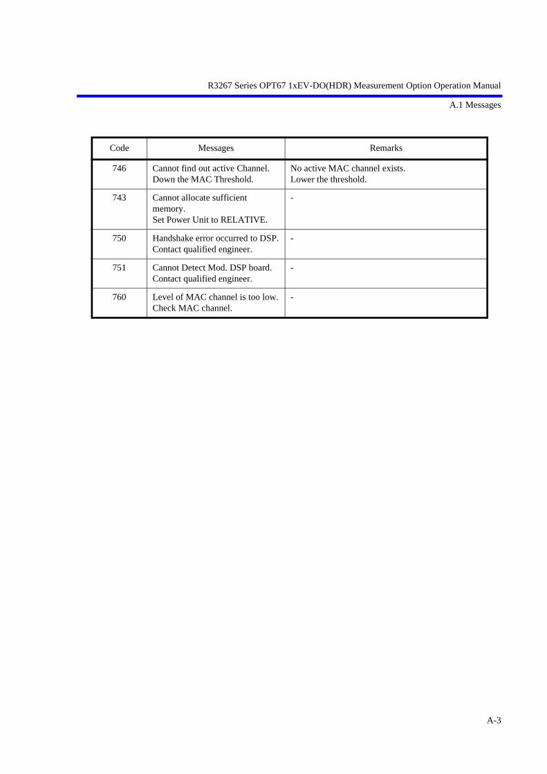
R3267 Series OPT67 1xEV-DO(HDR) Measurement Option Operation Manual
A.1 Messages
746 Cannot find out active Channel.Down the MAC Threshold.
No active MAC channel exists.Lower the threshold.
743 Cannot allocate sufficient memory.Set Power Unit to RELATIVE.
-
750 Handshake error occurred to DSP.Contact qualified engineer.
-
751 Cannot Detect Mod. DSP board.Contact qualified engineer.
-
760 Level of MAC channel is too low.Check MAC channel.
-
Code Messages Remarks
A-3
R3267 Series OPT67 1xEV-DO(HDR) Measurement Option Operation Manual
ALPHABETICAL INDEX
ALPHABETICAL INDEX ALPHABETICAL INDEX
[A]About Complementary Filter .................. 5-8About Equalizing Filter .......................... 5-9Accessories ............................................. 1-1Auto Level Set ........................................ 3-6, 3-7,
3-8, 3-9, 3-10, 3-11, 3-12, 3-13, 3-14, 3-15, 3-16, 3-17, 3-18, 3-19, 3-22, 3-25, 3-28, 3-31, 3-34, 3-35, 3-38, 3-43, 3-46, 3-49, 3-51, 3-53, 3-55, 3-56, 3-57, 3-59, 3-60
Average Mode ......................................... 3-6, 3-7, 3-8, 3-9, 3-10, 3-11, 3-12, 3-13, 3-14, 3-15, 3-24, 3-27, 3-30, 3-33, 3-35, 3-38, 3-42, 3-45, 3-48, 3-50
Average Times ON/OFF ......................... 3-6, 3-7, 3-8, 3-9, 3-10, 3-11, 3-12, 3-13, 3-14, 3-15, 3-17, 3-18, 3-19, 3-24, 3-26, 3-29, 3-33, 3-34, 3-36, 3-40, 3-44, 3-47, 3-49, 3-56, 3-58, 3-60, 3-61
[B]Band Class .............................................. 3-19, 3-61Band Conversion ..................................... 3-14Bandpass Filter ....................................... 3-18, 3-58,
3-59Baseband Input ....................................... 3-19, 3-62
Block Diagram ........................................ 5-10
[C]Calibration .............................................. 1-1Calibration Cycle .................................... 6-3CCDF ...................................................... 3-5, 3-17,
3-56CCDF Measurement ............................... 2-12Channel Setting ....................................... 3-19, 3-61,
3-62Code ........................................................ A-1Code Domain .......................................... 3-5Code Domain Measurement in RF Input Mode ....................................................... 6-4Communication Systems ........................ 3-21Complementary Filter Rolloff ................ 3-16, 3-52,
3-53Config ..................................................... 3-6, 3-7,
3-8, 3-9, 3-10, 3-11, 3-12, 3-13, 3-14, 3-15, 3-24, 3-26, 3-29, 3-33, 3-34, 3-36, 3-41, 3-44, 3-47, 3-50
Connectors .............................................. 1-1Cont Auto Level Set ............................... 3-19, 3-63Copy from STD ...................................... 3-6, 3-11,
3-12, 3-13, 3-14, 3-15, 3-19, 3-23, 3-36, 3-40, 3-43, 3-46, 3-49, 3-61
[D]Data Code Domain .................................. 3-16, 3-51Data Despread Constellation .................. 3-16, 3-52DC CAL .................................................. 3-19, 3-61Delay Time ............................................. 3-6, 3-7,
3-8, 3-9, 3-12, 3-23, 3-26, 3-28, 3-32, 3-39
Delete ...................................................... 3-15Delete Line .............................................. 3-6, 3-8,
3-11, 3-12, 3-13, 3-14,
I-1

R3267 Series OPT67 1xEV-DO(HDR) Measurement Option Operation Manual
Alphabetical Index
3-23, 3-29, 3-36, 3-40, 3-43, 3-46, 3-47, 3-49
Detector ................................................... 3-6, 3-7, 3-8, 3-9, 3-10, 3-11, 3-12, 3-13, 3-14, 3-15, 3-24, 3-27, 3-29, 3-32, 3-33, 3-34, 3-37, 3-40, 3-41, 3-44, 3-47, 3-50
Display Unit ............................................ 3-6, 3-7, 3-8, 3-9, 3-11, 3-12, 3-13, 3-14, 3-15, 3-24, 3-27, 3-29, 3-33, 3-37, 3-41, 3-45, 3-48, 3-50
Due to Modulation .................................. 3-5, 3-38, 5-4, 5-5
Due to Transient ...................................... 3-5, 3-35, 5-4, 5-5
[E]Edit Table 1 2 3 ....................................... 3-19, 3-61Edit Table 4 5 6 ....................................... 3-19, 3-61Edit Table 7 8 9 ....................................... 3-19, 3-61Equalizing Filter ..................................... 3-16, 3-52,
3-54Ext Gate .................................................. 3-9, 3-12,
3-32, 3-39EXT Trigger Delay ................................. 3-17, 3-56EXT Trigger Slope .................................. 3-16, 3-17,
3-18, 3-53, 3-54, 3-55, 3-58, 3-60
[F]F-Domain ................................................ 3-5, 3-31Frame Analysis ....................................... 3-5, 3-16Freq. Setting ............................................ 3-11, 3-12,
3-13, 3-14, 3-37, 3-41, 3-44, 3-47
Frequency Input ...................................... 3-19, 3-62Functional Description ............................ 3-20
I-2
[G]Gate Position ........................................... 3-9, 3-12,
3-32, 3-39Gate Setup ............................................... 3-9, 3-12,
3-31, 3-32, 3-38, 3-39
Gate Source ............................................. 3-9, 3-12, 3-32, 3-39
Gate Width .............................................. 3-9, 3-12, 3-32, 3-39
Gated Sweep ........................................... 3-9, 3-33Gated Sweep ON/OFF ............................ 3-9, 3-12,
3-32, 3-39General .................................................... 6-1GPIB Command Codes ........................... 4-9GPIB Command Index ............................ 4-1Graph Type ............................................. 3-16, 3-51
[ I ]Ich & Qch Time ...................................... 3-19Ich Time & FFT ...................................... 3-19Inband Spurious ...................................... 5-4, 5-6Inband Spurious Modes .......................... 5-5Inband Spurious(1) ................................. 3-5, 3-43Inband Spurious(2) ................................. 3-5, 3-46Input ........................................................ 3-19, 3-62Insert Line ............................................... 3-6, 3-8,
3-11, 3-12, 3-13, 3-14, 3-15, 3-23, 3-29, 3-36, 3-40, 3-43, 3-46, 3-49
Integral Band ........................................... 3-14, 3-48INTRODUCTION .................................. 1-1Introduction ............................................. 6-1IQ Complex FFT ..................................... 3-19IQ Inverse ............................................... 3-19, 3-62
[J]Judgment ................................................. 3-6, 3-7,
3-8, 3-9, 3-10, 3-11, 3-12, 3-13, 3-14, 3-15, 3-24, 3-27, 3-30, 3-33, 3-34, 3-37, 3-42, 3-45, 3-48, 3-50

R3267 Series OPT67 1xEV-DO(HDR) Measurement Option Operation Manual
Alphabetical Index
[L]Load Table .............................................. 3-8, 3-15,
3-29, 3-49Lower Limit ............................................ 3-6, 3-9,
3-10, 3-24, 3-33, 3-35
[M]MAC Code Domain ................................ 3-16, 3-51MAC Threshold ...................................... 3-16, 3-53,
3-54Margin ∆X ON/OFF ............................... 3-11, 3-12,
3-13, 3-14, 3-36, 3-40, 3-43, 3-46
Marker Edit ............................................. 3-11, 3-12, 3-13, 3-14, 3-36, 3-40, 3-43, 3-46
Marker Edit Function .............................. 5-4Meas Length ........................................... 3-17, 3-57MEASUREMENT EXAMPLES ............ 2-1Measuring the Code Domain Power of Base Station Signals ................................ 2-1Measuring the Frame Analysis of Access Network Signals ......................... 2-8Menu Index ............................................. 3-1Menu Map ............................................... 3-5Messages ................................................. A-1Modulation .............................................. 3-5Multiplier ................................................ 3-8, 3-29
[O]OBW ....................................................... 3-5, 3-34OBW% .................................................... 3-10, 3-34OFF Position ........................................... 3-7, 3-26OFF Width .............................................. 3-7, 3-26Offset Level ............................................ 3-19, 3-62ON Position ............................................. 3-7, 3-26ON Width ................................................ 3-7, 3-26ON/OFF Ratio ......................................... 3-5, 3-7,
3-25Outband Spurious ................................... 3-5, 3-49
[P]Parameter Setup ...................................... 3-6, 3-7,
3-8, 3-9, 3-10, 3-11, 3-12, 3-13, 3-14, 3-15, 3-16, 3-17,
3-18, 3-19, 3-24, 3-27, 3-29, 3-33, 3-34, 3-36, 3-41, 3-44, 3-47, 3-50, 3-52, 3-53, 3-55, 3-57, 3-58, 3-59, 3-60
Peak Factor of Tx Power ........................ 5-7Peak MKR Y Delta ................................. 3-8, 3-13,
3-14, 3-15, 3-29, 3-44, 3-47, 3-50
Performance Verification Procedure ...... 6-3PERFORMANCE VERIFICATION TEST ....................................................... 6-1Performance Verification Test Procedure ................................................ 6-4Performance Verification Test Record Sheet ........................................................ 6-3Phase Error(Pilot) ................................... 3-16, 3-52Pilot Constellation ................................... 3-16, 3-52Pilot/MAC Channel Power ..................... 3-5, 3-18PN Offset ................................................ 3-16, 3-18,
3-53, 3-54, 3-58, 3-59
Power ...................................................... 3-5, 3-17, 3-18, 3-55
Power (F-Domain) .................................. 3-31Power (T-Domain) .................................. 3-22Power Unit .............................................. 3-17, 3-56Preselector ............................................... 3-8, 3-15,
3-30, 3-50Product Overview ................................... 1-1
[Q]Qch Time & FFT .................................... 3-19
[R]Ref Power ............................................... 3-11, 3-12,
3-13, 3-14, 3-37, 3-41, 3-44, 3-47
REFERENCE .......................................... 3-1REMOTE CONTROL ............................ 4-1Result ...................................................... 3-8, 3-11,
3-12, 3-13, 3-14, 3-29, 3-37, 3-41, 3-44, 3-47
I-3

R3267 Series OPT67 1xEV-DO(HDR) Measurement Option Operation Manual
Alphabetical Index
Rolloff Factor .......................................... 3-11, 3-12, 3-37, 3-42
[S]Save Table ............................................... 3-8, 3-15,
3-29, 3-49Scale Setup .............................................. 3-17, 3-56Select Type ............................................. 3-19, 3-60Self Test Function ................................... 1-1Set to Default .......................................... 3-8, 3-15,
3-30, 3-50Set to STD ............................................... 3-6, 3-7,
3-9, 3-10, 3-11, 3-12, 3-13, 3-14, 3-23, 3-25, 3-26, 3-27, 3-32, 3-34, 3-35, 3-38, 3-39, 3-42, 3-45, 3-49
Shift X ..................................................... 3-6, 3-11, 3-12, 3-13, 3-14, 3-23, 3-35, 3-40, 3-43, 3-46
Shift Y ..................................................... 3-6, 3-11, 3-12, 3-13, 3-14, 3-23, 3-35, 3-40, 3-43, 3-46
Signal Type ............................................. 3-19, 3-62Slope ....................................................... 3-6, 3-7,
3-8, 3-9, 3-12, 3-22, 3-26, 3-28, 3-31, 3-39
Sort .......................................................... 3-6, 3-11, 3-12, 3-13, 3-14, 3-24, 3-36, 3-40, 3-43, 3-46, 3-47
SPECIFICATIONS ................................. 7-1Specifications Required for Test Signals 6-2Spurious .................................................. 3-5Spurious (T-Domain) .............................. 3-28Start Offset .............................................. 3-14, 3-48STD ......................................................... 3-5, 3-19,
3-61STD Setup ............................................... 3-19, 3-61STD Template ......................................... 3-18, 3-57,
3-59
I-4
Stop Offset .............................................. 3-14, 3-48Symbol Rate 1/T ..................................... 3-11, 3-12,
3-37, 3-42
[T]Table Edit ................................................ 3-8, 3-15,
3-29, 3-49Table Init ................................................. 3-6, 3-8,
3-11, 3-12, 3-13, 3-14, 3-15, 3-24, 3-29, 3-36, 3-40, 3-43, 3-44, 3-46, 3-47, 3-49
Table No. 1/2/3 ....................................... 3-8, 3-15, 3-28, 3-29, 3-49
T-Domain ................................................ 3-5, 3-22TECHNICAL INFORMATION ............. 5-1Template ................................................. 3-6, 3-11,
3-12, 3-13, 3-14, 3-23, 3-35, 3-40, 3-43, 3-46
Template Couple to Power ..................... 3-6, 3-11, 3-12, 3-13, 3-14, 3-24, 3-37, 3-42, 3-45, 3-48
Template Edit .......................................... 3-6, 3-11, 3-12, 3-13, 3-14, 3-23, 3-36, 3-40, 3-43, 3-46
Template Edit function ........................... 5-1Template Entry ....................................... 3-18, 3-57,
3-59Template Limit ....................................... 3-6, 3-11,
3-12, 3-13, 3-14, 3-24, 3-37, 3-42, 3-45, 3-48
Template ON/OFF .................................. 3-6, 3-12, 3-13, 3-14, 3-23, 3-35, 3-40, 3-43, 3-46
Template Setting in the F-Domain Measuring Mode .............. 5-3Template Setting in the T-Domain Measuring Mode ............. 5-1Template UP/LOW ................................. 3-6, 3-23

R3267 Series OPT67 1xEV-DO(HDR) Measurement Option Operation Manual
Alphabetical Index
Test Equipment ....................................... 6-1Time & FFT ............................................ 3-5, 3-19,
3-60Total Power ............................................. 3-5, 3-18Trace Write ON/OFF .............................. 3-17, 3-57Trigger .................................................... 3-9, 3-12,
3-32, 3-39Trigger Delay .......................................... 3-17, 3-19,
3-57, 3-61Trigger Level .......................................... 3-6, 3-7,
3-8, 3-9, 3-12, 3-17, 3-19, 3-23, 3-26, 3-28, 3-31, 3-39, 3-55, 3-61
Trigger Mode .......................................... 3-17, 3-57Trigger Position ...................................... 3-6, 3-7,
3-8, 3-9, 3-12, 3-23, 3-26, 3-28, 3-32, 3-39
Trigger Setup .......................................... 3-6, 3-7, 3-8, 3-9, 3-12, 3-22, 3-25, 3-28, 3-31, 3-38
Trigger Slope .......................................... 3-17, 3-19, 3-57, 3-61
Trigger Source ........................................ 3-6, 3-7, 3-8, 3-9, 3-12, 3-16, 3-17, 3-18, 3-19, 3-22, 3-25, 3-28, 3-31, 3-38, 3-53, 3-54, 3-55, 3-58, 3-59, 3-60
Trigger Source INTRVL (EXT) and INTRVL .................................................. 5-7Tx Power ................................................. 3-5, 3-17,
3-55
[U]Upper Limit ............................................. 3-6, 3-7,
3-9, 3-10, 3-24, 3-27, 3-33, 3-35
USER Template ...................................... 3-18, 3-57, 3-59
[W]Window ON/OFF ................................... 3-6, 3-7,
3-9, 3-23, 3-26, 3-32
Window Position ..................................... 3-6, 3-9, 3-23, 3-32
Window Setup ......................................... 3-6, 3-7, 3-9, 3-23, 3-26, 3-32
Window Width ........................................ 3-6, 3-9, 3-23, 3-33
[X]X Scale Max ............................................ 3-17, 3-56X Scale Range ......................................... 3-17, 3-56
[Y]Y [dB/div] 10/5 ....................................... 3-18, 3-57Y Scale [dB/div] 10/5/2 .......................... 3-6, 3-7,
3-9, 3-24, 3-26, 3-33
I-5

IMPORTANT INFORMATION FOR ADVANTEST SOFTWARE
PLEASE READ CAREFULLY: This is an important notice for the software defined herein. Computer programs
including any additions, modifications and updates thereof, operation manuals, and related materials provided by
ADVANTEST (hereafter referred to as "SOFTWARE"), included in or used with hardware produced by
ADVANTEST (hereafter referred to as "PRODUCTS").
SOFTWARE License
All rights in and to the SOFTWARE (including, but not limited to, copyright) shall be and remain vested in
ADVANTEST. ADVANTEST hereby grants you a license to use the SOFTWARE only on or with ADVANTEST
PRODUCTS.
Restrictions
(1) You may not use the SOFTWARE for any purpose other than for the use of the PRODUCTS.
(2) You may not copy, modify, or change, all or any part of, the SOFTWARE without permission from
ADVANTEST.
(3) You may not reverse engineer, de-compile, or disassemble, all or any part of, the SOFTWARE.
Liability
ADVANTEST shall have no liability (1) for any PRODUCT failures, which may arise out of any misuse
(misuse is deemed to be use of the SOFTWARE for purposes other than it's intended use) of the SOFTWARE.
(2) For any dispute between you and any third party for any reason whatsoever including, but not limited to,
infringement of intellectual property rights.

LIMITED WARRANTY
1. Unless otherwise specifically agreed by Seller and Purchaser in writing, ADVANTEST will warrant to thePurchaser that during the Warranty Period this Product (other than consumables included in the Product) willbe free from defects in material and workmanship and shall conform to the specifications set forth in thisOperation Manual.
2. The warranty period for the Product (the "Warranty Period") will be a period of one year commencing on thedelivery date of the Product.
3. If the Product is found to be defective during the Warranty Period, ADVANTEST will, at its option and in itssole and absolute discretion, either (a) repair the defective Product or part or component thereof or (b) replacethe defective Product or part or component thereof, in either case at ADVANTEST
,s sole cost and expense.
4. This limited warranty will not apply to defects or damage to the Product or any part or component thereofresulting from any of the following:
(a) any modifications, maintenance or repairs other than modifications, maintenance or repairs (i) performedby ADVANTEST or (ii) specifically recommended or authorized by ADVANTEST and performed inaccordance with ADVANTEST
,s instructions;
(b) any improper or inadequate handling, carriage or storage of the Product by the Purchaser or any thirdparty (other than ADVANTEST or its agents);
(c) use of the Product under operating conditions or environments different than those specified in theOperation Manual or recommended by ADVANTEST, including, without limitation, (i) instances wherethe Product has been subjected to physical stress or electrical voltage exceeding the permissible range and(ii) instances where the corrosion of electrical circuits or other deterioration was accelerated by exposureto corrosive gases or dusty environments;
(d) use of the Product in connection with software, interfaces, products or parts other than software,interfaces, products or parts supplied or recommended by ADVANTEST;
(e) the occurrence of an event of force majeure, including, without limitation, fire, explosion, geologicalchange, storm, flood, earthquake, tidal wave, lightning or act of war; or
(f) any negligent act or omission of the Purchaser or any third party other than ADVANTEST.
5. EXCEPT TO THE EXTENT EXPRESSLY PROVIDED HEREIN, ADVANTEST HEREBY EXPRESSLYDISCLAIMS, AND THE PURCHASER HEREBY WAIVES, ALL WARRANTIES, WHETHER EXPRESSOR IMPLIED, STATUTORY OR OTHERWISE, INCLUDING, WITHOUT LIMITATION, (A) ANYWARRANTY OF MERCHANTABILITY OR FITNESS FOR A PARTICULAR PURPOSE AND (B) ANYWARRANTY OR REPRESENTATION AS TO THE VALIDITY, SCOPE, EFFECTIVENESS ORUSEFULNESS OF ANY TECHNOLOGY OR ANY INVENTION.
6. THE REMEDY SET FORTH HEREIN SHALL BE THE SOLE AND EXCLUSIVE REMEDY OFTHE PURCHASER FOR BREACH OF WARRANTY WITH RESPECT TO THE PRODUCT.
7. ADVANTEST WILL NOT HAVE ANY LIABILITY TO THE PURCHASER FOR ANY INDIRECT,INCIDENTAL, SPECIAL, CONSEQUENTIAL OR PUNITIVE DAMAGES, INCLUDING,WITHOUT LIMITATION, LOSS OF ANTICIPATED PROFITS OR REVENUES, IN ANY ANDALL CIRCUMSTANCES, EVEN IF ADVANTEST HAS BEEN ADVISED OF THE POSSIBILITYOF SUCH DAMAGES AND WHETHER ARISING OUT OF BREACH OF CONTRACT,WARRANTY, TORT (INCLUDING, WITHOUT LIMITATION, NEGLIGENCE), STRICTLIABILITY, INDEMNITY, CONTRIBUTION OR OTHERWISE.

CUSTOMER SERVICE DESCRIPTIONIn order to maintain safe and trouble-free operation of the Product and to prevent the incurrence of unnecessarycosts and expenses, ADVANTEST recommends a regular preventive maintenance program under its maintenanceagreement.
ADVANTEST,s maintenance agreement provides the Purchaser on-site and off-site maintenance, parts,
maintenance machinery, regular inspections, and telephone support and will last a maximum of ten years fromthe date the delivery of the Product. For specific details of the services provided under the maintenanceagreement, please contact the nearest ADVANTEST office listed at the end of this Operation Manual orADVANTEST
,s sales representatives.
Some of the components and parts of this Product have a limited operating life (such as, electrical andmechanical parts, fan motors, unit power supply, etc.). Accordingly, these components and parts will have to bereplaced on a periodic basis. If the operating life of a component or part has expired and such component or parthas not been replaced, there is a possibility that the Product will not perform properly. Additionally, if theoperating life of a component or part has expired and continued use of such component or part damages theProduct, the Product may not be repairable. Please contact the nearest ADVANTEST office listed at the end ofthis Operation Manual or ADVANTEST
,s sales representatives to determine the operating life of a specific
component or part, as the operating life may vary depending on various factors such as operating condition andusage environment.
CLAIM FOR DAMAGE IN SHIPMENT TO ORIGINAL BUYERThe product should be thoroughly inspected immediately upon original delivery to buyer. All material in thecontainer should be checked against the enclosed packing list or the instruction manual alternatively.ADVANTEST will not be responsible for shortage unless notified immediately.If the product is damaged in any way, a claim should be filed by the buyer with carrier immediately. (Toobtain a quotation to repair shipment damage, contact ADVANTEST or the local supplier.) Final claim andnegotiations with the carrier must be completed by buyer.

SALES & SUPPORT OFFICES Advantest America Measuring Solutions, Inc. (North America)
New Jersey Office258 Fernwood Avenue, Edison, NJ 08837Phone: (1) (732) 346-2600 Facsimile: (1) (732) 346-2610
Santa Clara Office3201 Scott Blvd., Santa Clara, CA 95054Phone: (1) (408) 988-7700 Facsimile: (1) (408) 987-0688
ROHDE & SCHWARZ Engineering and Sales GmbH (Europe)Mühldorfstraße 15, D-81671 München, GermanyP.O.B. 80 14 29, D-81614 München, GermanyPhone: (49) (89) 4129-13711 Facsimile: (49) (89) 4129-13723
Advantest (Singapore) Pte. Ltd. (Singapore)438A Alexandra Road, #8-03/06Alexandra Technopark, Singapore 119967Phone: (65) (6) 274-3100 Facsimile: (65) (6) 274-4055
Advantest Korea Co., Ltd. (Korea)16Fl., MIRAEWASARAM Bldg., 942-1Daechi-Dong, Kangnam-Ku, Seoul, KoreaPhone: (82) (02) 3452-7710 Facsimile: (82) (02) 3452-7970
Advantest (Suzhou) Co., Ltd. (China)5F, No. 46 Factory Building,No. 555 Gui Ping Road, Shanghai, China 200233Phone: (86) (21) 6485-2725 Facsimile: (86) (21) 6485-2726
Shinjuku-NS Building, 4-1, Nishi-Shinjuku 2-chome, Shinjuku-ku, Tokyo 163-0880, JapanPhone:+81-3-3342-7500 Facsimile:+81-3-5322-7270 Telex:232-4914 ADVAN J
Technology Support on the Leading Edge