R2KA 24 /8 - Produzione Caldaie murali: caldaie a ... · 2 r2ka 24 /8 - rad - ing - manuale -...
76
R2KA 24 /8 - RAD - ING - Manuale - 1507.1 Installation, Use and Maintenance Manual for model 0694 R2KA 24 /8 Condensing boiler with integrated heat exchanger for domestic hot water side and storage
Transcript of R2KA 24 /8 - Produzione Caldaie murali: caldaie a ... · 2 r2ka 24 /8 - rad - ing - manuale -...

R2KA 24 /8 - RAD - ING - Manuale - 1507.1
Installation, Use and Maintenance Manual for model
0694
R2KA 24 /8
Condensing boiler with integrated heat
exchanger for domestic hot water side
and storage
2R2KA 24 /8 - RAD - ING - Manuale - 1507.1
R2K
A 24.8_
EN
SUMMARY
SUMMARY
INTRODUCTION 4
1. INSTALLER SECTION 7
1.1. INSTALLATION 81.1.1. GENERAL INSTALLATION WARNINGS 81.1.2. BOILER LOCATION ENVIRONMENTAL REQUIREMENTS 81.1.3. REFERENCE LEGISLATION 91.1.4. UNPACKING 101.1.5. OVERALL DIMENSIONS 111.1.6. JIG 111.1.7. POSITIONING AND MINIMAL TECHNICAL SPACES 121.1.8. CIRCULATOR PREVALENCE/FLOW DIAGRAM 131.1.9. HYDRAULIC CONNECTION 141.1.10. D.H.W. CIRCULATING LOOP 151.1.11. SYSTEM FILLING 161.1.12. FILLING THE CONDENSATE COLLECTION SIPHON 171.1.13. ANTI-FREEZE PROTECTION 181.1.14. GAS CONNECTION 191.1.15. ELECTRICAL CONNECTION 191.1.16. POWER SUPPLY 201.1.17. OPTIONAL ELECTRICAL CONNECTIONS 211.1.18. FUME EXHAUST FITTINGS 231.1.19. INSTALLATION MODES (IN ACCORDANCE WITH UNI 10642) 241.1.20. TYPES OF FUME EXHAUST SYSTEMS 26
2. SUPPORT CENTRE SECTION 29
2.1. FIRST START-UP 302.1.1. PRELIMINARY OPERATIONS FOR FIRST START-UP 302.1.2. BOILER COMMISSIONING 312.1.3. CO2 VALUE CHECK AND CALIBRATION 322.1.4. ACCESSING AND PROGRAMMING THE PARAMETERS 332.1.5. DIGITECH CS PARAMETERS TABLE 352.1.6. ELECTRIC FAN FREQUENCY/HEAT CAPACITY DIAGRAM 42
2.2. MAINTENANCE 432.2.7. GENERAL MAINTENANCE WARNINGS 432.2.8. TECHNICAL DATA 452.2.9. TECHNICAL ASSEMBLY 472.2.10. HYDRAULIC BOARD 482.2.11. 3-WAY VALVE OPERATION 49

3R2KA 24 /8 - RAD - ING - Manuale - 1507.1
R2K
A 24.8_
EN
SUMMARY
2.2.12. WIRING DIAGRAM 502.2.13. ACCESSING THE BOILER 512.2.14. ACCESSING THE ELECTRONIC BOARD 522.2.15. SYSTEM EMPTYING 532.2.16. BOILER MAINTENANCE 542.2.17. FAULT SIGNALLING CODES 552.2.18. ACTIVE FUNCTIONS SIGNALLING CODES 582.2.19. GAS TYPE TRANSFORMATION 59
3. USER SECTION 61
3.1. USE 623.1.1. GENERAL USE WARNINGS 623.1.2. CONTROL PANEL 633.1.3. DISPLAY ICONS 643.1.4. INFO MENU DISPLAY DATA 653.1.5. START-UP 663.1.6. OPERATING MODE 663.1.7. INFORMATIONAL NOTE ON ANTI-FREZZE FUNCTION 673.1.8. SYSTEM FILLING 683.1.9. FAULT SIGNALLING CODES 693.1.10. ACTIVE FUNCTIONS SIGNALLING CODES 713.1.11. MAINTENANCE 723.1.12. COVER CLEANING 723.1.13. DISPOSAL 72

4R2KA 24 /8 - RAD - ING - Manuale - 1507.1
_P
refazione_EN
2.
INTRODUCTION
WARNING
Before starting any operation it is mandatory to read this instruction manual, in relation to the activities to be carried out as described in each relevant section. Proper operation and optimal performance of the boiler are ensured by strict compliance with all the instructions given in this manual.
The installation, use and maintenance manual is an integral and essential part of the product and must be delivered to the user.
MANUAL USERS
The manual users are all those who install, use and maintain the boiler.
The boiler must be used and accessed only by qualified operators that fully read and understood the use and maintenance manual, paying particular attention to the warnings.
READING AND SYMBOLS OF THE MANUAL
To ease the understanding of this manual, recurrent symbols where used, in particular:
› On the outer margin of the page is placed a thumb index indicating the type of user to which the instructions in that section address.
› The titles are differentiated by thickness and size in accordance with their hierarchy.
› The images contain important parts described in the text, marked with numbers or letters.
› (See chap “chapter name”): this entry indicates another section in the Manual that you should refer to.
› Device: this term is used referring to the boiler.
DANGERIt identifies an information related to a
general danger that if not complied with, may cause serious personal damage or even death.
ATTENTIONIt identifies an information that if not
complied with may cause small or medium level lesions to the person or serious deterioration to the boiler.
WARNINGIt identifies a precaution information that
must be observed in order to avoid damaging the machine or parts of it.
MANUAL STORAGE
The manual must be carefully stored and replaced in case of deterioration and/or low legibility.
If you misplace the use and maintenance manual, you can request it from the Technical Support Centre giving the serial number and model of the boiler indicated on the plate placed on the right side of its casing.
As an alternative, the use and maintenance manual can be downloaded free from the on-line site www.radiant.it, accessing the “download” section and entering the boiler model.
INTRODUCTION

5R2KA 24 /8 - RAD - ING - Manuale - 1507.1
_P
refazione_EN
2.
MANUFACTURER WARRANTY AND RESPONSIBILITY
The warranty of the Manufacturer is provided only through its own authorized Technical Support Centres, listed for each Region and Provence on the site www.radiant.it, and covers all conformity defects at the moment of sale.
The technical and functional features of the device are ensured by its use in compliance:
1. with the use and maintenance instructions contained in the manuals accompanying the product, the content of which the customer certifies that he is aware;
2. with the conditions and purposes to which assets of the same type are intended.
For more information on the warranty validity, its duration, the obligations and the exemptions, please consult the First start-up certificate attached to this manual.
The manufacturer reserves:
› the right to modify the tools and relative technical documentation without any obligation to third parties;
› the material and intellectual ownership of this manual and forbids its distribution and duplication, even partial, without prior written authorization.
PRODUCT CONFORMITY
RADIANT BRUCIATORI spa with reference to art. 5 of DPR n 447 dated 06/12/1991, “Regulation implementing of law 5 March 1990, n 46” and in compliance with law 6 December 1971, n 1083 “Safety standards for the use of fuel gas”, declares that its gas boilers are professionally manufactured.
All boilers obtained their CE certification (D.M. 2 April 1998 regulation implementing art.32 Law 10/91) and comply, from technical and functional point of view with the requirements provided in standards:
› UNI-CIG 7129/08
› UNI EN 297 for B-TYPE GAS DEVICES WITH HEAT CAPACITY 70 kW
› EN 483 for C-TYPE GAS DEVICES WITH HEAT CAPACITY 70 kW
› UNI EN 677 for CONDENSING GAS DEVICES WITH HEAT CAPACITY 70 kW
› Performance at 100% Pn and 30% (partial load Pn) - D.P.R. 412/93 (regulation implementing Law 10/91 art. 4, paragraph 4) and subsequent modifications
The gas boilers also comply with the directives below:
› GAS DIRECTIVE 2009/142/CE
› PERFORMANCE DIRECTIVE 92/42 CEE
› ELECTROMAGNETIC COMPATIBILITY DIRECTIVE 2004/108/CE
› LOW VOLTAGE DIRECTIVE 2006/95/CEE
The materials used such as copper, brass, stainless steel create a homogeneous, compact and functional assembly, easy to install and manage. In its simplicity, the boiler is equipped with all accessories necessary to render it a veritable independent heating unit. All boilers are tested and delivered with a quality certificate signed by the tester.
INTRODUCTION


The installation operations described in this section should
be performed only by qualified personnel, having the
appropriate technical training in the field for the installation
and maintenance of components of civil and industrial
domestic hot water production and heating plants as
provided by art. 3 of D.M. n°37 dated 22.01.2008.
1. INSTALLER SECTION

8R2KA 24 /8 - RAD - ING - Manuale - 1507.1
1 Avvertenze generali per l'installazione_Locale caldaia_EN
1. INSTALLATION
INS
TALLE
R
1.1. INSTALLATION
1.1.1. GENERAL INSTALLATION WARNINGS
WARNINGThis machine may be used only for the
purpose for which it has been designed: heat water to a temperature below boiling point at atmospheric pressure. Any other use is considered wrong and dangerous. The manufacturer is excluded from any contractual or out of contract responsibility for damage caused to people, animals or property due to errors during installation.
WARNINGThis boiler should be installed only
by qualified personnel, having the appropriate technical training in the field for the installation and maintenance of components of civil and industrial domestic hot water production and heating plants as provided by art. 3 of D.M. n°37 dated 22.01.2008.
WARNINGAfter having removed the packing, make
sure the equipment is intact. In case of doubt, do not use the equipment and contact the supplier.
BEFORE INSTALLING THE BOILER, THE INSTALLER MUST MAKE SURE THAT THE FOLLOWING CONDITIONS ARE MET:
› The device is connected to a heating plant and a water supply network appropriate for its power and performance.
› The location must be properly vented through an air vent.
The air vent must be placed at floor level to prevent it from being obstructed, protected by a grid that does not hamper the useful section of passage.
› The device is suitable for use with the type of gas available by checking the boiler data plate (placed on the inner side of the front casing.
› Make sure that the tubes and couplings are perfectly sealed, without any gas leaks.
› Make sure that the grounding system works properly.
› Make sure that the electrical systems is suitable for the maximum power absorbed by the equipment, value indicated on the data plate.
WARNINGUse only original RADIANT optional or kit
accessories (including electrical).
1.1.2. BOILER LOCATION ENVIRONMENTAL REQUIREMENTS
Two devices intended for the same use in the same location or in directly communicating locations, generating a total heat capacity of over 35 kW, represent a heating unit, subjected to the requirements provided by D.M. n°74 dated 12.04.1996 “Approval of the fire prevention technical rule for design, manufacture and operation of gas-supplied thermal plants”.
As the device's heat capacity is lower than 35 kW, the location housing the boiler must meet the provisions laid down by technical standard UNI 7129-3: 2008.
The capacities of more devices intended for different uses (e.g. heating and cook top), installed in a single housing unit must not be added.
9R2KA 24 /8 - RAD - ING - Manuale - 1507.1
1 Avvertenze generali per l'installazione_Locale caldaia_EN
1. INSTALLATION
INS
TALLE
R
The device's installation location should be vented due to the presence of threaded joints on the gas adduction line (UNI 7129-3: 2008). The location should be therefore provided with vents as to ensure air exchange, with output grid in the natural accumulation area of eventual gas losses.
WARNINGIf the temperature in the boiler installation
location goes below -10° centigrades, please fill the plant with anti-freeze liquid and insert and electrical resistances kit (see chapter ‘ANTI-FREEZE PROTECTION’).
1.1.3. REFERENCE LEGISLATION
THE INSTALLER MUST FOLLOW THE DIRECTIVES BELOW:
› Standards UNI 7129-3: 2008 / 7131 and updates;
› Law dated 9 January 1991 n° 10 and relative Regulation Implementing (DPR 412/93, modified by DPR 551/99);
› Dispositions issued by Fire Fighters, local gas Company and Municipal Regulations.
› Instructions provided by the supplier.

10R2KA 24 /8 - RAD - ING - Manuale - 1507.1
1 Disim
ballo_m
urale_EN
1. INSTALLATION
INS
TALLE
R
1.1.4. UNPACKING
WARNINGPlease unpack the boiler just before
installing it. The Company is not responsible for the damages caused to the device due to incorrect storage.
WARNINGThe packing elements (cardboard box,
wooden crate, nails, fasteners, plastic bags, expanded polystyrene, etc.) must be kept out of the reach of children as they may be dangerous. Therefore they should be dismantled suitably differentiating them in accordance with the standards in force.
To unpack the boiler, proceed as follows:
› Place the packed boiler on the floor (fig. 1-A) and remove the fasteners opening the four flaps of the box outwards.
› Turn the boiler at 90° holding it with your hand (fig. 1-B).
› Lift the box (fig. 1-C) and remove the guards (fig. 1-D).
C
B
D
A
fig. 1
11R2KA 24 /8 - RAD - ING - Manuale - 1507.1
1 Dim
ensioni_R
2KA
.8_EN
1. INSTALLATION
INS
TALLE
R
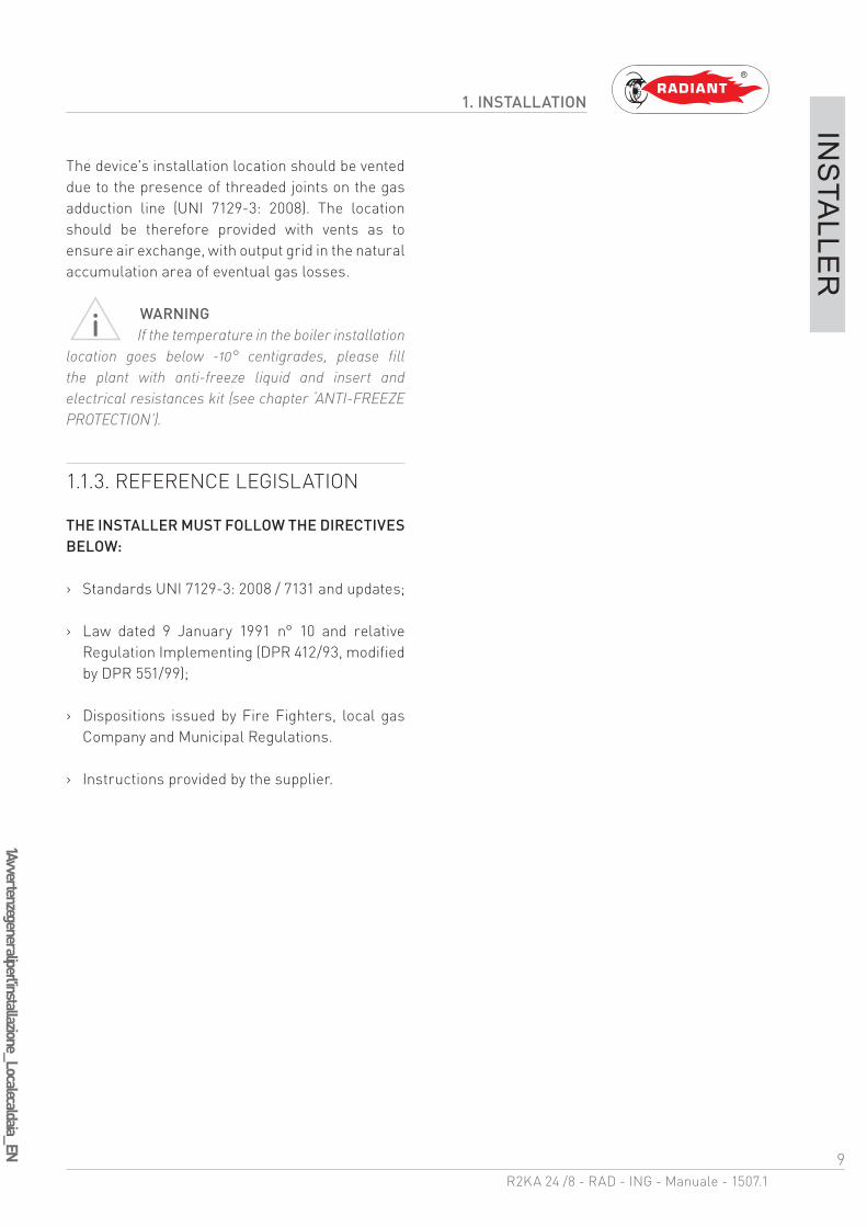
1.1.5. OVERALL DIMENSIONS
1.1.6. JIG
12013819564
150265
785
450350
R C F AG
60 78 70 80 102 60
125
R- RETURN Ø 3/4C - HOT Ø 1/2G- GAS Ø 3/4F- COLD Ø 1/2A - INFEED Ø 3/4

12R2KA 24 /8 - RAD - ING - Manuale - 1507.1
1 Spazi tecnici minim
i e posizionamento_m
urale_v.2_EN
1. INSTALLATION
INS
TALLE
R
1.1.7. POSITIONING AND MINIMAL TECHNICAL SPACES
The boiler must be installed only on a vertical solid wall, able to sustain its weight.
In order to allow the access inside the boiler for maintenance operations, you have to respect the minimum technical spaces indicated in figure 1.
To facilitate the installation, the boiler is provided with a jig that allows setting in advance the connections to the tubes offering you the possibility of connecting the boiler to completed masonry works.
For machine positioning, proceed as follows (see fig. 2):
1. Trace a line using a spirit level (min. length 25 cm) on the installation wall.
2. place the top of the jig along the traced line respecting the distances of the water connections; then mark the two points to insert the two knobs or the fasteners, then trace the points for the fume exhaust fittings;
3. remove the jig and drill the wall;
4. hang the device using the knobs or the bracket and perform the connections.
31 42
70 80 10249 3178
Ø80Ø125
Ø100
35826 26
54 54
821
681 699
302
785
H
B
A
YX
A - 200 mmB - 300 mmX - 60 mm
Y - 60 mmH - 1000 mm
fig.1
fig.2

13R2KA 24 /8 - RAD - ING - Manuale - 1507.1
1 Diagramm
a portata-prevalenza circolatore_R2K 24_v.3_EN
1. INSTALLATION
INS
TALLE
R
WARNINGMake sure, using a level, that the boiler
is properly inclined being levelled (see fig.1) so as to allow the condense to drain.
1.1.8. CIRCULATOR PREVALENCE/FLOW DIAGRAM
III Circulator priority maximum speed
Appliance Loss
fig.1
6
0
1
2
3
4
5
0 0.5 1 1.5 2 2.5
MSL 12/6 COMPACT
III
Wilo-Yonos PARA MSL 12/7.0
0 0,4 0,8 1,2 1,6 2,0 2,4
0 0,1 0,2 0,3 0,4 0,5 0,6 0,7
0 2 4 6 8
0
1
2
3
4
5
6
7
8
0
10
20
30
40
50
70
60
80
0 0,4 0,8 1,2 1,6 2,0 2,40
10
20
30
40
4180/ 15PWM1
4640/ 5PWM1
3210/ 35PWM1
2730/ 45PWM1
2250/ 55PWM1
1280/ 75PWM1
1760/ 65PWM1
800/ 85PWM1
p/kPaH/m
P1/W
Q/m³/ h
Q/l/s
Q/Igpm
Q/m³/ h
max.
max.
3700/ 25PWM1
PR
EVA
LE
NC
E (m
)
FLOW RATE (m3/h)
6
0
1
2
3
4
5
0 0.5 1 1.5 2 2.5

14R2KA 24 /8 - RAD - ING - Manuale - 1507.1
1 Allacciam
ento idraulico_com
binata_EN
1. INSTALLATION
INS
TALLE
R
1.1.9. HYDRAULIC CONNECTION
DANGERMake sure that the tubes of the water and
heating plant are not used as grounding system for the electrical plant. There are not suitable for such use.
WARNINGTo prevent voiding the warranty and to
ensure the proper operation of the boiler, please wash the plant (if possible when hot) with suitable pickling or descaling solutions in order to remove the impurities coming from tubes and radiators.
WARNINGIf the boiler is installed in a hydrostatic
position lower than those of the user devices (radiators, fan coils, etc.), mount the shut-off valves on the domestic water heating circuit to ease the performance of the maintenance operations if it is necessary only to empty the boiler.
WARNINGWhen connecting the equipment to
water supply, avoid excessive bending and recovery operations from any off axis positioning that may damage the tubes causing leaks, malfunction or early wear.
WARNINGIn order to avoid any vibrations and noises,
do not use tubes with small diameters or elbows with small radius and significant cut-off of the passage sections.
DOMESTIC CIRCUIT
In order to prevent limestone build-up and damages to the domestic water heat exchanger, the hardness of the domestic supply water should not exceed 15 °f. However, please check the characteristics of the water used and install suitable treating devices.
The pressure of the cold infeed water should be between 0.5 and 6 bar.
In case of greater pressure values, please install a pressure reducer upstream from the boiler.
The heat exchanger coil cleaning frequency depends on the hardness of the supply water and on the presence of solid residues or impurities inside the water that are often present in case of recently installed plants. Based on the characteristics of the infeed water, you should install suitable water treating devices, for residues presence please install a line filter.
HEATING CIRCUIT
In order to avoid any scale or deposits on the primary exchanger, the heating circuit infeed water should be treated in accordance with the legislation in force.
This treatment is mandatory if frequent episodes of return water or partial or total emptying of the plant occur.
Connect the boiler safety drains (heating circuit safety valve) to a discharge funnel. The manufacturer is not responsible for any floods due to safety valve opening in case of plant overpressure.

15R2KA 24 /8 - RAD - ING - Manuale - 1507.1
1 Ricircolo_
boiler_R
2KA
.8_EN
1. INSTALLATION
INS
TALLE
R
1.1.10. D.H.W. CIRCULATING LOOP
In order to joint the D.H.W out loop pipe, proceed as follows:
› unscrew the ½” cap A (fig.1);
› insert a ½” nipple;
› joint the nipple to the D.H.W. circulating pipe.
KEYRC- D.H.W. CIRCULATING LOOPVR- NO-RETURN VALVEC- CIRCULATORU- TAPSF- COLD WATER MAINS
A
RC
F
C
U
VR
fig. 1

16R2KA 24 /8 - RAD - ING - Manuale - 1507.1
1 Riempim
ento dell'impianto_M
IAH4_R2K
A_.8_EN
1. INSTALLATION
INS
TALLE
R
1.1.11. SYSTEM FILLING
WARNINGFor system filling use only clean tap water.
WARNINGIf the system is filled by adding ethylene
glycol-type chemical agents you have to install on the loading system a hydraulic trip unit in order to separate the heating circuit from the domestic circuit.
Before powering up the boiler, fill the system as follows:
1. Make sure the circulator is not blocked;
2. slightly loosen the cap of the circulator jolly valve (1-fig. 1) to release the air from the system;
3. slightly loosen the cap of the jolly valve placed on the top of the condensing block (fig. 3) to release the air form the top of the system;
4. open the feeding tap “R” (fig. 2);
5. release all the air;
6. use pressure gauge “M” (fig. 2) to make sure that the system pressure reaches 1.2 bar (fig. 4);
7. after performing this operation, make sure that the loading tap “R” (fig. 2) is properly closed.
2
1
M
R
fig. 1
fig. 2
fig. 3

17R2KA 24 /8 - RAD - ING - Manuale - 1507.1
1 Riempim
ento dell'impianto_M
IAH4_R2K
A_.8_EN
1. INSTALLATION
INS
TALLE
R
8. unscrew the circulator cap (2-fig.1) to release any air bubbles and close it to prevent water leakage;
9. open the air relief valves of the radiators and check the air removal process. When the water starts to leak close the radiators air relief valves.
10. if after performing these operations you observe a decrease of the water pressure inside the system, open once again the loading tap “R” until the pressure gauge indicates the value of 1.2 bar (fig. 4)
1.1.12. FILLING THE CONDENSATE COLLECTION SIPHON
Before starting the boiler you have to fill the condensate collection siphon in order to avoid fuel reflux through the siphon.
Fill the condensate collection siphon as follows (see fig. 5):
› Unscrew the “T” cap from the siphon, fill three quarters of the the siphon with water and screw the “T” cap back in;
› Connect the dedicated flexible condensate draining tube “P” (UNI EN 677) to a waste disposal system. The condensate can be drained directly in the sewerage system by inserting an easily serviceable siphon.
P
T
fig. 4
fig. 5

18R2KA 24 /8 - RAD - ING - Manuale - 1507.1
1 Protezione antigelo_
EN
1. INSTALLATION
INS
TALLE
R
1.1.13. ANTI-FREEZE PROTECTION
The boiler is protected against freezing thanks to the electronic board preparation with functions that start the burner and heat the concerned parts when their temperature goes below the minimum pre-set values, protecting the boiler up to an external temperature of -10 °C.
The device starts when the hot water temperature goes below 5 °C, automatically starting the burner until the water reaches the temperature of 30 °C.
The system starts even if on the display appears “OFF”, as long as the boiler is connected to the power (230 V) and gas supply.
For long periods of standby, please empty the boiler and the plant.
If the temperature goes below -10° centigrades, please fill the plant with anti-freeze liquid (CLEANPASS FLUIDO AG cod. 98716LA) and insert and electrical resistances kit (cod. 82259LP).
19R2KA 24 /8 - RAD - ING - Manuale - 1507.1
1 Allacciam
ento gas_elettrico_
MIA
H4_
EN
1. INSTALLATION
INS
TALLE
R
1.1.14. GAS CONNECTION
DANGERIn order to connect the gas connector of
the boiler to the supply pipe use a stop seal of an appropriate size and material. The use of hemp, teflon tape or similar materials is strictly forbidden.
BEFORE PERFORMING THE GAS CONNECTION, MAKE SURE THAT:
› the gas adduction line complies with the standards and regulations in force (UNI-CIG 7129/01 – D.M. 12.04.1996);
› the tubing's section suits the requested capacity and its length;
› the tubing is equipped with all safety and control devices required by the standards in force;
› the internal and external seals of the gas infeed plant are checked;
› the device is suitable for use with the type of gas available by checking the boiler data plate (placed on the inner side of the front casing. If they do not match you must take the necessary measures to adapt the boiler to another type of gas (see chapter GAS TRANSFORMATION);
› the gas supply pressure falls within the values indicated on the data plate.
1.1.15. ELECTRICAL CONNECTION
DANGERThe equipment is electrically safe only
if it is properly connected to an efficient grounding system, performed in compliance with the safety standards in force (STANDARDS CEI 64-8 and 64-9 Electrical Section). You should check this essential safety requirement. If in doubt, request an accurate check of the electrical system performed by qualified staff, as the manufacturer is not responsible for any damages caused by lack of grounding system.
› Make sure that the electrical systems is suitable for the maximum power absorbed by the equipment, value indicated on the data plate.
› make sure that the cables section is appropriate for the maximum power absorbed by the equipment and that it is however not lower than 1 mm2.
› The equipment works with alternating current of 230 V and 50 Hz. The electrical connection must be performed using an all-pole switch with an opening of at least 3 millimetres between contacts placed upstream from the device.
WARNINGMake sure that the phase and neutral
cables connection is performed in compliance with the wiring diagram (see chapter POWER SUPPLY).
WARNINGIt is strictly forbidden the use of adaptors,
multiple plugs and/or extensions for the general power supply of the equipment from the electrical network.

20R2KA 24 /8 - RAD - ING - Manuale - 1507.1
1 Alim
entazione elettrica_EN
1. INSTALLATION
INS
TALLE
R
1.1.16. POWER SUPPLY
To power the boiler connect the electrical cables to the terminal inside the control panel as follows:
DANGERCut off the voltage from the main switch.
› remove the boiler's front casing (refer to chapter ACCESSING THE BOILER).
› loosen the two screws and remove the plate “A” (see fig. 1).
› after removing the plate, connect the electrical cables to terminal “B” (see fig. 1):
· the yellow/green cable to the terminal marked with grounding symbol “ ”.
· the blue cable to the terminal marked with “N”.
· the brown cable to the terminal marked with “L”.
After performing these operations, remount plate “A” and the front casing.
LN
SeSe
A
TaTa
B
BLUEYELLOW/GREEN
BROWN
fig. 1

21R2KA 24 /8 - RAD - ING - Manuale - 1507.1
1 Collegamenti elettrici opzionali_SE_TA_CR_M
IAH4_EN
1. INSTALLATION
INS
TALLE
R
1.1.17. OPTIONAL ELECTRICAL CONNECTIONS
To wire the optionals below:
(SE) EXTERNAL TEMPERATURE PROBE COD. 73518LA
(TA) ENVIRONMENT THERMOSTAT
(CR) REMOTE CONTROL OPEN THERM COD. 40-00017
use the terminal placed inside the control panel as follows:
DANGERCut off the voltage from the main switch.
› remove the front casing of the boiler (see chapter ACCESSING THE BOILER); unscrew the screws and remove plate “A” (see fig. 1).
› After removing the plate, connect the electrical cables to terminal “B” (see fig. 1):
· For the external temperature Probe connect the two non-polarized conductors to the Se-Se contacts.
· For the environment Thermostat or Remote control, first remove the bridge on the Ta-Ta contacts and then connect the two non-polarized conductors to the Ta-Ta contacts.
After performing these operations, remount plate “A” and the front casing.
NB: In case of simultaneous presence of external probe and
remote control, the modulation board only sends the external
temperature value to the remote device without using it for
modulation.
The communication between board and remote control takes
place independently from the boiler's operating mode and after
establishing the connection, the used interface on the board is
disabled and the display shows the symbol ‘ ’.
LN
SeSe
A
TaTa
B
SE
TA
CR
fig. 1

22R2KA 24 /8 - RAD - ING - Manuale - 1507.1
1 Collegam
enti elettrici opzionali_M
IAH
4_EN
1. INSTALLATION
INS
TALLE
R
To wire the optionals below:
use the electronic board placed inside the control panel as follows:
Cut off the voltage from the main switch.
› remove the boiler's front casing (refer to chapter ACCESSING THE BOILER).
› remove the crankcase of the control panel (see chapter ACCESSING THE ELECTRONIC BOARD).
› after removing the crankcase, connect the items below to the electronic board (see fig. 1):
After performing these operations, remount the crankcase and the front casing.
TP
CT
BUS 0-10V
GNDBUS+
1110987
12
13
1415
1617
M12 M9 M7 M5
M2
M4M8
M10
M15
M16
1
2
3
4
57
61605958
44 43 42 41 40 39 38 37 36 35 34 33 32 31 30 29 28 27 26
MIAH4
cema
PM
SR62636465666768
515253545556
5 6
M13
M14
arar
nene
cema
220 V - 50 Hz
L
N
VZR VZ2 VZ1
FC FC
TAZ 2 TAZ 1
SRBN
1
2
3
4
5
69 8 7
M1
M4M2
M3
SVZ
L
gr
ar
ro ne
COD.40-00133
fig. 1
SR: RETURN PROBE FC: AREA VALVES LIMIT SWITCH
SRB: REMOTE LED FOR SIGNALLING BOILER BLOCK GR: GREY
TAZ1: ENVIRONMENT THERMOSTAT AREA 1 AR: ORANGE
TAZ 2: ENVIRONMENT THERMOSTAT AREA 2 NE: BLACK
VZ1: AREA 1 VALVE MA: BROWN
VZ2: AREA 2 VALVE CE: LIGHT BLUE
VZR: REMOTE CONTROLLED AREA VALVE RO: RED

23R2KA 24 /8 - RAD - ING - Manuale - 1507.1
1 Raccordi fum
ari_cond_
EN
1. INSTALLATION
INS
TALLE
R
1.1.18. FUME EXHAUST FITTINGS
WARNINGIn order to ensure proper operation and
efficiency of the device you have to connect the boiler fume exhaust fitting to the fume exhaust duct using appropriate polypropylene flue fittings for condensing boilers. It is recommended to install discharge systems approved by Radiant.
WARNINGYou cannot use traditional flue fittings for
the discharge ducts of the condensing boilers, nor vice versa.
WARNINGFor fumes exhaust and condensate
collection, please follow standard UNI 11071.
› For all discharge ducts, with regard to the fumes path, you should provide an uphill slope (outwards) so as to favour the reflux of the condensate towards the combustion chamber, suitably realized to collect and drain acid condensate.
› For all air suction ducts, with regard to the air path, you should provide an uphill slope (towards the boiler) so as to avoid the protrusion inside the duct of rain water, dust or foreign objects.
› If a vertical fumes duct is installed, insert a condensate collection siphon at the base of the duct connected to the sewerage system of the location (fig. 1).
› In case of horizontal co-axial system installation, correctly place the horizontal co-axial terminal suitably realized to respect the slopes inside the fumes duct and to protect the air suction duct from adverse weather conditions.
› In order to discharge the fumes through a fumes exhaust duct carefully follow the technical standards in force (for example UNI 10641 and UNI EN 13384).
› Make sure that the discharge tube doe not protrude inside the fumes exhaust duct, stop before it reaches the inner surface of the latter.
› The discharge duct must be perpendicular with the opposite internal wall of the chimney or of the fumes exhaust duct (fig. 2).
fig. 1
fig. 2
24R2KA 24 /8 - RAD - ING - Manuale - 1507.1
1 Tipologie di installazione_B23P, B33, C13, C33, C43, C53, C63, C83 e C93_EN
1. INSTALLATION
INS
TALLE
R
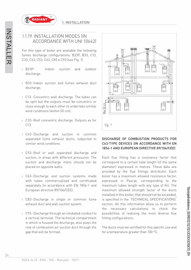
1.1.19. INSTALLATION MODES (IN ACCORDANCE WITH UNI 10642)
For this type of boiler are available the following fumes discharge configurations: B23P, B33, C13, C33, C43, C53, C63, C83 e C93 (see Fig. 1).
› B23P- Indoor suction and outdoor discharge.
› B33- Indoor suction and fumes exhaust duct discharge.
› C13- Concentric wall discharge. The tubes can be split but the outputs must be concentric or close enough to each other to undertake similar wind conditions (within 50 cm).
› C33- Roof concentric discharge. Outputs as for C13.
› C43- Discharge and suction in common separated fume exhaust ducts, subjected to similar wind conditions.
› C53- Roof or wall separated discharge and suction, in areas with different pressures. The suction and discharge inlets should not be placed on opposite walls.
› C63- Discharge and suction systems made with tubes commercialized and certificated separately (in accordance with EN 1856-1 and European directive 89/106/CEE).
› C83- Discharge in single or common fume exhaust duct and wall suction system.
› C93- Discharge through an intubated conduct to a vertical terminal. The technical compartment in which is housed the discharge, also plays the role of combustion air suction duct through the gap that will be formed.
DISCHARGE OF COMBUSTION PRODUCTS FOR C63-TYPE DEVICES (IN ACCORDANCE WITH EN 1856-1 AND EUROPEAN DIRECTIVE 89/106/CEE)
Each flue fitting has a resistance factor that correspond to a certain tube length (of the same diameter) expressed in metres. These data are provided by the flue fittings distributor. Each boiler has a maximum allowed resistance factor, expressed in Pascal, corresponding to the maximum tubes length with any type of Kit. The maximum allowed strength factor of the ducts installed in this boiler, that should not be exceeded, is specified in the ‘TECHNICAL SPECIFICATIONS’ section. All this information allow us to perform the necessary calculations to check the possibilities of realizing the most diverse flue fitting configurations.
The ducts must be certified for this specific use and for a temperature greater than 100 °C.
B23P
C53C13 C13
C43 C43 C83
C33 C33C53
Max
50 cm
B33C93
fig. 1

25R2KA 24 /8 - RAD - ING - Manuale - 1507.1
1 Tipologie di installazione_B23P, B33, C13, C33, C43, C53, C63, C83 e C93_EN
1. INSTALLATION
INS
TALLE
R
DISCHARGE OF COMBUSTION PRODUCTS FOR B-TYPE DEVICES (IN ACCORDANCE WITH UNI 7129)
The gas devices, provided with connection for fumes exhaust tube, must be directly connected to efficient chimneys or fume exhaust ducts: only if these are missing you can discharge the combustion products directly through the gas devices.
The connection to the chimney or to the fume exhaust ducts must respect the following requirements:
· Be sealed and realised in materials suitable to resist normal mechanical stress, heat, the action of combustion products and any condensate forming;
· have no more than three changes in direction, including the chimney and/or fume exhaust duct inlet connection, made with internal angles greater than 90°. The changes in direction must be made only by using curved curved elements;
· have the axis of the inlet end perpendicular to the internal wall opposite to the chimney or fume exhaust duct;
· have, along its entire length, a section equal to or greater then that of the connection of the device discharge tube;
· have no shut-off devices (shutters).
· for direct external discharge there must be no more than two changes in direction.
LOCATIONS VENTING FOR B-TYPE DEVICES (IN ACCORDANCE WITH UNI 7129)
The locations in which are installed gas devices must be vented so as to ensure the amount of air necessary for a regular combustion and for
location ventilation. The natural air intake must take place directly through:
· permanent openings on the external walls of the location (windows);
· single or collective, ramified ventilation ducts.
The openings on the external walls of the location must respect the following requirements:
· have a net overall free passage section of at least 6 cm2 for every kW of heat capacity installed with a minimum of 100 cm2;
· they must be realized so as to make sure that the opening inlets are not obstructed (neither indoors nor outdoors);
· they must be protected with grids, metal meshes, etc. so as to keep the useful section mentioned above.
· they must be placed at a height next to the floor level such as to allow proper operation of the combustion products discharge systems; if such position can not be obtained, please increase by at least 50% the section of the vents.

26R2KA 24 /8 - RAD - ING - Manuale - 1507.1
1 Tipologia di scarico_K
_EN
1. INSTALLATION
INS
TALLE
R
1.1.20. TYPES OF FUME EXHAUST SYSTEMS
KIT K - HORIZONTAL CO-AXIAL SYSTEM Ø60/100 INTERNAL POLYPROPYLENE DUCT ADJUSTABLE AT 360°.
It allows fumes discharge and air intake from external wall.
Suitable only for condensing boilers.
It allows fuel gas discharge and air intake for combustion through co-axial ducts, the external one for air intake, the plastic internal one for fumes discharge.
PLEASE SEE THE MAXIMUM DISCHARGE LENGTH IN THE TABLE IN CHAPTER “TECHNICAL DATA”.
The maximum discharge length (or linear reference length) can be calculated summing the length of the linear tube and that equivalent to each additional curve with respect to the first.
Subsequent addition of a curve is similar to adding a linear length of tube according to the indications below:
co-axial curve Ø60/100 at 90° = 1 m
co-axial curve Ø60/100 at 45° = 0.6 m
Ø10
0
Ø60
100
27R2KA 24 /8 - RAD - ING - Manuale - 1507.1
1 Tipologia di scarico_H
_EN
1. INSTALLATION
INS
TALLE
R
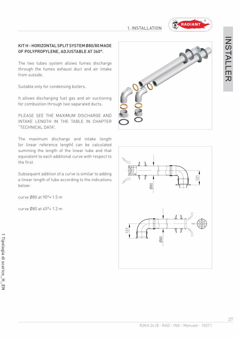
KIT H - HORIZONTAL SPLIT SYSTEM Ø80/80 MADE OF POLYPROPYLENE, ADJUSTABLE AT 360°.
The two tubes system allows fumes discharge through the fumes exhaust duct and air intake from outside.
Suitable only for condensing boilers.
It allows discharging fuel gas and air suctioning for combustion through two separated ducts.
PLEASE SEE THE MAXIMUM DISCHARGE AND INTAKE LENGTH IN THE TABLE IN CHAPTER “TECHNICAL DATA”.
The maximum discharge and intake length (or linear reference length) can be calculated summing the length of the linear tube and that equivalent to each additional curve with respect to the first.
Subsequent addition of a curve is similar to adding a linear length of tube according to the indications below:
curve Ø80 at 90°= 1.5 m
curve Ø80 at 45°= 1.2 m
Ø80
Ø80
121
121

28R2KA 24 /8 - RAD - ING - Manuale - 1507.1
1 Tipologia di scarico_V_EN
1. INSTALLATION
INS
TALLE
R
KIT K - VERTICAL CO-AXIAL SYSTEM Ø60/100 INTERNAL POLYPROPYLENE DUCT.
It allows fumes discharge and air intake directly from roof.
Suitable only for condensing boilers.
It allows fuel gas discharge and air intake for combustion through co-axial ducts, the external one for air intake, the plastic internal one for fumes discharge.
PLEASE SEE THE MAXIMUM DISCHARGE LENGTH IN THE TABLE IN CHAPTER “TECHNICAL DATA”.
The maximum discharge length (or linear reference length) can be calculated summing the length of the linear tube and that equivalent to each additional curve with respect to the first.
Subsequent addition of a curve is similar to adding a linear length of tube according to the indications below:
curve Ø60/100 at 90° = 1 m
curve Ø60/100 at 45° = 0.6 m
Ø100
Ø 60
All operations described below relative to first start-up,
maintenance and replacement should be performed only by
qualified personnel in compliance with art. 3 of D.M. n°37
dated 22.01.2008 and authorized by RADIANT BRUCIATORI
spa.
2. SUPPORT CENTRE SECTION
30R2KA 24 /8 - RAD - ING - Manuale - 1507.1
2 Operazioni prelim
inari per la prima acc_
EN
2. FIRST START-UP
SU
PP
OR
T CE
NTR
E
2.1. FIRST START-UP
2.1.1. PRELIMINARY OPERATIONS FOR FIRST START-UP
The first start-up operations consist in checking the correct installation, adjustment and operation of the device. Proceed as follows:
› check the inner system sealing in accordance with the indications provided by standard UNI 11137-1;
› check if the gas used is suitable for the boiler;
› check if the gas capacity and relative pressures comply with those on the plate;
› check the intervention of the safety device in case of lack of gas;
› make sure that the device supply voltage corresponds with that on the plate (230 V – 50 Hz) and that the wiring is correct;
› make sure that the grounding system works properly;
› make sure that the combustion air adduction and fumes and condensate discharge take place properly in compliance with the Local and National Laws and Standards in force;
› make sure that the fumes discharge tube and its connection to the fume exhaust duct comply with the requirements of the Local and National Laws and Standards;
› make sure that the heating system gate valves are open;
› make sure that there is no intake of gaseous products within the system;
› make sure that there are no flammable liquids or materials near the device;
› open the boiler gas tap and make sure that there are no gas leaks upstream from the device (the burner gas connection must be checked while the machine is running);
› in case of new installation of the gas supply network, the air inside the tubes may block the device at its first start-up. You might have to repeat the start-up procedure to purge all the air inside the tube.

31R2KA 24 /8 - RAD - ING - Manuale - 1507.1
2 Messa in funzione della caldaia_
MIA
H4_
EN
2. FIRST START-UP
SU
PP
OR
T CE
NTR
E
2.1.2. BOILER COMMISSIONING
WARNINGMake sure that the system is correctly
filled.
Proceed with boiler commissioning as follows:
› Power the boiler.
THE START-UP SYSTEM WILL AUTOMATICALLY ACTIVATE THE SYSTEM AIR RELIEF CYCLE FUNCTION DISPLAYED ON SCREEN WITH CODE “F33” (ONLY AT FIRST START-UP WILL LAST FOR 5 MINUTES). When function “F33” is active, the pump is enabled and the burner start-up request is disabled. The boiler can work normally only after completing the operation.
NB.: Only at the first start-up the system relief cycle performed by the boiler lasts 5 minutes. After each water pressure reset the boiler will automatically perform a reduces system relief cycle, of 2 minutes. Throughout this function the display will show the code “F33”. The boiler can work normally only after completing the operation.
› Open the gas tap.
› Use the button ‘ ’ to select the desired operation mode. If the symbol is displayed fixed, it means that the function was activated.
› The burner will start as soon as the thermostat contact is closed;
› if the flame is missing the board will repeat the start-up operations after post-ventilation (20 seconds).
› You might have to repeat the start-up operation several times to release all air inside the gas tube. Before repeating the operation, wait at least 5 seconds from the last start-up attempt and unlock the boiler from “E01” error code by pressing the Reset ‘ ’ key.
32R2KA 24 /8 - RAD - ING - Manuale - 1507.1
2 Verifica e taratura del valore di CO2_MIAH4_R2KA_.8_EN
2. FIRST START-UP
SU
PP
OR
T CE
NTR
E
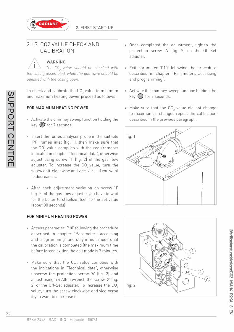
2.1.3. CO2 VALUE CHECK AND CALIBRATION
WARNINGThe CO2 value should be checked with
the casing assembled, while the gas valve should be adjusted with the casing open.
To check and calibrate the CO2 value to minimum and maximum heating power proceed as follows:
FOR MAXIMUM HEATING POWER
› Activate the chimney sweep function holding the key ‘ ’ for 7 seconds.
› Insert the fumes analyser probe in the suitable ‘PF’ fumes inlet (fig. 1), then make sure that the CO2 value complies with the requirements indicated in chapter “Technical data”, otherwise adjust using screw ‘1’ (fig. 2) of the gas flow adjuster. To increase the CO2 value, turn the screw anti-clockwise and vice-versa if you want to decrease it.
› After each adjustment variation on screw ‘1’ (fig. 2) of the gas flow adjuster you have to wait for the boiler to stabilize itself to the set value (about 30 seconds).
FOR MINIMUM HEATING POWER
› Access parameter ‘P10’ following the procedure described in chapter “Parameters accessing and programming” and stay in edit mode until the calibration is completed (the maximum time before forced exiting the edit mode is 7 minutes.
› Make sure that the CO2 value complies with the indications in “Technical data”, otherwise unscrew the protection screw ‘A’ (fig. 2) and adjust using a 4 Allen wrench the screw ‘2’ (fig. 2) of the Off-Set adjuster. To increase the CO2
value, turn the screw clockwise and vice-versa if you want to decrease it.
› Once completed the adjustment, tighten the protection screw ‘A’ (fig. 2) on the Off-Set adjuster.
› Exit parameter ‘P10’ following the procedure described in chapter “Parameters accessing and programming”.
› Activate the chimney sweep function holding the key ‘ ’ for 7 seconds.
› Make sure that the CO2 value did not change to maximum, if changed repeat the calibration described in the previous paragraph.
PF
1
2
A
fig. 1
fig. 2

33R2KA 24 /8 - RAD - ING - Manuale - 1507.1
2 Accesso e programm
azione dei parametri_M
IAH4_R2_GRIGIO_EN
2. FIRST START-UP
SU
PP
OR
T CE
NTR
E
2.1.4. ACCESSING AND PROGRAMMING THE PARAMETERS
To access the parameters menu and adjust their values, follow the procedure below:
1. Press the button ‘ ’ to select the OFF mode displayed using the symbol ‘ ’.
2. Hold at the same time the keys ‘ ’ and ‘’ until on the display appears the symbol ‘’with the message ‘P00’, and release the keys ‘ ’ and ‘ ’.
3. Use the keys ‘ ’ and ‘ ’ of the heating circuit to select the parameter to be edited.
34R2KA 24 /8 - RAD - ING - Manuale - 1507.1
2 Accesso e programm
azione dei parametri_M
IAH4_R2_GRIGIO_EN
2. FIRST START-UP
SU
PP
OR
T CE
NTR
E
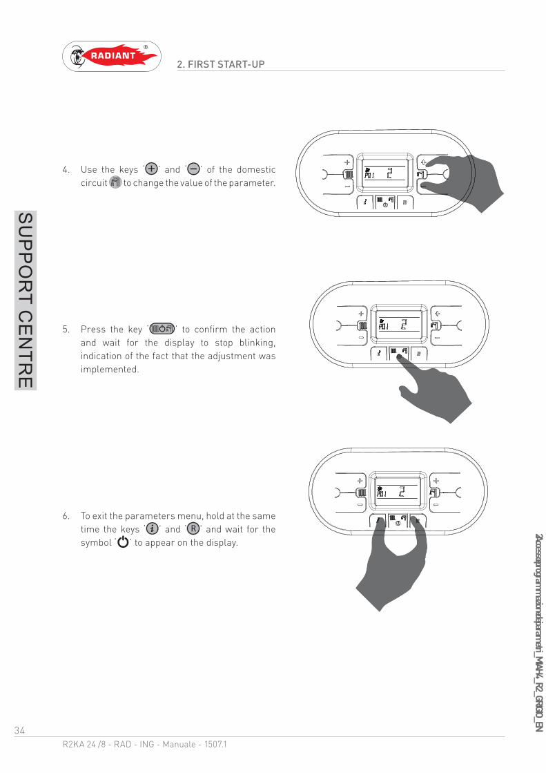
4. Use the keys ‘ ’ and ‘ ’ of the domestic circuit to change the value of the parameter.
5. Press the key ‘ ’ to confirm the action and wait for the display to stop blinking, indication of the fact that the adjustment was implemented.
6. To exit the parameters menu, hold at the same time the keys ‘ ’ and ‘ ’ and wait for the symbol ‘ ’ to appear on the display.
35R2KA 24 /8 - RAD - ING - Manuale - 1507.1
2 Tabella parametri_
MIA
H4_
EN
2. FIRST START-UP
SU
PP
OR
T CE
NTR
E
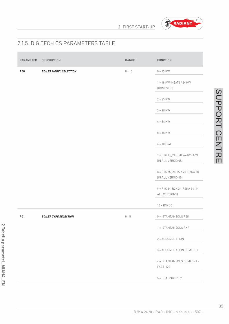
2.1.5. DIGITECH CS PARAMETERS TABLE
PARAMETER DESCRIPTION RANGE FUNCTION
P00 BOILER MODEL SELECTION 0 - 10 0 = 13 KW
1 = 18 KW (HEAT.) / 24 KW
(DOMESTIC)
2 = 25 KW
3 = 28 KW
4 = 34 KW
5 = 55 KW
6 = 100 KW
7 = R1K 18_24-R2K 24-R2KA 24
(IN ALL VERSIONS)
8 = R1K 25_28-R2K 28-R2KA 28
(IN ALL VERSIONS)
9 = R1K 34-R2K 34-R2KA 34 (IN
ALL VERSIONS)
10 = R1K 50
P01 BOILER TYPE SELECTION 0 - 5 0 = ISTANTANEOUS R2K
1 = ISTANTANEOUS RKR
2 = ACCUMULATION
3 = ACCUMULATION COMFORT
4 = ISTANTANEOUS COMFORT -
FAST H2O
5 = HEATING ONLY

36R2KA 24 /8 - RAD - ING - Manuale - 1507.1
2 Tabella parametri_
MIA
H4_
EN
2. FIRST START-UP
SU
PP
OR
T CE
NTR
E
PARAMETER DESCRIPTION RANGE FUNCTION
P02 GAS TYPE SELECTION
ATTENTION:
READ THE INSTRUCTION IN CHAPTER ‘GAS
TRANSFORMATION’ BEFORE CHANGING THIS PARAMETER.
0 - 1 0 = METHANE
1 = GPL
P03 SETTING THE HEATING TEMPERATURE 0 - 1 0 = STANDARD (30-80 °C)
(SET BY DEFAULT)
1 = REDUCED (25-45 °C) FOR
FLOOR SYSTEMS
P04 HEATING RUN-UP
THROUGH THIS PARAMETER YOU CAN SET THE TIME,
DURING START-UP PHASE, NECESSARY FOR THE BOILER
TO REACH THE MAXIMUM SET POWER (ON THE HEATING
SIDE).
0 - 4 0 = (DISABLED)
1 = 50 SECONDS
(SET BY DEFAULT)
2 = 100 SECONDS
3 = 200 SECONDS
4 = 400 SECONDS
P05 ANTI-WATER HAMMER SELECTION
ONCE THIS FUNCTION IS ENABLED, THE DHW CONTACT
WILL BE DELAYED FOR A TIME EQUAL TO THE SET VALUE.
0 - 20 0 = DISABLED
1 - 20 = THE VALUE IS
EXPRESSED IN SECONDS
P06 DOMESTIC CIRCUIT PRESERVATION FUNCTION
(ONLY FOR FAST BOILERS)
THROUGH THIS PARAMETER YOU CAN PRESERVE
THE CIRCULATOR THE DIVERTER VALVE IN DOMESTIC
POSITION FOR A PERIOD OF TIME EQUAL TO THE POST-
CIRCULATION (SEE PARAMETER P08), SO AS TO MAINTAIN
THE SECONDARY EXCHANGER HOT.
0 - 1 0 = DISABLED
(SET BY DEFAULT)
1 = ENABLED
P07 HEATING TIMING
THROUGH THIS PARAMETER YOU CAN SET THE MINIMUM
TIME FOR WHICH THE BURNER WILL BE TURNED OFF
ONCE THE HEATING TEMPERATURE REACHED THE USER
SET TEMPERATURE.
0 - 90 VALUE EXPRESSED IN
MULTIPLES OF 5 SECONDS
(PRE-SET AT 36 X 5 = 180
SECONDS)
37R2KA 24 /8 - RAD - ING - Manuale - 1507.1
2 Tabella parametri_
MIA
H4_
EN
2. FIRST START-UP
SU
PP
OR
T CE
NTR
E
PARAMETER DESCRIPTION RANGE FUNCTION
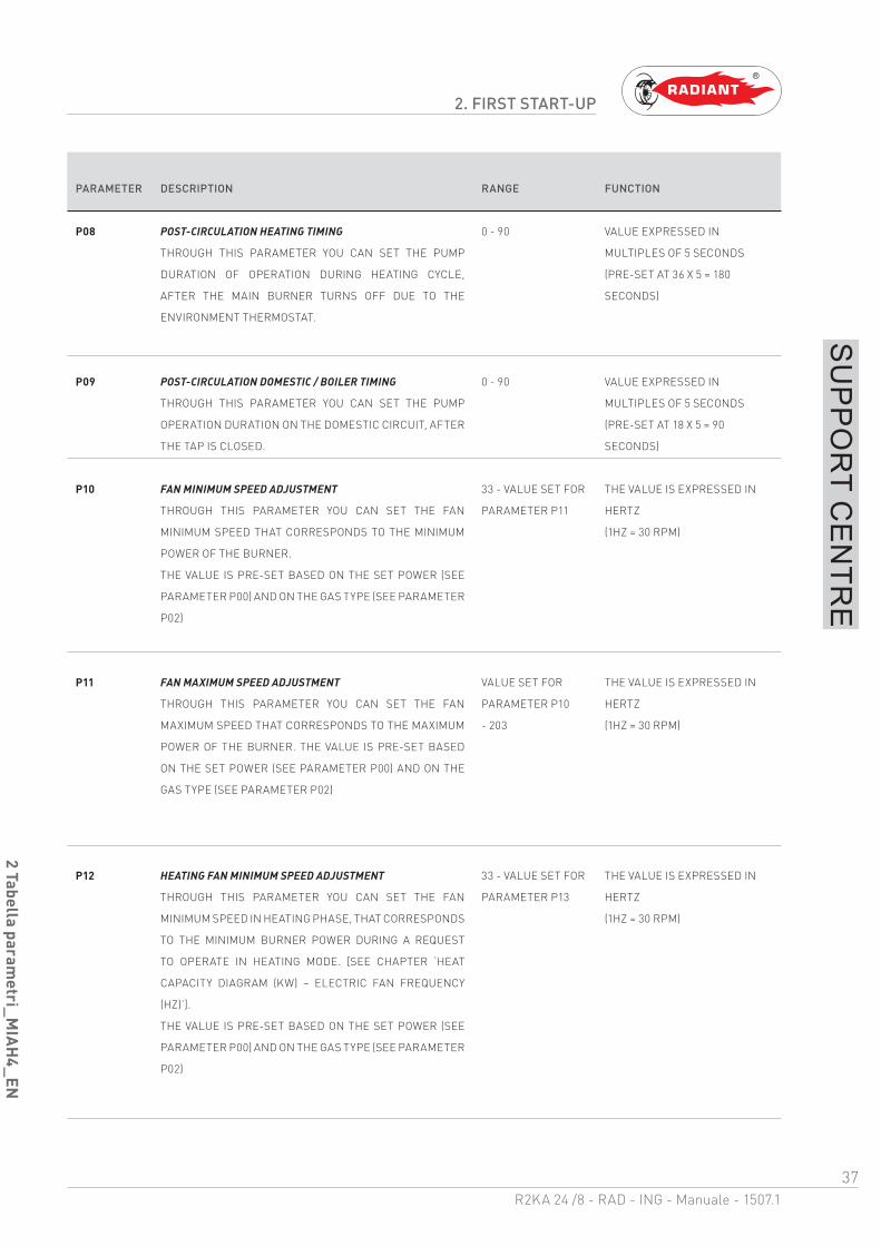
P08 POST-CIRCULATION HEATING TIMING
THROUGH THIS PARAMETER YOU CAN SET THE PUMP
DURATION OF OPERATION DURING HEATING CYCLE,
AFTER THE MAIN BURNER TURNS OFF DUE TO THE
ENVIRONMENT THERMOSTAT.
0 - 90 VALUE EXPRESSED IN
MULTIPLES OF 5 SECONDS
(PRE-SET AT 36 X 5 = 180
SECONDS)
P09 POST-CIRCULATION DOMESTIC / BOILER TIMING
THROUGH THIS PARAMETER YOU CAN SET THE PUMP
OPERATION DURATION ON THE DOMESTIC CIRCUIT, AFTER
THE TAP IS CLOSED.
0 - 90 VALUE EXPRESSED IN
MULTIPLES OF 5 SECONDS
(PRE-SET AT 18 X 5 = 90
SECONDS)
P10 FAN MINIMUM SPEED ADJUSTMENT
THROUGH THIS PARAMETER YOU CAN SET THE FAN
MINIMUM SPEED THAT CORRESPONDS TO THE MINIMUM
POWER OF THE BURNER.
THE VALUE IS PRE-SET BASED ON THE SET POWER (SEE
PARAMETER P00) AND ON THE GAS TYPE (SEE PARAMETER
P02)
33 - VALUE SET FOR
PARAMETER P11
THE VALUE IS EXPRESSED IN
HERTZ
(1HZ = 30 RPM)
P11 FAN MAXIMUM SPEED ADJUSTMENT
THROUGH THIS PARAMETER YOU CAN SET THE FAN
MAXIMUM SPEED THAT CORRESPONDS TO THE MAXIMUM
POWER OF THE BURNER. THE VALUE IS PRE-SET BASED
ON THE SET POWER (SEE PARAMETER P00) AND ON THE
GAS TYPE (SEE PARAMETER P02)
VALUE SET FOR
PARAMETER P10
- 203
THE VALUE IS EXPRESSED IN
HERTZ
(1HZ = 30 RPM)
P12 HEATING FAN MINIMUM SPEED ADJUSTMENT
THROUGH THIS PARAMETER YOU CAN SET THE FAN
MINIMUM SPEED IN HEATING PHASE, THAT CORRESPONDS
TO THE MINIMUM BURNER POWER DURING A REQUEST
TO OPERATE IN HEATING MODE. [SEE CHAPTER ‘HEAT
CAPACITY DIAGRAM (KW) – ELECTRIC FAN FREQUENCY
(HZ)’].
THE VALUE IS PRE-SET BASED ON THE SET POWER (SEE
PARAMETER P00) AND ON THE GAS TYPE (SEE PARAMETER
P02)
33 - VALUE SET FOR
PARAMETER P13
THE VALUE IS EXPRESSED IN
HERTZ
(1HZ = 30 RPM)
38R2KA 24 /8 - RAD - ING - Manuale - 1507.1
2 Tabella parametri_
MIA
H4_
EN
2. FIRST START-UP
SU
PP
OR
T CE
NTR
E
PARAMETER DESCRIPTION RANGE FUNCTION
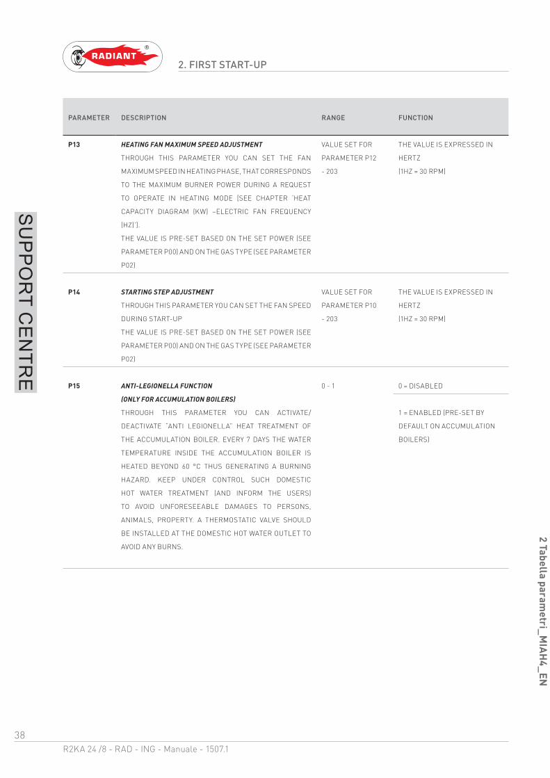
P13 HEATING FAN MAXIMUM SPEED ADJUSTMENT
THROUGH THIS PARAMETER YOU CAN SET THE FAN
MAXIMUM SPEED IN HEATING PHASE, THAT CORRESPONDS
TO THE MAXIMUM BURNER POWER DURING A REQUEST
TO OPERATE IN HEATING MODE [SEE CHAPTER ‘HEAT
CAPACITY DIAGRAM (KW) –ELECTRIC FAN FREQUENCY
(HZ)’].
THE VALUE IS PRE-SET BASED ON THE SET POWER (SEE
PARAMETER P00) AND ON THE GAS TYPE (SEE PARAMETER
P02)
VALUE SET FOR
PARAMETER P12
- 203
THE VALUE IS EXPRESSED IN
HERTZ
(1HZ = 30 RPM)
P14 STARTING STEP ADJUSTMENT
THROUGH THIS PARAMETER YOU CAN SET THE FAN SPEED
DURING START-UP
THE VALUE IS PRE-SET BASED ON THE SET POWER (SEE
PARAMETER P00) AND ON THE GAS TYPE (SEE PARAMETER
P02)
VALUE SET FOR
PARAMETER P10
- 203
THE VALUE IS EXPRESSED IN
HERTZ
(1HZ = 30 RPM)
P15 ANTI-LEGIONELLA FUNCTION
(ONLY FOR ACCUMULATION BOILERS)
THROUGH THIS PARAMETER YOU CAN ACTIVATE/
DEACTIVATE “ANTI LEGIONELLA” HEAT TREATMENT OF
THE ACCUMULATION BOILER. EVERY 7 DAYS THE WATER
TEMPERATURE INSIDE THE ACCUMULATION BOILER IS
HEATED BEYOND 60 °C THUS GENERATING A BURNING
HAZARD. KEEP UNDER CONTROL SUCH DOMESTIC
HOT WATER TREATMENT (AND INFORM THE USERS)
TO AVOID UNFORESEEABLE DAMAGES TO PERSONS,
ANIMALS, PROPERTY. A THERMOSTATIC VALVE SHOULD
BE INSTALLED AT THE DOMESTIC HOT WATER OUTLET TO
AVOID ANY BURNS.
0 - 1 0 = DISABLED
1 = ENABLED (PRE-SET BY
DEFAULT ON ACCUMULATION
BOILERS)

39R2KA 24 /8 - RAD - ING - Manuale - 1507.1
2 Tabella parametri_
MIA
H4_
EN
2. FIRST START-UP
SU
PP
OR
T CE
NTR
E
PARAMETER DESCRIPTION RANGE FUNCTION
P16 CLIMATE COMPENSATION CURVE
(ONLY WITH EXTERNAL PROBE CONNECTED)
YOU CAN CONNECT AN EXTERNAL TEMPERATURE PROBE
(SEE CHAPTER ‘ELECTRICAL CONNECTIONS’) THAT
AUTOMATICALLY CHANGES THE DELIVERY TEMPERATURE
BASED ON THE EXTERNAL MEASURED TEMPERATURE.
THE NATURE OF THE CORRECTION DEPENDS ON THE
THERMO-ADJUSTMENT VALUE KD SET (SEE CHART).
THE SELECTION OF THE CURVE IS DETERMINED BY
THE MAXIMUM DELIVERY TEMPERATURE TM AND THE
MINIMUM EXTERNAL TEMPERATURE TE TAKING INTO
ACCOUNT THE HOUSE INSULATION DEGREE.
THE VALUES OF THE DELIVERY TEMPERATURES TM, REFER
TO STANDARD SYSTEMS 30-80 °C OR FLOOR SYSTEMS 25-
45 °C. THE SYSTEM TYPE CAN BE SET FROM PARAMETER
P03.
0 - 30 (SET BY DEFAULT AT 15) THE
NUMBERING OF THE VALUE
CORRESPONDS TO ‘KD’ CURVES
ON THE CHART (SEE CHART
BELOW).
Te (°C)353025201510
75
8045 MAX
Tm (°C)
50-5-10
65
55
60
50
40
45
35
30
30
-15-20
25 MIN
35
70
Kd = 0
Kd = 5
Kd = 10
Kd = 15Kd = 20 Kd = 25 Kd = 30
40R2KA 24 /8 - RAD - ING - Manuale - 1507.1
2 Tabella parametri_
MIA
H4_
EN
2. FIRST START-UP
SU
PP
OR
T CE
NTR
E
PARAMETER DESCRIPTION RANGE FUNCTION
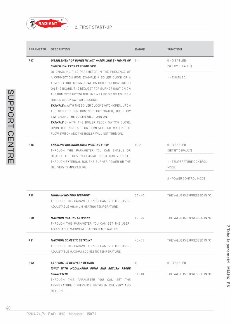
P17 DISABLEMENT OF DOMESTIC HOT WATER LINE BY MEANS OF
SWITCH (ONLY FOR FAST BOILERS)
BY ENABLING THIS PARAMETER IN THE PRESENCE OF
A CONNECTION (FOR EXAMPLE A BOILER CLOCK OR A
TEMPERATURE THERMOSTAT) ON BOILER CLOCK SWITCH
ON THE BOARD, THE REQUEST FOR BURNER IGNITION ON
THE DOMESTIC HOT WATER LINE WILL BE DISABLED UPON
BOILER CLOCK SWITCH CLOSURE.
EXAMPLE 1: WITH THE BOILER CLOCK SWITCH OPEN, UPON
THE REQUEST FOR DOMESTIC HOT WATER, THE FLOW
SWITCH AND THE BOILER WILL TURN ON.
EXAMPLE 2: WITH THE BOILER CLOCK SWITCH CLOSE,
UPON THE REQUEST FOR DOMESTIC HOT WATER, THE
FLOW SWITCH AND THE BOILER WILL NOT TURN ON.
0 - 1 0 = DISABLED
(SET BY DEFAULT)
1 = ENABLED
P18 ENABLING BUS INDUSTRIAL PILOTING 0 -10V
THROUGH THIS PARAMETER YOU CAN ENABLE OR
DISABLE THE BUS INDUSTRIAL INPUT 0-10 V TO SET
THROUGH EXTERNAL BUS THE BURNER POWER OR THE
DELIVERY TEMPERATURE.
0 - 2 0 = DISABLED
(SET BY DEFAULT)
1 = TEMPERATURE CONTROL
MODE
2 = POWER CONTROL MODE
P19 MINIMUM HEATING SETPOINT
THROUGH THIS PARAMETER YOU CAN SET THE USER-
ADJUSTABLE MINIMUM HEATING TEMPERATURE.
20 - 40 THE VALUE IS EXPRESSED IN °C
P20 MAXIMUM HEATING SETPOINT
THROUGH THIS PARAMETER YOU CAN SET THE USER-
ADJUSTABLE MAXIMUM HEATING TEMPERATURE.
40 - 90 THE VALUE IS EXPRESSED IN °C
P21 MAXIMUM DOMESTIC SETPOINT
THROUGH THIS PARAMETER YOU CAN SET THE USER-
ADJUSTABLE MAXIMUM DOMESTIC TEMPERATURE.
45 - 75 THE VALUE IS EXPRESSED IN °C
P22 SET POINT T DELIVERY-RETURN
(ONLY WITH MODULATING PUMP AND RETURN PROBE
CONNECTED)
THROUGH THIS PARAMETER YOU CAN SET THE
TEMPERATURE DIFFERENCE BETWEEN DELIVERY AND
RETURN.
0 0 = DISABLED
10 - 40 THE VALUE IS EXPRESSED IN °C

41R2KA 24 /8 - RAD - ING - Manuale - 1507.1
2 Tabella parametri_
MIA
H4_
EN
2. FIRST START-UP
SU
PP
OR
T CE
NTR
E
PARAMETER DESCRIPTION RANGE FUNCTION
P23 MODULATING PUMP MINIMUM SPEED
(ONLY WITH MODULATING PUMP AND RETURN PROBE
CONNECTED)
THROUGH THIS PARAMETER YOU CAN SET THE MINIMUM
SPEED VALUE OF THE MODULATING PUMP DURING A
REQUEST TO OPERATE IN HEATING MODE.
50 - 70 THE VALUE IS EXPRESSED IN
PERCENTAGE
P24 MODULATING PUMP MAXIMUM SPEED
(ONLY WITH MODULATING PUMP AND RETURN PROBE
CONNECTED)
THROUGH THIS PARAMETER YOU CAN SET THE MAXIMUM
SPEED VALUE OF THE MODULATING PUMP DURING A
REQUEST TO OPERATE IN HEATING MODE.
70 - 100 THE VALUE IS EXPRESSED IN
PERCENTAGE
P25 CONTROL PERIOD T DELIVERY-RETURN
(ONLY WITH MODULATING PUMP AND RETURN PROBE
CONNECTED)
THROUGH THIS PARAMETER YOU CAN SET THE RESPONSE
TIME TO THE PUMP MODULATION.
20 - 100 THE VALUE IS EXPRESSED IN
SECONDS
42R2KA 24 /8 - RAD - ING - Manuale - 1507.1
2 Diagramm
a portata termica - frequenza elettr_R2K 24_EN
2. FIRST START-UP
SU
PP
OR
T CE
NTR
E
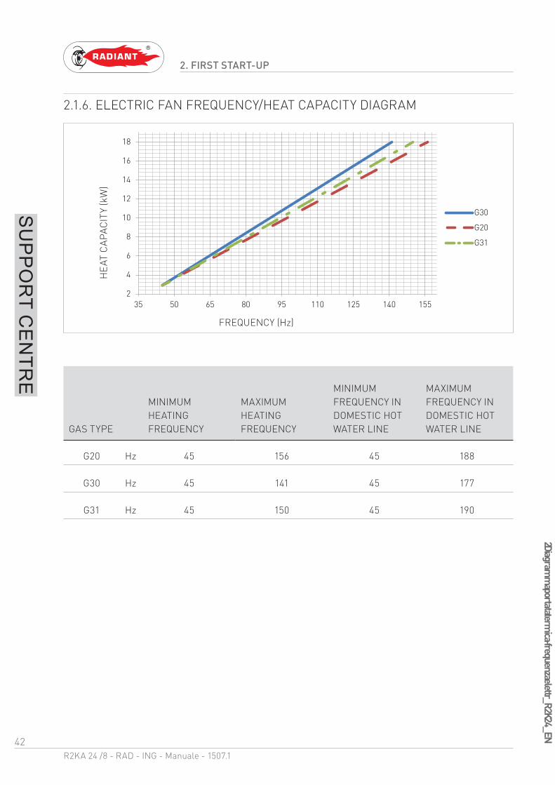
2.1.6. ELECTRIC FAN FREQUENCY/HEAT CAPACITY DIAGRAM
GAS TYPE
MINIMUM HEATING FREQUENCY
MAXIMUM HEATING FREQUENCY
MINIMUM FREQUENCY IN DOMESTIC HOT WATER LINE
MAXIMUM FREQUENCY IN DOMESTIC HOT WATER LINE
G20 Hz 45 156 45 188
G30 Hz 45 141 45 177
G31 Hz 45 150 45 190
2
4
6
8
10
12
14
16
18
35 50 65 80 95 110 125 140 155
G30
G20
G31
HE
AT C
AP
AC
ITY
(kW
)
FREQUENCY (Hz)

43R2KA 24 /8 - RAD - ING - Manuale - 1507.1
2 Avvertenze generali per la manutenzione_conbinata_cond_EN
2. MAINTENANCE
SU
PP
OR
T CE
NTR
E
2.2. MAINTENANCE
2.2.7. GENERAL MAINTENANCE WARNINGS
ATTENTIONAll maintenance operations must be
performed in compliance with standards UNI 7129-3: 2008 and subsequent amendments by qualified staff in accordance with art. 3 of D.M. n°37 dated 22.01.2008. and authorized by RADIANT BRUCIATORI spa.
WARNINGIn accordance with art. 11 of D.P.R. 412/93
and subsequent amendments, the maintenance operations must be performed once every twelve months starting from the boiler installation date.
WARNINGTo ensure greater life span and proper
operation of the device, during the maintenance operations use only original spare parts.
DANGERBefore each components cleaning or
replacement operation, ALWAYS cut off the POWER, WATER and GAS supply of the boiler.
Please perform the following operations once a year:
› check the sealing of the gas components, and replace if necessary the gaskets;
› check the sealing of the water components, and replace if necessary the gaskets;
› visually check the flame and the condition of the combustion chamber;
› if necessary make sure that the combustion is suitably adjusted and if required proceed as indicated in section “CO2 VALUE CHECK AND CALIBRATION”;
› remove and clean the burner from oxidation;
› check the integrity and the position of the sealed chamber sealing gasket;
› check the primary exchanger, if necessary, clean it;
› check the operation of the gas light up and safety systems. If necessary, remove and clean the flame detection and light up electrodes from incrustations paying attention to respect the distances with respect to the burner;
› check the heating circuit safety systems: limit temperature safety thermostat; limit pressure safety;
› check the pre-load pressure of the expansion vessel;
› make sure that the permanent ventilation outlets are present, correctly sized and functioning, based on the installed devices. Respect the requirements provided by Local and National legislation;
› periodically check the integrity of the fume exhaustion system for safety and proper operation;
› check that the wiring is performed in compliance with the requirements in the boiler instruction manual;
› check the wiring inside the control panel;
› check the flow and temperature of domestic hot water;
› check the proper operation of the condensate draining system, including the devices outside the boiler such as condensate collection devices

44R2KA 24 /8 - RAD - ING - Manuale - 1507.1
2 Avvertenze generali per la manutenzione_conbinata_cond_EN
2. MAINTENANCE
SU
PP
OR
T CE
NTR
E
installed along the path of the fume exhaust duct or neutralization devices for acid condensate.
› check that the liquid flow is not obstructed and that there are no combustion gas refluxes inside the internal system.
45R2KA 24 /8 - RAD - ING - Manuale - 1507.1
2 Dati tecnici_
R2K
A 24.8_
EN
2. MAINTENANCE
SU
PP
OR
T CE
NTR
E
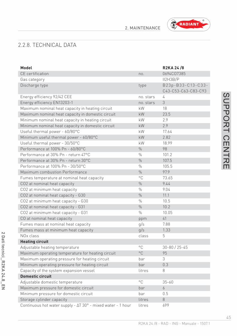
2.2.8. TECHNICAL DATA
Model R2KA 24 /8CE certification no. 0694CO7385Gas category II2H3B/PDischarge type type B2 3p-B 3 3-C13-C 3 3-
C43-C53-C63-C83-C93Energy efficiency 92/42 CEE no. stars 4Energy efficiency EN13203-1 no. stars 3Maximum nominal heat capacity in heating circuit kW 18Maximum nominal heat capacity in domestic circuit kW 23.5Minimum nominal heat capacity in heating circuit kW 2.9Minimum nominal heat capacity in domestic circuit kW 2.9Useful thermal power - 60/80°C kW 17.64Minimum useful thermal power - 60/80°C kW 2.82Useful thermal power - 30/50°C kW 18.99Performance at 100% Pn - 60/80°C % 98Performance at 30% Pn - return 47°C % 101.2Performance at 30% Pn - return 30°C % 107.5Performance at 100% Pn - 30/50°C % 105.5Maximum combustion Performance % 97.9Fumes temperature at nominal heat capacity °C 73.65CO2 at nominal heat capacity % 9.44CO2 at minimum heat capacity % 9.04CO2 at nominal heat capacity - G30 % 11.1CO2 at minimum heat capacity - G30 % 10.5CO2 at nominal heat capacity - G31 % 10.2CO2 at minimum heat capacity - G31 % 10.05CO at nominal heat capacity ppm 41Fumes mass at nominal heat capacity g/s 7.88Fumes mass at minimum heat capacity g/s 1.33NOx class class 5Heating circuitAdjustable heating temperature °C 30-80 / 25-45Maximum operating temperature for heating circuit °C 95Maximum operating pressure for heating circuit bar 3Minimum operating pressure for heating circuit bar 0.3Capacity of the system expansion vessel litres 8Domestic circuitAdjustable domestic temperature °C 35-60Maximum pressure for domestic circuit bar 6Minimum pressure for domestic circuit bar 0.5Storage cylinder capacity litres 8Continuous hot water supply - ΔT 30° - mixed water - 1 hour litres 699
46R2KA 24 /8 - RAD - ING - Manuale - 1507.1
2 Dati tecnici_
R2K
A 24.8_
EN
2. MAINTENANCE
SU
PP
OR
T CE
NTR
E
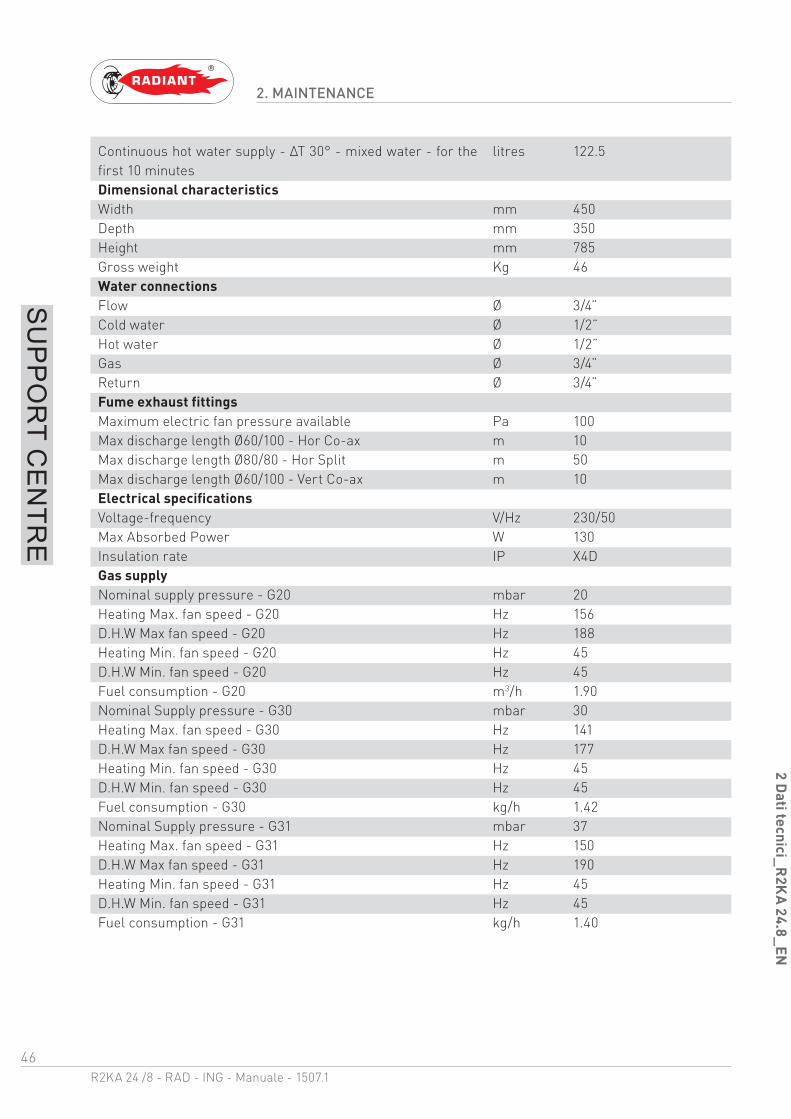
Continuous hot water supply - ΔT 30° - mixed water - for the first 10 minutes
litres 122.5
Dimensional characteristicsWidth mm 450Depth mm 350Height mm 785Gross weight Kg 46Water connectionsFlow Ø 3/4”Cold water Ø 1/2”Hot water Ø 1/2”Gas Ø 3/4”Return Ø 3/4”Fume exhaust fittingsMaximum electric fan pressure available Pa 100Max discharge length Ø60/100 - Hor Co-ax m 10Max discharge length Ø80/80 - Hor Split m 50Max discharge length Ø60/100 - Vert Co-ax m 10Electrical specificationsVoltage-frequency V/Hz 230/50Max Absorbed Power W 130Insulation rate IP X4DGas supplyNominal supply pressure - G20 mbar 20Heating Max. fan speed - G20 Hz 156D.H.W Max fan speed - G20 Hz 188Heating Min. fan speed - G20 Hz 45D.H.W Min. fan speed - G20 Hz 45Fuel consumption - G20 m3/h 1.90Nominal Supply pressure - G30 mbar 30Heating Max. fan speed - G30 Hz 141D.H.W Max fan speed - G30 Hz 177Heating Min. fan speed - G30 Hz 45D.H.W Min. fan speed - G30 Hz 45Fuel consumption - G30 kg/h 1.42Nominal Supply pressure - G31 mbar 37Heating Max. fan speed - G31 Hz 150D.H.W Max fan speed - G31 Hz 190Heating Min. fan speed - G31 Hz 45D.H.W Min. fan speed - G31 Hz 45Fuel consumption - G31 kg/h 1.40

47R2KA 24 /8 - RAD - ING - Manuale - 1507.1
2 Com
plessivo tecnico_R
2KA
_.8_
EN
2. MAINTENANCE
SU
PP
OR
T CE
NTR
E
2.2.9. TECHNICAL ASSEMBLY
KEY1. FUMES SAFETY THERMOFUSE 2. INTEGRATED HEAT EXCHANGER3. BURNER UNIT4. DETECTION ELECTRODE5. ELECTRIC FAN6. CONDENSATE COLLECTION SIPHON7. SAFETY VALVE 3 bar8. AIR RELIEF VALVE9. CIRCULATOR10. SYSTEM DRAINING TAP11. ANODE12. SAFETY VALVE 8 bar13. SAFETY THERMOSTAT14. HEATING PROBE15. LIGHT UP ELECTRODE16. AIR SUCTION TUBE17. DOMESTIC CIRCUIT PROBE18. CYLINDER19. START-UP TRANSFORMER20. PROPORTIONAL VENTURI21. GAS VALVE22. WATER PRESSURE SWITCH
23. DIVERTER VALVE24. FLOW SWITCH25. FLOW LIMITER26. SYSTEM FILLING TAP
1
2
3
4
56
7
10
8
13
15
19
21
20
23
26
11
12
17
22
2425
9
14
16
18
8

48R2KA 24 /8 - RAD - ING - Manuale - 1507.1
2 Schema idraulico_
R2K
A_
.8_EN
2. MAINTENANCE
SU
PP
OR
T CE
NTR
E
2.2.10. HYDRAULIC BOARD
KEYR. HEATING RETURNC. DOMESTIC HOT WATER OUTLETG. GAS INLETSC. CONDENSATE DRAINF. COLD WATER INLETA. HEATING FORWARD
1. FUMES SAFETY THERMOFUSE2. INTEGRATED HEAT EXCHANGER3. BURNER UNIT4. ELECTRIC FAN5. EXPANSION TANK6. CONDENSATE COLLECTION SIPHON7. AIR RELIEF VALVE8. CIRCULATOR9. SAFETY VALVE 3 bar10. SYSTEM DRAINING TAP11. FLOW LIMITER12. HEATING PROBE13. SAFETY THERMOSTAT14. AIR SUCTION TUBE15. PROPORTIONAL VENTURI
16. GAS VALVE17. BY-PASS18. WATER PRESSURE SWITCH19. DIVERTER VALVE20. FLOW SWITCH21. NO-RETURN VALVE22. SYSTEM FILLING TAP23. ANODE24. CYLINDER25. SAFETY VALVE 8 bar26. DOMESTIC CIRCUIT PROBE27. CYLINDER DRAINING TAP
R G FC ASC
2
4
5
7
9
7
14
15
16
2324
25
1
8
10
1213
1819202122
27
26
3
11
6 17
49R2KA 24 /8 - RAD - ING - Manuale - 1507.1
2 Funzionamento valvola dev._
rapida_EN
2. MAINTENANCE
SU
PP
OR
T CE
NTR
E
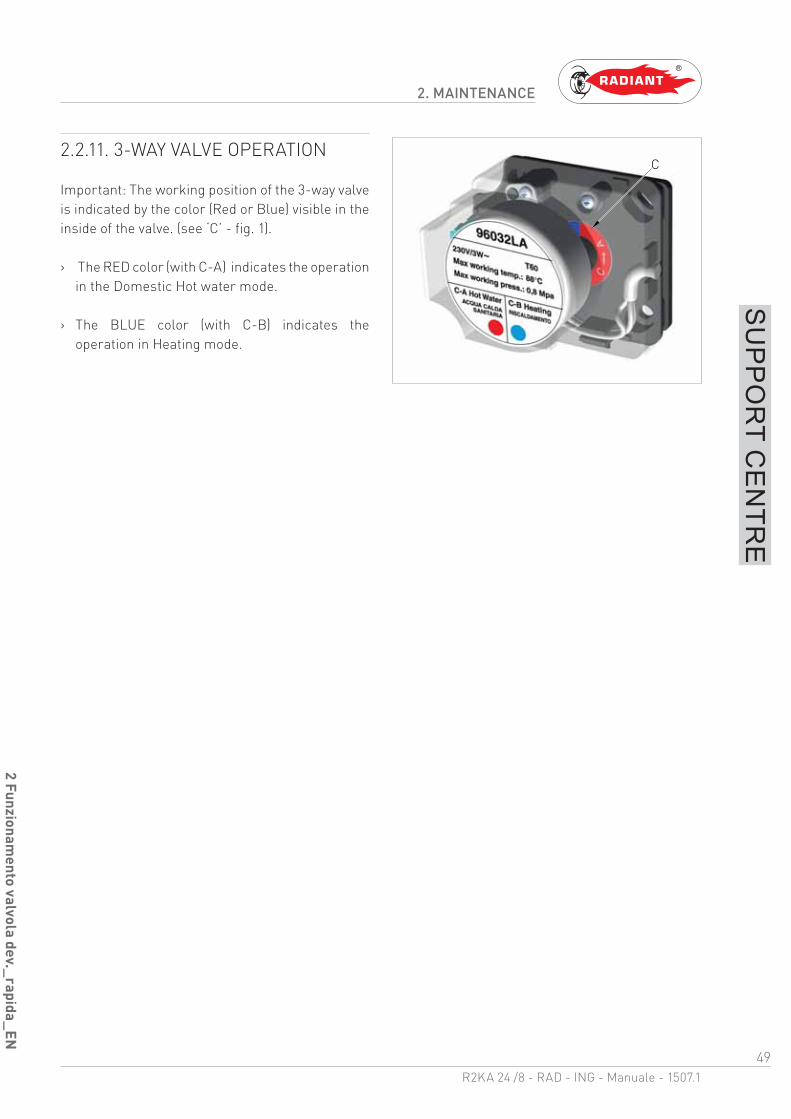
2.2.11. 3-WAY VALVE OPERATION
Important: The working position of the 3-way valve is indicated by the color (Red or Blue) visible in the inside of the valve. (see ‘C’ - fig. 1).
› The RED color (with C-A) indicates the operation in the Domestic Hot water mode.
› The BLUE color (with C-B) indicates the operation in Heating mode.
C
50R2KA 24 /8 - RAD - ING - Manuale - 1507.1
2 Schema elettrico_
R2K
A_
.8_EN
2. MAINTENANCE
SU
PP
OR
T CE
NTR
E
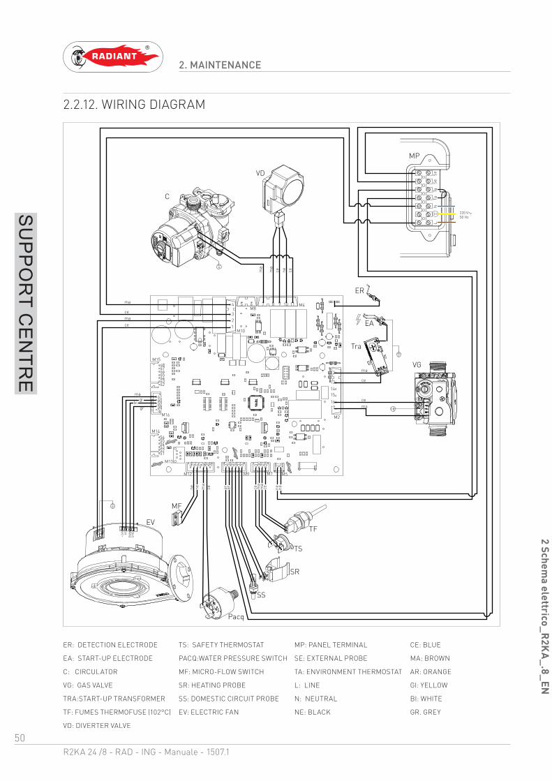
2.2.12. WIRING DIAGRAM
ER: DETECTION ELECTRODE TS: SAFETY THERMOSTAT MP: PANEL TERMINAL CE: BLUE
EA: START-UP ELECTRODE PACQ:WATER PRESSURE SWITCH SE: EXTERNAL PROBE MA: BROWN
C: CIRCULATOR MF: MICRO-FLOW SWITCH TA: ENVIRONMENT THERMOSTAT AR: ORANGE
VG: GAS VALVE SR: HEATING PROBE L: LINE GI: YELLOW
TRA:START-UP TRANSFORMER SS: DOMESTIC CIRCUIT PROBE N: NEUTRAL BI: WHITE
TF: FUMES THERMOFUSE (102°C) EV: ELECTRIC FAN NE: BLACK GR. GREY
VD: DIVERTER VALVE
ma
cemace
ma
ce
magi
bigr
EV
C
ce
ma
cema
EA
VG
Tra
ne cene ma
MF
ER
TS
TF
SR
ar ar ce ma
ma
ce ne ne
220 V50 Hz
MP
Pacq
1110987
12
131415
1617
M12 M9 M7 M5
M2
M4M8
M10
M15
M16
123
4
57
61605958
44 43 42 41 40 39 38 37 36 35 34 33 32 31 30 29 28 27 26
62636465666768
515253545556
5 6
M13
M14L
NSe
SeTa
Ta
+24V HS
PW
MG
ND
VD
ma
ce ne
SS
51R2KA 24 /8 - RAD - ING - Manuale - 1507.1
2 Accesso caldaia_
R2K
A_
.8_EN
2. MAINTENANCE
SU
PP
OR
T CE
NTR
E
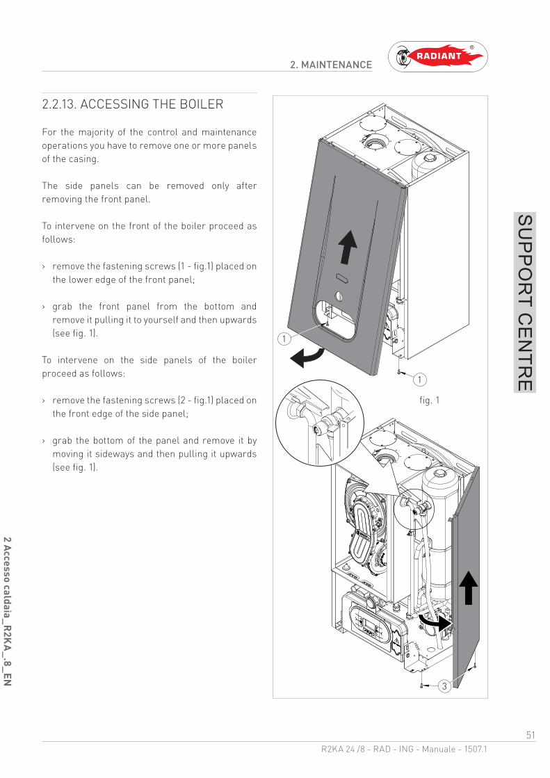
2.2.13. ACCESSING THE BOILER
For the majority of the control and maintenance operations you have to remove one or more panels of the casing.
The side panels can be removed only after removing the front panel.
To intervene on the front of the boiler proceed as follows:
› remove the fastening screws (1 - fig.1) placed on the lower edge of the front panel;
› grab the front panel from the bottom and remove it pulling it to yourself and then upwards (see fig. 1).
To intervene on the side panels of the boiler proceed as follows:
› remove the fastening screws (2 - fig.1) placed on the front edge of the side panel;
› grab the bottom of the panel and remove it by moving it sideways and then pulling it upwards (see fig. 1).
3
1
1
fig. 1
52R2KA 24 /8 - RAD - ING - Manuale - 1507.1
2 Accesso alla scheda elettronica_
EN
2. MAINTENANCE
SU
PP
OR
T CE
NTR
E
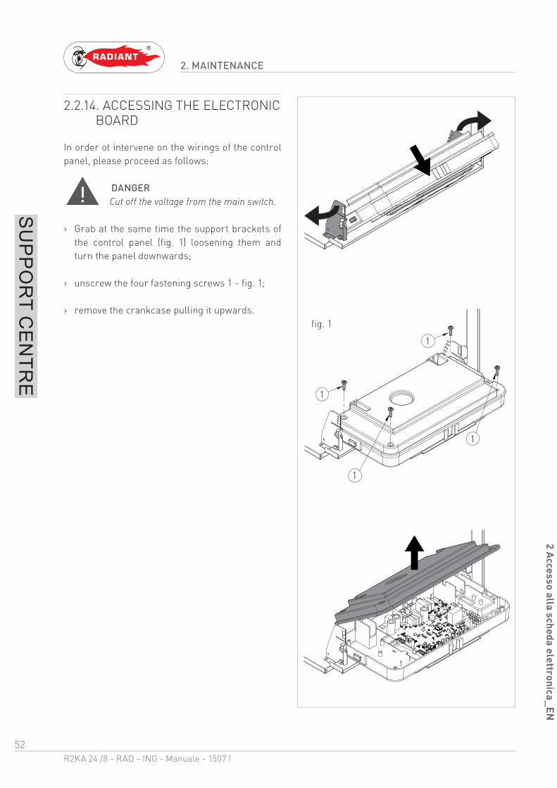
2.2.14. ACCESSING THE ELECTRONIC BOARD
In order ot intervene on the wirings of the control panel, please proceed as follows:
DANGERCut off the voltage from the main switch.
› Grab at the same time the support brackets of the control panel (fig. 1) loosening them and turn the panel downwards;
› unscrew the four fastening screws 1 - fig. 1;
› remove the crankcase pulling it upwards.
1
1
1
1
fig. 1

53R2KA 24 /8 - RAD - ING - Manuale - 1507.1
2 Svuotamento dell'im
pianto_ R2K
A_
.8_EN
2. MAINTENANCE
SU
PP
OR
T CE
NTR
E
2.2.15. SYSTEM EMPTYING
HEATING SYSTEM EMPTYING
Whenever you need to empty the system, proceed as follows:
› switch the boiler to “WINTER” mode and activate it;
› turn off the main power supply switch;
› wait for the boiler to cool down;
› connect a flexible tube to the system emptying outlet and connect the other end of the tube to a suitable discharge;
› turn the discharge tap of the system ‘RS’ (fig. 1);
› open the relief valves of the radiators starting from the one at the top and continuing downwards;
› after draining out all water, close the relief valves of the radiators and the emptying tap.
EMPTYING THE DOMESTIC SYSTEM
If there is freezing risk, you have to empty the domestic system as follows:
› close the main supply tap of the water supply network;
› Joint the water draining pipe and open the cylinder draining tap ‘RB’ (fig.1)
› open all cold and hot water taps;
› after completing all operations, close the cylinder draining tap ‘RB’ (fig.1) and all previously opened water taps.
RSRB
fig. 1

54R2KA 24 /8 - RAD - ING - Manuale - 1507.1
2 Manutenzione del boiler_
R2K
A_
.8_EN
2. MAINTENANCE
SU
PP
OR
T CE
NTR
E
2.2.16. BOILER MAINTENANCE
It’s necessary to check and replace the magnesium anode after a year or more frequently if the quality and the water worn require it.
In order to check the anode functioning it’s necessary to open the cap ‘V’ (fig.1) situated on the top of the boiler.
If during this operations there is a water leak, the anode has to be replaced because worn.
V
fig. 1

55R2KA 24 /8 - RAD - ING - Manuale - 1507.1
2 Codici di segnalazione anomalie_com
binata_MIAH4_EN
2. MAINTENANCE
SU
PP
OR
T CE
NTR
E
2.2.17. FAULT SIGNALLING CODES
To view the last 5 fault signalling codes chronologically, starting with the most recent one, activate the ‘OFF’ mode by pressing the FUNCTION ‘ ’ key and hold the key INFO ‘ ’ for 5 seconds. Use keys ‘
’ and ‘ ’ of the heating circuit to scroll through the list of saved faults. To reset the fault history press the RESET ‘ ’ key. To exit display mode press the INFO ‘ ’ key.
CODE FAULT POSSIBLE CAUSE SOLUTION RESET
E01 FLAME BLOCK NO FLAME LIGHT UP MANUAL RESET
(PRESS THE RESET
‘ ’ KEY).GAS MISSING; CHECK THE ADDUCTION NETWORK;
MASS OR BROKEN START-
UP ELECTRODE;
REPLACE IT;
GAS VALVE BROKEN; REPLACE IT;
SLOW LIGHT UP TOO LOW
ADJUSTMENT;
ADJUST MINIMUM OR SLOW LIGHT UP;
VALVE INFEED PRESSURE
TOO HIGH (ONLY FOR GPL
BOILERS).
CHECK THE MAXIMUM ADJUSTMENT
PRESSURE
WITH FLAME LIGHT UP
NEUTRAL AND PHASE
INVERTED POWER SUPPLY;
PROPERLY CONNECT THE POWER
SUPPLY;
DETECTION ELECTRODE
BROKEN;
REPLACE IT;
DETECTION ELECTRODE
CABLE DISCONNECTED.
CHECK THE WIRING.
ELECTRICAL CURRENT
PHASE-PHASE
IF THE TENSION MEASURES BETWEEN
NEUTRAL AND GROUND IS ALMOST
EQUAL TO THE ONE MEASURED
BETWEEN PHASE AND GROUND, YOU
HAVE TO INSTALL A PHASE-PHASE
TRANSFORMER KIT (COD. 88021LA)

56R2KA 24 /8 - RAD - ING - Manuale - 1507.1
2 Codici di segnalazione anomalie_com
binata_MIAH4_EN
2. MAINTENANCE
SU
PP
OR
T CE
NTR
E
CODE FAULT POSSIBLE CAUSE SOLUTION RESET
E02 SAFETY THERMOSTAT
(95°C)
THERMOSTAT CABLE
DISCONNECTED;
CHECK THE WIRING: MANUAL RESET
(PRESS THE RESET
‘ ’ KEY).
BROKEN THERMOSTAT. REPLACE IT.
E03 FUMES SAFETY
THERMOFUSE (102°C)
THERMOFUSE BROKEN; REPLACE IT; MANUAL RESET
(PRESS THE RESET
‘ ’ KEY).THERMOFUSE CABLE
DISCONNECTED.
CHECK THE WIRING.
E04 WATER MISSING IN THE
SYSTEM
INSUFFICIENT WATER
PRESSURE INSIDE THE SYSTEM
(LOWER THAN 0.3 BAR);
LOAD THE SYSTEM; AUTOMATIC.
WATER PRESSURE SWITCH
CABLE DISCONNECTED;
CHECK THE WIRING;
WATER PRESSURE SWITCH
BROKEN.
REPLACE IT.
E05 HEATING PROBE BROKEN OR INCORRECTLY
CALIBRATED PROBE
(RESISTANCE VALUE 10
KOHM AT 25 °C NTC);
REPLACE IT; AUTOMATIC.
DISCONNECTED OR WET
PROBE CONNECTOR.
CHECK THE WIRING.
E06 DOMESTIC CIRCUIT
PROBE
BROKEN OR INCORRECTLY
CALIBRATED PROBE
(RESISTANCE VALUE 10
KOHM AT 25 °C NTC);
REPLACE IT; AUTOMATIC.
DISCONNECTED OR WET
PROBE CONNECTOR.
CHECK THE WIRING.
E15 RETURN PROBE BROKEN OR INCORRECTLY
CALIBRATED PROBE
(RESISTANCE VALUE 10
KOHM AT 25 °C NTC);
REPLACE IT; AUTOMATIC.
DISCONNECTED OR WET
PROBE CONNECTOR.
CHECK THE WIRING.
57R2KA 24 /8 - RAD - ING - Manuale - 1507.1
2 Codici di segnalazione anomalie_com
binata_MIAH4_EN
2. MAINTENANCE
SU
PP
OR
T CE
NTR
E
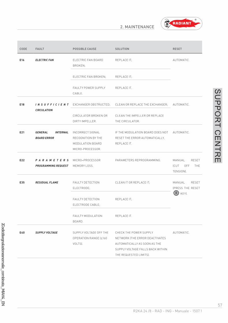
CODE FAULT POSSIBLE CAUSE SOLUTION RESET
E16 ELECTRIC FAN ELECTRIC FAN BOARD
BROKEN;
REPLACE IT; AUTOMATIC.
ELECTRIC FAN BROKEN; REPLACE IT;
FAULTY POWER SUPPLY
CABLE.
REPLACE IT.
E18 I N S U F F I C I E N T
CIRCULATION
EXCHANGER OBSTRUCTED; CLEAN OR REPLACE THE EXCHANGER; AUTOMATIC.
CIRCULATOR BROKEN OR
DIRTY IMPELLER.
CLEAN THE IMPELLER OR REPLACE
THE CIRCULATOR.
E21 GENERAL INTERNAL
BOARD ERROR
INCORRECT SIGNAL
RECOGNITION BY THE
MODULATION BOARD
MICRO-PROCESSOR.
IF THE MODULATION BOARD DOES NOT
RESET THE ERROR AUTOMATICALLY,
REPLACE IT.
AUTOMATIC.
E22 P A R A M E T E R S
PROGRAMMING REQUEST
MICRO=PROCESSOR
MEMORY LOSS.
PARAMETERS REPROGRAMMING. MANUAL RESET
(CUT OFF THE
TENSION).
E35 RESIDUAL FLAME FAULTY DETECTION
ELECTRODE;
CLEAN IT OR REPLACE IT; MANUAL RESET
(PRESS THE RESET
‘ ’ KEY).
FAULTY DETECTION
ELECTRODE CABLE;
REPLACE IT;
FAULTY MODULATION
BOARD.
REPLACE IT.
E40 SUPPLY VOLTAGE SUPPLY VOLTAGE OFF THE
OPERATION RANGE ( 160
VOLTS).
CHECK THE POWER SUPPLY
NETWORK (THE ERROR DEACTIVATES
AUTOMATICALLY AS SOON AS THE
SUPPLY VOLTAGE FALLS BACK WITHIN
THE REQUESTED LIMITS).
AUTOMATIC.
58R2KA 24 /8 - RAD - ING - Manuale - 1507.1
2 Codici di segnalazione funzioni attive_accumulo_M
IAH4_EN
2. MAINTENANCE
SU
PP
OR
T CE
NTR
E
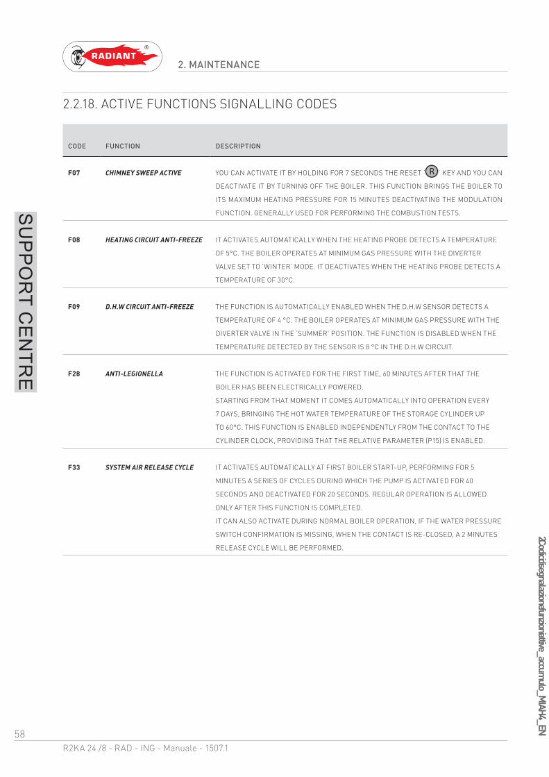
2.2.18. ACTIVE FUNCTIONS SIGNALLING CODES
CODE FUNCTION DESCRIPTION
F07 CHIMNEY SWEEP ACTIVE YOU CAN ACTIVATE IT BY HOLDING FOR 7 SECONDS THE RESET ‘ ’ KEY AND YOU CAN
DEACTIVATE IT BY TURNING OFF THE BOILER. THIS FUNCTION BRINGS THE BOILER TO
ITS MAXIMUM HEATING PRESSURE FOR 15 MINUTES DEACTIVATING THE MODULATION
FUNCTION. GENERALLY USED FOR PERFORMING THE COMBUSTION TESTS.
F08 HEATING CIRCUIT ANTI-FREEZE IT ACTIVATES AUTOMATICALLY WHEN THE HEATING PROBE DETECTS A TEMPERATURE
OF 5°C. THE BOILER OPERATES AT MINIMUM GAS PRESSURE WITH THE DIVERTER
VALVE SET TO ‘WINTER’ MODE. IT DEACTIVATES WHEN THE HEATING PROBE DETECTS A
TEMPERATURE OF 30°C.
F09 D.H.W CIRCUIT ANTI-FREEZE THE FUNCTION IS AUTOMATICALLY ENABLED WHEN THE D.H.W SENSOR DETECTS A
TEMPERATURE OF 4 °C. THE BOILER OPERATES AT MINIMUM GAS PRESSURE WITH THE
DIVERTER VALVE IN THE ‘SUMMER’ POSITION. THE FUNCTION IS DISABLED WHEN THE
TEMPERATURE DETECTED BY THE SENSOR IS 8 °C IN THE D.H.W CIRCUIT.
F28 ANTI-LEGIONELLA THE FUNCTION IS ACTIVATED FOR THE FIRST TIME, 60 MINUTES AFTER THAT THE
BOILER HAS BEEN ELECTRICALLY POWERED.
STARTING FROM THAT MOMENT IT COMES AUTOMATICALLY INTO OPERATION EVERY
7 DAYS, BRINGING THE HOT WATER TEMPERATURE OF THE STORAGE CYLINDER UP
TO 60°C. THIS FUNCTION IS ENABLED INDEPENDENTLY FROM THE CONTACT TO THE
CYLINDER CLOCK, PROVIDING THAT THE RELATIVE PARAMETER (P15) IS ENABLED.
F33 SYSTEM AIR RELEASE CYCLE IT ACTIVATES AUTOMATICALLY AT FIRST BOILER START-UP, PERFORMING FOR 5
MINUTES A SERIES OF CYCLES DURING WHICH THE PUMP IS ACTIVATED FOR 40
SECONDS AND DEACTIVATED FOR 20 SECONDS. REGULAR OPERATION IS ALLOWED
ONLY AFTER THIS FUNCTION IS COMPLETED.
IT CAN ALSO ACTIVATE DURING NORMAL BOILER OPERATION, IF THE WATER PRESSURE
SWITCH CONFIRMATION IS MISSING, WHEN THE CONTACT IS RE-CLOSED, A 2 MINUTES
RELEASE CYCLE WILL BE PERFORMED.

59R2KA 24 /8 - RAD - ING - Manuale - 1507.1
2 Trasformazione tipo gas_
R2K
24_v.2_EN
2. MAINTENANCE
SU
PP
OR
T CE
NTR
E
2.2.19. GAS TYPE TRANSFORMATION
ATTENTIONMake sure that the gas adduction tube is
suitable for the new type of fuel with which the boiler is supplied.
FOR TRANSFORMATION INTO METHANE GAS PROCEED AS FOLLOWS:
› loosen the two screws ‘1’ (fig.1) from the fastening bush, and remove the air suction tube;
› unscrew the tube coupling that connects the gas valve to venturi;
› unscrew the three fastening screws ‘2’ (fig.1) of the venturi ‘V’ (fig.1) using a 10 key, as shown in figure 2;
› replace the venturi with the one suitable for the type of supply gas (cod. 30-00124 for methane), and remount the components following the demounting operations in reverse making sure that gasket ‘G’ is re-assembled as shown in fig.1;
› set the boiler to operate with the new type of gas, changing the value of the parameter P02 ‘GAS TYPE SELECTION’ from the control panel (see chapters ‘DIGITECH CS PARAMETERS TABLE’ and ‘PARAMETERS ACCESSING AND PROGRAMMING’);
› adjust the CO2 combustion value as indicated in chapter ‘CO2 VALUE CHECK AND CALIBRATION’.
1
2
2
V
2
G
fig. 1
fig. 2
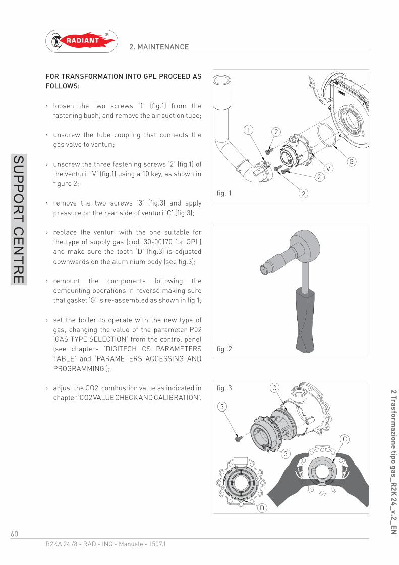
60R2KA 24 /8 - RAD - ING - Manuale - 1507.1
2 Trasformazione tipo gas_
R2K
24_v.2_EN
2. MAINTENANCE
SU
PP
OR
T CE
NTR
E
FOR TRANSFORMATION INTO GPL PROCEED AS FOLLOWS:
› loosen the two screws ‘1’ (fig.1) from the fastening bush, and remove the air suction tube;
› unscrew the tube coupling that connects the gas valve to venturi;
› unscrew the three fastening screws ‘2’ (fig.1) of the venturi ‘V’ (fig.1) using a 10 key, as shown in figure 2;
› remove the two screws ‘3’ (fig.3) and apply pressure on the rear side of venturi ‘C’ (fig.3);
› replace the venturi with the one suitable for the type of supply gas (cod. 30-00170 for GPL) and make sure the tooth ‘D’ (fig.3) is adjusted downwards on the aluminium body (see fig.3);
› remount the components following the demounting operations in reverse making sure that gasket ‘G’ is re-assembled as shown in fig.1;
› set the boiler to operate with the new type of gas, changing the value of the parameter P02 ‘GAS TYPE SELECTION’ from the control panel (see chapters ‘DIGITECH CS PARAMETERS TABLE’ and ‘PARAMETERS ACCESSING AND PROGRAMMING’);
› adjust the CO2 combustion value as indicated in chapter ‘CO2 VALUE CHECK AND CALIBRATION’.
1
2
2
V
2
G
3
3
D
C
C
fig. 1
fig. 2
fig. 3

the operations described in this section are addressed to
all those who will use the machine. The machine must be
used and accessed only by qualified operators that fully
read and understood the User section, paying particular
attention to the warnings.
3. USER SECTION

62R2KA 24 /8 - RAD - ING - Manuale - 1507.1
3 Avvertenze generali per l'utilizzo_
EN
3. USE
US
ER
3.1. USE
3.1.1. GENERAL USE WARNINGS
WARNINGBefore starting the boiler the User must
make sure that the First start-up certificate has the stamp of the technical Support Centre proving the testing and the first start-up of the boiler.
WARNINGTo validate the warranty, the boiler must
be started by a technical Support Centre authorized by RADIANT no later than 30 days from the date of installation.
WARNINGIn order to take advantage of the guarantee
provided by the manufacturer, the customer should carefully and exclusively observe the instructions given in the USER section of the manual.
ATTENTIONThis machine may be used only for the
purpose for which it has been designed: heat water to a temperature below boiling point at atmospheric pressure. Any other use is considered wrong and dangerous. The manufacturer is excluded from any contractual or out of contract responsibility for damage caused to people, animals or property due to incorrect use.
DANGERThe boiler should not be used by persons
(including children) with reduced physical, sensory or mental capacities or without suitable knowledge or experience unless they are instructed on the device use or monitored by a person responsible for their safety.
DANGERDO NOT obstruct the air vents of the
location in which the gas device is installed to prevent the formation of toxic explosive mixes.
DANGERIf you sense a gas odour in the location in
which the boiler is installed, proceed as follows:
› DO NOT use electrical switches, the telephone or any other device that might generate electrical discharges or sparks;
› Immediately open all doors and windows to create an air exchange that can quickly clean the location;
› Close the gas valves;
› Request immediate intervention of qualified staff.
DANGERThe use of the electrical power boiler
implies respecting some fundamental rules such as:
› DO NOT touch the device with wet and/or humid parts and/or with bare feet;
› DO NOT pull the electrical cables;
› DO NOT leave the device exposed to atmospheric agents (rain, sun, etc.) unless specifically intended;
› in case of cable damage, turn off the device and contact qualified professional staff to replace it.
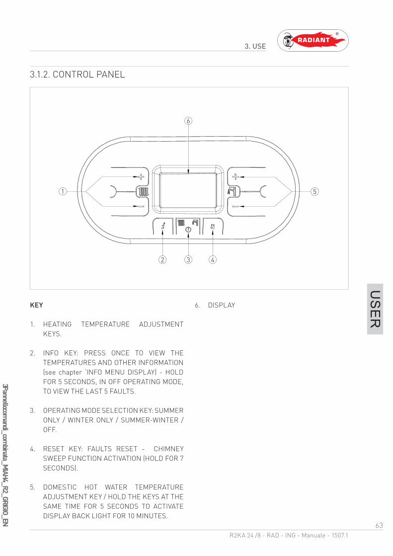
63R2KA 24 /8 - RAD - ING - Manuale - 1507.1
3 Pannello comandi_com
binata_MIAH4_R2_GRIGIO_EN
3. USE
US
ER
3.1.2. CONTROL PANEL
KEY
1. HEATING TEMPERATURE ADJUSTMENT KEYS.
2. INFO KEY: PRESS ONCE TO VIEW THE TEMPERATURES AND OTHER INFORMATION (see chapter ‘INFO MENU DISPLAY) - HOLD FOR 5 SECONDS, IN OFF OPERATING MODE, TO VIEW THE LAST 5 FAULTS.
3. OPERATING MODE SELECTION KEY: SUMMER ONLY / WINTER ONLY / SUMMER-WINTER / OFF.
4. RESET KEY: FAULTS RESET - CHIMNEY SWEEP FUNCTION ACTIVATION (HOLD FOR 7 SECONDS).
5. DOMESTIC HOT WATER TEMPERATURE ADJUSTMENT KEY / HOLD THE KEYS AT THE SAME TIME FOR 5 SECONDS TO ACTIVATE DISPLAY BACK LIGHT FOR 10 MINUTES.
6. DISPLAY
51
6
2 3 4

64R2KA 24 /8 - RAD - ING - Manuale - 1507.1
3 Icone del display_com
binata_M
IAH
4_EN
3. USE
US
ER
3.1.3. DISPLAY ICONS
KEY
1. INDICATION OF PARAMETER NUMBER OR DISPLAYED INFO CODE
2. PARAMETERS PROGRAMMING FUNCTION ACTIVE
3. SIGNALLING CONNECTED SOLAR BOARD / SOLAR COLLECTOR TEMPERATURE DISPLAY (d5)
4. SOLAR PUMP ACTIVE
5. BOILER LOWER TEMPERATURE DISPLAY (d6) / BOILER UPPER TEMPERATURE DISPLAY (d7)
6. EXTERNAL PROBE INSTALLED / EXTERNAL PROBE TEMPERATURE (d1)
7. TEMPERATURE DISPLAY / SET POINT / PARAMETER VALUE
8. OPEN THERM COMMUNICATION PRESENT (REMOTE CONTROL / AREA CONTROL UNIT)
9. INSUFFICIENT SYSTEM WATER PRESSURE SIGNALLING
10. FLAME PRESENT SIGNALLING / IT ALSO INDICATES, ON 3 PERCENTAGE LEVELS, THE MODULATING POWER LEVEL OF THE BOILER (fig.2)
11. OPERATION IN DOMESTIC MODE ENABLED
12. ERROR DISPLAY THAT CAN BE RESET
13. OFF OPERATING MODE
14. ERROR DISPLAY THAT CAN NOT BE RESET
15. OPERATION IN HEATING MODE ENABLED
4 5 6 7
9
10
11121314
15
1
2
3 8
≤ 33% >33%<66% >66%<100%
fig. 1
fig. 2

65R2KA 24 /8 - RAD - ING - Manuale - 1507.1
3 Visualizzazioni del menù Info_
MIA
H4_
EN
3. USE
US
ER
3.1.4. INFO MENU DISPLAY DATA
To view the boiler data from info menu you just have to press the INFO ‘ ’ key. The info code will be displayed on the left side of the screen and its relative value will be displayed on the centre of the screen. Use keys ‘ ’ and ‘ ’ of the heating circuit to scroll through the list of displayed data. To exit display mode press the INFO ‘ ’ key.
LIST OF DISPLAYED DATA
INFO CODE ICON DESCRIPTION
d0 DOMESTIC CIRCUIT PROBE TEMPERATURE
d1 EXTERNAL PROBE TEMPERATURE
d2 FAN SPEED
d3 BOTTOM AREA PROBE TEMPERATURE [IF AREA BOARD INSTALLED]
d4 RETURN PROBE TEMPERATURE
d5 SOLAR COLLECTOR TEMPERATURE [IF SOLAR BOARD INSTALLED] (SCS)
d6 SOLAR BOILER TEMPERATURE (BOTTOM) [IF SOLAR BOARD INSTALLED] (SBSI)
d7 SOLAR BOILER TEMPERATURE (TOP) [IF SOLAR BOARD INSTALLED] (SBSS)
d8 SOLAR COLLECTOR PROBE TEMPERATURE 2 [IF SOLAR BOARD INSTALLED] (SCS2)
d9 EXTRA SOLAR BOILER TEMPERATURE [IF SOLAR BOARD INSTALLED] (SBS3)

66R2KA 24 /8 - RAD - ING - Manuale - 1507.1
3 Accensione_Modalità di funzionam
ento_Antigelo_MIAH4_M
IAH6_EN
3. USE
US
ER
3.1.5. START-UP
Before starting the boiler make sure that it is powered and that the gas tap below the boiler is open.
To start the boiler press the function key ‘’ and select the desired operating mode. If the symbol is displayed fixed, it means that the function was activated.
3.1.6. OPERATING MODE
SUMMER MODE
In this mode the boiler meets only the demands of domestic hot water.
To switch the boiler to SUMMER operating mode, press the function key ‘ ’, the symbol ‘ ’ will appear fixed on the display, indicating that the function is enabled.
Whenever hot domestic water is needed the automatic start-up system will start the burner; this is indicated by displaying the symbol ‘ ’ blinking.
ONLY HEATING MODE
In this mode the boiler meets only the demands of heating.
To switch the boiler to ONLY HEATING operating mode, press the function key ‘ ’, the symbol ‘
’ will appear fixed on the display, indicating that the function is enabled.
Whenever heating energy is needed to heat the rooms the automatic start-up system will start the burner; this is indicated by displaying the symbol ‘
’ blinking.
WINTER MODE
In this mode the boiler meets the demands of heating and of domestic hot water.
To switch the boiler to WINTER operating mode, press the function key ‘ ’, the symbols ‘ and ’ will appear fixed on the display, indicating that the function is enabled.
Whenever heating energy and domestic hot water are needed the automatic start-up system will start the burner; this is indicated by displaying the symbol ‘ e ’ blinking.
ADJUSTING THE HEATING TEMPERATURE
You can adjust the temperature using keys ‘ ’ and ‘ ’ of the heating circuit :
· press key ‘ ’ to decrease the temperature.
· press key ‘ ’ to increase the temperature.
The heating temperature adjustment field ranges from 30 °C to 80 °C (25 °C – 45 °C for floor systems).
DOMESTIC HOT WATER TEMPERATURE ADJUSTMENT
You can adjust the temperature using keys ‘ ’ and ‘ ’ of the domestic circuit :
· press key ‘ ’ to decrease the temperature.
· press key ‘ ’ to increase the temperature.
The hot domestic water temperature adjustment field ranges from 35 °C to 60 °C.
OFF MODE
In this mode the boiler no longer meets the heating and domestic hot water demands, the anti-freeze,
67R2KA 24 /8 - RAD - ING - Manuale - 1507.1
3 Accensione_Modalità di funzionam
ento_Antigelo_MIAH4_M
IAH6_EN
3. USE
US
ER
pump anti-locking and diverter valve anti-locking systems still remain active.
To switch the boiler to OFF operating mode, press the function key ‘ ’, the symbol ‘ ’ will appear fixed on the display, indicating that the function is enabled (for non condensing models will appear the message ‘OFF’).
If the boiler was previously running, it will be turned off and the post-ventilation and post-circulation functions will be enabled.
If you have to deactivate the boiler for a long period of time, proceed as follows:
› contact the Technical support centre that will empty the water system, where no anti-freeze is intended, and will cut off the power, water and gas supply.
› Or leave the boiler in OFF operating mode keeping active the electrical and gas supplies so that the anti-freeze function may activate.
3.1.7. INFORMATIONAL NOTE ON ANTI-FREZZE FUNCTION
The boiler is protected against freezing thanks to the electronic board preparation with functions that start the burner and heat the concerned parts when their temperature goes below the minimum pre-set values.
WARNINGThis function is available only if:
› the boiler is powered;
› the gas supply is open;
› the pressure of the system is proper;
› the boiler is not blocked.
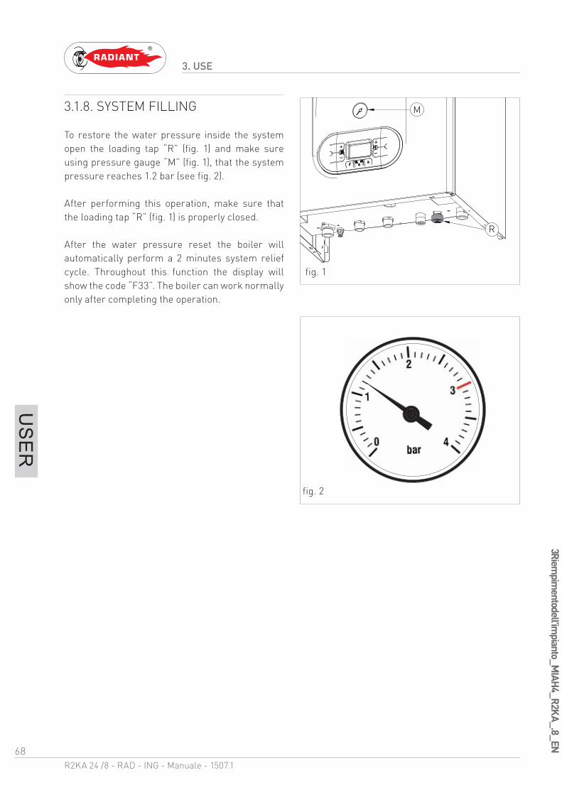
68R2KA 24 /8 - RAD - ING - Manuale - 1507.1
3 Riempim
ento dell'impianto_M
IAH4_R2K
A_.8_EN
3. USE
US
ER
3.1.8. SYSTEM FILLING
To restore the water pressure inside the system open the loading tap “R” (fig. 1) and make sure using pressure gauge “M” (fig. 1), that the system pressure reaches 1.2 bar (see fig. 2).
After performing this operation, make sure that the loading tap “R” (fig. 1) is properly closed.
After the water pressure reset the boiler will automatically perform a 2 minutes system relief cycle. Throughout this function the display will show the code “F33”. The boiler can work normally only after completing the operation.
M
R
fig. 1
fig. 2

69R2KA 24 /8 - RAD - ING - Manuale - 1507.1
3 Codici di segnalazione anomalie_com
bi_MIAH4_EN
3. USE
US
ER
3.1.9. FAULT SIGNALLING CODES
The boiler might signal some faults by displaying a code. Below you have a list of the codes and of the operations to be performed in order to unlock the boiler.
CODE ICON FAULT INTERVENTION
E01 FLAME BLOCK MAKE SURE THAT THE BOILER AND CONTACTOR GAS VALVES
ARE OPEN.
PRESS THE RESET ‘ ’ BUTTON ON THE CONTROL PANEL TO
RESET THE FAULT, AS SOON AS THE ERROR CODE DISAPPEARS
FROM THE DISPLAY, THE BOILER WILL START AUTOMATICALLY.
IF THE BLOCK PERSISTS CONTACT THE TECHNICAL SUPPORT
CENTRE.
E02 SAFETY THERMOSTAT (95 °C) PRESS THE RESET ‘ ’ BUTTON ON THE CONTROL PANEL TO
RESET THE FAULT, AS SOON AS THE ERROR CODE DISAPPEARS
FROM THE DISPLAY, THE BOILER WILL START AUTOMATICALLY.
IF THE BLOCK PERSISTS CONTACT THE TECHNICAL SUPPORT
CENTRE.
E03 FUMES SAFETY THERMOFUSE (102 °C) CONTACT THE TECHNICAL SUPPORT CENTRE.
E04 WATER MISSING IN THE SYSTEM IF THE SYSTEM PRESSURE IS BELOW 1.2 BAR, FILL THE SYSTEM
AS DESCRIBED IN CHAPTER “SYSTEM FILLING”.
IF THE BLOCK PERSISTS CONTACT THE TECHNICAL SUPPORT
CENTRE.
E05 HEATING PROBE CONTACT THE TECHNICAL SUPPORT CENTRE.
E06 DOMESTIC CIRCUIT PROBE CONTACT THE TECHNICAL SUPPORT CENTRE.
E15 RETURN PROBE CONTACT THE TECHNICAL SUPPORT CENTRE.
E16 ELECTRIC FAN CONTACT THE TECHNICAL SUPPORT CENTRE.
E18 INSUFFICIENT CIRCULATION CONTACT THE TECHNICAL SUPPORT CENTRE.
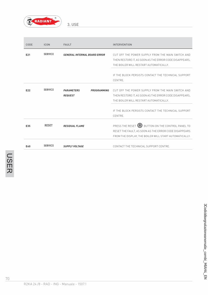
70R2KA 24 /8 - RAD - ING - Manuale - 1507.1
3 Codici di segnalazione anomalie_com
bi_MIAH4_EN
3. USE
US
ER
CODE ICON FAULT INTERVENTION
E21 GENERAL INTERNAL BOARD ERROR CUT OFF THE POWER SUPPLY FROM THE MAIN SWITCH AND
THEN RESTORE IT, AS SOON AS THE ERROR CODE DISAPPEARS,
THE BOILER WILL RESTART AUTOMATICALLY.
IF THE BLOCK PERSISTS CONTACT THE TECHNICAL SUPPORT
CENTRE.
E22 PARAMETERS PROGRAMMING
REQUEST
CUT OFF THE POWER SUPPLY FROM THE MAIN SWITCH AND
THEN RESTORE IT, AS SOON AS THE ERROR CODE DISAPPEARS,
THE BOILER WILL RESTART AUTOMATICALLY.
IF THE BLOCK PERSISTS CONTACT THE TECHNICAL SUPPORT
CENTRE.
E35 RESIDUAL FLAME PRESS THE RESET ‘ ’ BUTTON ON THE CONTROL PANEL TO
RESET THE FAULT, AS SOON AS THE ERROR CODE DISAPPEARS
FROM THE DISPLAY, THE BOILER WILL START AUTOMATICALLY.
E40 SUPPLY VOLTAGE CONTACT THE TECHNICAL SUPPORT CENTRE.
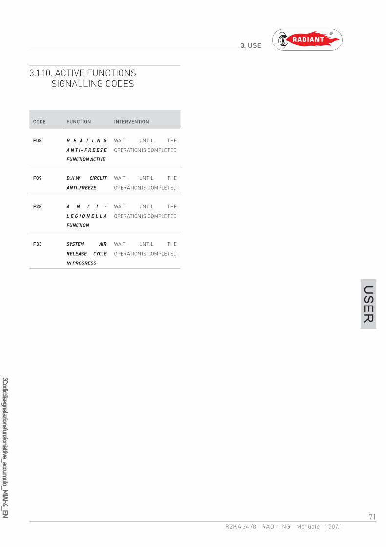
71R2KA 24 /8 - RAD - ING - Manuale - 1507.1
3 Codici di segnalazione funzioni attive_accumulo_M
IAH4_EN
3. USE
US
ER
3.1.10. ACTIVE FUNCTIONS SIGNALLING CODES
CODE FUNCTION INTERVENTION
F08 H E A T I N G
A N T I - F R E E Z E
FUNCTION ACTIVE
WAIT UNTIL THE
OPERATION IS COMPLETED
F09 D.H.W CIRCUIT
ANTI-FREEZE
WAIT UNTIL THE
OPERATION IS COMPLETED
F28 A N T I -
L E G I O N E L L A
FUNCTION
WAIT UNTIL THE
OPERATION IS COMPLETED
F33 SYSTEM AIR
RELEASE CYCLE
IN PROGRESS
WAIT UNTIL THE
OPERATION IS COMPLETED
72R2KA 24 /8 - RAD - ING - Manuale - 1507.1
3 Manutenzione_
Pulizia_
Smaltim
ento_EN
3. USE
US
ER
3.1.11. MAINTENANCE
To ensure proper boiler safety and efficiency, please contact RADIANT technical support network to check the device every year.
An accurate maintenance should improve system management.
3.1.12. COVER CLEANING
Clean the cover of the device using a wet cloth and come neutral soap.
WARNINGDO NOT use abrasive or powder detergents
as they might damage the plastic cover and control elements.
3.1.13. DISPOSAL
The boiler and all its accessories must be differentiated, suitably disposed of in accordance with the standards in force.
The use of the symbol WEEE (Waste Electrical and Electronic Equipment) shows that this
product can not be dismantled as domestic waste. Proper dismantle of this product helps preventing potentially negative consequences on human health and environment.


RADIANT BRUCIATORI S.p.A.
Via Pantanelli, 164/166 - 61025 - Montelabbate (PU)