search.jsp?R=19660023668 2018-02-10T13:00:10+00:00Z · A. Investigate the feasibility of winding...
45
https://ntrs.nasa.gov/search.jsp?R=19660023668 2018-05-27T19:10:20+00:00Z
Transcript of search.jsp?R=19660023668 2018-02-10T13:00:10+00:00Z · A. Investigate the feasibility of winding...

https://ntrs.nasa.gov/search.jsp?R=19660023668 2018-05-27T19:10:20+00:00Z
4’
NASA CR-517
PRECISION WINDING OF CYLINDRICAL COMPOSITES
WITH SHAPED GLASS FILAMENTS
By Richard A. Humphrey
Distribution of this report is provided in the interest of information exchange. Responsibility for the contents resides in the author or organization that prepared it.
Prepared under Contract No. NASw- 1100 by DeBELL & RICHARDSON, INC.
Hazardville, Conn.
for
NATIONAL AERONAUTICS AND SPACE ADMINISTRATION
For sale by the Clearinghouse for Federal Scientific and Technical Information Springfield, Virginia 22151 - Price $2.00

. c
FOREWORD
This is Part I of the final report on Contract NASw-1100, "Hollow Multipartitianed
Ceramic Structures." It describes a ccmtinuation of work done under Contract NASw-672,
same title, whose final report issued as NASA CR-142. Part 11, NASA CR-518, "Initiation
of Failure Mechanisms in Glass-Resin Compgsites" by William J, Eakins is being
issued concurrently,
FRECEDING PAGE BLANK NOT FILMED.
iii

ABSTRACT
During the continuation of the f i rs t year ' s effort on forming shaped
and hollow glass filaments, the process was refined, Precision windings
were made to obtain close packing from rectangular microtape, both solid
and hollow, while hollow hexagonal fiber was wound into a micro-honeycomb.
Substantial mechanical properties data were developed on 2.3"
diameter tubes precision wound from solid microtape into 90% by volume
glass structures.
water and modulus of elasticity values the same as the glass; namely,
10 x 10 psi.
windings were as high as 25,000 psi.
These displayed no room temperature permeability to
6 A x i a l strengths of the tubes with only circumferential
PRECEDING PAGE BLANK NOT FILMED.
V

. TABLE OF CONTENTS
. Page
INTRODUCTION and SUMMARY
EQUIPMENT Precision Lathe Winder Preform Feeder Furnace Furnace and Feeder Assembly Typical Forming and Winding Procedure
DISCUSSION Microtape Filaments with Other Cross Sections Shaped Fibers f rom Polymers and Fused Silica Propert ies of Structures Wound from Shaped Filaments
Specimen Design Tes t Method Discussion of Test Results
CONCLUSIONS Recommendations for Future Work
BIBLIOGRAPHY
APPENDIX A - Analysis of the Poisson's Ratio Effect on a Thin Composite in a Biaxial S t ress Field
LIST OF TABLES
Table I-A - Construction and Type of Tes t
Table I -B - Test Results
Table 11 - Resin System Formulations
FIGURES
1
3 3 6 7 8
10
11 12 14 18 18 18 19 21
29 30
32
39
33
34
35
36

INTRODUCTION and SUMMARY
The statement of work comprises a concise expression of the objectives
of this contract.
A. Investigate the feasibility of winding resin-wet filaments and tapes
on a mandrel in a close uniform spacing arrangement.
Fo rm multiple filament and tape structures.
Investigate methods of forming complex objects with the new c ross
section filaments formed under "B" above.
Continue to investigate the failure initiation mechanism in glass-
r e sin composite s.
B .
C .
D.
Major advances were made in both ItA" and "D" above while some
progress was made in llBll and "C".
NASW-1100 is a continuation of the original contract NASw-672. The
first y e a r ' s effort, described in the final report and issued a s NASA CR-142 ( l ) ,
was a broad program to explore the capabilities of the preform attenuation
process in the forming of a vast number of different shaped c ross section glass
fibers.
refinement to get some selected shaped filaments into structures in precise
placement in order to determine properties of structures made from shaped
fi laments.
The second year ' s effort, described in this report, was a program of

The following is a list of the second year ' s accomplishments:
1.
2.
3.
4.
5 ,
6 .
7.
8.
9.
Designed and installed new improved preform feeding mechanism.
Demonstrated feasibility of preform attenuation technique for the
drawing of organic polymers in solid and hollow round filaments
as well as simple shaped filaments.
Refined shaped glass filament forming technique to yield shaped
filament which maintains constant dimensions over long lengths.
Determined the variables requiring control to; (a) make constant
dimension shaped filament, and (b) precision wind such a filament.
Procured new lathe with precision feed screw.
installed modifications to make lathe into precision tube winder.
Utilized new preform feeder and new lathe winder to make tubular
structures from microtape.
Obtained mechanical properties on tubes precision wound f rom
solid and hollow microtape, determining circumferential and axial
modulus and strength properties.
Made precision windings of hollow, hexagonal filaments and deter - mined physical properties.
Shipped shaped glass filaments to other investigators.
Designed and
2

. 10. Studied the micromechanics of resin block and single microtape
embedments which provided an opportunity to analyze internal and
external s t r e s s loading and failure analyses'in both circular fila-
ment wound and microtape wound materials. The effect of external
loading of castings on their water absorption was alsQ examined.
The results of this study a r e presented in P a r t 11 of t h i s final report.
EQUIPMENT
The de signing, procuring, modifying and installing of special equipment
to form and precisely wind shaped filaments during this year has contributed a
great deal toward the refining of the process for making s t ructures from shaped
filaments.
Pr eci sion Lathe Winder ~~ ~~~~~ ~~
The new winder has been made by modifying a Clausing 10" x 36" lathe.
Instead of the usual lathe head stock, the mandrel is driven by a DC variable
speed motor which is mounted on a platform along with the lathe tail stock.
This platform, fabricated from two 4" aluminum I-beams and a 3/8" thick
aluminum plate, is anchored to the lathe saddle carriage.
not used.
gears and the feed screw.
control so they will run at the same speed.
the t raverse , a l imit switch is located which reverses the direction of rota-
tion of only the t raverse motor with the mandrel drive motor continuing in the
The cross feed is
A second identical DC motor drives the carr iage through the change
Both of these motors a r e driven from a common
At both the right and left ends of
3

same direction.
wound onto the mandrel without stopping.
In this way, layer after layer of shaped filament can be
Figures 1 and 2, which may be unfolded to permit ready comparison
with the details in the text, a r e views of this winder.
to right, the operator has within reach the winder controls, the mandrel
In Figure 1, from left
tachometer, the lathe apron controls; and in the upper center, the filament
guides and microscope monitor.
controls and, a t the far right, the furnace temperature controls and precision
At the upper right center a r e the feeder
portable potentiometer for chamber temperature monitoring. Figure 2, the
r ea r view of the lathe winder, shows the microscope at the top for monitoring
filament size, immediately below which the resin i s f i r s t applied. The rigid
guide support, fabricated from square tubing and fastened to the lathe bed,
holds the floating guide and wiper assembly.
at this final guide.
foreground.
Additional resin may be added
The mandrel drive motor and tachometer a r e in the upper
The fabricated mandrel support platform i s fastened to the lathe
saddle carriage.
and the mandrel drive motor a t the near end.
On the platform a r e mounted the tail stock a t the far end
The traversing mQtor, in the
foreground, drives the saddle through the change gears and feed screw.
justable limit switches a r e mounted a t the back On rails fastened to the lathe
bed.
controls for the two winder motors .
Ad-
Across the back of the lathe pedestals, below, can be seen the automatic
4

The precision winder is designed to operate with a broad range of
mandrel sizes, speeds and t raverse ra tes to utilize many different filament
sizes and shapes. The following list illustrates this versatility.
Modified Lathe Winder SPecifications
Maximum length of t raverse 36"
Normal maximum wound structure length 30"
Maximum wound structure diameter 10"
Mandrel diameters available:
fo r nominal 2" pipe 0. D. for NOL ring tubes for making 28" square flat laminates
2. 295" 5. 750" 8. 910"
Mandrel speed; continuously adjustable 50 to 550 RPM
Traverse spacings
Fine, in 26 increments Coarse, in 26 increments
. 00447" to . 0313"
. 0358" to . 250"
By moving the mandrel back and forth beneath a fixed guide, the angle
and length of the filament f rom the furnace across the microscope and the
guide remains constant at all times. Monitoring the size of the filament with
the microscope permits the operator to adjust the speed of the mandrel, and
simultaneously the t raverse rate, maintaining the proper filament size to be
accommodated by the chosen t raverse gap.
5
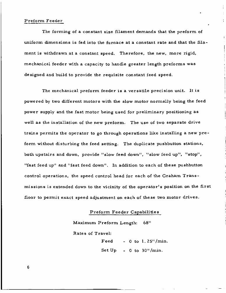
Preform Feeder
The forming
uniform dimensions
of a constant size filament demands that the preform of
i s fed into the furnace at a constant rate and that the fila-
ment is withdrawn a t a constant speed. Therefore, the new, more rigid,
mechanical feeder with a capacity to handle greater length preforms was
designed and build to provide the requisite constant feed speed.
The mechanical preform feeder is a versatile precision unit.
powered by two different motors with the slow motor normally being the feed
power supply and the fast motor being used for preliminary positioning as
well as the installation of the new preform.
trains permits the operator to go through operations like installing a new pre-
form without disturbing the feed setting.
both upstairs and down, provide "slow feed down", "slow feed up", "stop",
"fast feed up" and "fast feed down". In addition to each of these pushbutton
control operations, the speed control head for each of the Graham Trans-
missions i s extended down to the vicinity of the operator 's position on the first
floor to permit exact speed adjustment on each of these two motor drives.
It i s
The use of two separate drive
The duplicate pushbutton stations,
Preform Feeder Capabilities
Maximum Preform Length: 68"
Rates of Travel:
Feed - 0 to l .25I1/min.
Set U p - o to 30"/min.
6
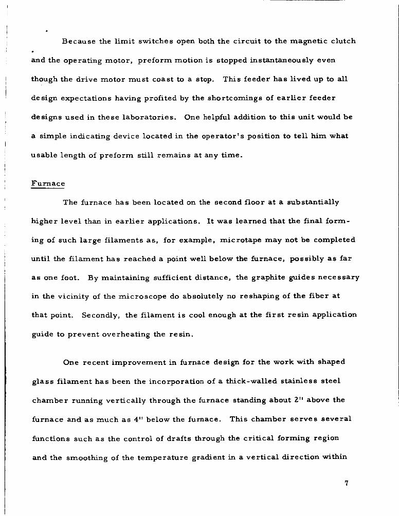
Because the limit switches open both the circuit to the magnetic clutch
and the operating motor, preform motion is stopped instantaneously even
though the drive motor must coast to a stop.
de sign expectations having profited by the shortcomings of ear l ie r feeder
This feeder has lived up to all
designs used in these laboratories.
a simple indicating device located in the operator's position to tell him what
One helpful addition to this unit would be
usable length of preform still remains at any time.
Furnace
The furnace has been located on the second floor a t a substantially
higher level than in ear l ier applications. It was learned that the final form-
ing of such large filaments as , for example, microtape may not be completed
until the filament has reached a point well below the furnace, possibly as far
as one foot.
in the vicinity of the microscope do absolutely no reshaping of the fiber at
that point.
guide to prevent overheating the resin.
By maintaining sufficient distance, the graphite guides necessary
Secondly, the filament is cool enough at the first resin application
One recent improvement in furnace design for the work with shaped
glass filament has been the incorporation of a thick-walled stainless steel
chamber running vertically through the furnace standing about 2" above the
furnace and as much as 4" below the furnace.
functions such as the control of draf ts through the critical forming region
and the smoothing of the temperature gradient in a vertical direction within
This chamber serves several
7

the furnace. In the case of a wide, thin c ross section, such as the microtape
being used at the present time as a model material for precision winding
studies, a wide thin rectangular chamber has worked well.
1 / , ' I thick stainless steel is about 1 /211 wider than the preform on each edge
This chamber of
and has a total thickness of approximately 1 /2" giving about 1 /,I1 between e w h
face of the preform and the inside of the steel chamber. A thermocouple i s
..,al'a .a a:-*- -.L1 v v - A u e ~ u l r t : L L i y to the outside face of the stainless steel chamber to assist in
setting the automatic controller at the proper temperature.
experience on shaped filaments, i t i s well-known that the furnace temperature
F r o m ear l ier
has a profound effect on the c ross sectional shape of the filament.
a null balance, digital set point controller provides information for the
Therefore,
silicon control rectifier unit which yields a furnace temperature constant
within approximately f 1°F.
Furnace and Feeder Assembly
Figures 3 and 4 a r e views on the second floor of the furnace, feeder
and feeder control boxes.
f i r e brick furnace, mounted on vibration isolators, i s oriented so the width
The side view, Figure 3, shows how the insulating
of the preform is parallel to the mandrel on the lathe downstairs. In the
background on the wall a r e the contactors which control magnetic clutches
connecting the slow feed motor o r the fast set-up motor to the feeder as well
as controlling the direction of rotation of the operating motor.
controlled by the pushbutton station at the left , a duplicate of that in the
These a r e
8

operator's position on the lower floor.
feeder guide rods between which is the long screw that drives the feeder yoke.
Against the side wall can be seen the
The reflection from a long, three inch wide s t r ip of g lass can be seen entering
the top of the furnace through some graphite guide blocks.
The front view of the second floor assembly, Figure 4, was made with
the yoke and a preform attached lowered to where it would be i f it were approach-
ing the end of a run on that preform.
the ends of the two silicon carbide heating elements extend out to where the
electrical s t raps a r e connected. The two drive motors can be seen beneath
and to each side of the furnace.
Graham Transmission, thence a magnetic clutch, one of which can be seen
directly beneath the near corner of the furnace. Thus either motor can be
coupled through a right angle drive to the long screw, between the guide rods,
that drives the yoke by means of a split nut. The lower limit switch is appar-
ent about 9'' below the yoke.
the feed direction at the end of a run while an upper l imit switch stops the yoke
at a prese t level to facilitate loading a new preform.
left is the slow feed motor which is of a synchronous induction type to main-
tain a constant feed rate.
the picture to the right, located on the second floor to keep the high current
leads to a minimum length.
Close to the bottom of the furnace chamber
Each of them drives through a variable speed
This switch stops the yoke and the preform in
The motor on the lower
The power transformer f o r the furnace is out of
9

I 1 I 1
I
Typical Forming and Winding Procedure
After preheating the furnace, a preform i s attached to the feeder yoke.
The preform i s then lowered between graphite guides on top of the chamber
far enough into the furnace that a small amount of the preform can act as a
I
1 I I weight below the hot zone to attenuate the preform as it softens. The operator i 1
then descends to the first floor and when the bottom of the preform appears I 1 4
I below the chamber, i t is grasped acd pd?ed downward and. manual drawing is
I I continued until a small enough filament is formed so it can be threaded ac ross I
the microscope guides. The coarse filament is then attached to the end of
the mandrel where the excess mater ia l can accumulate and the mandrel i s
started.
the filament is plied onto the excess end of the mandrel, the operator observes
the filament size through the microscope.
the feed speed of the preform and/or the mandrel speed in order to adjust
the filament size.
and only the mandrel speed i s adjusted.
been achieved, resin flow i s started and the filament i s t ransferred from the
temporary traverse guide to the fixed guide for normal filament winding.
At the same time, carriage motion is started by pulling up the lever on the
apron which closes the split nut onto the feed screw of the lathe.
the winding of a tube on the mandrel should be automatic f rom this point on.
Actually the operator must make frequent minor speed adjustments to com-
pensate for filament size changes.
Shor t ly thereafter, the preform feed motor is also started and while
He has the possibility of changing
Normally the feed speed has been previously established
When the proper filament size has
Theoretically,
As the diameter of the structure being
10
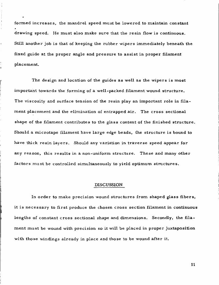
formed increases, the mandrel speed must be lowered to maintain constant
drawing speed. He must also make sure that the resin flow i s continuous.
Still another job is that of keeping the rubber wipers immediately beneath the
fixed guide at the proper angle and pressure to assist in proper filament
placement.
The design and location of the guides as well as the wipers is most
important towards the forming of a well-packed filament wound structure.
The viscosity and surface tension of the resin play an important role in fila-
ment placement and the elimination of entrapped air.
shape of the filament contributes to the glass content of the finished structure.
Should a microtape filament have l a r g e edge beads, fhe structure is bound to
have thick resin layers.
any reason, this results in a non-uniform structure.
factors must be controlled simultaneously to yield optimum structures.
The c ross sectional
Shodd any variation in t raverse speed appear for
These and many other
DISCUSSION
In order to make precision wound structures from shaped glass fibers,
it is necessary to first produce the chosen cross section filament in continuous
lengths of constant c ros s sectional shape and dimensions. Secondly, the fila-
ment must be wound with precision so i t will be placed in proper juxtaposition
with those windings already in place and those to be wound after it.
11

The winding problem is further complicated because some shaped
fibers, to take full advantage of their shape, can only be wound in one direction.
F o r example, a hexagonal fiber cannot be t raversed back and forth in first a
right-hand and then a left-hand helix because the crossovers would prevent
the perfect packing possible with a hexagonal fiber. On the other hand, a fila-
ment with a flat, wide C F O S S section, such as microtape, can be wound con-
&:---- uluuus iy in edge-to-edge fashion for layer after layer since a layer which has
already been wound presents a perfectly smooth cylindrical surface and causes
no interference when a right-hand helix i s wound over a left-hand one and vice
versa .
Mi c r o tape
As a model mater ia l to investigate in depth the problems of precision
winding, i t was decided to use microtape.
microtape w a s being developed- concurrently f o r NASA Lewis Research Center,
Contract No. NAS 3-3647, with the objective of winding it into low permeability
structures. A certain amount of experience had been gained in forming micro-
tape and making precision wound s t ructures f rom it.
This flat thin glass filament called
A great deal of experience had been gained using the 0.0005" x 0.020"
microtape so this size was used at the beginning of this winding study. Even
with all the improved equipment and the accumulated fiber forming and p r e -
cision winding experience, the small microtape was difficult to wind into
100'70 pe rfe ct specimens.
12

As an example, one of the research specimens required for NASA
Lewis is a 0. O 4 O t 1 wall tube, 30" long and 2 . 3 " I. D. To wind a perfect speci-
men with the 0.020" wide microtape requires the drawing of a continuous length
of filament over 11 miles long whose width does not vary more than *O. 0005"
and necessitates placement in the structure to the same tolerance. By micro-
scope monitoring, the mandrel speed can be adjusted to compensate for gradual
width changes; however, sudden fluctuations can be jQst as damaging.
Other investigators (2) have obtained good mechanical properties in
filament wound structures with larger-than- standard diameter round filaments.
A simple analysis showed that laPger microtape filaments could be placed
into a tighter overall structure; that is, one with a lower percentage resin
gap from edge-to-edge while still requiring less cri t ical dimensional tolerances.
Various larger microtape filaments were drawn and a filament about
0. 0015" thick and 0.0601' wide was chosen as a size that could be made con-
sistently to close dimensional tolerances with a good flat cross sectional
shape and with sufficient strength to wind without breaking at the guides nor
at the relatively small diameter mandrel. This larger filament would require
only about 1 -1/2 miles of microtape to make the same size specimen. The
specimen could have an improved structure even though the filament width
tolerance was relaxed to *O. 001" since the precision winder tolerances re-
main the same for any size filament.
13
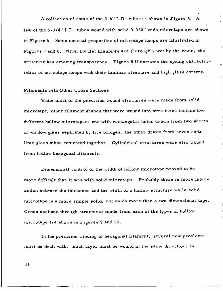
A collection of some of the 2.6" I.D. tubes i s shown in Figure 5. A
few of the 5-3/4" I. D. tubes wound with solid 0.020" wide microtape a r e shown
in Figure 6. Some unusual properties of microtape hoops a r e i l lustrated in
Figures 7 and 8 . When the flat filaments a r e thoroughly wet by the resin, the
structure has amazing transparency. Figure 8 i l lustrates the spring character -
is t ics of microtape hoops with their laminar structure and high glass content.
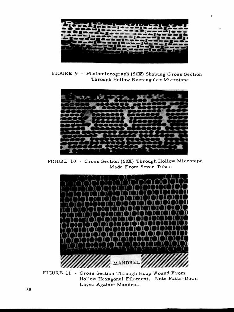
Filaments with Other Cross Sections
While most of the precision wound s t ructures were made from solid
microtape, other filament shapes that were wound into s t ructures include two
different hollow microtapes; one with rectangular holes drawn from two sheets
of window glass separated by five bridges, the other drawn from seven soda-
l ime g la s s tubes cemented together. Cylindrical s t ructures were also wound
f rom hollow hexagonal filaments.
Dimensional control of the width of hollow microtape proved to be
more difficult than it was with solid microtape.
action between the thickness and the width of a hollow structure while solid
microtape is a more simple solid, not much more than a two dimensional tape.
Cross sections through s t ructures made f rom each of the types of hollow
microtape are shown in Figures 9 and 10.
Probably there i s more inter-
In the precision winding of hexagonal filament, several new problems
must be dealt with. Each layer must be wound in the same direction; in
14

order that the filaments can intermesh properly, every layer must be a
helix wound in the same direction as the first layer. F o r example, using
screw thread parlance, all the unidirectionally wound tubes have been pro-
duced in the direction of left-hand threads, which was more convenient to do
on the equipment located here.
In a hexagonal filament wound structure, the f i r s t layer establishes
the spacing for the whole structure.
must be the proper "threads per inch" to match the flat-to-flat size of the
filament in order to produce a perfect micro-honeycomb. Figure 11 is a
photomicrograph of a c ros s section through the wall of a tube wound from
hollow hexagonal filament.
uniform filament size, it i s evident that the f i r s t layer with its flats against
the mandrel established too wide a spacing, with too few threads per inch to
force the subsequent layers to wind with their vertical sides virtually touch-
ing one another.
first layer which positions itself flats down as was wound in subsequent
layers .
lished too wide a spacing for the following layers of the same size filament.
Future work on this problem should u s e a smaller hexagonal filament in the
first layer o r a round filament whose size is chosen to provide proper spacing
for the remainder of the tube.
Stated another way, the first layer
While this wall has a very regular structure with
In this specimen, the same size filament was used in the
The first layer, even if i t s points were touching, would have estab-
15

During the first yea r ' s effort on shaped fibers, no great quantity of
any one shape was required.
filaments could be ground out of a larger piece of glass by hand to make a
long enough preform to prove the technique.
hand, can usually be made from a preform cemented together o r even f rom
one o r more tubes of glass.
Therefore, preforms for various shaped solid
Hollow fibers, on the other
This year , when it was requested that we ship a given quantity of sev-
e ra l different fiber shapes to other NASA contractors, it was decided that
some work should be done on prefusing glass together to make solid preforms
whose c ross sectional shape would be suitable to make such solid f ibers as
an ellipse and a rhombus.
was that of building up long ba r s from long thin sheets of glass of the proper
width to approximate the desired c ros s section.
flat in a furnace and fused together af ter which the bar i s annealed.
forms then look like the illustrations in the calculus to show integration.
small discrete steps on the surfaces virtually disappear upon drawing the fiber
from the built-up prefused preforms.
A technique that gave moderately good results
These s t r ips a r e stacked
The pre-
The
It was during the making of shaped f ibers of specified c ros s section
and size that the problem of maintaining size over long lengths had to be
solved.
However, maintaining constant dimensions over a long length required op-
timizing the drawing conditions such as temperature and temperature gradient
The forming of shaped fibers had been mas tered during NASw-672.
16
in the furnace and keeping to an absolute minimum any draft f rom the chim-
ney effect up through the drawing chamber.
Shipment of shaped fibers was only moderately successful. Immed-
iately after forming, the f ibers were coated with paraffin dissolved in heptane
i n order to protect them in shipment. This expedient had been successful in
making an ear l ie r small commercial shipment of coarse solid round g lass
fiber.
By warming the tubes of glass before unwinding, the paraffin can be softened.
The shaped fibers were wound onto tubes made from thick plastic sheet.
Then the paraffin can be burned off so a clean filament is ready to accept a
coupling agent and resin.
of the tubes during shipment and was difficult to unwind with some breakage
Unfortunately, the filament tended to shift on some
having occurred.
Ear ly in our attempts to precision wind shaped filaments, it was found
that direct winding while forming was fa r more satisfactory than winding the
filament onto a spool and subsequently unwinding it when making it into a
structure.
very difficult.
and the guides provide a reasonable, very constant tension.
Tension control on single filaments with a tensioning device i s
During forming, on the other hand, the viscosity of the g lass
Another dis-
advantage to winding in a separate operation from forming is that many of the
shaped filaments have flat surfaces which tend to stick together making un-
winding very difficult.
17

Shaped Fibers from Polymers and Fused Silica
During the course of performing Contract NASW -1 100, applications for
the preform attenuation technique were extended into both high and lower tem-
perature materials. In a small par t of the program, filaments were drawn
successfully from styrene, polyvinyl chloride, nylon and polypropylene. Not
only were solid and hollow round filaments made but in some cases, odd shaped
fibers iiiade.
A few successful drawing experiments were also made with fused
silica rods and tubes. It was found that by drawing a vacuum on a silica
tubular preform, a fiber with a dumbbell-shaped c ross section could be formed
from fused silica.
Properties of Structure s Wound from Shaped Fibers
The largest amount of data was developed on 2 - 3 / 8 ” diameter thin-
wall tubes wound from solid microtape. This specimen was chosen to mini-
mize end and edge effects in a specimen that was appropriate to make by
precision filament winding with microtape.
Specimen De sign:
In spite of the large overlap in the w i d h direction of microtape in a
circumferentially wound tube, internal pressure burs t te.sts with unrestrained
ends showed that the axial strength was low and the clean breaks around a
circumference were evidence of axial failures.
18
In order to achieve even better filament placement than had been
possible with the 0. 020" wide by 0.0005" thick microtape, the la rger tape
was used - 0.060" wide by 0.0015" thick. Tubes 30" long were wound and
these were cut into two o r three equal lengths for testing.
of microtape were incorporated in a few tubes. Although the failures were
more ragged indicating a more nearly biaxial s t r e s s field, the results were j
In an effort to make a more balanced structure, some axial layers
~
mandrel. A number of these single layers were cut off the mandrel and set
no better possibly due to the use of an improper resin system and the fact
that these t r ia l tubes were too thin, having only a 0, 0153" wall compared
with most of the tube tes t specimens with a 0. 034" to 0.040" wall.
These c ross wound tubes were made by f i r s t winding single layers of
resin-wet microtape onto a plastic film transfer sheet on a large 9l' diameter
aside.
cumferential layers had been applied, the machine was stopped while two
Then with the 2.3" diameter mandrel on the winder, after four c i r -
single layers which had been made earlier on the 9ll mandrel were carefully
wrapped on top of the hoop winds with the microtape running in an axial
direction. Finally, four more circumferential l ayers were wound on top to
complete the structure.
Tes t Method
Most of the tubes were tested by filling them with water and applying
an internal pressure to them, pressurizing the water with compressed
19

nitrogen. Steel caps were cemented to each end of the tes t sectiop with an
inlet in one of them for pressurizing.
The thickness shown has been measured through a microscope after
the tes t was completed on a polished cross section cut f rom the wall of the
tube near the point of failure,
the inner microtape layer to the outside of the outer glass layer.
The measurement i s made from the inside of
It includes
all the glass and the interlaminar res in layers but it excludes the excess resin
layer on the exterior surface of the tube a s well as any that may be present on
the inside.
The tube tes ts have been for the most par t what is called "step burst"
tes ts where the pressure is raised 100 psi and held for a minute after which
readings are taken and the cycle i s repeated; ra ise 100 psi, hold one minute,
then read.
column.
Procedures other than this a r e notedunder the ''Type Test"
The water pressures were read using various range Bourdon Tube
The maximum s t r e s s was calculated on the basis of the pressure gauges.
maximum pressure and the dimensions of the tube.
In order to obtain modulus data, flat wire ribbons were spring loaded
circumferentially and axially on the outside surface.
scribed on adjacent ribbons and the position of the reference marks was read
A reference mark was
20

with a 6-power comparator to 0.001".
data for computing modulus.
These then generated s t ress-s t ra in
All the tubes were pressurized with both ends f ree to move with respect
to one another, except the first one which was first tested with the ends held
together with tie bolts.
Discussion of Test Results:
Table I contains the data on the construction of the tubes as well as
the test results.
tion of the tubes and the type of tes t that was applied while the second part,
I-B, shows the results of the test.
The first portion of the table, I-A, describes the construc-
Ten different resin systems were used in an effort to find a system
that would perform better in the microtape structure with i t s thin, approx-
imately 1 / 2 micron, resin layers.
of microtape is approximately proportional to the thickness, which is ex-
pected.
It can be seen that the number of layers
A s will be noted, failure did not occur on the first test up to 1500 psi
internal pressure while the ends were restrained although there was notice-
able cracking. It was only af ter the ends were f ree to move because the tie
rods were removed that the tube burst.
second t e s t of this tube may be attributed to the resin cracking under the
first pressurizing making the tube act softer upon retest .
The lower modulus figures on the
21

The quick burst tes t gave the highest maximum s t ress . Since all the c
failures with the unrestrained tes ts appeared to be axial failures with fairly
clean breaks, the circumferential maximum s t r e s s values a r e only of interest
to see what levels were reached before failure occurred in the axial direction.
The modest s t r e s s levels at which failure has occurred has been
interpreted as meaning that the proper res in system for the exceedingly thin,
large a rea resin layers has not been found. The requirements for a suitable
resin could approach the properties proposed in the fol1,owing hypothetical
resin specification:
R equi r em en t s:
High elongation >200, prefer >500% Low cure shrinkage <3'$?0 High tensile strength 1 2 , O O O t psi High shear strength 1 0 , O O O t psi
Long pot life Viscosity of about 500 centipoises Solventless system Absolutely no volatiles during curing
The most striking feature of the tes t resul ts i s the unusually high
modulus of elasticity demonstrated by the high glass content tubes.
lime sheet glass with a modulus of elasticity of 10. 0 x 10
Soda-
6 psi was used as
a preform stock from which the microtape was drawn. The resins have a
modulus of l e s s than 1 x 10 6 . Instead of the mater ia l yielding values on the
basis of mixtures, the resin seems to have lost any effect it might have on
this structure to lower the modulus.

The reason for the spread of the modulus values is difficult to com-
The measurements were all made using the same direct reading prehend.
technique.
method o r a least-squares analysis, and in some cases both. Since some
The results were all calculated very carefully using a graphical
circumferential values a r e higher than their axial counterparts and vice
versa , no pattern exists here; nor do they seem to be at all related to the
resin systems.
It should be borne in mind that these elastic modulus values, as
observed, a r e in a biaxial s t r e s s field. Using the effects of Poisson's ratio
on parallel f ibers in a biaxial field, such as the analysis in Appendix A, the
moduli would convert to 6 .2 x 10 6 psi for a unidirectional tensile modulus in
the axial direction and 8.8 x 10 These values a r e 6 psi in the hoop direction.
remarkably high compared to the lower values exhibited by normal filahlznt
wound composites, which behave the way one would expect mixtures to behave.
Some of the same single layers of solid microtape were also made
A flat laminate was also made f rom layers of hollow into flat laminates.
microtape. The solid microtape laminate was tested i n flexure and displayed
the same high modulus of elasticity in both directions that has been measured
in the tubular specimens. Such high moduli a r e not found in ordinary g lass
fiber reinforced plastic laminates. Some so-called unidirectional fabric
laminates have relatively high modulus but only in one direction.
23

A preliminary investigation into the torsional behavior of two 2-3/8"
tubular samples was also undertaken. The table below compares shaped
filament wound tubes with a tes t run on a steel tube of similar size as a control.
W a l l Torsional Modulus Maximum St ress 6 at Failure, psi x 10 3 Thickness psi x 10
Steel .035 8. 3 -
i 2 l 9 A .022 2 . 7 19. 2
12 /9 B .034 2 . 3 23. 3
It would appear that microtape wound tubes could perform well as
lightweight torque tubes.
When some preliminary 2.6" diameter tubes were wound with the
smaller microtape, 0. 0005" x 0 . 020", some short 1" lengths of the tube were
tested in axial compression.
an indication of the compressive axial modulus could be estimated.
results a r e tabulated as follows:
The deflections were recorded in order that
The
24

Compressive Modulus Thickness, x 106 psi Compressive
I
0-10,000# Strength, psi x 10 3 I I in. 0-2000#
8112-1 0.029 4.0 3.3 12.9 ~
-2 3.6 2.9 17.0 -3 4.4 4 .3 29.0
I
8/12A-1 0.039 7.8 4.5 -2 4.5 5.6
9117-1 0.046 2 .8 4 .0 -2 4 .8 4 .2 -3 4.4 5.2
9/21 -1 0.034 5.9 5.0 -2 5.1 4 . 3 -3 5.0 5.1
816-1 0.039 - 3.3 -2 4 .8 374
, Average 4 . 5
>30.8 >30.8
25.2 >24.8 >24.0
33.2 34.3 26.9
19.5 19.1
Although care was taken to grind the ends of the test specimens flat
and load them with flat, hard platens, there were indications by the types of
failures and the level and spread of the values that the ends of the specimens
were affecting the results. The modulus data can be only approximate since
with the short sample, deflections must be measured very accurately and,
in the particular arrangement used, a large correction factor had to be ap-
plied for apparatus distortion. Since this is a unidirectional field, these
resul ts should be compared with the internal pressure results adjusted for
Poisson's ratio. psi should approximate the ad- 6 This average of 4 .5 x 10
justed value of 6. 2, indicating that these results a r e low.
25

One more burst tes t was run on a single 2-3/8" tube which was wound
from hollow microtape made from seven glass tubes fused in a row. The
resin system consisted of 60 phr Epon 826, 40 phr DER'736, 91 phr MNA
with 0. 370 BDMA and 2'70 2-6040. Even though this microtape was so hollow
that it made the structure light enough to float on water, the exterior shape
of such a filament does not permit perfect packing and the tube was indeed
resin r i ch . The t e s t sf this 0. 045" wall thickness tube which failed at 175 psi
calculates to a maximum s t r e s s of 2 .4 x lo3 psi axial and 4.8 x 10 3 psi hoop.
The modulus figures show the effect of the resin richness and low g l a s s con-
tent because of the very thin walls with 0 . 7 x 10
circumferential.
5. 8 x 10 6 psi/gm/cc in the hoop direction.
6 6 psi axial and 5. 2 x 10
The ratio of modulus to density is a most respectable
psi
About halfway through the yea r ' s effort some 5-3/4" diameter
( N O L ring size) short tubes were made from solid microtape using a new
developmental high elongation epoxy-like polyester r e sin alone and in blends
with Shell's Epocryl E-11 and styrene. The se r i e s of tubes were made to
evaluate the res ins and check the shear strength of a microtape structure.
To obtain definitive results, a much l a rge r number of specimens would have
to be made.
ness of packing and the regularity of filament placement, appeared to over-
shadow the effects of the resin changes. Also, the consistency of the resin
and i ts stability throughout a run affect to a large extent how accurately the
Variations in the quality of the s t ructure , such as the close-

flat, thin filament can be placed.
follow s:
A summary of the shear strength results
Developmental Re sin with 207'0 Styrene:
Poor structure hoop 2, 000 psi
Better structure hoop 5, 660 psi
Developmental Resin with 50% Epocryl:
Good structure hoop 9, 700 psi
Slightly thicker resin layers yielding slightly inferior packing
8, 090 psi
In the same manner that some single plies of solid microtape were
wound on a 9ll diameter mandrel and then c ross plied into a tube, two flat
c ros s plied laminates were made. The laminates were bonded with Epon 828
r e sin hardened with MNA.
Flexural strengths and moduli, measured in both directions, a r e
as follows:
Thickness, Flexural Strength Flexural Modulus 3 psi x 1 0 6 Sample in. psi x 10
36 ply Laminate
A B C
15 plv Laminate
0.058 0.058 0. 058
47.3 24. 9 44.7
6 . 4 5. 6 5 .9
A B C
0.025 0.025 0.025
58. 5 55.1 58. 0
7. 8 8. 0 7.8

These results give further support to the high modulus values obtained
on the 2-3/8" diameter microtape wound tubes.
Some flexural modulus and density data were obtained on segments of
5-3/4" diameter hoops made with four different filament shapes. These were
tested in flexure both convex up and convex down. Since one of the broad ob-
jectives of the program i s high stiffness-to-weight structures, ratio of modulus
to density i s also shown in the table below:
Ratio Modulus of
Ef *' Ef)" Den sity Elasticity Convex Convex Ef " of to Density
Down Average Composite ps i /gm/cc 6 UP
Tube Fiber Shape psi x l o 6 psi x lo6 psi x l o 6 gm/cc x 10
10/8/65 Hollow Hex 3. 04 2. 80 2 . 9 1. 03 2. 82
11/15/65 Solid Micro- 6 .00 8. 4 7 .2 2. 17 3. 32 tape
1 /4/66 Rect. Hollow 3. 32 2. 88 3.1 1.35 2. 30 Tape
1 /6 /66 Tube Hollow 1.62 1. 67 1 .64 1.01 1. 62 Tape
'8 Ef - Flexural Modulus of Elasticity
The hollow hexagonal hoop i s the one shown in Figure 11. I f the res in
between adjacent filaments were eliminated through closer axial packing,
the density would drop to about . 98 with a fi lament whose.wal1 thickness and
size was the same and it would be expected that the modulus might increase
to approximately 8. 0 x 10 In a 6 psi with thin resin joints in all directions.
. similar way, better packing of the hollow microtape filaments should increase
their moduli substantially.
hollow microtape filament when the technique for forming it to constant size is
fur ther refined. The data on the solid microtape tube, included here as a con-
trol , further substantiates the high modulus it is possible to obtain with a well-
packed shaped fiber.
This should be readily done with the rectangular
CONCLUSIONS
The precision winding of several different c ross section g l a s s f ibers
was carr ied out fairly successfully.
High glass content s t ructures can be made from microtape, a contin-
uous glass filament with a high aspect ratio, 40:l, rectangular c ross section.
Such s t ructures exhibit a modulus of elasticity approaching that of the glass
it self.
Similar s t ructures can be made from hollow microtape, combining the
benefits of high modulus with low density in a structure.
A precision wound "micro-honeycomb" can be made with hollow,
hexagonal glass filament.
ratio.
This structure also has a high stiffness -to-weight
The difficult task of precision forming and winding requires still fur-
ther refinement to take full advantage of the close packing possible with shaped
filaments.
29
The tes t resul ts indicate that the resin systems studied a r e inadequdte
for bonding shaped filaments.
appear to require a high elongation, high strength resin.
ment is more one of an adhesive than a casting resin.
The thin, 1 /4 micron, layers of large a r e a
The resin require-
In addition to soda-lime, borosilicate, lead and E-glass , it i s possible
to fo rm shaped filaments from a number of organic polymers at lower tem-
peratures and fused silica at higher temperatures by the preform attenuation
method.
Recommendations for Future Work
In order to take the fullest advantage of shaped fibers, a resin should
The thin, flat resin be developed that wil l perform well with shaped fibers.
l ayers which exist between the flat surfaces of precision wound shaped fila-
ments appear to require a different res in system.
of properties not presentlv avail.able in the systems commonly used f o r
bonding glass fibers for structural purposes.
This res in needs a balance
In view of the advances that have been made in precision winding Of
shaped glass f ibers , a program should be undertaken to further refine the
process so all the properties of shaped f ibers can be utilized.
The lathe precision winder should be modified to make the t raverse
mechanism operate in perfect synchronization with the winding mandrel
d I ive. The capabilities for monotonic winding should be further improved

so that traversing and winding will be at truly constant speed.
When the further process refinements have been made and a proper
resin system has been developed, a more definitive study should be made of
the properties of shaped filament wound structures taking advantage of the
improved state -of -the -art of forming and winding.
The possible improvements over microtape windings in shear strength
I
1 corrugated nature.
should be investigated for hexagonal filament structures and fibers of a
31
1.
2.
BIBLIOGRAPHY
. c
NASA CR - 142, "Studies of Hollow Multipartitioned Ceramic Structures" Wi l l i am J . Eakins and Richard A. Humphrey, December 1964
Narmco Re search & Development, "Optimum Filament Diameters", Final Report Contract NObs-86347, Bureau of Ships
General
General Electric Go. , "Mechanical Propert ies of Fibrous Composites", by B. Walter Rosen, Norr is F. Dow and Zvi Hashin, NASA CR-31, NASA Contract No. NASw-470
General Electric Go. , "Hollow Glass Fiber Reinforced Laminates", Final Report Bureau of Naval Weapons Contract NOW-63-0674-c

. . TABLE I
Internal P res su re Tests - 2-3/8" Diameter Microtape Tubes
I-A - Construction and Type of Tes t
Re sin Layers Tube System of De si gnation ( Table 11) Mic rotape
10-21 R 1 19
10-21 R 1 19
10-20 10-26 L 10-26 R 10-27 R 11-5 R 11-5 L 11-8 L 11-9 L 11-9 R 11-11 R 11-19 L 11-26 L (l) 11-30 L (l) 12-6 B 12-16 12-17 BR
2 3 3 3 3a 3a 1 4 4 5 6 6 7 7 8 9
17 22 22 22 19 19 21 22 22 19 22 11 12 24 22 22
12-22 AL(~J 2, io Note 2 12-22 A R W 2, 10 I I I 1
Thickness, in.
0.038
0.038
0.034 0.037 0.037 0.037 0.034 0.034 0.040 0.035 0.035 0.034 0.034 0.019 0.019 0.038 0.036 0.034
0.015 0.015
Type Tes t
Step, restrained end, no bur st Same specimen, step burst Step Step Quick burst, 0. 78 min. Step Step Fatigue Step Fatigue Step Step Step Step Step Step Step Tested twice, step 1 st test to 1, 000 psi loo# step 50# step
Notes: (1) Tapered transition wound onto ends of thin tes t specimens
(2) Ten layers - 2 axial layers between 4 inner and 4 outer ci r cumf e r entia1 lay e r s
33

. TABLE I *
Internal Pressure Tests - 2-3/8" Diameter Microtape Tubes
I-B - Test Results
Maximum Pressure,
Tube Water De signation psi
10-21 R 10-20 10-26 L 10-26 R 10-27 R 11-5 R 11-5 L 11-8 L 11-9 L 11-9 R 11-11 R 11-19 L 11-26 L 11-30 L 12-6 B 12-16 12-17 BR 12-22 AL 12-22 AR
1100 1100 1100 1550 250* 900 600
1125 600
1100 800
1100 600 600 880**
1270 1270 450 480
Maximum Stress. l o 3 D s i
Axial Ci r cumf e r en ti a1
None 42.7
15. 7 31.3 18.8 37.6 17. 0 33.9 24. 5 49.0
no burst
15. 5 10.3 16. 6 9 . 9
18. 2 13. 7 18. 6 19. 0 18. 4 13.6** 20. 8 21.4 17. 0 18. 2
31.0 20.6 33.2 19. 8 36.4 27.4 37.2 38.0 36.8 27.2** 41.5 42.7 34.0 36.4
Average step burst tests
17. 8 35.6
Elastic Modulus, l o 6 psi
Axial Ci rcumf e r entia1
None 9. 5
6.7 8. 6 8 .6 9. 8
10.6 10.0
- 13. 3 11. 8 8.9
13. 5 10.2 9.3
10.5 10.4 14. 2 11.9 14. 2
10.9 -
10.3 10.4 14. 2 11.2 11.4 16. 0 11.5 10.3 8. 9
10.1 9.3
11. 8 -
12.1
Average omitting repeat on 10-21 R
11.3 11.2
poor structure
** not maximum stress , cap failure
34

f
b
I
1
2
3
3a
4
5
6
7
I
I
8
9
10
TABLE 11
Resin Svstem Formulations
Epon 826 - 60 phr, DER 736 - 40 phr, "PA - 81 phr, BDMA - 0.370, 2-6040 - 270
ERL 2256 - 100 phr, Sonite 41" - 27 phr, 2-6040 - 2%
Proprietary developmental epoxy -polyester resin
Modification of "3" with increased catalyst and promoter
Proprietary developmental epoxy -polyester resin with styrene
DER 736 - 60 phr, Epon 826 - 40 phr, "PA - 81 phr, BDMA - 0.3%, 2-6040 - 2%
Epon 826 - 80 phr, Epon 1001 - 20 phr, Tonox"" - 25 phr, 2-6040 - 2%
Epon 826 - 80 phr, Epon 1001 - 20 phr, Tonox - 20 phr, MPDA - 5 phr, 2-6040 - 2%
Epon 826 - 80 phr, Epon 1001 - 20 phr, Tonox - 30 phr, MPDA - 7.5 phr, 2-6040 - 2%
Epon 826 - 80 phr, Epon 1001 - 20 phr, Tonox - 38 phr, MPDA - 9.5 phr, 2-6040 - 2%
Epon 826 - 100 phr, MNA - 91 phr, BDMA - 0.3%, 2-6040 - 2%
* Sonite 41 - Smooth-On Manufacturing Co.
** Tonox - Naugatuck Chemical, Div. of U . S . Rubber Co.
35

.
Fig. 1 - View of Lathe Winder Operator's Position
Fig. 2 - Rear View of Lathe Winder
Fig. 3 - Side View of Furnace and Feeder on Second Level
Fig. 4 - Front View of Furnace with Feeder Motore
36
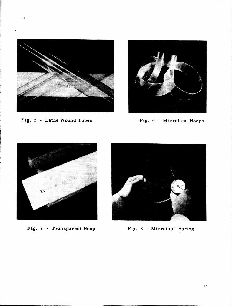
Fig. 5 - Lathe Wound Tubes Fig. 6 - Microtape Hoops
Fig. 7 - Transparent Hoop Fig. 8 - Microtape Spring
b
.
FIGURE 9 - Photomicrograph (50X) Showing Cross Section Through Hollow Rectangular Microtape
FIGURE 10 - Cross Section (50X) Through Hollow Microtape Made F r o m Seven Tubes
FIGURE 11 - Cross Section Through Hoop Wound F r o m Hollow Hexagonal Filament. Layer Against Mandrel.
Note Flats -Down
38

APPENDIX A
Analysis of the Poisson's Ratio Effect on a Thin Composite in a Biaxial Stress Field
by: Richard S. DeBell 6Ab bA
In relating stresses and strains to arrive at a modulus, a tensile analogy is used, and an apparent modulus, Ea, is arrived at by dividing observed strains into the calculated stress:
Ea = d/6, O-tC
61 -J(&2) 6 1 p62 or approx. l0(1 t E2- In the general biaxial case, l1 = lo (1 t r)( 1 -
E - i T 1 (1) hence, E = - 6 1 - P 6 2
A E1 E2 For different materials cooperating in parallel to resist a load applied along the fibers, (sub-r = resin; sub-g = glass; sub-a = apparent)
- - lo7 9,940, 000 = E, = E, circumferential (pg t. 0059 Pg) 1 E, =
1. 00.59
For different materials cooperating in parallel to resist a load applied perpen- dicular to the fibers,
; E, = .74 107 = P. -851 P . . 151 . 85 . 15 - 1 t - Ahg ' 10' 1/3* l o 6 5
7,400,000 = EA = E, axial
Returning to (1). the apparent axial modulus becomes (if 6, = 2 rA)
-56 , 1 106 - - 13, 500,000 = EAa EAa - . 5 & - ,~46~ - 1 - 2 + = 1 - . 6
EA Ec 7.4 9.94 - -
EA E~
39