R VictorTaichung - syncromacchine.com · R VictorTaichung Victor Taichung – an established ISO...
12
R Victor Taichung Victor Taichung – an established ISO 9001 & 14001 company Three milling turrets with Y-axis Twin spindles with built-in motor Turning center with 48 live tools Built-in unmanned automation Q Q Victor Taichung - an established ISO-9001 & 14001 company
-
Upload
duongxuyen -
Category
Documents
-
view
217 -
download
0
Transcript of R VictorTaichung - syncromacchine.com · R VictorTaichung Victor Taichung – an established ISO...

R
VictorTaichung
Victor Taichung – an established ISO 9001 & 14001 company
Three milling turrets with Y-axis
Twin spindles with built-in motor
Turning center with 48 live tools
Built-in unmanned automation
Q Q
Victor Taichung - an established ISO-9001 & 14001 company

● MMinnimmiizzinng tthee cuttttinggg tiimme diiffffereence betweeen OPP-110 aand OPPP--20 to bbbalaancce ccuuttiingg tteemmpoo annd mmaaxximmiziinng thee tuuurninng length oon twwinn-tuurrett laatthess whhhenn deeeeppp hoolee ddrillllingg is reqquiirred..
● OOffferiinng suffficcciienntt 3222 ttooolss ffooor bbooth OP-10 and OOPP-220 mmachhhiniinng aaappplicaatiioonss att qquiicckeerr toool exxcchanngee coompparreed ass multi-taskkiing laathhess witthh AATTC.
● UUseed aass trraveelinnng stteadddy rrestt, wwoorkk rest or tailsstockk foor mmoree fleeexxiblle appppliicattioonns. ● TTurrninngg sslennddeer sshafftts or ddriillllingg/tapping thhe syymmmeetricc hoooles witthh uuppperr tturrrett
ssimmulttaaaneeouuslyy ("bbaalaannnceed ccutttiing""))
Q200T3(M3) - 12x3 tools
Q200T3Y3 – 16x3 tools
Quick Production by Innovative 3rd Turret!
1

Quantitative Production with less floor space
Approx. 30% less!
5680 mm (224") 5570 mm (219") 3320 mm (131")
6760 mm (266")
Vturn-A20YS(2 spindles, 1 turret)
2 x Vturn-A20(YS)(1 spindle, 1 turret)
Vturn-Q200
Vturn-Q200
OP-306'14" (7 tools)
OP-2010'18" (3 tools)
OP-1017'50" (10 tools)
Cycle time 34'34"
Reduced 12'02"
35 % !
Part loading / unloading time
OP-10, 22'32"
OP-20, 6'14"
Cycle time 22'32"130
mm
(5.1
")
110 mm (4.3")
22(1
98.5 mm (5.9")
Ø98
mm
(3.9
")
Cycle time 22'53"
Reduced 11'08"
OP-10, 11'08" (16 tools)
OP-20, 11'27" (6 tools)
Cycle time 11'45"
Part loading / unloading time
Part changeover time
OP-3011'27" (6 tools)
49 % !
OP-106'40" (8 tools)
OP-204'28" (6 tools)
2

● Y-axis (±45mm) on all 3 servo turrets.● 48 tool stations with BMT-55 interface.● High torque at low milling rpm.● Twin built-in spindles.
Q
S1Left spindle
22/25 kW5000 rpm
uurrrettsss.rfaff cee..
ndle5 kWkkrpm
T1BMT-55
16 live tools
T2BMT-55
16 live tools
Quantitative Production by 3 Milling Turrets with Y-axis!
3
BBBMM
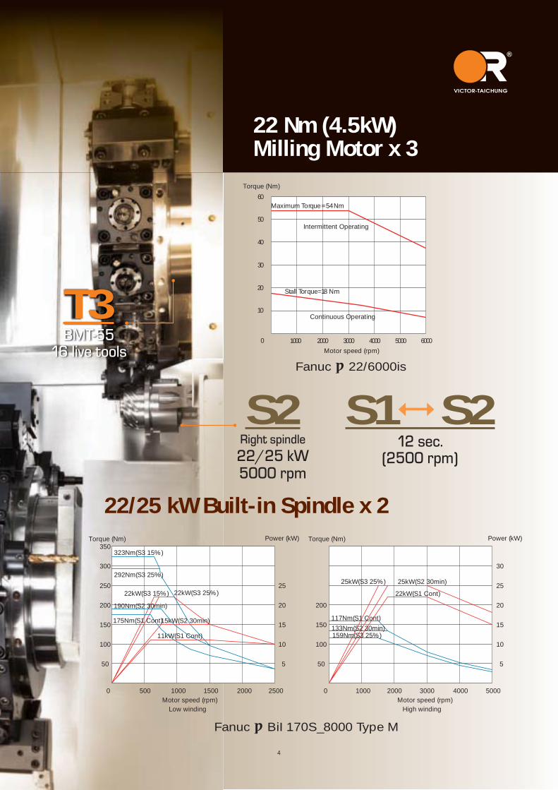
T3BMT-55
16 live tools
S2Right spindle22/25 kW5000 rpm
S1 S212 sec.
(2500 rpm)
Fanuc αBiI 170S_8000 Type M
4
0 500 1000 1500 2000 2500
5
10
15
20
25
100
150
200
250
300
350
50
0 1000 2000 3000 4000 5000
5
10
15
20
25
100
150
200
50
30
Low winding High winding
Power (kW) Power (kW)
Motor speed (rpm)
Torque (Nm) Torque (Nm)
Motor speed (rpm)
11kW(S1 Cont)
15kW(S2 30min)
22kW(S3 25%)22kW(S3 15%) 22kW(S1 Cont)25kW(S2 30min)25kW(S3 25%)
175Nm(S1 Cont)
190Nm(S2 30min)
292Nm(S3 25%)
323Nm(S3 15%)
117Nm(S1 Cont)133Nm(S2 30min)159Nm(S3 25%)
22/25 kW Built-in Spindle x 2
Fanuc α22/6000is
1000 2000 3000 4000
10
20
0Motor speed (rpm)
30
40
50
5000 6000
60Maximum Torque=54Nm
Stall Torque=18 Nm
Torque (Nm)
Intermittent Operating
Continuous Operating
22 Nm (4.5kW) Milling Motor x 3

Tool offset setting & display
Cutting paths on 2 parts in MGI
Energy saving for all peripherals
Machine status in one page
Interactive menu
3 turret system in one screen
Fanuc "air bag" function (DTRQ: Unexpected Disturbance Torque detection) has been integrated into NC package to minimize damages caused by faulty operation. A unique feature is the second monitor (Touch Panel) developed by Victor Taichung which shows additional information regarding the machine status and sample programs ease of operation and maintenance.Cutting Simulation in MGI (3D)
Fanuc 31i-B control with 15" color graphicsWith 15" LCD included as standard, Victor Taichung's Fanuc 31i-B control package displays technical information for the individual turrets in one screen to let the machine operation become an easy job without switching different turret system. The 3D cutting simulation can be executed in MGI (Manual Guide i) and 2D on-line cutting by 3 tools (moving with turret during cutting along the part profile) on BOTH spindles can be done simultaneously.
5
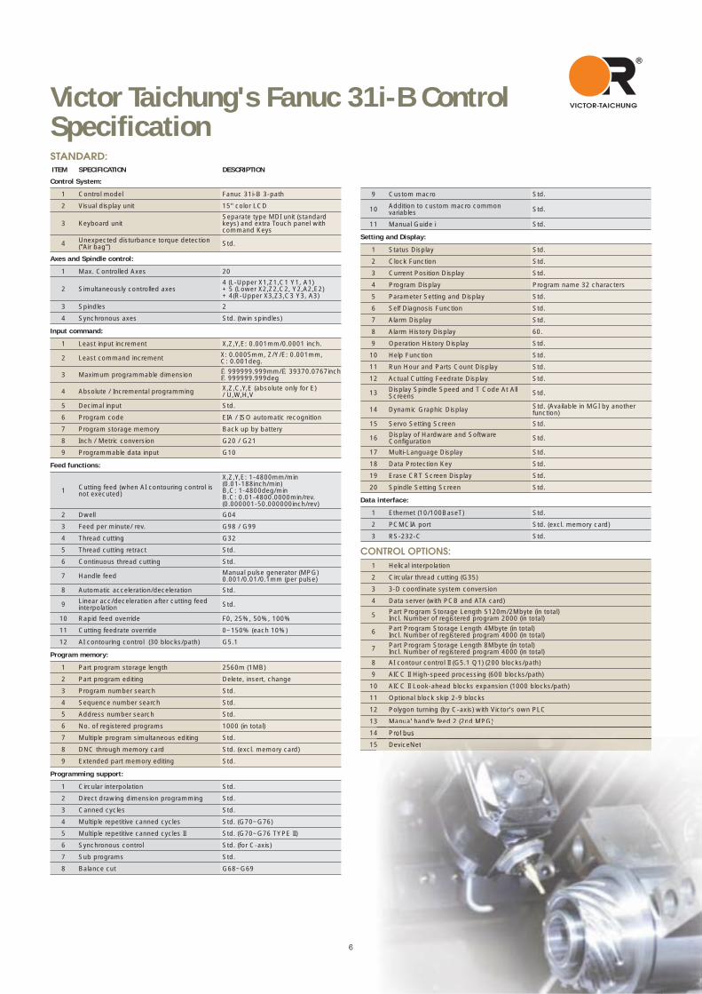
STANDARD:ITEM SPECIFICATION DESCRIPTION Control System:
1 Control model Fanuc 31i-B 3-path
2 Visual display unit 15" color LCD
3 Keyboard unitSeparate type MDI unit (standard keys) and extra Touch panel with command Keys
4 Unexpected disturbance torque detection ("Air bag") Std.
Axes and Spindle control:
1 Max. Controlled Axes 20
2 Simultaneously controlled axes4 (L-Upper X1,Z1,C1 Y1, A1) + 5 (Lower X2,Z2,C2, Y2,A2,E2) + 4(R-Upper X3,Z3,C3 Y3, A3)
3 Spindles 2
4 Synchronous axes Std. (twin spindles)
Input command:
1 Least input increment X,Z,Y,E: 0.001mm/0.0001 inch.
2 Least command increment X: 0.0005mm, Z/Y/E: 0.001mm, C: 0.001deg.
3 Maximum programmable dimension ±999999.999mm/±39370.0767inch±999999.999deg
4 Absolute / Incremental programming X,Z,C,Y,E (absolute only for E)/ U,W,H,V
5 Decimal input Std.
6 Program code EIA / ISO automatic recognition
7 Program storage memory Back up by battery
8 Inch / Metric conversion G20 / G21
9 Programmable data input G10
Feed functions:
1 Cutting feed (when AI contouring control is not executed)
X,Z,Y,E: 1-4800mm/min(0.01-188inch/min)B,C: 1-4800deg/min B.C: 0.01-4800.0000min/rev. (0.000001-50.000000inch/rev)
2 Dwell G04
3 Feed per minute/ rev. G98 / G99
4 Thread cutting G32
5 Thread cutting retract Std.
6 Continuous thread cutting Std.
7 Handle feed Manual pulse generator (MPG) 0.001/0.01/0.1mm (per pulse)
8 Automatic acceleration/deceleration Std.
9 Linear acc/deceleration after cutting feed interpolation Std.
10 Rapid feed override F0, 25%, 50%, 100%
11 Cutting feedrate override 0~150% (each 10%)
12 AI contouring control (30 blocks/path) G5.1
Program memory:
1 Part program storage length 2560m (1MB)
2 Part program editing Delete, insert, change
3 Program number search Std.
4 Sequence number search Std.
5 Address number search Std.
6 No. of registered programs 1000 (in total)
7 Multiple program simultaneous editing Std.
8 DNC through memory card Std. (excl. memory card)
9 Extended part memory editing Std.
Programming support:
1 Circular interpolation Std.
2 Direct drawing dimension programming Std.
3 Canned cycles Std.
4 Multiple repetitive canned cycles Std. (G70~G76)
5 Multiple repetitive canned cycles II Std. (G70~G76 TYPE II)
6 Synchronous control Std. (for C-axis)
7 Sub programs Std.
8 Balance cut G68~G69
Victor Taichung's Fanuc 31i-B Control Specification
6
9 Custom macro Std.
10 Addition to custom macro common variables Std.
11 Manual Guide i Std.
Setting and Display:
1 Status Display Std.
2 Clock Function Std.
3 Current Position Display Std.
4 Program Display Program name 32 characters
5 Parameter Setting and Display Std.
6 Self Diagnosis Function Std.
7 Alarm Display Std.
8 Alarm History Display 60.
9 Operation History Display Std.
10 Help Function Std.
11 Run Hour and Parts Count Display Std.
12 Actual Cutting Feedrate Display Std.
13 Display Spindle Speed and T Code At All Screens Std.
14 Dynamic Graphic Display Std. (Available in MGI by another function)
15 Servo Setting Screen Std.
16 Display of Hardware and Software Configuration Std.
17 Multi-Language Display Std.
18 Data Protection Key Std.
19 Erase CRT Screen Display Std.
20 Spindle Setting Screen Std.
Data interface:
1 Ethernet (10/100BaseT) Std.
2 PCMCIA port Std. (excl. memory card)
3 RS-232-C Std.
CONTROL OPTIONS:1 Helical interpolation
2 Circular thread cutting (G35)
3 3-D coordinate system conversion
4 Data server (with PCB and ATA card)
5 Part Program Storage Length 5120m/2Mbyte (in total)Incl. Number of registered program 2000 (in total)
6 Part Program Storage Length 4Mbyte (in total)Incl. Number of registered program 4000 (in total)
7 Part Program Storage Length 8Mbyte (in total)Incl. Number of registered program 4000 (in total)
8 AI contour control II (G5.1 Q1) (200 blocks/path)
9 AICC II High-speed processing (600 blocks/path)
10 AICC II Look-ahead blocks expansion (1000 blocks/path)
11 Optional block skip 2-9 blocks
12 Polygon turning (by C-axis) with Victor's own PLC
13 Manual handle feed 2 (2nd MPG)
14 Profibus
15 DeviceNet
3 Manual handle feed 2 (2nd MPG)
4 Profibuuss
5 DeevviiceNNet

Powerful hydraulic chuck
● Hydraulic 3-jaw hollow chuck is foot operated for easy and safe operation.
Showa® lubrication pump
● High Quality lube pump (4 liters) ensures long service life for the machine.
Modular Design for Simpler Applications by 2 Turrets
Vturn-Q200TTY2
● with Twin Turrets
Ergonomic design for easy & safe operation
● Enclosed guarding with the high outlet chip conveyor fitted into the machine bed ensures no access to the machine during operation and no coolant leakages.
● Front removed coolant tank with High pressure coolants by Grundfos® pump SPK4-8 improves the machining quality on part surface. Oil skimmer is installed on coolant tank to separate the oil layer from coolants.
● Rotary control box with front mounted hydraulic gauges facilitate the easy adjustment and operation.
● Spindle oil cooler for twin DDS spindles.
Vturn-Q200T2Y2
● with Double Turrets.
Standard Accessories
7

Optional AccessoriesManual Tool Presetter (Renishaw
® Tool-Eye)
The Detachable Renishaw tool presetter allows more space within the machining area, and measures the tool lengths and diameters automatically.
Robotic Part Catcher for Unmanned Operation
By linking the machine to either a bar feeder or work feeding system, a robotic parts catcher then collects the finished part removing it from the machine, for either manual collection or by a part receiver to form an unmanned machining line.
DIN 6499(ER25)
I.D.MT1# O.D.Ø40I.D.MT2# O.D.Ø40 (I.D.MT2# O.D.Ø1-1/2")I.D.MT3# O.D.Ø40 (I.D.MT3# O.D.Ø1-1/2")
I.D.Ø40 (I.D.Ø1-1/2")
I.D.Ø40 (I.D.Ø1-1/2")
I.D.Ø12 (I.D.Ø1/2")I.D.Ø10 (I.D.Ø3/8")I.D.Ø 8 (I.D.Ø5/16")
I.D.Ø32 (I.D.Ø1-1/2")I.D.Ø25 (I.D.Ø1")I.D.Ø20 (I.D.Ø3/4")I.D.Ø16 (I.D.Ø5/8")
I.D.Ø32 (I.D.Ø1-1/4")I.D.Ø25 (I.D.Ø1")I.D.Ø20 (I.D.Ø3/4")
I.D.Ø 6
I.D.Ø16
25 ( 1")
25 ( 1")
I.D.Ø30
Drill
Boring bar
Face & I.D. tool :
Boring bar
U-drill
O.D. tool :
20 ( 3/4")
U-drill holder U-drill socket
Drill socket
Boring bar sleeve
Boring bar sleeveBoring bar/drill holder
20 ( 3/4")
Drill / mill
Face & I.D. tool holder 25 ( 1")
O.D. tool holder 25 ( 1")
20 ( 3/4")O.D. tool holder 25 ( 1")
20 ( 3/4")
20 ( 3/4")
Live tool holder (0°)
Live tool holder (90°)
Live tool holder –dual (90°) Collet
O.D. tool
15
42.5 42.516 19.5
3.5
18.5
39.5
6
32.5 35
Ø42
Ø55
BMT-55 interface
BMT-55 Tool Holders (Optional)
8

5047
47
94
600
103
X2:1
80 [2
05]
X3:1
80 [2
05]
X3:1
80 [2
05]
450
[475
]
450
[475
]45
0 [4
75]
234
156
E:600214
Z2:600
658
232
Z1:230138 Z3:230
106
124
[149
]56
124
[149
]56
5612
4 [1
49]
160180
4545
160180
45
160
180
4545 4545
4545
Machine Layout & Foundation
Machining Range
Q200T3Y3 [T3M3 and T3M0]
1290
660
540
463189
1285
2175
2411
2155
215528
042815
3200 1602
968
(CE)
1106 1573
1602
(CE)
2300
273
900
A A
3200
100
1845
500
50518 745 780 640 50
780
6551
5
500 3265
2155
260
9

60
70
50
40106
10650
Ø208.5
Ø181.3
Ø210.5
Ø184.3
Ø198.3
Ø225.5
Ø201.3
Ø248
Ø40
Ø652Ø580
60
70
40106
220
106
50
Ø208.5
Ø181.3
Ø210.5
Ø184.3
Ø198.3
Ø225.5
Ø201.3
Ø40
Ø652Ø580
294460220
Ø25Ø25
326 X1:180
X2:180 326
56
56
X1-axis travel
X2-axis travel
41
52
34
50
Q200T3 & T2 (without live tools) Q200T3M3 & T2M2
56
326
56
326X2:205
220510
Ø40
Ø32
84
60
2942 2
40
Ø286Ø284.4
Ø286
106
Ø26
8 Ø258
Ø652
Ø580
Ø253.7
Ø250
.6
X1-axis travel
X2-axis travel
326
220
Ø652
Ø50
Ø40Ø40
Ø32
106
70 60
106
2
4016
52
12.5Ø246
Ø286
Ø286
Ø276
Ø250
Ø298
220
50
Ø294
Technical Drawings
50
70
47
600
E:600864
X1:1
80 [2
05]
X3:1
80 [2
05]45
0 [4
75]
450
[475
]
234Z1: 230 Z3: 230
124
[149
]
124
[149
]
56 56
106
138
39
4794
E:600
580 39 103864
Z2:600
X1:1
80 [2
05] 45
0 [4
75]
450
[475
]
X2:1
80 [2
05]
Z1:600
5612
4 [1
49]
124
[149
]56
232
53156
106 70
50 47
Q200T3Y3 & T2Y2
Q200T3(M3) & T2(M2)
10
Q200TTY2 [TTM2 and TT] Q200T2Y2 [T2M2 and T2]
XMTHTL VTL VMC HMC PIM
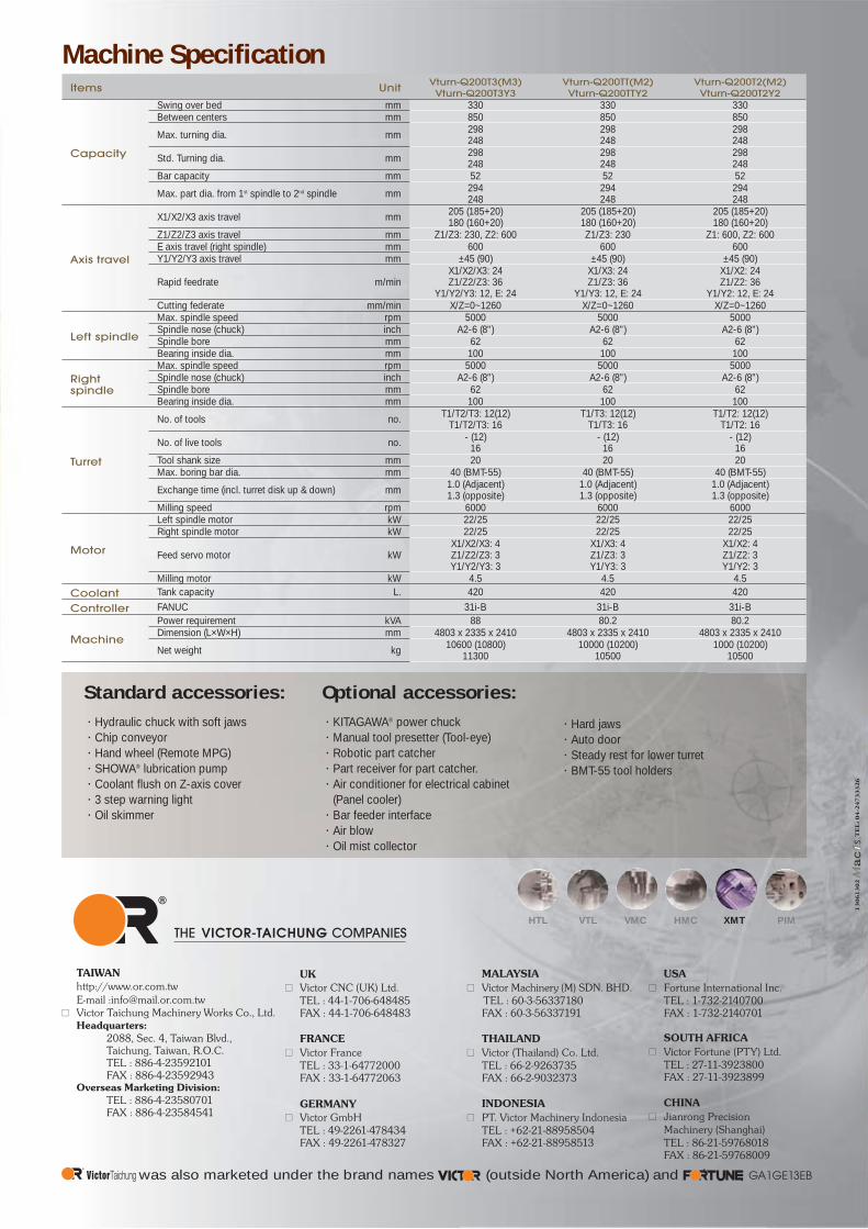
Machine SpecificationItems Unit Vturn-Q200T3(M3)
Vturn-Q200T3Y3Vturn-Q200TT(M2)Vturn-Q200TTY2
Vturn-Q200T2(M2)Vturn-Q200T2Y2
Capacity
Swing over bed mm 330 330 330Between centers mm 850 850 850Max. turning dia. mm 298
248298248
298248
Std. Turning dia. mm 298248
298248
298248
Bar capacity mm 52 52 52Max. part dia. from 1st spindle to 2nd spindle mm 294
248294248
294248
Axis travel
X1/X2/X3 axis travel mm 205 (185+20)180 (160+20)
205 (185+20)180 (160+20)
205 (185+20)180 (160+20)
Z1/Z2/Z3 axis travel mm Z1/Z3: 230, Z2: 600 Z1/Z3: 230 Z1: 600, Z2: 600E axis travel (right spindle) mm 600 600 600Y1/Y2/Y3 axis travel mm ±45 (90) ±45 (90) ±45 (90)
Rapid feedrate m/minX1/X2/X3: 24Z1/Z2/Z3: 36
Y1/Y2/Y3: 12, E: 24
X1/X3: 24Z1/Z3: 36
Y1/Y3: 12, E: 24
X1/X2: 24Z1/Z2: 36
Y1/Y2: 12, E: 24Cutting federate mm/min X/Z=0~1260 X/Z=0~1260 X/Z=0~1260
Left spindle
Max. spindle speed rpm 5000 5000 5000Spindle nose (chuck) inch A2-6 (8") A2-6 (8") A2-6 (8")Spindle bore mm 62 62 62Bearing inside dia. mm 100 100 100
Right spindle
Max. spindle speed rpm 5000 5000 5000Spindle nose (chuck) inch A2-6 (8") A2-6 (8") A2-6 (8")Spindle bore mm 62 62 62Bearing inside dia. mm 100 100 100
Turret
No. of tools no. T1/T2/T3: 12(12)T1/T2/T3: 16
T1/T3: 12(12)T1/T3: 16
T1/T2: 12(12)T1/T2: 16
No. of live tools no. - (12)16
- (12)16
- (12)16
Tool shank size mm 20 20 20Max. boring bar dia. mm 40 (BMT-55) 40 (BMT-55) 40 (BMT-55) Exchange time (incl. turret disk up & down) mm 1.0 (Adjacent)
1.3 (opposite)1.0 (Adjacent)1.3 (opposite)
1.0 (Adjacent)1.3 (opposite)
Milling speed rpm 6000 6000 6000
Motor
Left spindle motor kW 22/25 22/25 22/25 Right spindle motor kW 22/25 22/25 22/25
Feed servo motor kWX1/X2/X3: 4Z1/Z2/Z3: 3Y1/Y2/Y3: 3
X1/X3: 4Z1/Z3: 3Y1/Y3: 3
X1/X2: 4Z1/Z2: 3Y1/Y2: 3
Milling motor kW 4.5 4.5 4.5Coolant Tank capacity L. 420 420 420Controller FANUC 31i-B 31i-B 31i-B
Machine
Power requirement kVA 88 80.2 80.2Dimension (L×W×H) mm 4803 x 2335 x 2410 4803 x 2335 x 2410 4803 x 2335 x 2410Net weight kg 10600 (10800)
1130010000 (10200)
105001000 (10200)
10500
Standard accessories: Hydraulic chuck with soft jawsChip conveyorHand wheel (Remote MPG)SHOWA® lubrication pumpCoolant flush on Z-axis cover3 step warning lightOil skimmer
Optional accessories:KITAGAWA® power chuckManual tool presetter (Tool-eye)Robotic part catcherPart receiver for part catcher.Air conditioner for electrical cabinet (Panel cooler)Bar feeder interfaceAir blowOil mist collector
Hard jawsAuto doorSteady rest for lower turretBMT-55 tool holders
THE COMPANIESVICTOR-TAICHUNG
UK Victor CNC (UK) Ltd.
TEL : 44-1-706-648485 FAX : 44-1-706-648483
FRANCE Victor France
TEL : 33-1-64772000 FAX : 33-1-64772063
GERMANY Victor GmbH
TEL : 49-2261-478434 FAX : 49-2261-478327
MALAYSIAVictor Machinery (M) SDN. BHD.
TEL : 60-3-56337180 FAX : 60-3-56337191
THAILANDVictor (Thailand) Co. Ltd.
TEL : 66-2-9263735 FAX : 66-2-9032373
INDONESIAPT. Victor Machinery Indonesia
TEL : +62-21-88958504 FAX : +62-21-88958513
USAFortune International Inc.
TEL : 1-732-2140700 FAX : 1-732-2140701
SOUTH AFRICAVictor Fortune (PTY) Ltd.
TEL : 27-11-3923800 FAX : 27-11-3923899
CHINAJianrong Precision
Machinery (Shanghai) TEL : 86-21-59768018 FAX : 86-21-59768009
TAIWAN http://www.or.com.tw E-mail :[email protected]
Victor Taichung Machinery Works Co., Ltd. Headquarters: 2088, Sec. 4, Taiwan Blvd., Taichung, Taiwan, R.O.C. TEL : 886-4-23592101 FAX : 886-4-23592943 Overseas Marketing Division: TEL : 886-4-23580701 FAX : 886-4-23584541
GA1GE13EBwas also marketed under the brand names (outside North America) and
13
06
13
02
TE
L: 0
4-2
47
33
32
6