r i A ilLECTIlf 1CS - americanradiohistory.com · SINGLE RANGE OSCILLATOR SUPERHET Part 2 by F. G....
67
A ilLECTIlf 1CS i r i i CONSTRUCTOR MAY 1976 35p www.americanradiohistory.com
Transcript of r i A ilLECTIlf 1CS - americanradiohistory.com · SINGLE RANGE OSCILLATOR SUPERHET Part 2 by F. G....

A ilLECTIlf 1CS i
r i
i
CONSTRUCTOR MAY 1976 35p
www.americanradiohistory.com

Each £3 unit of Home Unit Insurance gives you protection up to the limit shown
This is the simplified insurance you have been waiting for. Not just cover on the contents of your home but a
package of personal protection you and your family need. And it's how we save you so much money: just ONE policy to issue instead of nine! You can build up to the cover you need by additional units
(or # units after the first) up to a maximum of five. So simple. So easy. Apply to your Broker, Agent or local office of a General Accident company. The Home Unit Policy can replace your existing insurances And remember- as you buy more possessions just add more Home Units at any time. Quote Ref. 20/9468
THE GENERAL ACCIDENT FIRE & LIFE ASSURANCE CORPORATION LTD
Metropolitan House, 35 Victoria Avenue, Southend-on-Sea, Essex, SS2 6BT
Itpays to be protected bya
Please send me further particulars of the Home Unit Insurance.
Name
Address
2019468
www.americanradiohistory.com

A SELECT Cs CONSTRUCTOR
MAY 1976
Volume 29 No. 10
Published Monthly (1st of Month) First Published 1947
Incorporating The Radio Amateur
Editorial and Advertising Offices 57 MA/DA VALP LONDON W9 1SN
Telephone 01-286 6141
rü Data Publications Ltd., 1976. Contents may only be reproduced after obtaining prior permission from the Editor. Short abstracts or references are allowable provided acknowledgement of source is given.
Annual Subscription: £5.00 (U.S.A. and Canada $11.00) including postage. Remit- tances should be made payable to "Data Publications Ltd". Overseas readers please pay by cheque or International Money Order.
Technical Queries. We regret that we are unable to answer queries other than those arising from articles appearing in this magazine nor can we advise on modifications to equipment described. We regret that such queries cannot be answered over the telephone; they must be submitted in writing and accompanied by a stamped addressed envelope for reply.
Telegrams Databux, London
Correspondence should be addressed to the Editor, Advertising Manager, Sub- scription Manager or the Publishers as
appropriate.
Opinions expressed by contributors are not necessarily those of the Editor or proprietors.
Production.-Web Offset.
CONTENTS
DUAL METRONOME by P. R. Arthur
SEQUENTIAL RELAY SWITCH by T. Miles
NEWS AND COMMENT
THE 'SUPERALPHADYNE' PORTABLE RECEIVER - Part 1
by Sir Douglas Hall, K.C.M.G.
'ONE-SHOT' ELECTRONIC TIMER (Suggested Circuit 306) by G. A. French
SHORT WAVE NEWS - For DX Listeners by Frank A. Baldwin
'IC PLUS TWO' RECEIVER by A. P. Roberts
AMBIPHONIC ADAPTER Part 2
by R. A. Penfold
NEW PRODUCTS
ADD-ON VU METER by P. R. Arthur
SINGLE RANGE OSCILLATOR SUPERHET Part 2
by F. G. Rayer
IN YOUR WORKSHOP - Readers' Hints
TRADE NOTES
LETTERS - British Amateur Electronics Club; Transistor Lead -out Locater
ELECTRONICS DATA - No. 10 (For The Beginner - Time Constant)
598
602
604
606
612
614
616
622
627
628
632
635
641
641
iii
Published in Great Britain by the Proprietors and Publishers, Data Publications Ltd, 57 Maida Vale, London W9 1SN
The Radio & Electronics Constructor is printed by Swale Press Ltd.
JUNE ISSUE WILL BE
PUBLISHED ON 1st JUNE
585
www.americanradiohistory.com

mv-pAg High quality moduli
OUR PRICE
£19.95 The 450 Tuner provides instant program selection at the touch of a button ensuring accurate tuning of 4 pre -selected stations, any of which may be altered as often as you choose, by simply changing the settings of the pre-set controls. Used with your existing audio equipment or with the BI -KITS STEREO 30 or the MK60 Kit etc. Alternatively the PS12 can be used if no suitable supply is available, together with the Transformer T461. The S450 is supplied fully built, tested and aligned. The unit is easily installed using the simple instructions supplied.
AL 60
25 Watts (RMS)
Max Heat Sink temp 90C. Frequency response 20Hz to 100kHz Distortion better than 0.1 at 1 kHz Supply voltage 15-50v. Thermal Feedback Latest Design Improvements Load - 3, 4, 5 di l6ohms. Signal to noise ratio 80db Overall size 63mm. 105mm. 13mm. Especially designed to a strict specification. Only the finest com- ponents have been used and the latest solid-state circuitry incor- porated in this powerful little amplifier which should satisfy the most critical A.F. enthusiast.
£3.95 Stabilised Power Supply Type SPM80 SPM80 is especially designed to power 2 of the AL60 Amplifiers, up to 15 watts (r.m.s.) per channel simultaneously. With the addi- tion of the Mains Transformer BMT80, the unit will provide out- puts of up to 1.5A at 35V. Size: 63mm. 105mm. 30mm. Incor- porating short circuit protection. Input Voltage: 33-40 V.A.C. Output Voltage: 33V D.C. Nominal Output Current: 10mA-1.5 amps Overlead Current: 1.7 amps approx. Dimensions:
105mm x 63mm x 30mm Transformer BMT80:
£2.60 + 62p postage £3.00
PUSH-BUTTOI
STEREO FM TUNEI Fitted with Phase Lock -loop Decoth * FET Input Stage tr VAR I -CAP diode tuning * Switched AFC * Multi turn pre-sets * LED Stereo Indicator
Typical Specificatiol Sensitivity 39 voli
Stereo separation 30c Supply required 20-30 at 90 Ma max.
STEREO PRE -AMPLIFIER PA 101
br-
A top quality stereo pre -amplifier and tone control unit. The six push- button selector switch provides a choice of inputs together with two really effective filters for high and low frequencies, plus tape output. Frequency response + £dB 20Hz-20KHz Sensitivity of inputs:
1. Tape input 100mV into 100K ohms 2. Radio Tuner 100mV into 100K ohms
3. Magnetic P.U. 3mV into 50K ohms
P.U. Input equalises to R1A. curve within 1 dB from 2011 to 20KHz. Supply - 20 - 35 at 20mA. Dimensions:
299mm x 89mm x 35mr
13.5( P.&P. 49 MK60 AUDIO KIT: Comprising: 2 x AL60. 1 x SPM80. 1 x PA100. 1 front panel and knobs. 1 Kit of parts to include on/off switch, neon in- dicator, stereo headphone sockets plus instruction booklet. COMPLETE PRICE £27.55 plus 62p postage.
TEAK 60 AUDIO KIT: Comprising: Teak veneered cabinet size 16f" x 1 1 ;" x 3;", other parts include aluminium chassis, heatsink and front panel bracket plus back panel and appropriate sockets etc. KIT PRICE £9.20 plus 62p postage.
STEREO 30 COMPLETE AUDI CHASSIS
7+7 WATTS R.M.S. The Stereo 30 comprises a complete stereo pre -amplifier, power amplifiers and power supply. This, with only the addition of a transformer or overwind will produce a high quality audio unit suitable for use with a wide range of inputs i.e. high quality ceramic pick-up, stereo tuner, stereo tape deck, etc. Simple to install, capable of producing really first class results, this unit is supplied with full instructions, black front panel, knobs, mains switch, fuse and fuse holder and universal mounting brackets enabling it to be installed in a record plinth, cabinets of your own con- struction or the cabinet available. Ideal for the beginner or the advanced constructor who requires Hi-Fi performance with a minimum of installa- tion difficulty (can be installed in 30 minutes)
TRANSFORMER £2.45 plus 62p p&p
TEAK CASE £3.65 plus 62p p&p 15.75 p. & p. 45p
586 RADIO & ELECTRONICS CONSTRUCTOR
www.americanradiohistory.com

or stereo, mono and other audio equipment
IT'S NEW! MPA 30
IT'S POWERFUL IT'S THE AL 250 125 watts R.M.S.
POWER AMPLIFIER
Specially designed for use in: Disco Units, P.A. Systems, high power Hi-Fi, Sound
reinforcement systems. The module has a sensitivity of 450mV and a frequency response extending from 25Hz to 20KHz whilst distortion levels are typically below 1%. The use of 4, 1 15w tran- sistors in the output stage makes the unit extremely rugged while damage resulting from incorrect or short-circuit loads is prevented by a 4 transistor protection circuit. SPECIFICATION: Output Power 125watt R.M.S. Continuous. Operating voltage 50-80. Loads 4-16ohms. Frequency response 25Hz- 20kHz Measured at 100 watts. Sensitivity for 100watts output at 1kHz. 450mV. Input impedance 33kohms.
Total harmonic distortion 50 watts into 4ohms, 0.1%. 50 watts into 8ohms, 0.06%. S/N radio better than 80dBs. Damping factor, 8ohms, 65. Semiconductor complement, 13 transistors, 5 diodes. Overall size: Heatsink width 190mm, Length 205mm, Height 40mm.
ONLY £15.95+8% VAT
Enjoy the quality of a magnetic cartridge with your existing ceramic equipment using the new Bi -Pak M.P.A. 30 which is a high quality pre- amplifier enabling magnetic cartridges to be used where facilities exist for the use of ceramic cartridges only. Used in conjunction are 4 low noise, high gain silicon transistors. It is provided with 'a standard DIN input socket for ease of connection. Supplied with full, easy -to -follow instructions.
VAT ADD
12'/2%
POSTAGE & PACKING Postage and Packing add 25p unless otherwise shown. Add extra airmail minimum £1.00
AL10-20-30 AUDIO AMPLIFIER MODULES
The AL10, AL20 and AL30 units are similar in their appearance and in their general specification. However, careful selection of the plastic power devices has resulted in a
range of output powers from 3 to 10 watts R.M.S. The versatility of their design makes them- ideal for use in record players, tape recorders, stereo amplifiers and cassette and cartridge tape players in the home. Harmonic Distortion Po=3 watts f- 1 KHz 0,25% Load Impedance 8-16ohm. Frequency response ± 3dB Po=2 watts 50Hz-25KHz Sensitivity for Rated 0/P - Vs=25V. RL=8ohm 1--1KHz 75mV. RMS. Size: 75mm x 63mm x 25mm
AL10 3w R.M.S. £2.30 AL2O 5w R.M.S. £2.65 AL30 10w R.M.S. £2.95
PA12
£6.50
NEW PA12 Stereo Pre -Amplifier completely redesigned for use with AL10/20/30 Amplifier Modules. Features include on/off volume. Balance. Bass, Treble controls. Complete with tape output. Frequency Response: 20Hz - 20KHz I-3db) Bass and Treble range + 12d13 Input Impedence 1 meg ohm Input Sensitivity 300mV Supply requirements 24V.5mA- Size 152mm x 84mm x 33mm
PS 12 Power supply for AL10/20/30, PA12, S450 etc Input voltage 15 - 20v A.C. Output voltage 22 - 30v D.C. Output Current 800 mA Max. Size 60mm x 43mm x 26mm. Transformer T538 f2.30
£1.20
BI -PAN PO BOX 6, WARE, HERTS.
MAY 1976 - 587
www.americanradiohistory.com

-_
mss. "I MADE IT MYSELF" Imagine the thrill you'll feel ! Imagine how inrpr'essed \ people will be when they're hearing a progr;anlme on a - modern radio you made yourself.
Now! Learn the secrets of radio and electronics by building your
own modern transistor radio! Practical lessons teach you sooner
than you would dream possible. What a wonderful way to learn - and pave the way to a
new, better -paid career! No dreary ploughing through page after page of dull facts and figures. With this fascinating Technatron Course, you learn by building!
You build a modern Transistor Radio . a Burglar Alarm. You learn Radio -and Electronics by doing actual projects you enjoy - making things with your own hands that you'll be proud to own! No wonder it's so fast- and easy to learn this way. Because learning becomes a hobby! And what a profitable hobby. Because opportunities in the field of Radio and Electronics are growing faster than they can find people to fill the jobs!
No soldering - yet you learn faster than you ever dreamed possible. Yes! Faster than you can imagine, you pick up the technical know how you need. Specialty prepared step-by-step lessons show you how to read circuits - assemble compon- ents - build things - experiment. You enjoy every minute of it!
You get everything you need. Tools. Components. Even a versatile Multimeter that we teach you how to use. All included in the course. AT NO EXTRA CHARGE! And this is a course anyone can afford. (You can even*phy for it by easy instalments).
So fast, so easy, this personalised course will teach you even if you don't know a thing today! No matter how little you know now, no matter what your background or education, we'll teach you. Step by step, in simple easy -to -understand mguage, you pick up the secrets
of radio and electronics. You become somebody who makes
things, not just another of the millions, who don't understand. And you could pave the way to a great new career, to add to the' thrill and pride you receive when you look at what you have achieved. Within weeks you could hold in; jour hand your own transistor radio. And after the course you can go on to acquire highpowered technical qualifications, because our famous courses go right up to Cit> & Guilds levels.
Send now for FREE 44 -page book-- see how easy it is - read what others say! Find out more now! This is the gateway to a thrilling new career, or a wonderful hobby you'll enjoy for years. Send the coupon now. There's no obligation.
POST
TODAY FOR
FREE BOOK
To: ALDERMASTON COLLEGE I CRE 1 7 DEPT. CRE 17, READING RG7 4PF
Also at our London Advisory Office. 4 Fore Street Avenue. Moorgate, London, EC2Y 5EJ Tel: 01-628 2721 res, i'a nee to Know mote about your course. riease seno me tree details-plus your big, 76 -page book that tells about all your courses.
NAME
ADDRESS
POSTCODE
'
BIET HOME OF BRITISH INSTITUTE OF ENGINEERING TECHNOLOGY
Bti&( ihoure1f1
Designed by
TEXAS Featured by PRACTICAL WIRELESS
SOLE U.K. DISTRIBUTORS - HENRY'S Build the Texan stereo amplifier, then you can be doubly proud! For a start, you'll own a superb home entertainment unit. And have had all the pleasure of doing it yourself, with the Henry's kit. Look at the Texan specification Incorporating fully integrated stereo preamp and power amp, wuh 61C's, 10 transistors, 6 rectifiers and zener diodes. Plus stabilised, protected circuitry, glass fib pcb; Gardeners low -field low -line mains transformer: all facililles and controls. Slrmdesrgn. chassis 14`", 6" it 2" overall. 20 watts per channel RMS, less than 0.1% distortion alt kHz.
* Can be built Stage by stage Ask for leaflet 20. * Everything necessary supplied Full alter Sales service and guarantees.
KIT PRICE
£32.00 Inc VAT' C1 obi:,
Built and tested
£42.00 inc. VAT +E1.00 p&p.
THE NATURAL FOLLOW-ON -THE TEXAN FM TUNER KIT!
KIT PRICE
£23.50 Inc. VAT+ 60p OEM-
Buildthe matching Texan stereo tuner !Features advanced varicap tuning. Phase lock loop decoder Professionally designed circuit. Everything you need's in the kit. From lnii glass fibre pcb to.the cabinet ilseff. Excellent spec .2.5 uV aeral sensitivity. 500 mV output ladlustable). Tuning range 87-102 MHz. Mains powered. y_ Built and tested £28.50 inc. VAT +p p&p .
VIDEO SPORT . all the electronic excitement
you could wish for! ON ER
An up-to-the-minute game. Plugs 4c
033°° into your own TV aerial Sockel
AOV 900 Switch on. And yo awaY Choose your gameu rfootball, tennis NE
tOEA or hole -in -the -wall Absolutely safe. For you. Your children. And your TV. Mauls powered. List Price £42.50 inc. VAT+
HENRY'S PRICE -ONLY £29.50 50p pelf,.
A
GtFj
WHATEVER YOU DO, DON'T FORGET = YOUR LATEST
HENRY'S CATALOGUE!
I I
ll
-er0
For this new edition, we have made hundreds of changes and additions. It has over 200 pages, containing virtually everything for amateurs and professionals. And you'll have no bother at all finding everything you want, because there's a complete alphabetical index as well as a section index. Together, they put you tight on course for the items you need. From Sinclair projects to educational kits. Oscilloscopes to panel meters. Coils to capacitors. Transistors to valves. Loudspeakers to microphones - all at
competitive prices. Over 200 pages of vital statistics - lust for
YOU! So send now for gout copy. ONLY
50p 20p cary/pack
H '
Over 5000 items inside! Every copy contains
a ?ree SOP voucher,
mMans y new
Over 200 Pages,
FREE to Educational Establishments when ordered on official headed notepaper.
ENRS 09 EDCWAR
SELF-SERVICE D 404 and C ROAD. LONDON
W2 Bargains galore R
- can m and see for g 404/6 EDGWARE ROAD, LONDON W2 01-402 8381 y °'=ryt
LOWER SALES FLOOR, 231.TOTTENHAM CT. RD., LONDON W1 01-636 6681 94/96 UPPER PARLIAMENT STREET, NOTTINGHAM. 0602-40403 ALL MAIL TO HENRYS RADIO. 303 EDGWARE ROAD, LONDON W2
NEW
MIDLANDS STORE
588 RADIO & ELECTRONICS CONSTRUCTOR
www.americanradiohistory.com

RETURN OF POST MAIL ORDER SERVICE NEW BSR HI-FI AUTOCHANGER STEREO AND MONO h
s Plays 12". 10" or 7" records Auto or Manual. A high r ; quality unit backed by BSR ie reliability with 12 months //. // gguarant S izee3ee.+
ACt}m 200/250v
Above motor board 31in //:,;', Below motor board 24in. With STEREO/MONO CARTRIDGE £10.95 Post 75p
PORTABLE PLAYER CABINET f4.50 Modern design. Size 16" x 15" x 7" rexine Post 45p covered. Large front grille. Hinged Lid. Chrome fittings. Motor board cut for Garrard or BSR deck. Few only, in red and black.
HEAVY METAL PLINTHS With P.V.C. Cover. Cut out for most f m.95 B.S.R..or Garrard decks. Silver grey L finish. Size 12+ x 141 x 731n. Size 16 x 131 x 7in. £6.50 Post 76p
TINTED PLASTIC COVERS Sizes: 'A' - 141 -in. x 121in. x 411n., £2.50. 'B' - 2011n. x 121!n. x 41in., £3. 'C' - 1711n. x 1311n. x 34in., £3.25. D' - 1911n. x 141in. x 411n., £3.50. Ideal for record
decks, tape decks, etc. Post 45p.
R.C.S. DISCO (, "
k.
DECK SINGLE RECORD - _.... ! PLAYER
Fitted with auto stop. stereo/compas. cartridge. Base - plate. Size 1 1!n. x 814n. Turntable. Size 7in. diameter. NC mains. 220/250V motor has a separate winding 14 volt t3 power a
plays ll amplifier.siz £6 s95 3 speeds alsm all size records. Post
Two for £13. 45R
COMPLETE STEREO SYSTEM Two full size loudspeakers 131 x 10 x 31in. Player unit clips to loudspeakers making it extremely compact. Overall size only 134 x 10 x 811n. 3 watts per channel,
plays all records 33 rpm 45 rpm. Separate vol- ume & tone controls 240v AC R
Attractive Bargain Price Teak finish Weight 1316s. f25 ß5p carriage
SMITH'S CLOCKWORK 15 AMP TIME SWITCH
0-60 MINUTES Single pole two-way Surface mounting with fixing screws. Will replace existing wall switch to give light for return home, garage, automatic anti -burglar lights etc. Variable knob. Turn on or off at full or intermediate settings. Fully insulated. Makers last list price £4.50. Brand new and fully guaranteed.
OUR PRICE f2.95 Post 35p. Also available 0-6 hours.
CASSETTE RECORDER MOTOR ONLY. 6 Volt. Will replace many types. Ideal for models. £1.25
BLANK ALUMINIUM CHASSIS. 18 s.w.g. 21in. sides 6 x 4in. 70p; 8 x bin. 90pp; 10 x 7in £1.15; 12 x 81n. £1.35; 14 x 9in. £1.50; 16 x 6!n. £1.45; 12 x 3in. 87p; 16 x 10in. £1.70. ALUMINIUM PANELS 18 s.w.g. 6 x 4in. 15p; 8 x bin. 25p; 14 s Bin. 25; 10 x 7in. 30p; 12 x 5in. 30p 12 x Bin. 40p; 16 x bin. 45p; 14 x 9in. 50p; 12 x 12in. 65p; 18 x 10w, 75p ALUMINIUM ANGLE BRACKET bin. long x 1 x 1 25p
14 -inch DIAMETER WAVECHANGE SWITCHES 45p. EA 2 p. 2 -way, or 2 p. 6 -way, or 3 p. 4 -way. 1 p.1 2 -way, or 4 p. 2 -way, or 4 p. 3 -way.
TOGGLE SWITCHES, sp. 20p; dp. 25p dp. dt. 30p.
R.C.S. GENERAL PURPOSE TRANSISTOR PRE -AMPLIFIER BRITISH MADE
Ideal for Mike, Tape P.U., Guitar, etc. Can be used with Battery 9-12v. or H.T. line 200-300V. D.C. operation. Size 14" x 11" x. 1" Response 25 c.o.s. to 25 Kc/s, 26 db gain. For use with valve or transistor equipment. Post Full instructions supplied. Details S.A.E. £1.45 3Op
NEW ELECTROLYTICS
2/350V 20p 250/25V 1Bp 4/350V 20p 500/25V 20p 8/350V 22p1 100+100/275v 65p 16/350V 30p 150+200/275v 70p 32/500V 50p' 8+8/450V 50p 25/25V 10p 8+16/450V 50p 50/50V 10 16+16/450V 50 100/25V 10p. 32+32/350V 50p
16+16+16/275v 45p 50+50/300V 50p 32+32/450V 75p
100+50+50/350V85p 32+32+32/350 75p 900MFD/350V 95p 4700/63V 95p
LOW VOLTAGE ELECTROLYTICS 22, 25, 50, 68, 150, 470, 500, 680, 1500, 2200, 3300, mfd all 6 volt 10p ea. 22, 25, 68, 100, 150, 200, 220, 330, 470, 680, 1000, 1500, 2200, mfd all 10 volt 10p ea. 220, 330, 1000, 4700, mfd all 4v. lOs ea. 1, 2. 4, 5, 8, 16, 25, 30, 50, 100, 200mF 15V 10p. 500mF 12V 15p : 25V 20p ; 5011 30p.
1000mF 12V 20p ; 25V 35p ; 50V 47p ; 100V 700. 2000mF 6V 25p ; 25V 42p ; 50V 57p ; 4700/63V 95p. 2500mF 50V 62p ; 3000mF 25V 47p ; 50V 65p 5000mF 6V 25p ; 12V 42p ; 25V 75p ; 35V 85p ; 50V 95p. 500V-0.001 to 0.05 4p ; 0.1 10p ; 0.25 12p ; 0.47 25p. CERAMIC 1 pF tó0.01 mF, 5p. Silver Mica 2 to 5000pF, 5p. PAPER 350V-0.1 7p; 0.5 18p; ImF or 2mF 150V 15p. MICRO SWITCH single pole changeover 20p. MICRO SWITCH sub min 25p. TWIN GANG. "0-0" 208 F+176pF, £1.50. Slow motion drive 365pFp+365pF with 25pF+25pF, 50p; 500oE standard twin gang 75p. 120 PF twin gang 50p.
ELAC 9 x 5in. Hi -FI SPEAKER, TYPE 59RM. THIS FAMOUS AND WIDELY USED UNIT
11OW AVAILABLE AT BARGAIN PRIC
0 WATT,, 8 OHM. CERAMIC MAGNETS f 3.45 NEON PANE}L INDICATORS, 250V Red or Amber, 30p HIGHp. 10 to 10M.
S%RSISTORS,A Preferred values 101ohms ohms t0 g oto 66 e., 10p.
., 4p. WIRE -WOUND RESISTORS, 5 watt, 10 watt, 15 watt, 10 ohms to 100K, 12p each; 2w 0.5 ohm to 8.2 ohms 15p. TAPE OSCILLATOR COIL. Valve type 35p. FERRITE ROD 8" x 1" 20p; 6 x 20p: 3 x 1" 10p.
MAINS TRANSFORMERS 5öó °cn 250-0-25OV 80mA. 6.3, 2A ' £2.95 250-0-250 80mA. 6.3v 3.5a, 6.3v la or 5v 2a £4.60 350-0-350 80mA. 6.3v 3.5a, 6.3v la or 5v 2a. £5.80 300-0-300 120mA. 6.3v 4a C.T.: 6-3v 2a £7.00 MIDGET 220v 45mA. 6.3v 2a. 21 x 24 x tin. £1.40 HEATER TRANS. 6.3v 3 amps. £1.45 }amp. 95p GENERAL PURPOSE LOW VOLTAGE. Tapped outputs at 2 amp 3, 4, 5, 30v 1 amp 6, B. 10, 12,
6,
16,
8, 9, 10, 12, 15, 18, 24 and £4.60
18, 20, 24, 30, 36, 40, 48, 60 £4.60
2a, 6, 8, 12, 12, 16, 18, 20, 24, 30, 36, 40, 48, 60 £7.00 3a, 6, 8, 10, 12, 16, 18, 20, 24, 30, 36, 40, 48, 60 £8.70 5a, 6, 8, 10, 12, 16, 18, 20, 24, 30, 36, 40, 48,60 £1125 5. 8, 10, 18v 1a £2. 6-0-6v 500mA £1. 9v la £1 12v 300mA £1. 12e 50OmA £1. 12v 750mA £1. 40v 2a tapped 10v or 30v £2.50. 20v 3a £2. 40v 3a £2.50. 22-0-22v 4e D.C. £3.45. AUTO TRANSFORMERS. 115v to 230v or 230v to 115v 150w £5; 250w £6' 400w £7; 500w £8. CHARGER TRANSFORMERS. Input 200/250v for 6 or 12v 14a £2.75 4a £4.60. FULL WAVE BRIDGE CHARGER RECTIFIERS: 6 or 12v outputs 1+a 40p; 2a 55p; 4a 85p.
R.C.S. STABILISED POWER PACK KIT All parts including printed circuit and instructions to build this unit. Voltages available: 6v, 7.5e, 9v, 12v. Up to 100mA output. Post Please state voltage required. f 2.95 45p
R.C.S. 3 WAY CROSSOVER Complete with 12ft twin lead fitted with din speaker plug. Ready assembled with leads for speakers, bass, mid and tweeter. Crossover frequencies -950 cps and 3,000 cps. For systems up to 25 watts. £2.20
VOLUME CONTROLS
5K ohms to 2 Meg. LOG or LIN. L/S 20p. D.P. 35p STEREO L/S 55p. D.P. 75p Edge 5K. S.P. Transistor 25p
80 Ohm Coax 9p yd.
AERAXIAL-AIR SPACED 40yyd £3; 60yd £4.50. FRI er Ideal 625 and cNE
LOW olour. I p yd
Wirewound controls 1lin diam. 3 watts. 10 ohms to 100K British made with long spindles tin. dia 85p ea. DUAL CONCENTRIC POT 500k LOG + 500k LIN D.P. switch. Inner spindle 311e; outer spindle 24in. 75p.
E.M.I. 13f x 8in. SPEAKER SALE I With tweeter q And crossover, 10 f 5.25 watt. State 3 or B ohm Post 45o 15 watt version as illustrated 1.7,faC B or 15 ohm i ..9 ür/
With flared tweeter cone and ceramic magnet, 10 watt 8 ohm. f 3.45 Bass res. 45-60 cps. L Flux 10,000 gauss Post 45p 15 watts single cone model £6.60
Bookshelf Cabinet f6.95 For EMI speakers 16 x 10 x 9in. Teek Veneer Post 75p
R.C.S. 10 WATT AMPLIFIER KIT
RC`3
MWCA1
This kit is suitable for record players, tape play back, guitars, electronic instruments or small PA. systems. Two versions are available. A mono kit or a stereo kit. The mono kit uses 13 semiconductors. The stereo kit uses 22 semiconductors with printed front panel and volume, bass and treble controls. Spec. 10 watts output into 8 ohm, 7 watts into 15 ohms. Response 20 cps to 30K/cs. Input 100 mV high imp. Size 91in x 3in x 2!n.
Mono kit £12.50 Stereo kit £20 45p
LOUDSPEAKERS P.M. 3 ohms, 7 x 4in. £1.25; Bfin. £1.50; 8 x 5in. £1.60; Bin. £1.75' 10 x bin. £1.90; 10in. £2.00. SPECIAL OFFER LOUDSPEAKERS! All Brand New. 3 ohm, 21in; 2jin; 314n; 51n. 8 ohm, 21in; 21in; 5 z 3in; 5in. 15 ohm, 3 !n; 51n; 6 x 41n; 5 x 31n; 7 x 4in; 8 x 5in. 25 ohm, 21in; 3in; 5 x 3in. 35 ohm, 31n; 51n, 80 ohm, 21in; 21ín. 120 ohm, 3in.
£1.25 EACH
LOUDSPEAKER VOLUME CONTROL 15 ohm 10 watt with lin. long threaded bush for wood panel mounting 75p
RICHARD ALLAN TWIN. CONE LOUDSPEAKERS, 8in. diameter 4W £2.50; 10in. diameter 5W £2.95; Post 25p. 12in. diameter, 6W £3.50; 3 or 8 or 15 ohm models. SPEAKER COVERING MATERIALS. Samples Large S.A.E. Horn Tweeters 2-16Kc/s. IOW 8 ohm or 16 ohm £3.60. De Luxe Horn Tweeters 2-18 Kc/s, 15W, 8 ohm £4.00 TWO-WAY 3,000 cps CROSS OVERS 3, 8 or 15 ohm £ 1.90 3 -WAY CROSSOVER 850 cps and 3000 cps (25 watt) £2.20
GOODMANS CONE TWEETER 18.000 cps. 25 watts. 8 ohm. Price £3.60
ELECTRO MAGNETIC PENDULUM MECHANISM
1.5v d.c. operation over 250 hrs continuous on SP2 battery, fully adjustable swing and speed. Ideal displays teaching elettro magnetism or for metronome; strobe etc. 95p. Post 20p
WEYRAD TYPE COILS P50/1AC 60p RA2W 85p Twin Gang £1.50 P50/2CC 40p OPT1 65p Printed P50/3CC 40p LFDT4 65p Circuit 85p
'COAXIAL PLUG 10d. PANEL SOCKETS 10p. LINE 18p. OUTLET BOXES, SURFACE MOUNTING 25p. BALANCED TWIN RIBBON FEEDER 300 ohms, 7p ed. JACK SOCKET Std. open -circuit 15p, closed circuit 23p; Chrome Lead Socket 45p. Phono Plugs 10p. Phono Socket 8p. JACK PLUGS Std. Chrome 20p; 3.5mm Chrome 15p. DIN SOCKETS Chassis 3. -pin 10p; 5 -pin 10p; DIN SOCKETS Lead 3 -pin 18p; 5 -pin 15p. DIN PLUGS 3 -pin 18p; 5 -pin 25p. VALVE HOLDERS 5p; CERAMIC 10p; CANS 5p.
R.C.S. 100 WATT VALVE AMPLIFIER CHASSIS
rm .r,ri.i
Professional model. Four inputs, Treble, Bass, Master Volume Controls. Ideal disco, P.A. or groups. 5 speaker outputs, very robust job S.A.E. for details £85 plus £1.50 carr.
NEWR'DISCO TRANSISTORE
100 WAT ' CHASSIS £55 ALL inputs. 4 outputs separate volume treble Carr. £ 1
and bass controls. Ideal disco or slave amplifier chassis.
RADIO COMPONENT SPECIALISTS Minimum post 30p. Access and Barclaycard welcome
Components Lists 10p. Cash price includes VAT
' 337 WHITEHORSE ROAD, CROYDON, SURREY.
Open 9-6 Wed. 9-1 Sat. 9-5 (Closed for lunch 1.15-2.30)
Rail Selhuret. Tel. 01-684 1665
MAY 1976 589
www.americanradiohistory.com

COMPONENTS HOBBYIST- PROFESSIONAL - DOMESTIC - SURPLUS - INDUSTRIAL JUST AFEW OF OUR BARGAINS ARE LISTED BELOW - SEND STAMPED ADDRESSED ENVELOPE FOR A QUOTE ON OTHER REQUIREMENTS. PAY US A VISIT. OVER 90% OF STOCK BELOW QUANTITY WHOLESALE PRICE. RETURN POSTAL SERVICE UNLESS CHEQUE.
Goods sent at customer's risk, unless suficient payment for registration (1st class letter post) or compensation fee (parcel post) included.
JAP 4 gang min. sealed tuning condensers New 25p Ex-eqpt. 2 or 4 gang 15p
VALVE BASES Printed circuit B9A - B7G Chassis B7 - B7G Shrouded chassis B7G - B9A B8A - B9A chassis - B12A tube
2p 4p 6p 6p
Speaker, 6" x 4", 5 ohm, ideal for car radio etc. £1
T03 or T066 Mica Washer 2p 18 volt 4 amp charger,
bridge rectifier 50p GC10/4B £3.00
Telescopic aerial Closed 91", open 38"
TAG STRIP -6 way 3p VHF Radio Tuner Head Fitted right angle TV 9 way 5p Single 1p Takes ECC 85 80p plug, 50p
BOXES - Grey polystyrene 61 x 112 x 31 mm, top secured by 4 self tapping screws 324-p
Clear perspex sliding lid, 46 x 39 x 24mm 10p ABS, ribbed inside 5mm centres for P.C.B., brass corner inserts, screw down lid, 50 x 100 x 25mm orange 48p; 80 x 150 x 50mm black 70p; 109 x 185 x 60mm black £1.04 ALUMINIUM 8" x 6" x 3" 99p 3"x2"xl" 39p 4"x2j-"x2" 45p 10"x41"x3"£1.02 2f" x 5;"x 11"45p 4" x 5a" x 1f"54p 12" x 5" 3 3"$1.20 4"x4"x11" 45p 6"x4"x2" 65p 10" x 7" x 3" £1.22 4" x 2f" x 11" 45p 7"x5"x21" 79p 12"x8"x 3"£1.50
SWITCHES Pole Way Type
4 2 Sub. Min. Slide 18p 6 2 Slide 20p 4 2 Lever Slide 15p 2 2 Slide 12p
1 3 13 amp small rotary 12p 2 2 Locking with 2 to 3 keys
£1.50 2 1 2 Amp 250V A.C. rotary 24p
Wafer Rotary, all types 30p S.P.S.T. 10 amp 240v. white rocker switch with neon. 1" square flush panel fitting 30p S.P.S.T.dot 13 amp, oblong, push -fit, rocker 20p
AUDIO LEADS 5 pin din plug 180° both ends f Mtr., 80p
3 pin din to open end, 1 yd twin screened 35p Phono to Phono plug, Eft. 35p
COMPUTER AND AUDIO BOARDS VARYING PANELS WITH ZENER, GOLD BOND, SILICON, GERMANIUM, LOW AND HIGH POWER TRANSISTORS AND DIODES, HI STAB RESISTORS, CAPACITORS, ELECTROLYTICS, TRIM POTS, POT
CORES, CHOKES ETC. 31b for 85p + 75p post and packing 71b for £1.75 + £1 post and packing
Skeleton Presets 3" Tape Spools 8p Slider, horizontal or verti- 1" Terry Clips 4p cal standard orsubmitt.5p 12 Volt Solenoid 3Op
KNOBS SILVER METAL PUSH ON WITH POINTER, OR
WHITE PLASTIC, GRUB SCREW WITH POINTER AND GOLD CENTRE 8p EACH. 1" DIAM. WITH 11" SKIRT SPUN ALUMINIUM GRUB SCREW FIXING, 30p EACH.
ZM1162A INDICATOR TUBE 0-9 Inline End View. Rectangular Envelope 170V 2'5M/A £1.50
RESISTORS é -â-1 watt 1 p 1 watt 2p Up to 5 watt wire 10p 10 watt wire wound .. 12p 15 watt ., 14p
RESETTABLE COUNTER English Numbering Machines LTD.
MODEL 4436-159-989 6-14 volt, 6 digit, illuminated, fully enclosed. £2.50
Ferric Chloride, Anhydrous mil. spec. 1 l. bag 50p
Semiconductor Data Book 263 pages. Covers 2N21 through to 2N5558 plus some 3N's. Type/connection/ parameter details £1.50 No VAT
POTS Log or Lin carbon 15p Switched 25p Dual Pots 38p Dual Et switch 50p Lin wirewound 25p Slider Pot 25p Dual Slider 35p 1.5m Edgetype 8p
THERMISTORS VA1008, VA1034,1 VA1039, VA1040,
I, ion
VA1055, VA1066, VA1082, VA1100 VA1077, VA1005, VA1026 15p
RELAYS 12 volt S.P.C.0 octal mercury wetted high speed 75p P.O. 3000 type, 1,000 OHM coil, 4 pole c/o
60p Mains or 12v d.p.c.o. heavy duty octal 60p
Boxed GEC KT88 valve .. £2
THE RADIO SHACK 161 ST. JOHNS HILL, BATTERSEA, LONDON S.W.11
Open 10 a.m. till 7 p.m. Monday to Saturday -Also Sunday afternoons
Terms: Payment with order Telephone: 01-223 5016
ELECTROLYTICS MFD/VOLT. Many others in stock 70- 200- 300- Up to 10V 25V 50V 75V 100V 250V 350V MFD
450 - 500V
10 4p 5p 6p 8p 8p 12p 16p 20p 25 4p 5p 6p 8p 8p 15p 18p 20p 50 4p 5p 6p 9p 13p 18p 25p -
100 5p 6p 10p 12p 19p 20p - - 250 9p 10p 11p 17p 28p - 85p £1
500 10p 11p 17p 24p 45p - - - 1000 13p 17p 40p 75p - £1.50 - - 2000 23p 37p 450 As total values are too numerous to list, use this price guide to work out your actual requirements 8/20, 10/20, 12/20 Tubular tantalum 15p each 16-32/275, 32-32/275, 100-100/150, 100- 100/275 50-50/300 .. .. 20p each 50/50-385 30p 12,000/12, 32-32-50/300, 700/200 100-100- 100-150-150/320 . . .. 50p each 20-20-20/350 .. .. 40p each
RS 100 0 100 micro amp null indicator Approx. 2" x f" x f" £1.50
INDICATORS Bulgin D676 red, takes M.E.S. bulb 20p 12 volt or Mains neon, red pushfit 18p R.S. Scale Print, pressure transfer sheet .1 Op
CAPACITOR GUIDE - maximum 500V Up to .01 ceramic 2p. Up to .01 poly 3p. Up to 1000PF silver mica 5p. 1,200PF up to .01
silver mica 10p. .013 up to .25 poly etc. 4p. .27 up to .68 poly etc. 6p Over 500 volt order from above guide and few others listed below. 6p. .1/600:10p..01 /1000, 1/350, 8/20, .1/900, .22/900, 4/16. .25/250 AC (600vDC) .1/1500 40p. 5/150, 9/275AC, 10/150, 15/150, 40/150.
TRIMMERS, 20p each 100PF Ceramic, 30PF Beehive, 12PF PTFE 2500PF 750 volt, 5 x 50pF, 2 x 220pF, 50PF CERAMIC.
CONNECTOR STRIP Belling Lee L1469, 4 way polythene. 3p each
1; glass fuses 250 m/a or 3 amp (box of 121 18p Bulgin, 5mm Jack plug and switched socket (pair) 30p
1" or 1f" or 2" or 1" CAN CLIPS 2p
MAINS DROPPERS 36+-79 ohm 15p 66+66+158 ohm, 66+66+137 ohm 17+14+6 ohm, 266+14+193 ohm 20p 504-40+1k5 ohm 285+575+148+35 ohm 30p 25+35+97+59+30 ohm
51" x 2;" Speaker, ex -equipment 3 ohm 30p 2 Amp Suppression Choke , , 5p
3x24 -x- " l PAXOLINE 2p
4gxfxâ", f .. .. .. 2 for 1p PCV or metal clip on MES bulb Holder ..5p
VALVE RETAINER CLIP, adjustable 2p
OUTPUT TRANSFORMERS Sub -miniature Transistor Type .. 25p Valve type, centre tapped or straight 40p
12 volt 250M/A or 6 volt 1A Transformers £1
Whiteley Stentorian 3 ohm constant impe- dance volume control way belowtrade at8Op
Drive Cord 1 p per yd.
590 RADIO & ELECTRONICS CONSTRUCTOR
www.americanradiohistory.com

SEMICONDUCTORS BSX20/21 .. 13p III Full spec, marked by Mullarc.. etc. Many other types in stock BSY40 .. 28p 1N916 .. .. 6p
AC107 . 12p BC184C/LC 9p BF180/1 /2/3 .. 16p BSY95A 9p 1N4148.. 1.5p AC128.. 5p BC186/7 13p 8F184/5 .. 15p BU105-01 93p BA145/148 .. 11p AC176 .. 9p BC213L/214B 9p BF194/5/6/7 4p CV7042 (0C41 OC44, Crintercel 10p ACY28 . . .. 18p BC261B 10p BF194A/195C/200 10p ASY63) 7p BZY61 . .. 10p AD149 . . 40p BC327/8 10p BF258/262/263 20p GET111 .. 40p BB103/110 Varicap 18p
AD161 /2 matched pr. 69p BC337/8 11p BF336 .. 25p 0C35 .. .. 321p BB113 Triple Varicap37p AF116 .. 12p BC547/558A 7p 6E528 Dual Mosfet 92p 0N222 . . 30p BA182 . .. 18p AF124/6/7 20p BC548/557 9p BFW10/11 F.E.T. 26p TIP30 .. 43p 0A5/7/10 10p AF1 3 9/1 78/1 8 0/ 1 8 1 30p BC548/A/557/559 9p BFW30 .. £1.35 TIP3055 50p BZY88 Up to 33 volt 6p AF239 .. .. 20p BCX32/36 .. 12p BFW57/58 .. 20p TIS88A FET 23p BZX61 11 volt .. 16p ASY27/73 25p BCY40 . . . . 60p BFX12 . . 20p ZTX300 .. 5p BR100 Diac. .. 19p BC107A or B . . 9p BCY70/1/2 .. 9p BFX29/30/84/88 16p ZTX341 .. 15p
INTEGRATED CIRCUITS TAA700 £2.95 723 reg. 45p 741 8 pin d.i.I. op. Amp 18p TAD100 AMRF £1.00 CA3001 R. F. Amp 50p
BC107/8/9 6p BC108A/B/109B/C 10p BC147/8/9 .. 6p BC147A/B .. 8p BC148A/B/C, 9B/C/S 8p BC157/8/9 6p
BD112/3/5/6 . 40p BD 131/2/3/5/7/9 30p
BD201Z2/3/4 .. £1.00 BD232/4/5 .. 46p BDX77 .. £1.40
BFX89.. .. 35p BFY50/1/2 12p BFY90 .. .. 50p BR101
Programmable BRY39 Uni Junction 31 p BRY56 34p
2N393/M A393.. 30p 2N706 .. .. 6p 2N929 .. .. 14p 2N987 .. .. 36p 2N1507/2219 .. 14p 2N2401/2412/2483 25p
BC158A/B 11p BF115 . .. 10p BSV64 40p 2N2904/5/6/7 .. 10p TAA300 1 wt Amp £1.25 BC159B/C,157A 11p BF167/173 .. 10p BSV79/80 F.E.T.s £1 2N2907A .. 13p NE555v Timer 40p
BC178A/B/179B 10p 6E17819 .. 20p BSV81 Mostet .. 90p 2N3053 .. 13p TAA550 Y or G 31p 2N3054/3055(or equiv) 35p 2N3133 .. 18p 2N3704 .. 9p 2N4037 .. 35p 2N5036 . 60p 2SA141/2/360 .. 31p
TAA263 Amp 62p 7400 8p 7402/4/10/20/30 10p 7414 45p 7438/74/86 25p 7483 80p
BRIDGE RECTIFIERS Amp Volt
1,600 BYX10 30p 1 140 OSH01-200 20p 1.4 42 BY164 28p
Amp Volt
0.6 110 EC433 15p 5 400 Texas 75p
RECTIFIERS OPTO ELECTRONICS 2SB135/6/457.. 20p LM300, 2-20 volt 50p Amp Volt BPX40 65p Photo transistor 40250 .. 60p 74154 67p
IN4004 1 400 IN4005 1 6001
3p BPX42 £1.00 BPY10 £1.00
BPX29 £1.00 OCP71 30p Amp Volt THYRISTORS
IN4006 1 800} IN4007 1 1.000 JJ
4p (VOLTIAC) BIG L.E.D. 0.2"
2v 50m/A max. 1 240 BTX18-200 .. 23p 1 400 BTX18-300 .. 25p
BY103 1 1,500 15p B P Y6ß RED 13p 1 240 BTX30-200 .. 23p SR100 1.5 100 7p SR400 1.5 400 8p REC53A 1.5 1,250 14p
BPY69 £1.00 BPY77
Diodes
ORANGE GREEN 15p YELLOW
15 500 BT107 .. £1.00 6.5 500 BT101-500R 90p 6.5 500 BT109-500R .. 75p
LT102 2 30 10p BYX38-600 2.5 600 40p BYX38-300R 2.5 300 36p BYX38-900 2.5 900 45p
CLIP 2p 20 600 BTW92-600RM £3.00 15 800 BTX95-800R Pulse Modulated £8.00 30 1000 28T10 (Less Nut) £3.00
PHOTO SILICON CONTROLLED SWITCH BPX66 PNPN 10 amp £1.00
BYX38-1200 2.5 1,200 50p .3" red 7 segment L.E.D. 14 PAPER BLOCK CONDENSER Multitore Solder BYX49-600 2.5 600 34p D.I.L. 0-9 + D.P. display 1.9v, 0.25MFD 800 volt 30p 18SWG 3p per foot BYX49-300 2.5 300 26p 10m/a segment, common 1MFD 250 volt 15p
ENAM. COPPER WIRE BYX49-900 2.5 900 40p 65p. 2MFD 250 volt 20p BYX49-1200 2.5 1,200 52p COY11 B L.E.D. 1OMFD 500 volt 80p SWG. PER YD. BYX48-300 6 300 40p BYX48-600 6 600 50p BYX,t8-900 6 900 60p BYX48-1200 6 1,200 80p BYX72-150R 10 150 35p
Infra red transmitter £1 One fifth of trade
4M FD 250 volt 20p 20-24 2p I.C. extraction and insertion tool 40p
26-42 1 p
Wire ended glass neons 5p METAL CHASSIS SOCKETS GAR RAR D
GCS23T or GP93/1 BYX72-300R 10 300 45p BYX72-500R 10 500 55p BYX42-300 10 300 30p
Plastic, Transistor or Diode Holder 1 p
Car Aerial Coax 5 or 6 pin 240° din 9p
Crystal Stereo Cart- ridge £1.00
BYX42-600 10 600 65p Transistor or Diode Pad 1 p Speaker din switched HANDLES BYX42-900 10 900 80p H oldersorpads 5Op per100 3.5mm Switched Socket Rigid light blue nylon BYX42-1200 10 1,200 95p BYX46-300 15 300 £1.00 BYX46-400 15 400 £1.50
64" with secret fitting screws 5p Philips Iron Thermostat 15p
Bulgin 2 -pin flat plug and socket 10p 8 way Cinch standard 0.15 pitch edge socket
BYX46-500 15 500 £1.75 McMurdo PP108 8 way edge plug 10p 20p Belling Lee white BYX46-600 15 600 £2.00 BYX20-200 25 200 60p BYX52-300 40 300 £1.75
T03 HEATSINK Europlec HP1 TO3B individual 'curly' power transistor type. Ready drilled 20p
plastic surface coax outlet box 30p
U.E.C.L. 10 way pin connector 266000
BYX52-1200 40 1,200 £2.50 'Avalanche type
0A1 P10 . 10p Miniature Axial Lead Ferrite Choke formers Tested unmarked, or marked
ample lead ex new equipment U.E.C.L. 20 way pin
Amp Volt TRIACS ACY17-20 8p 0071/2 5p connector 2p 6 800 Plastic RCA 90p ASZ20 8p OC200-5 10p 2A60000A1P20 20p
RS 10 Turn Pot 1% U.E.C.L. 10 way pin socket 26606001 R10
10p
25 900 BTX94-900 £4.00 25 1200 BTX94-1200 £6.00
ASZ21 15p BC186 11p BCY30-34 10p
TIC44 24p 2G240 2-50 2G302 6p
250, 500 Q; 1, 50, 100K £1.50
12-0-12 50M/A Min. Txfmr. 90p Copper coated board BCY70/1/2 8p 2G401 10p
RS 2mrn Terminals F31ue f/ Black . 5 for 40p
U.E.C.L. 20 way pin socketB260800A1 R20
BF115 10p BY127 7p
2N711 25p 2N2926 7p
10" x 9" approx. 32p
Chrome Car Radio facia .. 15p TIE CLIPS BZY88 series 5p 2N598/9 6p 20p Rubber Car Radio gasket .. 5p HG1005 2p
HG5009 2p HG 5079 2p L78/9 2p M3 10p
2N1091 8p 2N1302 8p 2N1907 2-50 Germ. diode 1 p GET120 (AC128
Nylon self locking 7" or 31" 2p 3.5mm STEREO PLUG
Metal screened 35p DLI Pal Delayline .. .. 50p
Relay socket 10p Take miniature 2PC.0 relay
Philips electronic eng- ineer kits add on series
Geared Knob 8-1 ratio 11,-" diam,
B7G or B9A valve can .. 2p 0A81 2p in 1"sq. heat sink) E1004 £1.00 each black 60p 0A47 2p OA200-2 3p OC23 20p
20p GET872 12p 2S3230 30p
0-30, or 0-15, black pvc, 360° dial, silver digits, self adhesive, 41" dia. 10p
RS Yellow Wander Plug Box of 12, 25p
116 Mixed nuts, bolts, washers etc. 35p
SMALL ORDERS, ENCLOSE SUITABLE STAMPED ADDRESSED -ENVELOPE
LARGE ORDERS, ADD SUFFICIENT FOR POSTAGE, INSURANCE, ETC.
TOTAL GOODS PLUS CARRIAGE. ADD V.A.T.
MAIL ORDER CUSTOMERS ONLY ADD 8% VAT -I PAY BALANCE ON 12+% ITEMS ALL ENQUIRIES, ETC., MUST BE ACCOMPANIED BY A
STAMPED ADDRESSED ENVELOPE
MAY 1976 591
www.americanradiohistory.com

r
Videomaster urge all good electronics
enthusiasts to play the game The best thing about the Videomaster
Home T.V. Game Mk. Ill is that the sheer pleasure of building it is immediately followed by the excitement of playing three fascinating games.
The famous Videomaster is now available for you to make. It plugs into any standard UHF 625 line TV set, and it shouldn't take you longer than a few hours.to build.
POST TODAY TO:
V'icleomoster Ltd
In detail ... The Videomaster Mk. Ill has eleven integrated circuits ... four transistors eleven diodes ... is easy to build ... with no alignment necessary because with ready -built and tested transistorized UHF modulator, is complete with.all parts ... including fully drilled and prepared p.c.b.... handsome plastic box ... control leads ... complete step by step assembly instructions ... Runs on a PP7 9 volt battery ... and has logic and analogue "state of the art" circuitry all with National Semiconductors
.CMOS
devices ... with full specification.
The cost? Only £19.95 (+ VAT)
14-20 Headfort Place, London SW1X 7HN Please send me (insert no.) Videomaster Mk. Ill kits at £21.55 ea. inc. VAT. P & P
[enclose my cheque/money order for £ Tick if VHF Modulator required {_i] -£1 extra
NAME
ADDRESS
LALLOW 14 DAYS FOR DELIVERY RegNo1115532 MIMI, mu»
R E/2
592 RADIO & ELECTRONICS CONSTRUCTOR
www.americanradiohistory.com

FROM BIPRE-PAKT
Stirlìne Sound products THANKS TO DEMAND AND STEPPED -UP PRODUCTION THIS HIGH-FIDELITY POWER AMPLIFIER MODULE
SS.1 25 MT -us £5.20 INCLUDING POSTAGE. V.A.T. EXTRA
OUTPUT: 25 watts R.M.S. into 8 SÉ using 50V
DISTORTION: Less than 0.0 5% at all power levels (from 10Hz to 10KHz)
FREQUENCY RESPONSE: ± 1dB 1 5Hz to 30KHz (4 0 I
± 1dB 10Hz to 30KHz (8 Ç 1
HIGH Z INPUT: 100 Kohms (40dB gain/100xl
INPUT SENSITIVITY: 150mV for 25W.R.M.S. out
SIZE: 4i1 x 3" xi" high
Not only is this Stirling Sound's best audio amplifier yet; it rightfully qualifies as one of the best of its kind yet made available to construc- tors. Intended above all for high-fidelity, the characteristics of the SS.125 are such that it can be used in many other applications where depen- dability is the prime consideration. The SS.125 integrates well with other S.S. units as well as those of other manufacturers. Incorporates new circuitry using a complementary long-tailed pair input and full complementary output circuits to give lab standards of performance.
UNSURPASSED VALUE FOR METICULOUS CONSTRUCTORS
More Stirling Sound Modules With easy to follow instructions F.M. UNITS SS.202 I.F. amp. A metre and/or A.F.C. can be
connected (size 3" x 2") £2.65 SS.203 STEREO DECODER for use
with SS. modules or any good F.M. tuner. A LED beacon may be attached (3" x 2") £3.85
AUDIO MODULES SS.105 5 watt amplifier to run from 12V.
(3f" x 2" x e")
£2.25 SS.110 Similar to SS.105 but more powerful
giving 10W. into 4 ohms (24 volts) £2.75 SS.120 20 watt module when used with 34
volts into 4 £3.00 SS.140 Delivers 40 watts R.M.S. into 4 ohms
using a 45V/2A supply such as our SS.345 the power and quality of this unit are superb - two in bridge formation will give 80 watts R.M.S. into 8ohms. size 4" x 3" x }" £3.75
CONTROL UNITS SS.100 Active tone control, stereo, ± 15dB cut
and boost with suitable network £1.60 SS.101 Pre -amp for ceramic p.u., radio and
tape with passive tone control details £1.60 SS.102 Stereo pre -amp with R.I.A.A. equalisa-
tion, mag. p.u., tape and radio in £2.25 SS.105 TERMS OF BUSINESS: VAT at 121%must be added to total value of order except for items marked or I8%I. when VAT is to be added at 8%. No VAT on overseas orders. POST &
PACKING add 25p for UK orders unless marked otherwise. Minimum mail order acceptable - £1, overseas orders, add £1 for postage. Any difference will be credited or charged. PRICES subject to elteration, without notice. AVAILABILITY. All items available at time of going to press when every ef-
fort is made to ensure correctness of information. V.A.T. now 121% except 8% items marked
Order your Stirling Sound products from
SS.202
SS.140
BI-PRE-PAK LTD Co Reg No 820919
222 224 WEST ROAD.WESTCLIFF ON SEA. ESSEX SSO 90F.
TELEPHONE: SOUTHEND (0702)46344
IF*
5 Stirling Sounds Power Supply Units
SS.125 HIGH-FIDELITY
Power Amp.
£5.20 + 65p V.A.T. Post Paid U.K.'
Size: 5}" x 3" e
12V/1A f3.75* 2 1/8" high
SS 318 18V/tA £4.15* SS 334 34V/2Af5.2O* SS 324 24V/1A f4.60* SS 345 45V/4A £&.25*
Transformers separate from boards on SS 334 - SS 345
(all above are at 8% VAT. P/P add 50p any modal)
The new Super Spark Capacitor Discharge Ignition Unit for your car Even better than the original B -P -P version, thousands of which are in use saving motorists appreciable time and money for petrol. Very easy to instal. The Stirling Sound model in- coporates switch for instance change to conventional ignition; immediate adaption to pos. or neg. earth return; anti -burglar immobilising switch, pre-set control for rev, limitation. There are no exposed parts, the unit, on p.c.b. being housed in strong enclosed metal box. With instructions and leads. Size: 7 5/8 x
4 5/8" x 2 1/8" ex. switches.
Robustly designed units in each of which is a stabilised take-off point to pro- vide for tuner, pre - amp and control stages.
SS 312
BUILT & KIT £7.95 TESTED f 10.50
Please add 50p for P/P
A USEFUL CATALOGUE - FREE Send us a large S.A.E. with 10p stamp and we will send you the latest Bi -Pre -Pack catalogue free by return. Packed with useful lines, it's a real money saver. V.A.T. chargeable at the rate prevailing at time of ordering.
To: STIRLING SOUND (BI-PRE-PAK LTD) 220/224 WEST ROAD, WESTCLIFF-ON-SEA ESSEX SSO 9DF
I I
I
Please send
for which I enclose £ Inc. VAT
NAME
ADDRESS
I I '
I I I
RCSB 1 ` IME alM Ma Ma Mal Ma MAY 1976
593
www.americanradiohistory.com

PETITE LTD
THE ABOVE KIT IS AVAILABLE AS SEPARATES
£ p p&p
Kit Complete as above 30.26 1.00 Mk.11 Drill Stand 3.76 35 Mk.11 Drill Only 8.00 35 Flexible Shaft 5.00 25 Transformer 5.50 62 S.30 Kit (30 tools) 16.00 75 S.10 Kit (10 tools) 12.50 55
(Any Quantity)
Replacement accessories ....40p each 15p Circular Saw Blade Sets (4) £2.40 15p Spare Collets £0.40 15p Spare Chuck & 3 Collets £2.50 15p
ALL ABOVE PRICES INCLUDE V.A.T.
S /A FOR ILLUSTRATED LEAFLET & ORDER FORM
119a High Street
Teddington, Middx.
Tel: 01-977 0878
Have pleasure in introducing their Precision Tools from
France for all types of electronic design and
development, professional or amateur
594 RADIO & ELECTRONICS CONSTRUCTOR
www.americanradiohistory.com

SPEAKERS Baker Group 25, 3, 8 or 15 ohms Baker Group 35, 3, 8 or 15 ohms Baker Group 50/12 8 or 15 ohms Baker Group 50/15 8 or 15 ohms Baker Deluxe 12- 8 or 15 ohms Baker Major 3, 8 or 15 ohms Baker Superb 8 or 15 ohms Baker Regent 12" 8 or 15 ohms Baker Auditorium 12" 8 or 15 ohms Baker Auditorium 15" 8 or 15 ohms
Castle BRS/DD 4/8 ohms Celestion G12M 8 or 15 ohms Celestion G12H 8 or 15 ohms Celestion G 12/50 8 or 15 ohms Celestion G12/50TC 8 or 15 ohms Celestion G15C 8 or 15 ohms Celestion G18C 8 or 15 ohms Celestion HF1300 8 or 15 ohms Celestion HF2000 8 ohms Celestion M141000 8 or 15 ohms Celestion CO3K
Decca London ribbon horn Decca London C0/1000/8 Xover Decca DK30 ribbon horn Decca CO/1/8 Xover (DK30)
WILMSLOW AUDIO THE Firm for speakers!
£ 8.64 £ 10.25 £ 14.00 £ 18.62 £ 12.38 £ 10.69 £ 16.31
£9.00 £ 14.65 £ 19.41
£1 £1 £1 £1 £2 £3
EMI 14 e 9 Bass 8 ohms 14A770 'EMI 8x 5, 10 watt, d/cone, roll surr.
EMI 63" d/cone, roll surr. 8 ohms Elac 59RM109 (15) 59RM114 (8) Elac 61" d/cone, roll surr. 8 ohms Flac 10. 1ORM239 8 ohms Eagle Crossover 3000hz 3, 8 or 15 ohms Eagle FR4 Eagle FR65 Eagle FR8 Eagle FR 10 Eagle HT15 Eagle HT21 Eagle MHT10 Eagle FF28 multicell. horn
Fane Pop 15, 8 or 16 ohms Fane Pop 33T, 8 or 16 ohms Fane Pop 50, 8 or 16 ohms Fane Pop 55, 8 or 16 ohms Fane Pop 60, 8 or 16 ohms Fane Pop 70, 8 or 16 ohms £
Fane Pop 100, 8 or 16 ohms £
Fane Crescendo 12A, 8 or 16 ohms £
Fane Crescendo 128L, 8 or 16 ohms £
Fane Crescendo 15/100A, 8 or 16 ohms £
Fane Crescendo 15/125, 8 or 16 ohms £
£28.80 £6.75
£17.25 £4.50
£11.92 £3.56 £3.93 £3.38 £3.83 £3.83 £1.75 £5.51 £8.66
£11.08 £ 14.06
£3.96 £6.13 £4.00 £8.10
£5.25 £8.75
£ 12.50 £ 15.50 £17.95
18.75 27.95 37.95 39.95 49.95 57.95
SPEAKERS Fane Crescendo 18, 8 or 16 ohms Fane 910 Mk.11 horn Fane 920 Mk.11 horn Fane HPX1 crossover 200 watt Fane 13 x8, 15 watt dual cone Fane 8011 8" d/c, roll surr. Goodmans Axent 100 Goodmans Audiom 200 8 ohms Goodmans Axiom 402 8 or 15 ohms Goodmans Twinaxiom 8, 8 or 15 ohms Goodmans Twinaxiom 10, 8 or 15 ohms
2.95 Goodmans 8P 8 or 15 ohms
5.95 Gnodmans 1OP 8 or 15 ohms
6.50 Goodmans 12P 8 or 15 ohms
8.00 Goodmans 12PG 8 or 15 ohms
6.95 Goodmans 12PD 8 or 15 ohms
6.95 Goodmans 12AX 8 or 15 ohms
£6.98 Goodmans 15AX 8 or 15 ohms
£8.55 Goodmans 15P 8 or 15 ohms
13.50 Goodmans 18P 8 or 15 ohms
£4.46 G9)dmans Hifax 750P Goodmans 5" midrange 8 ohms Gauss 12" 200 watt Gauss 15" 200 watt Gauss 18" 200 watt Jordan Watts Module, 4, 8 or 15 ohms
Kef T27 Kef T15 Kef B110 Kef 8200 Kef 8139 Kef DNS Kef DN12 Kef DN13 SP1015 or SP1017 Lowther PM6 Lowther PM6 Mk.l Lowther PM7 Peerless KO1ODT 4 or 8 ohms
Peerless DT1OHFC 8 ohms Peerless K040MRF 8 ohms Peerless MT225HFC 8 ohms Richard Allan CA12 12" bass
Richard Allan HP88 Richard Allan LP8B Richard Allan DT20 Richard Allan CN8280 Richard Allan CN820 Richard Allan Super Disco 60W 12" STC 4001G Tannoy 10" HPD Tannoy 12" HPD Tannoy 15" HPD Wharfedale Super 10 RS/DD 8 ohms
SPEAKER KITS £67.95 Baker Major Module 3, 8 or 15 ohms each £13.28 £15.75 Goodmans DIN 20 4 or 8 ohms each £13.28 £36.95 Goodmans Mezzo Twin kit pair £42.47 £2.50 Helme XLK 20 ir .
£5.50 Helme XLK 30 papair £171050
£8.96 Helme XLK 35 pair £21.60£13.
£7.60 Heine XLK 40 pair £31.50
£13.46 Helme XLK 50 pair £50.40
. KEFkit 1 pair £44.10
£19£9.5080 KEFkit III pair £39.38
£9.86 Peerless 20-2 each £15.70
£5.95 Peerless 30-28 each È21.95
£6.25 Peerless 20-3 each £23.90
£14.95 Peerless 50-4 each £36.45
£16.50 Peerless 1060 pair £50.40
£16.95 Peerless 1070 each £41.40 £38.80 Peerless 1120 each £45.00
£45.00 Richard Allan Twin assembly each £13.46
£22.50 Richard Allan Triple 8 each £20.25
£39.00 Richard Allan Triple 12 each £25.16
£16.00 Richard Allan Super Triple each £29.25 £37.80
£4.05 Richard Allan RA8 Kit pair
£84.00 Richard Allan RA82 Kit pair £59.40
£96.00 Richard Allan RA82L Kit pair 65.70
£129.00Wharfedale Linton II Kit pair £20.81
Wharfedale Glendale 3XP Kit pair £47.70 Wharfedale Dovedale Ill Kit pair £59.40 £ 15.36
£5.18 £6.25 £6.75 £7.85
£ 15.08 £2.08 £5.39 £4.05
£30.60 £32.85 £48.60
£7.25 £8.26 £9.50 £2.95
£ 19.80 £11.93
£8.33 £6.08
£16 £3
£16 £5
£67 £73 £88 £13
COMPLETE KITS IN STOCK FOR
RADFORD STUDIO 90, RADFORD MONITOR 180, RADFORD STUDIO 270, RADFORD STUDIO 360,
HIFI ANSWERS MONITOR (Rogers), HIFI NEW NO
COMPROMOSE (Frisby), WIRELESS WORLD TRANSMISSION LINE (Bailey), PRACTICAL HIFI &
AUDIO MONITOR (Giles), PRACTICAL HIFI & AUDIO TRIANGLE (Giles), POPULAR HIFI (Colloms) ETC.
Construction leaflets for Radford, Kef, Jordan Watts, Tannoy, HiFi. Answers Monitor, Free on request
PA Amplifiers, microphones etc. by Linear, Shure, Eagle, Beyer, AKG etc.
FREE with orders over £10 "Hi-Fi Loudspeaker Enclosures" Book
.20 .15 .95 .90 .50 .75 .15 .50
HI-FI ON DEMONSTRATION
in our showrooms: Akai, Armstrong, Bowers & Wilkins, Castle,
Celestion, Dual, Goodmans, Kef, Leak, Pioneer, Radford, Richard Allan, Rotel, Tandbero, trio,
Videotone, Wharfedale, etc.
-Ask for our HiFi price list - THIS MONTHS SPECIALSI
Pioneer PL12D £43.00, Pioneer PL15R £53.00, Pioneer SX434 £98.95
Rotel RX202 £80.00 Videotone Minimax II £39.00
We stock the complete Radford range of amplifiers, preamplifiers, power amplifiers,
tuners etc., and also Radford Audio Laboratory equipment, low distortion oscillator, distortion
measuring set, audio noise meter etc.
ALL PRICES INCLUDE VAT (Prices correct at 9/4/761
Send stomp for free 32 -page booklet "Choosing a Speaker"
All units guaranteed new and perfect Carriage and Insurance: Speakers 50p each,
12" and up 75p each., Kits 80p each
(£1.60 per pair), Tweeters & crossovers 30p each
WILMSLOW AUDIO
DEPT REC LOUDSPEAKERS, MAIL ORDER AND EXPORT:
SWAN WORKS, BANK SQUARE, WILMSLOW HIFI, RADIO & TV: SWIFT OF WILMSLOW, 5
SWAN STREET, WILMSLOW CHESHIRE
PA, HIFI & ACCESSORIES: WILMSLOW AUDIO, 10 SWAN STREET, WILMSLOW
CHESHIRE TELEPHONE: LOUDSPEAKERS, MAIL ORDER
AND EXPORT WILMSLOW 29599 HIFI, RADIO ETC., WILMSLOW 26213
MAY 1976 595
www.americanradiohistory.com
THE MODERN BOOK CO THE ELECTRONIC MUSIC INSTRUMENTS MANUAL
by Alan Douglas. 6th Edition. Entirely revised. PRICE:
NEWNES CONSTRUCTORS GUIDE ELECTRONIC COMPONENTS by M. A. Colwell PRICE: £2.00 PRINTED CIRCUIT ASSEMBLY by M. J. HUGHES PRICE: £2.00 ELECTRONIC DIAGRAMS by M. A. Colwell PRICE: £2.00 INTRODUCING AMATEUR ELECTRONICS by I. R. Sinclair PRICE: £1.50 DIGITAL ELECTRONIC CIRCUITS & SYSTEMS by N. M. Morris PRICE: £2.60 HOW TO BUILD ELECTRONIC KITS by V. Capel PRICE: £1.95 ELECTRONICS SELF-TAUGHT WITH EXPERIMENTS & PROJECTS by J. Ashe PRICE: £2.35 HANDBOOK OF IC CIRCUIT PROJECTS by J. Ashe PRICE: £2.30 BEGINNER'S GUIDE TO TRANSISTORS by J. A. Reddihough PRICE: £2.25 110 COSMOS DIGITAL IC PROJECTS FOR THE HOME CONSTRUCTOR by R. M. Marston PRICE: £3.00
£8.00 HI-FI CHOICE CASSETTE DECKS by A. McKenzie PRICE: £1.25 SERVICING WITH THE OSCILLOSCOPE by G. J. King PRICE: £4.85 UNDERSTANDING IC OPERATIONAL AMPLIFIERS by R. Melen PRICE: 2.50 TOE COOKBOOK by D. Lancaster PRICE: £5.65 PRINCIPLES OF TRANSISTOR CIRCUITS by S. W. Amos PRICE: £3.65 TRANSISTOR ELECTRONIC ORGANS FOR THE AMATEUR by A. Douglas PRICE: £2.80 RADIO CONSTRUCTION FOR AMATEURS by R. H. Warring PRICE: £2.70 THE RADIO AMATEUR'S HANDBOOK 1976 by A.R.R.L. PRICE: £4.85 RAPID SERVICING OF TRANSISTOR EQUIPMENT by G. J. King PRICE: £2.20 ELECTRONIC SYSTEMS FOR RADIO, T.V. & ELECTRONICS MECHANICS by R. Lewis PRICE: £2.75 AMATEUR RADIO TECHNIQUES by P. Hawker PRICE: £2.43
ALL PRICES INCLUDE POSTAGE We have the Finest Selection of English and American Radio Books in the Country 19-21 PRAED STREET (Dept RC) LONDON W2 INP
Telephone 01-723 4185
I. Understand electronics. Step by step, we take you through all the fundamentals of electronics and show you how easily the sub-
ject can be mastered using our unique Lerna-Kit course.
2. Become a radio amateur. Learn how to become a radio- amateur in contact with the whole world. We give skilled preparation for.the G.P.O. licence.
Build an oscilloscope. Read, draw and understand circuit diagrams.
Carry out over 40 experi- ments on basic electronic circuits and see how they work.
WAA mis riism rinilramlillen No ow III ell all Ng ill Mil am ei mi ow le gmlnö.
Brochure, without obligation to: BRITISH NATIONAL RADIO & ELECTRONICS SCHOOL, P.O. Box 156, Jersey, Channel Islands.
NAME
Dept REX 56.
ADDRESS Block caps please , tir -ri-rira-ri-NBN----titititimi mum mi .11--1.1 1.3 596 RADIO & ELECTRONICS CONSTRUCTOR
www.americanradiohistory.com

As you know, I'm fairly well in with the Managing Director of Home Radio Components Ltd. He was deep in thought when I called on him the other day. "Cooking up something new?" I said. "Yes" he replied "I'm thinking of giving a piece of Vero Board to everybody who buys one of our catalogues, but I'm wondering if the idea is a bit gim- micky." "Certainly not" I assured him "Several electronic magazines have done it before and I'm sure lots of customers appreciate it". Encouraged, he went on "I thought that if I offered 4 projects for which the board could be used it would make it even more useful and in- teresting". That set the ball rolling, and with the co- operation of Vero Electronics Ltd and of Mr. Fred Bennett, Editor of 'Practical Electronics' he is now able to make this
Today's finest Components The price of 99p applies /^+
1 Lal
only to customers in the r 65p plus 34p POST & PACKING,
UK and to BFPO Addresses. ---
unique otter ... to every purchaser of Home Radio Com- ponents Catalogue will be sent a piece of Vero Board and four projects for using it. The offer lasts for' one month from the publication date of this journal. If you have not already got a current Home Radio Components Catalogue here is a
wonderful opportunity to correct the omission (no con- structor should be without one) and at the same time to win a useful piece of material and four interesting projects - a Touch Switch, a Thermometer, a Waa Waa Unit and a
Light Operated Switch: The catalogue costs only 99p (including 34p for packing and postage) and it includes vouchers to the value of 30 pence if used as directed. This is too good to miss - send the coupon below with your. cheque or P.O. for 99 pence. Why delay? Do it today!
L
Please write your Name and Address in block capitals
NAME
ADDRESS
HOME RADIO (Components) LTD., Dept. RC I
234-240 London Road, Mitcham, Surrey CR4 3HD Regd. No. 912966, London J
HOME RADIO 'Components) LTD. Dept. RC, 234-240 London Road, Mitcham, CR4 3H0. Phone: 01-848 8422
MAY 1976 597
www.americanradiohistory.com

QUAL METRONOME
By P. R. Arthur
This electronic metronome employs a very simple circuit and has the unusual feature of providing visual flashes in syn-
chronism with the audible pulses.
Many electronic metronome designs have been published in the amateur electronic magazines over recent years. A number of these circuits are intended to closely imitate the sounds produced by a conven- tional mechanical metronome. Others, however, are designed more along the lines of a straightforward electronic metronome, with various refinements in- cluded to improve their performance.
This metronome circuit falls into the second category and, apart from giving the usual clicking sound, it simultaneously produces a flash from a pan- el light. This duel output has the advantage that, when playing forte passages where the audible metronome beat may be drowned in the sound of the music, the visual indication can still be followed.
A very simple circuit is used, and only a single ac- tive device is employed in the unit. This is the ver- satile and popular 555 integrated circuit timer. The unit is battery powered and will give many hours use from a PP3 9 -volt battery. The current consumption is about 8mA.
The frequency is variable from about 65 to 350 beats per minute.
555 TIMER The 555 i.c. has quite a complicated internal cir-
cuit. It is probably easiest to understand the func- tioning of the device by considering the operation of each stage, and the circuit breaks down into the con- stituent stages shown in Fig. 1. The area inside the broken line represents the 555, whilst the components outside the broken line are those needed to enable the i.c. to operate as a simple astable multivibrator.
When the supply is initially connected, CA begins to charge via RA and RB. TRA is turned off and the output from pin 3 of the device is high. The three resistors in the internal resistor chain of the i.e., RD, RE and RF, are of equal value.
When the voltage across CA becomes fractionally greater than the voltage at the junction of RD and RE, which is two-thirds of the supply voltage, the output of Comparator 1 alters and changes the state of the flip- flop output. TRA turns on and begins to discharge CA via RB until the voltage across CA is less than the voltage at the junction of RE and RF. or one-third of the supply voltage. The output of Comparator 2 then
R
Comparator j6 TRA r
I
31 Output stage C
RF
1
Comparator 2
2
Flip - flop
RA
ÎCA
Fig. 1. Simplified block diagram illustrating the operation of the 555 timer i.c.
598 RADIO & ELECTRONICS CONSTRUCTOR
www.americanradiohistory.com

changes and resets the flip-flop to its original state. TRA is turned off once more, and CA charges through RA and RB until the potential across it again reaches two-thirds of the supply voltage. The whole procedure then repeats itself, and the circuit continues to os- cillate.
Over the period that TRA is turned on the output goes low, with a current being passed by the load, RC.
The time that the output is high is proportional to the time constant of CA and the sum of RA and RB.
COMPONENTS
Resistors (All fixed values ; watt 10% unless otherwise stated)
R1 561 1 watt R2 680 R3 100k c R4 2.7k 11
VR1 470kgZ potentiometer, linear
Capacitors Cl 100pF or 125zF electrolytic, 10V Wkg. C2 2.2jtF plastic foil, type C280 (Mullard)
Integrated Circuit IC1 555
Light -Emitting Diode LED1 TIL209 or equivalent, with mounting bush
Switch S1 s.p.s.t., rotary or toggle (see text)
Speaker LS1 35 to 80e, 2; to 3zin. diameter
Miscellaneous Veroboard, 0.lin. matrix Aluminium box, 51 x 4 x l'in. (see text) Control knob(s), as required 9 volt battery type PP3 (Every Ready) Battery connector
The output is low for a duration proportional to the time constant of CA and RB only. During this period, RA plays no active part as its lower end is held close to the negative supply rail by TRA.
PRACTICAL CIRCUIT The practical metronome circuit is very straight-
forward, and is shown in Fig. 2. The 555 has quite a high output current capability,
and pin 3 of the device is used to drive both the speaker and the light -emitting diode. R1 limits the speaker current to â satisfactory level, and R2 similarly limits the 1.e.d. current.
The charging time of C2 is determined by the values of VR1, R3 and R4. VR1 can be adjusted to alter this time, and it thus acts as a frequency control. The relatively low value of R4 gives a very short dis- charge time for C2. It is while C2 is discharging that current is passed by the l.e.d. and the loudspeaker.
LS1
1=IcI
A LEDI
TIL209
CI'
ICI
555
1
SI
On -Oit l VR1
9V+
A
nTIL 209 Lead-outs
C
Fig. 2. The metronome has the very simple cir- cuit shown here
MAY 1976 599
www.americanradiohistory.com

Veroboard panel having 18 by 19 holes, as illustrated in Fig. 3. As will be explained shortly, there are two ways of mounting this panel, and with one of these there is no necessity to drill the two 6BA clear holes shown in the diagram. First cut out a panel of the required size and then, if these will be needed, drill out the two 6BA clear holes. Next, cut the strips at the points indicated in Fig. 3, using a Vero spot face cutter or a small twist drill. Next, fit and solder the five link wires. These can consist of ordinary tinned copper wire of around 22 s.w.g., and do not need to be insulated. Then, solder on the components. The leads to external components are fitted later.
CASE
The case must be sufficiently large to take the speaker and the Veroboard panel, and that used for the prototype was an aluminium box with front panel type BA4, with nominal dimensions of 51 by 4 by 1 in. This box is available from several retailers, in- cluding Bi -Pak and Henry's Radio. Other boxes of similar dimensions may be used, the main proviso be- ing, of course, that the parts can be accommodated.
Pos. battery clip via S1 LEDI anode and LS1
ABCDE G H JKLMNOPQRS o
A continuous string of audible pulses is thus produced by the speaker, with D1 briefly flashing on at the same time as each pulse. VR1 varies the repeti- tion rate of the pulses and flashes. Cl is the supply decoupling capacitor and S1 is the on -off switch. The loudspeaker may be any small type with a diameter of 21 to 31ín. and an impedance between 35 0 and 800. In general, the higher the speaker im-
pedance the better the results which are given. The l.e.d. is a TIL209 or equivalent, with a mounting bush or panel holder. It passes a current of around 10mA when it is turned on. The on -off switch may be toggle or rotary, with rotary giving a better appearance to the completed unit. The author employed a miniature multi -way rotary switch with adjustable end stop, no connections being made to the unused tags. A small single pole or double pole 2 -way rotary switch could alternatively be used. C2 is a plastic foil non - electrolytic capacitor type C280.
COMPONENT PANEL Apart from Sl, VR1, the l.e.d. and the speaker, the
components are wired up on an O.lin. matrix
6BA clear
LEDI cathode
2
3
4
5
6
7
B
9
10
I
12
13
14
15
16
17
18
R2
o
o
O o o o
o o o
o o o
o
o o 0
o o
O 0
o
o
o
o o
o
o o o o o 0 0 0 0
o o o o o o o o o S o o o o o o o o o o o o
O 0 0 0 0 0 0 0 0
o o 1 o o o o 0 0
o o o
o l o o o 0 0
LSI
O 0 o O 0
0
R3 o 0
o o
o o
o o
o o o o o
o o o 0 o
o o o o
6BA clear
Neg. battery clip
Direction of strips
Cut strips at F -6,F -7,F -B and F-9
Fig. 3. Component layout on the Veroboard panel. Also shown are the connections to components external to the panel
600 RADIO & ELECTRONICS CONSTRUCTOR
www.americanradiohistory.com
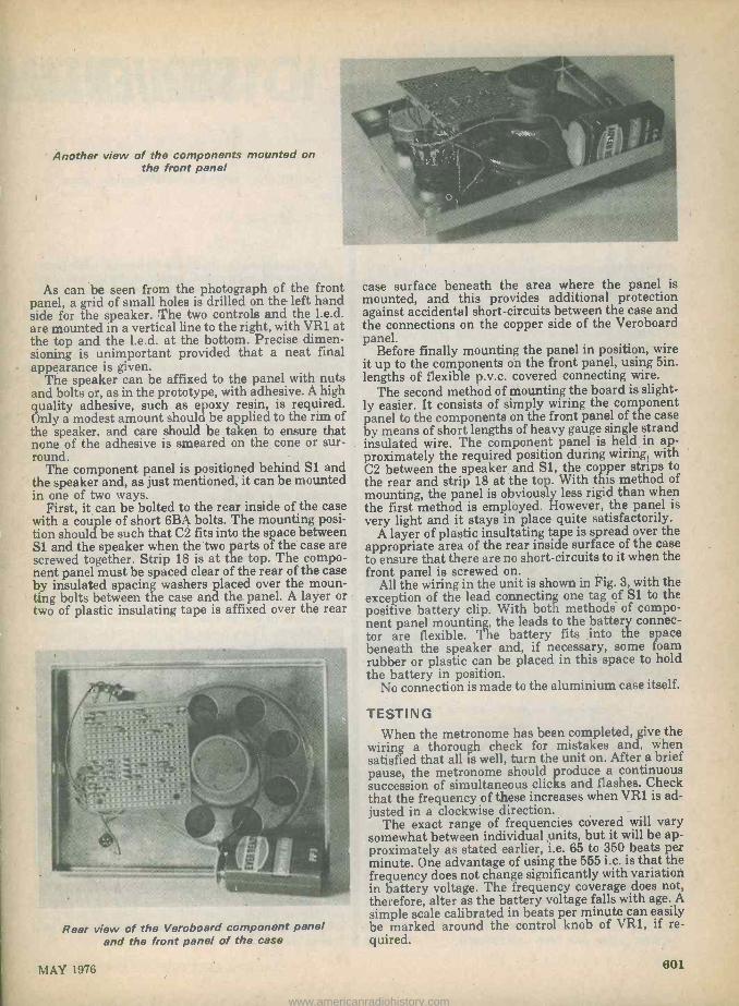
Another view of the components mounted on the front panel
As can be seen from the photograph of the front panel, a grid of small holes is drilled on the left hand side for the speaker. The two controls and the l.e.d. are mounted in a vertical line to the right, with VR1 at the top and the l.e.d. at the bottom. Precise dimen- sioning is unimportant provided that a neat final appearance is given.
The speaker can be affixed to the panel with nuts and bolts or, as in the prototype, with adhesive. A high quality adhesive, such as epoxy resin, is required. Only a modest amount should be applied to the rim of the speaker, and care should be taken to ensure that none of the adhesive is smeared on the cone or sur- round.
The component panel is positioned behind S1 and the speaker and, as just mentioned, it can be mounted in one of two ways.
First, it can be bolted to the rear inside of the case with a couple of short 6BA bolts. The mounting posi- tion should be such that C2 fits into the space between S1 and the speaker when the two parts of the case are screwed together. Strip 18 is at the top. The compo- nent panel must be spaced clear of the rear of the case by insulated spacing washers placed over the moun- ting bolts between the case and the. panel. A layer or two of plastic insulating tape is affixed over the rear
Rear view of the Veroboard component panel and the front panel of the case
° .. . case surface beneath the area where the panel is mounted, and this provides additional protection against accidental short-circuits between the case and the connections on the copper side of the Veroboard panel.
Before finally mounting the panel in position, wire it up to the components on the front panel, using 5in. lengths of flexible p.v.c. covered connecting wire.
The second method of mounting the board is slight- ly easier. It consists of simply wiring the component panel to the components on the front panel of the case by means of short lengths of heavy gauge single strand insulated wire. The component panel is held in ap- proximately the required position during wiring, with C2 between the speaker and Sl, the copper strips to the rear and strip 18 at the top. With this method of mounting, the panel is obviously less rigid than when the first method is employed. However, the panel is very light and it stays in place quite satisfactorily.
A layer of plastic insultating tape is spread over the appropriate area of the rear inside surface of the case to ensure that there are no short-circuits to it when the front panel is screwed on.
All the wiring in the unit is shown in Fig. 3, with the exception of the lead connecting one tag of S1 to the positive battery clip. With both methods of compo- nent panel mounting, the leads to the battery connec- tor are flexible. The battery fits ,into the space beneath the speaker and, if necessary, some foam rubber or plastic can be placed in this space to hold the battery in position.
No connection is made to the aluminium case itself.
TESTING When the metronome has been completed, give the
wiring a thorough check for mistakes and, when satisfied that all is well, turn the unit on. After a brief pause, the metronome should produce a continuous succession of simultaneous clicks and flashes. Check that the frequency of these increases when VR1 is ad- justed in a clockwise direction.
The exact range of frequencies covered will vary somewhat between individual units, but it will be ap- proximately as stated earlier, i.e. 65 to 350 beats per minute. One advantage of using the 555 i.c. is that the frequency does not change significantly with variation in battery voltage. The frequency coverage does not, therefore, alter as the battery voltage falls with age. A
simple scale calibrated in beats per minute can easily be marked around the control knob of VR1, if re- quired.
MAY 1976 601
www.americanradiohistory.com

TONE ALTERATION Metronomes usually produce a fairly high pitched
sound, and it is possible to obtain a slightly more con- ventional and higher pitched pulse from the unit by filtering out some of the bass content. This can be done by connecting an electrolytic capacitor of suitable value in series with the speaker. The modified circuit is shown in Fig. 4.
L51
Additionale capacitor
RI
LEDI
41118
ICI
+9V
Fig. 4. A modification which allows pulses of higher pitch to be produced. The value of the additional capacitor is selected to suit the par-
ticular speaker employed
A close look at the Veroboard panel
If the second method of mountingthe component panel has been used, the capacitor wil simply replace the lead connecting hole B16 on the panel to the ap- propriate speaker tag. The capacitor lead -outs should be covered with sleeving. With the first method of mounting, the loudspeaker lead from B16 can be removed and the capacitor, positioned horizontally, connected between F16 and Fli. The loudspeaker lead can then connect to Eli. The value required in the capacitor depends to some extent on the speaker employed, and is best found by trial and error. It should be a miniature type, have a working voltage of 10 volts and will probably be 501tF or a little less. Too low a value will result in greatly reduced volume. The capacitor is wired permanently into circuit after the required value has been determined.
SEQUENTIA I
By T. Miles
It is occasionally desirable to have a push-button circuit in which an initial touch on the button causes equipment to be switched on, whilst a second touch on the button causes it to turn off again. If the button is pressed once more the equipment is again switched on, and so on.
Sequential operation in this manner can be provid- ed by, say, a JK master -slave flip-flop i.c., but such a device could not be used to control a circuit which operated at a relatively high voltage or current. The flip-flop could, of course, control such a circuit by way of a relay. Whereup, one can argue that, if one relay has to be used, why not employ two relays and dis- pense with the flip-flop!
This article describes a very simple sequential switching circuit which incorporates two standard relays. One of these energises and stays energised when a button is pressed, and it releases and stays released when the button pressed a second
CIRCUIT OPERATION The circuit of the sequential switch appears in Fig.
1. In this diagram the two relays are shown with the `detached' method of presentation. Each relay coil is presented as a rectangle alongside which is an iden- tifying letter over a figure. The figure represents the number of contact sets which the relay has, and these are shown, in the de -energised condition, anywhere in the diagram. Thus, Relay A has two contact sets, these being Al and A2.
Both relays should be of the same type and have the same coil resistance. Those employed by the author were P.0.3000 types with coil resistances of 50011
When the 18 volt supply is initially applied, current flows from the positive rail through the coil of Relay A, the 12 volt zener diode ZD1 and the coil of Relay B to the negative rail. The zener diode drops a voltage of 12 volts whereupon only 3 volts appears across each relay coil. This voltage is not sufficient to operate the relays and they remain in the de -energised state.
If push-button Si is now pressed, the lower end of the coil of Relay A is connected direct to the negative rail via contacts B1, with the result that Relay A energises. Its contact set Al closes. The circuit remains in this state during the period when Si is closed. There is no voltage across the coil of relay B, as this coil is short-circuited by way of 51 and contacts B1.
When S1 is opened, the short-circuit is taken off the coil of Relay B and this energises. Both the relay coils are now in series across the 18 volt supply and both relays are energised. Also, contact set B1 has changed aver to the energised position.
602 RADIO & ELECTRONICS CONSTRUCTOR
www.americanradiohistory.com

ELAY SWITCH
A very simple sequential switching circuit which incorporates two standard relays.
BI
ZDl
BZY88C12V
fia- To
controlled circuit
+I8V
Fig. 1. The circuit of the sequential switch. Relay A successively energises and releases as
the push-button is pressed
If S1 is now pressed again, a short-circuit is placed across the coil of Relay A by way of the energised con- tact set Bi. Relay A releases and its contacts Al open. A circuit is now completed from the positive rail via contact set Bl, S1 and ZDi, causing 6 volts to be pre- sent across the coil of Relay B. This voltage is suf- ficient to maintain the already operated relay in the energised states
Si is next opened whereupon the positive circuit via ZD1 to the coil of Relay B is broken. There is now 3
volts across each relay coil and Relay B releases. The circuit has returned to its initial state and will start another cycle if S1 is pushed once more.
The circuit controlled by the sequential switch is turned on and off by the second set of contacts, A2, of Relay A.
COIL VOLTAGES The relays employed in the circuit energise reliably
at a coil voltage of 9 volts. It will be noted that 18 volts is applied across the coil of Relay A when S1 is initial- ly closed. The use of a voltage which is double the nor- mal energising voltage is quite in order with the relay types employed.
On the second part of the switching cycle, Relay B is held energised at a coil voltage of 6 volts and then releases at a coil voltage of 3 volts. This 2:1 voltage change should be more than adequate for reliable relay release. If ZD1 should be on its lower voltage tolerance, or if Relay B shows a little reluctance to release, one or more forward biased silicon rectifiers may be inserted in series with ZD1, as in Fig. 2. These may be type 1N4002 or similar, and each will drop a further 0.6 volt. The writer had no problems in this respect with the prototype, in which the actual zener voltage, as measured, was approximately 12.2 volts. The 18 volt supply should be reasonably well regulated, to say plus or minus 0.5 volt. Current con- sumption varies between 6mA and 36mA.
Although not checked out by the author, there seems little reason to doubt that the basic circuit of Fig. 1 should not cope satisfactorily with relays of a different type and having different coil resistance. As already mentioned, both relays should be of the same type and have the same coil resistance. Some experi- ment may be needed to find the optimum supply and zener diode voltages.
Al Additional diode or
1+ diodes
ZDl
Fig. 2. If desired, the zener delay voltage may be slightly increased by adding one or
more silicon rectifiers in series
P.0.3000 relays are fairly frequently advertised on the surplus market. They are also available, made up to customer's specification, from L. Wilkinson (Croydon) Ltd., Longley House, Longley Road, West Croydon, Surrey.
MAY 1976 603
www.americanradiohistory.com

NEWS AND TECHNOLOGY BREAKTHROUGH WITH SINGLE CHIP CALCULATOR
A technical breakthrough has been achieved by CBM Commodore Business Machines of 446 Bath Road, Slough, Bucks, with their own "3D" chip. This, for the first time ever in a calculator it is claimed, has all the components including digit drivers built into a single integrated circuit.
This chip is being used to up -grade the very popular 776MD to the 796MD. The new model has 8 digits, a memory and percent key and will retail for only £6.95 including VAT.
Kit Spencer, Marketing Manager CBM, commen- ting on the launch said: "This technical breakthrough by our own design team will help in further es- tablishing our current position of market leadership achieved by our value for money policy with a memory and percent calculator for only £6,95."
RAPID SETTING ADHESIVE FROM KELSEAL
Kelseal Ltd., of Wood Lane End, Hemel Hempstead, Herts., announce the introduction of a range of Rapid Setting Cyanoacrylate Adhesives. Minute quantities can be used for almost instantaneous adhesion to a variety of substrates. Viscosity of the various grades vary making them suitable for application where good spreading or a concentrated amount is required, ac- cording to surface condition.
The standard grades available are: HM22 -A methyl ester of medium viscosity and setting time. Primarily recommended for metals.
HM32 - A methyl ester of high viscosity and medium setting time. Primarily recommended for metals.
HE32 - An ethyl ester of high viscosity and short/ medium setting time. Primarily recommended for plastics.
HB11 -A butyl ester of low viscosity and fast set- ting time. Primarily recommended for rubbers but also plastics.
The adhesive is supplied in three sizes of plastic container, 20g, 45g, and 450g.
Varying applicator nozzles are available to suit the viscosity of the product and application.
804 RADIO & ELECTRONICS CONSTRUCTOR
www.americanradiohistory.com
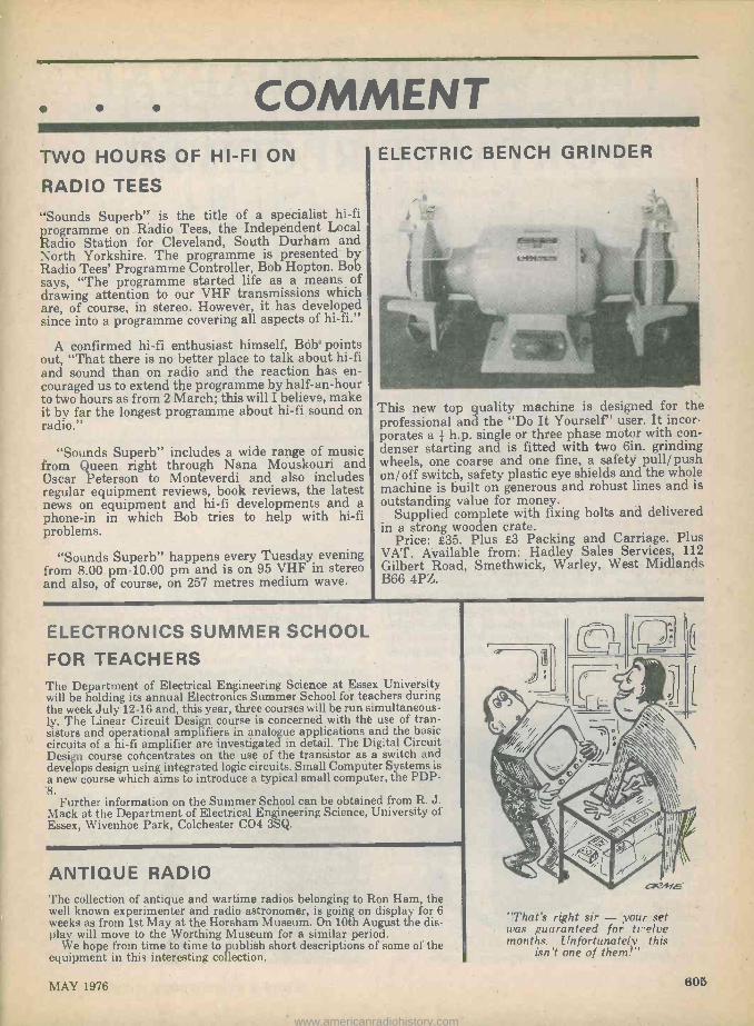
COMMENT TWO HOURS OF HI-FI ON
RADIO TEES
"Sounds Superb" is the title of a specialist hi-fi programme on Radio Tees, the Independent Local Radio Station for Cleveland, South Durham and North Yorkshire. The programme is presented b Radio Tees' Programme Controller, Bob Hopton. Bob says, "The programme started life as a means of drawing attention to our VHF transmissions which are, of course, in stereo. However, it has developed since into a programme covering all aspects of hi-fi."
A confirmed hi-fi enthusiast himself, Bob points out, "That there is no better place to talk about hi-fi and sound than on radio and the reaction has en- couraged us to extend the programme by half -an -hour to two hours as from 2 March; this will I believe, make it by far the longest programme about hi-fi sound on radio."
"Sounds Superb" includes a wide range of music from Queen right through Nana Mouskouri and Oscar Peterson to Monteverdi and also includes regular equipment reviews, book reviews, the latest news on equipment and hi-fi developments and a phone-in in which Bob tries to help with hi-fi problems.
"Sounds Superb" happens every Tuesday evening from 8.00 pm -10.00 pm and is on 95 VHF in stereo and also, of course, on 257 metres medium wave.
ELECTRIC BENCH GRINDER
/,//Dó4%
This new top quality machine is designed for the professional and the "Do It Yourself" user. It incor- porates a i h.p; single or three phase motor with con- denser starting and is fitted with two 6in. grinding wheels, one coarse and one fine, a safety pull/ push on/off switch, safety plastic eye shields and the whole machine is built on generous and robust lines and is outstanding value for money.
Supplied complete with fixing bolts and delivered in a strong wooden crate.
Price: £35. Plus £3 Packing and Carriage. Plus VAT. Available from: Hadley Sales Services, 112 Gilbert Road, Smethwick, Warley, West Midlands B66 4PZ.
ELECTRONICS SUMMER SCHOOL
FOR TEACHERS The Department of Electrical Engineering Science at Essex University will be holding its annual Electronics Summer School for teachers during the week July 12-16 and, this year, three courses will be run simultaneous- ly. The Linear Circuit Design course is concerned with the use of tran- sistors and operational amplifiers in analogue applications and the basic circuits of a hi-fi amplifier are investigated in detail. The Digital Circuit Design course concentrates on the use of the transistor as a switch and develops design using integrated logic circuits. Small Computer Systems is a new course which aims to introduce a typical small computer, the PDP- 8.
Further information on the Summer School can be obtained from R. J. Mack at the Department of Electrical Engineering Science, University of Essex, Wivenhoe Park, Colchester C04 3SQ.
ANTIQUE RADIO 'l'he collection of antique and wartime radios belonging to Ron Ham, the well known experimenter and radio astronomer, is going on display for 6 weeks as from 1st May at the Horsham Museum. On 10th August the dis- play will move to the Worthing Museum for a similar period.
We hope from time to time to publish short descriptions of some of the equipment in this interesting collection.
"That's right sir - your set u'as guaranteed for trelve months. Itnfortunately this
isn't one of them,"
MAY 1976 605
www.americanradiohistory.com

THE SUPERALPHADYNE'
PORTABLE RECEIVER
Part 1
By Sir Douglas Hall, K.C.M.G.
Employing an ingenious reflex circuit, this receiver offers a high level of selectivity on medium and long waves. There are only three transistors, and an added bonus is an extension of range from the lower medium wave band down to 120 metres. The article will be concluded in Part 2, to be published next
month.
Home -constructed radio receivers with single tuned circuits have the great advantages, when compared with superhets, of simplicity and economy of com- ponents, this latter point being of considerable impor- tance in these days of rapidly rising prices. Typical single tuned circuit designs use, at the front end, either one or two reflexed common emitter transistors amplifying both at r.f. and i.f. or a single integrated circuit.
The completed receiver, fitted in its case
SELECTIVITY There are many areas in which either of these types
of receiver are perfectly satisfactory but there are others, and the author lives in one, where the proximi- ty of a very powerful medium wave transmission causes its signal to spread over much of the medium wave range. In the writer's locality reception of Radio 1 would be unobtainable as the local Radio 4 transmitter, just 10 miles away, would swamp it right out. It was for areas such as this that the author in troduced his "Spontaflex Super -Alpha" circuit in the May 1968 issue of this journal, and the basic circuit has been developed and used in otherwise widely differing designs several times since. There are, of course, areas with worse conditions than the writer ex- periences where the local station is so strong that even the "Super -Alpha" receivers are defeated as, indeed, may be the simpler superhets.
With the present receiver, however, which uses the latest version of the "Super -Alpha" circuit, selectivity and. freedom from swamping have been further im- proved. While the author writes the draft of this arti- cle he is listening to a full-blooded signal from Radio 1 without a trace of interference from Radio 4. It may be added that both stations are in the same direction and so no advantage can be taken of the directional properties of the ferrite rod aerial.
There are only three transistors in the receiver, but the author has a choice of seven stations during the hours of daylight and many more after dark, all at full programme value.
608 RADIO & ELECTRONICS CONSTRUCTOR
www.americanradiohistory.com

VR1
R7 Sz
17:
LS1
TR3
BC169C
-9V
O O
Shield BF167 not used Lead -outs
oou hce
BCI69C Lead -outs
Fig. 1. The circuit of the receiver. TR 1 and TR2 appear in a reflex configuration and amplify
both at radio and at audio frequencies
THE CIRCUIT The circuit of the receiver is shown in Fig. 1. Tuning
is carried out by means of the 100pF variable capacitor, VC1. L2 is wound on a former in which a ferrite rod can be moved, over an inch or so, to one of two positions. In the position where the rod is further out of the coil, and with S1 closed so as to short-circuit L1, tuning is given over a range of 120 to 290 metres. This makes the 160 metre amateur band available and also provides a bandspread tuning effect over the lower wavelength end of the medium wave band from around 190 metres to 290 metres. This setting of the ferrite rod offers extra selectivity at the lower end of the medium wave band, partly because of the reduced pick-up resulting from the ferrite rod not being fully in the coil. When the rod is in its alternative position, where it is fully in L2, and with S1 still closed, the whole of the medium wave band can be tuned by VC1. With the ferrite rod fully in L2 and S1 opened, Ll enters the tuned circuit in series with L2, and the long wave band becomes available. L1 is wound on its own separate ferrite rod. As will be made clearer later, Si is a home -constructed switch which is actuated by rotating the ferrite rod when it is fully in L2.
COMPONENTS
Resistors (All fixed values â watt 10%)
Ri 390 t2
R2 10k S2
R3 47k i2
R4 100 n R5 3.3k i2
R6 680k 0 (see text) R7 1k i1 R8 4.7k t2 (see text) VR1 2.2k i2 potentiometer, wire -wound (see text) VR2 22kí2 potentiometer, log, with switch S2 (see
text)
Capacitors Cl 1,000pF silvered mica or ceramic C2 0.01µF plastic foil C3 1,000pF silvered mica or ceramic C4 644F electrolytic, 2.5V Wkg. C5 1,000pF silvered mica or ceramic C6 101,iF electrolytic, 2.5V Wkg. C7 1,0004F electrolytic, 10V Wkg. (see text) C8, 220pF silvered mica VC1 100pF variable, type C804 (Jackson)
Inductors Ll, L2, L3 See text L4 2.5mH r.f. choke type CH1 (Repanco) T1 Inter -stage transformer type LT44 (Eagle)
70 T2 Output transformer type LT0 (Eagle)
TR1 BF167 TR2 BC169C TR3 BC169C D1 OA10 D2 6.8V zener diode, 400mW
Switches S1 See text S2 S.P.S.T., part of VR2
Speaker LS1 30 elliptical, 8 x 5in.
Battery 9 -volt battery type PP9 (Every Ready)
Miscellaneous Ferrite rod, 8 x iin. (203 x 9.5mm.) Ferrite rod, 6 x lin. (152 x 9.5mm.) 18 -way tagboard, `Standard Group Panel'
(Doram) Packet 10 brackets, Lektrokit 2311 (see text) Packet 10 clips, Lektrokit LK2721 (sde text) Battery connectors 4 knobs (see text) Materials for receiver assembly and case (see text).
It will be seen that the maximum tuning capacitance is 100pF plus strays, with the result that the inductance - capacitance ratio is very high, par- ticularly on the normal medium wave band (ferrite rod fully in L2) and the long wave band. The ratio is lower when the 190 to 290 metre segment is selected and, at first sight, this would theoretically result in
MAY 1976 807
www.americanradiohistory.com
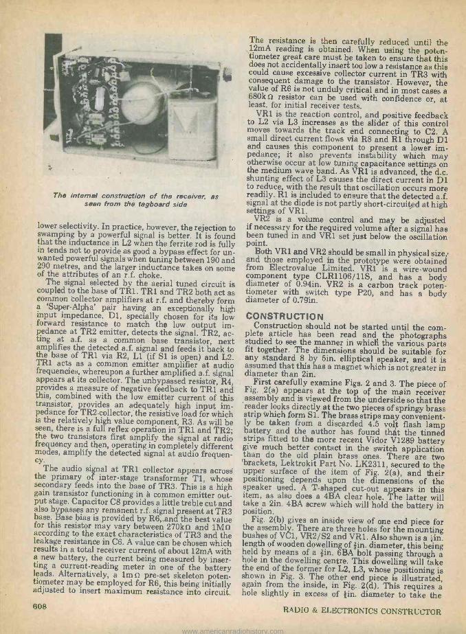
The internal construction of the receiver, as seen from the tagboard side
lower selectivity. In practice, however, the rejection to swamping by a powerful signal is better. It is found that the inductance in L2 when the ferrite rod is fully in tends not to provide as good a bypass effect for un- wanted powerful signals when tuning between 190 and 290 metres, and the larger inductance takes on some of the attributes of an r.f. choke.
The signal selected by the aerial tuned circuit is coupled to the base of TR1. TR1 and TR2 both act as common collector amplifiers at r.f. and thereby form a `Super -Alpha' pair having an exceptionally high input impedance. D1, specially chosen for its low forward resistance to match the low output im- pedance at TR2 emitter, detects the signal. TR2, ac- ting at a.f. as a common base transistor, next amplifies the detected a.f. signal and feeds it back to the base of TR1 via R2, Ll (if S1 is open) and L2. TRI acts as a common emitter amplifier at audio frequencies, whereupon a further amplified a.f. signal appears at its collector. The unbypassed resistor, R4, provides a measure of negative feedback to TR1 and this, combined with the low emitter current of this transistor, provides an adequately high input im- pedance for TR2 collector, the resistive load for which is the relatively high value component, R3. As will be seen, there is a full reflex operation in TR1 and TR2; the two transistors first amplify the signal at radio frequency and then, operating in completely different modes, amplify the detected signal at audio frequen- cy.
The audio signal at TR1 collector appears across the primary of inter -stage transformer T1, whose secondary feeds into the base of TR3. This is a high gain transistor functioning in a common emitter out- put stage. Capacitor C8 provides a little treble cut and also bypasses any remanent r.f. signal present at TR3 base. Base bias is provided by R6,, and the best value for this resistor may vary between 270kí2 and 1Mí1 according to the exact characteristics of TR3 and the leakage resistance in C6. A value can be chosen which results in a total receiver current of about 12mA with a new battery, the current being measured by inser- ting a current -reading meter in one of the battery leads. Alternatively, a 1m i2 pre-set skeleton poten- tiometer may be employed for R6, this being initially adjusted to insert maximum resistance into circuit.
The resistance is then carefully reduced until the 12mA reading is obtained. When using the poten- tiometer great care must be taken to ensure that this does not accidentally insert too low a resistance as this could cause excessive collector current in TR3 with consequent damage to the transistor. However, the value of R6 is not unduly critical and in most cases a 680k s1 resistor can be used with confidence or, at least, for initial receiver tests.
VR1 is the reaction control, and positive feedback to L2 via L3 increases as the slider of this control moves towards the track end connecting to C2. A small direct current flows via R8 and R1 through D1 and causes this component to present a lower im- pedance; it also prevents instability which may otherwise occur at low tuning capacitance settings on the medium wave band. As VR1 is advanced, the d.c. shunting effect of L3 causes the direct current in D1 to reduce, with the result that oscillation occurs more readily. R1 is included to ensure that the detected a.f. signal at the diode is not partly short-circuited at high settings of VR1.
VR2 is a volume control and may be adjusted if necessary for the required volume after a signal has been tuned in and VR1 set just below the oscillation point.
Both VR1 and VR2 should be small in physical size,' and those employed in the prototype were obtained from Electrovalue Limited. VR1 is a wire -wound component type CLR1106/ 11S, and has a body diameter of 0.94in. VR2 is a carbon track poten- tiometer with switch type P20, and has a body diameter of 0.79in.
CONSTRUCTION Construction should not be started until the com-
plete article has been read and the photographs studied to see the manner in which the various parts fit together. The dimensions should be suitable for any standard 8 by 5in. elliptical speaker, and it is assumed that this has a magnet which is not greater in diameter than 2in.
First carefully examine Figs. 2 and 3. The piece of Fig. 2(a) appears at the top of the main receiver assembly and is viewed from the underside so that the reader looks directly at the two pieces of springy brass strip which form Si. The brass strips may convenient- ly be taken from a discarded 4.5 volt flash lamp battery and the author has found that the tinned strips fitted to the more recent Vidor V1289 battery give much better contact in the switch application than do the old plain brass ones. There are two 'brackets, Lektrokit Part No. LK2311, secured to the upper surface of the item of Fig. 2(a), and their positioning depends upon the dimensions of the speaker used. A T-shaped cut-out appears in this item, as also does a 4BA clear hole. The latter will take a 2in. 4BA screw which will hold the battery in position.
Fig. 2(b) gives an inside view of one end piece for the assembly. There are three holes for the mounting bushes of VC1, VR2/S2 and VR1. Also shown is a ;in. length of wooden dowelling of fin. diameter, this being held by means of a fin. 6BA bolt passing through a hole in the dowelling centre. This dowelling will take the end of the former for L2, L3, whose positioning is shown in Fig. 3. The other end piece is illustrated, again from the inside, in Fig. 2(d). This requires a hole slightly in excess of fin. diameter to take the
608 RADIO & ELECTRONICS CONSTRUCTOR
www.americanradiohistory.com

(a) f
itted
her
e
3/4"
1/2°
+
/
3/8"
hole
for
3/4°
A. 1
/2
VR2/52
(b)
1/4`
leng
th o
f 3/8
" w
ood
dow
ellin
g
J
51/4
"
Bra
ss s
trip
clo
se
to p
anel
T-s
hape
d H
ok f
or 4
BA
x 2"
csk
bolt
ait -
out
w13
/8` 7/8-
1/
4"
e 43
4 2"
Tw
o an
gle
brac
kets
pla
ced_
to
fit
uppe
r sp
eake
r ho
les
23/4
' --
41
/2"
23/4
"
3/8"
hol
e fo
r V
C1
3/8"
hole
IN
SID
E
for
VR
1 1/
16"S
.R.B
P.
3 /2
'
13/4
"
B`
21/4
" 21
/2"
Ang
le b
rack
ets
plac
ed t
o fit
lo
wer
spe
aker
hol
es
Clip
s to
take
end
s of
L1 fe
rrite
rod
UP
PE
R
SID
E
1!4"
plyw
ood
(a)
UN
DE
R
SID
E
1/4"
ply
woo
d
51/4
"
(ail M
ai h
ere
Ove
rsiz
e 3/
8`ho
le
INS
IDE
1/16
`S.R
.B.P
.
3/8"
grom
met
cut
into
sha
pe o
f co
rn
(e)
I j311
6`
5/16
` II
1/16
"S.R
.B.P
.
(c)
(e)
(f
8x3/
8"di
a fe
rrite
rod
L
Nor
mal
3/8
"cen
tre
jgrommet
Con
trol
kno
b
fitte
d to
thi
s en
d
23/4
"
43/4
"
(d)
L1 -
500
turn
s 38
swg
enam
elle
d w
ire w
ound
to
2'le
ngth
on
3"sl
cevc
on
6`x3
/8'fe
rrite
rod
C
L2 -
115
turn
s of
34s
wg
enam
elle
d w
ire
3'sl
ceve
III'I
I
Fig
. 2(
a).
The
upp
er s
ectio
n of
the
rece
iver
ass
embl
y (b
). I
nsid
e vi
ew o
f the
con
trol
pan
el (c
). T
he b
otto
m
of t
he a
ssem
bly
(d).
T
he r
emai
ning
pan
el (
e).
The
cam
-sha
ped
grom
met
whi
ch a
ctua
tes
S1
(f).
T
his
s.r.
b.p.
gui
de f
its i
nto
the
T-s
hape
d cu
t-ou
t of
the
top
sect
ion
(g).
T
he l
ast t
wo
item
s fit
ted
on t
he 8
in.
to
ferr
ite r
od (
h).
Det
ails
of
coil
L 1
(i).
Win
ding
coi
ls L
2 an
d L3
II 91N
M
(h)
L3-I
Otu
rnso
f 34
swg
enam
elle
d w
ire
1.1/
4 gap
(i)
www.americanradiohistory.com

Upper view, illustrating the cut-out in the top section of the assembly
ferrite rod which passes into L2, L3. The positioning of the hole should match that of the *in. dowelling in Fig. 2(b). The square section cut from the lower right hand corner, as seen in Fig. 2(d), allows the passage of a small wooden mounting block in the case. Fig. 2(c) shows the base of the assembly, once more as viewed from the inside. This has two further brackets, Part No. LK2311, for speaker mounting, as. well as two spring clips, Lektrokit Part No. LK2721. The latter hold the ferrite rod for L3. It may be possi- ble to secure the brackets and the clips by means of the same screws and nuts, but if the shape of the speaker is such that the coil or ferrite rod would touch it, the clips will need to be mounted separately a little further back. The manner in which the four items just discussed fit together can be seen from the broken lines in Fig. 2(b) and Fig. 2(d). It will be apparent that, when the item of Fig. 2(a) is secured to those of Figs. 2(b) and (d), the brackets of Fig. 2(a) will be above the brackets of Fig 2(c). The speaker brackets should be positioned such that the front of the speaker, mounted by its four chassis holes, is very slightly inside the up- per edge (as seen in the diagram) of Fig. 2(c). This allows a piece of gauze to be slipped in inside the case later. The Lektrokit brackets and clips just mentioned are available, each in packets of 10, from Home Radio. The four pieces may now be cut out. They may then be temporarily assembled sufficiently firmly to allow the bracket and clip positions to be determined with the aid of the speaker to be used. The pieces may then be disassembled again and the brackets and clips mounted.
COILS The coils are next prepared. They may be wound on sleeves made up from pieces of Fablon. For L1 cut out a piece of Fablon measuring 4 by 3in., leaving on all the backing paper except for a strip fin. wide at one 3in. edge. Wrap the Fablon tightly around the 6in. ferrite rod at its centre, the exposed Sin. strip being wound on last so that it secures the completely rolled tube. A sleeve 3in. long is then given. Ll is wound as shown in Fig. 2(h). The 500 turns are scramble
wound, and the winding should progress gradually along the sleeve to take up an overall length of ap- proximately 2in. A useful approach here consists of marking off Sin. sections on the sleeve and winding 125 turns at a time in each. The coil ends may be secured with thin pieces of adhesive tape. The sleeve for L2, L3 also consists of a piece of Fablon measuring 4 by 3in. prepared in the same way as that for Ll to form a tube 3in. long. In this in- stance, however, the sleeve should be loose enough to allow the Bin. ferrite rod to move freely inside it. L2 and L3 are wound as indicated in Fig. 2(i). Both coils are close -wound. Instead of sleeves made of Fablon the prototype employed thin -walled s.r.b.p. (`Paxolin') tubes, these being given by a 6in. length of tubing with an outside diameter of min. (Home Radio) cut into two 3in. lengths. The tubing has a nominal inside diameter of *in. but some gin. ferrite rods will not fit inside it. ecause of this, the constructor is advised to employ the Fablon sleeves unless he already has access to the s.r.b.p. tubing and can check this physically with the ferrite rods to be employed. Next, take up a p.v.c. grommet with a lin. hole at its centre and cut it to the cam -like shape shown in Fig. 2(e). After this, cut out the s.r.b.p. piece of Fig. 2(f). This has another gin. grommet fitted in its cen- tral hole. These two parts are fitted on the 8in. ferrite rod in the positions shown in Fig. 2(g), the 4; and 2;in. dimensions from the end of the rod being to the grommet centres. A turn or two of Sellotape may be initially wound on the rod to ensure that the grommets are a tight fit on it. The cam -shape grommet should have its projection pointing upwards when the projec- tion on the s.r.b.p. piece is pointing downwards. A third grommet with a lin. central hole is also fitted on
Another view of the completed receiver. The knob shown is fitted over the ferrite rod
RADIO & ELECTRONICS CONSTRUCTOR
www.americanradiohistory.com
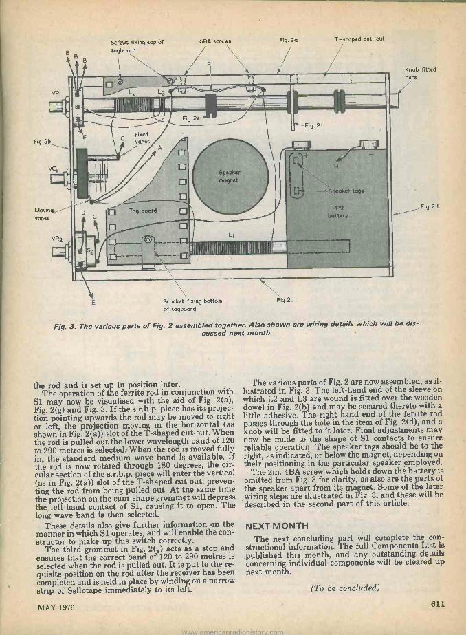
Screws fixing top of 6BA screws
B tagboard B
B Si
Bracket fixing bottom of tagboard
Fig. 2a T-shaped cut-out
Fig.2c
Fig. 2f
Knob fitted here
Fig. 3. The various parts of Fig. 2 assembled together. Also shown are wiring details which will be dis- cussed next month
the rod and is set up in position later. The operation of the ferrite rod in conjunction with
S1 may now be visualised with the aid of Fig. 2(a), Fig. 2(g) and Fig. 3. If the s.r.b.p. piece has its projec- tion pointing upwards the rod may be moved to right or left, the projection moving in the horizontal (as shown in Fig. 2(a)) slot of the T-shaped cut-out. When the rod is pulled out the lower wavelength band of 120 to 290 metres is selected. When the rod is moved fully in, the standard medium wave band is available. If the rod is now rotated through 180 degrees, the cir- cular section of the s.r.b.p. piece will enter the vertical (as in Fig. 2(a)) slot of the T-shaped cut-out, preven- ting the rod from being pulled out. At the same time the projection on the cam -shape grommet will depress the left-hand contact of Sl, causing it to open. The long wave band is then selected.
These details also give further information on the manner in which Si operates, and will enable the con- structor to make up this switch correctly.
The third grommet in Fig. 2(g) acts as a stop and ensures that the correct band of 120 to 290 metres is selected when the rod is pulled out. It is put to the re- quisite position on the rod after the receiver has been completed and is held in place by winding on a narrow strip of Sellotape immediately to its left.
Fig.2d
The various parts of Fig. 2 are now assembled, as il- lustrated in Fig. 3. The left-hand end of the sleeve on which L2 and L3 are wound is fitted over the wooden dowel in Fig. 2(b) and may be secured thereto with a little adhesive. The right hand end of the ferrite rod passes through the hole in the item of Fig. 2(d), and a knob will be fitted to it later. Final adjustments may now be made to the shape of Si contacts to ensure reliable operation. The speaker tags should be to the right, as indicated, or below the magnet, depending on their positioning in the particular speaker employed.
The 2in. 4BA screw which holds down the battery is omitted from Fig. 3 for clarity, as also are the parts of the speaker apart from its magnet. Some of the later wiring steps are illustrated in Fig. 3, and these will be described in the second part of this article.
NEXT MONTH The next concluding part will complete the con-
structional information. The full Components List is published this month, and any outstanding details concerning individual components will be cleared up next month.
(To be concluded)
MAY 1976 611
www.americanradiohistory.com

-SUGGESTED CIRCUIT H 306
Now that integrated circuit timers such as the 555 and 556 are available, timing cir- cuits incorporating discrete semiconductor devices are of less interest unless they possess a special feature not given by the integrated cir- cuit timers or employ a small number of inexpensive com- ponents.
The timing circuit to be described in this article just falls into the requisite category. It is expressly intended for operation from a 9 volt battery, and draws a very low current between tim- ing periods.. Also, it requires few com- ponents and employs two low-cost transistors only. It offers timing periods which are continuously variable from about 4 to 75 seconds, and the accuracy of the periods does not alter significantly with falling battery voltage down to some 7 volts.
A small shortcoming is that the relay in the circuit energises momen- tarily when the unit is initially switched on. If this is considered a dis- advantage a further switch can be inserted in series with the relay con- tacts this being closed after the main switch has been turned on.
CIRCUIT OPERATION The circuit of the timer is given in
the accompanying diagram. In this, Sl(a)(b) is the on -off switch and is shown in the "Off" position.
When the switch is set to "On", SI(a) applies the 9 volt supply to the circuit whilst Sl(b) disconnects the 33 n resistor, R3, from capacitor C2. The capacitor charges via the relay coil and the forward biased base - emitter junction of TR1, the charging current causing the momentary opera- tion of the relay which has just been mentioned. The capacitor charges
`ONE-SHOT'
ELECTRONIC TIMER By G. A. French
Relay contacts
111 -
To controlled circuit
SIa
R1
27kn
VR t- 500kn lin.
ACY 19
Lead -outs
o o o
bce
BC 214 L Lead -outs
S1 positions I - Off 2 - On
R2 22 kn
TR1
ACY 19
CI
005pF
Relay coil
TR2
BC 214L
DI
1
*1N4002
-9V
C2 200pF 10V wkg.
R3
33n
Sib 2
RI -R3 I/4 watt 10°/o
The circuit of the electronic timer. This requires few components and draws a very low current between timing runs
rapidly, and it then has very nearly the full 9 volts of the supply across its ter- minals.
The charging current turns TR1 hard on and, after C2 has charged, TR1 remains conductive by reason of the current flowing to its base through RI and VR1. Asa result, its collector assumes a voltage above chassis of 0.2 volt or less. This voltage is applied to
the base of silicon transistor TR2 which is, in consequence, cut off. No current flows in the collector of TR2, and the circuit is in one of its two stable states.
If push-button S2 is pressed, an energising voltage is applied across the relay coil. Also, the negative terminal of C2 is taken down to the positive supply rail, whereupon its positive ter -
612 RADIO & ELECTRONICS CONSTRUCTOR
www.americanradiohistory.com

minai is taken 9 volts positive of that rail. TR1 is at once cut off and it draws no collector current through R2, whereupon a base bias current flows via R2 to TR2, and this transistor turns on. The circuit is now in its se- cond stable state, with TRi turned off and TR2 turned on. The closure of S2 can be very quick as, due to a regenerative effect between the two transistors, it is merely necessary for TR1 base to be taken slightly positive for the circuit to change state.
C2 next discharges via RI and VR1. After a period of time, which depends upon the setting of VR1, the positive terminal of C2 takes the base of TRI slightly negative of chassis potential and TR1 commences to conduct, drawing current through R2 and reducing the base bias current available for TR2. There is again a regenerative effect and it results in TR1 being turned hard on and TR2 being cut off. Again, C2 becomes charged to nearly the full supply voltage via the relay coil and the base - emitter junction of TR1.
To sum up, pressing S2 causes TRI to turn off, TR2 to turn on and the relay to energise. After a time dictated by the setting of VR1, the circuit reverts to its previous state with TR1 on, TR2 off and the relay de -energised. A further timing period can then be in- itiated by pressing S2.
Observant readers will note that the circuit is really a monostable, or `one- shot' multivibrator.
DISCHARGE PERIOD As with a standard multivibrator, the
discharge period in C2 following the closure of S2 is approximately equal to 0.7 times the time constant of C2 and the total resistance of Rl and VR1. When VR1 inserts zero resistance into circuit this calculates as 3.8 seconds and, when VRI inserts maximum resistance, as 74 seconds. In practice, there will he fairly wide divergencies from the calculated values due to tolerances in R1, VR1 and, in particular C2. With the prototype circuit the timing range was approx- imately 4 to 85 seconds.
The timing period is independent of battery voltage if, during discharge, the négative terminal of C2 is at chassis potential, and if the discharge ends when its positive terminal also reaches chassis potential. In practice the negative terminal is held at about 0.2 volt above chassis by TR2, and the positive terminal rises to about 0.1 volt above chassis at the end of the dis- charge period. This is one reason why TR1 is a germanium instead of a silicon transistor. A second reason is that the maximum reverse base - emitter voltage rating of the germanium transistor specified for TRi is 12 volts, whereas most silicon transistors have reverse base -emitter voltage ratings around 5 volts only. Had a sili- con transistor been used a diode would have had to be inserted between its base and the junc-
tion of VR1 and C2 to isolate these two components from the base during the discharge period. Even with a ger- manium diode the positive terminal of C2 would then have had to rise to some 0.7 volt above chassis level before TR1 turned on, and such a voltage figure would be too high to allow timing periods to be independent of battery voltage. With a germanium transistor in the TRi position the base voltage at the end of the timing period is, as already stated, 0.1 volt only, and this much smaller figure can be assumed to allow the circuit to be almost com- pletely independent of battery voltage within reasonable limits. The prototype circuit was run a number of times, with VR1 set to the maximum timing period, at supply voltages of 9 and then 7 volts. No discernable differences in period length were observed.
When the unit is switched off, Sl(b) causes C2 to be fully discharged by way of the current limiting resistor R3. In consequence it charges up again via the relay coil and TR1 base -emitter junction after switch -on. If Sl(b) and R3 are omitted, and Cl is left in a charged condition after switch -off, the circuit tends to go through a full timing period when it is switched on again.
A critical feature of the circuit is that, when TRI is on and TR2 is off, the high level of amplification available causes the circuit to be sen- sitive to any small positive excursions which may appear at TR1 base; and these can trigger the circuit into its alternate state with TRI off and TR2 on. A sudden small reduction in supply voltage can cause TR1 base to go positive by way of the relay coil and C2. In consequence it is not recommended that the circuit be run from a simple unregulated mains power supply since reductions in mains voltage could conceivably trigger TR1 off. There are no problems at all in this respect if the circuit is run from a battery or from a voltage stabilized mains supply. Cl is includ- ed as a precaution against triggering by transients, as could occur if VR1 had a "noisy' contact between slider and track, and were adjusted quickly. It may be found that the circuit is triggered if the armature of the relay is
Dear Mr. Plomley, please send eight more 'Desert Island Discs'. The last lot
tasted lovely .. .
pressed down quickly. Should it occur, this effect is not a fault sympton but merely demonstrates that the relay produces a momentary voltage when its magnetic circuit is suddenly com- pleted.
During the time when S2 is pressed, the negative terminal of C2 is at chassis potential, rising to 0.2 volt above chassis when S2 is released. The small difference between these two potentials should not upset timing ac- curacy, particularly as S2 is pressed at the start of discharge in C2. The length of time during which S2 is closed is un- controlled, but it will obviously be much shorter than even the shortest timing period of around 4 seconds.
Turning to components, D1 is the usual diode which is connected across the relay coil to prevent the appearance of a high back-e.m.f. when it releases. The relay used by the author was a "Miniature Open P.C. Relay" with 41012 coil which is available from Doram Electronics. Although not checked by the author, any other relay energising at around 6 volts and with a coil resistance between 400 S2 and some 700 f2 should function equally well. If a P.O. 3000 type of relay is used, its somewhat sluggish operation at low energising voltages may prevent it responding to the initial surge of charging current in C2 immediately after switch -on. S1(a)(b) requires a break -before -make action, and this will automatically be given if a d.p.d.t. toggle switch is used here. C2 should be a modern component in good condition, as also should VR1.
The current drawn from the 9 volt battery when the relay is de -energised is 0.4mA when VR1 inserts maximum resistance into circuit, this rising to 0.8mA when it inserts minimum resistance. The current is ap- proximately 22mA when the relay (if this is of the type employed by the author) energises.
When the circuit has been assembl- ed, several timing runs may be carried out to confirm that operation is correct and to ensure that C2 is fully "formed". Calibration is then carried out by adjusting VR1 to different set- tings and checking the resultant timing periods with a watch having a sweep second hand.
MAY 1976 613
www.americanradiohistory.com

FOR DX LISTENERS
By Frank A. Baldwin
Times = GMT
Whilst listening around the various broadcast bands during each month obtaining material for this article, it quite often happens that one unexpectedly hears an unusual or new signal. A new station perhaps, or an old one on a new channel, a station logged for the first time after months of fruitless effort or even a previously unheard tuning or interval signal. Such an event occurred recently. Gaberone, Botswana, may be heard on 4845 where it operates from 0400 to 0600 and from 1430. through to 2000 (until 2100 Fridays to Sundays). The station is fairly often reported in the SWL press, usually around the 1800 to 2000 time period, this also apply- ing to my logbook times. Tuning around recently, the dial pointer aligned with the above -mentioned fre- quency at 0345 at which time a few tinkling bells could be faintly heard. Over the next few minutes the bells became louder in what was obviously a repeated recording. Looking up the information on this fre- quency elicited the information that this was the in- terval signal of Gaberone and was in fact cow bells. This signal was heard until 0400 then a choral National Anthem, an announcement by YL in the Setswana language followed by a short prayer by OM in English. What the text book doesn't mention however is that the voice of the heardsman calling his
cattle is also to be heard amid the jangle of cowbells! Any other new signals? Well, the log shows recep- tion of Radio Sana, Yemen, on a measured 4853 since way back in mid -January at which time we had it listed as an unidentified station. It is a relay of the domestic service and the log time entry was at 1629. Or what about Hanoi on 9839 in parallel with 7512 from 1412 onwards with a programme in Lao to,
Laos (where else!) in the External Service. CURRENT SCHEDULES
TAIWAN "Voice of Free China", Taipeh, has a programme in English directed to Africa and Europe from 2000 to 2100 on 9510, 11860, 15370 and on 17720. POLAND "Radio Warsaw" operates an External Service in which English programmes are provided for Europe as follows - from 0630 to 0700 on 7270, 7285 and on 9675; from 1200 to 1230 on 7285 and 9540; from 1600 to 1630 on 6095, 7125, 7285 and 9540; from 1830 to 1900 on 6095, 7285 and 9540; from 2030 to 2100 on 6095 and 7285 and from 2230 to 2300 on 3955, 5995, 6135, 6155 and on 7285. HUNGARY "Radio Budapest" schedules programmes in
English to Europe from 1200 t4 1240 (not Saturdays or Sundays) on 7155, 7215, 9585, 9833,
Frequencies = kHz
11910, 15160 and on 17715; from 2130 to 2200 on 5965, 6005, 7150, 7220, 9655, 11910 and on 15415.
A DX programme in English is featured on Tuesdays and Fridays from 1515 to 1530 on 6025, 6110, 7200, 7215, 9585, 11910 and 15415. ALBANIA "Radio Tirana" radiates in English to Europe from 0630 to 0700 on 7065 and 9500; from 1630 to 1700, 1830 to 1900, 2030 to 2100 and from 2200 to 2330 oni 7065 and 9480. INDIA "All India Radio", Delhi, broadcasts programmes in English in the General Overseas Service as follows - to East Africa, the U.K. and West Europe from 1745 to 1945 on 7225, 9525, 9575, 11620 and 15080; to North and West Africa, the U.K. and Western Europe from 1945 to 2045 on 7225, 9525, 9755.9912. 11620 and on 11880; to the U.K. West Europe Australasia 2045 to 2230 on 7150, 7225, 9525, 9912, 11620 and on 11740. SPAIN "Radio Nacional de Espana", Madrid, does not present any programmes in English to the U.K. of Europe but schedules some to North America which may be heard here in Britain. The broadcast to N. America is from 0100 to 0400 (Sundays excluded) on 6065 and 11880. OMAN The Domestic Service mainly in Arabic from Muscat is radiated.from 0300 sign -on to 2010 sign -off on 6175 and on 11890. There is however a pro- gramme in English which is also intended for listeners abroad, this being radiated, on 11890 from 0900 to 1100.
AROUND THE DIAL CHINA Foochow on 4975 at 2101, OM in Chinese, military music complete with stirring male chorus. This is Foochow 1 which operates from 0740 to 1600, from 2050 to 0540, additionally radiating a programme directed to Taiwan from 1600 to 1810. Kunming on a measured 4759 at 1605 with OM and YL alternate in Chinese, signing off at 1620 with a choral version of the "Internationale". Schedule is from 0950 to 1620 and from 2150 to 0800. Fukien on 3300 at 1553, talk in Chinese, short ex- cerpts of Iocal music. The latest schedule I have of this one is from 1000 to 1902 in Amoy and Standard Chinese in Network 2.
Radio Peking on 7010 at 2056 when signing -off 814
RADIO & ELECTRONICS CONSTRUCTOR
www.americanradiohistory.com

with the "Internationale" after a programme of Chinese music.
Lanchow on 4865 at 1512 with a Chinese drama production.
Radio Peking on 6645 at 1404, OM and YL in Kazakh in the Domestic Service, this programme be- ing presented from 1400 to 1455, also in parallel on 8565.
Another late winter visitor has been Urumchi on 4970 at 1457 just audible when signing -off with the "Internationale" after the Kazakh programme.
AFRICA African stations can be quite interesting in
programme content, indeed much of the local music and orchestration is bgrely distinguishable from the modern U.K. pop scene! Some of the African stations are relatively easy to log whilst others are most cer- tainly not in that category, low powers and surroun- ding commercial interference are, as usual, the enemies.
ZAIRE Lubumbashi on 4950 at 1920 with a programme
of African music complete with vocals by both OM and YL. This is the Home Service, the schedule of which is from 0400 to 0700, 1000 to 1245 (Saturdays 2100), 1500 to 2100 (Sundays from 0400 to 2000). The power is 10kW. Known to "wander", I once measured this one 4751.5 kHz.
LIBERIA Monrovia on 3227 at 0639, African music with,
YL's in chorus. This is Radio Station ELWA (Eternal Love Winning Africa) an evangelical broadcaster, this channel being that for local vernaculars. The schedule is from 0610 to 0800 and from 1805 to 2220, the power is 10kW.
MALAWI Blantyre on 3380 at 0642 with a programme of
local flute music. Schedule is from 0257 to 0520 and from 1700 to 2210 (from May to August 0257 to 1110 and from 1300 to 2210). The power is 100kW and that usually makes this one a fairly easy proposition.
SENAGAL Zinguinchor on 3336 at 1958, light music
programme with announcements in French. Not so easy to receive, this one has a schedule from 0600 to 0800 and from 1800 to 0000, the power being just 4kW.
KENYA Nairobi on 4915 at 0548, religious service in
Swahili. This is the Home Service, scheduled from 0255 to 0630 and from 1430 to 2015 (Saturdays to 2115). The power is 100kW which also makes for com- parative ease of reception.
NIGERIA Kaduna on 3396 at 0600, talking drum interval
signal, 6 pips, identification in English by YL and then a newscast of local events in English by OM. The talking drum interval signal must be heard to be believed - incredible! During the war with Biafra we often logged this interval signal prior to the news in English and the exhortation "There's here's a job to be, done, the war must be won."
Ibadan on 3204 at 0625, religious service in
Yoruba. I logged the service the schedule tells me it is in Yoruba! Not so easy to log, Ibadan has a schedule from 0430 to 0730 and from 1430 to 2305 and the power is 10kW.
MALAGASY Tananarive on 3287 at 0615, recording of local
pops. Schedule is from 0230 to 0500 and from 1430 to 1930 (Home Service 1). The power is 4kW.
BURUNDI Bujumbura on 3300 at 0415, typical African music
with YL's in chorus. This is the Home Service 1,
scheduled in French and vernaculars from 0330 to 0600 (Sundays to 2100) and from 1600 to 2100. The power is 25kW but this doesn't make it an easy one to receive - the surrounding interference takes care of that!
NIGER N aimey on 3260 at 0602, OM with a local newscast
in French. Schedule is from 0530 to 0630, 1700 to 2200 (Saturdays from 1700 to 2200 and from 1500 to 2300, Sundays from 1700 to 2130). The power is 4kW.
From all of which may be deduced that one of the best times to listen for those elusive and not so elusive African stations is around 0600 or so.
LATIN AMERICA Changing the target area and aiming for stations in
this part of the world why not set your sights on the rarely reported Voz de los Caras?
EQUADOR Voz de los Caras, Bahia de Caraquez, logged at 0418
with a programme of a particular local style of music in which only a guitar and drum are used, this follow- ing a clear station identification by OM announcer. We measured the frequency as 4794.5 but Voz de los Caras has been known to drift between the limits 4792 to 4796. Like the frequency, the schedule can also vary but in general it is from 1100 to 0500.
Radio Cenit, Portoviejo, on a measured 4772 at 0430, local music and songs prior to identification, the National Anthem and sign -off.
Radio Popular, Cuenca, on 4800 at 0618 and still at good signal strength with songs in Spanish after identification.
BOLIVIA Radio Universo, La Paz, on 5005 at 0425, records
of dance music in Euro-style and announcements in Spanish.
HONDURAS Radio Progresso, El Progresso, on 4920 at 0440,
YL with songs, guitar solo. The evening schedule is from 2200 to 0500 and the power is 10kW.
DOMINICAN REPUBLIC Radio Clarin, Santo Domingo, on 4850 at 0434,
OM with clear identification then into programme of local songs. Schedule is from 1000 to 0415, obviously on an extended transmission period on this occasion -a practice common with Latin American stations.
BRAZIL Radio Gazeta de Alagoas, Meceio, on a measured
3326.2 at 0400, local music and songs then clear identification and sign -off without National Anthem.
MAY 1976 615
www.americanradiohistory.com
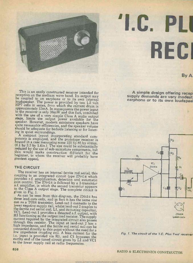
This is an easily constructed receiver intended for reception on the medium wave band. Its output may be coupled to an earphone or to its own internal loudspeaker. The power is provided by two 1.5 volt HP7 cells in series, from which the current drain is approximately 12mA. In consequence the power input to the receiver is only 36mW and this fact, combined with the use of a very simple Class A audio output stage, limits the output power available for the speaker. However, modern miniature speakers have quite reasonable efficiencies, and the speaker volume should be adequate for bedside listening or for listen- ing in quiet surroundings.
A compact layout incorporating standard com- ponents is employed, and the prototype receiver is housed in a case measuring some 155 by 85 by 40mm. (6.1 by 3.3 by 1.6in.). The size could be substantially reduced by the use of sub -miniature components, but this would make construction difficult for the beginner, to whom the receiver will probably have greatest appeal.
THE CIRCUIT The receiver has an internal ferrite rod aerial, this coupling to an integrated circuit type ZN414 which provides r.f. amplification, detection and automatic
gain control. The ZN414 is followed by a 2 -transistor a.f. amplifier, in which the second transistor appears in the Class A output stage. The complete circuit is given in Fig. 1.
As can be seen from this diagram, the ZN414 has three lead -outs only, and in fact it has the same size can as a T018 transistor. Lead -out 3 connects to the lower negative supply rail, whilst lead -out 2 couples to the ferrite rod aerial coil, Ll, and its tuning capacitor, VC1. Lead -out 1 provides a detected a.f. output, with R3 functioning as the output load resistor. The supply current required by the integrated circuit also passes through this resistor. The input at lead -out 2 has a high impedance, and the ferrite rod aerial coil can be connected directly to this point without the need for a low impedance coupling coil. A bias current for the i.c. input is provided via R1, and Cl bypasses the earthy end of the tuned circuit given by Ll and VC1 to the lower supply rail at radio frequencies.
I.C. PLI
RECI By A.
A simple design offering recepr supply demands are very modest earphone or to its own Ioudspeal
RI
YVVV
L1
V
ICI ZN414
Z N414 Lead-outs
VR1
Fig. 1. The circuit of the Y.C. P/us Two' receiver.
618 RADIO & ELECTRONICS CONSTRUCTOR
www.americanradiohistory.com

'LC. PLUS TWO' R
l for may rnal volt in is :put fined Itput
the have urne ;ten-
;orn- er is mm. ially ,but the
have
this hich iatic istor rears tit is
has size the
es to ;itor, with pply tsses as a n be for a
the the
VC].
RECEIVER By A. P. Roberts
A simple design offering reception on the medium wave band. Battery supply demands are very modest and the receiver offers an output to an earphone or to its own loudspeaker at a low level for bedside listening.
ICI
ZN 4I4 LI
VCI
ZN414 Lead -outs
BCIO9C Lead -outs
sI +3V
Fig. 1. The circuit of the Y.C. Plus Two' receiver. This operates from the low supply voltage of 3 volts
RADIO & ELECTRONICS CONSTRUCTOR MAY 1976
www.americanradiohistory.com

Two, VER
oberts
n the medium wave band. Battery e receiver offers an output to an a low level for bedside listening.
+3V
BC 109C Lead -outs
operates from the low supply voltage of 3 volts
COMPONENTS Resistors (All fixed values miniature ' watt 10%)
R1 100k n R22.2kû2 R3 680 n R4 100 0 R5 1.2M SZ
R6 3.9k R7 56k 0 VR1 5k SZ potentiometer, log
Capacitors Cl 0.1µF type C280 (Mullard) C2 0.11LF type C280 (Mullard) C3 0.01µF type C280 (Mullaru) C4 6.84F electrolytic, 10 V. Wkg. C5 0.224F type C280 (Mullard) C6 41.4F electrolytic, 10 V. Wkg. C7 0.1µF type C280 (Mullard) C8 1001./F electrolytic, 10 V. Wkg. CX 0.047µF type C280 (Mullard) VC1 208pF variable air -spaced (see text)
Inductors Ll Ferrite aerial coil (see text) T1 Output transformer type LT700 (Eagle)
Semiconductors IC1 ZN414 TR1 BC109C TR2 BC109C D1 0A200 D2 0A200
Switch S1 d.p.d.t. slide
Socket JK1 3.5mm. jack socket with break contact
Speaker LS1 3 n or 8 S2 speaker, 64mm. (2.5in.) round
Miscellaneous Plastic or wooden case (see text) Battery holder type BH.2 (Eagle) 2 -off HP7 cells Battery connector 2 -off control knobs Ferrite rod, 95 x 9.5mm. (see text) Veroboard, 0.lin. matrix Speaker fabric 34 s.w.g. wire, enammelled, d.c.c. or d.s.c. Connecting wire, etc.
MAY 1976 617
www.americanradiohistory.com

The recommended supply potential, at the upper end of R3, is 1.3 volts. A voltage at approximately this level is provided by means of R2 and the stabilizing circuit given by R4, D1 and D2. The latter are two forward biased silicon diodes which each drop a
steady voltage of about 0.6 volt. The total voltage across the diodes, plus an additional small voltage across R4, is then approximately 1.3 volts, as is re- quired. C2 functions as an r.f. bypass capacitor.
AUDIO STAGES The a.f. output from lead -out 1 of the ZN414 is
applied, via C4, to the volume control VR1. The signal tapped off by the slider of VR1 is then passed by way' of C5 to the base of TR1, which provides most of the a.f. voltage gain in the receiver. It is connected in the common emitter configuration and has R5 as its base bias resistor and R6 as its collector load resistor. C7 filters out any residual r.f. signal which is still present. C6 couples the a.f. signal from the collector of TR1 to the base of TR2 in the output stage.
TR2 is also connected in the common emitter mode, with R7 as its base bias resistor. The collector load is given by half the primary of Tl. This transformer is used to match the output impedance of TR2 to the lower impedance of the speaker. It also serves to isolate the speaker from the standing direct current in TR2 collector circuit.
Jack socket JK1 has a break contact which cuts out the speaker when the earphone plug is inserted.
The capacitor shown as CX may be required in order to prevent instability at high volume control set- tings, and this point is discussed more fully later on. C8 provides supply decoupling, and S1 is the on -off switch.
COMPONENTS Most of the components are standard readily ob-
tainable items, but a few require some comment. A manufacturer's surplus air -spaced capacitor was
used for VC1 in the prototype, and any reasonably small component having a maximum value of 208pF or a little more may be employed here. An air -spaced capacitor is preferable to a solid dielectric type. A single gang Jackson type 01 capacitor with a value of 208pF is listed by Home Radio and this would be suit- able.
Looking into the receiver from the rear. The layout is compact without undue crowding of
parts
-19mm
1111111111111111 :.
75 turns of 34 s.w.g.
Lead -outs about 100mm long
Ferrite rod
Fig. 2. Details of the ferrite rod aerial winding
The two HP7 cells are retained in an Eagle BH.2 battery holder, or similar, in which they are fitted side by side. The holder is provided with snap terminâls. It is available from several suppliers, including Henry's Radio.
The ferrite rod in the prototype had a length of 95mm. (3*in.) and a diameter of 9.5mm. (tin.). It is not essential to use a rod of exactly the same length and a 101mm. (4in.) rod of the same diameter may be employed instead.
FERRITE AERIAL The ferrite aerial coil is wound on the rod by the
constructor. This is quite an easy process as only the one winding is required. The coil wire is 34 s.w.g. enamelled, d.c.c. (double cotton covered) or d.s.c. (double silk covered) copper wire, and the coil con- sists of 75 turns wound side by side. Fig. 2 gives details.
The winding commences 19mm. from one end of the rod, the wire at the start being secured to the rod with plastic insulating tape. The turns are then wound on as neatly as possible in a single layer, after which the winding end is secured with another piece of in- sulating tape. The two free wire ends should be fairly long, say about 100mm. each. 'l'hey can be shortened as necessary when the coil is later connected into the receiver circuit.
COMPONENT PANEL The small components are assembled on a piece of
0.lin. Veroboard having 28 holes by 12 copper strips. The component side of the panel is illustrated in Fig. 3.
Commence by carefully cutting out a panel of the specified size with a small hacksaw. Then drill out the single mounting hole with a No. 41 (0.096in.) twist drill or a drill of similar size. Next, make the seven breaks in the copper strips at the points listed in Fig. 3, using a Vero spot face cutter or a small twist drill.
The single link wire is fitted to the panel, followed by the resistors and capacitors with the exception of CX. The mounting lugs of Ti are bent up at 90 degrees so that the transformer can be positioned flat on the board without having to drill out holes for its lugs. One lug is bent round and under the panel edge, its end being soldered to copper strip L. The other lug may be secured to the board with a Iittle adhesive.
618 RADIO & ELECTRONICS CONSTRUCTOR
www.americanradiohistory.com

Mounting hole
VC1
K o
VR1
A
B
C
D
E
F
G
H
VR1
I 2 3 4 5 6 ' 7 8 9 10 II 112 13 14 15 16 17 18 19 20 21 22 23 24 25 26 27 28
O 0 0 0 R4
'00 o
VCj
R1
! 1
C3 o
2 0
o ICI
O 3 0
0
0
oR2
o
0
III
o o I oR o 5
o c o 'o
o o o C5
0 0 0
ó TR1 + o
o b o
0 0 0 0 0 0
0 0 0 0 0 0
0 0
0 0 0
0 0 o o oJK1 o
0 0 0 0 0 0 0
0 0 0 0
0 0
T1
® o C6 o o
o
0 o I
CX 0 0
Direction of strips
Cut strips at I-II,J-II,B-6,H-17, F-17, F -24,J-24.
Fig. 3. The components are assembled on the Veroboard panel in the manner shown here
0 0 0
0 0 0 0 0
s1
Before mounting the transformer, the three primary leads are threaded through and soldered at holes F20, H2O and J20, and the two secondary leads at F25 and J25. The leads should be cut fairly short, and should be kept under, or close to, the transformer bobbin after mounting. It is in order to connect the unused primary lead at hole F20, as no other connection is made to the strip section concerned.
It must be pointed out that an output transformer other than the LT700 should not be used. The physical layout on the panel has been designed to suit this particular transformer. Also, other transistor out- put transformers will almost certainly have a much lower primary impedance.
Finally, wire in and solder the two transistors and the integrated circuit. The wires connecting to exter- nal components are added Later.
CASE AND WIRING A case for the receiver may be home -constructed, or
may consist of a plastic case of the requisite dimen- sions. It must, of course, be large enough to take the components, including the speaker, and may have the general dimensions mentioned earlier.
A home -constructed ease is not difficult to assem- ble, and it can be made up of thin plywood with sim- ple butt joints. A neat finish is given by covering it, after completion, with one of the self-adhesive plastic materials, such as Fablon.
A metal case must not be employed as this will screen the ferrite rod aerial and prevent signal pick- up.
LS1
Lug taken round edge of panel
Neg. battery clip
The general layout and interconnecting wiring of the receiver is shown in Fig. 4. S1 is mounted on the right hand side of the case, as viewed from the rear. It requires a rectangular cut-out, and this may be made with the aid of a fretsaw. Two short 6BA bolts and nuts are employed for mounting the switch. It is a standard d.p.d.t. (double -pole double -throw) type but is used here as an s.p.s.t. (single -pole single -throw) component. In consequence, connections are made to only two of its six tags.
A close-up view of the component panel
MAY 1976 619
www.americanradiohistory.com

The aperture for the speaker may also be cut out with a fretsaw. A piece of speaker fabric is glued behind this, after which the speaker is glued, in turn, to the fabric. Take care to ensure that none of the glue is allowed to get on the speaker cone or surround. The speaker may, alternatively, be bolted in position, assuming that it has mounting holes and that the appearance of screw heads on the front panel of the case is acceptable. Make sure that there is enough space for the battery holder to fit below the speaker magnet.
Most air -spaced variable capacitors are provided with three 4BA tapped holes on the front plate for mounting. The front panel of the case is drilled with a 10mm., diameter hole for the capacitor spindle, and with three 4BA clearance holes for the mounting screws. The positions of the mounting holes may be deter- mined by first holding a piece of paper to the capacitor front plate and marking out the holes on these. The paper may then be used in the manner of a template to mark out the corresponding holes on the case front panel. The mounting screw ends must not pass more than marginally inside the capacitor front plate as they may then damage the fixed or moving vanes. In consequence, short 4BA bolts are required, and it will be found helpful to fit a few 4BA washers over each bolt between the case front panel and the front plate of the capacitor.
The component panel fits below VC1. A piece of 6mm. plywood measuring approximately 25 by 38mm. is glued to the inside of the front panel below
Moving vanes Fixed vanes
VC1, and the component panel is then secured to this by a small woodscrew passing through the hole at D10. A small insulating washer, or a grommet, between the panel and the plywood will ease strain on the panel, and the screw should not be tightened ex- cessively. If the right hand edge (as viewed from the rear of the receiver) of the panel is close to or touches the speaker frame, a further spacing washer or washers may be used. Also, the appropriate surface of the speaker frame may be covered with plastic in- sulating tape.
VR1 and JK1 are mounted on the left hand side (again as viewed from the rear) of the case. VR1 re- quires a 10mm. diameter hole. Most 3.5mm. jack sockets require a 7mm. mounting hole. The jack socket shown in Fig. 4 is a type having a closed con- struction. If the socket to be employed has an open construction, the three leads to it will conrect to its tags as indicated in the inset diagram, the letters X, Y and Z corresponding to the similarly designated wires in the main diagram. The tag layout in the inset is that encountered with standard jack sockets; if any doubt exists here the appropriate tags may be iden- tified by visual inspection and the socket wired up to akree with the circuit diagram of Fig. 1.
A wooden block measuring 12.5 by 12.5 by 25mm. provides a mounting for the ferrite aerial rod. The block has a deep V-shaped groove cut, by means of a hacksaw, along the centre of one of the 12.5 by 25mm. sides. The rod is then glued into the groove and the block, complete with aerial rod, glued to the top inside
Wooden mounting block
w J 4K7i l ..-al Ç_I Y
JK1 a IMP"
*, \ B-12 A-28 \
C-4
G-3 F-26
O O \ O VIRI
..
J-1 Component J-26 panel
L-1 L-28
ms
Y
I Alternative connections to AI
Fig 4. Layout of the parts of the receiver inside the case, together with the interconnecting wiring
620 RADIO & ELECTRONICS CONSTRUCTOR
www.americanradiohistory.com

Another illustration of the completed receiver
of the case. A good quality gap filling adhesive, such as an epoxy resin, is required here. Ll must not be positioned too close to the .speaker magnet, or sen- sitivity may be reduced.
When all the components have been mounted, but before the component panel is screwed down, com- plete the wiring shown in Fig. 4. Apart from the ferrite aerial coil leads, all the interconnecting wiring should employ thin flexible insulated wire. The lead -outs from L1 connect directly to VC1, as shown. These connections should be of a temporary nature at this stage as it may be necessary to transpose them.
When all the wiring has been completed and check- ed, the component panel may be mounted. Next fit the control knobs, and connect up the battery holder with cells inserted.
ADDING CX The receiver may now be tried out. No alignment is
required as there is only a single tuned circuit. If instability should appear at high volume settings,
causing a whistle to be produced as the set is tuned across a station, the probable cause is feedback between the speaker and aerial coils. First, check whether the instability can be cleared by reversing the connec- tions from L1 to VC1. If this does not effect a cure, further r.f. filtering in the receiver circuit can be provided by fitting CX to the component panel in the position shown in Fig. 3. There is no need to add CX unless instability at high volume settings is apparent. After this particular check has been carried out, the connections from L1 to VC1 may be made of a perma- nent nature.
There is a slight possibility that instability at all volume settings may occur with some specimens on the ZN414, and the cure in this case is to slightly reduce its supply voltage by replacing R4 on the com- ponent panel with a short link wire. This should only he done if the instability appears as, otherwise, sen- sitivity will be reduced unnecessarily.
The completed receiver is now ready for use, and the back of the case can be screwed on. As a finishing touch, `Panel -Signs' legends (available from the publishers of this magazine) may be added to indicate control functions and to show station locations around the knob for VC1. The earphone socket can be used as an output for any of the normal types and impedances of earphone.
RADIDitELEC 1;11 I [Piit' CONSTRUCTOR
IN NEXT MONTH'S ISSUE HOMODYNE S.S.B. RECEIVER
FOR 80 METRES Part 1 (two parts)
In this ingenious receiver design an aerial input is applied direct to the product detector, a Motorola MC1496 integrated circuit. A local oscillator running at carrier frequency then enables demodulation to be given both for s.s.b. and c.w. signals. Due to this direct conversion technique there are only two tuned circuits, one operating at aerial frequency and the other at oscillator frequency. The description of the receiver will be completed in the following
month's concluding article. * * *
NICKEL CADMIUM CELL CHARGER
Rechargeable nickel cadmium cells are becoming increasingly popular in these days of rising battery costs. Because of their low inter- nal resistance they should preferably be charged by constant current sources, and this article describes a unit which is capable of charging up to four 'AA' size nickel cadmium cells. These are similar to standard HP7 dry
cells.
* * * LOW -VALU E
OHMMETER Capable of reading resistance values down
to 0.10. This very simple instrument requires few components and offers a high level of ac-
curacy.
ALL THE USUAL FEATURES PLUS
MANY OTHER ARTICLES ON SALE let JUNE
35p
:I,I iIDllilad l ailllle CONSTRUCTOR
MAY 1976 621
www.americanradiohistory.com

AMBIPHONIC ADAPTER Part 2 by R. A. Penfold
This concluding article completes the constructional information for the am- biphonic adapter. Also described are the processes of setting up and balancing, and of taking the left and right hand input
signals from the stereo amplifier.
In last month's issue we examined the basic opera- tion of the ambiphonic adapter, discussed its circuit and then described the first steps in construction. We now continue with the constructional details. GENERAL LAYOUT
The general layout of the two printed boards, the mains transformer and other components in the adapter can be seen in the photographs. The position- ing of the parts is not unduly critical, but, in the in- terests of obtaining a low hum level, it is best to mount the transformer as far to the left of the chassis as possible and to have the amplifier board at the ex- treme right of the chassis.
The amplifier board is illustrated, actual size, in Fig. 6, and this diagram may be traced. Note that VR1 and VR2 are miniature 0.1 watt skeleton poten- tiometers having 0.2in. (5.1mm.) spacing between the two track tags, with the slider tag 0.4in. (10.2mm.) from a line drawn between the track tags. There are two 6BA clear mounting holes in the board, and these may be used to mark out the corresponding 6BA clear holes in the chassis. The board is mounted, later, with these holes to the right on the chassis. 6BA lin. bolts are employed .for this mounting, with lin. metal spacers on them to keep the board underside spaced away from the chassis surface. The board takes up its chassis connection by way of these spacers.
There are a number of thin flexible flying leads from the board and these may be cut a little longer than is required, being shortened as necessary when they are finally connected to the external components. Components in the right rear channel are identified by the suffix letter "a", as was explained last month. The board is not finally mounted yet.
Most of the power supply components are assembl- ed on a second printed board and this is shown in Fig. 7. Again, the diagram is reproduced actual size. The miniature skeleton potentiometer, VR6, has the same tag spacing as VR1 and VR2.
There are two 6BA clear mounting holes, which may be used for marking out the corresponding holes in the chassis. When mounted, the board has these two holes to the right. Metal spacers are employed to space off the board from the chassis so that the mains lead can pass underneath it. As with the amplifier board, the power supply picks up its chassis connec- tion via these spacers.
The flying leads from the board are made a little longer than necessary, being cut down as required when they are connected. The three leads to the mains transformer secondary are identified to agree with the circuit of Fig. 4 (published last month). The actual transformer tags to which these leads connect were described in Part 1. The printed board is not mounted at this stage.
TRANSISTOR TR3 Transistor TR3 is mounted with its body under the
chassis, which acts as a heatsink. Details of the con- nections to this transistor are given in Fig. 8. The tran- sistor is insulated from the chassis by means of a mica washer and two insulating bushes in the usual manner. The mica washer may initially be employed as a template for marking out the four holes required, and these must be drilled out cleanly with no burrs on the hole edges. A continuity tester or ohmmeter is employed to ensure that the transistor body and its lead -outs are fully insulated from the chassis. If they are not, the power supply can be short-circuited with consequent damage to components.
A solder tag is secured above the chassis at each mounting bolt of transformer Tl. The mains earth lead is connected to the left hand tag, and the tone and volume control wiring is earthed to chassis at the,right hand tag. The live and neutral mains leads connect to the primary of Ti via switch S1 in the manner shown in Fig. 4.
622 RADIO & ELECTRONICS CONSTRUCTOR
www.americanradiohistory.com

L.H. input
16V -I
6BA clear
1
C2
R6
T
CI I
R1
TRi
b
+ under
Cl
VR5 slider
Output
TR2
b
-I- under -
R2
fr
C4a VR3/
t under
C9
R5
C311VR2 + under
Tc4 R4
T C13
C120
Output
VR3
t under
0.
C9a
IOa
o o
R.H. input
VR5a slider
6BA clear
3 3/4
Fig. 6. Component and copper sides of the amplifier printed board. This is reproduced frill size and may be traced
MAY 1976 623
www.americanradiohistory.com
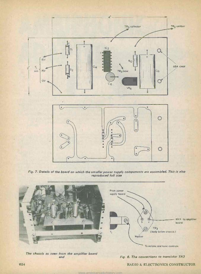
2" TI
15V
D
jj02 sec. 15V
+
OV
TR3 collector
IC2
C15
o
TR3 emitter
6BA clear
Fig. 7. Details of the board on which the smaller power supply components are assembled. This is also reproduced full size
% /i/, %// /
The chassis as seen from the amplifier board end
From power supply board
TI
16V+ to amplifie I b e / board
\\ ®i / TR3
(body below chassis ) / Washer
To volume and tone controls
Fig. 8. The connections to transistor TR3
624 RADIO & ELECTRONICS CONSTRUCTOR
www.americanradiohistory.com

To Cg
TREBLE Cs
BASS
OPIIMelling" RIO
VR5 VR4
Chassis connection to VR3a
VOLUME
From C4
VR3
To chassis tag at T1
Fig. 9. The wiring of the components in the volume and tone control network for one channel. The other channel is connected up in
the same manner
The remaining components are wired directly to the volume and tone controls in the manner illustrated in Fig. 9. This shows the wiring for the left rear channel only, the wiring for the right rear channel being essen- tially the same. The wiring is quite straightforward and should present no problems.
The interconnecting wiring between the two boards and to the volume and tone control networks may now be completed. The connections to the input socket and speaker sockets may also be wired in, the requisite chassis connections being made at the sockets themselves. The non -earthy left and right hand inputs are connected to two pins of the 5 -way DIN socket. None of the a.f. wiring needs to be screened but the leads should be kept reasonably short and direct.
When all the wiring has been completed, the two printed boards may be finally mounted on the chassis. Next, after a careful visual check for wiring errors, connect a testmeter switched to a suitable volts range between the emitter of TR3 and chassis, switch the adapter on and adjust VR6 for a reading of 16 volts in the meter.
ADJUSTMENT Ideally, the adapter shold be fed from the `Tape'
or 'Aux' output of the stereo amplifier, and any such output that will provide 100mV or more into about 2Okci is suitable. In case of doubt, the availability of a suitable output can be checked from the manufac- turer's literature for the amplifier. It is regretted that, owing to the very wide range of stereo equipment which is currently available, it is impossible foir the writer or the staff of this journal to advise on the out- put facilities offered by any particular make and model of stereo amplifier. In the absence of a low level output it is, in any case, possible to obtain a suitable input for the adapter from the amplifier speaker ter- minals; and the procedure required here is discussed later.
VR1 and VR2 must be adjusted to ensure that the adapter is not overloaded and also to provide balanc- ed inputs. Connect the unit to the stereo amplifier by way of screened leads and plug an 8S2 speaker into each of the adapter output sockets. Set VR1 and VR2 to a roughly central setting and switch the adapter on.
Put the volume controls VR3 and VR3a at max- imum then, keeping VR1 and VR2 approximately in step, adjust these so that it is possible to obtain full
output from the adapter without major overloading occurring on volume peaks. Note that VR2 is adjusted in an anti -clockwise direction to increase volume, whereas VR1 is adjusted in a clockwise direction for increased volume.
The inputs are then balanced by playing a mono programme or recording through the system. Either VR1 or VR2 is then adjusted for minimum output from the rear speakers. If the input to the adapter is taken from the speaker outputs of the stereo amplifier, it is absolutely essential that the balance control of the amplifier be set correctly before the in- puts to the adapter are balanced.
Once the input balancing procedure has been carried out, the adapter may be switched off and the outer casing screwed on. The adapter is then ready for use.
SPEAKER PHASING In order to obtain the best results from the adapter
it is essential that the rear speakers have correct phas- ing. The two front speakers need the same phasing as for ordinary two channel stereo reproduction, and so will already be correct in this respect.
If the rear speakers are obtained as a stereo pair they should be connected with the same polarity to their plugs. Therefore, provided the two adapter speaker sockets are wired with the same polarity (i.e both flat connectors or both round connectors wired to chassis) of the two possible way's of connecting the rear speakers, one must be correct. The phasing of the speakers can be altered by, transposing their connec- tions but, since the outputs of the adapter are in anti - phase, a much simpler method consists of simply changing over the speaker plugs in the two adapter speaker sockets. Should this result in what has been referred to in this article up to now as the left rear socket feeding the right rear speaker, and vice versa, all that has to be remembered is that the upper volume and tone controls now apply to right rear instead of to left rear.
When the speaker phasing is correct sounds from the two left hand speakers should blend well together, as should those from the two right hand speakers. When the phasing is incorrect diagonally opposite speakers will blend well together, and this will result in much of the sound seeming to originate from just above the listener's head. A little experiment should
TR3 is mounted under the chassis, which func- tions as a heatsink
MAY 1976 625
www.americanradiohistory.com

soon reveal the correct method of connection for the rear speakers.
Since the front speakers are reproducing sounds which would come from relatively low down in a con- cert hall, and the rear speakers are producing sounds which would normally come from comparatively high up, the system will usually sound most convincing with the front speakers on the floor and the rear speakers elevated above head height. This gives a form of three-dimensional sound reproduction.
Improved performance may also be obtained by turn- ing the rear speakers to face the rear wall of the room. The purpose of this is to diffuse the ambience. As treble frequencies tend to be lost during the process of being reflected around a hall to a greater extent than middle and bass frequencies, greater realism may be given by introducing a certain level of treble cut to the rear channels. There is plenty of scope for experiment here, and it is largely a matter of individual taste as tc what is considered to produce the most acceptable results.
SPEAKER OUTPUTS If the stereo amplifier is not fitted with a `Tape' or
'Aux' socket which can be coupled direct to the adapter, the adapter inputs can, as already men- tioned, be taken from the speaker outputs of the stereo amplifier. It is necessary to provide input attenuators as, otherwise, it will be very difficult to set up VR1 and VR2.
When .the stereo amplifier outputs both have one terminal connected to chassis, the requisite attenuators required are as illustrated in Fig. 10(a). The non -earthy terminal of each stereo amplifier speaker output connects to the upper end of the 39k û resistor in each attenuator.
If the stereo amplifier speaker outputs do not have 9ne terminal at chassis- potential, additional 112F capacitors are added, as in Fig. 10(b). These capacitors block any direct voltages which may be present at the stereo amplifier speaker outputs. The attenuator components of Figs. 10(a) or (b) may be mounted inside the adapter on a small tagstrip positioned near the 5 -way DIN socket.
FINAL POINTS It is not really necessary to have rear speakers of
equal .quality to those employed for the front channels. The author, for instance, found results were perfectly satisfactory when using two-way speaker
Sterco L.H.output
39kn
Ikn
To VRI To VR2
All resistors 1/4 watt 10%
To non -earthy L.H. output terminal
Ti
kn
lk To VR1
(a)
39kn
Ikn
To non -earthy R.H.
output terminal
(b)
Stereo R.H. output
Amplifier chassis
IyF
39kn
lk To VR2
Ikn
17 Amplifier chassis
Fig. 10(a). If necessary, the left and right hand inputs for the adapter may be obtained from the stereo amplifier speaker outputs. Attenuators are required in each channel, as shown here (b). Should the stereo amplifier outputs not have one terminal connected to chassis, isolating capacitors are added to block
any direct voltages which may be present
systems at the front and dual cone speakers at the rear.
Apart from adding ambience to material produced in a concert hall, the ambiphonic system can make an improvement to the effectiveness of other types of music. A great deal of pop music is embellished with special phasing effects and, as might be expected, these can produce very interesting results when played over equipment of the type which has been described in these two articles.
(Concluded)
BACK NUMBERS For the benefit of new readers we would draw attention to our back number service.
We retain past Issues for a period of two years and we can, occasionally, supply copies more than two years old. The cost is the cover price stated on the issue, plus 11 p postage.
Before undertaking any constructional project described in a back issue, it must be borne in mind that components readily available at the time of publication may no longer be so.
We regret that we are unable to supply photo copies of articles where an issue is not available. Libraries and members of local radio clubs can often be very helpful where an issue is not available for sale.
626 RADIO & ELECTRONICS CONSTRUCTOR
www.americanradiohistory.com
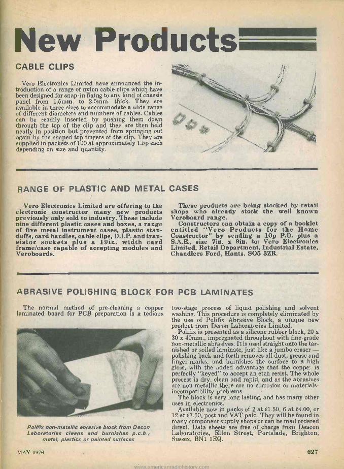
New Products CABLE CLIPS
Vero Electronics Limited have announced the in- troduction of a range of nylon cable clips which have been designed for snap -in fixing to any kind of chassis panel from 1.5mm. to 2.5mm. thick. They are available in three sizes to accommodate a wide range of different diameters and numbers of cables. Cables can be readily inserted by pushing them down through the top of the clip and they are then held neatly in position but prevented from springing out again by the shaped top fingers of the clip. They are supplied in packets of 100 at approximately 1.5p each depending on size and quantity.
RANGE OF PLASTIC AND METAL CASES
Vero Electronics Limited are offering to the electronic constructor many new products previously only sold to industry. These include nine different plastic cases and boxes, a range of five metal instrument cases, plastic stan- doffs, card handles, cable clips, D.I.P. and tran- sistor sockets plus a 19in. width card frame/case capable of accepting modules and Veroboards.
These products are being stocked by retail shops who already stock the well known Veroboard range.
Constructors can obtain a copy of a booklet entitled "Vero Products for the Home Constructor" by sending a 10p P.O. plus a S.A.E., size 7in. x gin. to: Vero Electronics Limited, Retail Department, Industrial Estate, Chandlers Ford, Hants. SO5 3ZR.
ABRASIVE POLISHING BLOCK FOR PCB LAMINATES
The normal method of pre -cleaning a copper laminated board for PCB preparation is a tedious
Polifix non-metallic abrasive block from Decon Laboratories cleans and burnishes p.c.b.,
metal, plastics or painted surfaces
two -stage process of liquid polishing and solvent washing. This procedure is completely eliminated by the use of Polifix Abrasive Block, a unique new product from Decon Laboratories Limited.
Polifix is presented as a silicone rubber block, 20 x 30 x 40mm., impregnated throughout with fine -grade non-metallic abrasives. It is used straight onto the tar- nished or soiled laminate, just like a jumbo eraser - polishing back and forth removes all dust, grease and finger -marks, and burnishes the surface to a high gloss, with the added advantage that the copper is perfectly "keyed" to accept an etch resist. The whole process is dry, clean and rapid, and as the abrasives are non-metallic there are no corrosion or materials - incompatibility problems. -
The block is very long lasting, and has many other uses in electronics.
Available now in packs of 2 at £1.50, 6 at £4.00, or 12 at £7.50, post and VAT paid. They will be found in many component supply shops or can be mail ordered direct. Data sheets are free of charge from Deacon Laboratories, Ellen Street, Portslade, Brighton, Sussex, BN1 1EQ.
MAY 1976 627
www.americanradiohistory.com

ADD-ON VU
A simple design which enables the out- put of an f.m. turner or the signal level in an a.f: amplifier to be monitored in terms
of volume units.
When making recordings from the radio it is not easy to find the correct settings for the recording level control or controls without some indication of the modulation level being used at the transmitter. This is because the transmitter is lightly modulated for most. of the time, with the modulation level only ap- proaching 100% on occasional crescendos.
By fitting a VU meter (volume units meter) to the tuner it would be possible to adjust the recording level meter or meters to match the reading on the VU meter, and so ensure that the correct recording level is used. Unfortunately, though, few tuners are fitted with a VU meter.
The VU meter which forms the basis of this article can prove to be a very worth -while addition when making recordings. The device is constructed as a self- contained add-on unit, and so it is not necessary to make any connections to the tuner before connecting the meter to it. The meter may also, of course, be employed for indicating volume units in applications other than at the output of a tuner. It is housed in a ready made aluminium case which measures ap- proximately 4 by 21- by 1 fin. It is battery powered, and its low current consumption of about 2.2mA only from a PP3 battery ensures economy of operation.
R.M.S. OR PEAK READING? There are two types of VU meter, namely the r.m.s.
and peak reading types. As one might expect, the r.m.s. type indicates the relative r.m.s. level of the signal, while a peak reading type has a fast attack and a slow decay, so that the meter shows the relative peak level of the signal. Whilst it is true that the peak reading meter has certain advantages over the r.m.s. type, this circuit is for an r.m.s. meter. Most recorders are fitted with an r.m.s. recording level meter, and it is an obvious advantage to have the same type of meter as is fitted to the recorder.
COMPONENTS
Resistors (All fixed values ; watt 10%)
R1 4.7k t2 R2 l k S2
R3 15k S2
R4 560k R5 2.2kû R6 2.7k S2
VR1 500kí2 pre-set potentiometer, miniature horizontal 0.1 watt (see text)
Capacitors Cl 4.7 or 5jtF electrolytic, 10V Wkg. C2 16µF electrolytic, 10V Wkg. C3 47 or 50igF electrolytic, 6V Wkg. C4 161CF electrolytic, 10V Wkg.
Transistors TRI BC109 TR2 BC109
Meter M1 VU meter, 59 x 46 x 35mm. (see text)
Switch S1(a)(b) d.p.d.t. slide switch with centre "off" (see
text)
Miscellaneous Aluminium box type AB9, 4 x 2i x lfin. 9 volt battery type PP3 (Every Ready) Battery connector Veroboard, 0.lin. matrix Stereo screened lead Grommet, nuts, bolts, etc.
828 RADIO & ELECTRONICS CONSTRUCTOR
www.americanradiohistory.com

METER
By P. R. Arthur
THE CIRCUIT The complete circuit diagram of the add-on VU
meter is shown in Fig. 1, and it consists basically of a two transistor amplifier feeding the VU meter move- ment. The meter movement has an integral rectifier circuit and a series resistor. It is calibrated to take into account the non -linearity of its rectifier circuit and so no overall negative feedback is applied as would be necessary with an ordinary a.c. millivoltmeter.
As the output from most tuners is at a fairly high level, say about 200 to 600mV, and the meter requires about 1.2 volts for a reading at the zerd reference level, the amplifier does not need a very high voltage
VR1
C
BCIO9 Lead -outs
R4
Fig. 1. The circuit of the VU meter. A simple two transistor amplifier with controlled voltage
gain is incorporated
gain. On the other hand, if inaccuracies are to be avoided it must have a flat frequency response over the audio frequency spectrum and offer low distor- tion. Also, if the supply voltage is unstabilized, it must have a gain which is virtually unaffected by variations in supply potential. A further requirement is a reasonably high input impedance, so that the VU meter places a minimum of loading on the equipment to which it is coupled. All these factors are achieved in the present circuit, which incorporates an amplifier having a high level of negative feedback.
Referring to Fig. 1, both transistors are in the com- mon emitter mode, and the signal at the collector of TRl is directly coupled to the base of TR2. R1 is the collector load resistor for TRl, and R5 the collector load for TR2. R6 is the emitter bias resistor for TR2, with C3 as its bypass capacitor.
The emitter of TR1 is connected to a potential divider, R3, R2, between TR2 collector and the negative rail. This provides the required negative feedback, and the values of R2 and R3 decide the voltage gain of the amplifier. This is given ap- proximately by the sum of R2 and R3 divided by R2. The voltage gain, in consequence, is approximately 16 times.
VR1 functions as a sensitivity control. Cl and C4 are input and output d.c. blocking capacitors respec- tively, whilst C2 is the supply bypass capacitor. R4 is
\\R ' y
All the components appear at the rear of the front panel
MAY 1976 829
www.americanradiohistory.com

The Veroboard panel is mounted between the meter movement and the slide switch
the base bias resistor for TR1, being returned to the emitter of TR2. This bias circuit is very stable due to the high level of d.c. feedback employed.
S1 is a d.p.d.t. slide switch having a central off posi- tion. One pole of this connects either the left hand or the right hand channel to the input of the device. The other pole is used to switch the positive supply. The author obtained both this switch and the VU meter movement from M. Dziubas, 158 Bradshawgate, Bolton, BL2 1BA.
The meter movement has dimensions of 59 by 46 by 35mm., and is referred to as a "59mm. VU meter".
CASE DRILLING The case in which the unit is housed is an
aluminium box type AB9. This has a removable lid which is used as the front panel. The drilling and cut- ting out required for this panel are shown in Fig. 2.'
The large cut-outs for the meter and S1 can be made with a fretsaw or coping saw, preferably one fitted with a fine toothed blade. The smaller mounting holes for these two items are made with a No. 31 twist drill, and their positions can be located with the aid of the meter and switch after the large cut-outs have been made. A solder tag is fitted under the lower left mounting nut of the meter, as seen from the rear. The hole for the input cable is fitted with a grommet.
1/2
11/4*
23/4`
H6°dia
Wet
6BA clear
Fig. 2. The holes required in the front panel. The 4in. and 21in. dimensions are nominal
ELECTRICAL ASSEMBLY The small components are mounted on a Veroboard
panel of 0.1in. hole matrix having 20 by 10 holes. There are no breaks in the copper strips, which run lengthwise.
The component layout on the panel is illustrated in Fig. 3. From this it will be seen that VR1 is a miniature horizontal skeleton pre-set potentiometer having 0.2in. spacing between its track tags, and 0.4in. spacing between the slider tag and a line drawn between the track tags. All the fixed resistors and capacitors are mounted vertically. Because of this it would be advantageous to employ printed circuit type capacitors, with both lead -outs at one end of the body. This is not essential, however, and capacitors with ax- ial lead -outs can alternatively be employed, one lead - out being bent down to run alongside the capacitor body.
Fig. 3 also shows the wiring external to the Veroboard. As can be seen from the accompanying photographs, the board is positioned between S1 and the meter. There are two leads from the board to Sl, and another two leads from the board to the meter. These consist of a heavy gauge single strand wire (around 16 s.w.g.) covered with sleeving, and they provide the mounting for the Veroboard. The four leads should be kept as short as possible. They should be soldered to the appropriate points on the board after all the other components have been fitted, and should initially be cut to a more than adequate length. They are then cut to the required length just before soldering to S1 and the meter.
The input lead is stereo screened cable with the braiding connected to the earthy meter tag. Its length can be as required and its free end is terminated in a plug or plugs to suit the particular equipment with which the unit is to be used.
There is space for the PP3 battery below the meter. Some foam rubber or plastic may be glued to the in- side rear of the case to hold the battery in position when the lid is screwed on.
SETTING UP
The VU meter unit is connected to the equipment being monitored in the most convenient manner available. If the equipment is a tuner having only a single ouput socket, the unit will need to be connected to a single plug in parallel with the recorder input. However, some tuners have additional outputs mark- ed as "Tape", "Aux.", etc., and one of these, if not in use, will probably prove to be suitable.
The only adjustment needed is the setting up of the sensitivity control, VR1. A convenient approach con- sists of taking advantage of the B.B.C. test transmissions which are sent out from Radio 3 stereo transmitters after the close of programmes on Mon- day and Saturday evenings. The first test consists of a 250Hz tone in the left hand channel and a 440Hz tone in the right hand channel, each at 40% of maximum modulation prior to pre -emphasis at the transmitter. VR1 is first set to minimum sensitivity (slider fully anti -clockwise) and, with the test transmission ac- curately tuned in, is adjusted to give a reading of 40% in the meter on either channel. The subsequent tests in the transmission are ignored. Since all B.B.C. transmitters operate to the same standard and since limiting action in conventional f.m. receivers should produce the same audio level for any reasonably
830 RADIO & ELECTRONICS CONSTRUCTOR
www.americanradiohistory.com

Input
O 0 0
o
O 0 0
O 0 o 41;l
'o
o 0 o o
R4o 0 0 0
o o p
o 0 0 0
Solder tag
Battery clip
O 0 0 0 0 0 0 0 0 0 0
c R3 o o o o o o 0 o o
c b } o0 0 0 0 0
I/ o TR2 00C4 o o o 0 C
0 0 0 0
0 0 0 0
C3o 0 0 0
0 0 0 0 0
0 0 0r/ Direction of copper strips
Fig. 3. Layout of components on the Veroboard panel. Also shown is the wiring outside the panel
strong signal, the adjustment will hold good on other B.B.C. stations.
Most stereo decoders have outputs which are close- ly matched and so, with the unit calibrated for one channel, it should be accurate on the other channel. If there should happen to be a marked discrepancy, then a 100kí2 pre-set variable resistor can be connected between the input lead for the channel with the greater output and the appropriate tag on Si. The variable resistor may be positioned inside the unit. The unit is then set up on the channel with the lower output, after which the additional pre-set resistor is
Another view of the interior of the unit
adjusted to give the same reading on the other channel.
OTHER USES
If desired, the VU meter unit may be built in a mono version. In this case a single screened input wire is required, this connecting direct to VR1. The 3 -way slide switch is replaced by a standard slide switch connected in the positive supply circuit, and which merely functions as an on -off switch.
Another use would be as a VU recording level meter for a tape recorder fitted with a less satisfactory form of level indicator, such as a miniature moving -coil meter or a Magic Eye. In these instances the input to the unit can be taken from a suitable point in the recorder amplifier, probably at the point which feeds the existing indicator circuit. The unit must not be employed with any mains powered equipment which is not fully isolated from the mains supply by a double -wound mains transformer.
If the unit is used as a recording level meter, VR1 is adjusted to read zero VU when the level indicator on the recorder registers the maximum permissable recording level.
No means of measuring the battery voltage is incor- porated. The current consumption of the unit is so small that, with normal use, the battery can simply be replaced at about three month intervals.
EDITOR'S NOTE The outputs of some f.m. tuners contain a small
level of the 19kHz pilot tone and its harmonics. No filters are provided in the simple circuit described here and the pilot tone, if present at sufficient strength, could cause inaccuracies at low VU readings, although comparable readings will still be given. This point does not arise when the VU meter is used in other applications.
MAY 1976 631
www.americanradiohistory.com
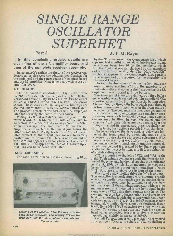
SINGLE RANGE OSCILLATOR S UPERHET
Part 2
In this concluding article, details are given first of the a.f. amplifier board and then of the complete receiver assembly.
In last month's article the circuit of the receiver was described, as also were the winding modifications for the aerial coil and the construction of the mixer board and the i.f. amplifier. Next to be dealt with is the a.f. amplifier board. A.F. BOARD
The, a.f. board is illustrated in Fig. 8. The com- ponents are assembled on a piece of plain 0.15in. Veroboard having 10 by 19 holes. First, two holes are drilled out 6BA clear to take the two 6BA screws shown. These screws are lin. long and solder tags are secured under their nuts in the manner illustrated. The projecting parts of the screws will be employed later for securing the board to the chassis.
Wiring is carried out in the same way as for the mixer board. All leads on the underside should be kept close to the board and sleeving shiiuld be fitted where necessary. The lead from R13 in the i.f. amplifier is connected to the board just before the latter is mounted. Flying leads from the a.f. board later connect to the output jack socket; to battery positive and to S2 and VR1. R14 is not mounted on the board but appears externally between the slider of VR1 and C9. The appropriate lead of C9 is bent up so that R14 can be soldered to it later.
CASE ASSEMBLY The case is a "Universal Chassis" measuring 10 by
Looking at the receiver from the rear with the back panel removed. The battery fits on the shelf between the i.f. amplifier assembly and
the case side
By F. G. Rayer 6 by 4in. This is shown in the Components List (which appeared last month) broken down into its constituent parts, these being two 10 By 4in. members, which form the front and rear panels, two 6 by 4in. members and a 10 by 6in. metal plate. The "Hardware Kit" which also appears in the Components List, consists of the screws and nuts required for the assembly of a "Universal Chassis".
The two 6 by 4in. sides go outside the front and rear panels, thereby enabling a 10 by Sin. member to be fitted internally and act as a shelf supporting the i.f. amplifier, the a.f. board and the battery.
The front panel should be drilled out first before any assembly work is carried out. The spindle of VC2 is positioned centrally, l in. up from the bottom edge. It is mounted by three 4BA bolts which pass through the front panel into tapped holes in the front plate of the capacitor. The bolt ends must not pass beyond the front plate or they may damage the capacitor vanes. In consequence the bolts should be short, and spacing washers may be fitted between the panel and the capacitor front plate. Holes are also required for the tuning drive and its cursor, and these are drilled ac- cording to the instructions provided with the drive.
The lower edge of the drive scale is below the bot- tom of the front panel by about in. and so it is necessary to raise the case to provide clearance. With the prototype a strip of wood 10 bye by ein. was af- fixed under the front panel. An alternative approach, which may be used if a second 10 by6M. metal plate is attached to the case bottom, is to t four rubber feet of suitable dimensions.
VC1 is mounted to the left of VC2 and VR1 to the right. Their spindle centres are both tin. from the bot- tom of the panel and horizontal spacing is as indicated in Fig. 9. Slide switch Sl is mounted immediately below VC1, and the output jack immediately below VR1. Both are ein. above the bottom of the panel.
The use of a slow motion drive for VC1 is optional. This capacitor is manufactured with a normal spindle or with a spindle incorporating a slow motion drive, although the latter may be difficult to obtain from retail sources. If the standard capacitor without slow motion is used it is mounted to the front panel in the same way as VC2 using three countersunk bolts. The slow motion type has a longer spindle and can be set back by mounting it with tin. countersunk bolts, each with two nuts, as in Fig. 9. If a 365pF capacitor with integral slow motion drive cannot be obtained, Home Radio list a 208+176pF capacitor type "00" with slow motion. This could be used instead with both sets of fixed vanes connected together to give a maximum capacitance slightly in excess of 365pF.
A small Perspex cursor with a radial line scratched on it can be affixed to the shaft of VC1 by drilling a
832 RADIO & ELECTRONICS CONSTRUCTOR
www.americanradiohistory.com

Cc
R14
52,1/R1
o Y o
o
lI 0 R16
o o o
o
6BA bolts
R17 o o o o
o o o 0
o
o
o o o o
o 0 0 0
0 o R16 o
R15 c
o o o
+
TR6
R18
o
Ì
R19 o
20
TR7 0
o o o o
0 o o o 0 0
+ o o
o
o C O CI I
o
R18
mc -chassis connection
o
Fig. 8. The component and wiring sides of the a.f. amplifier board
hole in it for a grommet which is a tight fit on the shaft (the slow rotating shaft with the slow motion version). A 14in. diameter scale is fitted to ,the panel behind the cursor.
A rectagular slot can be made for S1 by drilling a few small holes close together then finishing with a small file. The holes for VR1 and the output jack may also be drilled.
The two side pieces may now be secured to the front panel. The left hand side piece requires two small holes for insulated aerial sockets, these being near the position to be taken up by VC1. It also has an in- sulated mounting, which may be home -constructed from plastic clips or similar, for the telescopic aerial. The aerial can be any type having an extended length of 30in. or more. Further required on the left hand side member is a hole for an earth socket.
The 10 by Sin. chassis member which forms the in- ternal shelf is next fitted between the two side pieces. This takes up the position shown in the photographs and should be set back sufficiently to clear the mixer board. The i.f. amplifier will be mounted on this shelf by two 4BA bolts and nuts with its Veroboard compo- nent panel to the front. There should be room on its
TK1
Battery +
R13
right hand side for the a.f. board. Three holes are needed in the shelf immediately below the i.f. trans- formers to allow access to their cores.
The a.f. board will be fitted to the shelf with C9 at the front. Extra nuts on its two 6BA bolts give clearance from the shelf. The two 6BA clear holes needed in the shelf may now be drilled.
INTERCONNECTIONS Assembly is simplified if the rear panel is not fitted
until later. The front panel components may next be fitted. The lead from the aerial coil to VC1 fixed vanes, and the leads to VC1 moving vanes and Si may now be connected. The i.f. panel is next fitted, the leads from the mixer board to IFTI and the positive supply being connected. These two leads pass through the hole in the shelf under IFTI. Finally, the a.f. board is mounted, this taking up the positive supply lead from the i.f. amplifier.
Fig. 9 shows the interconnections between sections. The two output leads from the a.f. board pass under the board to the jack socket. R14 is connected between the slider of VR1 and C9, and the other wir- ing to VR1 and S2 is completed as shown. The battery
MAY 1976 633
www.americanradiohistory.com

1Óíc3`
Battery
Al 4
TC1
2
WTI
R13 DI
A.F. amp. board
R1
Mixer board
IFT2
11
Is
i 1
Ì 11
ii 11.
VC'
31/4"
VC2
31/4,
Fig. 9. Illustrating the interconnections between the sections of the receiver
connectors should be insulated or taped so that they cannot short-circuit to the case metalwork.
The lead from pin 9 of the aerial coil on the mixer board is taken to one of the insulated aerial sockets, this corresponding to socket Al in Fig 1 (published last month). Trimmer TC1 connects between the left hand fixed vane tag of VC1 and the remaining aerial socket, which now becomes socket A2. The earth socket can be connected to any convenient chassis point.
The rear panel can be fitted when wiring is com- pleted, or left until the receiver has been tested. The same applies to the case top, which is secured with self -tapping screws. There is no real need to enclose the bottom of the case, but another 10 by 6in. metal plate can be used here, if desired. AERIALS
The telescopic aerial will give reception without the need for an external aerial -earth system. A short length of flexible wire connected to the telescopic aerial is terminated in a plug which can be fitted to socket A2, or removed if a wire aerial is to be plugged in here.
An external aerial is normally plugged into socket Al, but it may instead employ the A2 socket if it is not very long. A long aerial at this socket will cause VC1 tuning to be very flat unless TC1 is set to nearly minimum capacitance. The effects of aerial loading will soon become clear. In general a loose coupling, with the aerial at socket Al or at A2 with TC1 giving a low capacitance, should be used if this gives enough signal strength.
When an earth connection is available it can be ex- pected to increase the volume of weak signals.
ADJUSTMENTS The oscillator coverage should be suitable if the
6BA core screw of L7 has 15 threads projecting, but it can be modified by screwing the core in or out. This will have considerable influence on the receiver coverage given by VC2.
A small adjustment of some of the i.f. transformer cores may be needed for the best possible results. 'i'he adjustments should be made with a correct trimming tool, such as the Denco type TT5, or the cores may break. Carefully tune in a stable signal, preferably one which gives a low output volume with VR1 well advanced (the aerial can be removed to provide this) and turn each core a little one way or the other for best volume.
It will be found that some short wave signals can be received with VC2 at two widely separate settings. This arises from the way in which the circuit operates, as was described last month. But on the l.f. band the oscillator frequency is above the signal frequency at all times.
Any loudspeaker from 81D to 75í1 may be used, an impedance of 150 giving best results. Battery drain is lower with a high speaker impedance. With headphones, the falling off in volume encountered with higher impedance speakers is not of importance, and phones of up to 5000 to 2ki2 will operate satisfac- torily. A full headset is recommended and not a single earpiece. Crystal earphones cannot be used.
A PP9 battery is suitable. Current consumption is around 8mA with no signal tuned in or when operating at low volume. Current peaks of 20 to 40mA occur when operating a 15o loudspeaker at ample volume.
(Concluded) 634 RADIO & ELECTRONICS CONSTRUCTOR
www.americanradiohistory.com
.n.. .._.. 0 000
Du r
This month Smithy the Serviceman takes his assistant on a tour of some of the more illogical pre - metrication units of length. But this provides only a
background to their main discussion: a review of the latest hints received
readers. "Ah well," said Smithy cheerfully,
"I've got an exceedingly technical job to do when I pet home this evening."
He raised his disgraceful tin mug to his lips and drank deeply. The crumbs around his feet gave evidence of the lunch he had just consumed. His assis- tant, busily engaged in eating an apple, looked up at him and swallowed.
"Oh yes," he said. "And what's that?"
"I'm adding an extension to our front door bell," replied Smithy. "I can never hear the darned thing if I'm working out in the back."
"Blimey," remarked Dick. "You'll need a circuit diagram and instruc- tions for a project like that."
I think Ill get by," chuckled Smithy. "However, you could do me a favour when we start work again. There's a drum of cheap low voltage twin flex in the spares cupboard and perhaps you could measure off a length of it for me."
"Okeydoke," replied Dick equably, as he took a last bite at his apple.
READERS' HINTS Taking câreful aim, Dick threw the
apple core into the waste bin at the end of the Workshop. There was a metallic clang as it hit the side of the bin, then a rustling noise as it settled down into the debris inside.
"I wish you'd put things like that in
the dustbin outside," complained Smithy. "They encourage mice."
"Mice don't eat apples," retorted Dick. "And in any case, I don't leave half as much mess around me when I eat my lunch as you do. Look at all those crumbs around you. There's enough solid food there to provision a whole regiment of mice. How long do you want it?"
"Want what?" "This bit of flex." "Oh, that. I measured it out last
night and I'll need exactly 20 metres." "Metres?" snorted Dick in disgust.
"Why didn't you do it in yards? I'm just about fed up to the teeth with the way everybody's measuring things in metres these days. Grams too, come to think of it."
"Well," remarked Smithy mildly. "We are supposed to have goné over to metrication you know."
"I was always brought up stated
Dick firmly, "to measure things in good and trusty English units. Couldn't you have thought of any units other than metres?"
"I suppose so," said Smithy thoughtfully. "Instead of 20 metres, I could for instance have said 20 million microns. Or even two hundred thou- sand million Angstroms."
Dick glowered at the Serviceman. "Trust you," he said irritably, "to
make it more complicated. What I mean is, can't you express that length in proper English units?"
"All right,' said Smithy. "I'll see if I can can do a conversion figure for you."
He put down his mug and pulled his note -pad towards him. There was silence for some moments as he scribbled out a calculation. With a grunt of satisfaction he underlined a final number and put his pen down again.
"Well," said Dick impatiently,` "what does it come to?"
"That length of 20 metres," stated Smithy happily, "is equal to 3.98 rods!"
"3.98 what?" "3.98 rods," replied Smithy. "Or, if
you like, 3.98 poles or 3.98 perches." "Ye gods," complained Dick. "I've
never met anyone with a brain as devious as yours is."
"All right," chuckled Smithy. "I'll work it out properly for you in a mo- ment. But, in the meantime, there's something else I'd like to mention."
"What's that." "It's the fact that we are just about
due for another session on readers' hints. Quite a few have come in since the last time."
"Have they?" asked Dick, forgetting his annoyance with the Serviceman's predilection for unusual units of length. How about having a go at them right
now?" "That," remarked Smithy, opening
a drawer in his bench and taking out a sheaf of letters, "is precisely what I in- tend to do."
Dick settled himself expectantly on
his stool as Smithy took up the top letter and read it carefully.
"Now here," he remarked, "is a good one for starters. Our correspon- dent says that surplus and bargain offers of power transistors practically never include insulating sets for moun- ting on a heatsink. If, however, you're prepared to spend a little time at it, it's pretty easy to make up one's own in- sulating sets using mica obtained from an old electric iron element." (Fig. 1
(a).) "I see," said Dick pensively. "That
sounds all right, but my own ex- perience has been that mica is rather difficult stuff to handle."
"It is a little," admitted Smithy. "This letter says that the wastage rate in making the mica washers is high, and that the best tool for cutting it is a sharp pointed modelling knife with the mica placed on a flat metal surface. The mica can be cut out to cover a slightly larger area than the manufac- tured type would, and it doesn't have to look quite as neat. The holes for the lead -outs and mounting bolts can be cut out with the modelling knife, too. Using a drill to make the holes should never be attempted unless the mica is at least a sixteenth of an inch thick."
"What about the insulating bushes?"
"Pieces of plastic insulation taken from 15 amp power cable can be used here," said Smithy. "If you strip off this insulation you get what is effec- tively thick-walled sleeving."
"Wait a minute," said Dick, frow- ning. "There seems to be a snag here. Ah, yes, I've got it! The ordinary manufactured insulating bushes have a flange which ensures that the moun- ting nuts or the solder tag which con- nects to the transistor collector, cannot short to the heatsink. You can't have flanges if the insulating bushes consist of plastic sleeving."
"No problem," replied Smithy shortly. "You just use s.r.b.p. in- sulating washers. Or you can use another idea that's referred to in the letter. This is to cut out a narrow rec- tangle of printed circuit board and drill two holes in it to take the tran- sistor mounting screws. This is fitted under the securing nuts with the copper side outwards, whereupon you connect to the. collector by simply soldering a wire to the copper." (Fig. 1(b).)
DRILLING TIN-PLATE "Stap me," said Dick, impressed.
"That's a crafty scheme." "It is, isn't it. " replied Smithy, put-
ting the letter down and picking up his mug.
He drank noisily, then took up a se- cond letter.
"Here," he resumed, "is one of those simple dodges which always turn out to he so useful in practice. This letter states that, when drilling,large holes in thin tin-plate for switches and control hushes, it often happens that the drill becomes jammed in the hole. The metal then gets distorted, and j the
MAY 1976 635
www.americanradiohistory.com

6BA washer
Mica_
Solder tag' Insulated washer
Fig. 1(a). Using a home- made insulating set for mounting a power tran- sistor. Note that a 68A washer is employed in con- junction with an 8BA screw (b). A narrow rectangle of printed circuit hoard with the copper on the outside may be used in place of the insulated washers. This also enables a connection to be made to the transistor
collector
'result is that the hole has to be finished off with a round file."
"I've bumped into that sort of thing quite often," remarked Dick. "Thin ti:i-plate_can be pretty vicious stuff at times."
"True," agreed Smithy. "Well, 'the difficulty can be overcome by first drilling a small hole, say an eighth of an inch in diameter, aad then using a countersinking tool. This gives a neat round hole without any burrs or distor- tion of the metal. During the counter- sinking process, the tin-plate is sup- ported on a wood block with a small hole drilled in it to match the initial small hole in the tin-plate. The writer of the letter says that he has employed this method many times on 2 ounce tobacco tins used for pre -amplifiers, converters and similar small items."
Smithy put down the letter, picked up his mug and drained its contents. After this; he held up the mug in front of him. Dick rose wordlessly, took the mug from him and carried it over to the variegated array of utensils ranged alongside the Workshop sink. Established over many years, the Workshop Tea Ritual was now so automatic as to be beyond comment on the part of either Dick or Smithy. As Dick returned with the filled mugg, he was surprised to find Smithy scribbling some figures in his note -pad.
"Hello," said Dick, "don't say that the next hint has got something in it that needs working out."
(a)
Power transistor
Heatsink
Copper clad laminate
(b)
Solder joint on
copper foil
LAMINATE CUTTER Smithy took up another letter and
glanced through it. "Now I've got a really good hint
here," he said. "I'll read out what the letter says. 'Recently I had to cut a piece of Veroboard into a number of different sized parts, and got together my junior hacksaw and fle. Then I had a different idea. I fished out my Mason -Master Blue Flash tungsten - carbide tipped laminate cutter, and tried a few strokes on a scrappiece of board. The result delighted me. My procedure now is to mark the cuts I require with a blue nylon -tip pen on both sides of the Veroboard, then cut down on both sides. The laminate cutter tip makes a V -cut of about 60 degrees, and it is soon quite easy to snap the board through. A quick wipe with the file removes any rough edges, and the fact that the tool cuts the sur- face layers ensures that there is no flaking of the surface, which can easily be given with the hacksaw. I use a steel rule as a guide straight -edge, and the result has a really professional finish."
Smithy placed the letter on his bench and indicated several sketches in it to his assistant. (Fig. 3(a).)
Dick looked a little blank. "I'm not quite sure," he said reluc-
tantly, "what a laminate cutter is." "To be quite frank," confessed
Smithy cheerfully, "I wasn't too cer-
tain myself. So I popped round to my friendly neighbourhood ironmonger's and bought a Mason -Master laminate cutter for myself to try out. It's only about 50 pence in price and it certainly does the job."
"Have you got it here now?" "Yes," said Smithy, reaching to the
back of his bench. He picked up a small rectangular blue plastic case with a transparent front and passed it over to Dick. "There you are. It comes complete with instructions for cutting ordinary laminate. If you like, you can try it out on some odd bits of Veroboard when we've finished this session. You need to practice a few times to get the hang of it before you start using the cutter for a serious job."
Dick pulled the cutter out of the case and turned it over in his hands.
"It looks," he remarked pensively, "as though this could be a useful addi- tion to the Workshop set of tools."
"It could well be averred Smithy. "Now there's another thing you can use it for so far as Veroboard is con- cerned, and that is to cut the copper strips. With it, you can cut the strips either at a hole or even between holes. To my mind, the gap in the strip after a single cut has, been made is rather narrow, and it wouldn't stand up to too much voltage. But you can widen the gap if you like by making several cuts. It's certainly an easier way of cutting the strips between holes than the usually advised method of using a pen- knife." (Fig. 3(b).)
"Well," remarked Dick, putting the laminate cutter back on Smithy's bench. "I've certainly learned something new today. That's a tool I hadn't realised was even in existence:"
"Good," said Smithy, pleased. "And that's precisely the reason why these hint sessions are so useful. There are always new ideas coming up and these will inevitably be. of benefit to other people provided they can hear about them. Now, there's another hint in this letter and it concerns the fitting of d.i.l. integrated circuits to 'Soldercon' strips. These are single -line socket strips with 0.1 inch contact pitch, and they have lead -outs at the bottom for soldering into boards with 0.1 inch matrix hole groups. The strips are rather like half an ordinary d.i.l. in- tegrated circuit holder."
"Fair enough," said Dick. "Go on." "Apparently," continued Smithy,
"these strips are a bit fiddling to set up for soldering, and the solution consists of holding them in position during soldering by plugging in a dud in- tegrated circuit that would otherwise be thrown away. The dud i.c. need only be 8 pin, even if the final assembly is intended to take a 16 pin job. This approach automatically en- sures correct alignment, and a few duf- fy i.c.'s can be kept on hand for the purpose, having been daubed with cellulose enamel of a distinctive colour to act as a reminder."
"I don't seem to recall," said Dick doubtfully, "handling any of these
636 RADIO & ELECTRONICS CONSTRUCTOR
www.americanradiohistory.com

On -Off
AZ. mains
16V
0-5A
16V
O5A
4 x IN4002
BC108 BFY5I
Lead -outs
910n
910n
BFY51
+ 1=1 25pF
25pF
2N3055
2N3055
IOkn
Fig. 2. A variable voltage power supply which offers equal voltages positive and negative of chassis. The two current overload transistor circuits associated with the 2.7 fl resistors are based on a design which
appeared in the last January issue
single -line socket strips myself." "It isn't that," replied Smithy. "I've
just been sorting that 20 metre length of wire into English units for you.'
"Good show, " said Dick. "What does it come to?" "99.4 links!"
Dick's eyebrows shot up. "Links?" "That's right," confirmed Smithy.
"As there are 100 links in a chain, you could also say 0.994 chains."
"Links and chains now," moaned Dick. "Couldn't you have thought of any other outlandish units?"
"I can if you like," said Smithy obligingly. "20 metres also works out as 0.00414 of a league!"
"How in heck," complained Dick, "can I measure something in leagues?"
"You wanted English units," stated Smithy firmly, "and so I've given you English units."
"I think," said Dick hastily, "that we'd better get on to the next hint."
"As you wish," said Smithy, reaching for a third letter in the pile on his bench. "Now let's see what we have here."
Tip
X 60°approx.
/\N/%!//[Z //'
/ Veroboard
(a)
Cuts in strips
(b)
Fig. .3(a). The appearance, and approximate length, of a Mason - Master laminate cutter. This may be employed for cutting out
pieces of Veroboard (b). The laminate cutter can also be used for cutting Veroboard
copper strips either at holes or between holes
Smithy read through the letter, then beckoned to his assistant. Dick walked over to him and looked at a circuit
diagram in the letter. (Fig. 2). "This circuit," Smithy went on, "is
partly based on the `Compact Stabilis-
RADIO & ELECTRONICS CONSTRUCTOR 637
www.americanradiohistory.com

Your Loral Supplier LONDON
THE
MODERN BOOK CO.
Largest selection of English & American radio and technical
books in the country.
19-21 PRAED STREET, LONDON, W2 1NP Tel: 01-723 4185/2926
ST. HELEN'S RADIO
Hi-Fi Equipment Tape Recorders Radio Receivers
Television SPECIALISTS IN RADIO
& ELECTRONIC TEXTBOOKS
ST. HELENS GARDENS LONDON, W.10 Tel: 01-969 3657
HAMPSHIRE
BOURNEMOUTH LARGEST HI-FI AND RADIO COMPONENT STORE IN THE SOUTH
FORRESTERS NATIONAL RADIO SUPPLIES LTD. 7o-72 Holdenhurst Road
Bournemouth Telephone 25232
Closed all day Wednesday
SURREY
WITWORTH. TRANSFORMERS
TV. Line out -put transformers Manufacturers of the largest range in
the country. All makes supplied. Modern
BAIRD, BUSH, GEC, PHILIPS Replacement types ex -stock.
For "By -return" service, contact London 01-948 3702
Tidman Mail Order Ltd., Dept. R.C. 236 Sandycombe Road,
Richmond, Surrey TW9 2EQ Callers welcome.
ed Power Supply' which appeared in the last January issue of Radio & Elec- tronics Constructor. That power supp- ly had one output only but, as you can see, this one has two."
"What's it for, Smithy?" "It's for powering experimental cir-
cuits incorporating op -amps such as the 741," replied Smithy. What was required was a supply which gave equal voltages positive and negative of earth, these being continuously variable from 5 to 15 volts. Now, the circuit here really consists of two in- dependent power supplies, each run- ning from a separate secondary on the mains transformer, and with the negative output of the upper supply connecting to the positive output of the lower. The crafty bit which brings the circuit up to hint status is that the two 10k (2 output voltage control poten- tiometers are ganged together as a dual pot, so that adjusting this causes both output voltages to change in unison."
"That's a good idea," commented Dick appreciatively. He looked more closely at the circuit. "The two power supplies aren't identical, though. There's a 240 S2 resistor in series with the track of the voltage control pot in the upper one."
"Ali yes," said Smithy, re- examining the letter which had accom- panied the circuit. "That 240 Cl resistor wasn't in circuit initially, but it was found that the two output voltages weren't quite equal. This was cleared by inserting the 240 Cl resistor. Other power supplies made up to the circuit may similarly need a resistor in series with one or other of the pots to make the output voltages equal. Which particular pot requires the resistor, and the value that the resistor needs, are found by ex- periment."
"I heven't seen them referred to in any home -constructor applications," admitted Smithy. "But there are single -line 0.1 inch socket strips in the R.S. Components catalogue. The R.S.
B.S.T.
24 3 12 1
I 1 12
, 10112324.131 2 22
G v(.T. 14
9 9 21 o 15 313 15
20 16
19 18 175 44
7 6 5 19 6 17
Cardboard
14
16 Pin
version consists . of individual 25 -wary strips which you cut off as required.'
"At least," commented Dick, "things like those connection strips are not metricated. Not when they've got a sensible contact spacing of 0.1 inch."
"It looks," said Smithy, "as though I still haven't satisfied you with a suitable English equivalent for that length of 20 metres. Let's have another go"
He tore the top sheet off his note- pad, then engaged in a further calcula- tion.
"Here we are," he said eventually. "I've now worked it out for you."
"Thank goodness for that. what's the equivalent?"
"A length of 20 metres," grinned Smithy, "is the same as 10,9 fathoms!"
"Stone the crows," spluttered Dick irately. "I want to measure out a length of flex, not ilot the flaming QE2 up the Thames."
But Smithy had already turned his attention to the next letter in the pile.
"Here," he remarked,. "is a simple little gadget which should be of par- ticular help to people like Jack de Manio."
He took a small cardboard device. from the envelope and showed it to Dick. (Fig. 4(a) and (b).)
"This gadget," he went on, "simply consists of two concentric cardboard circles with the times from 1 to 12, and from 13 to 24 hours marked on them. A pin through the centres holds them together, and the small circle is free to rotate on this pin."
"I think I get the idea," said Dick. "If, for instance, you want to hear short-wave programmes on G.M.T. whilst the normal time is B.S.T., you can set the inner circle one hour different from the outer one, and this will act as a reminder as to which time is which."
"You've got it," confirmed Smithy. "You can also use it, when listening to short waves, as an aid to working out the different time zones throughout the world. Quite a useful device for the
1 /
Pin bent down and secured with tape
BST. 24
II 12
2 220 ?,g
?i C
21 9 g?0 oMr ,y ? e I5
20 >
19
/9 rS /6 34
6 4 6 18
(a) (b)
Fig. 4(a). A simple device which acts as a reminder for time differences
(b). As may be seen here, the inner circle can be rotated to any desired setting inside the outer circle
838 RADIO & ELECTRONICS CONSTRUCTOR
www.americanradiohistory.com

7.5mm
(0.3")
2 slots 15mm (I/16")
width and depth, on
2 sides of tool Steel or aluminium 13 x13 x22mm
(1/2"x 1/2"x 7/8")
Wooden handle
Fig. 5. A de -soldering tool for the removal of d.i.l. integrated cir- cuits
keen Dx buff." "Very good," remarked Dick. "Do
you know, Smithy, this is one of the best hint seshes we've had for quite some time."
Smithy picked up his mug and again drank avidly.
"We've certainly encountered some good ideas today he agreed, wiping his mouth with the back of his hand. "And now I'm afraid we have to get down to the last letter. This doesn't mean we're coming to an end all that quickly, though, because this par- ticular letter has no less than three separate hints in it."
DE -SOLDERING TOOL Smithy took up the last envelope
and extracted some sheets of paper from it. There was a sketch on one of these and he showed it to Dick. (Fig. 5).
"What we have here," he remarked, "is a de -soldering tool for d.i.l. in- tegrated circuits. It's pretty self- explanatory, and one important feature is that the large block at the
Link- wires
Veroboard (strips vertical)
end of the tool must be made of steel or aluminium so that it will not 'freeze' to the printed circuit board if it cools below soldering temperature. The block is heated upon a gas ring or similar, and is then applied to the i.c. connections on the copper side of the board. The large slotted face is employed for 14 and 16 pin i.c's, and the small slotted face for 8 pin i.c.'s. Obviously, the i.c. pin ends fit in the slots, and this helps to give good ther- mal contact with the solder. After a se- cond or so of steady pressure with the tool, the integrated circuit can be gent- ly eased from the board."
"Quite a useful gadget," commented Dick. "What's the second hint in that letter, Smithy?"
It's concerned with rather an in- teresting approach towards making up an integrated circuit tester," stated Smithy. "The idea was originally con- ceived for a valve tester quite some time ago, but the principle is applicable for i.c. testing, or indeed for testing other complex devices. There's a sketch here, too."
Dick glanced at the drawing. (Fig. 6).
PROGRAM CARD 5 SN7476 0 0 0 0 0 0 0 0 0 0 0 0 0 0 0 0 0 0 0 0 0 0 0 ot- .00000000000000 oo 00000000
0 0 0 0 0 0 0 0 0 0 0 0 0 0 0 0 0 0 0 0 0 0 0 0 0 0 0 0 0 0 0 0 0 0 0 0 .--+ 00 00000 er:=2.0 0 0 0 0 00 0 0 000000000000 00000 000011.:=0000000000000 0 0 0 0 0 0 0 0 0 0 y 0 0 0 0 0 0 00 0 J 0 0 0 0 0 0 0 0 0 0 0 0 0 0 0 0 0 0 0 0 0 0 0 0 0 0 0 0 0 0 0 0 0 0 0 0 0 0 0 0 0 0
24 -way edge connector
Resistors, diodes, etc..
Integrated circuit
ain 1
Top of instrument case I.C. holder
Fig. 6. A suggested approach towards making up an integrated cir- cuit tester. The program card is a piece of Veroboard to which may be soldered link wires, resistors rectifier diodes zener diodes and
light -emitting diodes
Your Loral Supplier SUSSEX
JEFFRIES For
Hi-Fi Equipment Tape Recorders
Television Transistor Radios
6A Albert Parade Victoria Drive,
EASTBOURNE SUSSEX
EIRE
PEATS for PARTS ELECTRONIC COMPONENTS
RADIO & TELEVISION
For the convenience of Irish enthusiasts we supply Radio & Electronics Constructor Data Books and Panel Signs Transfers Also a postai service
Wm. B. PEAT & Co. Ltd. PARNELL STREET
DUBLIN 1
0
CONSTRUCTOR
ANNUAL
SUBSCRIPTIONS to this magazine may be obtained
through your newsagent
or direct from the publishers
ONLY £5.00 per year, post free Please send remittance with nome and address and commencing issue required to:
DATA PUBLICATIONS LTD 57 Maids Vale Loudon We 18N
RADIO & ELECTRONICS CONSTRUCTOR 639
www.americanradiohistory.com

"It looks," he remarked, "like a piece of Veroboard being plugged into an edge connector."
"And that's gust what it is," con- firmed the Serviceman. "Assuming an Lc. tester, most of the contacts of the edge connector are wired up to an i.c. holder in which the i.c. to be checked is plugged. The remainder of the edge connector contacts connect to power supplies, metering circuits and so forth. A Veroboard for a particular type of i.c. is then prepared by fitting link wires, resistors and so on which route the power supply and metering circuits to the appropriate contacts of the i.c. holder. The Veroboard may also have diodes on it to steer currents in particular directions, zener diodes to regulate particular supply voltages and l.e.d.'s to indicate the flow of currents."
"Why, that's cunning," exclaimed Dick. "What you do is prepare an in- dividual Veroboard panel for each type of i.c. you intend to test. If it's a different i.c. you plug in another Veroboard panel which has been prepared for that type. They're really program cards."
"That's a good name for them," said Smithy approvingly. "You An start off with just one Veroboard panel and then make up further Veroboard pan- els as the need for them arises. The great advantage of the system is its flexibility, since it allows you to set up virtually any test circuit in no time at all. Each Verobòard panel is, of course, marked up with the i.c. type that it's programmed for. The scheme can also be adapted for other purposes where the ability to quickly change a com- plicated test circuit is required."
"I must think about this one later on," pronounced Dick. "The basic idea of having a program card with components on it raises all sorts of possibilities."
"It's certainly worth some thought," concurred Smithy. "Anyway, we must now deal with the last hint for today."
He took a final sheet of paper out of the envelope. This also had its comple- ment of sketches. (Fig. 7(a) and (b).)
"This last idea," remarked Smithy, "is an integrated circuit adapter for fitting to a T -Dec board. It consists basically of a 16 -way d.i.l. integrated circuit holder which is soldered to a piece of printed board. This board has two rows of pins spaced at 0.7 inch, the pins themselves being at a pitch of 0.2 inch to conform with the T -Dec matrix."
I see the idea," put in Dick. "You plug the i.c. into the i.c. holder, and you plug the adapter into the T -Dec."
"That's it," stated Smithy. "The first thing to do is to etch the board and drill out the holes in it. A piece of 0.1 inch Veroboard is useful for align- ing the i.e. holder holes, and it's also helpful for the holes at the 0.2 inch in- tervals. That's a spin-off hint, by the way, which you'll find of advantage when drilling out i.e. holes in any printed board. The i.e. socket is next. soldered to the printed board, the
I7" I-----__ 7
- 02" -0,1..
(a)
1.05"
Marker for ident. end of I.C.
16 -pin I.C. holder
4
16 steel pins
(b)
Fig. 7(a). The printed circuit board employed in an adapter for con- necting d.i.l. integrated circuits to a T -Dec board. The printed
board is reproduced full-size and the diagram may be traced (b). The printed board with the i.c. holder and pins fitted. For clari-
ty, only two of the pins are shown copper side of the latter being upper- most. This enables the board to lie flat on the T-I)ec, and it also assists in the final soldering operation. The board is then placed on the T -Dec with the out- er holes over two rows of 8 holes in the T -Dec. Next, 16 clean steel dressmak- ing pins are passed fully home through the holes into the T -Dec, after which the head of each pin is raised by 2 to 3 mm. The pins are then soldered to the copper of the board.
Smithy paused, and refreshed himself once more from his mug.
"Now," he resumed, "we come to the clever bit. The assembly is raised from the T -Dec until the pins are not quite out of the T -Dec holes. Then, the solder at each pin is melted in turn, it being allowed to cool at one pin before proceeding to the next. This process enables the pins to relax into exactly the positions required for lining up with the T -Dec holes, and the adapter can then be readily inserted into the T - Dec matrix holes whenever it is re- quired."
"Well," remarked Dick. "That's certainly a neat idea."
"And just the job," returned Smithy, "for ending this latest session on hints from readers."
SUCCESS AT LAST Smithy collected the letters
together, then glanced at his watch. "Back to work now," he pronounc-
ed. "We've gone nearly quarter of an hour past the end of lunch -break."
"Fair enough," said Dick obligingly, as he rose and walked back to his bench. "Now, do stop messing me around, Smithy, and tell me the proper English length for this 20 Metres of flex you want."
"I'd be happy," stated Smithy promptly, "if you cut it to a length of 17.5 ells."
"Blimey, don't you ever give up?" "Or again," said Smithy, "39.4
cubits would be acceptable." "Cubits?" repeated Dick in-
credulously. "Cubits? Where the heck do you get cubits from?"
"They used cubits in the Bible," said Smithy sternly. "What's good enough for the Bible should be good enough for you."
"Well," said Dick uneasily, "I don't want to go against the Bible, but I still can't measure out that flex in cubits."
"If," suggested Smithy, "you had an interest in horses I'dy suggest 197 hands. No? All right then, I'll put you out of your misery. A length of 1 metre is equal to 1.094 yards, whereupon 10 metres is 10.94 yards, and 20 metres is 21.88 yards. Cut off 21.88 yards of the wire and I'll be quite content."
"That's more like it," replied Dick. "And how much is 0.88 of a yard?".
"Rough check," stated Smithy, "it'll be just over 2i feet."
"Now," stated Dick in a satisfied tone of voice, "Those are what I call sensible units of length. Why people want to complicate things by in- troducing metres, when we have perfectly satisfactory English units to play around with, just about baffles me."
Whereupon Dick, completely forget - tine that nearly all the units Smithy had referred to were representative of present or past English usage, proceed- ed to measure out the flex required by Smithy in units of twelve inches to the foot and an uncompromising three feet to the yard. Which series, of course, progress to the very first unit offered by Smithy, the redoutable five and a half yard ling rod, pole or perch.
EDITORS NOTE
The hints discussed in this episode of 'In Your Workshop' were con- tributed, in the order in which they appeal, by H. Kennedy W. Puffett, G. O. H. Sjogren, James W. Robson, R. Allen and C. P. Finn.
Further hints for this feature are welcomed, and payment is made for all that are published.
640 RADIO & ELECTRONICS CONSTRUCTOR
www.americanradiohistory.com

TRADE NOTE SIGNAL TRACER/INJECTOR PROBE
An unusual and useful item currently available from Home Radio (Components) Limited is a housing which is particularly suitable for a signal tracer or injector. The main body of the housing consists of a hard plastic tube having a length of 4.6in. and an internal diameter of 1.1in. Two push -on covers may be affixed at the ends of the tube, one of these having a central hole at which is mounted a thin pointed metal probe 3.4in. long. The probe is insulated over its length apart from 0.2in. at the tip. The body of the assembly provides ample space for a battery and an r.f.-a.f. amplifier for signal tracing, or a multivibrator or oscillator for signal injection. It will, for instance, accommodate a piece of 0.15in. Veroboard hav- ing 12 holes by 7 strips and two HP7 cells. The price of the housing assembly, is 75p including VAT and postage.
We have been asked out to readers that the "Super Spark Mk.V" Capacity Discharge Unit supplied by Bi - Pre -Pak Ltd., of Westcliff-on-Sea, and advertised at £7.95 in Kit form and £10.50 complete, attracts VAT at the 8% rate and not 25%. Readers should therefore only add 64p and 84p respectively when ordering the above items.
LETTERS THE BRITISH AMATEUR ELECTRONICS CLUB
With reference to my personal advertisement I would like to con- gratulate you on the effectiveness of your advertising columns.
I also appreciate your interest in the B.A.E.C. I am pleased to say that thanks to the advertisement placed in your excellent magazine, we have enrolled several new members.
Once more, many thanks.
Penarth, Glam. C. Bogod,
'TRANSISTOR LEAD -OUT LOCATER'
In 1974 I built the "Transistor Lead -Out Locater" by J. R. Davies, in the October and November issues of that year. I find it a great investment, for many transistors have different leads. I find also that, with adjustment to the pre-sets, I can check f.e.t.'s. Normally, the drain and source leads are hard to find.
Another tip concerns making circuit boards. My son has tried masking tape for these, drawing out the pattern and cutting out the part for etching with a masking knife. This works O.K. and the copper is easier to clean.
C. H. Gardener Truro, Cornwall.
GAREX Modulation transformers Valve type 747, for 30W Tx £2.60 Transistor type, p/p NKT404 to QQV03-20a (or QQV03-10), with driver transformer to match - special offer - the two £1.30 Mains transformer (multitap primary) 250-0-250V 200mA, 6.3V 5A, 5V 2A, fully shrouded, (suitable for 30W Tx - match- ing style to mod. transf.) £5.95 Connection data supplied with transformers. H.T. chokes 5H 80mA, 1.8H 125mA £1.25 Relays GPO type 2400, 12V coil, 8A contacts, 4PCO or 2P make 40p each; 5+: 25p Neons min. wire end, 55p/10; £4/100 Slide Switches min. DPDT 15p ea; 5+: 12p 2 pole, 3 position 22p each; 5+: 18p PL259 UHF Plug & Reducer 60p; 5+: 50p S0239 UHF Socket panel mtd. 45p; 5+: 36p BNC cable mtg Socket 501).15p; 5+: 12p Resistor Kits 10E12 5%C -Film, 10 each value 22 f2 to 1M (570 pcs) 1 or 1W £4.75 Numicators ZM1080 75p each; 5+: 63p I,C.'s (new, full spec.) CD4001AE 40p SN76660 FM Quad. detector £1.12 723 Voltage reg. T05 metal case 90p NE555 Timer 75p 709 (T05(; 741 (DIL-8) Op. amps 25p each 5 I.C.'s (any mix) at 20% discount Nicad rechargeable cells HP7 size £1 each 44 : 90p. 10+; 85p. new, recent manufacture.
Prices include UK Post, Packing & VAT
Mail order only Sole Address:
GAREM ELECTRONICS
7 NORVIC ROAD, MARSWORTH, TRING, HERTS HP23 4LS
Cheddington (STD 0296) 668684
DIGITAL CLOCK KITS- Using modules by N.S.C., LED dis- play of 4 digits " high, clock 12 or 24 hour.
£14.95 Clock alarm 12 or 24 hour
£15.95 CAPACITANCE SUBSTITUTION BOX - Test Leads, 1 metre. 120 x 58 x 32mm £2.35 SIGNAL INJECTOR - AF and RF Transistorised Injector
PANEL METER - D'Arsonval movement, dual bearings, 42 x 42 x 30mm, 50uA £4.35 1 mA £4.15 5mA £4.15 EDGEWISE PANEL METER - FSD 1 mA, 64 x 90 x 16 mm £5.75 STETHOSCOPE EARPHONE -2 8 ohm dynamic, foam tips, lead, 3.5mm plug £1,20 PRINTED CIRCUIT KIT - Contains everything to produce printed circuits £2.65 RESISTORS - ;, watt, 5%, 1p each; SWITCH CLEANER 98p DIL Breadboard £2,30
Send stamp for lists or enquiries C.W.O. 20p P&P
CLEVELAND SUPPLIES (REG)
P.O. Box 20, Redcar, Cleveland
MAI' 1976 641
www.americanradiohistory.com

EXPERIMENTS WITH
OPERATIONAL AMPLIFIERS
learning by Doing
GEORGE 8. CLAYTON
ANOTHER SPECIAL OFFER
1,000 copies of this brand new book are now in our warehouse and available at a special low price to readers of Radio & Electronics Constructor. Paperback Hardcover (Published Price £3.35) (Published Price £7.95) £2.65 (save 70p) £6.50 (save £1.45) Both prices include postage and packing.
A Companion to Linear Integrated Circuit Applications which we pre- viously offered you, this book covers a wide range of practical operational amplifier applications. It gives circuits which include component values, and suggests measurements that can be made in order to study circuit action.
FROM THE AUTHOR . the quickest way to learn about operational amplifiers is actually to use
them in working circuits. It does not matter very much if a wrong connection is made in the experimental circuits, the operational amplifier type suggested for use in this book will tolerate quite a few mistakes and even if you destroy it it should not break you. If resistor values suggested in the circuits are not at hand try other values, electronic systems will work (in a fashion) with a considerable range of component values.
CONTENTS 1 Basic Operational Amplifier Ideas
2 Basic Operational Amplifier Applications 3 Operational Amplifier Circuits with a Non-linear Response
4 Some Signal Processing and Measurement Applications 5 Operational Amplifiers used in Switching and Timing Applications
6 Operational Amplifiers used for Signal Generation Appendix Operational Amplifier Performance Errors
To: Data Publications Ltd., 57 Maida Vale, London W9 1SN.
Please send me within 21 days copy/copies of EXPERIMENTS WITH OPERATIONAL AMPLIFIERS paperback D hardback D (please tick required edition)
I enclose Postal Order/Cheque for £
Name
Address (Block Letters Please)
642 RADIO & ELECTRONICS CONSTRUCTOR
www.americanradiohistory.com

SMALL ADVERTISEMENTS Rate: Bp per word. Minimum charge £1.00
Box No. 20p extra
Advertisements must be prepaid and all copy must be received by the 4th of the month for insertion in the following month's issue. The Publishers can- not be held liable in any way for printing errors or omissions, nor can they accept responsiblity for the bona fides of Advertisers. (Replies to Box Numbers should be addressed to: Box No. - Radio and Electronics Constructor, 57 Maida
Vale, London, W9 1SN.
SERVICE SHEETS for Radios/TV's etc. 50p and s.a.e. Catalogue 20p and s.a.e. Hamilton Radio, 47 Bohemia Road, St. Leonards-on-Sea, Sussex.
P.S.U.'S. A.P.T. FULLY STABILIZED: Consist of S 0C28's, on 4 heat sinks, 20V @ 10A and 10V @ 10A. £14.00 each. In v.g.c. and working. Price includes V.A.T. and postage. Can be varied ± and -10%V. Send s.a.e. for latest semiconductor and component price list, to: Mr. 'Q', 29 Lawford Crescent, Yateley, Camberley, Surrey. Telephone: 0252 871048.
WANTED TO PURCHASE: All early books on radio, preferably before 1925. Box No. 282.
TO CLEAR: Xtals 2306, KHz, " pin spacing, £1 each. Sigma type 72A0Z, 160TG TCP, polarised relays, octal base, £2. 24V d.c. miniature model motor 2' x 11' diam,
shaft, £1. Cold cathode tube GC10B, £1. R.E.P. 3 -reed tuned relay, £2. Miniature R.E.P. R/C relay, £1. 21" mic. insert 25p. Radiospares miniature output for personal receiver, 50p. Transformer 3000 ohm/600 ohm, £1. Box. No. G283.
WANTED TO PURCHASE: large and small quantities of transistors, diodes, I.C.s, etc. Immediate requirement for 10,000 BC109 transistors. Send samples/lists of any sur- plus components. Elekon Enterprises, 224a St. Paul's Road, Highbury Corner, London N1 2LJ. Telephone: 01-359 4224.
VINTAGE WIRELESS: For:- valves, circuits, com- ponents, receivers, books, magazines, repairs and nostalgia in radio 1920 to 1950, contact Tudor Rees (Vintage Ser- vices). Send s.a.e. for newsheet or 50p for full 1976 catalogue. 64 Broad Street, Staple Hill, Bristol, BS16 5NL. Telephone: 0272 565472.
START YOUR OWN BUSINESS REWINDING ELECTRIC MOTORS. This unique instruction manual shows step by step how to rewind motors, working part or full time, without previous experience. Everything you need to know easily explained, including where to obtain materials, how to get all the work you need, etc., etc. A gold mine of information and knowledge. Only £3.65 + 25p P. & P. From: Magnum Publications, Dept. RC5, Brinksway Trading Estate, Brinksway, Stockport, SK3 OBZ.
FOR SALE: Capacitors, 4mfd, 2000V d.c. wkg., ':2; 4mfd, 1000V d.c. wkg., £1.50; 8mfd, 600V d.c. wkg., =1; 5mfd, 3000V d.c. wkg., £1; 0.25mfd, 1200V d.c. wkg., 50p; 0.1mfd, 1000V d.c. wkg., 35p. Valves: 801, 50p; CV345, 25p; 6B4G, 25p; HP4106, 25p; PM2DX, 15p; VR91, 20p; Woden Mic. Trans. M.T.101, £1. Rotary con- verter, A.M. 10KB/21, 12V d.c., 3.9 amps in, 480V d.c., 0.04 amps out, £1 plus postage. Heavy duty Tannoy hand microphone, £3. Box. No. G299.
(Continued on page 645)
.rB.
Ixr, 7!'1
Wired ready for use
Complete with three £18.95
'that flash independed4y at random.
Sound to Light MASTER UNIT
TWIN BANK 6 LIGHT Hass lamps) L ENGTH .. 14 -fl inches UNIT
600 WATTS
PER CHANNEL
ze. %.w:
£30.95 IWiQUpING iH l 405 AND MAINS lN!'UT $oexET
TYPE B 3 BANK UNIT
.r.::;:. B,Cirg£69U Fitting£l LO
100 WATT SPOT LAMPS RED, YE L LO W, GRE EN
BLUE, CLEAR g1.13 j eich
B.C. or .S
3 lamps
£ 4 Sting
.l PRICES INCLUDE V.A.T. end PO T & PRCNIN Th .nonbi to the United Nin in on
B.C. Fitting
£ 9.55 ES r Fitting £1035 - EACH
TYPE A sPor (less lamp;
8.0 Fitting E. S. Fitting
£1.95"'W i /.iL E9W
TWIN BANK 12 LIGHT
UNIT Length
313/4;
( ((``
(less lamps)
Bitting15 6O I Fitting£17 00
Send 20. for illustrated leaflet & rice la:
ALBEN ENGINEERING CO. LTD., DEPT. RE THE CRESCENT, WORSTHORNE, BURNLEY. LANCS. TeIBurnley20940
-,
Become_ a radio amateur. Learn how to become a radio- amateur in contact with the whole world. We give skilled preparation for the G.P.O. licence.
Brochure, without obligation to:
BRITISH NATIONAL RADIO & ELECTRONICS SCHOOL, Dept
P.O.Box 156, Jersey, Channel Islands.
i
WfiA;
REB 56'
NAME
ADDRESS (Block caps please J
MAY 1976 643
www.americanradiohistory.com

REVOR OPTICAL & TECHNICAL
12/13 HENRIETTA ST., LONDON W.C.2 Tel. 01-836 4536
4" dia. lens
FLEXIBLE MAGNIFIER
WITH CAST IRON BASE,
PRECISION GROUND AND POLISHED LENS, CHROME PLATED FRAME AND FLEXIBLE TUBE.
IDEAL FOR HOBBIES, AND
DETAILED WORK WHICH REQUIRES
BOTH HANDS FREE.
CALLERS WELCOME (Subject to price ruling at the time of issue)
£8.50 POST FREE
Technology spoken here:
New this month are 520 MHz divide -by -ten ICs, the 11C90 at £14.00; a new extruded aluminium heatsink for the TDA2020 for 70p, when purchased with the IC, and a new series of cases, especially conceived for our range of tuner modules, for AM, FM, and now TV sound "off -air" 5600 Varrcap Mostes with 4 tuned RF cots 10.00 EC3302 Varrcap FET/bipolar mm. lone,nead 500 7252 Top dual., tunersel VHF to audio
Varrcap tuned ends 3 meter outputs 24 00 7253 Tu,rerset wnn butt curt stereo ,:¢coder.
Varrcap tunetl. Edgewtse ilium mated meters 35u A, 35 a 14mm as used 114,0,h Larsnolt 7252/7253
9001 Frequency scale 88.108 250 9002 Signal strength scale 0.10 2.50 9007 Tuning meter state 3 r 0 - 3 2.50 6847 Multrturn ear tcap control pot. 40 turn 100k 035 TV SOUND SYSTEM 7700 "Oil -a,, UHF TV sound receover
Varrcap tunetl, wnn enterstation rnuttng, and sound detection at 38MHs
7701 Chassis andca mes for above Iavatlable March 19761
5700 UHF TV vane«) tunerhead 5770 ead r 4 way pre -selector 8011 fist
orpnrating a muteng output. AFC lock and scan tuntng. Buns
8005 A kn of accessories for the 7252/3 tunerse ode power e rer MPH ft o
w filter and audio gam, meter droves.
Special Offer Packs 507408 6 a 7448 r 6 ts DL704 S07001 CT7001 . 6 a 0L704 + Book¢, SOFM 6x4400 r K84402 r 586 r 7802200
Logic 11C90 14.00 Varicap Diodes MVAM 1 2 75 MVAM 2 1.05 BA102 030 BA121 030 MV104 0.45
Radio/MPX and linear ICs 003089E 190 CA3C90A0 375 MC1310P 220 MC1350P 0.70
24.00 SN76660N 0.75 T8A651 1-81 uA720PC 140 TBA810AS 1.09 TCA940E 1.80 flartces for
s
or neat ink n s, wne purchased wrtFt Cs 10p each 810/9401.
TDA2020 2.99 NE560 2.50 NE561 2.50
2600 NE562 250 NE565 250 NE550 0.80 7.50
5.50 860
14 99
499
10.00' 12.50'
3 00
Toko filters for AM/FM/TV/MPX MFH41T 1.65 CFT470C 0.55 SFE6.0MA 0.80 CFBI07 0.40 0883132 225 8182007 1.60 0183107 1.60 OTHER AM/FM COILS IN OUR LISTS
Send an SAE for a free price and stock list - which has been revised extensively during March. There is a new Larsholt Signalmaster FM tuner - and a companion 25í25W audio amplifier kit, as well as further details on our broad range of specialist wireless and audio products. PP 22p per order, VAT is generally at 14% and the min. COVO charge is £1. Min. invoice £7.50, Catalogue 40p
ambit %VAT.
INTERNATIONAL 4.100° 25 High Street, Brentwood, Essex, CM14 4R G. Tel: 216029; Tlx: 995194.
LATEST BOUND VOLUME
No. 28 of
"Radio & Electronics Constructor"
AUGUST 1974 to JULY 1975 Comprising 768 pages PRICE £2.75 P&P 65p inc. index
BOUND VOLUME No. 25 (August 1971 to July 1972)
BOUND VOLUME No. 27 (August 1973 to July 1974)
PRICES VOL. 25
£2.00 per volume P&P 65p VOL. 27
£2.40 per volume P&P 65p
Limited number of these volumes still available.
We regret all earlier volumes are now completely sold out.
Available only from
DATA PUBLICATIONS LTD., 57 MAIDA VALE, LONDON, W9 1SN
644 RADIO & ELECTRONICS CONSTRUCTOR
www.americanradiohistory.com

SMALL ADVERTISEMENTS (Continued from page 643)
UNIQUE "GLOBE -KING" VHF KITS. 80-180MHz. Receiver, tuner, converter. World wide sales. Send £6.00 or s.a.e. for free literature. Johnsons Radio (C), 17 Solitaire Avenue, Worcester, WR2 5PP.
ELECTRONICS EXPORTER in California will purchase anything desired against Letter of Credit or draft. Also seeking rep. willing to handle electronic kits from calcula- tors to computers through mail order. Poltronics, One First Street, Los Altos, California 94022, U.S.A.
WANTED: Marconi Sig. -Gen. TF180A. Will collect fifty miles of Nottingham. Telephone: Nottingham 202574.
RADIO - LEARN FROM THE BEGINNING. 16 vin- tage circuit diagrams, receivers and transmitters with notes, £1.00. J. M. Allister, 58 Wavell Road, Maidenhead, SL6 5AD.
METAL BOXES/INSTRUMENT CASES. Range of over 100 standard sizes with punched holes to your specifica- tion if required. B.M.S. cut to size. Components. Audio equipment, kits and complete. 2 x 6''-p stamps for lists. Nottingham Audio Services, 13/15 l`oxhall Road, Not- tingham, NG7 6NA.
FOR SALE: ORP12/ 48p, BPX25/£1.10, TBA625C/£1.05, LM309K/£1.40. Precision thermistor -80°C to +150°C lk at 25°C, table supplied/£2.50. Round Photovoltaic cells: 0.1V, 10mA, lOR optimum load/£1.20; 0.5V, 40mA, 10.R/£2.10, latter with threaded stud mounting, Mercury in glass tilt switch - S/P (0/C in horizontal position)/96p..P. & P. 25p extra. Box No. G308.
VACUUM FORMING MACHINES. Mfg. to retail at £30+. My price £12.50 plus 75p post & packing. S.A.E. for particulars. Wm. Bonner, 10 Quandon House, Sutton Way, London W.10.
WANTED: Test cards for Mullard high speed valve tester, numbers above 300. Styles, 4 Whitley Court, Whitley, Coventry, CV3 4AH.
VALVES - Radio - TV - Transmitting - Industrial. 1930 to 1975. 2,200 types. Many obsolete. List 20p. S.A.E. for quotation. We wish to buy all types of new and boxed valves. Wholesalers' and dealers' etc. stocks purchased. Cox Radio (Sussex) Ltd., Dept. REC, The Parade, East Wittering, Sussex. Telephone: West Wittering 2023.
WANTED: PCR.3 receiver, working condition or not, but coils and dial glass in good order. Box No. G309.
STEREO JACK PLUGS (Standard) desoldered from new equipment. 60p for 5 (including P. & P.). S. F. Downe, 5 Powderham Road, Exeter, Devon, EX2 9BS.
JOIN THE INTERNATIONAL S.W. LEAGUE. Free services to members including Q.S.L. Bureau, Amateur and Broadcast Translation, Technical and Identification Dept. - both Broadcast and Fixed Stations, DX Cer- tificates, contests and activities for the SWL and transmit- ting members. Monthly magazine, Monitor, containing ar- ticles of general interest to Broadcast and Amateur SWLs, Transmitter Section and League affairs, etc. League supplies such as badges, headed notepaper and envelopes, QSL cards, etc., are available at reasonable cost. Send for League particulars. Membership including monthly magazines, etc., £3.75 per annum. (U.K. and British Com- monwealth), overseas $10.00 or £4.00. Secretary ISWL, 1
Grove Road, Lydney, Glos., GL15 5JE.
(Continued on page 646)
EL ECTROVA the good components service
with a still more up-to-date catalogue In relatively few years, Electrovalue has risen to a position of pre-eminence as mail-order (and industrial) suppliers of semi -conductors, components, accessories, etc. There are wide ranges and large stocks to choose from as well as many worthwhile advantages to enjoy when you order from Electrovalue.
CATALOGUE 8 ISSUE 2 Second printing now ready, revised and up -dated on prices, etc. 144 pages. New items, Opto -electronics, Diagrams of components, applications, I.C. circuits, etc. Post free 40p, including voucher for 40p for spending on order over £5 list value.
DISCOUNTS On all C.W.O. mail orders, except for some items marked NETT.
5% on orders list value on orders list value f l 0 or more 115 or more -
FREE POST & PACKING On all C.W.O. mail orders in U.K. over £2 list value. If under, add 15p handling charge.
PRICE STABILIZATION POLICY Prices are held and then reviewed over minimum periods of 3 months next review due July 1st.
QUALITY GUARANTEE On everything in our Catalogue . - No manufacturer's rejects, seconds or sub -standards merchandise.
ELECTRO ALOE LTD All communications to: Section 8/5, 28. St. JUDE'S ROAD. ENGLEFIELD. GREEN, EGHAM, SURREY TW20 OHB. Telephone Egham 3603, Telex 284475. Shop hours 9-5.30 daily, 9-1 pm Sets. NORTHERN BRANCH: 680, Burnage Lana, Rumens, Manchester M19 1 NA. Telephone 1061) 432 4945. Shop hours Daily 9-5.30 pm, 9-1 pm Sots.
ENGINEERS
This 44 page FREE book shows how!
YOURSELF FOR A
BETTER JOB WITH MORE PAYS Do ou wentyyromotion, a better job, higher Thin helpful guide to suttees should be seed pay. "New Opportunitres" shows you Low by enefry amóìtioue engineereto
get them through our low -coat home study Send for this helpful 44 -page FREE book course. There are no books to buy and you now. No obligation and nobody will call on can pay-ee-you-leem. you. It could re the beet thing you ever did.
alIfflM CUT OUT THIS COUPON B WM SI CHOOSE A BRAND NEW FUTURE HERE!
Tick or state subject of interest. Post to the address below. ' Motor Mechanica CI Inst. Eng. & Teche C & G Motor V Meche Maintnce Eng.
IPrac. Radio & Electronics Gen. Auto Eng. IDWelding ' (with kit) A.M.LM.L Computer Prog. CI
IElectronic Eng. Cert. Air Regn. Brd. Certa. [3Inst. of Coat - Manage- Gen. Elec. Eng. Cert. M.A.A./I.M.I. Dip. ment Accts. C & G. Elect. Install. Pleat, ventilating & Air Gen. Draughtemp.
IElect. Install & Work Conditioning o A.M. LE.D. C & G Elect. Teche. Architectural Draughts- Elec. Draughtemp. ' Colour TV Servicing ........0 manehip & Deeigis C & G Telecoms. Tech- L.I.O.ö. GCE 58 '0' and 'A'
nician's Cert. Coepenvy &Joinery legal subjects-over C & G Radio, TV er Elec.. Plumbing Tech.
tronics Mech. Cert. Genetrgal Building 10,000 group passes I Radio & TV eus. 0 &E TR
pCourse Pain
S &
((Mech.) Coaching for many
1 Radio Amateur's eExam General Mech. Eng. major esaminatwns
To ALDERMASTON COLLEGE Dept THE 17, READING RG7 4PF And et our London Advisory Office, 4 fore Street Avenue, Moorgate, London. EC2Y 5EJ Tel: 01-628 2721 ITRE 1 71 I NAME (Block Capitals Please)
IC
POSTCODE other subjects Age
Accredited by C.A.C.C. Member of A,B.C.C.
1
1
HOME OF BRITISH INSTITUTE OF ENGINEERING TECHNOLOGY
MAY 1976 645
www.americanradiohistory.com

ENGINEERS
YOURSELF FOR A
This 44 -page\ FREE book
shows how!
BETTER JOB WITH MORE PAY! Do you want promotion, a better iob, higher This helpful guide to success should be read pay. "New Opportunities" shows you how to by every ambitious engineer. get them through our low -ow home study Send for this helpful 44 -page FREE book course. There are no books to buy and you now. No obligation and nobody will call on ran pay -as -you -learn. you. It could be the beet thing you ever did. - CUT OUT THIS COUPON - - - me CHOOSE A NRAND NEW FUTURE MERE!
1 DuildAa-You- Learn
PRACTICAL RADIO AND ELECTRONICS (with kit)
Electrical Engineering
Electrical Installations
d Wiring Electrical
Draughtsman. ship
General Radio d TV
Engineering [I Radio Servicing,
Transistor Technology LI
CITY & GUILDS Installations and
Wiring L
CITY & GUILDS Electrical
Technicians El CITY & GUILDS l
Telecommunications
Tick or state subject of interest. Poll to the address below. Electronic
Engineering il
C puter EI aronica I I
Computer Programming I
Colour TV Servicing
C & G Radio, TV d Electronic
Mechanics Radio Amateure' Exam etc. etc. LI
G.C.E. 58 'O' &'A' LEVELS
ElnRrical Maintenance Coarhing for many Mn[hematics d Repairs major examinations To ALDERMASTON COLLEGE, Dept ERE 17 READING RG7 PF
Also at our London Advisory Office, 4 Fore Street 1
ERE 17
'Avenue, Moorgate, London, EC2Y 5EJ Tel: 01-528 2721
NAME (Block Gspusis Please)
IADDRESS
POSTCODE Other .abjects Accredited b C.A.C. C. Member of A.B.C.C.
HOME OF BRITISH INSTITUTE OF ENGINEERING TECHNOLOGY
MULLARD FERRITE CORES - LA3 100 to 500 kHz, 54p; LA5 30 to 100 kHz, 81p; LA7 -.10 kHz, 81p; LA13 for W.W. Oscilloscope, £1.50. SPECIAL OFFER - Metallised Polyester Capacitors by Erie, Mullard, etc. Values include: 01/160V, 01/250V, .015/160V, 022/160V, 033/160V, 047/160V, 068/160V, 1/160-250V, 22/160V, etc. This is a bargain not to be missed. 100 for £2.00.
1 N4148 SWITCHING DIODES, 10 for 30p; 50 for £1.25;: 100 for £1.50; 1,000 for £10.00 TRANSISTORS - All branded BC147, BC148, BC149, BC157, BC158, BC159, BF194, BF195, BF196, BF197, Sp each or 100 for £5.85.
Please note all prices include UK Postage and appropriate VAT @ 8% or 121%
MAIL ORDER ONLY XEROZA RADIO
1 EAST STREET, BISHOP'S TAWTON, DEVON
lop IOr
86109 IOp eel.. Op 1Op time. HC184L 10p
86212E 14p 86213E 1do 962í{L {p TIp294 ap TI 304 {9p T1P314 51p TP324 550
22p TIP42A 79p
AUDIO
FULL SPEC. NEW DEVICES, r1P2955 669p í1P]055 9p rise31U3T1 350 ZT%300 9, ZT%304 350 ZT%500
250 2N3o55 40p 2N3819 390 =1 2
ry t 8 p N400I
<p IN4003 ` ta 1s4ust 9n
14 V41 ,1114
OPTICS. CIINNOR,
aV RETURN 3A 800V Sec 15p ....ne IA 200V 330
i4 IC 5
1 8 mn 555 semer {90
OISPLATS LED ISEO. Ó3]S' 1.15
S [1.49
OS W CLIP 0
TIL209 10411 ITo SP Ello SAE PLEASE
TEL0844
5124 IOrennel 220 MV52]4 IOreenl Up
3241Vellowl 22p 025 Sert 2p
10NS ro EIS ]805 ISVI el 59 7812 112V1 el 59 7815 115VI £1.59
124V1 C1.59
ACIIORS Ion. 12V 1Ó 0pTIPaeA ó 10061i Su 10 Cor
52683
TAPETALK The CLEVER Way tO LEARN
This Month's Special Offer: TWO C60 Cassettes entitled
INTRODUCING ELECTRONICS will be sent to you by return of post for only
£5.44 plus 55p VA1,P Pkg.
TAPETALK, P.O. Box 99 (C) Milton Keynes MK3 5BR
Tel: Milton Keynes (0908) 77710
SMALL ADVERTISEMENTS (Continued from page 645)
NINE 7 -SEGMENT DISPLAYS £1.50. Ex -equipment. In arrays of nine. Tested O.K. Pin & test data included. Also part working arrays £1.00. Mr. Bobker, Box No. G310.
START YOUR OWN MAIL ORDER BUSINESS from home. Booklet contains full details of trade sources in the Far East and guide to importing. Price: 87 pence. Black Bird Publications, 51 Sunningdale Drive, Daventry, Northants.
FOR SALE: 25 BC107/8/9 type transistors 50p. 100 un- marked BZY88 50p. 25 unmarked 2W zeners 50p. Switch ' cleaner 50p. Mimature deaf -aid amplifiers £1.00. 100 Mullard C280 capacitors 50p. 100 high wattage resistors 50p. Unit for operating 1-20W fluorescent tube from 24V d.c. £5.00; for 2.-30W tubes £7.50. U.S.A.F. navigation charts '75p. 10 mixed crystals 50p. Recording ammeter £17.50. Box No. G311.
AUTOMATIC ELECTRONIC NIGHT SWITCHES. Mains operation Operates dusk, releases dawn. Kit or assembled. Further details: telephone 0483-35592 or s.a.e. to J. L. Chambers, 4 Birch Circle, Farncombe, Godalming, Surrey, GU7 3NR.
WANTED: CW and/or SSB transmitter and exciter unit, with about 10 watts r.f. output on 28MHz. Suitable l'or drawing OSCAR transverter. VFO or xtal. G2UK, 21 Romany Road, Oulton Broad, Lowestoft, Suffolk, NR32 3PJ.
THE RADIO AMATEUR INVALID & BEDFAST CLUB is a well established Society providing facilities for the physically handicaped to enjoy the hobby of Amateur Radio. Please become a supporter of this worthy cause. Details from the Hon. Secretary, Mrs. Rita Shepherd, 59 Paintain Road, Loughborough, Leics., LEH. 3LZ.
PUBLICATIONS & RECEIVERS WANTED on microwaves, radar, radiation counters. Also publications for sale on these subjects. Hughes, 11 Henley Road, Ludlow, Salop.
POSTAL ADVERTISING? This is the Holborn Service. Mailing lists, addressing, enclosing, wrapping, facsimile letters, automatic typing, copy service, campaign planning, design and artwork, printing and stationery. Please ask for price list. - The Holborn Direct Mail Company Capacity House, 2-6 Rothsay Street, Tower Bridge Road, London, S.E.1. Telephone: 01-407 6444.
FOR SALE: Regulated d.c. power supply instrument type 802 by AT YU Electronics Corp. Ltd. Is new. £16, plus postage. Telephone: 0785-58831.
SUPERB INSTRUMENT CASES by Bazelli, manufac- tured from PVC faced steel. Hundreds of people and in- dustrial users are choosing the cases they require from our vast range, competitive prices start at a low 75p. Over 400 Models to choose from. Prompt despatch. Free literature, (stamp would be appreciated). Bazelli, Department No. 26, St. Wilfrids, Foundry Lane, Halton, Lancaster, LA2 6LT.
(Continued on page 647)
648 RADIO & ELECTRONICS CONSTRUCTOR
www.americanradiohistory.com

SMALL ADVERTISEMENTS (Continued from page 646)
FREQUENCY LIST TRANSFERS. We have a limited supply of sheets of Dial Frequency Transfers in black. Short Wave frequencies 1.8Mc/s to 32Mc/s and 144Mc/s and 146Mc/s. Includes amateur band marker frequencies at 100kc/s points and other short wave frequencies from 2 to 32 Mc/s at every 500Kc/s points. Each frequency is repeated. Two sheets for 5p., five sheets for 10p., postage 6p. Data Publications Ltd., 57 Maida Vale, London, W9 1SN.
PERSONAL
JANE SCOTT FOR GENUINE FRIENDS. Introduc- tions to opposite sex with sincerity and thoughtfulness. Details free. Stamp to: Jane Scott, 3/Con North St. Quadrant, Brighton, Sussex, BN1 3GJ.
IF YOU HAVE ENJOYED A HOLIDAY on the Norfolk Broads, why not help to preserve these beautiful water- ways. Join the Broads Society and play your part in deter- mining Broadlands future. Further details from: - The Hon. Membership Secretary, The Broads Society, "lcknield," Hilly Plantation, Thorpe St. Andrew, Norwich, NOR 85S.
MEET PEOPLE who enjoy doing your kind of thing. Dates _ in all areas, selected by computer. All ages, interests and
personality types. Write: SIM (Dept. 936), Braemar House, Queens Road, Reading.
DISABLED YOUNG MAN looking for electronic wiring assembly (outwork) for assembly in his home workshop. Box No. G307.
ESSEX GARDENERS. Buy your Bedding and rock plants, shrubs, etc., also cacti from May's Nurseries, 608 Rayleigh Road, Hutton, Brentwood, Essex. Callers only. Monday to Saturday.
SPONSORS required for exciting scientific project. Norwich Astronomical Society are building a 30" telescope to be housed in a 20' dome of novel design. All labour being given by volunteers. Already supported by Industry and Commerce in Norfolk. Recreational. EducationaLYou can be involved. Write to: NAS Secretary. The Manse, Back Lane, Wymondham, Norfolk.
BINOCULAR MANNER MICROJET WELDER ,,A egik IIEUP/O
`-:ä j ; ̂y"'_.
pp CC
aua ,. MC ILADID TIPS
1
Lcision 7 ,'' ;
Precision --( ' tool using combine- YYY,
tion of butane and compressed oxygen or micronox. A pencil lead thin flame adjustable to 5,000°F. Cuts metals, welds, brazes and solders gold, silver, ideal radio and electronic servicing, etc. Up to 40 minutes use on fuel supplied. Replacement set of 2 micronox, 1
butane cylinders, £1.60 extra inc. post. Our price £15.95 + 65p p&p. Send £16.60.
LTD. (Dept. RC7), Road, London NW2 6917
CALLERS WELCOME
tuvrt emu 225 rue
r See close-up work with less eye
:. strain. Lightweight > adjustable head-
band. Powerful £8.50 optically ground
tenses. Can be worn one, normal glasses. Essential for industry, Home Workshop, Collecting, Modelling, Jewellery, Watchmakers. 2}x mag. £8.50 + 40p p&p; 3x mag. £9.50 + 40p pap. Also DE LUXE 21x & 3x models with superior quality lenses PLUS hinged lens mount £i.60 extra.
JOHN DUDLEY & CO. 301 Crieklewood Lane, FInchley
Telephone: 01-458 ACCESS ACCEPTED
PRECISION POLYCARBONATE CAPACITORS
ALL HIGH STABILITY- EXTREMELY LOW LEAKAGE 440V AC (+-10%) 63V DC Range +-1 % +-2% +-S% 0.1 F (1 x ") 68p 0.47pF £1.32 77p 61p 0.22pF 1 "x 86p 1.0pF £1.56 91p 60p 0.25pF 1 "x n) 92p 2.2pF £1.98 £1.32 75p 0.47pF 1 "x ") £1.10 4.7pF £2.82 £1.88 £1.23 0.5 F (1 "x ") £1.16 6.8pF £3.48 £2.32 £1.47 0.68pF (2 x4" £1.25 10.0pF £4.98 £3.32 £2.01 1.0 F (2"x £1.37 15.0 F £7.14 £4.78 £2.88 2.OpF (2"x ") £1.95 22.0NF £9.66 £8.44 £3.90
"TANTALUM BEAD CAPACITORS - Values available: 0.1, 0.22, 0.47,1.0, 2.2, 4.7, 6.8pF at 15V/25V or 35V; 10.0pF at 16V/20V or 25V; 22.0pF at 6V/10V or 16V; 33.0pF at 6V or 10V; 47.OpF at 3V or 6V; 100.OpF at 3V. ALL AT 12p EACH: 10 for £1.10; 50 for £5.00. TRANSISTORS: BC107/8/9 9p BC183/183L 11p BF194 12p BFY51 20p
.BC114 12p BC184/184L 12p BF1% 13p BFY52 20p
.5C147/8/9 10p ' BC212/212L 12p .BF197 13p OC71 20p 13C157/8/9 12p 8C547 12p AF178 40p 2N3055 50p BC1B2/182L 11p BC558A 12p BFY50 lop 2N3702/4lip 1N914 6p; 8 for 45p; 18 for 90p. 1N916 8p; 6 for 45p; 14 for 90p. 1544 Sp; 11 for 59p; 26 for £1.00. IN4148 5p; 6 for 27p; 12 for 48p. LOW PRICE ZENER DIODES: 400mW; Tol. -I--5% atSmA. Values available; 3V; 3.6V; 4.7V; 5.1V; 5.6V; 6.2V; 6.8V; 7.5V; 8.2V; 9.1V; 10V; 11V; 12V; 13V; 13.5V; 15V; 16V; 18V; 20V; 22V; 24V; 27V; 30V. All at 7p each; 5 for 33p; 10 for 65p. SPECIAL: 100 Zeners for E6.00.
*RESISTORS: High stability low noise carbon film 5%, 4 W at 40°C; fW at 70°C. E12 series only - from 2.20 to 2.2M0 ALL AT 1p EACH; 8p or 10 of any one value; 70p for 100 of any one value. SPECIAL PACK: 10 of each value 2.20 to 2.2M0 (730 resistors) £5.00.
*SILICON PLASTIC RECTIFIERS - 1.5 Amp - Brand new wire ended D027: 100 P.I.V.-7p (4/26p); 400 P.I.V.-8p (4/30p). BRIDGE RECTIFIERS: 2} Amp. 200V - 40p; 350V - 45p; 600V - S5p. SUBMINIATURE VERTICAL PRESETS - 0.1W only: ALL AT 5p each; 500,1000, 2200, 4700, 6800 1 K, 2.2K, 4.7K, 6.8K, 10K, 15K, 22K, 47K, 100K. 220K, 680K, 1M, 2,5M, & 5M. PLEASE ADD 8% VAT TO ALL ITEMS EXCEPT THOSE MARKED WITH WHICH ARE 14%. PLEASE ADD 20p POST AND PACKING ON ALL ORDERS.
Send S.A.E. for lists of additional ex -stock items. Wholesale price lists available to bona -fide companies. ALL EXPORT ORDERS PLEASE ADD COST OF SEA/AIR MAIL.
MARCO TRADING Dept. P1, The Old School, Edstaston, WEM, Salop. Tel: WHIXALL (Salop) 464/5 (STD 094872) (Props: Minicost Trading Ltd.).
MORSE 122.7 BY THE RHYTHM METHOD ! FACT NOT FICTION. If you start RIGHT you will be reading amateur and commercial. Morse within a month. (Normal progress to be expected.) Using scientifically prepared 3 -speed records you automatically learn to recognise the code RHYTHM without translating. You can't help it. It's as easy as learning a tune. 18-W.P.M. in 4 weeks guaranteed. For Complete Course 3 Records & Books send £4.95 including P.P.I. etc. (overseas surface mail £1 extra.)
For further details of Course Ring 01.660 2896 or send large S.A.E. for explanatory booklet to: -S. BENNETT, G3HSC
(Box 38) 45 GREEN LANE, PURLEY, SURREY
NEED A SIG GENT For receiver IF, RF ALIGNMENT, AF frequency response, transients, logic, 5 ranges 10 Hz -1 MHz, CW/AM, variable SINEWAVE and TTL square wave outputs. EASY TO MAKE. All parts, case, battery, instructions, money back assurance, ONLY £11.20 post free.
CAMBRIDGE KITS Mo, Odd mnndg:Lem
TAPETALK THE CLEVER WAY TO LEARN TWO C60 CASSETTES ENTITLED
'INTRODUCING TRANSISTORS' will be sent to you by return of post for only
£5.44 plus 55p. VAT/P.Pkg. TAPETALK, P.O. BOX 99 (C), MILTON KEYNES MK3 5BR. Tel: Milton Keynes (0908) 77710
MAY 1976 647
www.americanradiohistory.com

RADIO & ELECTRONICS CONSTRUCTOR Single Copies
Price 35p each, postage 11 p Issue(s) required
Annual Subscription Price £5.00, post free, commence with issue
Bound Volumes: Vol. 25. August 1971 to July 1972. Price £2.00, post & pkg 65p Vol. 27. August 1973 to July 1974 Price £2.40, post & pkg 65p Vol. 28. August 1974 to July 1975 Price £2.75, post & pkg 65p
CORDEX SELF -BINDERS With title, 'RADIO & ELECTRONICS CONSTRUCTOR' on spine,
maroon only Price £1.00, post & pkg 25p With no title on spine, maroon Price 95p, post & pkg 25p With no title on spine, green Price 95p, post & pkg 25p Prices include V.A.T.
DATA BOOK SERIES DB5 TV Fault Finding, 132 pages Price 90p, P. & P. 17p DB6 Radio Amateur Operator's Handbook,
88 pages Price 70p, P. & P. 12p DB17 Understanding Television, 504 pages Price £3.25, P. & P. 50p DB18 Audio Amplifiers, 124 pages Price 53p, P. & P. 14p DB19 Simple Short Wave Receivers
140 pages Price 80p, P. & P. 17p
STRIP -FIX PLASTIC PANEL SIGNS Set 3: Wording White Price 75p, P. & P. 7p Set 4: Wording - Black Price 50p, P. & P. 7p Set 5: Dials Price 38p, P. & P. 7p
Prices include V.A.T. on Panel Signs
I enclose Postal Order/Cheque for in payment for
NAME
ADDRESS
(BLOCK LETTERS PLEASE)
Postal Orders should be crossed and made payable to Data Publications Ltd. Overseas customers please pay by International Money Order. All publications are obtainable through your local bookseller
Data Publications Ltd., 57 Maida Vale, London W9 1SN
PLEASE MENTION THIS MAGAZINE WHEN WRITING TO ADVERTISERS
648 RADIO & ELECTRONICS CONSTRUCTOR
www.americanradiohistory.com