
R Handheld Chatterbox - Computer Science · Handheld Chatterbox XAPP367 (v1.0) October 31, 2001 5...
30
XAPP367 (v1.0) October 31, 2001 www.xilinx.com 1 1-800-255-7778 © 2001 Xilinx, Inc. All rights reserved. All Xilinx trademarks, registered trademarks, patents, and disclaimers are as listed at http://www.xilinx.com/legal.htm . All other trademarks and registered trademarks are the property of their respective owners. All specifications are subject to change without notice. Summary This document describes the implementation of the Chatterbox design submission in the recently publicized "Cool Module Design Contest". All development for this contest was performed using the Insight Springboard™ development platform which allows for rapid development of Handspring modules. This development platform incorporates the reprogrammable Xilinx CoolRunner™ XPLA3 CPLD and uses the Handspring Visor™ PDA expansion slot. Low power CoolRunner CPLDs are the ideal programmable logic solution for portable, handheld applications. The Chatterbox is a short distance, wireless, two-way radio communications device that combines walkie-talkie type voice communications with security features. The CPLD and Handspring design files for the Chatterbox are available and can be found at Download Pack, page 28. A visual presentation of the Chatterbox is provided to show operation and functionality. This on- demand video is available on the Xilinx website at: http://www.xilinx.com/apps/video.htm . Introduction In the winter of 2001, Xilinx, Handspring and Portable Design Magazine collaborated on a design contest to highlight using Xilinx CoolRunner XPLA3 CPLDs to quickly develop Springboard modules for the Handspring Visor PDA. About 250 contest registrations were received and nearly 100 contest design ideas were submitted. From these submissions, ten were chosen to receive a Handspring Visor and an Insight Springboard development kit. These ten finalists were given three months to complete their designs in order to compete for a "winner takes all" grand prize of $10,000. All finalists were required to included a written description of the project, all design files, and the necessary software to make their Springboard module prototypes operate. This application note is derived from the submission supplied by Aaron Vesperman, Brian Vesperman, Becky Nuesken, Sven Nuesken, Jason York, and Kevin Yohpe from Chicago, Illinois. Appendix A outlines existing Xilinx application notes that are appropriate for understanding this application note. These are available on the Xilinx website at: http://www.xilinx.com/ . Design Description The Chatterbox is a short distance, wireless, two-way radio communications device that combines walkie-talkie type voice communications with security features such as Friend Browsing, a feature to identify other devices operating in the local transmitting area. Design Features Compatible with Other Existing Personal Radios The Chatterbox operates using the Family Radio Service (FRS) set of channels as defined by the FCC in Part 95 - Personal Radio Services. The Chatterbox can communicate with the many other FRS compatible radios already on the market. Talk Using Two-Way Voice Communications Each Chatterbox user is called a Chatter. A Chatter can speak to another Chatter in the local transmitting area by pressing and holding a Push-To-Talk button on the Handspring Visor PDA running the Chatterbox software. The Chatterbox will automatically output, to a built in speaker Application Note: CoolRunner CPLD XAPP367 (v1.0) October 31, 2001 Handheld Chatterbox R
Transcript of R Handheld Chatterbox - Computer Science · Handheld Chatterbox XAPP367 (v1.0) October 31, 2001 5...

Summary This document describes the implementation of the Chatterbox design submission in the recently publicized "Cool Module Design Contest". All development for this contest was performed using the Insight Springboard™ development platform which allows for rapid development of Handspring modules. This development platform incorporates the reprogrammable Xilinx CoolRunner™ XPLA3 CPLD and uses the Handspring Visor™ PDA expansion slot. Low power CoolRunner CPLDs are the ideal programmable logic solution for portable, handheld applications.
The Chatterbox is a short distance, wireless, two-way radio communications device that combines walkie-talkie type voice communications with security features. The CPLD and Handspring design files for the Chatterbox are available and can be found at Download Pack, page 28.
A visual presentation of the Chatterbox is provided to show operation and functionality. This on- demand video is available on the Xilinx website at: http://www.xilinx.com/apps/video.htm.
Introduction In the winter of 2001, Xilinx, Handspring and Portable Design Magazine collaborated on a design contest to highlight using Xilinx CoolRunner XPLA3 CPLDs to quickly develop Springboard modules for the Handspring Visor PDA. About 250 contest registrations were received and nearly 100 contest design ideas were submitted. From these submissions, ten were chosen to receive a Handspring Visor and an Insight Springboard development kit. These ten finalists were given three months to complete their designs in order to compete for a "winner takes all" grand prize of $10,000. All finalists were required to included a written description of the project, all design files, and the necessary software to make their Springboard module prototypes operate. This application note is derived from the submission supplied by Aaron Vesperman, Brian Vesperman, Becky Nuesken, Sven Nuesken, Jason York, and Kevin Yohpe from Chicago, Illinois.
Appendix A outlines existing Xilinx application notes that are appropriate for understanding this application note. These are available on the Xilinx website at: http://www.xilinx.com/.
Design Description
The Chatterbox is a short distance, wireless, two-way radio communications device that combines walkie-talkie type voice communications with security features such as Friend Browsing, a feature to identify other devices operating in the local transmitting area.
Design Features
Compatible with Other Existing Personal Radios
The Chatterbox operates using the Family Radio Service (FRS) set of channels as defined by the FCC in Part 95 - Personal Radio Services. The Chatterbox can communicate with the many other FRS compatible radios already on the market.
Talk Using Two-Way Voice Communications
Each Chatterbox user is called a Chatter. A Chatter can speak to another Chatter in the local transmitting area by pressing and holding a Push-To-Talk button on the Handspring Visor PDA running the Chatterbox software. The Chatterbox will automatically output, to a built in speaker
Application Note: CoolRunner CPLD
XAPP367 (v1.0) October 31, 2001
Handheld ChatterboxR
XAPP367 (v1.0) October 31, 2001 www.xilinx.com 11-800-255-7778
© 2001 Xilinx, Inc. All rights reserved. All Xilinx trademarks, registered trademarks, patents, and disclaimers are as listed at http://www.xilinx.com/legal.htm. All other trademarks and registered trademarks are the property of their respective owners. All specifications are subject to change without notice.

Handheld ChatterboxR
on the module, any voice communications that are received while the Chatterbox is Online. If the Chatterbox is Offline, the Chatterbox will not transmit or receive any communications. The Chatterbox can also operate in a Monitor mode, which allows the Chatterbox to passively monitor the communications activity.
Announce Your Presence to Friends or Keep Silent
While Online, any Chatter can operate in one of two modes: Anonymous Mode or Friend Mode. Anonymous Mode allows a Chatter to transmit and receive voice communications with another Chatter while not allowing anyone to know their true identity. Friend Mode allows a Chatter to broadcast a series of identifying tones, called a Friend Page. A Friend Page is only useful to known Friends since it simply contains a unique set of tones and not personal information about the Chatter. A known Friend is another Chatter that already knows the identity of the Chatter sending the Friend Page. The Friend Page is very similar to the call tone feature found on Motorola TalkAbout(R) Radios.
Know You’re Talking with Friends
When two or more Friends are communicating in the same local transmitting area, a Friend Network has been created. A Friend Network can be considered an Internet Chat room for wireless voice communications. A Friend Network allows Friends to find out who's in the area without verbally asking. A Chatter can use the Friend Browser on the Visor PDA to monitor for any friends on other channels and logs them as being active for a given period of time.
Find Out Where Your Friends Are
In combination with a Friend Browser, a Chatter can setup a Friend Alert. A Friend Alert automatically notifies the Chatter when a particular Friend or group of Friends becomes active on the local transmitting area.
Keep Track of Your Friends
The Chatterbox will store a database of all Friends and allow Chatters to share User Information by using the Beam feature in the Palm OS.
Implemented FeaturesAll features described in this document have been implemented by the design team. The Chatterbox design implementation features a RF transceiver circuit that is a FRS radio from Bell South. Below is a list of Chatterbox features:
• Transmit and Receive Voice Transmissions on FRS channels
• Anonymous and Friend Mode notification
• Active Friend List for Friend Browsing
• Friend List Beaming to and from another Chatterbox
• Chatterbox Wireless Communication Protocol with V0 on the network layer implemented
2 www.xilinx.com XAPP367 (v1.0) October 31, 20011-800-255-7778
Handheld ChatterboxR
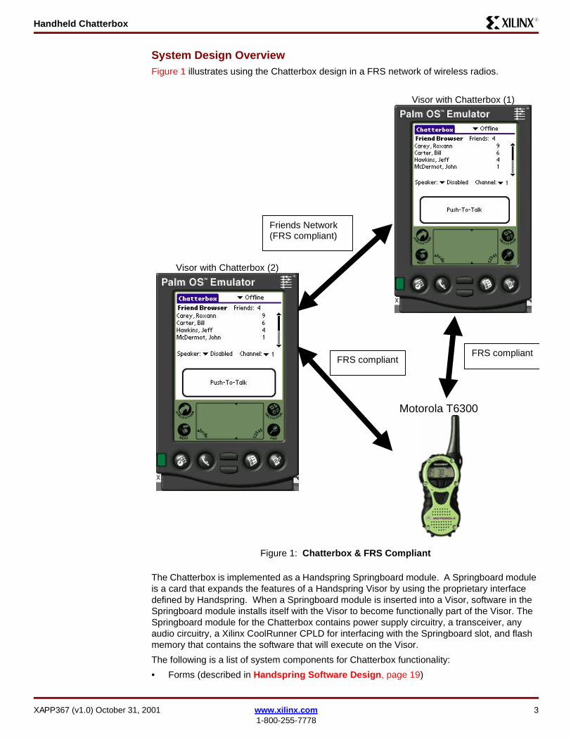
System Design OverviewFigure 1 illustrates using the Chatterbox design in a FRS network of wireless radios.
The Chatterbox is implemented as a Handspring Springboard module. A Springboard module is a card that expands the features of a Handspring Visor by using the proprietary interface defined by Handspring. When a Springboard module is inserted into a Visor, software in the Springboard module installs itself with the Visor to become functionally part of the Visor. The Springboard module for the Chatterbox contains power supply circuitry, a transceiver, any audio circuitry, a Xilinx CoolRunner CPLD for interfacing with the Springboard slot, and flash memory that contains the software that will execute on the Visor.
The following is a list of system components for Chatterbox functionality:
• Forms (described in Handspring Software Design, page 19)
Figure 1: Chatterbox & FRS Compliant
Visor with Chatterbox (2)
Motorola T6300
Visor with Chatterbox (1)
Friends Network(FRS compliant)
FRS compliantFRS compliant
XAPP367 (v1.0) October 31, 2001 www.xilinx.com 31-800-255-7778

Handheld ChatterboxR
• Drivers (described in Handspring Software Design, page 19)
• Application (described in Handspring Software Design, page 19)
• HDL Modules (described in CPLD Design, page 8)
• Circuit (described in Hardware Description, page 8)
A high level block diagram of the Chatterbox system design is shown in Figure 2. A more detailed description of the CPLD and software design is presented later in this application note.
Figure 3 shows the "Cool Module Design Contest" submission for the Chatterbox.
Figure 2: Chatterbox System Design
Handspring Visor PDA
Audio Circuit(LM4834 Audio Power Amp)
CoolRunner XPLA3 CPLD
4 MB Toshiba Flash
Memory
RF Transceiver
CircuitDTMF Circuit(MT8889C)
Figure 3: Chatterbox Design
4 www.xilinx.com XAPP367 (v1.0) October 31, 20011-800-255-7778
Handheld ChatterboxR
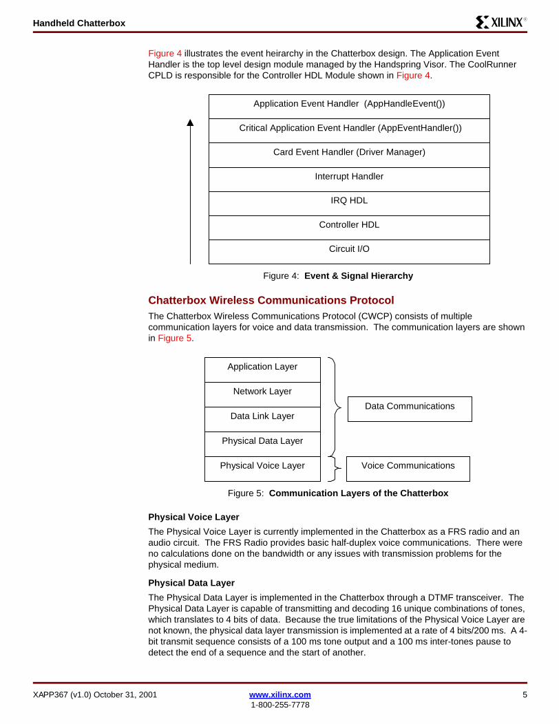
Figure 4 illustrates the event heirarchy in the Chatterbox design. The Application Event Handler is the top level design module managed by the Handspring Visor. The CoolRunner CPLD is responsible for the Controller HDL Module shown in Figure 4.
Chatterbox Wireless Communications ProtocolThe Chatterbox Wireless Communications Protocol (CWCP) consists of multiple communication layers for voice and data transmission. The communication layers are shown in Figure 5.
Physical Voice Layer
The Physical Voice Layer is currently implemented in the Chatterbox as a FRS radio and an audio circuit. The FRS Radio provides basic half-duplex voice communications. There were no calculations done on the bandwidth or any issues with transmission problems for the physical medium.
Physical Data Layer
The Physical Data Layer is implemented in the Chatterbox through a DTMF transceiver. The Physical Data Layer is capable of transmitting and decoding 16 unique combinations of tones, which translates to 4 bits of data. Because the true limitations of the Physical Voice Layer are not known, the physical data layer transmission is implemented at a rate of 4 bits/200 ms. A 4-bit transmit sequence consists of a 100 ms tone output and a 100 ms inter-tones pause to detect the end of a sequence and the start of another.
Figure 4: Event & Signal Hierarchy
Figure 5: Communication Layers of the Chatterbox
Circuit I/O
IRQ HDL
Interrupt Handler
Card Event Handler (Driver Manager)
Critical Application Event Handler (AppEventHandler())
Controller HDL
Application Event Handler (AppHandleEvent())
Physical Voice Layer
Network Layer
Data Link Layer
Physical Data Layer
Application Layer
Data Communications
Voice Communications
XAPP367 (v1.0) October 31, 2001 www.xilinx.com 51-800-255-7778
Handheld ChatterboxR
Using DTMF, the Chatterbox can allow both voice and data communications at the same time and the data will still be detected.
Data Link Layer
The Data Link Layer is implemented as an unacknowledged connectionless service. This whole protocol is meant to be very lightweight.
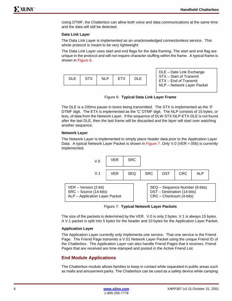
The Data Link Layer uses start and end flags for the data framing. The start and end flag are unique in the protocol and will not require character stuffing within the frame. A typical frame is shown in Figure 6.
The DLE is a 200ms pause in tones being transmitted. The STX is implemented as the '0' DTMF digit. The ETX is implemented as the 'C' DTMF digit. The NLP consists of 15 bytes, or less, of data from the Network Layer. If the sequence of DLW-STX-NLP-ETX-DLE is not found after the last DLE, then the last frame will be discarded and the layer will start over watching another sequence.
Network Layer
The Network Layer is implemented to simply place header data prior to the Application Layer Data. A typical Network Layer Packet is shown in Figure 7. Only V.0 (VER = 00b) is currently implemented.
The size of the packets is determined by the VER. V.0 is only 2 bytes. V.1 is always 15 bytes. A V.1 packet is split into 5 bytes for the header and 10 bytes for the Application Layer Packet.
Application Layer
The Application Layer currently only implements one service. That one service is the Friend Page. The Friend Page transmits a V.01 Network Layer Packet using the unique Friend ID of the Chatterbox. The Application Layer can also handle Friend Pages that it receives. Friend Pages that are received are time-stamped and posted in the Active Friend List.
End Module Applications
The Chatterbox module allows families to keep in contact while separated in public areas such as malls and amusement parks. The Chatterbox can be used as a safety device while camping
Figure 6: Typical Data Link Layer Frame
Figure 7: Typical Network Layer Packets
DLE STX NLP ETX DLE
DLE – Date Link ExchangeSTX – Start of TransmitETX – End of TransmitNLP – Network Layer Packet
V.0 VER SRC
VER – Version (2-bit)SRC – Source (14-bits)ALP – Application Layer Packet
VER SEQ SRC DST CRC ALPV.1
SEQ – Sequence Number (6-bits)DST – Destination (14-bits)CRC – Checksum (4-bits)
6 www.xilinx.com XAPP367 (v1.0) October 31, 20011-800-255-7778
Handheld ChatterboxR
or hiking in remote areas. The Chatterbox is great for kids to use at school or while hanging out with friends.
Operating Instructions
The Chatterbox design can be downloaded from the Xilinx website. The download pack includes the necessary files needed to run the Chatterbox, see Download Pack, page 28.
Please refer to the on-demand video for detailed instructions and demonstration on operating the Chatterbox. This on demand video is available on the Xilinx website at: http://www.xilinx.com/apps/video.htm.
For beaming operations, please use the .prc in the "no hardware WelcomeApplication" directory from the Download Pack, page 28. This provides the same functionality of the Chatterbox without the hardware. The Friend Page functionality can be tested by using the wave files included in the Download Pack, page 28.
Design Tools Insight Springboard Module Development KitThe Insight Springboard Module Development Kit is used for this entry in the "Cool Module Design Contest". The CoolRunner XPLA3 CPLD, Toshiba flash memory, and Springboard connector are utilized on the Chatterbox board. Some components of the Insight Springboard were not used during implementation of the Chatterbox. The extension board of the Springboard Development Kit is used for all the extra audio circuitry, power supply circuitry and RF transceiver.
Handspring Visor PDAA variety of different models of the Visor should be used to check basic compatibility with each version of the Springboard module software interface. The Chatterbox should at least be developed using a Visor, Visor Prism and Visor Edge.
8Mb Toshiba Flash MemoryThe memory module is used to design and debug initial versions of the Chatterbox software. The setup and welcome applications will be used to ensure software compatibility with the Springboard module interface.
CodeWarrior for Palm OS Version 6CodeWarrior was used to develop and debug the setup and welcome application. After the initial prototyping, The Handspring Springboard SDK tools need to be used.
Xilinx WebPACKThe variety of tools from Xilinx can be used to program the CPLD using a Hardware Descprition Language (HDL). The Xilinx WebPACK tool allows a HDL design to be developed and fit to the density requirements of the CPLD . Once the design has been fit, it can be downloaded to the CPLD using the JTAG programmer. More information on the Xilinx WebPACK tools can be found from the Xilinx website at: http://www.xilinx.com/ise/webpack
Handspring Springboard Module Software ToolsA variety of tools from Handspring allow for easier development of the software for Springboard module. The main set of tools are the prc-tools, which compile and link the source to work correctly with the Visor.
EAGLE from CadSoftEagle is a schematic and board layout design tool for creating the daughter board. More information can be found here: http://www.cadsoft.de/
XAPP367 (v1.0) October 31, 2001 www.xilinx.com 71-800-255-7778
Handheld ChatterboxR
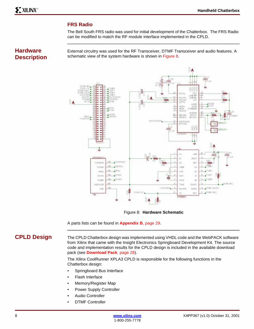
FRS RadioThe Bell South FRS radio was used for initial development of the Chatterbox. The FRS Radio can be modified to match the RF module interface implemented in the CPLD.
Hardware Description
External circuitry was used for the RF Transceiver, DTMF Transceiver and audio features. A schematic view of the system hardware is shown in Figure 8.
A parts lists can be found in Appendix B, page 29.
CPLD Design The CPLD Chatterbox design was implemented using VHDL code and the WebPACK software from Xilinx that came with the Insight Electronics Springboard Development Kit. The source code and implementation results for the CPLD design is included in the available download pack (see Download Pack, page 28).
The Xilinx CoolRunner XPLA3 CPLD is responsible for the following functions in the Chatterbox design:
• Springboard Bus Interface
• Flash Interface
• Memory/Register Map
• Power Supply Controller
• Audio Controller
• DTMF Controller
Figure 8: Hardware Schematic
8 www.xilinx.com XAPP367 (v1.0) October 31, 20011-800-255-7778
Handheld ChatterboxR
• Tone Generator Controller
• RF Transceiver Controller
• Interrupt Request Controller
A description of each CPLD design is described in the following sections.
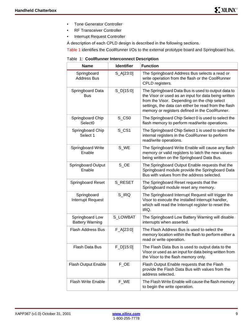
Table 1 identifies the CoolRunner I/Os to the external prototype board and Springboard bus.
Table 1: CoolRunner Interconnect Description
Name Identifier Function
Springboard Address Bus
S_A[23:0] The Springboard Address Bus selects a read or write operation from the flash or the CoolRunner CPLD registers.
Springboard Data Bus
S_D[15:0] The Springboard Data Bus is used to output data to the Visor or used as an input for data being written from the Visor. Depending on the chip select settings, the data can either be read from the flash memory or registers defined in the CoolRunner.
Springboard Chip Select0
S_CS0 The Springboard Chip Select 0 is used to select the flash memory to perform read/write operations.
Springboard Chip Select 1
S_CS1 The Springboard Chip Select 1 is used to select the internal registers in the CoolRunner to perform read/write operations.
Springboard Write Enable
S_WE The Springboard Write Enable will cause any flash memory or valid registers to latch the new values being written on the Springboard Data Bus.
Springboard Output Enable
S_OE The Springboard Output Enable requests that the Springboard module provide the Springboard Data Bus with values from the address selected.
Springboard Reset S_RESET The Springboard Reset requests that the Springboard module reset any memory.
Springboard Interrupt Request
S_IRQ The Springboard Interrupt Request will trigger the Visor to execute the installed interrupt handler, which will read the Interrupt register to reset the IRQ.
Springboard Low Battery Warning
S_LOWBAT The Springboard Low Battery Warning will disable interrupts when asserted.
Flash Address Bus F_A[23:0] The Flash Address Bus is used to select the memory location within the flash to perform either a read or write operation.
Flash Data Bus F_D[15:0] The Flash Data Bus is used to output data to the Visor or used as an input for data being written from the Visor to the flash memory only.
Flash Output Enable F_OE Flash Output Enable requests that the Flash provide the Flash Data Bus with values from the address selected.
Flash Write Enable F_WE The Flash Write Enable will cause the flash memory to begin the write operation.
XAPP367 (v1.0) October 31, 2001 www.xilinx.com 91-800-255-7778
Handheld ChatterboxR
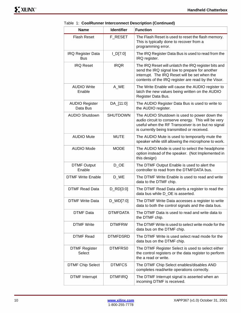
Flash Reset F_RESET The Flash Reset is used to reset the flash memory. This is typically done to recover from a programming error.
IRQ Register Data Bus
I_D[7:0] The IRQ Register Data Bus is used to read from the IRQ register.
IRQ Reset IRQR The IRQ Reset will unlatch the IRQ register bits and send the IRQ signal low to prepare for another interrupt. The IRQ Reset will be set when the contents of the IRQ register are read by the Visor.
AUDIO Write Enable
A_WE The Write Enable will cause the AUDIO register to latch the new values being written on the AUDIO Register Data Bus.
AUDIO Register Data Bus
DA_[11:0] The AUDIO Register Data Bus is used to write to the AUDIO register.
AUDIO Shutdown SHUTDOWN The AUDIO Shutdown is used to power down the audio circuit to conserve energy. This will be very useful when the RF Transceiver is on but no signal is currently being transmitted or received.
AUDIO Mute MUTE The AUDIO Mute is used to temporarily mute the speaker while still allowing the microphone to work.
AUDIO Mode MODE The AUDIO Mode is used to select the headphone option instead of the speaker. (Not Implemented in this design)
DTMF Output Enable
D_OE The DTMF Output Enable is used to alert the controller to read from the DTMFDATA bus.
DTMF Write Enable D_WE The DTMF Write Enable is used to read and write data to the DTMF chip.
DTMF Read Data D_RD[3:0] The DTMF Read Data alerts a register to read the data bus while D_OE is asserted.
DTMF Write Data D_WD[7:0] The DTMF Write Data accesses a register to write data to both the control signals and the data bus.
DTMF Data DTMFDATA The DTMF Data is used to read and write data to the DTMF chip.
DTMF Write DTMFRW The DTMF Write is used to select write mode for the data bus on the DTMF chip.
DTMF Read DTMFDSRD The DTMF Write is used select read mode for the data bus on the DTMF chip.
DTMF Register Select
DTMFRS0 The DTMF Register Select is used to select either the control registers or the data register to perform the a read or write.
DTMF Chip Select DTMFCS The DTMF Chip Select enables/disables AND completes read/write operations correctly.
DTMF Interrupt DTMFIRQ The DTMF Interrupt signal is asserted when an incoming DTMF is received.
Table 1: CoolRunner Interconnect Description (Continued)
Name Identifier Function
10 www.xilinx.com XAPP367 (v1.0) October 31, 20011-800-255-7778
Handheld ChatterboxR
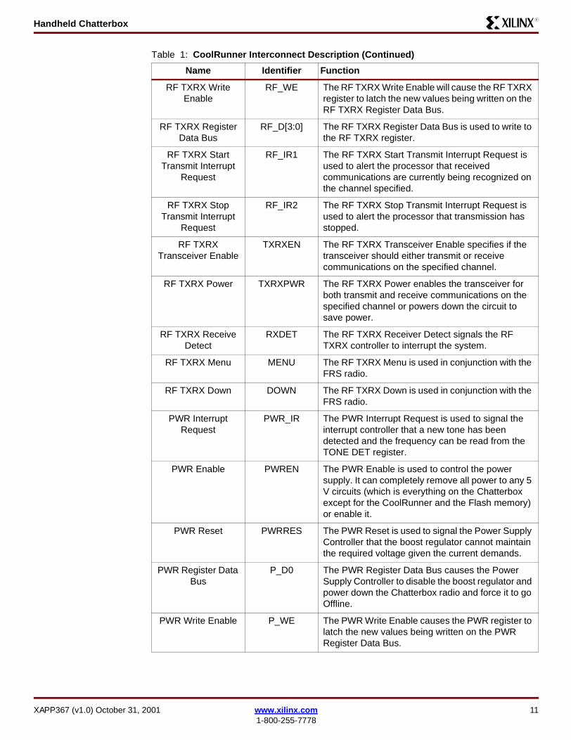
RF TXRX Write Enable
RF_WE The RF TXRX Write Enable will cause the RF TXRX register to latch the new values being written on the RF TXRX Register Data Bus.
RF TXRX Register Data Bus
RF_D[3:0] The RF TXRX Register Data Bus is used to write to the RF TXRX register.
RF TXRX Start Transmit Interrupt
Request
RF_IR1 The RF TXRX Start Transmit Interrupt Request is used to alert the processor that received communications are currently being recognized on the channel specified.
RF TXRX Stop Transmit Interrupt
Request
RF_IR2 The RF TXRX Stop Transmit Interrupt Request is used to alert the processor that transmission has stopped.
RF TXRX Transceiver Enable
TXRXEN The RF TXRX Transceiver Enable specifies if the transceiver should either transmit or receive communications on the specified channel.
RF TXRX Power TXRXPWR The RF TXRX Power enables the transceiver for both transmit and receive communications on the specified channel or powers down the circuit to save power.
RF TXRX Receive Detect
RXDET The RF TXRX Receiver Detect signals the RF TXRX controller to interrupt the system.
RF TXRX Menu MENU The RF TXRX Menu is used in conjunction with the FRS radio.
RF TXRX Down DOWN The RF TXRX Down is used in conjunction with the FRS radio.
PWR Interrupt Request
PWR_IR The PWR Interrupt Request is used to signal the interrupt controller that a new tone has been detected and the frequency can be read from the TONE DET register.
PWR Enable PWREN The PWR Enable is used to control the power supply. It can completely remove all power to any 5 V circuits (which is everything on the Chatterbox except for the CoolRunner and the Flash memory) or enable it.
PWR Reset PWRRES The PWR Reset is used to signal the Power Supply Controller that the boost regulator cannot maintain the required voltage given the current demands.
PWR Register Data Bus
P_D0 The PWR Register Data Bus causes the Power Supply Controller to disable the boost regulator and power down the Chatterbox radio and force it to go Offline.
PWR Write Enable P_WE The PWR Write Enable causes the PWR register to latch the new values being written on the PWR Register Data Bus.
Table 1: CoolRunner Interconnect Description (Continued)
Name Identifier Function
XAPP367 (v1.0) October 31, 2001 www.xilinx.com 111-800-255-7778
Handheld ChatterboxR
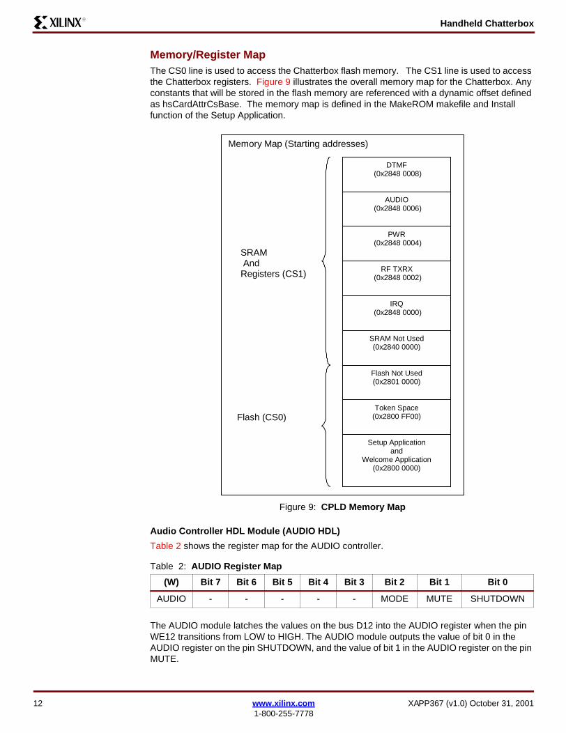
Memory/Register MapThe CS0 line is used to access the Chatterbox flash memory. The CS1 line is used to access the Chatterbox registers. Figure 9 illustrates the overall memory map for the Chatterbox. Any constants that will be stored in the flash memory are referenced with a dynamic offset defined as hsCardAttrCsBase. The memory map is defined in the MakeROM makefile and Install function of the Setup Application.
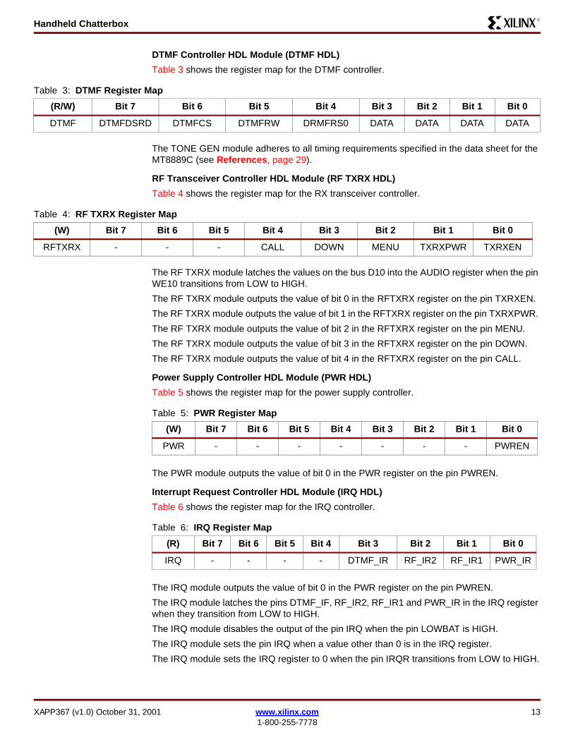
Audio Controller HDL Module (AUDIO HDL)
Table 2 shows the register map for the AUDIO controller.
The AUDIO module latches the values on the bus D12 into the AUDIO register when the pin WE12 transitions from LOW to HIGH. The AUDIO module outputs the value of bit 0 in the AUDIO register on the pin SHUTDOWN, and the value of bit 1 in the AUDIO register on the pin MUTE.
Figure 9: CPLD Memory Map
Table 2: AUDIO Register Map
(W) Bit 7 Bit 6 Bit 5 Bit 4 Bit 3 Bit 2 Bit 1 Bit 0
AUDIO - - - - - MODE MUTE SHUTDOWN
Memory Map (Starting addresses)
IRQ (0x2848 0000)
Flash Not Used(0x2801 0000)
Token Space(0x2800 FF00)
Setup Applicationand
Welcome Application(0x2800 0000)
Flash (CS0)
SRAM AndRegisters (CS1)
DTMF (0x2848 0008)
AUDIO (0x2848 0006)
PWR (0x2848 0004)
RF TXRX (0x2848 0002)
SRAM Not Used(0x2840 0000)
12 www.xilinx.com XAPP367 (v1.0) October 31, 20011-800-255-7778
Handheld ChatterboxR
DTMF Controller HDL Module (DTMF HDL)
Table 3 shows the register map for the DTMF controller.
The TONE GEN module adheres to all timing requirements specified in the data sheet for the MT8889C (see References, page 29).
RF Transceiver Controller HDL Module (RF TXRX HDL)
Table 4 shows the register map for the RX transceiver controller.
The RF TXRX module latches the values on the bus D10 into the AUDIO register when the pin WE10 transitions from LOW to HIGH.
The RF TXRX module outputs the value of bit 0 in the RFTXRX register on the pin TXRXEN.
The RF TXRX module outputs the value of bit 1 in the RFTXRX register on the pin TXRXPWR.
The RF TXRX module outputs the value of bit 2 in the RFTXRX register on the pin MENU.
The RF TXRX module outputs the value of bit 3 in the RFTXRX register on the pin DOWN.
The RF TXRX module outputs the value of bit 4 in the RFTXRX register on the pin CALL.
Power Supply Controller HDL Module (PWR HDL)
Table 5 shows the register map for the power supply controller.
The PWR module outputs the value of bit 0 in the PWR register on the pin PWREN.
Interrupt Request Controller HDL Module (IRQ HDL)
Table 6 shows the register map for the IRQ controller.
The IRQ module outputs the value of bit 0 in the PWR register on the pin PWREN.
The IRQ module latches the pins DTMF_IF, RF_IR2, RF_IR1 and PWR_IR in the IRQ register when they transition from LOW to HIGH.
The IRQ module disables the output of the pin IRQ when the pin LOWBAT is HIGH.
The IRQ module sets the pin IRQ when a value other than 0 is in the IRQ register.
The IRQ module sets the IRQ register to 0 when the pin IRQR transitions from LOW to HIGH.
Table 3: DTMF Register Map
(R/W) Bit 7 Bit 6 Bit 5 Bit 4 Bit 3 Bit 2 Bit 1 Bit 0
DTMF DTMFDSRD DTMFCS DTMFRW DRMFRS0 DATA DATA DATA DATA
Table 4: RF TXRX Register Map
(W) Bit 7 Bit 6 Bit 5 Bit 4 Bit 3 Bit 2 Bit 1 Bit 0
RFTXRX - - - CALL DOWN MENU TXRXPWR TXRXEN
Table 5: PWR Register Map
(W) Bit 7 Bit 6 Bit 5 Bit 4 Bit 3 Bit 2 Bit 1 Bit 0
PWR - - - - - - - PWREN
Table 6: IRQ Register Map
(R) Bit 7 Bit 6 Bit 5 Bit 4 Bit 3 Bit 2 Bit 1 Bit 0
IRQ - - - - DTMF_IR RF_IR2 RF_IR1 PWR_IR
XAPP367 (v1.0) October 31, 2001 www.xilinx.com 131-800-255-7778
Handheld ChatterboxR
VHDL Modules
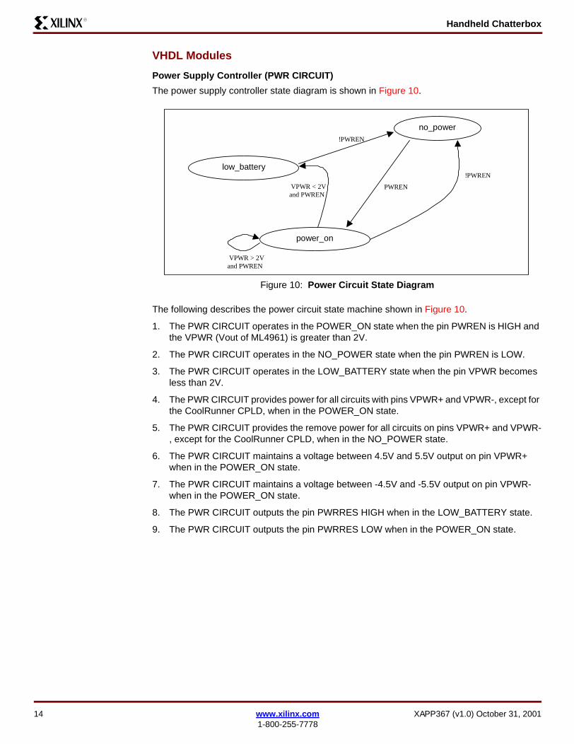
Power Supply Controller (PWR CIRCUIT)
The power supply controller state diagram is shown in Figure 10.
The following describes the power circuit state machine shown in Figure 10.
1. The PWR CIRCUIT operates in the POWER_ON state when the pin PWREN is HIGH and the VPWR (Vout of ML4961) is greater than 2V.
2. The PWR CIRCUIT operates in the NO_POWER state when the pin PWREN is LOW.
3. The PWR CIRCUIT operates in the LOW_BATTERY state when the pin VPWR becomes less than 2V.
4. The PWR CIRCUIT provides power for all circuits with pins VPWR+ and VPWR-, except for the CoolRunner CPLD, when in the POWER_ON state.
5. The PWR CIRCUIT provides the remove power for all circuits on pins VPWR+ and VPWR-, except for the CoolRunner CPLD, when in the NO_POWER state.
6. The PWR CIRCUIT maintains a voltage between 4.5V and 5.5V output on pin VPWR+ when in the POWER_ON state.
7. The PWR CIRCUIT maintains a voltage between -4.5V and -5.5V output on pin VPWR- when in the POWER_ON state.
8. The PWR CIRCUIT outputs the pin PWRRES HIGH when in the LOW_BATTERY state.
9. The PWR CIRCUIT outputs the pin PWRRES LOW when in the POWER_ON state.
Figure 10: Power Circuit State Diagram
PWR CIRCUITState Transition Diagram no_power
low_battery
power_on
PWREN
!PWREN
VPWR < 2Vand PWREN
VPWR > 2Vand PWREN
!PWREN
14 www.xilinx.com XAPP367 (v1.0) October 31, 20011-800-255-7778
Handheld ChatterboxR
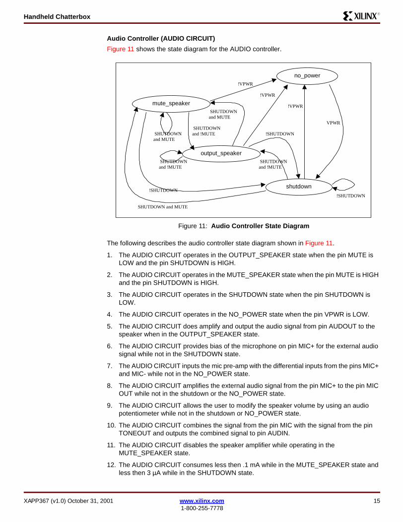
Audio Controller (AUDIO CIRCUIT)
Figure 11 shows the state diagram for the AUDIO controller.
The following describes the audio controller state diagram shown in Figure 11.
1. The AUDIO CIRCUIT operates in the OUTPUT_SPEAKER state when the pin MUTE is LOW and the pin SHUTDOWN is HIGH.
2. The AUDIO CIRCUIT operates in the MUTE_SPEAKER state when the pin MUTE is HIGH and the pin SHUTDOWN is HIGH.
3. The AUDIO CIRCUIT operates in the SHUTDOWN state when the pin SHUTDOWN is LOW.
4. The AUDIO CIRCUIT operates in the NO_POWER state when the pin VPWR is LOW.
5. The AUDIO CIRCUIT does amplify and output the audio signal from pin AUDOUT to the speaker when in the OUTPUT_SPEAKER state.
6. The AUDIO CIRCUIT provides bias of the microphone on pin MIC+ for the external audio signal while not in the SHUTDOWN state.
7. The AUDIO CIRCUIT inputs the mic pre-amp with the differential inputs from the pins MIC+ and MIC- while not in the NO_POWER state.
8. The AUDIO CIRCUIT amplifies the external audio signal from the pin MIC+ to the pin MIC OUT while not in the shutdown or the NO_POWER state.
9. The AUDIO CIRCUIT allows the user to modify the speaker volume by using an audio potentiometer while not in the shutdown or NO_POWER state.
10. The AUDIO CIRCUIT combines the signal from the pin MIC with the signal from the pin TONEOUT and outputs the combined signal to pin AUDIN.
11. The AUDIO CIRCUIT disables the speaker amplifier while operating in the MUTE_SPEAKER state.
12. The AUDIO CIRCUIT consumes less then .1 mA while in the MUTE_SPEAKER state and less then 3 µA while in the SHUTDOWN state.
Figure 11: Audio Controller State Diagram
AUDIO CIRCUITState Transition Diagram no_power
mute_speaker
output_speaker
shutdown
!VPWR
!VPWR
!VPWR
!SHUTDOWN
VPWR
SHUTDOWN and MUTE
!SHUTDOWN
!SHUTDOWN
SHUTDOWNand MUTE
SHUTDOWNand !MUTE
SHUTDOWNand !MUTE
SHUTDOWNand MUTE
SHUTDOWNand !MUTE
XAPP367 (v1.0) October 31, 2001 www.xilinx.com 151-800-255-7778
Handheld ChatterboxR
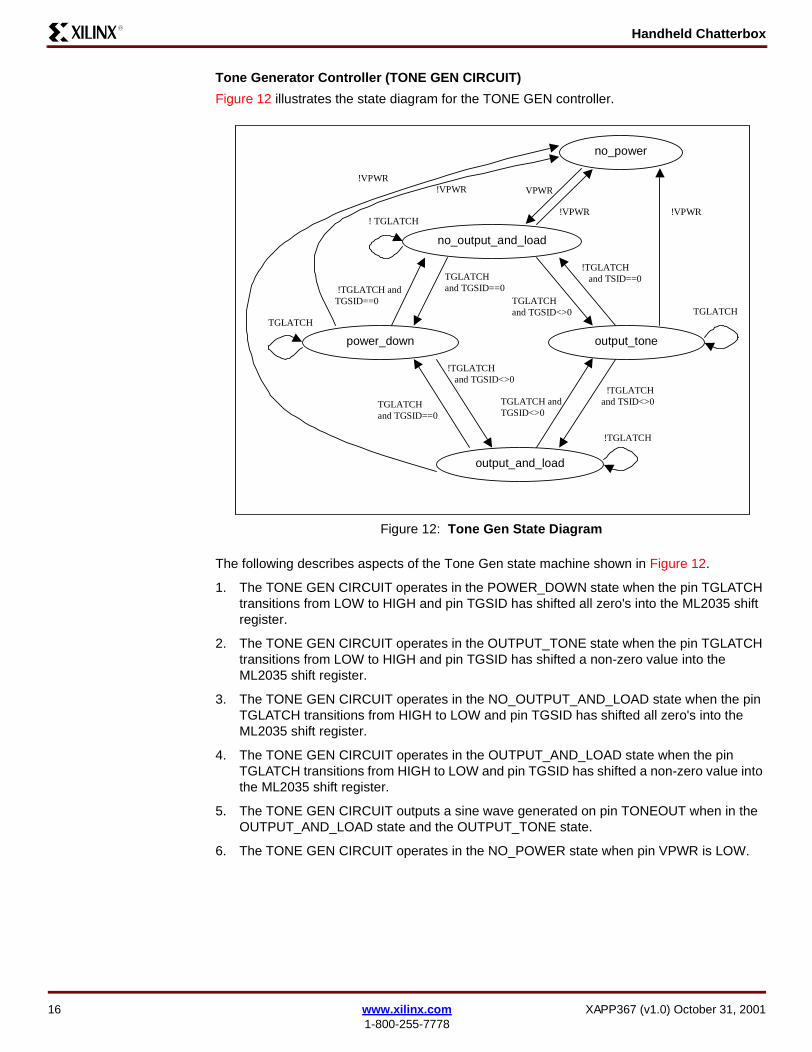
Tone Generator Controller (TONE GEN CIRCUIT)
Figure 12 illustrates the state diagram for the TONE GEN controller.
The following describes aspects of the Tone Gen state machine shown in Figure 12.
1. The TONE GEN CIRCUIT operates in the POWER_DOWN state when the pin TGLATCH transitions from LOW to HIGH and pin TGSID has shifted all zero's into the ML2035 shift register.
2. The TONE GEN CIRCUIT operates in the OUTPUT_TONE state when the pin TGLATCH transitions from LOW to HIGH and pin TGSID has shifted a non-zero value into the ML2035 shift register.
3. The TONE GEN CIRCUIT operates in the NO_OUTPUT_AND_LOAD state when the pin TGLATCH transitions from HIGH to LOW and pin TGSID has shifted all zero's into the ML2035 shift register.
4. The TONE GEN CIRCUIT operates in the OUTPUT_AND_LOAD state when the pin TGLATCH transitions from HIGH to LOW and pin TGSID has shifted a non-zero value into the ML2035 shift register.
5. The TONE GEN CIRCUIT outputs a sine wave generated on pin TONEOUT when in the OUTPUT_AND_LOAD state and the OUTPUT_TONE state.
6. The TONE GEN CIRCUIT operates in the NO_POWER state when pin VPWR is LOW.
Figure 12: Tone Gen State Diagram
TONE GEN CIRCUITState Transition Diagram no_power
power_down output_tone
no_output_and_load
TGLATCHand TGSID<>0 TGLATCH
!VPWR
VPWR
! TGLATCH
!TGLATCH and TGSID<>0
!TGLATCH and TSID==0
!TGLATCHand TSID<>0
!TGLATCH andTGSID==0
TGLATCHand TGSID==0
!TGLATCH
output_and_load
TGLATCHand TGSID==0
TGLATCH
TGLATCH andTGSID<>0
!VPWR
!VPWR !VPWR
16 www.xilinx.com XAPP367 (v1.0) October 31, 20011-800-255-7778
Handheld ChatterboxR
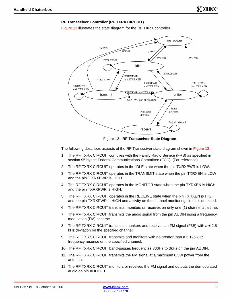
RF Transceiver Controller (RF TXRX CIRCUIT)
Figure 13 illustrates the state diagram for the RF TXRX controller.
The following describes aspects of the RF Transceiver state diagram shown in Figure 13.
1. The RF TXRX CIRCUIT complies with the Family Radio Service (FRS) as specified in section 95 by the Federal Communications Committee (FCC). (For reference)
2. The RF TXRX CIRCUIT operates in the IDLE state when the pin TXRXPWR is LOW.
3. The RF TXRX CIRCUIT operates in the TRANSMIT state when the pin TXRXEN is LOW and the pin T XRXPWR is HIGH.
4. The RF TXRX CIRCUIT operates in the MONITOR state when the pin TXRXEN is HIGH and the pin TXRXPWR is HIGH.
5. The RF TXRX CIRCUIT operates in the RECEIVE state when the pin TXRXEN is HIGH and the pin TXRXPWR is HIGH and activity on the channel monitoring circuit is detected.
6. The RF TXRX CIRCUIT transmits, monitors or receives on only one (1) channel at a time.
7. The RF TXRX CIRCUIT transmits the audio signal from the pin AUDIN using a frequency modulation (FM) scheme.
8. The RF TXRX CIRCUIT transmits, monitors and receives an FM signal (F3E) with a ± 2.5 kHz deviation on the specified channel.
9. The RF TXRX CIRCUIT transmits and monitors with no greater than a 3.125 kHz frequency resonse on the specified channel.
10. The RF TXRX CIRCUIT band-passes frequencies 300Hz to 3kHz on the pin AUDIN.
11. The RF TXRX CIRCUIT transmits the FM signal at a maximum 0.5W power from the antenna.
12. The RF TXRX CIRCUIT monitors or receives the FM signal and outputs the demodulated audio on pin AUDOUT.
Figure 13: RF Transceiver State Diagram
!VPWR
no_power
transmit monitor
idle
TXRXPWRand TXRXEN
TXRXPWRand TXRXEN
VPWR
! TXRXPWR
TXRXPWR and !TXRXEN
!TXRXPWR
Signaldetected
!TXRXPWR
TXRXPWR and TXRXEN
Signal detected
receive
TXRXPWRand !TXRXEN
TXRXPWRand !TXRXEN
No signaldetected
!VPWR
!VPWR !VPWR
XAPP367 (v1.0) October 31, 2001 www.xilinx.com 171-800-255-7778
Handheld ChatterboxR
13. The RF TXRX CIRCUIT asserts the pin RXDET HIGH when any FM signal in the selected channel is detected for more than 10ms while in the RECEIVE state (or when the AUDOUT is at an audible level or signal strength is good enough).
14. The RF TXRX CIRCUIT does not transmit or receive when in the IDLE state.
15. The RF TXRX CIRCUIT does not consume more then .1mA when in the IDLE state.
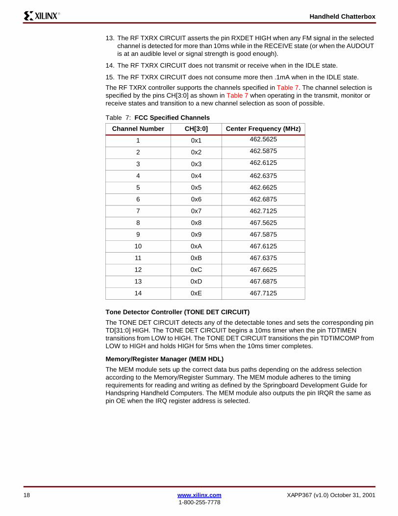
The RF TXRX controller supports the channels specified in Table 7. The channel selection is specified by the pins CH[3:0] as shown in Table 7 when operating in the transmit, monitor or receive states and transition to a new channel selection as soon of possible.
Tone Detector Controller (TONE DET CIRCUIT)
The TONE DET CIRCUIT detects any of the detectable tones and sets the corresponding pin TD[31:0] HIGH. The TONE DET CIRCUIT begins a 10ms timer when the pin TDTIMEN transitions from LOW to HIGH. The TONE DET CIRCUIT transitions the pin TDTIMCOMP from LOW to HIGH and holds HIGH for 5ms when the 10ms timer completes.
Memory/Register Manager (MEM HDL)
The MEM module sets up the correct data bus paths depending on the address selection according to the Memory/Register Summary. The MEM module adheres to the timing requirements for reading and writing as defined by the Springboard Development Guide for Handspring Handheld Computers. The MEM module also outputs the pin IRQR the same as pin OE when the IRQ register address is selected.
Table 7: FCC Specified Channels
Channel Number CH[3:0] Center Frequency (MHz)
1 0x1 462.5625
2 0x2 462.5875
3 0x3 462.6125
4 0x4 462.6375
5 0x5 462.6625
6 0x6 462.6875
7 0x7 462.7125
8 0x8 467.5625
9 0x9 467.5875
10 0xA 467.6125
11 0xB 467.6375
12 0xC 467.6625
13 0xD 467.6875
14 0xE 467.7125
18 www.xilinx.com XAPP367 (v1.0) October 31, 20011-800-255-7778
Handheld ChatterboxR
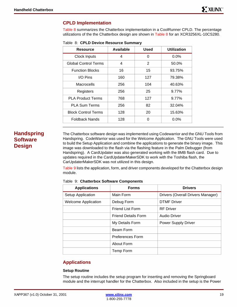
CPLD ImplementationTable 8 summarizes the Chatterbox implementation in a CoolRunner CPLD. The percentage utilizations of the the Chatterbox design are shown in Table 8 for an XCR3256XL-10CS280.
Handspring Software Design
The Chatterbox software design was implemented using Codewarrior and the GNU Tools from Handspring. CodeWarrior was used for the Welcome Application. The GNU Tools were used to build the Setup Application and combine the applications to generate the binary image. This image was downloaded to the flash via the flashing feature in the Palm Debugger (from Handspring). A CardUpdater was also generated working with the 8MB flash card. Due to updates required in the CardUpdaterMakerSDK to work with the Toshiba flash, the CarUpdaterMakerSDK was not utilized in this design.
Table 9 lists the application, form, and driver components developed for the Chatterbox design module.
Applications
Setup Routine
The setup routine includes the setup program for inserting and removing the Springboard module and the interrupt handler for the Chatterbox. Also included in the setup is the Power
Table 8: CPLD Device Resource Summary
Resource Available Used Utilization
Clock Inputs 4 0 0.0%
Global Control Terms 4 2 50.0%
Function Blocks 16 15 93.75%
I/O Pins 160 127 79.38%
Macrocells 256 104 40.63%
Registers 256 25 9.77%
PLA Product Terms 768 127 9.77%
PLA Sum Terms 256 82 32.04%
Block Control Terms 128 20 15.63%
Foldback Nands 128 0 0.0%
Table 9: Chatterbox Software Components
Applications Forms Drivers
Setup Application Main Form Drivers (Overall Drivers Manager)
Welcome Application Debug Form DTMF Driver
Friend List Form RF Driver
Friend Details Form Audio Driver
My Details Form Power Supply Driver
Beam Form
Preferences Form
About Form
Temp Form
XAPP367 (v1.0) October 31, 2001 www.xilinx.com 191-800-255-7778
Handheld ChatterboxR
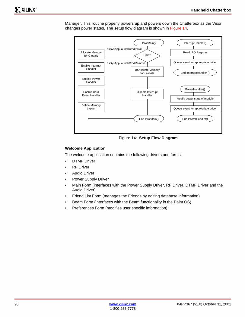
Manager. This routine properly powers up and powers down the Chatterbox as the Visor changes power states. The setup flow diagram is shown in Figure 14.
Welcome Application
The welcome application contains the following drivers and forms:
• DTMF Driver
• RF Driver
• Audio Driver
• Power Supply Driver
• Main Form (interfaces with the Power Supply Driver, RF Driver, DTMF Driver and the Audio Driver)
• Friend List Form (manages the Friends by editing database information)
• Beam Form (interfaces with the Beam functionality in the Palm OS)
• Preferences Form (modifies user specific information)
Figure 14: Setup Flow Diagram
hsSysAppLaunchCmdInstall
PilotMain()
Cmd?Allocate Memory
for Globals
hsSysAppLaunchCmdRemoveEnable Interrupt
Handler
Enable PowerHandler
Enable CardEvent Handler
Define MemoryLayout
End PilotMain()
DeAllocate Memoryfor Globals
InterruptHandler()
End InterruptHandler ()
Read IRQ Register
Queue event for appropriate driver
Disable InterruptHandler
PowerHandler()
End PowerHandler()
Modify power state of module
Queue event for appropriate driver
20 www.xilinx.com XAPP367 (v1.0) October 31, 20011-800-255-7778
Handheld ChatterboxR
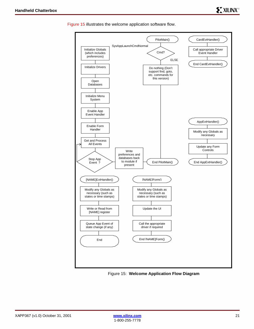
Figure 15 illustrates the welcome application software flow.
Figure 15: Welcome Application Flow Diagram
SysAppLaunchCmdNormal
PilotMain()
Cmd?Initialize Globals(which includes
preferences)ELSE
Initialize Drivers
Writepreferences anddatabases back
to module ifpresent
End PilotMain()
Do nothing (Don’tsupport find, goto,etc. commands for
this version)Open
Databases
Initialize MenuSystem
Enable AppEvent Handler
Enable FormHandler
Get and ProcessAll Events
Stop AppEvent ?
CardEvtHandler()
End CardEvtHandler()
Call appropriate DriverEvent Handler
AppEvtHandler()
End AppEvtHandler()
Modify any Globals asnecessary
Update any FormControls
[NAME]EvtHandler()
End
Modify any Globals asnecessary (such as
states or time stamps)
Queue App Event ofstate change (if any)
Write or Read from[NAME] register
[NAME]Form()
End [NAME]Form()
Modify any Globals asnecessary (such as
states or time stamps)
Call the appropriatedriver if required
Update the UI
[NAME] – the Form and Driver flow diagrams are all similarfor each form and driver used. No sense to duplicate.
XAPP367 (v1.0) October 31, 2001 www.xilinx.com 211-800-255-7778
Handheld ChatterboxR
Forms
User Interface
All forms use the same menu to navigate to different forms in the Chatterbox program. The options are detailed in Table 10, 11, and 12.
Preferences Form
The user can customize various elements in the Chatterbox software. The user can select the mode when online, in an anonymous mode or a friend mode. When the user is in anonymous mode the Chatterbox does not broadcast their presence. When the user is in friend mode the Chatterbox will broadcast their presence in time intervals based on the active friend timeout, another field in the preferences form. Also, the user can select how the Chatterbox should behave when the user exits the program. The user can choose between auto offline or back-ground monitor. When the user selects auto offline the Chatterbox will shutdown the FRS cir-cuit whenever the user exits the chatterbox software. When the user selects background monitor, the FRS will stay on even if the user exits the Chatterbox software. This allows the
Table 10: User Menu
Menu Option Description
Preferences... Directs the user to the preferences form. There the user can customize various elements in the chatterbox software. More information can be found in Preferences Form, page 22.
Friends... Opens up the friend list form. The user can view, edit, and delete friends and friend information from the friend list database. More information can be found in Friends Form, page 23.
Beam Friends... This opens a form that allows the user to send friend information via the IR port to other chatterbox users. More information can be found in Beam Friends Form, page 24.
Beam My Information... This sends the users information via the IR port to other chatterbox users.
Table 11: View Menu
Menu Option Description
Main... Opens up the Main Form. This is the initial form the user sees when starting the chatterbox application. The user can communicate through the FRS to other users, and see what friends are active on the network. More information can be found in Main Form, page 25.
Debug... This opens a form that is specific for development and debugging purposes. Ultimately the end user will not have access to this form. This form allows information to be written to the CoolRunner CPLD, or activate friends or add friends to the friend list.
Table 12: Help Menu
Menu Option Description
About Opens a form about group members involved with the project.
22 www.xilinx.com XAPP367 (v1.0) October 31, 20011-800-255-7778

Handheld ChatterboxR
user to use other applications on the Visor and still be active on the network. Figure 16 illus-trates the Preferences Form user interface.
Friends Form
The Friend List form allows the user to edit and view information about friends in the friend database, or delete friends from the database. Figure 17 illustrates the user interface for the Friend List.
The Friend struct is very similar to the ActiveFriend struct:
Figure 16: Preferences Form GUI
Figure 17: Friends List Form
XAPP367 (v1.0) October 31, 2001 www.xilinx.com 231-800-255-7778

Handheld ChatterboxR
struct Friend{ unsigned int number; char DOB[DOB_LEN], email[EMAIL_LEN], address[ADDRESS_LEN], phone[PHONE_LEN], Fname[FNAME_LEN], Lname[LNAME_LEN];};
The only difference is the channel and time stamp information. The friend method operates on friends structs located in the Friend.h/.c files (see Download Pack, page 28). The methods are virtually identical to the Active Friend methods. And just the Active Friends, they are stored in a Friend database. The methods to operate the Friend database are stored in the FriendDB.h/.c files (see Download Pack, page 28). The methods are virtually identical to the Active Friend database methods.
Once the user is in the Friend List Form there are four actions/buttons the user can take:
1. OK button — Exits out of the Friend List and return to the MainForm
2. Delete Button — Deletes the selected friend from the database
3. Edit Button — Opens the Friend Details form to the edit friend information
4. Details Button — Opens the Friend Details form in a read-only mode so the user can just view the data but not change it.
Beam Friends Form
This form allows the user to send friend information via the IR port to other chatterbox users. When the form is initially loaded the friend list is in a list at the top of the screen. The user can select certain friends to be added to a beam-selection list that will be transferred when the user pushes the "beam 'em" button. The beam list is similar to the friend list, in that it is a data-base. The beam database is a database of Friend structs. The methods for operating on the beam database are similar to the Active Friend database and Friend database. The user can
24 www.xilinx.com XAPP367 (v1.0) October 31, 20011-800-255-7778
Handheld ChatterboxR
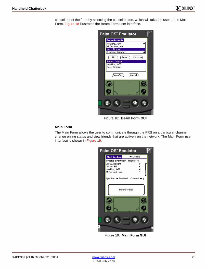
cancel out of the form by selecting the cancel button, which will take the user to the Main Form. Figure 18 illustrates the Beam Form user interface.
Main Form
The Main Form allows the user to communicate through the FRS on a particular channel, change online status and view friends that are actively on the network. The Main Form user interface is shown in Figure 19.
Figure 18: Beam Form GUI
Figure 19: Main Form GUI
XAPP367 (v1.0) October 31, 2001 www.xilinx.com 251-800-255-7778
Handheld ChatterboxR
The active friend information is stored in the ActiveFriend struct, which in turn is stored in a database of active friends (ActiveFriendDB). The ActiveFriend struct is declared below:
struct ActiveFriend{ unsigned int number; unsigned int channel; char DOB[DOB_LEN], email[EMAIL_LEN], address[ADDRESS_LEN], phone[PHONE_LEN], Fname[FNAME_LEN], Lname[LNAME_LEN]; DateTimeType timestamp;
};
The value number is a unique identifier for all friends. The maximum number of unique identifiers is 65535. The value channel is the FRS channel the friend is on. The strings DOB, email, address, phone, Fname and Lname contain information about the friend that the user has entered. The information about the friend is copied over from the Friend List that resides in the user Visor PDA. When a user comes active the friend information from the Friend List gets copied to the Active Friend. The timestamp contains the last time the Active Friend broadcasted his/her presence on the network. When the timestamp expires the Active Friend is removed from the Active Friend database. The Active Friend timeout is specified in the Preferences form. All the functions to operate on Active Friends are in the ActiveFriend.h/.c files (see Download Pack, page 28).
The methods to operate on Active Friends is as follows:
// Sets the date of birthBoolean SetAFDOB(char * inDOB, struct ActiveFriend * f);// Sets email addressBoolean SetAFEmail(char * inEmail, struct ActiveFriend * f);// Set the street adressBoolean SetAFAddress(char * inAddress, struct ActiveFriend * f);// Sets the phone numberBoolean SetAFPhone(char * inPhone, struct ActiveFriend * f);// Sets last nameBoolean SetAFLastName(char * inName, struct ActiveFriend * f);// Sets first nameBoolean SetAFFirstName(char * inName, struct ActiveFriend * f);// Sets first name, last name and channel of the active friendBoolean SetActiveFriend(char * LName,char * FName,unsigned int inNum, struct ActiveFriend * f);// Returns active friend name in the form Last Name, First Namechar * GetAFName(struct ActiveFriend f);// Compared two active friends, returns 0 if they are equal, // < 0 if rec1 < rec2. > 0 if rec1 > rec2.Int ActiveFriendCmp (struct ActiveFriend * rec1, struct ActiveFriend * rec2,Int other);// Copies friend information to active friendvoid CopyToActiveFriends (struct ActiveFriend * dest, struct Friend * src); // Timestamps a friend with the current timevoid StampFriend( struct ActiveFriend *f);
All the functions to operate on Active Friend database are in the ActiveFriendDB.h/.c files (see Download Pack, page 28). The methods to operate on Active Friends is as follows:
// Initializes active friend databasevoid InitActiveDatabase();// Inserts an active friend into the databasevoid InsertActiveFriend (struct ActiveFriend f );// Closes active friend databasevoid CloseActiveDatabase();
26 www.xilinx.com XAPP367 (v1.0) October 31, 20011-800-255-7778
Handheld ChatterboxR
// Returns active friend at current position. Move through databse with// MoveToStartAF, MoveToNextAF, MoveToNthAFstruct ActiveFriend GetActiveFriend();// Move to the first active friend in the databsevoid MoveToStartAF();// Move to the next active friend in the databasevoid MoveToNextAF();// Move to the nth active friend in the databasevoid MoveToNthAF(UInt i);// Returns true if at the end of the database, false otherwiseBoolean EOAFDB();// Returns number of active friends in the database NumActiveRecords();// Sorts active friend database based on ActiveFriendCmpvoid SortActiveFDB();// Delete the nth active friend in the databaseBoolean DeleteActiveRecord (UInt index);// Delete record currently pointed toBoolean DeleteCurrentRecord();// Replace the Active Friend at position I in the databasevoid ReplaceActiveRecord (struct ActiveFriend * f, UInt i);// Find when the next active friend expires, finds the earliest friend // that is going to expire and makes a note of the timevoid FindNextToGo();// Check the current time to see if an active friend expired based on // the time that FindNextToGo decidedvoid CheckTime();
Friend Details Form
This form allows the user to edit friend information. Currently the only information editable is the first name and last name. The unique number is not editable. This value is needed to differentiate users and is a hard coded value for each chatterbox module.
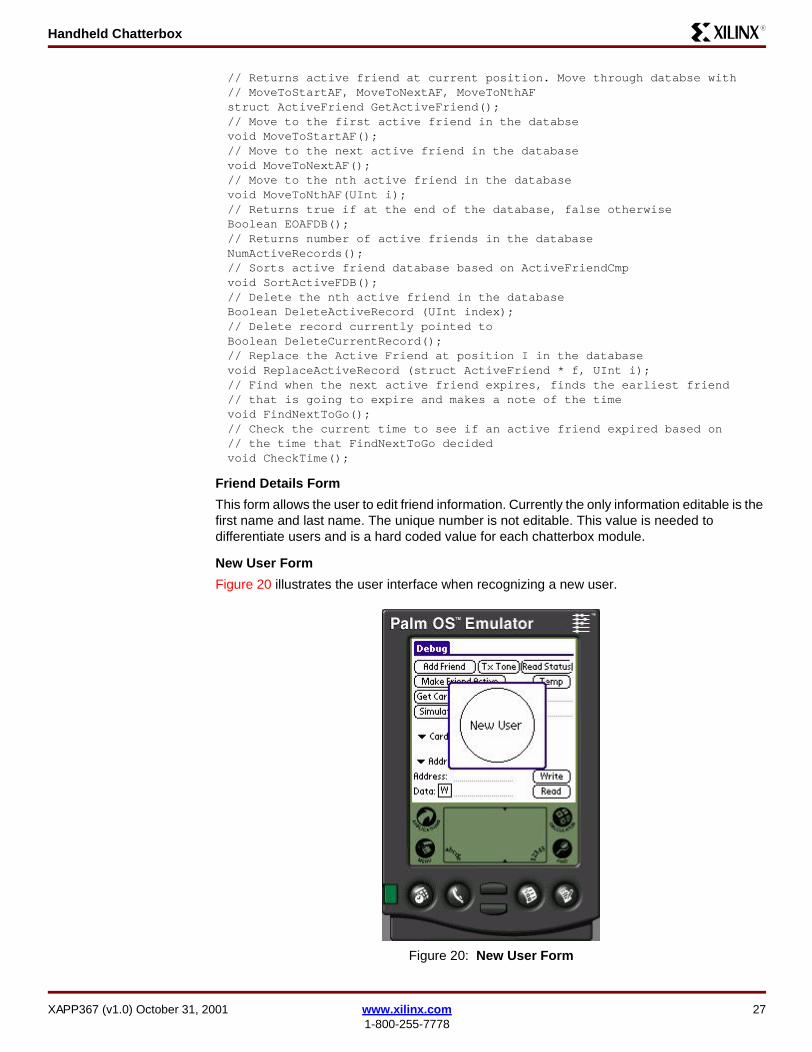
New User Form
Figure 20 illustrates the user interface when recognizing a new user.
Figure 20: New User Form
XAPP367 (v1.0) October 31, 2001 www.xilinx.com 271-800-255-7778
Handheld ChatterboxR
Download Pack THIRD PARTIES MAY HAVE PATENTS ON CHATTERBOX. BY PROVIDING THIS HDL CODE AS ONE POSSIBLE IMPLEMENTATION OF THIS DESIGN, XILINX IS MAKING NO REPRESENTATION THAT THE PROVIDED IMPLEMENTATION OF THIS DESIGN IS FREE FROM ANY CLAIMS OF INFRINGEMENT BY ANY THIRD PARTY. XILINX EXPRESSLY DISCLAIMS ANY WARRANTY OR CONDITIONS, EXPRESS, IMPLIED, STATUTORY OR OTHERWISE, AND XILINX SPECIFICALLY DISCLAIMS ANY IMPLIED WARRANTIES OF MERCHANTABILITY, NON-INFRINGEMENT, OR FITNESS FOR A PARTICULAR PURPOSE, THE ADEQUACY OF THE IMPLEMENTATION, INCLUDING BUT NOT LIMITED TO ANY WARRANTY OR REPRESENTATION THAT THE IMPLEMENTATION IS FREE FROM CLAIMS OF ANY THIRD PARTY. FURTHERMORE, XILINX IS PROVIDING THIS REFERENCE DESIGNS "AS IS" AS A COURTESY TO YOU.
XAPP367 - http://www.xilinx.com/products/xaw/coolvhdlq.htm
Design Limitations
Below is a list of known limitations on the "Cool Module Design Contest" implementation of the Chatterbox design:
• Receiving is not reliable with all DTMF tones.
• Radio Activity Detected message briefly is displayed after many actions when it should not. This is due to implementation using the FRS radio and would require a custom circuit.
• To guarantee that the FRS radio returns to default setting which is known by the Chatterbox software, battery power must be removed from the FRS radio prior to inserting the Insight Springboard into the Visor.
• Power Supply circuit is not implemented. This may cause the FRS radio and Chatterbox software to get out of sync with one another when inserting and removing the module. (The work around is flipping the Card Detect switch Off for five seconds and flipping back On.)
• Proper operations of the Chatterbox require fresh batteries in both the Visor and FRS radio. Low power conditions were not thoroughly tested and some issues have been seen.
Conclusion This design submission for the Cool Module Design Contest is a perfect application of a low power Springboard module. The Chatterbox design uses a low power Xilinx CoolRunner CPLD in conjunction with a DTMF transmitter and receiver. Low power CoolRunner CPLDs are the ideal programmable logic solution for portable, handheld applications. The Chatterbox can be used in everyday applications as a two-way radio.
Appendix A Appendix A lists appropriate Xilinx CoolRunner CPLD application notes. These application notes can be found by searching the Xilinx website (http://www.xilinx.com/)and keying on the specific XAPP#. Many include appropriate driver software along with high level design code. All have been constructed and work.
PDA Springboard DesignXAPP147: Low Power Handspring Springboard Module Design with CoolRunner CPLDs
XAPP359: Understanding the Insight Springboard Development Kit
XAPP357: CoolRunner Visor Springboard LED Test
XAPP355: Serial ADC Interface Using a CoolRunner CPLD
XAPP146: Designing an Eight Channel Digital Volt Meter with the Insight Springboard Kit
XAPP149: Designing an Oscilloscope for the Insight Springboard Development Kit
XAPP349: Pocket Oscilloscope
28 www.xilinx.com XAPP367 (v1.0) October 31, 20011-800-255-7778

Handheld ChatterboxR
ReferencesHandspring website: http://www.handspring.com/
Power Supply Circuit (ML4961) from Fairchild Semiconductor (http://www.fairchildsemi.com/pf/ML/ML4961.html)
DTMF Circuit (MT8889C) from Zarlink Semiconductor (http://products.zarlink.com/partfinder/product_search.cgi?mode=cat&category=15)
Audio Power (LM4834) from National Semiconductor (http://www.national.com/pf/LM/LM4834.html)
Tone Detector Circuit (TLC555) from Texas Instruments (http://focus.ti.com/docs/prod/productfolder.jhtml?genericPartNumber=TLC555)
Appendix B Table 13 describes the parts necessary to build the Chatterbox design described in this document.
Table 13: Parts List
High LevelBlock
Part Number
Part Description
Number of
Units Manufacturer
Handspring Visor PDA
Handheld Computer 1 Handspring
CoolRunner CPLD
XCR3256XL-10CS280
Programmable CPLD (included with Insight Electronics Springboard Development Kit)
1 Xilinx
Flash Memory TC58FVT32F 4 Mb (2M x 16 bit) flash memory(included with Insight Electronics Springboard Development Kit)
1 Toshiba
Power Supply Circuit
ML4961(see Appendix A,
page 28)
Boost Regulator with Detect
1 Fairchild Semiconductor
DTMF Circuit MT8889C (see Appendix A,
page 28)
DTMF Transmitter and Receiver
1 Zarlink Semiconductor
Tone Detector Circuit
TLC555(see Appendix A,
page 28)
Timer 1 Texas Instruments
Audio Circuit Speaker 1
Audio Circuit Audio POT 1
Audio Circuit LM4834(see Appendix A,
page 28)
Audio power Amp with DC volume control and microphone preamp
1 National Semiconductor
RF Circuit Bell South FRS Radio
Transceiver 1
XAPP367 (v1.0) October 31, 2001 www.xilinx.com 291-800-255-7778

Handheld ChatterboxR
Revision History
The following table shows the revision history for this document.
Date Version Revision
10/31/01 1.0 Initial Xilinx release.
30 www.xilinx.com XAPP367 (v1.0) October 31, 20011-800-255-7778