r ·· CENTRAL PACIFIC PLAZA Tele~
7
TRUE GEOTHERMAL ENERGY COMPANY CENTRAL PACIFIC PLAZA February 11 , 1994 Manabu Tagomori Chief Engineer Division of Water & Land Development state Department of Land & Natural Resources 1151 Punchbowl street Honolulu, Hawaii 96813 & r ·· No.: FAX <" .. 220 StretG Suite 8 66"" <f"!\ • ..t'1!' 06813 V" . i ;»: k -o ? '£?,: . . """ Subject: Applicat ion for Permit to Plug and Abandon Well No. KAl-l (True/Mid-Pacific Geothermal venture) at Puna , Island of Hawaii. Dear Mr. Tagomori , Enclosed is an application fo a permit to plug and abandon the above referenced geothermal ell. Also, enclosed as an attachment, is the written d t steps and procedures to be undertaken to complete JueP. abandonment of the well. The pI ug was compl eted in I' nee Ai th the- elepur s administrative rules relating to e and drilling of wells and the conservation District Us Permit issued by the Board of Land & Natural Resource, to True Mid-Pacific . Geothermal Venture which authorized the drilling of 1 -1. Further enclosed is a check for $100.00 to cover the application fee for the permit. The permit application and the plan for accomplishing the plug and abandonment of the well was prepared by ThermaSource, Inc. and Mr. Gerald Niimi and Louis Capuano (drilling and reservoir engineers). We believe that the plan is competent and reasonable and is in conformance with the department's rules relating to the abandonment of geothermal wells. We will greatly appreciate your timely action on this application. Should you have any questions regarding the application or its contents, please call me at 528-3496 or Mr. Gerald Niimi or Mr. Louis Capuano at (707) 523-2960. AGK/mb Very Truly Yours , TRUE Allan G. Kawada u& COMPANY «
Transcript of r ·· CENTRAL PACIFIC PLAZA Tele~

TRUE GEOTHERMAL ENERGY COMPANYCENTRAL PACIFIC PLAZA
February 11 , 1994
Manabu TagomoriChief EngineerDivision of Water & Land Developmentstate Department of Land & Natural Resources1151 Punchbowl streetHonolulu, Hawaii 96813
& r ··Tele~ No.: 8O~8-3496FAX N'o~-526~1j2
<" . . 220 So{j~ng StretG-7'~Suite 866"" <f"!\%~OnOlulu •..t'1!' 06813 ~~.--V" . i;»: k~~ -o~..?,~ ? ~'£?,:. . """~ ~~~
Subject: Applicat ion for Permit to Plug and Abandon WellNo. KAl-l (True/Mid-Pacific Geothermal venture)at Puna , Island of Hawaii.
Dear Mr. Tagomori ,
Enclosed is an application fo a permit to plug and abandonthe above referenced geothermal ell. Also, enclosed as anattachment, is the written pl,~ d t ~i~the steps and proceduresto be undertaken to complete JueP. a~ abandonment of the well.The pI ug was compl eted in I ' nee Ai th the- elepur Li~nt' sadministrative rules relating to e lea~ing and drilling of wellsand the conservation District Us Permit issued by the Board ofLand & Natural Resource, to True Mid-Pacific . Geothermal Venturewhich authorized the drilling of 1 -1.
Further enclosed is a check for $100.00 to cover theapplication fee for the permit. The permit application and theplan for accomplishing the plug and abandonment of the well wasprepared by ThermaSource, Inc. and Mr. Gerald Niimi and LouisCapuano (drilling and reservoir engineers). We believe that theplan is competent and reasonable and is in conformance with thedepartment's rules relating to the abandonment of geothermal wells.We will greatly appreciate your timely action on this application.
Should you have any questions regarding the application or itscontents, please call me at 528-3496 or Mr. Gerald Niimi or Mr.Louis Capuano at (707) 523-2960.
AGK/mb
Very Truly Yours ,
~~~TRUE GEOTHERM~ EN~R~YAllan G. Kawada
~u&
COMPANY
«

True/Mid-Pacific Geothermal Venture
Well KA1-1Abandonment Plan
ThermaSource, Inc.
1-4-94
Pertinent Data
1. Well KA1-l was spudded on November 17, 1989.
2. 30" conductor pipe was set in a 42" hole to a depth of90' below Kelly Bushing.
3. 20 11, 94 ppf, K-55, Buttress casing set in 8 26 11 hole to
a total depth of 704' below Kelly Bushing. 20" casingcemented to surface using Class G Cement.
4. 13-3/8" casing was set in 2 phase, 1st a 1i ner made upof 78 joints (2389') of 72 ppf, L-SO, Buttress casingset in a 11-1/2" hole hung from the 20" by means of a20" X 13-3/S" Midway liner hanger set at 448' in the 20"to a depth of 3370' and cemented across entire interval.2nd phase set as a tie-back made up of 12 joints (452 ')of 68 ppf, L-SO, Buttress casing and cemented from totaldepth to the surface.
5 . A section was cut from the 13-3/8 11 casing from 2128' to217S' . The well was then sidetracked out section ~nd
12-1/4 11 hole dr-illed to 5350.
6. 9-5/S", 47 pp f", L-SO, Buttress casing set as a liner inthe 12-1/4" hole hung from 2485' using a 13-3/8" X 95/8" Midway liner hanger. Ra.n 74 joints (2820.74") of9-5/8" casing and cemented across entire interval.
7 . 8-1/2" open hole dri ll.d to a total depth of 7850'.
B. 7" combination blank and slotted liner (12 joints of 26ppf blank above 56 joints of 26 ppf slotted) hung in the8- 1/2 II .0 pen hole from 5115 ' to tota 1 depth of 7850'.
9. well completed and suspended on 10-14-90.
10. Potential hole in 13-3/8" casing from 1774' to 1782'.
s

True/Mid-PacificKA1-1 Abandonment Plan1-4 -94Page 2
Abandonment Proced~e
Sequences of Operations
1. Prepare location for appropriate rig tocomplete abandonment procedure.
0.5 days 2.
4.0 days 3.
0.5 days 4.
0.5 days 5.
0.5 days 6.
Install blowout preventer stack consisting ofhydraulically controlled dual ram-typepreventers equipped with eso rams and Piperams.
Move in rig to abandon well. Install flowlineon top of blowout preventer stack. Rig uprig and test stack. Start pumping water andmud down well to insure well is dead. Bleedoff any gas pressure that may have accumulatedbelow master valve.
Open well and pick up 8-1/2" bit and run inhole with drill pipe of tubing to top of 7"slotted liner at 5110' to insure cementretainer can be run to setting point.
If successful in running bit to 5110' thentrip out of hole and lay down bit and pick upHalliburton EZSV cement retainer and run inhole with retainer on drill pipe to settingpoint and set same, then proceed to step 6 ofthis procedure. If unsu~cessful in runningbit to 5110' setting depth, attempt todetermine cause for stoppage, determinationshould be made as soon as possible on locationby drilling personnel present and stateRepresentative to remove cause of stoppage oralter abandonment procedure .
.!'. H ,p r EZSV -ceme nt retainer is ' s e ~':' ,~:: ~~J_ 1.Q_: , :. ,I11 i .x,ano pump...en0ugh Hinh Ternp er e t. ur e cem en trld ~ ~ ~de'" to hole cc nd i c i ons to ' f iT l 100 ..1 inear 'f ea t ; n 8 -.' /2 " ; ho 1e'thr'ough re t'"a"f ri'er '''ifnd' -t henfull out of reta i ner .:··.. ·Fn l '·-hol e w1 th mud"s bov e reta1nfl r :' M";x and pump enough::8i.ghT€:mper £l. : '.Jre ·cernent to fi1l 200 lin~rar --feet "of .."S- 5 / 8 " ca s i ng and displace cement to be p l acedirect lyon top ,o L .r: e t a i r.e r . Pull ':; ~Jt o f .;c erne r.t plug and wait on : c emsrrt .f or .. 8... b.9.J.,l~s .
• _ • • • _~ • • _. _ . J •• ~. ~ .. . _ J • • ~ .. . - .. #~ " •• "' • .• • _ .... " • •.. • ~ ... .... . -4

True/Hid -PacificKA1-l Abandonment Procedure1-4-94Page 3
~ ~n and tag top of cement to ve~if~ locationC'!" plug ,.,
0.5 days 7.
0.25 days 8.
Pull up in hole with opened ended drill pipeand set second cement plug from 2385' to2585 I. 200 1i near feet plug stradd ling top of9-5/8" liner located at 2485'. Pullout ofcement plug and pull above top of cement andwait for 8 hours. Tag top of cement andverify location. Pressure up on 13-3/8"casing above cement plug at 2385' to 750 pSl.If casing holds pressure proceed withabandonment, if casing leaks then locate leakwith packer and squeeze off same with cement.Note: If 13- 3/8" does not ho 1e pressur abovecement plug at 2385' an available option wouldbe to set an add it i ona I 13- 3/8" EZsv cementretainer above the leak and plug well withcement above the retainer. See optionalprocedure below.
Pull up in hole to lOa' and set surface cementplug in 13-3/8" casing from lOa' to 6' belowwellhead.
0.5 days 9 . Wait on cement while laying down drill pipe.Feel for cement and if cement is in place thennipple down blowout preventers.
0.5 days 10. Cut off and remove master valves and wellheadassembly. cut and remove casing below groundlevel and weld plate on top of casing.
1 .0 days 11. Rig down and remov~ rig from location.
12. Fill in cellar and mark location of wellhead.Restore location.
8.75 days Total time on Location including Rig up anddown
· ,.,..
~ T~ue/Mid-Paeific
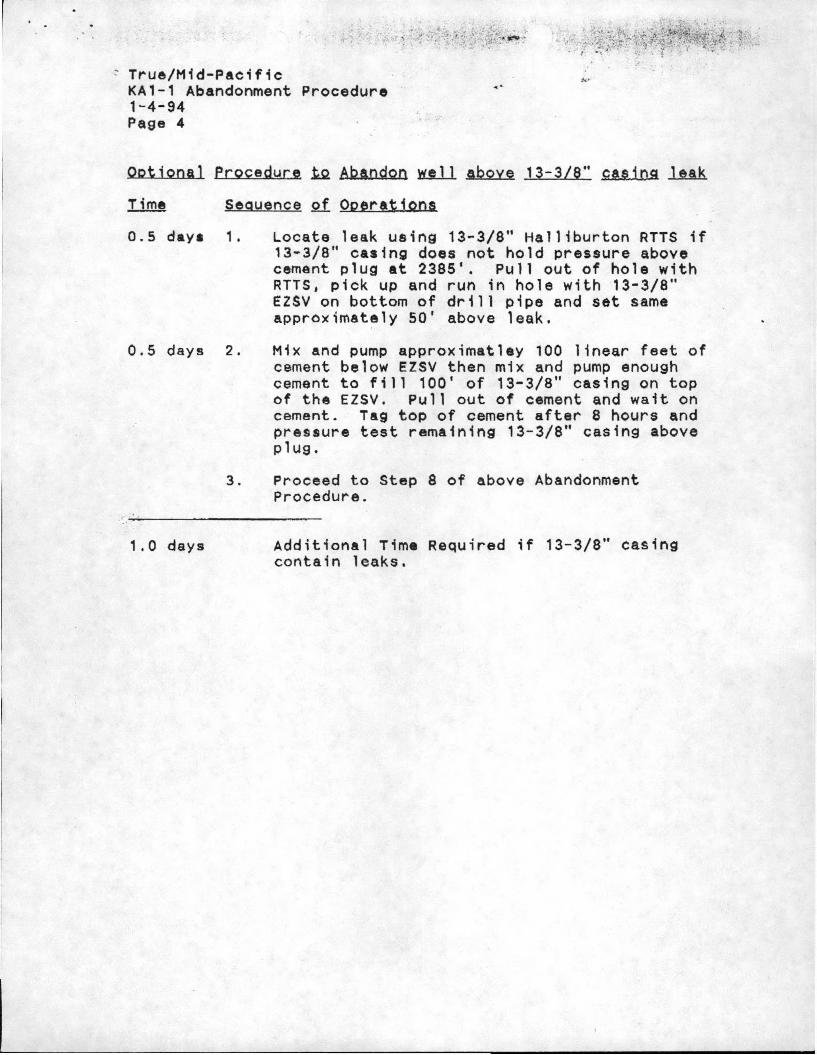
KA1-1 Abandonment Procedure1-4-94Page 4
.- .....
Ootional Procedure .t& AbandQQ~ above 13-3/6" eas1ng leak
Sequence of OperatiQns
0.5 days 1 .
0.5 days 2.
3 .
1.0 days
Locate leak using 13-3/8" Halliburton RTTS if13-3/8" easing does not hold pressure abovecement plug at 2385'. Pullout of hole withRTTS, pick up and run in hole with 13-3/8"EZSV on bottom of drill pipe and set sameapproximately 50' above leak.
Mix and pump approx;matley 100 linear feet ofcement below EZSV then mix and pump enoughcement to fill 100' of 13-3/8" casing on topof the EZSV. Pullout of cement and wait oncement. Tag top of cement after a hours andpre!;su~e test remaining 13-3/8" casing aboveplug.
Proceed to Step 8 of above AbandonmentProcedu~e.
Additional Time Required if 13-3/8" casingcontain leaks.
--- - - - - - - - - - - - - - - - - - - - - - - - - - - - - - - - - - - - - - -

I~----
, -
1000' .
'.
3000'-
4000'·
l 20' CQSlng s,,-I; Q-I; 704'In 0. 26' holi' ,
13-3/8 '" co-sing 0.1;2729',
True /t~ ld-P(lCifIC
GeotherMul Venture'vi ell KA1-1 I
EXist ing \vel l. Prof lle lThe~J"\MQSOUrce) Inc . i
l-5-94 i
5000'
7000'
8000·
9000'
10000/-
9-5/8' liner cE' f'len"te'd In 0. 12-1/4-" hole Fr-on 2485! t o5i ) IjC J
oJ.;)"; ,
7' s lottE'd lIn6'r unc6'PlEmtE"d In Q 9-3/4' hole froM 511S!-l:o 7950/,
8-1/2' open holt' drilled to 7850',

[I
1000'·
2000'
3000'·
4000'·
5000!
6000,jI
7000'
8000·
9000'-
J xxxxx l
~~~ (x.x ~
I
S~rfuce AbnndonM~nt
CeMent plLAQ 0 to 100', . True/~1Id-PucifiC2"0' Co.~lng S;g"t o.t 704'In c 26' hots. Geo-therrr'lol \/eniur'e
C~Ment Plug set froM \,ie tt KA1-12385' to 2585', , AbQndonMent Plcn~~23~~' c:~.sln9 0:1; Ther MQSOUr' ce. Inc I
1-5-94
9-5/8' liner cenentec In 0. 12-1/4' hole' Frcn c485' to5335'.
Ho.lllblArton EZSV Cer-:ent Re'to.lner set In 9-5/8' Co-sing c5110', Cei'1ent se-t o.bove EZSV f'ro""l 5110' lAR -to 4910',
7' slo-tt~cl liner· l.~nr:~Ml:'ntt?d In 0. 8-3/4' hole froM 5115'-to 7850',
8-112; open hole drilled to 7850'.