QWICK KURB, INC.
45
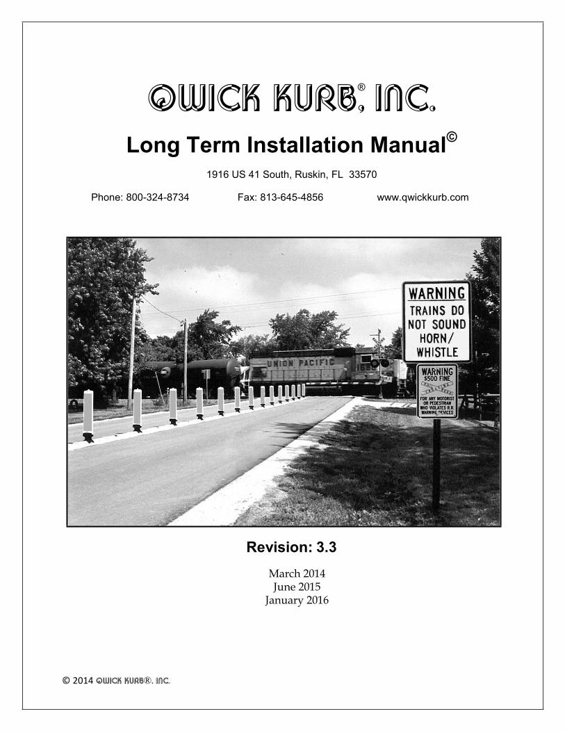
QWICK KURB, INC. Long Term Installation Manual © 1916 US 41 South, Ruskin, FL 33570 Phone: 800-324-8734 Fax: 813-645-4856 www.qwickkurb.com Revision: 3.3 March 2014 June 2015 January 2016 © 2014 QWICK KURB®, INC. ®
Transcript of QWICK KURB, INC.
QWICK KURB, INC.
Long Term Installation Manual©
1916 US 41 South, Ruskin, FL 33570
Phone: 800-324-8734 Fax: 813-645-4856 www.qwickkurb.com
Revision: 3.3
March 2014 June 2015
January 2016 © 2014 QWICK KURB®, INC.
®

QWICK KURB®, INC. Long Term Installation Manual
Interstate Application
Median Application
Edge Line Applications
Private/Proprietary: Not for use or disclosure outside of QWICK KURB®, INC. except by written agreement.
Phone: 800-324-8734 Fax: 813-645-4856 www.qwickkurb.com
1/21/2016 2

QWICK KURB®, INC. Long Term Installation Manual
Table of Contents
INSTRUCTIONS FOR LONG TERM INSTALLATION - 2016 ...............................................6
INTRODUCTION..........................................................................................................................................6 INSTALLATION CONDITIONS...................................................................................................7
TRAFFIC CONSIDERATIONS....................................................................................................................7
SKID RESISTANT GRIPS .............................................................................................................................................................7
WEATHER CONDITIONS ..........................................................................................................................7
TOOLS AND EQUIPMENT CHECKLIST ...................................................................................8 PARTS CHECKLIST .........................................................................................................................9
ILLUSTRATED PARTS ..................................................................................................................10
PREPARING THE ROADWAY FOR INSTALLATION ..........................................................12
CLEANING THE ROADWAY SURFACE...............................................................................................12
LINING THE INTENDED PATHWAY ...................................................................................................12
WATER CHANNELS AND SPACING MARKERS/BOLLARDS .........................................13
USING WATER CHANNELS ...................................................................................................................13
SPACING THE REBOUNDABLE MARKERS/BOLLARDS ................................................................13
SETTING THE L60 SEPARATOR UNITS INTO POSITION ................................................14
SETTING THE L60 SEPARATOR UNITS................................................................................................14
DO NOT DRAG THE L60 SEPARATOR UNITS..................................................................................14
CONNECTING THE L60 SEPARATOR UNITS ...................................................................................17
INSTALLING THE L65 REFLECTIVE ARCS..........................................................................................18
INSTALLING TO THE ROADWAY ...........................................................................................19
FINE TUNING .............................................................................................................................................19
BOLTING TO THE ROADWAY – ASPHALT AND CONCRETE ………….....................................19
INSTALLING THE MARKERS/BOLLARDS .........................................................................................21
ALTERNATE PROCESS: THE Q640 PANEL PULLER TOOL .......................................................... 23
SECURING THE MARKER/BOLLARD WITH THE S65 BLACK SECURING ARCS.......................23
Phone: 800-324-8734 Fax: 813-645-4856 www.qwickkurb.com
1/21/2016 3

QWICK KURB®, INC. Long Term Installation Manual REMOVAL ........................................................................................................................................25
TRAFFIC CONSIDERATIONS..................................................................................................................25
REMOVING THE MARKERS/BOLLARDS............................................................................................25
REMOVING THE L65 REFLECTIVE ARCS ............................................................................................25
DISASSEMBLING THE L60 SEPARATOR UNITS ................................................................................25
UNBOLTING FROM THE ROADWAY - ASPHALT ............................................................................26
PICKING UP THE L60 SEPARATOR ......................................................................................................26
DO NOT DRAG THE L60 SEPARATOR UNITS..................................................................................26 MAINTENANCE .............................................................................................................................27
STORAGE .........................................................................................................................................28
TRANSPORT....................................................................................................................................29
CUSTOMER SERVICE ...................................................................................................................30
REPLACEMENT PARTS ............................................................................................................................30
MEASUREMENTS ......................................................................................................................................30 APPENDIX A - Q640 PANEL PULLER ........................................................................................31
QWICK INSTALLATION ..........................................................................................................................31 APPENDIX B - INSTALLING NEW MARKERS/BOLLARDS TO THE REBOUNDABLE FLEX BOOT ......................................................................................................34
TRAFFIC CONSIDERATIONS..................................................................................................................34
REMOVING THE OLD MARKER/BOLLARD FROM THE REBOUNDABLE FLEX BOOT ..........34
PREPARING THE NEW MARKER/BOLLARD FOR INSTALLATION ON THE REBOUNDABLE FLEX BOOT ..................................................................................................................34
APPENDIX C – PARTS SPECIFICATIONS ...............................................................................36
L60 SEPARATOR UNIT .............................................................................................................................36
L61 MALE END UNIT................................................................................................................................37
L62 FEMALE END UNIT ...........................................................................................................................38
L65 REFLECTIVE MARKER......................................................................................................................39
S65 SECURING ARC ..................................................................................................................................40
L84 FLAT MARKER/BOLLARD ..............................................................................................................41
L104 MEGA MARKER®/BOLLARD.......................................................................................................42
Phone: 800-324-8734 Fax: 813-645-4856 www.qwickkurb.com
1/21/2016 4

QWICK KURB®, INC. Long Term Installation Manual
L125 MARKER/BOLLARD .......................................................................................................................43
L125SH MARKER/BOLLARD..................................................................................................................44
FS50 PAVEMENT ANCHOR …………..................................................................................................45
Phone: 800-324-8734 Fax: 813-645-4856 www.qwickkurb.com
1/21/2016 5

QWICK KURB®, INC. Long Term Installation Manual
INSTRUCTIONS FOR LONG TERM INSTALLATION - 2016
INTRODUCTION
QWICK KURB® is a longitudinal channelizer system of interlocking raised L60 SEPARATOR units, L65 Reflecting Arcs depicting the raised profile of the L60 SEPARATOR, and vertical markers and/or bollards. The system is used instead of asphalt or concrete separators of similar dimensions. It outlasts asphalt, is deployed faster than asphalt and concrete, and it requires less maintenance. It provides superior guidance for the motorist day and night. It is ideal as a traffic separator, and as an edge line guide to channel traffic away from attenuators, to discourage motorists from driving into restricted areas, and to channel in other desirable ways. Installation is quickly mastered by following the techniques in this instruction manual. Dimensions mentioned in the instructions are approximate. Refer to Appendix C – Parts Specifications on page 36 when more precise measurements are needed.
To install on DRAW BRIDGES, contact QWICK KURB®, INC. to obtain additional instructions.
To install in locations where ROAD DEPTH is restricted, contact QWICK KURB®, INC. to obtain alternate anchoring instructions.
CAUTION: The L60 SEPARATOR is not intended for use as a substitute where barrier wall or barrier curb is required. As with temporary asphalt and concrete separator, emergency and other vehicles are able to traverse the L60 SEPARATOR.
The L60 SEPARATOR is designed to help guide the motorist visually, earn driver respect for the visual channelization, assist encroaching drivers to promptly recognize that their vehicles are straying into improper locations, and to minimally deflect the vehicles. The L60 SEPARATOR is not designed to stop vehicles, or to alter their course in a significant manner.
When configuring a vee shape to channelize motorists away from attenuators, place the point of the vee no closer than thirty (30) feet from the attenuator. QWICK KURB® testing has not included closer positioning.
To minimize maintenance of the markers/bollards, designers should take into consideration lane width, along with wide load and truck turning radius requirements.
Phone: 800-324-8734 Fax: 813-645-4856 www.qwickkurb.com
1/21/2016 6

QWICK KURB®, INC. Long Term Installation Manual
INSTALLATION CONDITIONS TRAFFIC CONSIDERATIONS
Whenever possible close both lanes to traffic when installing the System between lanes. If one lane must be kept open during installation, take care to assure that all equipment and personnel are kept clear of the open travel lane. Observe all traffic control regulations. Use flaggers, law enforcement officers, flashing arrow boards, attenuators, and other safety devices as necessary for the conditions present.
RAISED FEET
On the bottom of each L60 SEPARATOR, each L61 Male and L62 Female End unit, are eight raised feet, either molded to the L60 SEPARATOR or added for extra height.
The feet raise the L60 SEPARATOR slightly above the pavement surface so that water can run underneath, though water channels may be necessary if excessive water is likely. Refer to the Using Water Channels section on page 13 for more information.
WEATHER CONDITIONS
The L60 SEPARATOR can be installed permanently under most weather conditions. Heat and cold do not present obstacles. However, before working with electrical equipment in wet conditions, be certain to follow the manufacturer’s instructions to prevent electrical shock or other damage. Refer to the Installing to the Roadway section on page 19 for more information.
Phone: 800-324-8734 Fax: 813-645-4856 www.qwickkurb.com
1/21/2016 7

QWICK KURB®, INC. Long Term Installation Manual
TOOLS AND EQUIPMENT CHECKLIST
For a typical installation, we recommend the items listed below.
NOTE: Always follow manufacturers’ instructions when using any power, impact or other tools and equipment.
Item Description
5 Horsepower Generator 5,000 watts.
Variable Speed Rotary Hammer 300-700 no load rpm and 1,650-3900 rpm; 1” bit capacity, e.g., Bosch Terminator Model 11222EVSG or Milwaukee Hawk Model 5362-1. Drills holes into asphalt or concrete for anchors.
Carbide Tipped Bits for Rotary Hammer
ANSI diameter 3/4”; minimum usable length 10”. The quantity needed depends on the length and number of installations and the density of the underlying material.
Electric Impact Wrench 1/2”; maximum torque 330 ft. lbs., e.g., Ingersoll-Rand Model IR8053 or DeWalt Model DW290 – (connects the L60 SEPARATOR with connecting bolt & nut).
15/16” Shallow Socket Use with electric impact wrench to tighten FS50 anchor sets
17mm Shallow Socket Use with electric impact wrench (for L60 SEPARATOR connecting bolt & nut).
Electric Drill 1/2”; 0 to 550 rpm, variable speed e.g., Makita Model 6402 and a 7/16” Six Point Socket - installs hex screws for S65 black Securing Arcs (use the low setting torque to avoid striping hex heads.)
Extension Cord 50 foot heavy duty grade 12 gauge.
Rubber Hammer Assists in tapping the markers/bollards and L65 Reflective Arcs into place.
Hammer Taps anchors into the drilled holes.
Soapy Water Assists in sliding the markers/bollards into place.
Stiff Broom Clears debris from the intended placement location for the L60 SEPARATOR.
For lengthy installations in excess of 1,000 feet, you may wish to rent our optional Conveyor.
To install a large number of markers/bollards you may wish to purchase our Q640 Panel Puller. Refer to Appendix A on page 31 for more information.
Phone: 800-324-8734 Fax: 813-645-4856 www.qwickkurb.com
1/21/2016 8
QWICK KURB®, INC. Long Term Installation Manual
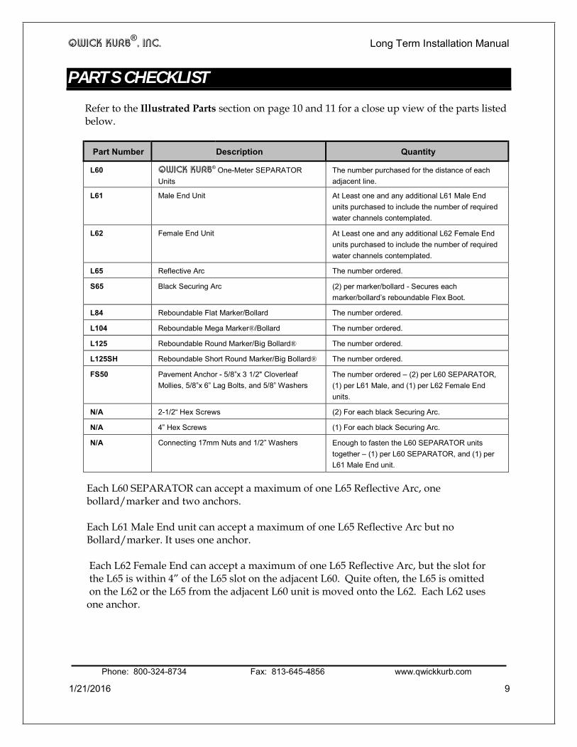
PARTS CHECKLIST
Refer to the Illustrated Parts section on page 10 and 11 for a close up view of the parts listed below.
Part Number Description Quantity
L60 QWICK KURB® One-Meter SEPARATOR Units
The number purchased for the distance of each adjacent line.
L61 Male End Unit At Least one and any additional L61 Male End units purchased to include the number of required water channels contemplated.
L62 Female End Unit At Least one and any additional L62 Female End units purchased to include the number of required water channels contemplated.
L65 Reflective Arc The number ordered.
S65 Black Securing Arc (2) per marker/bollard - Secures each marker/bollard’s reboundable Flex Boot.
L84 Reboundable Flat Marker/Bollard The number ordered.
L104 Reboundable Mega Marker®/Bollard The number ordered.
L125 Reboundable Round Marker/Big Bollard® The number ordered.
L125SH Reboundable Short Round Marker/Big Bollard® The number ordered.
FS50 Pavement Anchor - 5/8”x 3 1/2" Cloverleaf Mollies, 5/8”x 6” Lag Bolts, and 5/8” Washers
The number ordered – (2) per L60 SEPARATOR, (1) per L61 Male, and (1) per L62 Female End units.
N/A 2-1/2“ Hex Screws (2) For each black Securing Arc.
N/A 4” Hex Screws (1) For each black Securing Arc.
N/A Connecting 17mm Nuts and 1/2” Washers Enough to fasten the L60 SEPARATOR units together – (1) per L60 SEPARATOR, and (1) per L61 Male End unit.
Each L60 SEPARATOR can accept a maximum of one L65 Reflective Arc, one bollard/marker and two anchors. Each L61 Male End unit can accept a maximum of one L65 Reflective Arc but no Bollard/marker. It uses one anchor. Each L62 Female End can accept a maximum of one L65 Reflective Arc, but the slot for the L65 is within 4” of the L65 slot on the adjacent L60. Quite often, the L65 is omitted on the L62 or the L65 from the adjacent L60 unit is moved onto the L62. Each L62 uses one anchor.
Phone: 800-324-8734 Fax: 813-645-4856 www.qwickkurb.com
1/21/2016 9

QWICK KURB®, INC. Long Term Installation Manual
ILLUSTRATED PARTS
L62 FEMALE END UNIT
S65 BLACK SECURING ARCS
REBOUNDABLE FLEX BOOT WITH STABILIZING BAR
L65 REFLECTIVE ARC FS50 PAVEMENT
ANCHOR – LAG BOLT, WASHER AND MOLLY
L60 SEPARATOR UNIT
L61 MALE END UNIT
Phone: 800-324-8734 Fax: 813-645-4856 www.qwickkurb.com
1/21/2016 10

Long Term Installation Manual
1/21/2016 11
L125 Big Bollard™- 40” tall from top of bollard
to pavement when mounted.
L104 MEGA-MARKER™- 43” tall from top of
marker to pavement when mounted
L125sh Short Big Bollard™ - 36” tall
from top to pavement when
mounted
L84 Short Panel – 28”
tall from top to pavement
when mounted

QWICK KURB®, INC. Long Term Installation Manual
PREPARING THE ROADWAY FOR INSTALLATION CLEANING THE ROADWAY SURFACE
QWICK KURB® is designed for mounting on generally flat asphalt and concrete surfaces. A long-term installation of the L60 SEPARATOR on gravel, dirt roads, or other loose surfaces may not be effective. Usually, a stiff broom is adequate to prepare an area free from gravel, cinders, sand, and other debris.
The L60 SEPARATOR should not be installed on top of reflective pavement markers (RPMs). Preferably, arrange the alignment of the L60 SEPARATOR to the side of any RPMs in the installation area, or remove the RPMs if appropriate for the conditions. Remove any surface mount delineator that is in the L60 SEPARATOR’s intended position. If the surface is highly irregular, e.g., cobblestones, potholes, etc., or of unstable material which may break or separate if drilled, such as paving bricks, etc., an alternative to the L60 SEPARATOR in that position may be necessary.
LINING THE INTENDED PATHWAY
Use a chalk line or string to make an edge line for the L60 SEPARATOR. Often, the existing painted line is straight enough and in the right location so that no additional lining is necessary.
The L60 SEPARATOR units are 10 5/8” in width. If you are installing over an existing center lane line, for example, it is usually preferable to center the L60 SEPARATOR on the lane line so that the L60 SEPARATOR is evenly distributed between lanes.
Phone: 800-324-8734 Fax: 813-645-4856 www.qwickkurb.com 1/21/2016 12
QWICK KURB®, INC. Long Term Installation Manual
WATER CHANNELS AND SPACING MARKERS/BOLLARDS USING WATER CHANNELS
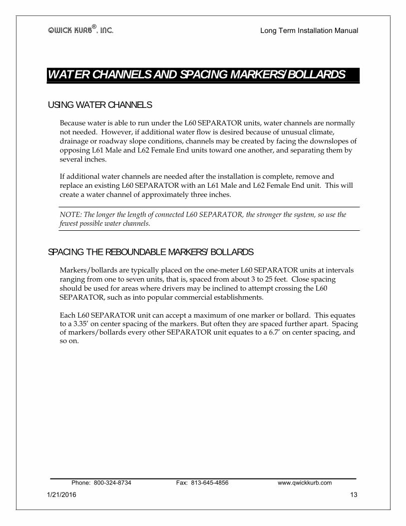
Because water is able to run under the L60 SEPARATOR units, water channels are normally not needed. However, if additional water flow is desired because of unusual climate, drainage or roadway slope conditions, channels may be created by facing the downslopes of opposing L61 Male and L62 Female End units toward one another, and separating them by several inches.
If additional water channels are needed after the installation is complete, remove and replace an existing L60 SEPARATOR with an L61 Male and L62 Female End unit. This will create a water channel of approximately three inches.
NOTE: The longer the length of connected L60 SEPARATOR, the stronger the system, so use the fewest possible water channels.
SPACING THE REBOUNDABLE MARKERS/BOLLARDS
Markers/bollards are typically placed on the one-meter L60 SEPARATOR units at intervals ranging from one to seven units, that is, spaced from about 3 to 25 feet. Close spacing should be used for areas where drivers may be inclined to attempt crossing the L60 SEPARATOR, such as into popular commercial establishments. Each L60 SEPARATOR unit can accept a maximum of one marker or bollard. This equates to a 3.35’ on center spacing of the markers. But often they are spaced further apart. Spacing of markers/bollards every other SEPARATOR unit equates to a 6.7’ on center spacing, and so on.
Phone: 800-324-8734 Fax: 813-645-4856 www.qwickkurb.com 1/21/2016 13

QWICK KURB®, INC. Long Term Installation Manual
SETTING THE L60 SEPARATOR UNITS INTO POSITION SETTING THE L60 SEPARATOR UNITS
Verify that you have the required components to begin the L60 SEPARATOR installation process.
IMPORTANT: Before beginning, inspect all the L60 SEPARATOR components. Never use a damaged or irregular piece of any L60 SEPARATOR component.
DO NOT DRAG THE L60 SEPARATOR UNITS
Sliding the L60 SEPARATOR a few inches to correct alignment is acceptable. However, under no circumstances are the L60 SEPARATOR units ever to be dragged along a hard surface such as a road. If the L60 SEPARATOR units are inadvertently installed in an incorrect location or must otherwise be relocated, you must take up the L60 SEPARATOR units as instructed in the Removal section on page 25, and re-install them in the new location. Alternatively, contact QWICK KURB®, INC. operations personnel for instructions.
Two critical components of the L60 SEPARATOR that can be damaged by dragging are the steel connecting hooks and the raised feet. Dragging a long line of L60 SEPARATOR units may bend the steel connecting hooks, endangering the connections.
Dragging may also wear down the raised feet, which is unacceptable. The raised feet raise the L60 SEPARATOR slightly above the roadway surface to allow water run-off that is not handled by water channels.
Phone: 800-324-8734 Fax: 813-645-4856 www.qwickkurb.com
1/21/2016 14

QWICK KURB®, INC. Long Term Installation Manual
To set the L60 SEPARATOR units:
1. Always begin installation with an L61 Male End unit (the End unit with the steel hook). Place it into position with the slope toward the beginning of the set-up (Fig 1). For panels with single-sided sheeting (uni-drive traffic situations) always install the L60 SEPARATOR in the direction of the traffic flow to insure that the sheeting will face the correct direction when slid into the slot on the L60 SEPARATOR.
NOTE: You can add to an existing installation by removing the L62 Female End unit and continuing with L60 SEPARATORS if further extension is needed.
Fig 1
Install the remaining QWICK KURB® in this direction.
Phone: 800-324-8734 Fax: 813-645-4856 www.qwickkurb.com
1/21/2016 15

QWICK KURB®, INC. Long Term Installation Manual
2. Set the female part of the one-meter L60 SEPARATOR on to the L61 Male End unit’s steel hook so the bolt is exposed on the top of the one-meter L60 SEPARATOR (Fig 2). Snug them together to minimize the gap between curbs.
PUSH CURBS TOGETHER: The system is designed with a small gap between adjoining curbs to facilitate curves in the alignment. Always push the curbs closely together to tighten the gap as much as possible, whether curved or straight. This will discourage dirt and debris from filling the gap.
Fig 2
3. Use the steel hook on the opposite end of the one-meter L60 SEPARATOR to continue the connections.
4. Continue placing one-meter L60 SEPARATOR units in the same manner until
reaching a water channel location or the end of the installation.
Phone: 800-324-8734 Fax: 813-645-4856 www.qwickkurb.com
1/21/2016 16

QWICK KURB®, INC. Long Term Installation Manual
5. At the end of the set-up, place an L62 Female End unit (Fig 3) on to the steel hook and bolt of the last one-meter L60 SEPARATOR.
Fig 3
CAUTION: Never allow the L60 SEPARATOR to be in place without the L61 Male and Female L62 End units properly installed. An uncovered steel hook and the blunt end on the one-meter L60 SEPARATOR would be a danger to vehicles, bicycles, pedestrians, and others.
CONNECTING THE L60 SEPARATOR UNITS
To connect the L60 SEPARATOR units:
6. After the L60 SEPARATOR units have been placed into position on the roadway, Install a ½” washer over the bolt threads and hand tighten a 17mm nut to the connecting bolt.
7. Use the impact wrench with the 17 mm shallow socket to tighten the nut to the bolt
connecting the steel hook of the adjoining L60 SEPARATOR unit.
CAUTION: All bolts must be fastened in order for the system to function safely. Failure to fasten all of the units together creates the risk of separation and shifting. The installer and user assume significant liability if connecting hooks are not secured as instructed.
Phone: 800-324-8734 Fax: 813-645-4856 www.qwickkurb.com
1/21/2016 17

QWICK KURB®, INC. Long Term Installation Manual INSTALLING THE L65 REFLECTIVE ARCS
The L65 Reflective Arcs may be added before or after bolting the L60 SEPARATOR units to the roadway.
To add the L65 Reflective Arcs:
8. Insert the Reflective Arc’s post into the hole (Fig 4) on each one-meter L60
SEPARATOR unit and tap it into place gently with a rubber hammer (if you hammer too hard you may pop out a cats eye).
NOTE: Do not confuse the Arc holes with the Pick-up Tool holes (Fig 5).
Fig 4
9. Insert a Reflective Arc into the hole on the L61 Male End unit.
REFLECTIVE ARC HOLE
PICK-UP TOOL HOLE
Fig 5
Phone: 800-324-8734 Fax: 813-645-4856 www.qwickkurb.com
1/21/2016 18

QWICK KURB®, INC. Long Term Installation Manual
INSTALLING TO THE ROADWAY FINE TUNING
After the L60 SEPARATOR units are in position and before drilling is complete, inspect for correct alignment. Installers may correct minor misalignments by pulling the L60 SEPARATOR sideways.
If a conveyor is used, the easiest way to fine tune is to keep the alignment correct as the units reach the bottom of the conveyor, just prior to exiting.
BOLTING TO THE ROADWAY – ASPHALT AND CONCRETE SURFACES
Installations on both concrete and asphalt surfaces use the FS50 Pavement Anchor which consist of a 5/8”x 3-1/2” nylon expansion molly, a 5/8”x 6” lag screw and 5/8” washers. This assembly will allow the lag screw to be backed out in order to de-install the system. Only a ¾” hole will be left in the pavement which can be filled in with commercially available pavement repair products.
Occasionally, such as on bridge decks and in tunnels, there are depth restrictions for anchor penetration. For 3” maximum depth penetration, use a 5” long lag bolt. Place a mark on the drill bit 5-¼” from the tip, and proceed as indicated above. When measured vertically, the hole will be no more than 3” in depth. For more stringent depth restrictions, contact QWICK KURB®, INC. Customer Service to obtain alternate anchoring instructions, including the use of chemical anchors. To bolt to the roadway:
Each L60 SEPARATOR unit has two holes located on opposing sides that are angled toward the center of the L60 SEPARATOR. Each L61 Male and L62 Female End unit has one hole angled parallel to the length of the L60 SEPARATOR units. Each hole is sized to accommodate the plastic expansion anchor.
1. Drill holes to a minimum depth of 8”.
TIP: Place a mark on the drill bit 8” from the tip. Be especially aware of the possibility of shallow rebar or post tensioning tendons, as damage to drills is a risk.
Phone: 800-324-8734 Fax: 813-645-4856 www.qwickkurb.com
1/21/2016 19

QWICK KURB®, INC. Long Term Installation Manual
2. Using the rotary hammer with the 3/4” bit, insert the bit through the angled hole, and drill into the asphalt road. Do not drill straight down, but rather follow the same angle of the pre-drilled hole in the L60 SEPARATOR, L61 Male End Unit or L62 Female End Unit. When the marked point on the bit is flush with the L60 SEPARATOR, L61 Male End Unit or L62 Female End Unit, a depth adequate to accommodate the bolt and anchor, stop drilling.
TIP: If you have two drills, installers can drill in accord on opposing sides of the L60 SEPARATORS. When drilling the L61 Male End Unit or L62 Female End Unit, have a second person standing on top of the unit to hold it down during drilling.
3. Place a washer on a lag screw, and insert the lag screw into the plastic expansion anchor.
NOTE: This assembly may be built prior to mobilizing on the job site. 4. Use the small hammer to tap the bolt through the hole until it pushes the plastic
expansion anchor through, and bottoms out under the pavement.
5. Use the impact wrench with a 15/16” socket to tighten the bolt until the washer is snug against the L60 SEPARATOR unit, L61 Male End Unit or L62 Female End Unit and the plastic expansion anchor widens beneath the road surface. There is no specific torque requirement for this anchor.
CAUTION: NEVER install a bolt without the washer and nylon molly.
HINT: Temperature extremes can cause the L60 SEPARATOR, L61 Male End Unit and L62 Female End Unit to contract and expand slightly even during the short installation time. Therefore, if you drill all of the holes at one time, you may discover that some of the holes in the L60 SEPARATOR no longer align with the holes you have drilled into the pavement. Ideally, a second installer installs the anchor bolt shortly after the first installer drills the hole.
SPECIAL SHORT LAG SCREW FOR RESTRICTIONS ON DEPTH PENETRATION
Occasionally, such as on bridge decks and in tunnels, there are depth restrictions for anchor penetration. For 3” maximum depth penetration, use a 5” long lag bolt; for a 2” maximum depth, use a 4” long lag. With the 5” lag, place a mark on the drill bit 4-¼” from the tip, and proceed as indicated on Page 19 of the Long Term Manual. With a 4” lag, place a mark on the drill bit 3-¼” from the tip, and proceed as indicated on Page 19 of the Long Term Manual. For more stringent depth restrictions, contact QWICK KURB®, INC. Customer Service to obtain alternate anchoring instructions, including the use of chemical anchors.
Phone: 800-324-8734 Fax: 813-645-4856 www.qwickkurb.com
1/21/2016 20

QWICK KURB®, INC. Long Term Installation Manual
INSTALLING THE MARKERS/BOLLARDS
Consult the project specifications to determine the spacing of the markers/bollards along the length of the separator. Each L60 SEPARATOR unit can accept a maximum of one marker or bollard. This equates to a 3.35’ on center spacing of the markers. But often they are spaced further apart. Spacing of markers/bollards every other SEPARATOR unit equates to a 6.7’ on center spacing, and so on. NOTE: The L84 Flat Marker/Bollard does not have a Stabilizing Bar.
The marker/bollard is best added after the L60 SEPARATOR is bolted into position on the roadway**. The reboundable Flex Boot of the marker/bollard has a narrow edge and a tall edge. The narrow edge of the reboundable Flex Boot of the vertical marker/bollard fits into the center slot of the one-meter L60 SEPARATOR. Notice that there is a small wedge in the slot (Fig 6). It is easier to insert the reboundable Flex Boot in the side where the wedge is located, but inserting from either side is effective.
NARROW SIDE OF THE FLEX BOOT
WEDGE IN THE SLOT
Fig 6
** Some installations pre-install a marker/bollard to an L60 SEPARATOR before arriving on the jobsite. This allows for faster installation and less time in traffic. This method may require greater transport capacity, however, as an L60 SEPARATOR cannot be palletized with an attached marker/bollard.
Phone: 800-324-8734 Fax: 813-645-4856 www.qwickkurb.com
1/21/2016 21

QWICK KURB®, INC. Long Term Installation Manual
To add the markers/bollards:
1. Use soapy water to lubricate the bottom of the marker/bollard and the slide-in slots in the center of the one-meter L60 SEPARATOR. Do not use silicone or petroleum- based lubricants because residue may allow the markers/bollards to ease up from the L60 SEPARATOR and cause them to lean. Position the reboundable Flex Boot into the L60 SEPARATOR slot with the narrow edge facing toward the L60 SEPARATOR. Give it a gentle tap so that the marker/bollard stands on its own (Fig 7).
Fig 7
2. Continue to tap the base with a rubber hammer, while pulling, to help the marker/bollard slide into the slot. The reboundable Flex Boot has two sloping ends to assist sliding it into the L60 SEPARATOR (Fig 8).
Fig 8
Phone: 800-324-8734 Fax: 813-645-4856 www.qwickkurb.com
1/21/2016 22

QWICK KURB®, INC. Long Term Installation Manual
3. The Stabilizing Bars (metal flanges) protruding from the sides of the reboundable Flex Boots are designed to rest tightly on top of the L60 SEPARATOR. Accordingly, do not be concerned if the Stabilizing Bars scrape the top of the L60 SEPARATOR during installation.
HELPFUL NOTE: If the Flex Boot resists sliding into the slot, insert a pry bar between the road and the L60 SEPARATOR unit beneath the slot and raise slightly while tapping the Flex Boot. Raising the L60 SEPARATOR unit at the slot will spread open the slot slightly to allow easer installation of the Flex Boot.
ALTERNATE METHOD: THE Q640 PANEL PULLER TOOL
For easiest installation, we recommend using the Q640 Panel Puller tool. Marker/bollard installation is faster and easier. Refer to Appendix A on page 31 for a description and instructions.
SECURING THE MARKER/BOLLARD WITH THE S65 BLACK SECURING ARCS
There are two S65 black Securing Arcs for the Flex Boot of each marker/bollard. Each S65 black Securing Arc has two short hex head screws and one long hex head screw.
NOTE: This section does not apply to the L84 Flat Marker/Bollard. The L84 Flat Marker/Bollard does not require S65 black Securing Arcs.
IMPORTANT: You must install all 3 screws in each S65 black Securing Arc. Start with the longer 4” screw that installs in the top hole of the S65 black Securing Arc. If you use the short screws first, the Securing Arc may not be tight enough on top.
The S65 black Securing Arcs serve two purposes: discourages theft and strengthens the reboundable Flex Boot connection.
Securing the Stabilizing Bars that protrude from the reboundable Flex Boot reduces the chance of the reboundable Flex Boot popping out of the L60 SEPARATOR’s slot upon a severe vehicular impact on the marker/bollard.
Phone: 800-324-8734 Fax: 813-645-4856 www.qwickkurb.com
1/21/2016 23

QWICK KURB®, INC. Long Term Installation Manual
To secure the markers/bollards:
4. Position the Stabilizing Bars so that their holes are above the pre-molded holes in the top of the L60 SEPARATOR (Fig 9). If necessary, use the rubber hammer to align the Stabilizing Bars with the pre molded holes.
Fig 9
5. Place a black Securing Arc on the L60 SEPARATOR, snugly against one side of the marker/bollard’s reboundable Flex Boot, aligning the hole with the hole in the Stabilizing Bar and the hole in the L60 SEPARATOR.
6. Place the long screw through the single top hole of the S65 black Securing Arc, and
tighten securely.
IMPORTANT: The 4” hex screw must be installed first. For all screws, use 7/16” Six Point Socket to avoid stripping the hex heads. If using an electric drill, DO NOT EXCEED 800 RPM!
7. Place two short screws into the two side holes of the S65 black Securing Arc, and tighten securely.
8. Repeat the process with a second black Securing Arc on the other side of the
reboundable Flex Boot (Fig 10). Continue the process of installing two S65 black Securing Arcs for each marker/bollard’s reboundable Flex Boot.
4” SCREW - FIRST
The Black Securing Arc Requires All 3 Screws! The top Long Screw ALWAYS is installed FIRST!
2-1/2" SCREWS - SECOND
Fig 10
Phone: 800-324-8734 Fax: 813-645-4856 www.qwickkurb.com
1/21/2016 24
QWICK KURB®, INC. Long Term Installation Manual
REMOVAL
Unlike asphalt or concrete curb, QWICK KURB® is reusable. It can be removed to make way for repaving, and then reinstalled inexpensively. Only the plastic expansion mollies must be abandoned. The lag screws and washers can be salvaged and reused.
TRAFFIC CONSIDERATIONS
Whenever possible close both lanes of traffic when removing the L60 SEPARATOR. If one lane must be kept open during removal, take care to assure that all equipment and personnel are kept clear of the open travel lane. Use flaggers, law enforcement officers, flashing arrow boards, attenuators and other safety devices as necessary.
REMOVING THE MARKERS/BOLLARDS
1. Unscrew the S65 black Securing Arcs. Save the hardware and the S65 black Securing
Arcs. Slide the markers/bollards out of the L60 SEPARATOR. Use a rubber hammer to tap the marker/bollard’s reboundable Flex Boot or insert a pry bar into the cavity in the Flex Boot and lift, popping the Flex Boot off of the L60 SEPARATOR.
NOTE: If you have adequate storage space, you may skip this step and leave the markers/bollards in the L60 SEPARATOR.
REMOVING THE L65 REFLECTIVE ARCS
We recommend leaving the L65 Reflective Arcs attached during storage to simplify re-installation.
DISASSEMBLING THE L60 SEPARATOR UNITS
2. Before removing the QWICK KURB® from the roadway, loosen the nuts connecting the
L60 SEPARATOR units, using a 17 mm socket.
Phone: 800-324-8734 Fax: 813-645-4856 www.qwickkurb.com
1/21/2016 25

QWICK KURB®, INC. Long Term Installation Manual UNBOLTING FROM THE ROADWAY
3. Use the impact wrench with the 15/16” socket to back out each of the lag bolts.
Save the undamaged bolts and washers for the next installation. The nylon expansion molly cannot be salvaged.
The remaining hole can be filled with a commercially available pavement repair
product to prevent water intrusion into the pavement. Check with local regulations, specifications and procedures for pavement repair.
PICKING UP THE L60 SEPARATOR
Always start by picking up the L62 Female End unit.
4. Lift up the adjoining one-meter L60 SEPARATOR unit.
5. Continue lifting each remaining L60 SEPARATOR in reverse order, from which it
was installed.
DO NOT DRAG THE L60 SEPARATOR UNITS
Sliding the L60 SEPARATOR a few inches to correct alignment is acceptable. However, under no circumstances are the L60 SEPARATOR units ever to be dragged along a hard surface such as a road. If the L60 SEPARATOR units are inadvertently installed in an incorrect location or must otherwise be relocated, you must take up the L60 SEPARATOR units as instructed in the Removal section on page 25, and re-install them in the new location. Alternatively, contact QWICK KURB®, INC. operations personnel for instructions.
Two critical components of the L60 SEPARATOR that can be damaged by dragging are the steel connecting hooks and the raised feet. Dragging a long line of L60 SEPARATOR units may bend the steel connecting hooks, endangering the connections.
Dragging may also wear down the raised feet, which is unacceptable. The raised feet raise the L60 SEPARATOR slightly above the roadway surface to allow water run-off that is not handled by water channels.
Phone: 800-324-8734 Fax: 813-645-4856 www.qwickkurb.com
1/21/2016 26

QWICK KURB®, INC. Long Term Installation Manual
MAINTENANCE
Inspect the system periodically. Usually the reboundable Flex Boot will not be damaged even if the marker/bollard is. An undamaged reboundable Flex Boot may be used again by removing the damaged part from the Flex Boot, and bolting a new marker/bollard top part to the Flex Boot. Refer to Appendix B on page 34 for instructions on how to replace the tops.
* The L60 SEPARATOR, L61 Male End, and L62 Female End are coated with a special stain resistant material. It will last several years under normal road conditions. Over time, dirt and other debris may accumulate around the curb. Pressure wash or brush away accumulations of such material for optimum visibility.
Contact QWICK KURB®, INC. for a quote to refurbish L60 SEPARATOR units.
If water backs up against the L60 SEPARATOR and better drainage is needed, use L61 Male and L62 Female End units to create additional water channels. At each affected position, simply replace a one-meter L60 SEPARATOR by facing the downslopes of opposing L61 Male and L62 Female End units toward one another, and separating them by several inches.
On rare occasions, the underlying road base is composed of unstable material, which may cause the anchor bolts to loosen. Consider re-tightening if the anchoring system has held successfully for a long time; or consider replacing the anchor with a wider version. You may also re-position the anchors by re-drilling the SEPARATOR in a different position. Please contact QWICK KURB®, INC. for specific instructions.
Phone: 800-324-8734 Fax: 813-645-4856 www.qwickkurb.com
1/21/2016 27

QWICK KURB®, INC. Long Term Installation Manual
STORAGE
To retain QWICK KURB®’s yellow or white color and the optimum reflectivity of the markers/bollards and L65 Reflective Arcs after each use, the units should be pressure washed before storage. The yellow and white L60 SEPARATOR units may be stored outside, off the ground, and covered with a tarp. Stack the one-meter units in a doubled crosshatch pattern. Stack a base row of four (4) one-meter L60 SEPARATOR units on the bottom parallel to one another, and nest three (3) L60 SEPARATOR units upside-down in the cavities between the base row L60 SEPARATOR units. Next, create another base of four (4) parallel L60 SEPARATOR units, perpendicular to the direction of the lower base, and again nest three (3) L60 SEPARATOR units upside-down. Continue in this pattern up to a maximum of sixty-three (63) L60 SEPARATOR units, i.e., nine rows of seven L60 SEPARATOR units (Fig 11).
Do not stack randomly, or leave parts of the sections unsupported. Proper stacking will keep the L60 SEPARATOR from warping or breaking. Do not stack higher than approximately four (4) feet unless there is support on all sides. Do not double stack pallets. Regularly inspect stacked L60 SEPARATOR units to insure that there is no leaning. Shrink- wrap and band when possible.
We recommend that the L 65 Reflective Arcs, S65 black Securing Arcs, and markers/bollards be stored under cover, because long exposure to sunlight and moisture degrades reflective sheeting and these plastics.
NOTE: You may leave the L65 Reflective Arcs attached if palletized.
Care must be taken to insure that units are cross-stacked as directed, and tied down securely and not so high that they fall if jarred; otherwise personal injury and damage may result. Pallets must be strong enough to support the combined weight, and be located on a solid foundation to avoid leaning.
STACK OF 63 L60 SEPARATORS
Fig 11
Phone: 800-324-8734 Fax: 813-645-4856 www.qwickkurb.com
1/21/2016 28

QWICK KURB®, INC. Long Term Installation Manual
TRANSPORT
The recommended manner of transport is on flat bed trucks or heavy-duty trailers. QWICK KURB® is heavy; a one-meter L60 SEPARATOR weighs approximately 34 lbs. Care must be taken to insure that units are secured and not stacked so high that they fall during movement, or personal injury and damage may result. Pallets must be strong enough to support the combined weight. Do not double stack pallets. Transport requires banding or other support suitable for the mode of transportation. Stack units on pallets for transport in the same pattern described in the Storage section on page 28. Pack nuts and washers into a transport safe container.
Markers/bollards should be boxed for transport. Stack the markers/bollards vertical, or lay them horizontally on the thin edge side by side. Either way, you should place them at opposite ends of each other to optimize packing space, and prevent the Stabilizing Bars or reboundable Flex Boots from scraping the sheeting. In addition, it is best to place cardboard or paper between stacks/rows to prevent damage to sheeting. Pack S65 black Securing Arcs, and hardware in transport safe containers. If L65 Reflective arcs are detached, pack them in transport safe containers as well.
Phone: 800-324-8734 Fax: 813-645-4856 www.qwickkurb.com
1/21/2016 29

QWICK KURB®, INC. Long Term Installation Manual
CUSTOMER SERVICE
For advice or help, call QWICK KURB, INC. Customer Service at 800-324-8734 between 8:00 AM and 5:30 PM Eastern Time Zone, Monday-Friday.
REPLACEMENT PARTS
Recommended spare parts include per 1,000 feet of QWICK KURB®: (1) Reflective Arc; (5) marker/bollard tops.
Replacement parts may be ordered from your local distributor. Contact QWICK KURB®, INC. at 1916 US 41 South, Ruskin, Florida 33570 for more information on local distributors.
Phone: 800-324-8734 Fax: 813-645-4856 www.qwickkurb.com
MEASUREMENTS
All measurements in these instructions are approximate as recycled plastic varies in weight, and expands and contracts slightly with temperature variation. The L60 SEPARATOR often referred to above as being “one-meter”, is actually slightly longer at about 3.35 feet or 40 1/8” long. The L61 Male End unit is approximately 1.46 FT or 17 1/2” long. The L62 Female End unit is approximately 1.55 FT or 18 5/8” long.
Phone: 800-324-8734 Fax: 813-645-4856 www.qwickkurb.com
1/21/2016 30

QWICK KURB®, INC. Long Term Installation Manual
APPENDIX A - Q640 PANEL PULLER QWICK INSTALLATION
The reboundable Flex Boot of the marker/bollard has a short edge and a tall edge. The short edge of the reboundable Flex Boot of the vertical marker/bollard fits into the center slot of the one-meter L60 SEPARATOR. Notice that there is a small wedge in the slot (Fig 1). It is easier to draw the reboundable Flex Boot from the opposite side of where this wedge is located, but drawing from either side is effective. Your Panel Puller will grip the horizontal band on the short edge.
SHORT SIDE OF THE FLEX BOOT
WEDGE IN THE SLOT
Fig 1
To use the Q640 Panel Puller:
TIP: Dip the reboundable Flex Boot into soapy water to start. (See page 21)
1. Position the reboundable Flex Boot into the L60 SEPARATOR slot with the short edge facing toward the L60 SEPARATOR. Align the reboundable Flex Boot into the slot, and start it with a gentle kick or hammer tap so that the marker/bollard stands on its own.
2. Tilt the Panel Puller toward the reboundable Flex Boot and use the steel hook to grab
the horizontal edge of the boot (Fig 2). If the metal flanges of the Stabilizing Bar scrape the top of the L60 SEPARATOR, you may have to tap them with a hammer while pulling. Position the holes of the metal flanges to align with the small holes in the top of the L60 SEPARATOR.
Phone: 800-324-8734 Fax: 813-645-4856 www.qwickkurb.com
1/21/2016 31

QWICK KURB®, INC. Long Term Installation Manual
Fig 2
3. Bring the base plate of Panel Puller toward yourself so that it sets flat on the roadway surface, flush against the L60 SEPARATOR (Fig 3).
Fig 3
Phone: 800-324-8734 Fax: 813-645-4856 www.qwickkurb.com
1/21/2016 32
QWICK KURB®, INC. Long Term Installation Manual
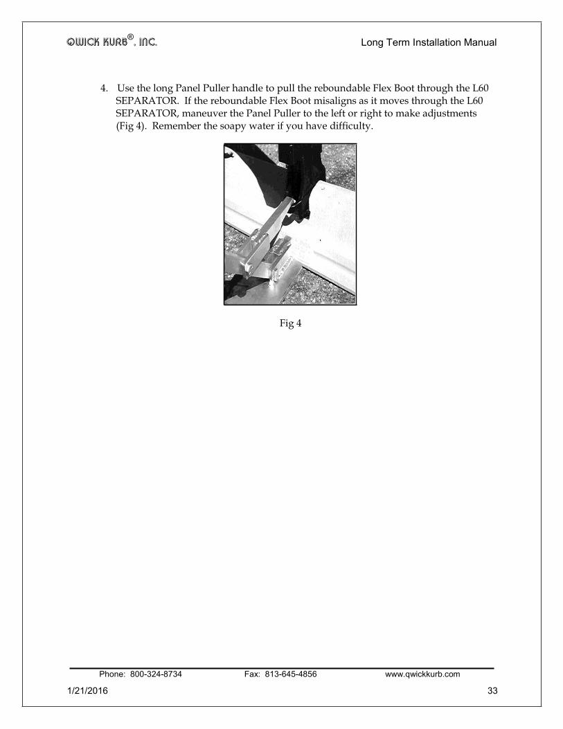
4. Use the long Panel Puller handle to pull the reboundable Flex Boot through the L60 SEPARATOR. If the reboundable Flex Boot misaligns as it moves through the L60 SEPARATOR, maneuver the Panel Puller to the left or right to make adjustments (Fig 4). Remember the soapy water if you have difficulty.
Fig 4
Phone: 800-324-8734 Fax: 813-645-4856 www.qwickkurb.com
1/21/2016 33

QWICK KURB®, INC. Long Term Installation Manual
APPENDIX B - Installing New Markers/bollards to the Reboundable Flex boot
TRAFFIC CONSIDERATIONS
Whenever possible close both adjoining lanes to traffic when replacing markers/bollards on the road. If one lane must be kept open, take care to assure that all equipment and personnel are kept clear of the open travel lane. Observe all traffic control regulations. Use flaggers, law enforcement officers, flashing arrow boards, attenuators and other safety devices as necessary for the conditions present.
REMOVING THE OLD MARKER/BOLLARD TOP FROM THE REBOUNDABLE FLEX BOOT
1. With the old marker/bollard top and reboundable Flex Boot still attached to the L60
SEPARATOR, step on the side of the old marker/bollard to bend it down to the pavement so that you can access the bottom of reboundable Flex Boot.
2. Remove the nuts and washers that attach the old marker/bollard top to the reboundable Flex Boot.
3. Pull up on the old marker/bollard top to detach it from the reboundable Flex Boot
PREPARING THE NEW MARKER/BOLLARD FOR INSTALLATION ON THE REBOUNDABLE FLEX BOOT
1. Remove nuts and washers from the new marker/bollard top.
CAUTION: Be careful that bolts do not slip up into marker/bollard or they will be lost. Keep the bolts pointed down at all times, but do not rest the bolts on a hard surface.
2. Pull firmly on the bolt to assure that proper amount of threads are visible. Twist the bolt head if necessary to properly seat it in its plastic holder.
3. Apply a lubricant such as soapy water to the plastic teeth to help them pass
through the slot in the top-center of the reboundable Flex Boot.
4. Install the bolts of the new marker/bollard top into the holes on the Reboundable Flex Boot, again being careful not to allow the bolts to slide up into the marker/bollard where they would be lost. At this point, the teeth, even with lubrication, will probably not go into the reboundable Flex Boot. Thus, the bolts will not protrude fully through the holes at this stage.
Phone: 800-324-8734 Fax: 813-645-4856 www.qwickkurb.com
1/21/2016 34

QWICK KURB®, INC. Long Term Installation Manual
5. Tilt the new marker/bollard top edgeways so that you can force one bolt through one of the holes sufficiently enough to install the washer and thread the nut several turns.
6. Tilt the new marker/bollard top to the other side, so that you can force the other
bolt through its hole, and install the washer and thread the nut several turns.
7. Tighten both nuts firmly.
8. Firmly press down on the new marker/bollard top to pop the teeth through the slots in the reboundable Flex Boot.
9. Bend the new fully assembled marker/bollard back and forth to test that the
teeth have passed through the reboundable Flex Boot.
Phone: 800-324-8734 Fax: 813-645-4856 www.qwickkurb.com
1/21/2016 35

QWICK KURB®, INC. Long Term Installation Manual
APPENDIX C – PARTS SPECIFICATIONS L60 SEPARATOR UNIT
Phone: 800-324-8734 Fax: 813-645-4856 www.qwickkurb.com
1/21/2016 36

QWICK KURB®, INC. Long Term Installation Manual L61 MALE END UNIT
Phone: 800-324-8734 Fax: 813-645-4856 www.qwickkurb.com
1/21/2016 37
17.5”
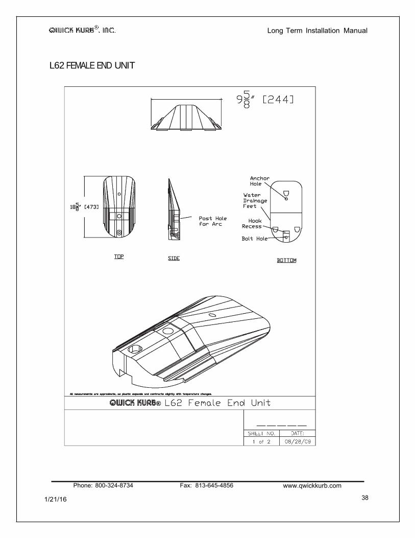
Long Term Installation Manual L62 FEMALE END UNIT
1/21/16
Phone: 800-324-8734 Fax: 813-645-4856 www.qwickkurb.com
38

Long Term Installation Manual
L65 REFLECTIVE ARC
Phone: 800-324-8734 Fax: 813-645-4856 www.qwickkurb.com
1/21/2016 39

QWICK KURB®, INC. Long Term Installation Manual S65 SECURING ARC
1/21/16
Phone: 800-324-8734 Fax: 813-645-4856 wvvw.qwickkurb.com
40

QWICK KURB®, INC Term Installation Manual L84 FLAT MARKER/BOLLARD
1/21/16
Phone: 800-324-8734 Fax: 813-645-4856 www.qwickkurb.com
41

QWICK KURB®, INC. Long Term Installation Manual L104 MEGA MARKER®
Phone: 800-324-8734 Fax: 813-645-4856 www.qwickkurb.com
1/21/16 42

QWICK KURB®, INC. Long Term Installation Manual
L125 BIG BOLLARD®
Phone: 800-324-8734 Fax: 813-645-4856 www.qwickkurb.com
1/21/2016 43

MARKER/BOLLARD
QWICK KURB®, INC. Long Term Installation Manual L125SH SHORT BIG BOLLARD ®
Phone: 800-324-8734 Fax: 813-645-4856 www.qwickkurb.com
1/21/2016 44

QWICK KURB®, INC. Long Term Installation Manual FS50 PAVEMENT ANCHOR
8" X
1/21/2016
Phone: 800-324-8734 Fax: 813-645-4856 wvwv.qwickkurb.com 45