QWEST Technical Publication Enhanced 911 (E-911) …QWEST Tech Pub 77339 Comments Issue B, January...
109
QWEST Technical Publication Enhanced 911 (E-911) Public Service Access Point (PSAP) Environmental Specifications & Equipment Installation Guidelines Copyright 2009 © 77339 Printed in USA Issue B All Rights Reserved January 2010
Transcript of QWEST Technical Publication Enhanced 911 (E-911) …QWEST Tech Pub 77339 Comments Issue B, January...

QWEST Technical Publication
Enhanced 911 (E-911) Public Service Access Point
(PSAP) Environmental Specifications
& Equipment Installation
Guidelines
Copyright 2009 © 77339 Printed in USA Issue B All Rights Reserved January 2010

NOTICE
This document describes the Environmental Requirements and Installation Guidelines, as well as the Powering and Grounding options for Qwest Telecommunications Equipment to be placed on the Customers’ E-911 Public Service Access Point (PSAP) Premises. This document applies only to services that require the placement of Qwest digital multiplexing and/or switching equipment in order to provide FCC or state-tariffed services. The space may be wholly owned by the customer, leased by Qwest, or owned by the building owner or another tenant.
Qwest Communications International Inc. reserves the right to revise this document for any reason, including but not limited to, conformity with standards promulgated by various governmental or regulatory agencies; utilization of advances in the state of the technical arts; or to reflect changes in the design of equipment, techniques, or procedures described or referred to herein.
Liability to anyone arising out of use or reliance upon any information set forth herein is expressly disclaimed, and no representation or warranties, expressed or implied, are made with respect to the accuracy or utility of any information set forth herein.
This document is not to be construed as a suggestion to any manufacturer to modify or change any of its products, nor does this publication represent any commitment by Qwest Communications, Inc. to purchase any specific products. Further, conformance to this publication does not constitute a guarantee of a given supplier's equipment and/or its associated documentation.
Ordering information for Qwest Technical Publications can be obtained from the Reference Section of this document.

QWEST Tech Pub 77339 Comments Issue B, January 2010
COMMENTS on PUB 77339
PLEASE TEAR OUT AND SEND YOUR COMMENTS/SUGGESTIONS TO:
Qwest Jeff Bostow Steven Klocek Kevin Kerkvliet 301 W. 65th St. Room 100 600 Stinson Blvd. 200 S 5th St, 8 Richfield, MN 55423 Minneapolis, MN 55413 Minneapolis, MN 55413 (612) 798-2460 (612) 664-2466 1(866) 366-9063 x5741544
Information from you helps us to improve our Publications. Please take a few moments to answer the following questions and return to the above address.
Was this Publication valuable to you in determining our requirements? YES _______ NO _______
Was the information accurate and up-to-date? YES _______ NO _______
Was the information easily understood? YES _______ NO _______
Were the contents logically sequenced? YES _______ NO _______
Were the printed pages legible? YES _______ NO _______
If you answered NO to any of the questions and/or if you have any other comments or suggestions, please explain: _____________________________________________________________________________ _____________________________________________________________________________ _____________________________________________________________________________
(Attach additional sheet, if necessary) Name __________________________________________ Date ______________________
Company __________________________________________________________________
Address ___________________________________________________________________
___________________________________________________________________
Telephone Number ________________________________________________________

QWEST Tech Pub 77339 Table of Contents Issue B, January 2010
TOC-i
CONTENTS
Chapter and Section Page
1. Introduction....................................................................................................................1-1 1.1 General ................................................................................................................1-1 1.2 Scope....................................................................................................................1-1 1.3 Reason For Reissue............................................................................................1-1
2. General ............................................................................................................................2-1 2.1 Safety and Reliability ........................................................................................2-1 2.2 Types of Customer Premises PSAP Installations..........................................2-1
2.2.1 Cabinet Type ..........................................................................................2-2 2.2.2 Four Post Open Rack Type ..................................................................2-2 2.2.3 Relay Rack Type ....................................................................................2-2
2.3 Priority of Standards.........................................................................................2-2
3. Environmental, Grounding, and Power Check Lists ...............................................3-1 3.1 Customer Premises Environment and Space Information..........................3-1 3.2 Customer Premises Power and Grounding Information ............................3-3
4. Environmental Requirements......................................................................................4-1 4.1 Facility Environmental Conditions, Upkeep, Storage and Handling........4-1 4.2 Equipment Area Guidelines ............................................................................4-2 4.3 Access Guidelines.............................................................................................4-3 4.4 Lighting Guidelines...........................................................................................4-3 4.5 Room Temperature and Humidity Guidelines............................................4-4 4.6 Ventilation and Air Filtration Guidelines.....................................................4-4
4.6.1 Air Quality Guidelines .........................................................................4-4 4.7 Floor Loading and Anchoring Guidelines.....................................................4-5 4.8 Earthquake Zones and Equipment Settings ..................................................4-6 4.9 Fire Systems........................................................................................................4-7
4.9.1 Fire Stopping Guidelines......................................................................4-8 4.10 Asbestos Management Guidelines..................................................................4-84.11 Water/Flood Management Guidelines ..........................................................4-8
5. Powering Guidelines.....................................................................................................5-1 5.1 Essential AC Power from the Customer ........................................................5-1 5.2 Operation without Backup Power ..................................................................5-1

QWEST Tech Pub 77339 Table of Contents Issue B, January 2010
TOC-ii
CONTENTS (Continued)
Chapter and Section Page
6. Grounding Guidelines ..................................................................................................6-16.1 General Grounding Information .....................................................................6-16.2 Telecommunications Ground Collection Point.............................................6-26.3 Single Point Ground System............................................................................6-3
6.3.1 (P) - Surge Producers ............................................................................6-36.3.2 (A) - Surge Absorbers ...........................................................................6-46.3.3 (N) - Non-Isolated Ground Plane (NON-IGP) Equipment Grounds........6-46.3.4 (I) - Isolated Ground Plane (IGP) Equipment Grounds...................6-5 6.3.5 Main Distribution Frame (MDF) Data Rack Bonding & Grounding ....6-6
7. Installation Guidelines..................................................................................................7-1 7.1 General Installation Guidelines and Requirements .....................................7-1
7.1.1 Facility Access and Security.................................................................7-2 7.2 Assembly and Ironwork...................................................................................7-2
7.2.1 Bolts, Nuts, Screws, and Threaded Rods ..........................................7-2 7.2.2 Cable Racks ............................................................................................7-3 7.2.2.1 Main Distribution Frame (Wall-Mounted) Ladder-Type Cable Rack .............................................................................7-3 7.2.3 Frames, Bays, Cabinets, and Stands....................................................7-4 7.2.3.1 Main Distribution Frame (MDF) Control Room.............7-4 7.2.3 Frames, Bays, Cabinets, and Stands....................................................7-4 7.2.4 Framework Parts ...................................................................................7-6 7.2.5 Mounting of Shelves/Equipment .......................................................7-6 7.2.6 Floor Anchors and Installation Instructions......................................7-6
7.3 Cabling: Forming, Running, and Securing ...................................................7-8 7.3.1 Cable Service Loop Requirements ......................................................7-9 7.3.2 Bending and Forming .........................................................................7-11 7.3.3 Cable Protection and Storage.............................................................7-11 7.3.4 Securing and Supporting....................................................................7-12 7.3.5 Cable Pileup .........................................................................................7-13 7.3.6 CAT 5e and Coaxial Cables................................................................7-13 7.3.7 Fiber Optic Cable Protective/Distribution Systems.......................7-13 7.3.8 Repair of Damaged Cables.................................................................7-14 7.3.9 Splicing Cables, and Mated Connectable Cables............................7-14 7.3.10 Use of Nylon and Plastic Cable Ties.................................................7-15

QWEST Tech Pub 77339 Table of Contents Issue B, January 2010
TOC-iii
CONTENTS (Continued)
Chapter and Section Page
7.4 E-911 Operator/Position & Data Rack Wiring............................................7-15 7.4.1 Analog Circuits (2 or 4-Wire).............................................................7-16 7.4.2 Horizontal Cabling..............................................................................7-16 7.4.3 Work Station Outlet Wiring...............................................................7-16 7.4.4 Main Distribution Frame (MDF) Patch Panel Assembly (Method 1) ................................................................................................................7-17 7.4.5 Main Distribution Frame (MDF) Patch Panel Assembly (Method 2) ................................................................................................................7-18 7.4.6 MDF Rack Wire Management ...........................................................7-20 7.4.7 Patch Cord Color Guide and Dress Requirements.........................7-20 7.4.8 Wall Field and Integrations................................................................7-20 7.4.9 Wall Mounted Solution ......................................................................7-21 7.4.10 Data Rack Mounted Solution.............................................................7-22 7.4.10.1 110-Block and Patch Panel Application Integration........7-24 7.4.11 Centralized Automatic Message Accounting (CAMA) Trunk
Integration Interface Trunk Transfer................................................7-26 7.4.12 Administrative Line/Trunk Integration ..........................................7-26 7.4.13 Logging Voice Recorder (LVR) Connections ..................................7-27 7.4.14 Private Branch Exchange (PBX) Wall Field Layout........................7-27 7.4.15 MDF 110-Block Information .............................................................7-27 7.4.16 Point of Demarcation (DEMARC).....................................................7-27
7.5 Connecting........................................................................................................7-28 7.5.1 Crimp Compression Connectors, Splicing, and Taps ....................7-28 7.5.2 Quick Clip/Slotted Beam Connections............................................7-29
7.6 Equipment Designations ................................................................................7-29 7.6.1 Designation Conventions ...................................................................7-30
7.7 Power and Battery Installation Requirements and Guidelines ................7-32 7.7.1 DC Power Connections.......................................................................7-32 7.7.2 AC Circuit Installation........................................................................7-34
7.8 Proper Grounding Methods ..........................................................................7-34 7.8.1 Grounding Connections .....................................................................7-35 7.8.2 Grounding Conductors ......................................................................7-36 7.8.3 Isolated and Integrated Grounding Considerations ......................7-37

QWEST Tech Pub 77339 Table of Contents Issue B, January 2010
TOC-iv
CONTENTS (Continued)
Chapter and Section Page 7.9 Hazardous Material Handling ......................................................................7-37 7.10 Installation Documentation ...........................................................................7-38
7.10.1 Commonly Used Installation/Removal Forms ..............................7-38 7.10.2 Job Packet and Job Log .......................................................................7-39 7.10.3 Job Completion or Exclusion Reporting ..........................................7-40 7.10.4 Service Interruption/Degradation Report.......................................7-40 7.10.5 Returning Material ..............................................................................7-40
7.11 Installation Methods of Procedure (MOP’s)................................................7-41 7.11.1 General MOP........................................................................................7-42 7.11.2 Detailed MOP.......................................................................................7-42 7.11.3 MOP Header Fields.............................................................................7-42 7.11.4 MOP Work Description Details.........................................................7-44 7.11.5 MOP Write-Up Review.......................................................................7-46 7.11.6 MOP Approval/Signing Authorities ...............................................7-46 7.11.7 Service Interruptions...........................................................................7-46
8. References.......................................................................................................................8-1 8.1 Acronyms and Definitions ...............................................................................8-1 8.2 Qwest Technical Publications..........................................................................8-4 8.3 Telcordia Documents ........................................................................................8-4 8.4 Other Documents ..............................................................................................8-5 8.5 Ordering Information .......................................................................................8-6 8.6 Trademarks.........................................................................................................8-9
Tables Page 3-1 Customer Premises Environment & Space Checklist ..............................................3-1 3-2 Customer Premises Power Checklist..........................................................................3-3 3-3 Customer Premises Grounding Checklist .................................................................3-4 4-1 Temperature and Humidity Requirements for Optimal Operation ......................4-4 7-1 Cable Pile-up on Horizontal Cable Rack .................................................................7-13 7-2 Labeling Guidelines Checklist...................................................................................7-31 7-3 Common Installation/Removal forms.....................................................................7-38

QWEST Tech Pub 77339 Table of Contents Issue B, January 2010
TOC-v
CONTENTS (Continued)
Figures Page 4-1 Earthquake Zone Map of the 48 Contiguous States .................................................4-7
7-1 Example of Wall-Mounted Ladder-Type Cable Rack..............................................7-3 7-2 Examples of Data Rack Placement..............................................................................7-4 7-3 Properly-Installed Server, Monitor, and Keyboard Shelf........................................7-5 7-4 Bay Floor Anchor Placement Scheme.........................................................................7-7 7-5 Example of Cable Vertical Transition with Chain Support.....................................7-9 7-6 Example of a Proper Waterfall Installation and Supported Cable Bundles .........7-9 7-7 Example of IDF Service Loop ....................................................................................7-10 7-8 Example of Work Station Service Loop....................................................................7-11 7-9 Typical Work Station Outlet Assembly....................................................................7-17 7-10 Example of an RJ45 Unloaded Patch Panel with Jacks ..........................................7-17 7-11 Examples of RJ45 Fully-Loaded 24/48-Position Patch Panel with Jacks ............7-18 7-12 Example of Properly-Installed MDF Patch Panel Assembly ................................7-19 7-13 Example of Dual-Rack Unit Wire Managers Assembly.........................................7-20 7-14 Wall-Mounted Solution Example..............................................................................7-22 7-15 Data Rack-Mounted Solution ....................................................................................7-23 7-16 Example of a 110-Block with Multiple Point Connections....................................7-24 7-17 Example of a 110-Block-to-Patch Panel ....................................................................7-25 7-18 Example of a CAMA Trunk Interface.......................................................................7-26 7-19 Example of ADMIN Line/Trunk Integration .........................................................7-26 7-20 Example of LVR Connection......................................................................................7-27 7-21 Two-Hole Crimp Connector ......................................................................................7-36 7-22 Installation Check List for Site Acceptance .............................................................7-48 7-23 RG 47-0163 Detailed Method of Procedure (DMOP) for E-911
Installation/Removal/Modifications.......................................................................7-52 7-24 RG 47-0013 Service Degradation Report..................................................................7-60

QWEST Tech Pub 77339 Chapter 1 Issue B, January 2010 Introduction
TOC 1-i
CONTENTS
Chapter and Section Page
1. Introduction ................................................................................................................... 1-1 1.1 General................................................................................................................ 1-1 1.2 Scope ................................................................................................................... 1-1 1.3 Reason For Reissue ........................................................................................... 1-1
QWEST Tech Pub 77339 Chapter 1 Issue B, January 2010 Introduction
1-1
1. Introduction
1.1 General
This document describes the Environmental Requirements and Installation Guidelines, as well as the Powering and Grounding options for Qwest Communications Telecommunications Equipment to be placed on the Customers’ Public Service Access Point (PSAP) Premises. This document applies only to Enhanced 911 (E-911) services that require the installation of Qwest (or selected vendor) analog and digital multiplexing and/or switching equipment. The space may be wholly-owned by the customer, leased by Qwest, or owned by the building owner or another tenant.
1.2 Scope
There are many services sold by Qwest where the economical option for delivering these services is to place Telecommunications Equipment on the Customers Premises. (This publication covers Government-type customer premises equipment, such as multiplexers, digital loop carrier, etc. Typically the end-user customer of the Qwest services owns the space outright, but allows Qwest to place its equipment there in order to serve them. Some of this telecommunications equipment comes in pre-packaged lockable cabinets that can be placed in many locations in a building. In other applications it is mounted in relay racks in an equipment or mechanical room. Sometimes it will share rooms with other telecommunications equipment providers, or with the telecommunications equipment owned outright by customers (e.g., PBX).
In all cases, decisions must be made up front about items such as backup Power, Alarms, Distributing Frames, Equipment floor space, Equipment Environment, etc. All of this requires the coordinated effort of the various Qwest Marketing groups, Designed Services group, Engineering, Installation/Construction and the Customer. Coordinated effort by these groups in adherence to the requirements and guidelines of this document will ensure that the customer receives safe and reliable telecommunications services from Qwest.
1.3 Reason For Reissue
This publication will be re-issued occasionally to update installation requirements, and make numerous other small changes. When that occurs, those changes and the reason for the reissue will be stated here.

QWEST Tech Pub 77339 Chapter 2 Issue B, January 2010 General
TOC 2-i
CONTENTS
Chapter and Section Page
2. General............................................................................................................................ 2-1 2.1 Safety and Reliability........................................................................................ 2-1 2.2 Types of Customer Premises PSAP Installations ......................................... 2-1
2.2.1 Cabinet Type.......................................................................................... 2-2 2.2.2 Four Post Open Rack Type .................................................................. 2-2 2.2.3 Relay Rack Type.................................................................................... 2-2
2.3 Priority of Standards ........................................................................................ 2-2

QWEST Tech Pub 77339 Chapter 2 Issue B, January 2010 General
2-1
2. General
2.1 Safety and Reliability
Safety and Reliability of the telecommunications network on the PSAP Customer’s Premises ensures the customer, their customers, and Qwest personnel are protected from potential hazards. Qwest and Customer will adhere to all applicable health and safety laws, rules and regulations including the Occupational Safety and Health Administration's (OSHA) rules and regulations.
The Sales Engineering team will be responsible for providing all necessary documentation and materials list in accordance within Vendor Manufacturer Standards in conjunction with the Local Network Operations group (Or Contractor of) installing the equipment on the Customers’ Premises according to the standards of this document.
Completed installations will be randomly audited by Qwest Quality Inspectors to ensure conformance to the requirements and guidelines of this document, Qwest Standard Configurations, and other technical documentation.
Requirements and guidelines for Customer Premises equipment space cannot be as stringent as those applied to Qwest-owned equipment or facilities since Qwest does not own the space or the equipment. For purposes of this document, the following terms denote whether a requirement is absolute (must be met) or is a recommendation. All deviations from absolutes in this document will need to be noted.
SHALL, MUST — denotes requirements which must be adhered to for basic personnel safety and basic reliability
SHOULD, ADVISABLE, DESIRABLE — guidelines which would improve reliability and safety, but do not have to be absolutely followed. These are recommendations.
Customer is responsible for proper site preparation, meeting and maintaining proper environmental conditions, including but not limited to, air conditioning, cleanliness, temperature requirements, and electrical requirements. Customer agrees to follow the National Emergency Numbering Association (“NENA”) recommendations and guidelines for site preparation as set forth in the NENA Technical Information Document 04-502, which can be found at www.nena.org. 2.2 Types of Customer Premises Installations This document deals with all types of PSAP Customer Premise installations. For purposes of this document, PSAP Customer Premises installations are divided into two types of sites, regardless of the ownership or lease status of the property.
Most Customer Premises applications that involve telecommunications equipment that can fit into one or two relay racks come pre-packaged in a lockable cabinet. Most of these cabinets sit on the floor, although some may be mounted to walls. In some cases, when more than two relay racks full of equipment are needed to serve the customer, multiple cabinets are placed.

QWEST Tech Pub 77339 Chapter 2 Issue B, January 2010 General
2-2
2.2.1 Cabinet Type: Common configurations from 911 equipment providers are configured in 5 foot or 7 foot lockable cabinets equipped with 4 post 19” racking on the inside. Servers and Gateway equipment require a 4-point support thus utilizing the four post racking while other equipment requires only a 2-point mounting support. 2-point racking equipment is mounted on the front and back rails to utilize the space within the cabinet. Typically all of manufactured equipment will arrive preinstalled into a cabinet type configuration with all hardware and software configurations installed and tested. These cabinets come with lockable wheels that can be locked or removed for attaching to the floor. Ventilation must be considered as it is built into the enclosed cabinet for cooling of the equipment. The cabinets require side access of the equipment and inter-cabinet cabling. The size and quantity of cabinets is strictly based on the amount of users and features of the PSAP configuration. 2.2.2 Four Post Open Rack Type: The Four Post Open Rack Type is similar to the cabinet type configuration exclusive of metal exterior panels or doors surrounding the four post-mounting rails. Access is allowed on all four sides without removal of any panels. This is an exception application and is a special order from the manufacture. Protection during shipping is limited and requires on site assembly, installation, and configurations which may add installation time. These racks are often used in secure rooms and eliminate the need for locked cabinets. 2.2.3 Relay Rack Type: Two Post Open Racks Type are the most common and offer versatile shelving options. The Two Post Open Racks are generally used as distribution relay racks and cable managers. These relay racks are often used in secure rooms and eliminate the need for locked cabinets. This configuration is used to support the physical layer as well as modems, ancillary equipment, and maintenance terminals. All application servers should be stored in the same relay rack in the controlled environment. Never should a device require four point mounting ever be installed in a two post rack. The requirements and guidelines that follow in this document apply to both cabinet and relay rack installations.
2.3 Priority of Standards
2.3.1 Fire, Life Safety Standards, Federal, State, or local regulations and/or codes. Manufacturer’s requirements shall meet or exceed all Qwest requirements or the more stringent requirement shall be followed.

QWEST Tech Pub 77339 Chapter 3 Issue B, January 2010 Environmental, Grounding, and Power Check Lists
TOC 3-i
CONTENTS
Chapter and Section Page
3. Environmental, Grounding, and Power Check Lists............................................... 3-1 3.1 Customer Premises Environment and Space Information.......................... 3-1 3.2 Customer Premises Power and Grounding Information............................ 3-3
Tables
3-1 Customer Premises Environment and Space Checklist .......................................... 3-1 3-2 Customer Premises Power Checklist ......................................................................... 3-3 3-3 Customer Premises Grounding Checklist ................................................................. 3-4

QWEST Tech Pub 77339 Chapter 3 Issue B, January 2010 Environmental, Grounding, and Power Check Lists
3-1
3. Environmental, Grounding, and Power Check Lists
Based upon Environmental Requirements Site Survey and Audit, the PSAP will be prepared prior equipment installation start date. The PSAP is responsible for contacting the building owner’s Engineers for consultation if any building work is required.
Many of the items in the checklists of this section are explained in greater detail in sections 4 through 7. The Checklist is intended for use after an initial agreement has been reached with the PSAP/customer and before the Customer Premise Equipment is installed.
3.1 Customer Premises Environment and Space Information
Table 3-1 contains a quick reference checklist for some of the items specified in much greater detail in Sections 4, and 7. This checklist should be used before sales engineering and installation activity begins at a site.
Some of the items found in this pre-site survey may cause re-evaluation of the space selected for installation of Customer Premise equipment, or will drive an upgrade of the selected site.
Table 3-1: Customer Premise Environmental & Space Checklist
Requirement Notes/Description Response 1. Equipment Area The space should also be large enough to
accommodate anticipated growth. Ceiling should be at least 8’0” from floor. PC workstations and servers should be stored in location where they are clear from foot traffic and/or accidental kicking.
2. Access PSAP must provide Qwest 24 hour a day, 7 day a week access to the equipment area to be able to respond to alarms, minimize service outage lengths, and ensure safe and reliable service.
3. Lighting Sufficient lighting must be available in backroom equipment area. Lighting should not be obstructed.
4. Walls Walls should be at least 8’0” tall. Sufficient wall space for Network Interfaces should be provided (For mounting of terminations, a minimum 4’ x 4’ wall space with a 3/4” fire-retardant plywood backboard, with 36” clearance in front is required). Additional room should be available for overhead racking if required.

QWEST Tech Pub 77339 Chapter 3 Issue B, January 2010 Environmental, Grounding, and Power Check Lists
3-2
Table 3-1: Customer Premise Environmental & Space Checklist (Con’t.)
Requirement Notes/Description Response 5. Room Temperature and Humidity
Ambient temperature and relative humidity in the E911 equipment area and PSAP work areas should be maintained between 60 to 80 degrees Fahrenheit. Relative humidity should be between 40 to 60 percent, non-condensing.
6. Ventilation & Air Filtration
Ventilation & Air Filtration requirements should be appropriate if temperature & humidity requirements are met. Local (City, County, State) Code & Standards must be adhered to.
7. Flooring If raised flooring, building owner should state floor support capability in terms of lb/ft2. If floor is concrete, must be tiled or sealed. If carpeted flooring, then a true anti-static mat must be supplied for backroom equipment and is highly recommended for front room equipment installed at floor-level. Anti-static mat must be 3 ft larger than the module base on all four sides.
8. Anchors Hilti® anchor bolt assembly should be used when available.
9. Earth Quake Zone
Local (City, County, State) Code & Standards must be adhered to.
10. Cabling The patch panel location must be defined prior to cable installation, considerations must include the location of the panel with relationship to the 911 CPE equipment.
11. Fire Safety The equipment area should have adequate fire detection. Local (City, County, State) Code Fire Safety & Standards must be adhered to.
12. Asbestos Space that has asbestos should be avoided. Local (City, County, State) Code Fire Safety & Standards must be adhered to.
13. Water /Flood Management
If equipment is placed in a basement, all penetrations into the basement from outside the building should be properly sealed. It is also preferable in a basement installation that sump pumps and/or drains be present.

QWEST Tech Pub 77339 Chapter 3 Issue B, January 2010 Environmental, Grounding, and Power Check Lists
3-3
Table 3-1: Customer Premise Environmental & Space Checklist (Con’t.)
Requirement Notes/Description Response 14. If any of the above conditions are not met
In areas that Qwest considers unsuitable customer premises locations, unsafe or hazardous to the customer, their customers, or Qwest personnel, the customer will be required to make the appropriate changes to the space, or provide an alternate, acceptable, customer premise location before Qwest will place telecommunications equipment.
3.2 Customer Premises Power and Grounding Information
Tables 3-2 and 3-3 contain quick reference checklists for some of the items specified in much greater detail in Sections 5, 6, and 7. This checklist should be used before or during the sales engineering process and before the installation activity begins at a site.
Some of the items found in this pre-site survey may cause re-evaluation of the space selected for installation of Customer Premise equipment, or will drive an upgrade of the selected site.
There are some requirements in the following table that are not applicable to all situations.
Table 3-2: Customer Premises Power Checklist
Requirement Notes/Description Response 1. AC Power Dedicated AC power must be available and
appropriate electrical circuits must be available to support the product. Devices requiring power per manufacturing specification will also be serviced by dedicated circuits. The AC power boxes should be labeled with designation name, amperage number, voltage, and type of service.
1.1 Nominal Voltage and Phase should be 120 V 60 htz. _______ Volts 1.2 AC Power should be backed up by a generator and
equipment should be protected by UPS with spike prevention.
1.3 UPS outlets available for controller and UPS outlets available for call taker positions.
1.4 AC Power should be clean, regulated and free of erroneous signals and power fluctuation to limit all sources of noise.
QWEST Tech Pub 77339 Chapter 3 Issue B, January 2010 Environmental, Grounding, and Power Check Lists
3-4
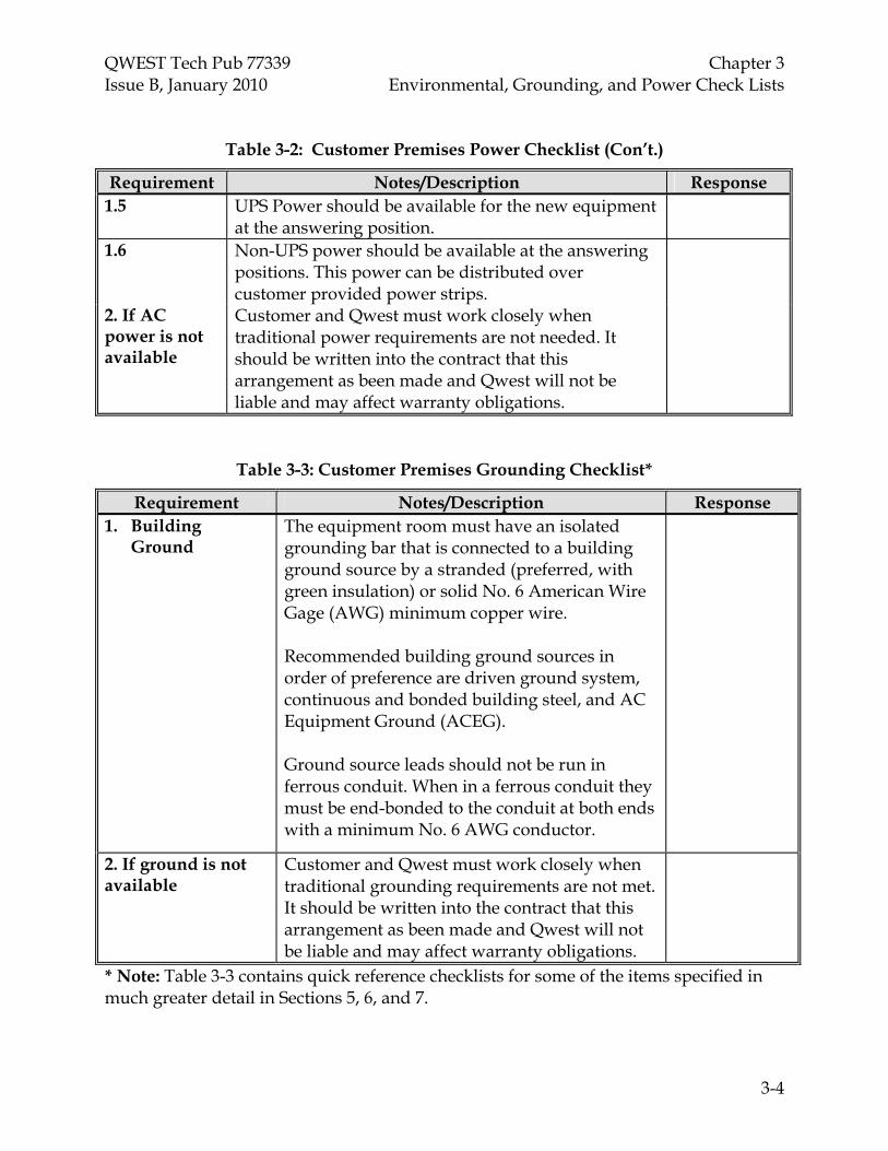
Table 3-2: Customer Premises Power Checklist (Con’t.)
Requirement Notes/Description Response 1.5 UPS Power should be available for the new equipment
at the answering position.
1.6 Non-UPS power should be available at the answering positions. This power can be distributed over customer provided power strips.
2. If AC power is not available
Customer and Qwest must work closely when traditional power requirements are not needed. It should be written into the contract that this arrangement as been made and Qwest will not be liable and may affect warranty obligations.
Table 3-3: Customer Premises Grounding Checklist*
Requirement Notes/Description Response 1. Building
Ground The equipment room must have an isolated grounding bar that is connected to a building ground source by a stranded (preferred, with green insulation) or solid No. 6 American Wire Gage (AWG) minimum copper wire. Recommended building ground sources in order of preference are driven ground system, continuous and bonded building steel, and AC Equipment Ground (ACEG). Ground source leads should not be run in ferrous conduit. When in a ferrous conduit they must be end-bonded to the conduit at both ends with a minimum No. 6 AWG conductor.
2. If ground is not available
Customer and Qwest must work closely when traditional grounding requirements are not met. It should be written into the contract that this arrangement as been made and Qwest will not be liable and may affect warranty obligations.
* Note: Table 3-3 contains quick reference checklists for some of the items specified in much greater detail in Sections 5, 6, and 7.

QWEST Tech Pub 77339 Chapter 4 Issue B, January 2010 Environmental Requirements
TOC 4-i
CONTENTS
Chapter and Section Page
4. Environmental Requirements ..................................................................................... 4-1 4.1 Facility Environmental Conditions, Upkeep, Storage and Handling ....... 4-1 4.2 Equipment Area Guidelines............................................................................ 4-2 4.3 Access Guidelines ............................................................................................ 4-3 4.4 Lighting Guidelines .......................................................................................... 4-3 4.5 Room Temperature and Humidity Guidelines ........................................... 4-4 4.6 Ventilation and Air Filtration Guidelines .................................................... 4-4
4.6.1 Air Quality Guidelines ......................................................................... 4-4 4.7 Floor Loading and Anchoring Guidelines .................................................... 4-5 4.8 Earthquake Zones and Equipment Ratings .................................................. 4-6 4.9 Fire Systems ....................................................................................................... 4-7
4.9.1 Fire Stopping Guidelines ..................................................................... 4-8 4.10 Asbestos Management Guidelines ................................................................. 4-84.11 Water/Flood Management Guidelines ......................................................... 4-8
Tables 4-1 Temperature and Humidity Requirements for Optimal Equipment
Operation ....................................................................................................................... 4-4
Figure 4-1 Earthquake Zone Map of the 48 Contiguous States................................................. 4-7

QWEST Tech Pub 77339 Chapter 4 Issue B, January 2010 Environmental Requirements
4-1
4. Environmental Requirements The environment is which E911 equipment technology resides must be maintained to proper conditions in order to minimize service outages and economically optimize the usable life of the equipment. These conditions encompass the construction of equipment space, installation, removal of equipment, and ongoing maintenance.
Qwest has recognized the need for a cleaner and more protective environment in the operating environment within which E911 equipment is deployed. Many operational problems, circuit failures, and service outages have been attributed to poor environmental conditions. These must be managed to minimize E-911 equipment failure. For optimal customer equipment operation, the requirements of the succeeding subsections should be met.
For purposes of this document, the term “Service Supplier” shall include any contractor or contracted agent doing work on a Customer’s Premises in behalf of Qwest (this includes Qwest’s own Local Network Operations (LNO) installation forces).
4.1 Facility Environmental Conditions, Upkeep, Storage, and Handling
If environmental concerns are being ignored, Qwest personnel may temporarily halt a job. The Premises owner (or their representative) may also halt a job if they have environmental concerns. Should a job be halted by either of the above for the stated reasons, the Qwest Sales Engineer should be contacted immediately.
All building construction or alterations within the areas requiring Service Supplier occupancy shall be completed before the scheduled start of the installation or removal activity. Any exceptions shall be subject to agreement between the Service Supplier, Customer Premises representatives, and Qwest representatives.
The Service Supplier and Qwest Sales Engineer shall negotiate with the PSAP Premises owner to provide suitable openings in buildings to allow material to be placed in position. The same process applies for necessary openings and ducts for cable and conductors in floors and walls as required.
The Service Supplier and Qwest shall discuss with the Premise owner the necessary ceiling inserts, embedded ceiling channel, or appropriate fastening arrangements in areas in which the equipment requires ceiling fastening.
The Service Supplier shall not adjust or disable any Heating, Ventilation, Air Conditioning (HVAC), humidity control, or building alarm system. Any necessary adjustments should be requested through the Premises Owner’s representative.
The Service Supplier shall be on site to receive and ensure proper storage of all material associated with their jobs. General cleaning of the equipment facility or storage area in which work is being done is to be performed by the Service Supplier during the entire installation or removal process. Care shall be taken to generate a minimal amount of airborne dust.

QWEST Tech Pub 77339 Chapter 4 Issue B, January 2010 Environmental Requirements
4-2
The Service Supplier shall not adjust or disable any Heating, Ventilation, Air Conditioning (HVAC), humidity control, or building alarm system. Any necessary adjustments should be requested through the Premises Owner’s representative.
The Service Supplier shall be on site to receive and ensure proper storage of all material associated with their jobs. General cleaning of the equipment facility or storage area in which work is being done is to be performed by the Service Supplier during the entire installation or removal process. Care shall be taken to generate a minimal amount of airborne dust.
4.2 Equipment Area Guidelines
Some equipment areas and/or locations offered by PSAPs, are unsuitable for the installation of Customer Premise E911 equipment. These types of locations/rooms are as follows:
• Near flammable materials including easily ignitable dusts and gases.
• Corrosive atmospheric or environmental conditions.
• Obstruction in work areas, passageways or other hazardous locations.
• Humid or moist areas.
• Flood-prone areas are highly discouraged and customer will be contractually responsible for any risk of loss.
• Avoid locations near high voltage transformers and high emission Radio Frequency (RF) devices.
• Near moving machinery.
• Heat, direct sunlight.
• Boiler rooms and/or Steam Pipes
• Washrooms
• Janitor's closet
In areas that Qwest considers unsuitable customer premises locations, unsafe or hazardous to the customer, their customers, or Qwest personnel, the customer will be required to make the appropriate changes to the space, or provide an alternate, acceptable, customer premise location before Qwest will place telecommunications equipment. As a general rule, there should be three feet of clearance in front of relay-rack mounted equipment for maintenance, and three feet behind relay-rack mounted equipment. Up to eighteen inches around the relay rack may be used for floor loading calculations and more information on floor loading) when there is no equipment located behind this bay. Customer Premises cabinets require three feet of maintenance clearance on both sides of

QWEST Tech Pub 77339 Chapter 4 Issue B, January 2010 Environmental Requirements
4-3
the cabinet, unless additional space is needed for heat dissipation or cooling for high power density bays.
If it is desired to place relay racks against a wall, all of the equipment and wiring mounted in those racks should be 100% accessible from the front. Some Customer Premises cabinets may be mounted against a wall if there is three feet of space in front of all cabinet doors. Some Customer Premise cabinets may require side access and a minimum of three feet is required.
For relay rack lineups that exceed twenty feet in length, the end aisle clearance on both ends should be at least 4 to 5 feet. This is a good idea even if the lineups do not exceed twenty feet.
4.3 Access Guidelines
As determined pre-sale, customer agrees to grant reasonable right of entry to Qwest's representatives to be able to respond to alarms, minimize service outage lengths, and ensure safe and reliable service. The customer is responsible for supplying all access for station, feeder, and riser cabling including where necessary:
• Conduit
• Floor boring
• Boring all major walls
• Access into hung ceilings, including removal and replacement of ceiling tiles
• Plywood and wall space or rack space for MDF and IDF locations
Each cabinet’s height, width, and depth must be accommodated. When mounted vertically, 12 inches of space MUST be allowed between cabinets. A minimum of 30" clearance is required in front of cabinet(s).
4.4 Lighting Guidelines
Sufficient lighting must be available in backroom equipment area. Lighting should not be obstructed. Emergency lighting should be available in case of power outage. If normal operating characteristics of available lighting emit high levels of Radio Frequency Interference (RFI) and/or Electro‐Magnetic Interference (EMI) other considerations should be made to avoid interference.
QWEST Tech Pub 77339 Chapter 4 Issue B, January 2010 Environmental Requirements
4-4
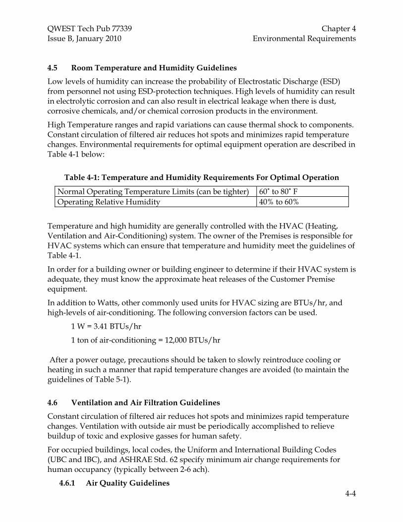
4.5 Room Temperature and Humidity Guidelines
Low levels of humidity can increase the probability of Electrostatic Discharge (ESD) from personnel not using ESD-protection techniques. High levels of humidity can result in electrolytic corrosion and can also result in electrical leakage when there is dust, corrosive chemicals, and/or chemical corrosion products in the environment.
High Temperature ranges and rapid variations can cause thermal shock to components. Constant circulation of filtered air reduces hot spots and minimizes rapid temperature changes. Environmental requirements for optimal equipment operation are described in Table 4-1 below:
Table 4-1: Temperature and Humidity Requirements For Optimal Operation
Normal Operating Temperature Limits (can be tighter) 60˚ to 80˚ F Operating Relative Humidity 40% to 60%
Temperature and high humidity are generally controlled with the HVAC (Heating, Ventilation and Air-Conditioning) system. The owner of the Premises is responsible for HVAC systems which can ensure that temperature and humidity meet the guidelines of Table 4-1.
In order for a building owner or building engineer to determine if their HVAC system is adequate, they must know the approximate heat releases of the Customer Premise equipment.
In addition to Watts, other commonly used units for HVAC sizing are BTUs/hr, and high-levels of air-conditioning. The following conversion factors can be used.
1 W = 3.41 BTUs/hr
1 ton of air-conditioning = 12,000 BTUs/hr After a power outage, precautions should be taken to slowly reintroduce cooling or heating in such a manner that rapid temperature changes are avoided (to maintain the guidelines of Table 5-1).
4.6 Ventilation and Air Filtration Guidelines
Constant circulation of filtered air reduces hot spots and minimizes rapid temperature changes. Ventilation with outside air must be periodically accomplished to relieve buildup of toxic and explosive gasses for human safety.
For occupied buildings, local codes, the Uniform and International Building Codes (UBC and IBC), and ASHRAE Std. 62 specify minimum air change requirements for human occupancy (typically between 2-6 ach).
4.6.1 Air Quality Guidelines

QWEST Tech Pub 77339 Chapter 4 Issue B, January 2010 Environmental Requirements
4-5
Accumulation of airborne contaminants on circuit boards can result in bridging of electrical and electronic circuits leading to circuit faults or intermittent failures. Contamination may be introduced by dust, textile fibers, human debris, soil contributions, products of combustion, etc.
4.7 Floor Loading and Anchoring Guidelines
Typically, Customer Premises types of sites (human-occupancy buildings) are designed for floor loading of 75 lbs/ft2 (psf). However, raised computer floors may not be able to support more than 50 lbs/ft2 (although they can be designed to support 300 lbs/ft2 or more if the floor underneath is rated for that).
Standard Vendor Customer Premises cabinets are generally designed for 75 lbs/ft2 floors with adequate spacing to the front and rear of the cabinet. If the cabinet is to be placed on a 50 lb/ft2 floor the weight of the cabinet and each of its individual components (especially if equipped with batteries) must be considered. In these cases it may not be possible to fully load the cabinet with equipment. However, if space is provided to the right and left of the cabinet (as well as in front and back), more equipment may be loaded into the cabinet.
Bottom basement slabs or ground floor on grade slabs typically have much higher floor loading capabilities (around 300 lbs/ft2), but this must be verified with the building owner. For concrete floors, individual point loading may exceed the average floor load allowed. However, the total floor load in a building bay (between support beams/walls) cannot exceed the limits for that bay. This is not true of raised floors, where point loading must be taken into consideration.
The Customer must tell Qwest Communications personnel what the floor loading of the space under consideration is. This information can generally be gleaned from the architectural and mechanical drawings of the building. If this information cannot be obtained, the following worst case floor loading capacities may be assumed:
• 150 lbs/ft2 for basement (or bottom floor) concrete floors
• 100 lbs/ft2 for concrete floors on other levels
• 50 lbs/ft2 for raised floors
• 75 lbs/ft2 for all other floors.
In a few instances, Customer Premises cabinets are wall-mounted. In these cases care must be taken to ensure that the wall can support the weight of the cabinet(s).
Hilti® item No.230712 anchor bolt assembly is recommended to be used when State/Local Codes/ NEBS requirements dictate (Refer also to Par. 7.2.6). The anchor has a 2-1/2 inch (70 mm) insertion depth and the head of the torque-indicating anchor will break off when installed correctly.

QWEST Tech Pub 77339 Chapter 4 Issue B, January 2010 Environmental Requirements
4-6
If floor depth or equipment design problems are encountered, the Service Supplier should contact the Sales Engineer for resolution. The service supplier should document the resolution and obtain a letter of deviation from the Sales Engineer.
4.8 Earthquake Zones and Equipment Ratings
It is important to ensure telecommunications equipment is properly braced to withstand the rigors of an earthquake. The reasons for this are threefold:
• Proper earthquake bracing helps ensure uninterrupted telephone service during a disaster such as an earthquake, and this is when communications services are most needed.
• Proper earthquake bracing helps keep potentially dangerous materials (e.g., batteries) from spills, leaks, etc., which would make them hazardous, and potentially toxic to humans.
• Proper earthquake bracing keeps equipment in place to prevent it from falling on humans.
Although traditionally not as much care has been given to ensuring that equipment in Customer Premises applications is earthquake-braced, the same reasons for having the bracing apply in this environment and perhaps with added urgency due to the importance of the telecommunications services and numbers of personnel at a typical Customer PSAP Premises installation.
Figure 4-1 shows the Earthquake Zones within the U.S. Zones 0 and 1 are the areas least likely to suffer an earthquake of any significance at all. Zone 2 denotes areas that could potentially suffer a mild earthquake. Zones 3 and 4 are for areas that could suffer violent earthquakes. Equipment designed to each of these standards is braced accordingly.

QWEST Tech Pub 77339 Chapter 4 Issue B, January 2010 Environmental Requirements
4-7
Figure 4-1: Earthquake Zone Map of the Contiguous 48 States
4.9 Fire Systems
The first few moments after a fire has started and/or is discovered are of extreme importance. Upon discovery of fire or smoke, immediately notify the building owner’s representative. If such a representative cannot be immediately found, call the Fire Department, and notify other building occupants.
The Equipment Floor Space must meet the local Fire Codes. The walls, floors, and doors should be a minimum of one-hour fire-rated. Fire detectors and alarms should be present. Usually none of this is a problem in Customer Premises spaces because these are generally designed for human occupancy and had to meet codes when built.
Although there is often not a choice in Customer Premises installations, if possible, space with a CO2 fire suppression system is much preferred over Halon or sprinklers. Water can harm the electrical components of telecommunications equipment. If sprinklers exist, see if it is a dry or non-pressurized system. If it is wet or pressurized, Qwest should notify building owner or tenet of risk associated from water damage caused by activation, leakage, etc. that could damage or destroy the equipment.
Customer and Qwest must work closely when traditional fire requirements are not needed. It should be written into the contract that this arrangement as been made and Qwest will not be liable and may affect warranty obligations. Fire, Life Safety Standards, Federal, State, or local regulations and/or codes take precedence.

QWEST Tech Pub 77339 Chapter 4 Issue B, January 2010 Environmental Requirements
4-8
4.9.1 Fire Stopping Guidelines
Fire-rated openings through which Qwest passes its cable (whether pre-existing or opened by Qwest in the installation process) in getting from the outside of the building to the inside will be fire-stopped per local fire codes. Qwest will reseal any fire-stopped openings that they open.
If the opening was not previously fire-stopped Qwest will assume that that passage does not constitute a passageway penetration per the locally adopted Fire Code. (Fire stop procedures, if needed, can be found in Qwest Technical Publication 77350 Iss. N Chapter 4).
4.10 Asbestos Management Guidelines
Customer agrees to certify that there is no asbestos on any premises in any areas where Qwest will be working. In the event Customer will not certify an asbestos-free environment or asbestos is discovered in the Qwest work area, there may be additional costs to perform in compliance with OSHA's rules and regulations.
4.11 Water/Flood Management Guidelines Telecommunications equipment does not function well in a wet environment. For this reason, if possible, space where there are sprinkler systems or water pipes above the potential equipment location should be avoided. If equipment is placed in a basement, all penetrations into the basement from outside the building should be properly sealed. It is also preferable in a basement installation that sump pumps and/or drains be present.

QWEST Tech Pub 77339 Chapter 5 Issue B, January 2010 Powering Guidelines
TOC 5-i
CONTENTS
Chapter and Section Page
5. Powering Guidelines .................................................................................................... 5-1 5.1 Essential AC Power from the Customer........................................................ 5-1 5.2 Operation without Backup Power.................................................................. 5-1

QWEST Tech Pub 77339 Chapter 5 Issue B, January 2010 Powering Guidelines
5-1
5. Powering Guidelines
This Section on Power addresses the general powering philosophy for Customer Premises sites.
5.1 Essential AC Power from the Customer
Qwest recommends the use of a customer provided Uninterruptible Power Supply (UPS) to maintain operations during this interruption of commercial AC power. UPS Power should be on the 911 CPE main system configurations as well as the workstation CPE/CPU’s etc. The customer should ensure essential HVAC system components are backed up by AC power in order to ensure that the temperature, humidity, and air quality guidelines defined in Section 4 can be met, even in the event of a commercial AC power outage. Unless otherwise specified in the contract, customer will be responsible for any charges associated with maintaining electricity, including any portion used by Customer Premise equipment as that equipment is owned and servicing the customer.
5.2 Operation without Backup Power
Customer and Qwest must work closely when traditional backup powering is not required. It should be written into the contract that this arrangement as been made and Qwest will not be liable and may affect warranty obligations.

QWEST Tech Pub 77339 Chapter 6 Issue B, January 2010 Grounding Guidelines
TOC 6-i
CONTENTS
Chapter and Section Page
6. Grounding Guidelines.................................................................................................. 6-16.1 General Grounding Information..................................................................... 6-16.2 Telecommunications Ground Collection Point ............................................ 6-26.3 Single Point Ground System ........................................................................... 6-3
6.3.1 (P) - Surge Producers............................................................................ 6-36.3.2 (A) - Surge Absorbers ........................................................................... 6-46.3.3 (N) - Non-Isolated Ground Plane (NON-IGP) Equipment Grounds ....... 6-46.3.4 (I) - Isolated Ground Plane (IGP) Equipment Grounds .................. 6-5 6.3.5 Main Distribution Frame (MDF) Data Rack Bonding & Grounding.... 6-6

QWEST Tech Pub 77339 Chapter 6 Issue B, January 2010 Grounding Guidelines
6-1
6. Grounding Guidelines
This Section addresses general grounding principles and offers guidelines on minimum ground wire sizes. Ultimately it is most desirable to keep impedance as low as possible among internal grounding cables to facilitate the flow of electrons back to ground and limit voltage differentials during a lightning strike or power fault to ground. A ground source is a point from which electrical current will see a low-impedance (resistance in the case of DC only) to ground. Per the National Electrical Code, this impedance should not exceed 25 Ω. Qwest Tech Pub 77355 prefers that it be lower than 5 Ω, although this is not always possible, depending on soil conditions, etc. Listed below are examples that qualify as good ground sources for Customer Premises locations.
• ACEG (The AC Equipment Ground is defined by the NEC as the “green-wire” ground run with AC circuits which is connected to the AC Neutral — and therefore to the electric company’s multi-grounded neutral — at the AC service entrance or House Service Panel. If the ACEG is used as the ground source, the connection should be made as close as possible to the HSP or nearest separately derived source. Failing that, the ACEG in the nearest AC panel will suffice.)
• AC Neutral (Absence of any of the above sources requires use of the AC Neutral. As with the ACEG, a connection to this ground source should be made at the House Service Panel or nearest separately derived source; however, it shall not be made to a neutral at an AC sub-panel. In fact, if any of the other ground sources above are used, they must have bonded electrical continuity all the way until there is a connection to the AC Neutral at the HSP).
Qwest requests that the customer extend at least one of these ground sources (with a cable sized according to the NEC, at a minimum of No. 6 AWG. It is also Code-required that the grounding cables running to the bar (both from the customer side and the Qwest side) have a green-colored insulation. The ground source from the Customer should not be run in ferrous metal conduit. If it is, it should be end-bonded at both ends of the conduit with a No. 6 AWG minimum. Typically, Qwest will collect all of its grounds to a single collection point (see section 6.3). From this point, a cable (appropriately sized per Tech Pub 77355, depending on the size of the installation) should be run between Qwest’s ground collection point and the ground bar that represents the extended building ground source. Failing the presence of a ground bar that is an extension of one of the ground sources, Qwest should interconnect its collection bar to one of the ground sources mentioned above
6.1 General Grounding Information
The desirable limit for any internal grounding path back to the building PGP is 0.03 ohms (up to 0.01 ohms on any one branch).
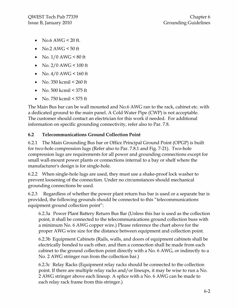
The following distances show the 0.01 ohm limit for the given stranded (preferred, with green insulation) or solid copper cable size:
QWEST Tech Pub 77339 Chapter 6 Issue B, January 2010 Grounding Guidelines
6-2
• No.6 AWG < 20 ft.
• No.2 AWG < 50 ft
• No. 1/0 AWG < 80 ft
• No. 2/0 AWG < 100 ft
• No. 4/0 AWG < 160 ft
• No. 350 kcmil < 260 ft
• No. 500 kcmil < 375 ft
• No. 750 kcmil < 575 ft
The Main Bus bar can be wall mounted and No.6 AWG ran to the rack, cabinet etc. with a dedicated ground to the main panel. A Cold Water Pipe (CWP) is not acceptable. The customer should contact an electrician for this work if needed. For additional information on specific grounding connectivity, refer also to Par. 7.8.
6.2 Telecommunications Ground Collection Point
6.2.1 The Main Grounding Bus bar or Office Principal Ground Point (OPGP) is built for two-hole compression lugs (Refer also to Par. 7.8.1 and Fig. 7-21). Two-hole compression lugs are requirements for all power and grounding connections except for small wall-mount power plants or connections internal to a bay or shelf where the manufacturer's design is for single-hole.
6.2.2 When single-hole lugs are used, they must use a shake-proof lock washer to prevent loosening of the connection. Under no circumstances should mechanical grounding connections be used.
6.2.3 Regardless of whether the power plant return bus bar is used or a separate bar is provided, the following grounds should be connected to this “telecommunications equipment ground collection point”:
6.2.3a Power Plant Battery Return Bus Bar (Unless this bar is used as the collection point, it shall be connected to the telecommunications ground collection buss with a minimum No. 6 AWG copper wire.) Please reference the chart above for the proper AWG wire size for the distance between equipment and collection point.
6.2.3b Equipment Cabinets (Rails, walls, and doors of equipment cabinets shall be electrically bonded to each other, and then a connection shall be made from each cabinet to the ground collection point directly with a No. 6 AWG, or indirectly to a No. 2 AWG stringer run from the collection bar.)
6.2.3c Relay Racks (Equipment relay racks should be connected to the collection point. If there are multiple relay racks and/or lineups, it may be wise to run a No. 2 AWG stringer above each lineup. A splice with a No. 6 AWG can be made to each relay rack frame from this stringer.)

QWEST Tech Pub 77339 Chapter 6 Issue B, January 2010 Grounding Guidelines
6-3
6.3 Single Point Ground System
The Single Point Ground System (SPGS) is a grounding philosophy that requires all major components of the Building Safety Protection System to be designed and bonded to a single ground reference point. These components consist of ground electrodes, grounding electrode conductors, grounded conductors, and grounding conductors. These conductors are designed to create the path of least resistance/impedance. This allows any voltage produced as current to flow or return to its source along the proper designated path. Connections to the SPGS will reduce voltage potential differences among various types of equipment. This should reduce personnel safety hazards, protect the equipment and reduce noise currents that may affect the operation of voltage-sensitive equipment. This includes equipment such as communication switching equipment and any computer controlled equipment. The SPGS has one main connection point. The single ground reference point is usually designated as the Main Grounding Bus bar (MGB). Different vendors may specify other titles for this single ground reference point. Carrying out the SPGS philosophy is simple yet very complex. The designated grounding conductors are methodically connected throughout the Building Safety Protection System within designated areas to the single ground reference point, or the Main Grounding Bus bar (MGB). Grounding conductors and their grounded components must be isolated from any unintended contact with other grounding conductors and grounded components except at the single ground reference point. Any unintended points of contact among different grounding conductors and components create ground loops within the SPGS and are violations of the SPGS. The Single Point Ground System (SPGS) Main Grounding Bus bar (MGB) is divided into sections (P-A-N-I), each containing designated conductor types. Each conductor connection attached to the Main Grounding Bus bar (MGB) should be tagged or stenciled to identify its point of origin. Single Point Grounding System (SPGS) Grounding conductors are divided into different categories and are arranged accordingly within the selected sections of the MGB. These sections are as follows:
6.3.1 (P) - Surge Producers
QWEST Tech Pub 77339 Chapter 6 Issue B, January 2010 Grounding Guidelines
6-4
Grounding conductors are expected to produce current. Different sources of surge energy include local lightning strikes, local commercial power surges, Electrostatic Discharges (ESD) from within the building, or any combination directed into the building on commercial AC service entrance conductors, telephone cables/pairs, or coaxial cables. Some examples of producer grounding conductors include:
Main Distribution Frame Bar (MDFB) Radio Frames Telephone Cable Entrance Ground Bar (CEGB) Telephone Cable Entrance Shields Transformer Frame Inside Building
6.3.2 (A) - Surge Absorbers
Absorber conductors are expected to absorb an energy surge and quickly return the voltage to its source. Absorber surge sources are usually AC or Electrostatic Discharge (ESD) voltages. Some examples of Absorber conductors include:
AC Power Entrance Multi-Grounded Neutral (MGN) Building Earth Ground System (BEGS) Building Structural Steel (BSS) Isolated AC Equipment Ground (ACEG) Metallic Conduit System Well Casing
6.3.3 (N) - Non-Isolated Ground Plane (NON-IGP) Equipment Grounds
Some buildings design the Non Isolated Ground Plane Ground Bar (Non-IGPB) that serves as a common collection point of grounding conductors serving the Non Isolated Ground Plane (NON-IGP). This Non Isolated Ground Plane Ground Bar (Non-IGPB) becomes a "window" to the actual Main Grounding Bus bar (MGB). The Non Isolated Ground Plane Ground Bar (Non-IGPB) MUST have a properly routed, bonded and sized grounding conductor connected directly to the Main Grounding Bus bar (MGB). Non Isolated Ground Plane (NON-IGP) grounding conductors are expected to quickly return all fault voltage to its source. In most Non Isolated Ground Plane (NON-IGP) areas some amount of fault current flow is expected, although not desirable. Non Isolated Ground Plane (NON-IGP) voltage is expected to be DC or Electrostatic Discharge (ESD) voltage. The Non Isolated Ground Plane (NON-IGP) section is also the connection point for

QWEST Tech Pub 77339 Chapter 6 Issue B, January 2010 Grounding Guidelines
6-5
equalizing voltages on the Reference DC power bus. This connection between the Reference DC power bus and the Main Grounding Bus bar (MGB) is not intended to be a DC power current carrying conductor and is provided only for equalizing voltage. Some examples of Non Isolated Ground Plane (NON-IGP) conductors include:
Battery Racks Intra Office Cable Shield Bar (IOCSB) Intra Office Cable Shields Main Distribution Frame (MDF) (-) Reference in a DC Power Plant with Negative Ground (+) Reference in a DC Power Plant with Positive Ground Storage Cabinets Transmission Frames Work Benches
6.3.4 (I) - Isolated Ground Plane (IGP) Equipment Grounds
Some buildings design an Isolated Ground Plane Bar (IGP-BAR) that serves as a common collection point for grounding conductors serving the Isolated Ground Plane (IGP). The Isolated Ground Plane Bar (IGPB) should be clearly stenciled or labeled and insulated from its support within the Isolated Ground Plane (IGP). This Isolated Ground Plane Bar (IGPB) becomes a "window" to the actual Main Grounding Bus bar (MGB). The Isolated Ground Plane Bar (IGPB) MUST have a properly routed, bonded and sized grounding conductor connected directly to the Main Grounding Bus bar (MGB). Isolated Ground Plane (IGP) areas should be clearly and permanently marked on the floor or in another easily recognizable manner. Paint or tape of a distinctive color such as orange is appropriate. The intent of an Isolated Ground Plane (IGP) is to isolate all voltage-sensitive equipment inside the Isolated Ground Plane (IGP) from any voltage event occurring outside the Isolated Ground Plane (IGP). This will prevent any event outside the Isolated Ground Plane (IGP) from causing any form of service outage to the voltage sensitive equipment inside the Isolated Ground Plane (IGP). Most buildings use an Isolated Ground Plane (IGP) for isolating voltage-sensitive equipment, such as a digital switch, from the rest of the equipment within the building. Some examples of Isolated Ground Plane (IGP) conductors include:
Isolated Ground Plane AC Equipment Ground (ACEG) Isolated Ground Plane Cable Runways Isolated Ground Plane Frame Return Bar (IGP-FRB) Isolated Ground Plane Logic Return Bar (IGP-LRB) Isolated Ground Plane Metallic Conduit Syste

QWEST Tech Pub 77339 Chapter 6 Issue B, January 2010 Grounding Guidelines
6-6
6.3.5 Main Distribution Frame (MDF) Data Rack Bonding and Grounding Procedure
The Electrical Contractor should provide the main grounding cable in the MDF/control room. Acceptable steps for providing minimal bonding and grounding requirements for customer premise MDF racks are described below.
Route the provided No. 6 AWG grounding cable from the grounding bus bar up and over the control room and across the data rack ladder-type cable rack to the data rack itself.
Minimize bends and turns when routing grounding conductor. Each data rack must be grounded to each adjacent data rack and/or cabinet
using two-hole compression lug in all MDF/control room installations. Two-hole crimp connectors shall be secured with an approved lock-washer placed between the connector and the head of the screw or nut.
Attach the last data rack ground to the main grounding conductor routed from the bus bar location. Be sure to attach the grounding conductor to the data rack itself.
All painted contact surfaces shall be cleaned so that metal-metal contact is made. A non-oxidizing agent shall be applied to inhibit corrosion.
The connection to the frame shall be made with a two-hole copper crimp connector.
Connections to grounding conductors shall be arranged to flow fault currents in the direction of the grounding source.
QWEST Tech Pub 77339 Chapter 7 Issue B, January 2010 Installation Guidelines
TOC 7-i
CONTENTS
Chapter and Section Page
7. Installation Guidelines..................................................................................................7-1 7.1 General Installation Guidelines and Requirements .....................................7-1
7.1.1 Facility Access and Security.................................................................7-2 7.2 Assembly and Ironwork...................................................................................7-2
7.2.1 Bolts, Nuts, Screws, and Threaded Rods ..........................................7-2 7.2.2 Cable Racks ............................................................................................7-3 7.2.2.1 Main Distribution Frame (Wall-Mounted) Ladder-Type Cable Rack .............................................................................7-3 7.2.3 Frames, Bays, Cabinets, and Stands....................................................7-4 7.2.3.1 Main Distribution Frame (MDF) Control Room.............7-4 7.2.4 Framework Parts ...................................................................................7-6 7.2.5 Mounting of Shelves/Equipment .......................................................7-6 7.2.6 Floor Anchors and Installation Instructions......................................7-6
7.3 Cabling: Forming, Running, and Securing ...................................................7-8 7.3.1 Cable Service Loop Requirements ......................................................7-9 7.3.2 Bending and Forming .........................................................................7-11 7.3.3 Cable Protection and Storage.............................................................7-11 7.3.4 Securing and Supporting....................................................................7-12 7.3.5 Cable Pileup .........................................................................................7-13 7.3.6 CAT 5e and Coaxial Cables................................................................7-13 7.3.7 Fiber Optic Cable Protective/Distribution Systems.......................7-13 7.3.8 Repair of Damaged Cables.................................................................7-14 7.3.9 Splicing Cables, and Mated Connectable Cables............................7-14 7.3.10 Use of Nylon and Plastic Cable Ties.................................................7-15
7.4 E-911 Operator/Position & Data Rack Wiring............................................7-15 7.4.1 Analog Circuits (2 or 4-Wire).............................................................7-16 7.4.2 Horizontal Cabling..............................................................................7-16 7.4.3 Work Station Outlet Wiring...............................................................7-16 7.4.4 Main Distribution Frame (MDF) Patch Panel Assembly (Method 1) ................................................................................................................7-17 7.4.5 Main Distribution Frame (MDF) Patch Panel Assembly (Method 2) ................................................................................................................7-18 7.4.6 MDF Rack Wire Management ...........................................................7-20 7.4.7 Patch Cord Color Guide and Dress Requirements.........................7-20 7.4.8 Wall Field and Integrations................................................................7-20 7.4.9 Wall Mounted Solution ......................................................................7-21

QWEST Tech Pub 77339 Chapter 7 Issue B, January 2010 Installation Guidelines
TOC 7-ii
CONTENTS (Continued)
Chapter and Section Page
7.4.10 Data Rack-Mounted Solution ............................................................7-22 7.4.10.1 110-Block and Patch Panel Application Integration........7-24 7.4.11 Centralized Automatic Message Accounting (CAMA) Trunk
Integration Interface Trunk Transfer................................................7-26 7.4.12 Administrative Line/Trunk Integration ..........................................7-26 7.4.13 Logging Voice Recorder (LVR) Connections ..................................7-27 7.4.14 Private Branch Exchange (PBX) Wall Field Layout........................7-27 7.4.15 MDF 110-Block Information .............................................................7-27 7.4.16 Point of Demarcation (DEMARC).....................................................7-27
7.5 Connecting........................................................................................................7-28 7.5.1 Crimp Compression Connectors, Splicing, and Taps ....................7-28 7.5.2 Quick Clip/Slotted Beam Connections............................................7-29
7.6 Equipment Designations ................................................................................7-29 7.6.1 Designation Conventions ...................................................................7-30
7.7 Power and Battery Installation Requirements and Guidelines ................7-32 7.7.1 DC Power Connections.......................................................................7-32 7.7.2 AC Circuit Installation........................................................................7-34
7..8 Proper Grounding Methods ..........................................................................7-34 7.8.1 Grounding Connections .....................................................................7-35 7.8.2 Grounding Conductors ......................................................................7-36 7.8.3 Isolated and Integrated Grounding Considerations ......................7-37
7.9 Hazardous Material Handling ......................................................................7-37 7.10 Installation Documentation ...........................................................................7-38
7.10.1 Commonly Used Installation/Removal Forms ..............................7-38 7.10.2 Job Packet and Job Log .......................................................................7-39 7.10.3 Job Completion or Exclusion Reporting ..........................................7-40 7.10.4 Service Interruption/Degradation Report.......................................7-40 7.10.5 Returning Material ..............................................................................7-40
7.11 Installation Methods of Procedure (MOP’s)................................................7-41 7.11.1 General MOP........................................................................................7-42 7.11.2 Detailed MOP.......................................................................................7-42 7.11.3 MOP Header Fields.............................................................................7-42 7.11.4 MOP Work Description Details.........................................................7-44 7.11.5 MOP Write-Up Review.......................................................................7-46 7.11.6 MOP Approval/Signing Authorities ...............................................7-46 7.11.7 Service Interruptions...........................................................................7-46

QWEST Tech Pub 77339 Chapter 7 Issue B, January 2010 Installation Guidelines
TOC 7-iii
CONTENTS (Continued)
Chapter and Section Page 7.12 Installation Checklist for Site Acceptance....................................................7-47
Tables Page
7-1 Cable Pile-up on Horizontal Cable Rack .................................................................7-13 7-2 Labeling Guidelines Checklist...................................................................................7-31 7-3 Common Installation/Removal forms.....................................................................7-38
Figures Page
7-1 Example of Wall-Mounted Ladder-Type Cable Rack..............................................7-3 7-2 Examples of Data Rack Placement..............................................................................7-4 7-3 Properly-Installed Server, Monitor, and Keyboard Shelf........................................7-5 7-4 Bay Floor Anchor Placement Scheme.........................................................................7-7 7-5 Example of Cable Vertical Transition with Chain Support.....................................7-9 7-6 Example of a Proper Waterfall Installation and Supported Cable Bundles .........7-9 7-7 Example of IDF Service Loop ....................................................................................7-10 7-8 Example of Work Station Service Loop....................................................................7-11 7-9 Typical Work Station Outlet Assembly....................................................................7-17 7-10 Example of an RJ45 Unloaded Patch Panel with Jacks ..........................................7-17 7-11 Examples of RJ45 Fully-Loaded 24/48-Position Patch Panel with Jacks ............7-18 7-12 Example of Properly-Installed MDF Patch Panel Assembly ................................7-19 7-13 Example of Dual-Rack Unit Wire Managers Assembly.........................................7-20 7-14 Wall-Mounted Solution Example..............................................................................7-22 7-15 Data Rack-Mounted Solution ....................................................................................7-23 7-16 Example of a 110-Block with Multiple Point Connections....................................7-24 7-17 Example of a 110-Block-to-Patch Panel ....................................................................7-25 7-18 Example of a CAMA Trunk Interface.......................................................................7-26 7-19 Example of ADMIN Line/Trunk Integration .........................................................7-26 7-20 Example of LVR Connection......................................................................................7-27 7-21 Two-Hole Crimp Connector ......................................................................................7-36 7-22 Installation Check List for Site Acceptance .............................................................7-48 7-23 RG 47-0163 Detailed Method of Procedure (DMOP) for E-911
Installation/Removal/Modifications.......................................................................7-52 7-24 RG 47-0013 Service Degradation Report..................................................................7-60

QWEST Tech Pub 77339 Chapter 7 Issue B, January 2010 Installation Guidelines
7-1
7. Installation Guidelines
Installation requirements and guidelines for Customer Premises equipment space cannot be as strict as those applied to Qwest-owned space, simply because Qwest does not own the space. For purposes of this section (and the entire document), the following terms denote whether a requirement is absolute (must be met) or not (these same definitions can be found in Section 2.1):
• SHALL, MUST — denotes requirements which must be adhered to for basic personnel safety and basic reliability
• SHOULD, ADVISABLE, DESIRABLE — guidelines which would improve reliability and safety, but do not have to be absolutely followed (suggestions)
7.1 General Installation Guidelines and Requirements
This document provides Service Suppliers with the general requirements affecting building facilities and their care, the installation and removal of telecommunications equipment, and related service requirements to be met prior to such activities. For purposes of this document, the term “Service Supplier” shall include any contractor or contracted agent doing work on a Customer’s Premises in behalf of Qwest (this includes Qwest’s own Installation forces).
This document also provides key material and workmanship requirements for Engineering and Service Suppliers and shall be a basis for audit and evaluation of a job. The workmanship items described in this section are both generic and specific in nature and may be applicable to all installation and removal operations. In addition, the Service Supplier shall adhere to the specific installation (new or reuse), removal, and operational standards established in applicable equipment specifications as well as all handbooks and technical information required to successfully complete installation or removal of the equipment.
Service Suppliers doing business with Qwest for a product type shall show a level of expertise in that technology, based on history, training, or related work experience. Service Suppliers shall be required to comply with all suppliers’, manufacturers’, and Qwest Standards and configurations. Lack of documentation or information is not an acceptable reason for noncompliance with this Standard. The Service Supplier shall be responsible for providing all tools and expendable materials necessary to complete the job.
When a Service Supplier becomes aware of a preexisting defective condition, that impacts the work on the job they are installing or removing; the Service Supplier shall contact the Qwest Sales Engineer and take corrective action if authorized. All activity shall be documented.
Any questions not answered by this section, the job specifications, drawings/records, etc. shall be referred to the Qwest Sales Engineer for resolution and documented in the job log by the Service Supplier.

QWEST Tech Pub 77339 Chapter 7 Issue B, January 2010 Installation Guidelines
7-2
7.1.1 Facility Access and Security
The Service Supplier shall be in the facility only during authorized scheduled work hours as agreed to and defined in the Statement of Work (SOW). Depending on the location, Service Suppliers may also need to inform or obtain permission from the Premises owner (or their authorized representative, such as a guard or building maintenance personnel) each time they enter or leave a facility. The Service Supplier shall determine these requirements with the Premises owner before beginning installation activity.
7.1.1a The Qwest Sales Engineer and Premise Owner will jointly be responsible for the security of the installation materials and equipment.
7.1.1b The Service Supplier shall be responsible for the security of their personal valuables, tools, materials, and the parking of private and company vehicles.
7.1.1c The Service Supplier shall not bring alcohol, drugs, firearms, weapons, or explosives into any Customer Premises facility.
7.2 Assembly and Ironwork
The location of auxiliary framing, cable racks, frames, relay racks, bays, cabinets, and other equipment should conform to any particular plans, drawings, records, and specifications for each installation that are provided by the engineer. If equipment must be placed in a different position than that shown in the drawings, the Service Supplier shall note the “as-built” configuration on the drawings, and send these to the Qwest Sales Engineer. All assemblies and ironwork referred to in this section should be installed to meet Seismic zone requirements for the area in which they are installed. Overhead clearance in all aisles and equipment areas should typically be maintained at a minimum height of 7 feet. This includes auxiliary framing, cable rack, cableway systems and lighting.
7.2.1 Bolts, Nuts, Screws, and Threaded Rods
7.2.1a All installer-mounted units shall be secured with a minimum of four screws in the upper and lower most available mounting holes on each side of the unit. Units exceeding 8 inches in height require 1 additional mounting screw on both sides for each additional 8-inch interval. Additional screws may be required for heavier units or as required by manufacturers' specifications.
7.2.1b All bolts, nuts and screws used to secure any part shall be inserted in their respective mounting holes, be tightened and, free of damage.
7.2.1c All threads of a nut must be used. Bolts/screws may protrude beyond the nut, but not to the extent that they would create a safety or service hazard. Maximum

QWEST Tech Pub 77339 Chapter 7 Issue B, January 2010 Installation Guidelines
7-3
allowable protrusion, where exposure may create a safety or service hazard, shall not exceed the diameter of the threaded unit.
Both ends of bolts, screws or threaded rods shall be free of sharp edges.
7.2.2 Cable Racks
7.2.2a All cable racks shall be of the proper size and type, and located, leveled and aligned per job specification and drawing.
7.2.2b Cable rack runs consisting of one piece of cable rack require a minimum of two points of support for each stringer.
7.2.2c All sections of cable rack shall have both stringers supported at a minimum of one point, regardless of length. Vertical cable rack shall be supported with a minimum of two supports. Stringer splices do not constitute a support.
7.2.2d Maximum distance between supports should not exceed six feet (standard spacing is 5-0”. The distance between last supports and cable rack ends should not exceed three feet. Sections of cable rack four feet or less in length may be supported by two corner clips at each end.
7.2.2e Open and protruding ends of ladder type cable rack shall be finished with closing details or protective rubber caps. All splices, junction details, brackets, and hangers shall be secure and installed per standard convention.
7.2.2.1 Main Distribution Frame (Wall-Mounted) Ladder-Type Cable Rack When an overhead, 7-0’ ladder-type cable rack is installed to an adjacent wall (with an angle support bracket) per Figure 7-1, the acceptable distance between the wall and the data rack should be a minimum of 2-0’ to ensure an unobstructed pathway to the wall for cable running and cable rack support.
Figure 7-1: Example Wall-Mounted Ladder-Type Cable Rack
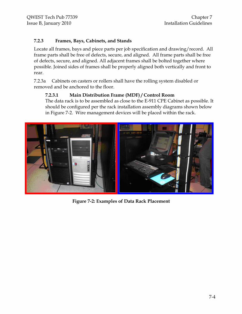
QWEST Tech Pub 77339 Chapter 7 Issue B, January 2010 Installation Guidelines
7-4
7.2.3 Frames, Bays, Cabinets, and Stands
Locate all frames, bays and piece parts per job specification and drawing/record. All frame parts shall be free of defects, secure, and aligned. All frame parts shall be free of defects, secure, and aligned. All adjacent frames shall be bolted together where possible. Joined sides of frames shall be properly aligned both vertically and front to rear.
7.2.3a Cabinets on casters or rollers shall have the rolling system disabled or removed and be anchored to the floor.
7.2.3.1 Main Distribution Frame (MDF) / Control Room The data rack is to be assembled as close to the E-911 CPE Cabinet as possible. It should be configured per the rack installation assembly diagrams shown below in Figure 7-2. Wire management devices will be placed within the rack.
Figure 7-2: Examples of Data Rack Placement

QWEST Tech Pub 77339 Chapter 7 Issue B, January 2010 Installation Guidelines
7-5
Figure 7-3: Properly-Installed Server, Monitor, and Keyboard Shelf.
QWEST Tech Pub 77339 Chapter 7 Issue B, January 2010 Installation Guidelines
7-6
7.2.4 Framework Parts
7.2.4a All piece parts (i.e., ironwork, framework, threaded rod, miscellaneous details, etc.) should be installed per equipment drawings/records and shall be secure, aligned, plumb, and free from defects, sharp burrs, points, etc.
7.2.4b All surfaces of equipment and ironwork parts should be free of rust, dirt and contaminants. If rust is apparent on equipment or parts, they should be cleaned and painted.
7.2.5 Mounting of Shelves/Equipment
7.2.5a All units of equipment shall not extend beyond the front or rear edges of the base of the frame. The installer shall notify the Sales Engineer when this cannot be accomplished and provide a detailed description in the job log. The Sales Engineer must acknowledge the deviation.
7.2.5b Mounting space adapters shall be used where the fabricated hole spacing is incorrect for the equipment being mounted in the frame, bay, or cabinet. The frame, bay or cabinet shall not be drilled to accommodate equipment mounting.
7.2.5c When bays are up against a wall or back up to other equipment in a cabinet so that rear access is near impossible, every effort should be made to install only front-accessible equipment. Where equipment is wall-mounted, it generally should not be mounted above 7-0’.
7.2.6 Floor Anchors and Installation Instructions
For anchor bolt quantity and positioning information refer to Figure 7-4 “Bay Anchor Placement Scheme” (p. 7-7). These anchor assemblies are preferred. If floor depth or equipment design problems are encountered, the Service Supplier should contact the Sales Engineer for resolution.
Floor Anchor Installation Instructions are as follows (when manufacturer instructions are not available):
• Drill the proper diameter and depth hole following the instructions in the previous Section as appropriate.
• Clean loose debris from the hole. Make sure all drilling debris is removed from the hole.
• Make sure the nut and washer are threaded onto the rod with the washer in contact with the top of the sleeve. Any isolation bushings or hold down plates should not be on the anchor at this time.
• Insert the anchor into the hole and tap the anchor down with a hammer until the washer contacts the concrete.

QWEST Tech Pub 77339 Chapter 7 Issue B, January 2010 Installation Guidelines
7-7
• Pre-torque the anchor to approximately one half of its installation torque (30 foot pounds).
• Loosen the nut several turns and then remove the rod, nut, and washer. The rod assembly may be backed out by using the screwdriver slot.
• Position the frame, bay, or cabinet over the holes. Be careful not to let debris fall into the holes.
• Place the rod through the hole in the base of the frame, bay, or cabinet and thread it into the anchor body until it is fully engaged in the threads in the bottom cone.
• Add all components such as bushings, washers, and hold down plates.
• For Hilti™ anchors, tighten the torque nut to the point where the top flange of the nut snaps off (approximately 60 foot pounds). Use a box end or a flare nut wrench or socket to tighten the torque nut. Do not use an open-end wrench, which may distort the torque nut and affect the setting torque.
When mounting frames, bays, and cabinets on raised floor environments, the floor manufacturer’s instructions for mounting shall be followed, and the appropriate number of anchors should be used for the seismic zone in which the equipment is located.
In raised floor environments where the space underneath the floor is used as an air plenum, all cables placed in this space must be plenum-rated (or placed in fire-resistant conduit), or the room must be classified as “IT” space (with accompanying special restrictive requirements), per the NEC.
Figure 7-4: Bay Floor Anchor Placement Scheme

QWEST Tech Pub 77339 Chapter 7 Issue B, January 2010 Installation Guidelines
7-8
7.3 Cabling: Forming, Running, and Securing 7.3a Route cables to avoid pileups and blocking of cable runs. All cables shall be run within the confines of the cable rack stringers. Do not run cables on existing cable racks where cable pileup exceeds the top of cable horns. Routing of cables on the equipment floor without using the overhead constructed cable management system is prohibited.
7.3b Cables shall be typically run directly, from point to point, with only a maintenance loop of slack (not to exceed 4 feet) stored on the cable rack. Although not generally encouraged, it is permissible to run cable between adjacent bays/cabinets without going above or below the rack. In "Heavy" Earthquake Zones, cabling between equipment elements that are secured to different earthquake planes (i.e. floor and ceiling) shall require additional slack between the cable break off and the equipment frame. Typically an additional 9- inch slack loop shall be provided.
7.3c At any point where the cable routing of (6) or more cables must be run on an extended vertical drop of more than three feet without a cable racking support structure in place, an acceptable method of transition can be accomplished by means of the following options:
• A support chain (Refer to Figure 7-5) fastened to the Customer Premise building structure attached via No. 9 lacing cord form stitching or suitable hook & loop straps properly sized for the intended cable bundle application.
• The use of 4” Poly-Vinyl Chloride (PVC; non-plenum environment) pipe or a section of 4” metal conduit (plenum environment) as a strain relief mechanism. This method is accomplished by attaching the material to be used in a horizontal manner, removing any wire ties around cable bundles to allow the wires to fan out. Carefully route the cable over the curved edge of the support material allowing the support material to bear the weight of the cables as they make the vertical drop. (Refer to Figure 7-5). Questions regarding the use of this type of waterfall support should be directed to the Qwest Sales Engineer.

QWEST Tech Pub 77339 Chapter 7 Issue B, January 2010 Installation Guidelines
7-9
Figure 7-5: Example of Cable Vertical Transition with Chain Support.
Figure 7-6: Example of a Proper Waterfall Installation and Supported Cable Bundles.
7.3.1 Cable Service Loop Requirements
7.3.1a As per Building Consulting Services, International (BICSI), where cable service loops are required to permit future cable system changes, e.g.; cable racking

QWEST Tech Pub 77339 Chapter 7 Issue B, January 2010 Installation Guidelines
7-10
system rework Ten (10) feet of voice and data cable slack should be located above the Control Room Main Distributing Frame (MDF) to allow cable slack to be stored below the building structure (utilizing the wall-mounted; ladder-type cable rack above the ceiling).
Note: If installation above the MDF is not possible, the Service Supplier will contact the Qwest Sales Engineer for further instruction.
7.3.1b The service loop at the Intermediate Distributing Frame (IDF) is normally located above the dropped ceiling in the sales floor area just outside the penetration to the storeroom IDF location or on the building structure above the remote rack (Refer to Figure 7-7). Utilize a figure eight configuration on j-hooks to store slack for all IDF service loops.
7.3.1c The Service Supplier will have separate bundles for the voice, data and fiber backbone, as needed, to not overfill the cable support system. These cable bundles will be placed in approximately one-foot diameter loops. The cable will only cross itself once. This design is a recommendation based on tests by the cable manufacturer to minimize return loss and cross talk. Also, the Service Supplier will place a third support at the point the bundle will drop down towards the IDF.
Figure 7-7: Example of IDF Service Loop
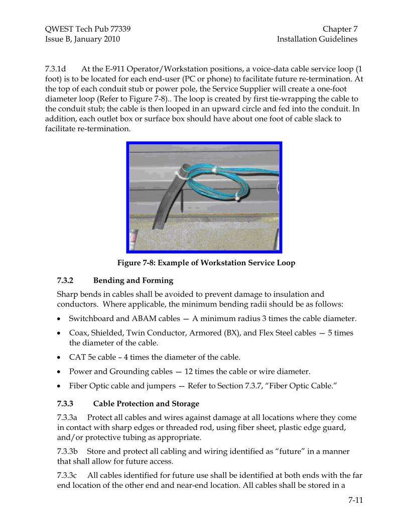
QWEST Tech Pub 77339 Chapter 7 Issue B, January 2010 Installation Guidelines
7-11
7.3.1d At the E-911 Operator/Workstation positions, a voice-data cable service loop (1 foot) is to be located for each end-user (PC or phone) to facilitate future re-termination. At the top of each conduit stub or power pole, the Service Supplier will create a one-foot diameter loop (Refer to Figure 7-8).. The loop is created by first tie-wrapping the cable to the conduit stub; the cable is then looped in an upward circle and fed into the conduit. In addition, each outlet box or surface box should have about one foot of cable slack to facilitate re-termination.
Figure 7-8: Example of Workstation Service Loop
7.3.2 Bending and Forming
Sharp bends in cables shall be avoided to prevent damage to insulation and conductors. Where applicable, the minimum bending radii should be as follows:
• Switchboard and ABAM cables — A minimum radius 3 times the cable diameter.
• Coax, Shielded, Twin Conductor, Armored (BX), and Flex Steel cables — 5 times the diameter of the cable.
• CAT 5e cable – 4 times the diameter of the cable.
• Power and Grounding cables — 12 times the cable or wire diameter.
• Fiber Optic cable and jumpers — Refer to Section 7.3.7, “Fiber Optic Cable.”
7.3.3 Cable Protection and Storage
7.3.3a Protect all cables and wires against damage at all locations where they come in contact with sharp edges or threaded rod, using fiber sheet, plastic edge guard, and/or protective tubing as appropriate.
7.3.3b Store and protect all cabling and wiring identified as “future” in a manner that shall allow for future access.
7.3.3c All cables identified for future use shall be identified at both ends with the far end location of the other end and near-end location. All cables shall be stored in a

QWEST Tech Pub 77339 Chapter 7 Issue B, January 2010 Installation Guidelines
7-12
manner that allows for future access. Cables run (extended), but not yet connected, shall be coiled, banded, and stored (outside the rack) in a safe manner.
7.3.3d All cables shall have their exposed ends covered (taped) during the running process (and until they are terminated) to protect existing equipment.
7.3.3e All types of cable rack that have threaded rod(s) in contact with the cable rack, shall have the threaded rod(s) protected with protective tubing.
7.3.3f Provide protection using sheet fiber paper on inverted ladder-type cable rack in a horizontal or vertical plane where the wire and cable are in contact with the flange side of the cross straps. Power wires fastened to the underside of channel type cable rack straps shall be protected.
7.3.3g All soft rubber-insulated cables require protection when secured with No. 9 cord, or hook & loop equivalent. Cable insulation that will not “cold-flow” is exempt from this requirement. Cold flow is a condition where insulation thins or flows away from an impingement point.
7.3.3h All exposed ends of power or grounding cables shall be protected with plastic electrical tape or heat shrinkable end caps. This requirement applies specifically to common feeders serving multiple bays or cables that have been dead ended.
7.3.4 Securing and Supporting
7.3.4a It is preferred that all cables and wires not in basket-type or panned cable rack be secured with No. 9 cord, or a suitable hook & loop equivalent, at cable rack break-off points, banded or tied between the cable rack and first support (where this distance exceeds eighteen inches), and banded or tied at the first support on a frame, bay, or cabinet.
7.3.4b Horizontal runs are to be sewn every sixth strap and when necessary to keep cable in the cable rack or from sagging through the cable rack. Vertical runs (and waterfall rack) are sewn on every alternate strap. No more than two square inches of cable shall be secured under a single stitch.
7.3.4c Where cables extend from a ceiling supported racking system to equipment frames that are floor-supported only or not physically connected to the feeder rack, an additional 9-inch slack loop shall be provided.
7.3.4d At the point of break-off the cable rack stringer (side of the cable rack) shall be protected with a wrap of sheet fiber paper or equivalent.
7.3.4e Secure and support all cables before, at, and after turns or junctions of horizontal runs in other than pan, basket, and horned racks. Cable should not be unsupported for a distance greater than three feet, measured from the last support on the cable rack or waterfall to the first support on the frame, bay, or rack, except where otherwise specified in specifications or drawings.
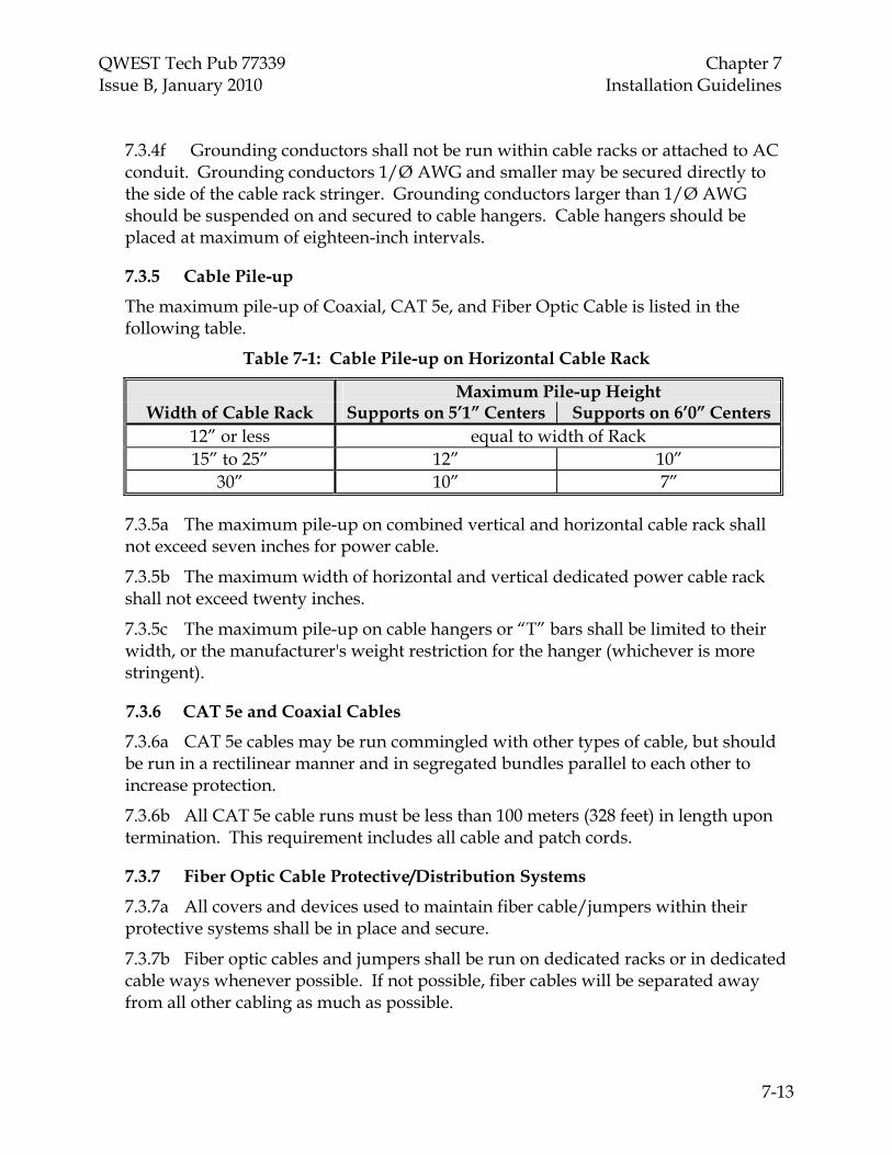
QWEST Tech Pub 77339 Chapter 7 Issue B, January 2010 Installation Guidelines
7-13
7.3.4f Grounding conductors shall not be run within cable racks or attached to AC conduit. Grounding conductors 1/Ø AWG and smaller may be secured directly to the side of the cable rack stringer. Grounding conductors larger than 1/Ø AWG should be suspended on and secured to cable hangers. Cable hangers should be placed at maximum of eighteen-inch intervals.
7.3.5 Cable Pile-up
The maximum pile-up of Coaxial, CAT 5e, and Fiber Optic Cable is listed in the following table.
Table 7-1: Cable Pile-up on Horizontal Cable Rack
Maximum Pile-up Height Width of Cable Rack Supports on 5’1” Centers Supports on 6’0” Centers
12” or less equal to width of Rack 15” to 25” 12” 10”
30” 10” 7”
7.3.5a The maximum pile-up on combined vertical and horizontal cable rack shall not exceed seven inches for power cable.
7.3.5b The maximum width of horizontal and vertical dedicated power cable rack shall not exceed twenty inches.
7.3.5c The maximum pile-up on cable hangers or “T” bars shall be limited to their width, or the manufacturer's weight restriction for the hanger (whichever is more stringent).
7.3.6 CAT 5e and Coaxial Cables
7.3.6a CAT 5e cables may be run commingled with other types of cable, but should be run in a rectilinear manner and in segregated bundles parallel to each other to increase protection.
7.3.6b All CAT 5e cable runs must be less than 100 meters (328 feet) in length upon termination. This requirement includes all cable and patch cords.
7.3.7 Fiber Optic Cable Protective/Distribution Systems
7.3.7a All covers and devices used to maintain fiber cable/jumpers within their protective systems shall be in place and secure.
7.3.7b Fiber optic cables and jumpers shall be run on dedicated racks or in dedicated cable ways whenever possible. If not possible, fiber cables will be separated away from all other cabling as much as possible.
QWEST Tech Pub 77339 Chapter 7 Issue B, January 2010 Installation Guidelines
7-14
7.3.7c A dedicated cable slot/hole/sleeve should be used for fiber cable entering the equipment facility from the CEF with provisions for approved fire/smoke and gas stopping.
7.3.7d Fiber optic cable and jumpers shall not be pulled, kinked or twisted during installation. Manufacturers' guidelines shall be followed.
7.3.7e Fiber optic cable slack in the trough system or on cable rack shall not exceed the maintenance loop (4-foot) maximum length (coiling or storing excessive slack in a cable rack or trough is strictly prohibited).
7.3.7f Cable ties shall not be used for banding or securing fiber optic cables/jumpers.
7.3.7g Fiber optic cable bend radius shall not be less than 2.5" for simplex cables. Consult the cable manufacturer's guidelines for the larger bending radii of fiber cables with more fibers. The default bending rule is 10 times the diameter of the cable.
7.3.8 Repair of Damaged Cables
7.3.8a Damaged outer jackets of Polyvinyl Chloride (PVC) covered cables shall be repaired with electrical tape and/or heat shrink tubing. The tape shall be applied in two half-lapped layers with the final two wraps applied without tension and overlapping. The tape shall extend a minimum of two inches past the damaged section.
7.3.8b Seriously damaged sections of outer jackets of PVC covered cables shall be repaired by removing the damaged section and replacing it with the covering from a similar cable. Apply a single half-lapped layer of electrical tape over the new section, extending two inches either side of the repaired section, to secure it in place.
7.3.8c Damaged power cable insulation shall be repaired with an insulation equivalent to that of the original, or with an insulating device identified for the purpose (heat shrink tubing is acceptable).
7.3.8d A run of cable shall be replaced if the number of damaged conductors exceeds five percent of total conductors.
7.3.9 Splicing Cables, and Mated Connectable Cables
7.3.9a Multi-conductor cable shall be rerun if the number of spliced conductors exceeds five percent of the conductors in the cable. Under certain conditions, this requirement may be deviated from with permission of the Qwest Sales Engineer. A letter of variance shall be required and the reason shall be documented in the job log.
7.3.9b Splicing of cables shall be kept to a minimum and, if required, shall generally be done in the vertical duct of frames, bays or cabinets. All splices shall be protected (grounding splices are not required to be insulated, and are only required to be protected if they have sharp edges in a position to cut other cables). Splices shall not appear on the cabling surface of cable racks (power splices are exempt from this rule).

QWEST Tech Pub 77339 Chapter 7 Issue B, January 2010 Installation Guidelines
7-15
7.3.9c Mating of connectable cables shall be kept to a minimum and if required shall be done in the vertical duct on the splice shelf of frames, bays, or cabinets, or on dedicated rack. Connectors shall not appear on the cabling surface of a cable rack.
7.3.9d Mated connectable cables shall be mated and secured by using twine, tie wraps, hook and loop systems, screws, spring clips, etc.
7.3.9e Spliced or mated cables shall be protected, designated, and accessible for maintenance.
7.3.9f Protective covers or caps shall be installed on unused connectors to protect contacts from mechanical or ESD damage.
7.3.10 Use of Nylon and Plastic Cable Ties
7.3.10a Cable ties are not approved for securing fiber optic cables and jumpers.
7.3.10b Cable ties used for banding and securing of CAT5e cables, PVC protection etc. shall be of an adequate size, type, strength, etc. for the particular application.
7.3.10c Mating Cable ties shall be trimmed at the locking head with a flush-cutting device that provides automatic tensioning. Under no circumstances shall cable ties have sharp or jagged cut ends protruding from the locking head. A cable tie is considered to have sharp or jagged ends when it is sharp to the touch.
7.3.10d The locking head of reusable cable ties shall be positioned so as not to interfere with the installation or removal of apparatus or equipment (i.e., towards the outside or bottom of a rack, brace, etc.)
7.3.10e Reusable cable tie tails shall be positioned so as not to present a personnel hazard.
7.3.10f When installing additional cable or wire to forms, the existing cable ties shall be removed where the heads of tie wraps interfere with additional cable or wires.
7.3.10g Where cable or wire forms are secured to cable securing brackets, the locking head of the cable tie-wrap shall be positioned on the side of the bracket opposite the side on which the cables or wires are run.
7.4 E-911 Operator/Position & Data Rack Wiring
Wire shall be of the type, color, and gauge specified in the drawings/records and/or manufacturer's specifications and instructions. 7.4a Respectively, all cabling must be treated as a data cable, capable of 100MHZ. Properly-terminated jacks (RJ45, 568B) and 110-style patch panels will serve as the termination points, data cross-connect will be accomplished by patch cords. Wire shall be dressed in such a manner as to avoid congestion, to ensure accessibility, and to maintain clearance between terminals.

QWEST Tech Pub 77339 Chapter 7 Issue B, January 2010 Installation Guidelines
7-16
7.4b All spare and unused wire shall be placed in fiber/protective tubing or secured to the existing form or equipment. Individual bare wire ends shall be insulated. This requirement shall also apply to spares within a frame distribution block enclosure.
7.4c Wires connected in distribution frame blocks shall be dressed to allow visual inspection of terminal connections. Wires shall be run as directed in the manufacturer’s specifications and records/drawings.
7.4d Wire dress shall be sufficient to provide for one additional skinner length without splicing the conductor. All wiring shall be protected from hazardous conditions such as sharp edges, excessive strain, etc.
7.4e All installation cable running tags shall be removed prior to job completion and turnover. Factory-installed shop wiring and verification tags designed for proper interconnection of bay equipment are not considered cable running tags and will not be removed at the completion of testing and turn-up.
7.4.1 Analog Circuits (2 or 4-Wire) Analog circuits (2 or 4-wire) can be introduced to the patch panels via 110-type connecting blocks wired to patch panels. The cross-connecting is accomplished via patch cords.
7.4.2 Horizontal Cabling The Miscellaneous Materials list provides several options for cabling as follows:
The patch panel location must be defined prior to cable installation. Considerations must include the location of the panel with relationship to the E-911 CPE equipment.
Ideally the size of the installation will determine where the panels will go. In a small PSAP the patch panel may fit in the Vendor cabinet, if not a wall mount bracket and 19” rack are available.
A multiple selection of patch cords in varied lengths are available up to 25 feet for the physical layer connection.
7.4.3 Work Station Outlet Wiring
The termination point for these cables is a 4-port surface jack assembly. The jacks are color-coded to align with the designated cable colors. The jacks are 568B terminated with a 110 blade. Positioning of these connectors should be per Figure 7-9 as indicated:
Voice 1 - White Voice 2 - Gray or Blank Data 1 - Blue

QWEST Tech Pub 77339 Chapter 7 Issue B, January 2010 Installation Guidelines
7-17
Data 2 - Yellow
Figure 7-9: Typical Work Station Outlet Assembly
7.4.4 Main Distribution Frame (MDF) Patch Panel Assembly (Method 1)
A blank MDF patch panel is available in 12, 24, and 48-position ports (Refer to Figure 7-11). This panel is designed to fit a standard 19” relay rack or can be wall-mounted with an associated wall mounting bracket assembly. This panel is designed to be equipped (from left to right) with RJ45 jacks assigned to each vacant port position. This scheme aligns with the same wiring method outlined in Par. 7.4.3. At each work station/position, (4) ports are dedicated for use (two assigned; and two vacant positions for future voice/LVR recording capability).
Figure 7-10: Example of an RJ45 Unloaded Patch Panel with Jacks (1 of 2)

QWEST Tech Pub 77339 Chapter 7 Issue B, January 2010 Installation Guidelines
7-18
Figure 7-10: Example of an RJ45 Unloaded Patch Panel with Jacks (2 of 2)
7.4.5 Main Distribution Frame (MDF) Patch Panel Assembly (Method 2)
In Figure 7-10, the Patch Panel is fully-equipped or “loaded” with jacks and 110 quick-clip, slotted-beam (referred to as “punch-down”) terminals on the rear of the panel. The color-coded jacks are omitted with this scheme but proper port labeling alleviates this condition. Color-coded jack inserts are used at the far-end termination point (operator position/work station) to ensure proper cable termination. As in Method 1, cable termination is from left to right with two assigned ports and two spared for future voice/LVR recording capability.
Figure 7-11: Example of RJ45 Fully-Loaded MDF 24/48-Position
Patch Panel with Jacks

QWEST Tech Pub 77339 Chapter 7 Issue B, January 2010 Installation Guidelines
7-19
Figure 7-12: Example of Properly-Installed MDF Patch Panel Assembly
Note: All cables are to be run in neat parallel bundles and are to be properly secured within the Data Rack cable management system. In addition, the following criteria apply to running, securing and termination of all voice/data cables:
• Cables should be run straight and parallel to each other in a bundle. • They should be wrapped with hook & loop ties every 4 inches. • Cable ends should be made no tighter than specifications. • All cable runs should be dressed in a clean and neat manner; no divers or twists
are allowed. • Branches should be wrapped and joined to the trunk above the ceiling (located
above the MDF Data Rack). • Cables must be terminated with the correct color-coded jack at both the near and
far ends. On a loaded panel there will be no jack color-coding; however cable color codes need to be adhered to for unloaded panels.

QWEST Tech Pub 77339 Chapter 7 Issue B, January 2010 Installation Guidelines
7-20
All terminations are 568B (unless otherwise noted). Be sure to follow the provided patch panel pin layouts.
7.4.6 MDF Rack Wire Management
A dual-rack unit Wire Manager is included with the installation. Depending upon local PSAP office conditions, the Service Supplier has the option of mounting the Wire Manager either above or below the MDF Patch Panel Assembly to maximize access to the E-911 Cabinet and to minimize stress on the patch cords.
Figure 7-13: Example of Dual-Rack Unit Wire Manager Assembly
7.4.7 Patch Cord Color Guide and Dress Requirements
Patch cords are available by specific color-coding for connectivity of service per the following guide:
Voice 1 – White, Optional Desktop Phone Device Voice 2 - Gray, Optional cable for recording per position from the CCB to the
workstation. Data 1 - Blue, Primary Server Data 2 - Yellow, Secondary Server
All patch cords will be terminated using the type and color specified in the drawings/ records and/or manufacturer's specifications and instructions. All patch cords shall be dressed in such a manner as to avoid congestion, to ensure accessibility, and to maintain clearance between terminals.
7.4.8 Wall Field and Integrations
Interfacing with the lines terminating into the E-911 CPE requires 25-pair Amphenol-connectable cables. These cables will primarily deal with the analog integrations. Qwest will install these cables and integrate to them by a cross-connect point (1 pair cross -connect).
Wall field connectivity will be terminated on 110-style blocks with breakout available in the C4 (4-pair) or C5 (5-pair) configuration. Additional detail is as follows:

QWEST Tech Pub 77339 Chapter 7 Issue B, January 2010 Installation Guidelines
7-21
• Availability – The 110-style block comes as wall mounted or 19” rack mounted.
• C4 connectors utilize 4-pairs of cable; typical usage is for station cabling or special circuits. A typical arrangement consists of (6) C4’s per 25 pair 110-block.
• C5 connectors utilize 5 pair of cable; typical usage is for 25 pair extended cabling. A typical arrangement consists of (5) C5’s per 25 pair 110 blocks.
Note: Applications: • E-911 CPE interface
• Demarcation (DEMARC) extension
• E-911 Lines
• Dedicated 1FB’s etc.
• Administration Line integration
7.4.9 Wall Mounted Solution
Wall mounted 110 kits contain 100, 200 and 300 pair capabilities with mounting legs. Sizing is based on the size of the PSAP. A 300-pair block can equip a 14 line E-911 center with administration lines. The following example displays a 300-pair arrangement. For smaller sites, the Sales Engineer may reduce the size of the application as needed. The following reference shows an exaggerated cross connect field followed by a real view of what a 300 pair block has to offer. Typical capabilities include (but are not limited to):
• 100 Pair Telco/PBX • 200 Pair 911 CPE
This arrangement can be balanced out in any combination.

QWEST Tech Pub 77339 Chapter 7 Issue B, January 2010 Installation Guidelines
7-22
Figure 7-14: Wall-Mounted Solution Example
7.4.10 Data Rack-Mounted Solution
In the new computer room environments, space management conservation is mandatory. Floor and wall space is managed to high density performance. Rack-mounted 110 kits contain 100, 200 and 300 pair capabilities, and capacity requirements are based on the size of the PSAP. The capacity of the rack-mounted 110 system is equivalent to the wall -mounted version. All cables that would be used for the E-911 system would be included in this data rack.
Installation time should be reduced because the Service Supplier will be working upright and have both front and back access. The following example is a 300-pair scenario; but for smaller sites the Sales Engineer may reduce the size of the application as required.

QWEST Tech Pub 77339 Chapter 7 Issue B, January 2010 Installation Guidelines
7-23
The following reference shows a cross-connect field built within a 7’x19” rack. Note: The drawing includes 100 & 200-pair blocks that may be substituted for the 300-pair and they are included for data rack unit reference only: • 100 Pair Telco/PBX • 200 Pair 911 CPE Data rack cable management guides should be installed to properly route and terminate cables.
Figure 7-15: Data Rack-Mounted Solution Example

QWEST Tech Pub 77339 Chapter 7 Issue B, January 2010 Installation Guidelines
7-24
7.4.10.1 110-Block and Patch Panel Application Integration When integrating 110 fields into patch panels, there are many requirements for jack-to-jack connections. This can be accomplished several ways:
• Using 110-Blocks as Multiple Connections- Pre-configured patch panel assemblies can be procured in multiple port quantities of 1-Pair, 2-Pair, 3-Pair and 4-Pair configurations. Panel cabling is done via an amphenol connectable cable at the patch panel end. The far-end terminates on the 110-Block. The standard cross-connect to the 110-Block integrates directly to the configured patch panel.
Figure 7-16: Example of a 110-Block with Multiple Point Connections Note: Data circuits, CAT5e physical layer cannot be split, multiplied etc.

QWEST Tech Pub 77339 Chapter 7 Issue B, January 2010 Installation Guidelines
7-25
Figure 7-17: Example of a 110-Block-to-Patch Panel
• 110-Block to (Loaded) Patch Panel – An additional option utilizes a standard 568B RJ45 Pre-Termed panel. The Service Supplier terminates a raw 25-100 pair cable directly to the patch panel and 110-Block, and dedicates a 4-pair (per termination) to each port and follows the pattern at the 110 -Block with the presentation.
• 110-Block to (Unloaded) Patch Panel– For this application, the configuration is basically identical. In t his case, however, the scheme is done with a CAT 5e jack that is inserted into a vacant port position on the panel. The wiring for this application can be with a bulk cable or a 3 or 4-pair station cable; depending upon need.

QWEST Tech Pub 77339 Chapter 7 Issue B, January 2010 Installation Guidelines
7-26
7.4.11 Centralized Automatic Message Accounting (CAMA) Trunk Integration Interface Trunk Interface
Figure 7-18: Example of a CAMA Trunk Interface
Note: Additional information regarding testing and turn up of trunks and/or standard line levels can be found in the Qwest detailed Method of Procedure (MOP), Section 9.2.
7.4.12 Administrative Line/Trunk Integration
Figure 7-19: Example of ADMIN Line/Trunk Integration

QWEST Tech Pub 77339 Chapter 7 Issue B, January 2010 Installation Guidelines
7-27
7.4.13 Logging Voice Recorder (LVR) Connections
Figure 7-20: Example of LVR Connection
7.4.14 Private Branch Exchange (PBX) Wall Field Layout
The PBX Wall Field location will be determined on a per site basis. PBX stations that need to be added to the E-911 Customer Premise Equipment also need to be extended to the vendor-placed equipment. This is best accomplished by extending the cable (via the 110-Blocks) and then cross-connecting these circuits with an approved wiring method. 7.4.15 MDF 110-Block Information Cross-connection of the Voice 110-Blocks must be performed as stated in Par. 7.5.3 (p. 7-30). In addition, all cross-connects made must have an adequate slack loop for tracing/ troubleshooting purposes. Note: The voice cables need to be terminated in a manner that allows for an eventual retrofit to Voice Over Internet Protocol (VoIP). This is easily accomplished by replacing the cross-connect wire with a 110C-RJ45 patch cord to the network switch.
7.4.16 Point of Demarcation (DEMARC)

QWEST Tech Pub 77339 Chapter 7 Issue B, January 2010 Installation Guidelines
7-28
If the DEMARC is located remotely (in any location other than the MDF/control room), a feeder cable will be required and is not typically included in the bid. Adjusting this need would require a Change Order. Precautions should be taken to ensure a feeder cable is identified as a requirement for the bid. In the event that the DEMARC will need to be extended to the control room, this task will be preformed by a Qwest technician at a billable rate. The Qwest Sales Engineer will determine if a Change Order is warranted. Should a Change Order be initiated, the Qwest Sales Engineer will provide a revised infra-structure design to be installed by Qwest Technicians.
7.5 Connecting
7.5a All terminals, lugs, and connection points shall be free of contamination and previous connecting materials (i.e., corrosion, paint, grease, dirt, etc.)
7.5b Plated surfaces, such as silver, tin, or lead-plated copper, etc., are plated to prevent oxidation and reduce contact resistance and, therefore, shall not be sanded or abraded. If cleaning is required, wipe with a dry cloth.
7.5c All types of connections shall be secure (tight) and shall conform to manufacturer’s torque requirements where specified.
7.5d For connectable cables, connectors shall be properly mated and secured with an approved method (i.e., clips, screws, tie wraps, hook and loop systems, etc.).not both.
7.5.1 Crimp Compression Connectors, Splices, and Taps
7.5.1a Aluminum connectors and lugs are not authorized for use in Qwest installation locations and set-screw connections are not allowed. Copper or tinned copper connectors and lugs shall be used. All crimp compression connections using the various types of approved commercial connectors shall be properly made with the number of crimps being determined by the manufacturers' requirements pertaining to the wire gauge, type of wire, type of lug, and the crimp compression tool used.
7.5.1b The lug specified or used shall determine the crimp compression tool and die set combination required.
7.5.1c Wires shall be inserted to the full depth of lug. The wire shall be inserted to within 1/8” of the inspection hole for wire sizes No. 2 AWG and smaller and within 1/4” for wire sizes 1/Ø AWG and larger.
7.5.1d Space between wire insulation and body of solder-less connectors and power lugs shall be kept to a maximum of one eighth of an inch. If necessary, field prepared connections may use clear (transparent) heat shrink tubing when insulation is necessary to protect the connector from shorting.

QWEST Tech Pub 77339 Chapter 7 Issue B, January 2010 Installation Guidelines
7-29
7.5.1e All connections shall be accessible for inspection. All connections shall be free of sharp edges, fins, or burrs caused by the crimping process. Crimps shall not extend onto the tang area. Individual crimps may not be re-crimped after initial application. Only one wire shall be crimped in a connector barrel.
7.5.1f Compression crimps shall be permitted on solid wire, No. 16 AWG and smaller, and on solid No. 2 and No. 6 AWG tinned copper conductors used specifically for internal connections to the ground system. Connectors and crimp tools used on solid No. 2 or No. 6 AWG shall be specifically intended for use on solid wire.
7.5.2 Quick Clip/Slotted Beam Connections
7.5.2a Quick clip terminations shall be made with the correct tool, properly inserting the wire into the working portion of the terminal, and shall be secure.
7.5.2b Only one wire of the proper size and type shall be engaged in each terminal slot. Wire ends from previous connections shall be removed.
7.5.2c Textile (cloth) insulated wire shall not be terminated in slotted beam terminals.
7.5.2d Conductors shall not be placed on deformed terminals.
7.5.2e Previously terminated wire ends shall not be re-terminated; use new wire ends.
7.5.2f Clearances for Quick Clip Connecting Slotted Beam Type are as follows:
• Wire ends shall clear metallic parts by one thirty-second of an inch, minimum.
• Wire ends shall protrude one sixteenth of an inch beyond edge of clipped terminal.
7.6 Equipment Designations
Note that Power and Grounding designation rules are contained in Sections 5, 7.7 and 7.8.
7.6a Cables, jointing chambers and cabinets shall be labeled with a unique identifier to enable both near and far-end locations. All designations should be accurate, permanent, legible, visible, aligned, secure, the proper color, at the prescribed location, complete, and conform to the existing equipment designation pattern. Stamping or approved labeling (P-Touch and Brady labeling) is required on painted or plated surfaces.
7.6b Designation tags, cable sheaths, connectors and approved designating labels may be designated with hand-printing, using a fine point, permanent, black ink marker as long as the designation is legible.
Use black ink on light surfaces and use white ink on dark surfaces. Vermilion (red) is to be used on caution notices.
7.6c Designate connectors on connectable cables as identified in the specification or drawing/record. All connectable cables that could be removed and improperly re-
QWEST Tech Pub 77339 Chapter 7 Issue B, January 2010 Installation Guidelines
7-30
plugged shall be identified with connector or jack number. Where connectable cables are formed and stitched to prevent connecting errors, numbering is optional. A label or fine point, permanent, black ink marker may be used to accomplish these designations on either the cable or the connector.
7.6d Mark all assignment changes on drawings/records as applicable.
7.6.1 Designation Conventions
Designate all frames, bays, and cabinets, with frame type (BDFB, RR, etc.) and number on the front and rear.
• The recommended locations are: first choice — frame base; second choice — mid-frame to eye level left frame upright, or as the existing office convention dictates.
• The designations shall be readily visible.
7.6.1a Designate each shelf, unit, or position on front and rear or as instructed in the detailed installation specification and drawings/records. When a shelf or unit of equipment is designated by “Equipment Location” EQL such as plate number, the lowest occupied plate number for the shelf or unit shall be referenced.
7.6.1b The recommended convention for numbering of shelves, units, and positions in the same frame is: lowest to highest, bottom to top, left to right; as viewed from the front or as the existing office convention dictates.
7.6.1c Shelf, panel, bank, and fuse panel numbers shall consist of two digits, starting with 01, and be unique within a given frame; i.e., there shall be only one shelf, panel, bank, or fuse panel 01, 02, 05, 19, etc. Typical single frame designations formats could be as follows: SH-01, BK-02, PNL-03, FP-04, etc. Units should have an electrical connection (power, fiber, frame, timing, alarm, etc.) in order to be designated. Cooling fans may or may not be designated. Frame filler plates, heat deflectors, and cable ways should not be given a shelf number.
7.6.1d Circuit numbers associated with shelves, units, or panels shall be provided when indicated in the specifications or where they are part of the manufacturer’s or Qwest’s standard design.
7.6.1e It is desirable to designate all equipment line-ups on aisle signs, end guards, columns, or equipment uprights on both ends of the aisle to indicate added frames, bays, and cabinets. Designations should consist of frame type and number (RR, MT, MIS, M, etc.), in the order in which they appear (i.e., top is closest, and bottom is farthest). These designations should be stamped or labeled.
7.6.1f Remove all designations or entries for removed equipment and circuits; i.e., fuse or breaker panels, distributing frames, power bays, equipment frames, cable racks, etc.

QWEST Tech Pub 77339 Chapter 7 Issue B, January 2010 Installation Guidelines
7-31
Table 7-2: Labeling Guidelines Checklist
Requirement Notes/Description Response 1. Power Marked to indicated Primary (P) or Secondary (S) and
equipment side A or B. Ex. PA – Primary, Side A. Label cordage within 6” of the AC outlet
2. Grounding Safety label “Do not disconnect” on both ends and location of ground point.
3.Workstation/ Horizontal Cable
Horizontal Cable Label should be duplicated on each end Place label on a visible part of cable within 4” of termination point for ease of identification after termination. The termination outlet shall be labeled with a matching label. Horizontal cable needs the following identifiers to meet the requirements: Floor–Room# -WKST Pos.–Port (Voice or Data v1, v2, d1, d2) i.e. 01 – Rxxx –01–V1 Room Codes can be: R911 = Dispatch, RSUP = Supervisor, RBAT = Bathroom, RKIT = Kitchen
3.1 MDF Patch Panel
Cables will originate from the MDF to the workstation (known as horizontal cable). Patch Panel Labels should be labeled the same as the Horizontal cable name; Label must be affixed directly to the patch panel associated to the related ports or position. Horizontal cable needs the following identifiers to meet the requirements: Floor–Room# -WKST Pos.–Port (Voice or Data v1, v2, d1, d2) i.e. 01 – Rxxx –01–V1 Room Codes can be: R911 = Dispatch, RSUP = Supervisor, RBAT = Bathroom, RKIT = Kitchen (Note: The horizontal cable terminating at the MDF Panel requires labeling as well, it will duplicate the cable ID and be labeled at 12” from termination of the MDF panel) All terminations shall be sequential and positioned accordingly left to right based on the face of the panel.

QWEST Tech Pub 77339 Chapter 7 Issue B, January 2010 Installation Guidelines
7-32
Table 7.1: Labeling Guidelines Checklist (Con’t.)
Requirement Notes/Description Response 3.2 Patch Cord Label should be duplicated on each end. Label should
include floor number, room number, workstation/position, and port number. Ex. 01-Rxxx-01-V1
4. Workstation Place label on a visible part of cable within 4” of termination point for ease of identification after termination.
4.1 Workstation Tower
Label with the workstation position.
5. DEMARC Telco DEMARC’s shall be labeled with circuit identification (CKT ID) for all E-911 CAMA lines and ALI/ANI Data circuits. If administration lines are present at the DEMARC they need to be labeled as well. DEMARC Cables that extend directly to equipment and terminate via amphenol connection shall be labeled “DEMARC-Cable number i.e. DEMARK-01, it will be duplicated on each end. Place label on a visible part of cable within 12” of the end.
5.1 EXTENDED DEMARC
If the DEMARC is extended to a secondary termination points (110 or 66 Blocks) it shall meet all specific requirements of labeling the DEMARC.
6. ADMIN Lines ADMIN lines served by PBX should be labeled with telephone number or extension. This labeling should occur at cross connection point.
7. Four Wire Analog Modem
Labeled with circuit identification (CKT ID).
8. Remote Access Device
Labeled with circuit identification (CKT ID).
9. Fire Stop Label Labeled “Fire Stopped Cable Hole”. Should include Supplier/Organization, Contact Telephone, and Date.
7.7 Power and Battery and Backup Power Supply Installation Requirements and Guidelines
7.7.1 DC Power Connections
7.7.1a Contact surfaces shall be cleaned so that direct metal to metal contact is made. Remove non-conductive coatings (such as paint, lacquer and enamel). Copper bars may require the use of low abrasive pads to remove oxidation.

QWEST Tech Pub 77339 Chapter 7 Issue B, January 2010 Installation Guidelines
7-33
7.7.1b Plated surfaces, such as silver or lead-plated copper, etc., are plated to prevent oxidation and reduce contact resistance; and therefore, should never be sanded or abraded. If cleaning is required, wipe with a dry cloth.
7.7.1c Mating surfaces shall be flat to ensure maximum cross-sectional area contact.
7.7.1d A non-oxidizing agent (many exist, and most are a grease-like lubricant) shall be applied to inhibit corrosion on all battery and battery return connections. Because this agent is not generally conductive, only a thin film should be applied.
7.7.1e Pressure or clamping devices shall be tight.
7.7.1f All DC/Grounding wire connections terminated under screw heads shall be made with an approved connector. (e.g., Ring or flanged fork connectors shall only be used with stranded wire of the correct size). Exception: Threaded compression connections specifically designed for solid bare wire insertion. Stranded wire shall be tinned prior to being inserted into a threaded compression connector.
7.7.1g Lock washers are advisable to ensure secure connections for DC power and return (except for connections to the batteries). Double or locking nuts also meet this intent. Shake-proof (star) lock washers under mounting screws, and split-ring lock washers with bolts and nuts are best. Lock washers should not be placed between the connecting terminal and the contact surface. Connections that require annual re-torque routines are not acceptable.
7.7.1h Generally only one connector should be attached with the same mounting screw or bolt. Any connector drilled with two holes shall be secured using both holes. Stranded cables or wires shall not be stripped of strands at the termination point to fit a specific lug of the wrong size onto the cable.
The integrity and quality of a crimp or compression connection is dependent on:
• The correct size of connector for the particular wire size(s) involved.
• Insulation removal so that the wire extends the full length of the barrel or groove.
• The wire end and connector are properly prepared.
• A non-oxidizing agent is used on the wire and connector as required.
• Full insertion of the wire into the connector. The wire shall be inserted to within 1/8” of the inspection hole for wire sizes No.2 AWG and smaller, and within 1/4” for wire sizes 1/Ø AWG and larger.
• Compress the connector the correct amount and in the proper sequence using the lug manufacturer’s recommended tool and die set.
7.7.2 AC Circuit Installation Considerations
7.7.2a All connectors, wiring, conduit, fixtures, etc. shall meet the requirements of the NEC, NEMA, UL, and CSA, and any local codes and ordinances that vary from

QWEST Tech Pub 77339 Chapter 7 Issue B, January 2010 Installation Guidelines
7-34
these standards. AC circuits should be installed by licensed electricians. No work shall be performed on LIVE/ENERGIZED AC CIRCUITS by other than a Licensed Electrician (journeyman title or higher).
7.7.2b All disconnecting switches and circuit breakers shall be labeled to indicate their use or equipment served.
7.7.2c Interior wiring systems shall include provisions for grounding metal parts of electrical raceways, equipment and enclosures. Electrical raceways and enclosures shall be securely fastened in place.
7.7.2d All energized parts of electrical circuits and equipment guarded against accidental contact by approved cabinets or enclosures. Unused openings (including conduit knockouts) in electrical enclosures and fittings shall be closed with appropriate covers, plugs or plates.
7.7.2e AC circuits serving an Isolated ground plane shall not be extended to serve an Integrated ground plane.
7.7.2f Exposed Alternating Current Equipment Grounding (ACEG) conductors shall be green in color or taped at all appearances with green tape (sometimes, the green conductor may have a yellow stripe). Jacketed conductors may be green insulated or bare copper. Green conductors should not be used by Qwest or its contracted installation vendors for any purpose other than an ACEG conductor, interior ring ground, or other types of grounding conductors (although not desirable, green insulation is permissible in manufacturer intra-bar and intra-shelf wiring).
7.7.2g An ACEG should be run with each circuit (including temporary and permanent extension cords, which are also required to be GFCI-protected), and should be enclosed in the same conduit or raceway with the phase and neutral conductors. Protective metallic coverings for AC circuits (such as conduit, armor, raceways, boxes, fittings, cabinets, and fixtures) shall be bonded to the ACEG.
7.7.2h Conduit, flex conduit, or armored cable generally should not be run in cable rack with switchboard or power cable due to magnetic induction and noise effects.
7.7.2i If DC power exists, it is the customer’s responsibility to provide AC power to Qwest for proper connections.
7.8 Proper Grounding Methods
Bonding and grounding must be done properly. Improper connections can loosen, corrode, etc. Lack of adherence to the standards found in Technical Publication 77355 can adversely affect digital equipment (by adding noise, allowing ESD damage, etc.). The rest of this section points out some of the more salient grounding methods and rules garnered from Pubs 77355, 77350, and 77390. However, all of Tech Pub 77355 is applicable.

QWEST Tech Pub 77339 Chapter 7 Issue B, January 2010 Installation Guidelines
7-35
7.8.1 Grounding Connections
7.8.1a All connections to bus bars, relay racks, cabinets, etc., should be made with 2-hole crimp connectors (refer to Figure 7-21), and lubricated with a thin film of anti-oxidant. Any paint or sealant coat at the point where the metals will meet should be stripped to bare metal. The 2-hole crimp connector should be copper or tinned copper.
7.8.1b Contact surfaces should be cleaned so that direct metal to metal contact is made. Non-conductive coatings (such as paint, lacquer and enamel) on equipment should be removed to assure good electrical continuity. Copper bars may require the use of low abrasive pads to remove oxidation.
7.8.1c Plated surfaces, such as silver or lead-plated copper, etc., are plated to prevent oxidation and reduce contact resistance; and therefore, should never be sanded or abraded. If cleaning is required, wipe with a dry cloth.
7.8.1d Mating surfaces shall be flat to ensure maximum cross-sectional area contact.
7.8.1e A non-oxidizing agent (many exist, and most are a grease-like lubricant) shall be applied to inhibit corrosion on all grounding connections. Because this agent is not generally conductive, only a thin film should be applied.
7.8.1f Lock washers are advisable to ensure secure bonding and grounding connections. Double or locking nuts also meet this intent. Shake-proof (star) lock washers under mounting screws, and split-ring lock washers with bolts and nuts are best. Lock washers should not be placed between the connecting terminal and the contact surface.
7.8.1g Frame ground connectors, chassis, shield, and equipment bonds shall not be stacked one on top of the other under the same mounting hardware.
7.8.1h Any connector drilled with two holes shall be secured using both holes.
7.8.1i Stranded cables or wires shall not be stripped of strands at the termination point to fit a specific lug of the wrong size onto the cable.
The integrity and quality of a crimp compression connection is dependent on:
• The correct size of connector for the particular wire size(s) involved.
• The insulation is removed so that the wire extends the full length of the barrel or groove.
• The wire end and connector are properly prepared.
• A non-oxidizing agent is used on the wire and connector as required.
• Full insertion of the wire into the connector. The wire shall be inserted to within 1/8” of the inspection hole for wire sizes No.2 AWG and smaller, and within 1/4” for wire sizes 1/Ø AWG and larger.
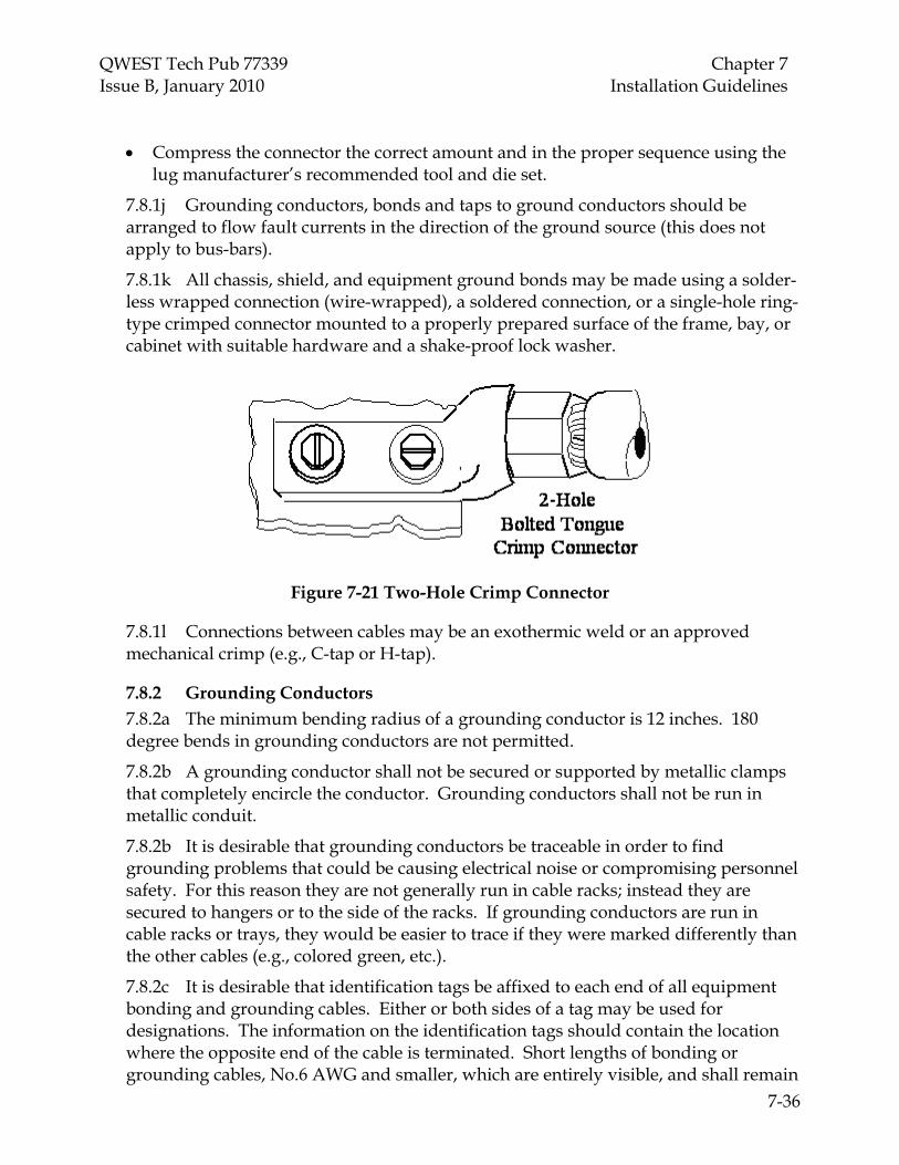
QWEST Tech Pub 77339 Chapter 7 Issue B, January 2010 Installation Guidelines
7-36
• Compress the connector the correct amount and in the proper sequence using the lug manufacturer’s recommended tool and die set.
7.8.1j Grounding conductors, bonds and taps to ground conductors should be arranged to flow fault currents in the direction of the ground source (this does not apply to bus-bars).
7.8.1k All chassis, shield, and equipment ground bonds may be made using a solder-less wrapped connection (wire-wrapped), a soldered connection, or a single-hole ring-type crimped connector mounted to a properly prepared surface of the frame, bay, or cabinet with suitable hardware and a shake-proof lock washer.
Figure 7-21 Two-Hole Crimp Connector
7.8.1l Connections between cables may be an exothermic weld or an approved mechanical crimp (e.g., C-tap or H-tap).
7.8.2 Grounding Conductors 7.8.2a The minimum bending radius of a grounding conductor is 12 inches. 180 degree bends in grounding conductors are not permitted.
7.8.2b A grounding conductor shall not be secured or supported by metallic clamps that completely encircle the conductor. Grounding conductors shall not be run in metallic conduit.
7.8.2b It is desirable that grounding conductors be traceable in order to find grounding problems that could be causing electrical noise or compromising personnel safety. For this reason they are not generally run in cable racks; instead they are secured to hangers or to the side of the racks. If grounding conductors are run in cable racks or trays, they would be easier to trace if they were marked differently than the other cables (e.g., colored green, etc.).
7.8.2c It is desirable that identification tags be affixed to each end of all equipment bonding and grounding cables. Either or both sides of a tag may be used for designations. The information on the identification tags should contain the location where the opposite end of the cable is terminated. Short lengths of bonding or grounding cables, No.6 AWG and smaller, which are entirely visible, and shall remain

QWEST Tech Pub 77339 Chapter 7 Issue B, January 2010 Installation Guidelines
7-37
so for their entire expected life, are exempted from this rule and are not required to be designated.
7.8.2d It is desirable to place “Do Not Disconnect” tags on all removable grounding electrodes and all terminating locations of main ground reference conductors.
7.8.3 Isolated and Integrated Grounding Considerations
7.8.3a In most Customer Premises installations, all of the grounding is considered “Integrated.” In some rare cases, installations will have switching equipment that requires an Isolated Grounding System. In these cases, the Isolated and Integrated ground planes must be properly designed, installed and maintained to provide adequate protection of personnel, equipment and service in accordance with the National Electrical Code (NEC).
7.8.3b When other telecommunications equipment (owned by the customer or other companies), or other metallic objects in a room will be placed within 6 feet of the Qwest equipment, they should also be ultimately grounded to the same ground source (e.g., bar) that Qwest is using. This will avoid potential differences between equipment that can be hazardous to personnel and/or damage equipment. This is the responsibility of the customer.
7.8.3c All bars that constitute the ground window shall be designated “GROUND WINDOW” once, adjacent to the bars and visible from the floor. The individual bars shall be designated for “ISOLATED” and “INTEGRATED” areas and each separate bar designated with its appropriate title (i.e., Main Ground Bus (MGB), Single Point Ground (SPG), etc).
7.8.3d Designate deliberate bond points made through surface contact with “GRD” in 3/8 inch or 36 point font. Designations shall be placed so that they are visible from the floor.
7.9 Hazardous Material Handling
Hazardous materials are those materials that are potentially hazardous to human health and the environment. The handling, packaging, storage, transportation and disposal of these materials are governed and regulated by various federal, state, and local laws that are very specific and restrictive on the handling of such materials. Violations can lead to fines and/or imprisonment for employees, Service Suppliers, and subcontractors for the illegal disposition of a regulated material.
The Service Supplier shall comply with Local, State, and Federal Regulations involving hazardous waste and/or materials. On jobs requiring dismantling of equipment or removal of equipment containing hazardous materials, the Service Supplier shall contact the Qwest representative before starting any removal work. The U S Environmental Protection Agency (EPA) has published regulations pertaining to the management and disposal of hazardous waste materials in compliance with the Resource Conservation and Recovery Act (RCRA).

QWEST Tech Pub 77339 Chapter 7 Issue B, January 2010 Installation Guidelines
7-38
In Customer Premises telecommunications locations, the following hazardous materials might be found:
• Relays using Mercury (Hg)
• Circuit Packs with components containing Mercury (Hg)
• Ballasts and transformers containing PCBs
• Radioactive Tubes
• Asbestos Resistors
• Asbestos Floor Tiles
• Flooded and VRLA Lead-Acid Batteries (and possibly their intercell connectors and bolts) containing Lead (Pb) and Sulfuric acid (H2S04), and capable of producing Hydrogen Gas (H2) and Hydrogen Sulfide Gas (H2S)
• Cable and Sleeves containing Lead (Pb)
• Cleaning supplies which might contain Solvents and CFCs
• Paint with hazardous materials such as Lead (Pb), etc.
7.10 Installation Documentation
7.10.1 Commonly Used Installation/Removal Forms
The Service Supplier shall be responsible for the proper completion and distribution of, all applicable forms and documents. Qwest forms listed in this section shall be used, without any alteration, except where specifically noted in this and other sections.
The following forms and labels are commonly used in Installation and Removal:
Table 7-3: Common Installation/Removal Forms
Form Type Form Description Qwest Pre-Sale Site
Survey Qwest survey conducted prior to closing sale to most accurately determine total labor hours, environmental, power, grounding, and equipment needs.
Sold Account Package (SAP)
Combines all above information for overview of Request, Pricing, Labor.
Vendor Pre-Sale Site Survey
Vendor survey conducted prior to closing sale to most accurately determine environmental, power, grounding, and equipment needs.

QWEST Tech Pub 77339 Chapter 7 Issue B, January 2010 Installation Guidelines
7-39
Table 7-3: Common Installation/Removal Forms (Con’t.)
Form Type Form Description Qwest
Statement/Scope of Work (SOW)
Chronological division of work to be performed under a contract or subcontract in the completion of Qwest installation portion of the project. Note: Answers the question, “How are we going to do what has been agreed upon in the SAP”?
Vendor Statement/Scope of
Work (SOW)
Chronological division of work to be performed under a contract or subcontract in the completion of Vendor installation portion of the project.
Qwest General and Detailed Method of
Procedures
General and detailed plan for pre-cutover testing, cutover plan, and post cutover testing.
Job Completion or Extension Reporting
(Installation Checklist for Site
Acceptance)
Completed by Project Manager and customer to initiate billing to customer for sale. Includes all pertinent rest records and documentation.
Vendor Acceptance Initiates payment to Vendor for sale.
7.10.2 Job Packet and Job Log
The Service Supplier should use the RG 51-0083 Job Packet Envelope for all installation or removal activities where documentation and job papers are to be turned over to Qwest. Job Packets must be kept as turned over by the Service Supplier for a minimum of 180 days after job completion date. Job packet contents that have been stored longer than the final hold date shall be discarded by the PSAP representative after essential documentation has been removed and filed. The Service Supplier should complete all information required on the face of the envelope. It is not permissible for the Service Supplier to modify in any way.
The Job Packet may contain, but is not necessarily limited to:
• E-911 Closeout Documentation
• All Methods Of Procedure (MOPs) related to
• All Software discs and applications associated to the install
• Job Log
• Test Records
• Bills of Lading
• Drawings/Records (“installer marked” shall be identified)
QWEST Tech Pub 77339 Chapter 7 Issue B, January 2010 Installation Guidelines
7-40
• Material Inventory of Missing Items
• Service Interruption report if problem occurred
• A Job Log should be provided and will typically include, but not be limited to the following:
o Deviations from the Statement of Work (SOW), Specification or Standards approved by the Sales Engineer.
o Material shortages and impact on job progress.
o Engineering changes.
o Communications with Sales Engineers and other relevant parties. o Security or safety problems
Note: A copy of the Job Log should be included in the Job Packet.
7.10.3 Job Completion or Extension Reporting
The Service Supplier shall report the completion of a job on the Installation Checklist for Site Acceptance (Refer to Par. 7.12). Advanced or partial completion of the job shall also be reported on this form. One copy of this form shall be forwarded to the Sales Engineer for retention.
7.10.4 Service Interruption/Degradation Report
When a Service Interruption/Degradation Report (RG 47-0013) is required, the Service Supplier shall notify the Sales Engineer. A copy of the report shall be sent to the Regulatory Analysis and Interface Group, 700 West Mineral Ave., Room NEE29.22, Littleton, Colorado 80120 (FAX 303-707-2229) within 24 hours of the occurrence. Refer to Fig. 7-24 on p. 7-60.
7.10.5 Returning Material
When the Services Supplier needs to return excess CPE material to Qwest, the Service Supplier shall note the return quantity on the Installation Checklist for Site Acceptance form (material must be a complete unit). Refer to Fig. 7-22 on p. 7-51.
Contact the pack-and-hold service center as soon as possible.
For claims, the following documentation is required:
• Copy of the delivery receipt
• Copy of the packing slip
• Statement concerning the circumstances
• Other documentation may be required
QWEST Tech Pub 77339 Chapter 7 Issue B, January 2010 Installation Guidelines
7-41
Damages, overages, and shortage may require material return process. The Service Supplier will be directed by the pack-and-hold center to file a “vendor claim” for overage, shortage or damaged material. To file a claim for common system material that is incorrect upon receipt of shipment, complete the “Report of Unsatisfactory Shipment” on the back of the packing slip.
A Service Supplier shall not scrap material without approval from the Sales Engineer, or instructions in the SOW. Once authorization has been obtained, locate the Material Reclamation Center for your area, and call (877-879-7447) to make transportation arrangements.
7.11 Installation Methods of Procedure (MOPs)
This section describes the minimum requirements for the preparation of a Method Of Procedure (MOP) required for all work operations performed on equipment being added, removed or modified in any manner, in PSAP equipment facilities. The MOP is a written document which details General or Detailed procedures and operations which shall be followed in their entirety.
The Service Supplier shall be responsible for the writing of the MOP before the start of any installation activity. Where possible, a Qwest Sales Engineer should review and concur in its content. That individual may or may not have specific work-related activities detailed on the MOP. Responsibility for work functions and operations are indicated on the MOP through a check off system. While Qwest personnel signatures are normally required on MOPs for Central Office installation activity, it is recognized that this will not always be possible in Customer Premises installations. However, even though it is not an absolute requirement, the Service Supplier should make an effort to meet with a Qwest Sales Engineer, and have them review the MOP, and sign off on it. Whether Qwest signatures are obtained or not, a MOP shall be posted for all installation activities.
The Service Supplier Representative responsible for the preparation of the MOP should be knowledgeable in the proper use and completion of the MOP form and in the case of Detail MOPs, should be experienced in the specific work operations involved and familiar with Qwest standards.
The Service Supplier shall send a copy of the General or Detailed MOP to the Sales Engineer. Note: Refer to RG 47-0163
A properly written MOP is intended to prevent the occurrence of costly service interruptions and to assure that work is performed in a safe and secure manner. It is the responsibility of the supplier preparing the MOP to clearly and accurately represent all work to be performed and to detail all required steps, procedures and locations where work is to be performed. Every effort shall be made by the Service Supplier and Qwest Sales Engineer to work cooperatively to assure that no degradation of equipment or service will occur.

QWEST Tech Pub 77339 Chapter 7 Issue B, January 2010 Installation Guidelines
7-42
All completed MOP forms shall be retained by the Service Supplier at the site where the work operation will take place. During the installation process, a copy of the MOP shall be posted in a convenient location, preferably near the actual equipment being installed, modified, or removed. Completed MOP forms shall be included with job documentation.
It shall be understood by all parties that the content of individual MOPs shall be used to help assign responsibility for work operations, procedural errors, service outages and accidents that may occur during the exercise of the detailed procedures. It is in the interest of all involved parties to assure that each MOP is complete and accurate.
The MOP form may be used to combine both the General and Detail process where the job complexity is such that separate forms are not justified. However, this does not allow for the short cutting of any of the required information as detailed in this section. When the MOP is intended to serve as a combined MOP, both the General and Detail boxes shall be checked.
7.11.1 General MOPs
A General MOP, written to install, remove or modify equipment, shall be prepared for each BVAPP order number and location. This also includes such activities as software loads, Product Change Notices (PCNs) and AC or DC power activities.
The Work Description section of a General MOP defines, in broad terms, the activity to be performed as well as the amount and type of equipment involved. Extended breaks (greater than 30 days) in installation activity require cleanup and abandonment of the area and a new authorized General MOP upon restart of the activity.
7.11.2 Detailed MOPs
A separate Detail MOP shall be required for all work to be performed on live equipment, whether presently in service or not. This includes any work on equipment that is in an area where potential hazards to equipment or personnel exist. The work description section of a Detail MOP defines each step of the process and, in effect, is the step-by-step procedure under which the activity shall be performed.
This includes all precautionary steps before, during and after each work effort. For service-affecting work, the MOP should also include back-out procedures. Success of the particular activity depends highly on the accuracy and completeness of this form.
Any document referenced in the step-by-step procedure, should be on site and readily available for use.
All Detailed MOPs must be approved by the Qwest 911 CPE Technical Support Group Before implementation of the work to be performed.
7.11.3 MOP Header Fields
The MOP header provides spaces for the following information which shall be completed without exception:
• City in which the work will be performed.

QWEST Tech Pub 77339 Chapter 7 Issue B, January 2010 Installation Guidelines
7-43
• State in which the work will be performed. This field may use commonly accepted state abbreviations.
• Office in which the work will be performed. If the office is the only one in that city, the term MAIN may be used; otherwise, use the proper name for the office such as; 8th Street, Garden Park, etc.
• Phone number for the office in which the work is to be performed. Where possible, this phone line shall appear and be available in the equipment room where the work operation will take place.
• Start Date shall indicate the actual date on which the work activity is to begin. This information may be in the MM/DD/YY format.
• Start Time shall indicate the point at which the work activities defined under WORK DESCRIPTION DETAILS may begin. Only those activities defined as preparation, such as tool preparation, site protection, site and equipment tagging or marking and information resource consolidation, may occur prior to this time. The actual Start Time entry shall take careful consideration of such factors as high/low traffic periods and circuit application and shall be determined by the Local Network Operations Supervisor. General MOP shall indicate the normal work shift start time.
• Completion Date shall indicate the actual date on which the work activity will conclude. This information may be in the MM/DD/YY format.
• Completion Time shall indicate the point at which all activity defined under WORK DESCRIPTION DETAILS must stop. Sufficient time shall be provided in the MOP planning stage so as not to place the Completion Time in jeopardy. No further work will be allowed after the Completion Time except for such non-service effecting activities as records correction and site cleanup. General MOP shall indicate the normal shift complete time.
• Order Number shall be the order number as it appears on the equipment order.
• Supplier Order Number shall be entered if the Service Supplier has a unique number, in addition to the order number, associated with either the detail specification or the installation process itself.
• System Type shall reflect only the equipment involved in this MOP such as E-911, POWER, etc.
The header information provides a location to indicate individual page numbers as well as the total pages in the entire MOP. A statement below the header information includes the authorization to duplicate this blank form when additional entry space is required. An expansion sheet (RG 47-0006) is also available if desired. In either case, multiple sheets of either type shall be consecutively numbered as appropriate, (i.e., 1 of 3, 2 of 3 and 3 of 3).

QWEST Tech Pub 77339 Chapter 7 Issue B, January 2010 Installation Guidelines
7-44
7.11.4 MOP Work Description Details
The purpose of this section is to define, in specific terms, the generic equipment types and work activity covered under a General MOP or to provide specific step-by-step procedures to be followed for a Detail MOP. The header information on the form indicates the intended application of the MOP.
The Service Supplier shall collect all essential information available for the job and confer (where possible) with the Qwest Sales Engineer regarding the proposed sequence of work operations. An initial MOP walk-through, if needed or requested, shall be conducted at the work site, to identify potential hazards and special conditions that may effect work operations. Those items shall include such considerations as building and equipment conditions, customer service, safety issues, corrective measures and security procedures.
The work description portion of a Detail MOP shall be completed by the Service Supplier who will be responsible for the work operation. The Service Supplier representative shall be familiar with MOP procedures, and Qwest E-911 installation workmanship requirements as defined in various applicable publications; and be qualified to perform the work operations detailed within the MOP, regardless of whether they will actually perform each step of the procedure themselves.
A Service Supplier’s qualifications for involvement in the MOP writing process and work procedures shall be the responsibility of the Service Supplier. Each Supplier shall accept the responsibility for the work performed by their employees and their subcontractors.
The work description portion of a General MOP may be prepared by a representative of the Service Supplier provided that person is familiar with the generic equipment type and activity represented in the job detail specification.
All work detailed in the MOP shall conform to standards specified in this Tech Pub, and other publications referenced herein.
The work description in the MOP shall include all steps necessary to perform the work. Each step shall be numbered in the space provided and appear in the order in which they will occur in the work operation.
The Work Description Details portion of the MOP shall contain narrative references to all applicable steps. The check list entitled “Have You Considered” is intended purely to enhance the completeness of the narrative write-up and may not be used to indicate the subjects’ application to this MOP. Some examples would be if tools need to be insulated, the narrative should say “All required tools have been properly insulated.” If fuses are to be involved a statement such as, “30-A fuses and spares are available for fuse panel 0101.01 and alarms have been tested”, etc.
Examples of write-up considerations are (note that this list is not all-inclusive):
• Equipment Added, including all frames, bays, units and apparatus
QWEST Tech Pub 77339 Chapter 7 Issue B, January 2010 Installation Guidelines
7-45
• Equipment Removed, including all frames, bays, units and apparatus tagged or identified
• Equipment Compatibility with existing units and circuits
• Affected Working Circuits not listed as added or removed on this work specification.
• Restricted Work Hours — to be listed in the MOP header information (Qwest requires that some potentially service-affecting activities be performed in the Maintenance Window [see Section 7.1.7]; and there are other opportune times for certain types of installation work, often depending on the particular loads and needs of that site)
• Work Area Protection to adjacent equipment and building
• Special Tools/Materials, such as circuit pack pullers, hoists, ungrounded drills, HEPA vacuum, etc.
• Tool Insulation, including taping and inspection of all insulated tools
• Safety Considerations, including goggles, floor clutter, rubber gloves and aprons, insulated power blankets, etc.
• Emergency Equipment and Procedures Available, including first aid, hazardous material, fire, etc.
• Procedures Available that are manufacturer or product specific
• Fuse Alarm Operation checked for added and affected circuits
• Location of Spare Fuses — has been checked for availability
• Records Correction where existing information has been altered
• Hazardous Material Handling and Storage policies, labeling, storage supplies and required paperwork available
• Personnel Experience considered for both work effort and MOP responsibility • Before and After Tests — to be performed on applicable circuits
• Backout Procedures — covered in the eventuality that hardware, software errors or time restrictions preclude service restoration by the designated COMPLETION TIME
• Referenced Documents should be on site and readily available for use
• Technical References are available and understood
• Required Qwest Support has been discussed and is available (if necessary)
• Emergency Restoration Plans have been discussed and are in place for any eventuality

QWEST Tech Pub 77339 Chapter 7 Issue B, January 2010 Installation Guidelines
7-46
• Fuses and Leads Tagged for identification purposes, including any AC circuits under LOCKOUT condition
• Office Records/Drawings Available on site when necessary
• Supplier Drawings Available on site when necessary, as well as installation instructions and manuals
• MOP Referenced Documents — on site and available for use
For each numbered procedure or step listed, a check off box has been included to indicate whether the step is the responsibility of the Local Network Operations Technician providing coverage or the responsibility of the Service Supplier (in the case of Customer Premises installations, it is usually going to be the responsibility of the Service Supplier).
7.11.5 MOP Write-Up Review
Following the preliminary MOP write-up, the Service Supplier Personnel who will be performing the work operations and, if possible, the Local Network Operations Personnel who will be responsible for coverage, should conduct a dry run of the detailed procedures. At this time, any shortcomings or omissions in the write-up shall be addressed.
7.11.6 MOP Approval/Signing Authorities
On a General MOP, the Service Supplier Representative may be the person performing the actual work activity. This person may be a Service Supplier’s supervisor or any duly appointed personnel. All signing parties shall fill in their proper title, daytime phone number and date of signature in the appropriate field.
7.11.7 Service Interruptions
If a service interruption occurs during installation or removal activity, service must be restored quickly. The Service Supplier personnel and the Qwest Representatives shall work cooperatively to ensure that actual outage time is kept to a minimum.
The Qwest E-911 Operations/SRC (1-800-357-0911) shall be called immediately and informed of the outage and of the actual or expected term of the outage. Refer also to Par. 7.10.

QWEST Tech Pub 77339 Chapter 7 Issue B, January 2010 Installation Guidelines
7-47
7.12 Installation Checklist for Site Acceptance
The INSTALLATION CHECKLIST FOR SITE ACCEPTANCE (Figure 7-22 on p. 7-48) is the most commonly used PSAP Customer Premises installation form for conducting a site acceptance (and is included on the following pages). Some of the additional forms that could be adapted (based on the practices described in this Tech Pub) can also be found in Tech Pub 77350.
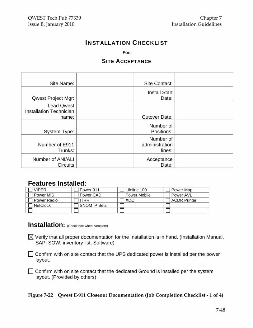
QWEST Tech Pub 77339 Chapter 7 Issue B, January 2010 Installation Guidelines
7-48
INSTALLATION CHECKLIST FOR
SITE ACCEPTANCE
Site Name: Site Contact:
Qwest Project Mgr: Install Start
Date:
Lead Qwest Installation Technician
name: Cutover Date:
System Type: Number of Positions:
Number of E911 Trunks:
Number of administration
lines:
Number of ANI/ALI Circuits
Acceptance Date:
Features Installed:
VIPER Power 911 Lifeline 100 Power Map Power MIS Power CAD Power Mobile Power AVL Power Radio ITRR XDC ACDR Printer NetClock SNOM IP Sets
Installation: (Check box when complete)
Verify that all proper documentation for the Installation is in hand. (Installation Manual, SAP, SOW, inventory list, Software)
Confirm with on site contact that the UPS dedicated power is installed per the power layout.
Confirm with on site contact that the dedicated Ground is installed per the system layout. (Provided by others)
Figure 7-22 Qwest E-911 Closeout Documentation (Job Completion Checklist - 1 of 4)

QWEST Tech Pub 77339 Chapter 7 Issue B, January 2010 Installation Guidelines
7-49
Validate that all racking equipment is installed and ready (Racks, power strips, ladder racking, plywood, 110 blocks, patch panels etc.)
Label all hardware equipment within the racks and cabinets.
Label all Physical layer cable and jacks.
Label all patch cables between the cabinet and rack.
Servers installed on a secure shelf with dedicated power
Printers installed on a secure surface
Positron Cabinet in a secure environment
Identify the Network circuit locations, tag or label.
ALI/ANI Circuits, How Many E911 Circuits, How Many Administration Lines, How Many Ring down Circuits, How Many One RAS circuit for Dial up modem located on the shelf in the rack. Installation Guidelines:
As the equipment is installed you must dress the primary network cables, power cords, Patch Cords in the back and front of the racks for final placement, they must be neat and clean appearance.
As the new patch cords for data connections are installed dress them for final
placement, they must be neat and clean appearance.
All equipment power must be plugged into the rack mounted power strips
Power strip cords should be dressed across bottom of ladder racking to reach outlets. Once reaching the wall, tie wraps should be used to dress them down the wall as needed. Plug the power strip cords into the outlets designated for the UPS power.
Pre testing (Prior to Cut)
ALI/ANI Tested E911 Circuits Tested Administration Lines Tested Ring down Circuits Tested
Figure 7-22 Qwest E-911 Closeout Documentation (Job Completion Checklist - 2 of 4)
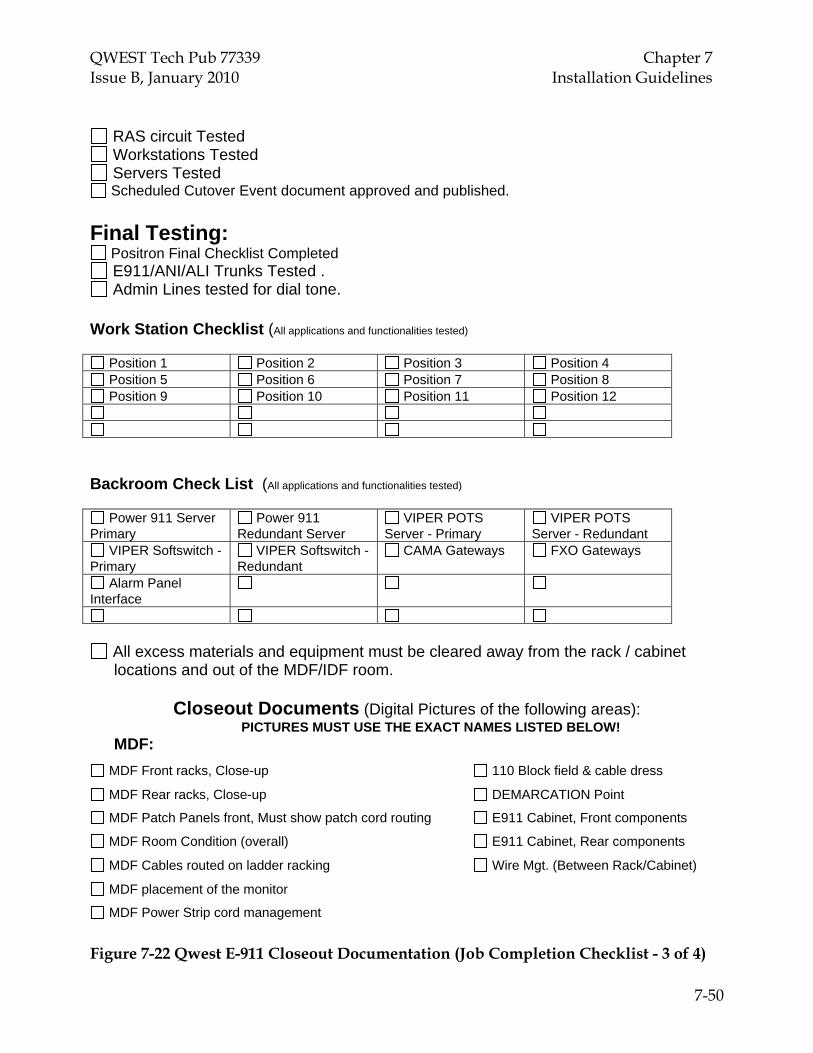
QWEST Tech Pub 77339 Chapter 7 Issue B, January 2010 Installation Guidelines
7-50
RAS circuit Tested Workstations Tested Servers Tested Scheduled Cutover Event document approved and published.
Final Testing:
Positron Final Checklist Completed E911/ANI/ALI Trunks Tested . Admin Lines tested for dial tone.
Work Station Checklist (All applications and functionalities tested)
Position 1 Position 2 Position 3 Position 4 Position 5 Position 6 Position 7 Position 8 Position 9 Position 10 Position 11 Position 12
Backroom Check List (All applications and functionalities tested)
Power 911 Server Primary
Power 911 Redundant Server
VIPER POTS Server - Primary
VIPER POTS Server - Redundant
VIPER Softswitch - Primary
VIPER Softswitch - Redundant
CAMA Gateways FXO Gateways
Alarm Panel Interface
All excess materials and equipment must be cleared away from the rack / cabinet locations and out of the MDF/IDF room.
Closeout Documents (Digital Pictures of the following areas):
PICTURES MUST USE THE EXACT NAMES LISTED BELOW! MDF:
MDF Front racks, Close-up 110 Block field & cable dress
MDF Rear racks, Close-up DEMARCATION Point
MDF Patch Panels front, Must show patch cord routing E911 Cabinet, Front components
MDF Room Condition (overall) E911 Cabinet, Rear components
MDF Cables routed on ladder racking Wire Mgt. (Between Rack/Cabinet)
MDF placement of the monitor
MDF Power Strip cord management
Figure 7-22 Qwest E-911 Closeout Documentation (Job Completion Checklist - 3 of 4)

QWEST Tech Pub 77339 Chapter 7 Issue B, January 2010 Installation Guidelines
7-51
Excess Material Returned to Qwest for Re-Use:
Outstanding Issues:
Notes:
Qwest wants to be sure the system is working appropriately and that we have addressed all design and operational issues within 30 days of cutover. Please acknowledge any issues or grant acceptance for the site.
PSAP Manager Printed: ________________________
PSAP Manager Signature: _____________________
Date: ___________________________________________
Qwest Representative Printed: ___________________
Qwest Representative Signature: ___________________
Date: ___________________________________________
DISTRIBUTE DOCUMENT TO THE QWEST PROJECT TEAM VIA EMAIL
Figure 7-22 Qwest E-911 Closeout Documentation (Job Completion Checklist - 4 of 4)

QWEST Tech Pub 77339 Chapter 7 Issue B, January 2010 Installation Guidelines
7-52
Figure 7-23 RG 47-0163 Method of Procedure E-911 PSAP Installation/ Removal/ Modification/ New (Page 1 of 8)

QWEST Tech Pub 77339 Chapter 7 Issue B, January 2010 Installation Guidelines
7-53
Figure 7-23 RG 47-0163 Method of Procedure E-911 PSAP Installation/ Removal/ Modification/ New (Page 2 of 8)

QWEST Tech Pub 77339 Chapter 7 Issue B, January 2010 Installation Guidelines
7-54
Figure 7-23 RG 47-0163 Method of Procedure E-911 PSAP Installation/ Removal/ Modification/ New (Page 3 of 8)

QWEST Tech Pub 77339 Chapter 7 Issue B, January 2010 Installation Guidelines
7-55
Figure 7-23 RG 47-0163 Method of Procedure E-911 PSAP Installation/ Removal/ Modification/ New (Page 4 of 8)

QWEST Tech Pub 77339 Chapter 7 Issue B, January 2010 Installation Guidelines
7-56
Figure 7-23 RG 47-0163 Method of Procedure E-911 PSAP Installation/ Removal/ Modification/ New (Page 5 of 8)

QWEST Tech Pub 77339 Chapter 7 Issue B, January 2010 Installation Guidelines
7-57
Figure 7-23 RG 47-0163 Method of Procedure E-911 PSAP Installation/ Removal/ Modification/ New (Page 6 of 8)

QWEST Tech Pub 77339 Chapter 7 Issue B, January 2010 Installation Guidelines
7-58
Figure 7-23 RG 47-0163 Method of Procedure E-911 PSAP Installation/ Removal/ Modification/ New (Page 7 of 8)

QWEST Tech Pub 77339 Chapter 7 Issue B, January 2010 Installation Guidelines
7-59
Figure 7-23 RG 47-0163 Method of Procedure E-911 PSAP Installation/ Removal/ Modification/ New (Page 8 of 8)

QWEST Tech Pub 77339 Chapter 7 Issue B, January 2010 Installation Guidelines
7-60
RG 47-0013
Service Interruption / Service Degradation Report To: Location: Office City State BVAPP
Time & Date Reported Time & Date Cleared
Type of Equipment MOP Completed/Approved? ____Yes ____No
Description of Service Interruption: Corrective Action Taken: Service Supplier Company Name Telephone #
Service Supplier Rep Signature: Date:
Figure 7-24 RG 47-0113 Service Interruption / Service Degradation Report

QWEST Tech Pub 77339 Chapter 8 Issue B, January 2010 References
TOC 8-i
CONTENTS
Chapter and Section Page
8. References ...................................................................................................................... 8-1 8.1 Acronyms and Definitions............................................................................... 8-1 8.2 Qwest Technical Publications ......................................................................... 8-4 8.3 Telcordia Documents........................................................................................ 8-4 8.4 Other Documents .............................................................................................. 8-5 8.5 Ordering Information....................................................................................... 8-6 8.6 Trademarks ........................................................................................................ 8-9

QWEST Tech Pub 77339 Chapter 8 Issue B, January 2010 References
8-1
8. References
8.1 Acronyms and Definitions
A Amp/Ampere/Amperes (a measure of electric current) AC Alternating Current (electricity from the power utility; typically available at
120/240 V, single-phase, or 120/208 V, three-phase in a Customer Premises location)
ACEG AC Equipment Ground (commonly known as the “green-wire” ground run with most AC circuits)
ANSI American National Standards Institute atm atmospheres (measure of pressure — 1 atmosphere is the air pressure at sea
level) AWG American Wire Gauge (wire size standard) BDFB Battery Distribution Fuse Board/Bay BEGS Building Earth Grounding System BICS Building Industry Consultant Services (guidelines for termination of
telecommunications services on a Customer’s Premises) BSS Building Structural Steel BTU British Thermal Units (a measure of heat energy) C Celsius or Centigrade (temperature) cc cubic centimeter, equal to 1 millimeter (ml) CAMA Centralized Automatic Message Accounting CEGB Cable Entrance Ground Bar CEF Common Entrance Facility CFC Chloro-Fluoro Carbon (an ozone destroying chemical used as a propellant or
coolant) cfm cubic feet per minute CLLI™ Common Language Location Identifier (Telcordia Trademark) cm centimeter CN Change Notice (initiated by an equipment supplier to make changes to their
equipment — may be the same as a PCN where CN is a specific term used by the suppliers, and PCN is the generic term used by Qwest and Telcordia)
CO Central Office CO2 Carbon Dioxide CPE Customer Premise Equipment (common catch-all for equipment such as
telephones, modems, etc., usually owned by the customer, which connect to the Qwest [or other telecomm carriers'] Network).
CPR Cardio-Pulmonary Resuscitation

QWEST Tech Pub 77339 Chapter 8 Issue B, January 2010 References
8-2
CPU Central Processing Unit CSA Canadian Standards Association CWP Cold Water Pipe DC Direct Current (electricity normally used by telecommunications equipment;
rectified from AC, typically to -48 V) dBrnC decibels referenced to Noise Level C (an audible noise measurement of the
AC ripple component of a DC voltage or current) DEMARC Point of Demarcation E-911 Enhanced 911 Service EHS Environmental, Health, and Safety (an internal Qwest group) EIA Electronics Industry Association EMT Electrical Metallic Tubing (a type of conduit used for AC circuits) EPA Environmental Protection Agency EQL Equipment Location ESD Electro-Static Discharge (discharge of accumulated static electricity from the
human body) F Fahrenheit FCC Federal Communications Commission FPS Fiber Protection System ft foot GFCI Ground Fault Circuit Interruptor GMT a 0-20 Amp small fuse type used for power and alarming HazMat Hazardous Material (as defined by the EPA) HEPA High Efficiency Particulate Arrestor (specially rated filters and devices that
remove most of the dust and particulates from the air) hr hour HSP House Service Panel (at the commercial AC service entrance to a building) HVAC Heating, Ventilation and Air-Conditioning IEEE Institute of Electrical and Electronics Engineers IDF Intermediate Distributing Frame IFCI International Fire Code Institute IGP Isolated Grounding Plane in inches IP Internet Protocol kbps kilobits per second (digital transmission frequency/speed) kHz a measure of thousands of sound waves per second kPa kilo-Pascals (standard measurement of pressure) kVA kilo-Volt-Amperes (a measure of total electrical power used or provided)

QWEST Tech Pub 77339 Chapter 8 Issue B, January 2010 References
8-3
kW kiloWatts (thousands of Watts) L Liters (sometimes abbreviated with a cursive l) lbs pounds LNO Local Network Operations (Qwest Communications’ internal Outside Plant
field Operations forces) LVR Logging Voice Recorder m meter Mbps Megabits per second (one Megabit = 1000 kilobits) MDF Main Distributing Frame min minute ml milliliter MOP Method of Procedure (a detailed plan for installation/removal work) MGN Multi-Ground Neutral NEBS Network Equipment — Building System (see the Telcordia references in
Section 11.3 of this document) NEC National Electrical Code NEMA National Electrical Manufacturers’ Association NFPA National Fire Protection Association NI Network Interface (the point of demarcation between Qwest equipment, and
the copper or fiber plant owned by the customer) Ni-Cad or NiCd Nickel-Cadmium battery OPGP Office Principle Grounding Point OSHA Occupational Safety and Health Administration (Division of U.S. Dept. of
Labor) Ø Phase (the Greek letter Phi, denoting the number of electrical phases of
power, which directly correlates to the number of wires) Ω Ohms (the Greek letter Omega, signifying the impedance or resistance in an
electrical circuit) P Power (measured in Watts) PB or PBD Power Board (the main DC plant distribution bays/panels) PBX Private Branch Exchange (a small switch owned by customers) PCN Product Change Notice PDB Power Distribution Bay PID Product IDentification number psf pounds per square foot PSAP Public Service Access Point psi pounds per square inch Pub abbreviation of Publication (as in Qwest Technical Publication)

QWEST Tech Pub 77339 Chapter 8 Issue B, January 2010 References
8-4
PVC Poly-Vinyl Chloride (a plastic tubing pipe commonly used as water pipe) s or sec second RR Relay Rack SAP SLPP Safety and Loss Prevention Program (a manual of environmental health and
safety practices produced by the Qwest EHS group) SOW Statement of Work SPGS Single Point Grounding System UL Underwriters’ Laboratories UPS Uninterruptible Power Supply (a commercially available assembly of
rectifiers, batteries and inverters — or in rare cases a motor-generator set and a flywheel — which ensures that clean AC power is available, and on loss of commercial AC, usually provides 15-30 minutes of backup — it is available in various kVA sizes)
V Volts or Volume VAC AC rms Voltage (a measure of the strength of the electrical “pressure”) VDC DC Voltage VoIP Voice Over Internet Protocol VRLA Valve-Regulated Lead-Acid (a type of battery commonly used in the OSP) W Watts (a measure of “real” electrical power used or produced) WFCA Western Fire Chiefs Association
8.2 Qwest Technical Publications
Pub 77350 Telecommunications Equipment Installation and Removal Guidelines, Issue N, January 2007
Pub 77351 Engineering Standards General Equipment Requirements, Issue F, June 2001
Pub 77355 Grounding - Central Office and Remote Equipment Environment, Issue G, June 2006
Pub 77368 Commercial Customer Premises Electronic Equipment Environmental Specifications and Installation Guide, Issue F, March 2007
Pub 77385 Power Equipment and Engineering Standards, Issue I, January 2007 SLPP Safety and Loss Prevention Program, December 2004 Issue
8.3 Telcordia Documents
BR-101-170-005 Quality and Reliability — Electrostatic Discharge, Issue 3, June 1996 BR 760-550-102 Building Ventilation, Issue 3, October 1981 BR 781-810-885 Central Office Ventilation, Issue 1, August 1987

QWEST Tech Pub 77339 Chapter 8 Issue B, January 2010 References
8-5
BR 790-100-672 Battery Maintenance Practices for Flooded and Valve Regulated Acid Batteries, Issue 1, December 1993
GR-26-CORE Generic Requirements for CEVs, Issue 1, December 1994 GR-27-CORE Generic Requirements for Environmental Control Systems for EEEs,
Issue 1, November 1994 GR-63-CORE Network Equipment — Building System (NEBS) Requirements:
Physical Protection, Issue 3, December 2005 GR-295-CORE Isolated and Mesh Bonding Networks: Definition and
Application to Telephone Central Offices, Issue 1, November 2004 GR-409-CORE Generic Requirements for Premises Fiber Optic Cable, Issue 1, June
1994 GR-833-CORE Operations Application Messages — Network Maintenance:
Network Element and Transport Surveillance Messages, Issue 6, December 2006
8.4 Other Documents
ANSI/TIA/EIA 607 BICSI Commercial Building Telecommunications Grounding Standard, 2001 Edition
ANSI T1.329 Network Equipment Earthquake Resistance, 2002 Issue ASHRAE Std. 62.1 Ventilation for Acceptable Indoor Air Quality, 2004 Issue ATIS PP-0600003 Battery Enclosure and Rooms/Areas, 2007 Issue C&D 41-6739 Gassing and Ventilation, October 1995 Issue C&D 41-7329 Life Expectancy and Temperature, June 1999 Issue EIA/TIA 568-B.3 Optical Fiber Cabling Components Standard, 2000 Issue Enersys Section 58.00 Safety, Storage, Installation, Operation, and Maintenance Manual
for Heritage Series Flooded Lead Acid Battery Systems, 2000 Issue IBC International Building Code, published by the International Code
Council (ICC), 2006 Edition IFC International Fire Code, published by the International Code
Council (ICC) and the International Fire Code Institute (IFCI), 2006 Edition
IEEE/ASHRAE 1635 Guide for Ventilation and Thermal Management of Stationary Battery Installations, 2007 Edition
IEEE Std 450 IEEE Recommended Practice for Maintenance, Testing, and Replacement of Vented Lead-Acid Batteries for Stationary Applications, 2002 Edition
IEEE Std 484 IEEE Recommended Practice for Installation Design and Installation of Vented Lead-Acid Batteries for Stationary Applications, 2004 Edition

QWEST Tech Pub 77339 Chapter 8 Issue B, January 2010 References
8-6
IEEE Std 485 IEEE Recommended Practice for Sizing Large Lead Storage Batteries for Generating Stations and Substations, 2004 Edition
IEEE Std 1184 IEEE Guide for the Selection and Sizing of Batteries for Uninterruptible Power Systems, 2006 Edition
IEEE Std 1187 IEEE Recommended Practice for the Design and Installation of Valve-Regulated Lead-Acid Storage Batteries for Stationary Applications, 2003 Edition
IEEE Std 1188 IEEE Recommended Practice for Maintenance, Testing, and Replacement of Valve-Regulated Lead-Acid Batteries for Stationary Applications, 2005 Edition
IEEE Std 1189 IEEE Guide for the Selection of Valve-Regulated Lead-Acid (VRLA) Batteries for Stationary Applications, 2006 Edition
IEEE 1578 IEEE Recommended Practice for Battery Electrolyte Spill Containment and Management, 2006 Edition
NFPA 1 Uniform Fire Code, 2006 Edition NFPA 37 Standard for the Installation and Use of Stationary Combustion
Engines and Gas Turbines, 2002 Edition NFPA 70 National Electrical Code (NEC), 2005 Edition NFPA 70HB NEC Handbook, 2005 Editon NFPA 110 Standard for Emergency and Standby Power Systems, 2005 Edition NFPA 111 Standard on Stored Electrical Energy Emergency and Standby
Power Systems, 2005 Edition OSHA 29 CFR Standard 1926.417, Lockout and Tagging of Circuits Uniform Building Code (UBC) Vols. 1-3, published by the International Conference of
Building Officials (ICBO), 1997 Edition Uniform Fire Code Vols. 1-2, published by the Western Fire Chiefs Association
(WFCA), 1997 Edition UL 60950 Safety of Information Technology Equipment, Including Electrical
Business Equipment, 3rd Edition, 2000 (replaced UL 1950) 8.5 Ordering Information
All documents are subject to change and their citation in this document reflects the most current information available at the time of printing. Readers are advised to check status and availability of all documents.
Those who are not QWEST employees may order;

QWEST Tech Pub 77339 Chapter 8 Issue B, January 2010 References
8-7
American National Standards Institute (ANSI) documents from:
American National Standards Institute 11 West 42nd Street New York, NY 10036 Phone: (212) 642-4900 Fax: (212) 302-1286
Web: www.ansi.org
ANSI has a catalog available which describes their publications.
ASHRAE Documents may be obtained from:
American Society of Heating, Refrigeration and Air-Conditioning Engineers, Inc. 1791 Tullie Cir. NE Atlanta, GA 30329 Fax: (404) 321-5478 Phone: (800) 527-4723 Web: www.ashrae.org
ATIS Documents may be obtained from:
Alliance for Telecommunications Industry Solutions 1200 G St. NW Washington D.C. 20005 Fax: (202) 393-5453 Phone: (202) 628-6380 Web: www.atis.org
C&D Dynasty Documents may be obtained from:
C&D Technologies Dynasty Division 900 E. Keefe Ave. Milwaukee, WI 53212 Fax: (414) 961-6506 Phone: (800) 396-2789 Web: www.dynastybattery.com

QWEST Tech Pub 77339 Chapter 8 Issue B, January 2010 References
8-8
Enersys Documents may be obtained from:
Enersys Inc. 2366 Bernville Rd. Reading, PA 19605 Fax: (610) 372-8457 Phone: (610) 208-1991 Web: www.enersysreservepower.com/products.asp
Federal Regulations may be obtained from:
Web: www.access.gpo.gov/nara/cfr/index.html
International and Uniform Building and Fire Codes may be obtained from:
International Code Council 5203 Leesburg Pike, Ste. 600 Falls Church, VA 22041 Fax: (703) 379-1546 Phone: (703) 931-4533 Web: www.intlcode.org
IEEE Documents may be obtained from:
Institute of Electrical and Electronics Engineers, Inc. 345 East 47th Street New York, NY 10017-2394 Fax: (732) 981-1721 Phone: (732) 981-0060 Web: www.ieee.org
NFPA Documents may be obtained from:
National Fire Protection Association 1 BatteryMarch Park Quincy, MA 02269-9101 Fax: (617) 770-0700 Phone: (617) 770-3000 Web: www.nfpa.org
QWEST Technical Publications may be obtained from:
Web: www.qwest.com/techpub

QWEST Tech Pub 77339 Chapter 8 Issue B, January 2010 References
8-9
Telcordia documents may be obtained from:
Telcordia Customer Relations 8 Corporate Place, PYA 3A-184 Piscataway, NJ 08854-4156 Fax: (908) 336-2559 Phone: (800) 521-CORE (2673) (U.S. and Canada) Web: www.telcordia.com
TIA Documents may be obtained from:
Telecommunications Industry Association 2500 Wilson Blvd., Ste. 300 Arlington, VA 22201 Fax: (703) 907-7727 Phone: (703) 907-7700 Web: www.tiaonline.org
UL Documents may be obtained from:
Underwriters Laboratories 333 Pfingsten Rd. Northbrook, IL 60062-2096 Fax: (847) 272-8129 Phone: (847) 272-8800 Web: www.ul.com
Employees of QWEST may order paper copies of publications by submitting form RG 31-0033 to:
Central Distribution Center (CDC) 1005 17th St., S-30 Denver, CO 80202 Phone: (303) 896-9446 Fax: (303) 965-8652
Most QWEST publications are available to QWEST employees on the company intranet (E*MEDIA — http://emedia). Call (303) 624-4796 or email: [email protected] for further information.
8.6 Trademarks
CLLI™ Registered Trademark of Telcordia Technologies QWEST® Registered Trademark of QWEST